
Converged Plantwide Ethernet (CPw
OL-21226-01, ENET-TD001E-EN-P
C H A P T E R 3
CPwE Solution Design—Cell/Area ZoneOverviewThe Industrial Automation and Control Systems (IACS) network within the Cell/Area zone is the major building block of the CPwE architecture. This is the network that connects sensors, actuators, drives, controllers and any other IACS devices that need to communicate in real-time (I/O communication). This chapter outlines the key requirements and technical considerations for the Cell/Area zone and related IACS applications. Chapter 2, “Converged Plantwide Ethernet Solution”outlined the general constitution and characteristics of the Cell/Area zone.
It is important to consider the Cell/Area zone as a separate entity of the Manufacturing zone. For most industrial applications, the Cell/Area zone is where the primary IACS activities are performed. The availability and performance requirements are most distinct in the Cell/Area zone. These requirements are different than those typically found in an IT network. In summary, the key design considerations are as follows:
• Industrial Characteristics—The environmental conditions of the plant floor must be taken into consideration because the equipment must be able to perform in these conditions. This drives the industrial characteristics of all the equipment, including the network infrastructure. The network topology must be shaped to fit appropriately into the plant floor environment.
• Interconnectivity and interoperability—Standardization on a single vendor's IACS or industrial Ethernet network equipment within the Cell/Area zone may not be practical. For this reason, CPwE network design for the Cell/Area zone will consider and evaluate standard Ethernet and IP networking technologies to help provide the greatest opportunity for interconnectivity and interoperability within a mixed-vendor IACS environment.
• Real-time communications and network performance—Cell/Area IACS network must be designed to meet the latency and jitter requirements of the IACS it supports. This can impact the size of the LAN, the number of routing hops, the VLAN configuration, and a number of other network parameters.
• Availability—The availability of the Cell/Area zone is critical to the manufacturing process. Without a properly functioning Cell/Area IACS network, some or all of the plant operations may come to a halt. This can severely impact plant efficiency and the manufacturer's bottom line. Availability itself is a function of equipment, infrastructure, configuration, software, etc. This chapter discusses how the network resiliency can support various IACS applications so network developers can choose a design with a clear understanding of the capability of the Cell/Area IACS network. For example, the network must also be able to recover from network
3-1E) Design and Implementation Guide
Chapter 3 CPwE Solution Design—Cell/Area Zone
Overview
impacting events, such as a connection break, faster than the cycle time of the IACS to avoid the system automatically shutting down. Availability impacts the network design, topology, and even the type of network infrastructure used.
• Manageability—plant floor is usually not supported in the same manner as an IT network. The plant floor maintenance personnel tend not to have the same networking experience as IT. The setup and maintenance of network equipment and configuration must be simplified to meet the experience level of the plant floor maintenance personnel.
• Security—IACS/IT network convergence calls for evolved security policies for industrial networks which no longer remain isolated. IACS assets have become susceptible to the same security vulnerabilities (for example, denial of service) as their enterprise counterparts. Protecting IACS assets requires a defense-in-depth security approach to assure the availability, confidentiality and integrity of IACS data.
• Unmanaged versus managed—Although the cost of the network infrastructure may not represent a large proportion of the plant floor, the same cost reduction mentality is often applied as to other aspects of the manufacturing facility. Without clear understanding of the qualities of a managed, intelligent network, the additional hardware costs they represent may lead network developers to choose less intelligent solutions based purely on initial cost considerations; only later do they determine that the cheaper, unmanaged infrastructure cannot scale, perform, integrate, or be as easily maintained as an intelligent, managed network.
All these factors directly impact the IACS components, network topology, drive particular requirements of the Cell/Area zone IACS network design.
The Cell/Area zone is also distinct in that most of the network communication is of a local nature-one device communicating with another in the same vicinity. From a network perspective, the Cell/Area zone correlates primarily with a Layer 2, or local area network (LAN), network. In the campus design, the Cell/Area zone aligns with the access-layer and many of the recommendations and considerations are applied, albeit with a consideration for the plant floor and the IACS applications. Therefore, this chapter applies as a rule Layer 2 functions and some relevant Layer 3 concepts to the Cell/Area IACS network design.
This chapter discusses how the following key network functions are applied to the Cell/Area zone:
• Component selection
• Topology and media considerations
• Resiliency protocols
• Logical segmentation and virtual LANs (VLANs)
• Multicast management
• Quality-of-service (QoS)
• Security
• Scalability
This chapter describes the key requirements and considerations in detail and then provides network design recommendations and options to meet those requirements. The Cisco and Rockwell Automation CPwE solution recommendations can be summarized as follows:
• Design small Cell/Area zones in a VLAN to better manage and shape the traffic.
• Use managed switches (diagnostics, segmentation, prioritization, resiliency, and security).
• All connections should be auto-negotiate for speed and duplex and thereby apply full-duplex communication to avoid collisions.
3-2Converged Plantwide Ethernet (CPwE) Design and Implementation Guide
OL-21226-01, ENET-TD001E-EN-P

Chapter 3 CPwE Solution Design—Cell/Area Zone
Key Requirements and Considerations
• Use fiber Gigabit Ethernet ports for trunks/uplinks for distance, quick recovery, lower latency, and jitter.
• Use IGMP snooping/querier functions to control multicast traffic volume, preferably with the querier on the Layer-3 distribution switch.
• Use resilient network topologies, ring, or redundant star:
– For redundant star topologies, use Flex Links on the industrial Ethernet (IE) switch for fastest failover.
– In ring topologies, use per-VLAN Multiple Spanning Tree Protocol (MSTP) to manage loops and recover from connectivity loss for network convergence. Strategically configure the Spanning Tree Root function, preferably on the distribution switch.
• Understand the availability requirements of the manufacturing process and IACS to properly select, design and implement the network resiliency capabilities. The selected network resiliency may or may not meet these requirements depending on the type of IACS application. Implementer should design the IACS systems appropriately and understand the implications of a network event on the IACS applications.
• Apply port security to Layer-2 industrial Ethernet switch to limit use of open ports.
Key Requirements and ConsiderationsThis section expands on the key requirements and considerations summarized at the beginning of this chapter, which the network design recommendations for the Cell/Area zone are based on. These requirements and considerations are in alignment with the overall solution requirements outlined in Chapter 1, “Converged Plantwide Ethernet Overview.” For each requirement, the network design characteristics that combine to meet those requirements are listed.
Industrial Characteristics
The Cell/Area zone interconnects devices closest to the manufacturing process and extends into most areas of the plant environment. Therefore, the design of the Cell/Area zone must meet the industrial characteristics of the plant floor. This includes the following:
• The network infrastructure must be able to operate in the plant floor conditions. This directly impacts the choice of network infrastructure, especially whether or not common-of-the-shelf (COTS) equipment can be used.
• The network topology must be flexible enough to interconnect the devices and infrastructure based upon the constraints of the plant floor layout. This requirement basically suggests that the solution must support a variety of network topologies, including ring, redundant star, and linear/star. These topologies are the most prevalent in IACS networking.
The plant environment also impacts the selection of the network media used to interconnect devices and the network infrastructure. This section does not cover this aspect of the network design. However, the choice of network media can dictate the use of specific network infrastructure components like specific switches and routers; not all components, for example supports a fiber media. Conversely, the choice of network media also has an impact on network availability and resiliency. This section discusses the use of copper versus fiber media, but does not identify when one or the other should be used based upon the industrial characteristics. For more information on the impact of fiber versus copper on network availability and resiliency, see the “Fiber Versus Copper Cabling” section on page 3-29.
3-3Converged Plantwide Ethernet (CPwE) Design and Implementation Guide
OL-21226-01, ENET-TD001E-EN-P
Chapter 3 CPwE Solution Design—Cell/Area Zone
Key Requirements and Considerations
The system industrial characteristics influence these design factors:
The industrial characteristics are reflected in the following design considerations:
1. Network infrastructure component choice
2. Topology and media considerations
Interconnectivity and Interoperability
The Cell/Area zone is generally comprised of IACS devices communicating primarily in a Layer-2 local network model. Interconnectivity and interoperability requirements essentially include the following:
• Interconnectivity between the IACS devices—The basic networking considerations of the CPwE solution supports any application or protocols based upon use of unmodified, standard Ethernet and the IP protocol suite in the network infrastructure. Considering the most common IACS networks/protocols where common, unmodified standard networking infrastructure can be applied (for example, such as EtherNet/IP (CIP), Modbus TCP, and certain versions of Profinet). Other protocols use a combination of software or hardware modifications that must be incorporated into the network infrastructure using non-standard switching infrastructure or network interface cards. Interconnectivity means that the IACS network devices can communicate using standard protocols at Layers 2, 3, and 4 (Ethernet, IP, and TCP/UDP). Interoperability means that the IACS network devices can interoperate using standard, common protocols at Layer 7 (application). IACS devices with different application-layer protocols may not interoperate without some gateway device/service to perform an application-layer translation. This CPwE solution is based upon the use of the Common Industrial Protocol (CIP) as the common application-layer protocol for IACS network interoperability employing EtherNet/IP as the IACS network.
Other protocols are used in a typical IACS network. These are typically based on the deployment of unmodified, standard Ethernet and IP network infrastructure. Such protocols include TCP/IP, DHCP, HTTP, HTTPS, SSH, Telnet, FTP, etc. This CPwE solution supports these protocols, as long as they are based upon the common standard Ethernet and IP technologies.
• Interoperability of the network infrastructure—This DIG primarily focuses on the use of Cisco and Rockwell Automation network infrastructure and therefore does not specifically test or include guidance for interoperability with other network infrastructure vendor's equipment. However, one of the objectives of this CPwE solution was to evaluate the use of standard network functions and protocols so that network developers can choose to use those technologies for interoperability requirements. This solution also considers proprietary protocols and functions that may better meet IACS requirements. This solution guide provides design guidance so that network developers can appropriately choose between standard and, in some cases, proprietary technologies. Cisco and Rockwell Automation are committed to using standards and growing the standards base by introducing their technologies into the relevant bodies to increase the take-up by the market.
To this end, this chapter includes the consideration and evaluation of the following standard features and functions:
• Topology—Redundant star, ring, star/bus/linear
• Resiliency—MSTP (originally defined in IEEE 802.1s and later merged into IEEE 802.1Q-2003), Flex Links, EtherChannel (Link Aggregation Control Protocol (LACP)) for network resiliency
• IGMP for multicast management
• Virtual LANs (VLANs)
3-4Converged Plantwide Ethernet (CPwE) Design and Implementation Guide
OL-21226-01, ENET-TD001E-EN-P
Chapter 3 CPwE Solution Design—Cell/Area Zone
Key Requirements and Considerations
• Quality-of-service (QoS)
The implementation of these network features and functions is also considered in Chapter 5, “Implementing and Configuring the Cell/Area Zone.”
This solution does not recommend or consider the incorporation of unmanaged switches. Use of these switches in combination with managed switches with these features implemented may leave the IACS exposed to security risks, degrade the performance, and quality of the network services and may cause problems including network and system outages.
Interconnectivity and interoperability of the Cell/Area zone with IACS applications and equipment in other Cell/Area zones or devices and applications in the Manufacturing zone is in the scope of this solution. For details, refer to the “Manufacturing Zone” section on page 4-1.
Real-Time Communication, Determinism, and Performance
Determinism, or the predictability of performance, is a key requirement for industrial networks, especially for device-level control and controller interlocking (implicit traffic in CIP model) in the Cell/Area zone. Determinism is a system-wide characteristic where the network is one of many factors that determine how deterministic a system is. The network’s main impact on a system’s determinism is based on the following network performance characteristics:
• Latency—The average amount of time a message takes to be transmitted and processed from originating node to destination node
• Jitter—The amount of variance in the latency
IACS networks need to have low levels of latency and jitter, and reliable data transmission to support real-time applications that have cycle times of less then 50ms and motion control applications that have cycle times of less then 1ms.
The IACS network solution architecture should incorporate mechanisms to indicate whether the network is maintaining the required real-time characteristics and thereby its impact on the overall deterministic condition of the system. If the data transmission is not repeatable, predictable, and reliable, the IACS may not function properly. Achieving this performance level is the fundamental requirement for successful Ethernet deployments to the device level. An important objective of the CPwE solution is to accomplish the following:
1. Show the impact that network characteristics have on the IACS network latency and jitter as well as network packet loss.
2. Recommend network functions to maintain the system’s determinism as the network load/performance changes.
Packet loss also impacts availability as the loss of too many packets leads to system errors or shutdowns. For more information on availability requirements, refer to the “Availability and Network Resiliency” section on page 3-41 and the “Quality-of-Service (QoS)” section on page 3-63 for techniques to reduce packet loss.
In IACS implementations, the application’s real-time requirements vary considerably depending on the underlying process or system. The IACS network real-time requirements are usually defined as follows:
• Machine/process cycle times—The frequency with which the IACS application makes decisions
• Request Packet Interval (RPI) or I/O update time—The frequency which input/outputs are sent/received
3-5Converged Plantwide Ethernet (CPwE) Design and Implementation Guide
OL-21226-01, ENET-TD001E-EN-P
Chapter 3 CPwE Solution Design—Cell/Area Zone
Key Requirements and Considerations
• Packet-loss tolerance—The number of consecutive packet intervals before an application errors or fails
These input/outputs are usually CIP Implicit I/O (UDP unicast or multicast) messages between a controller and IACS device or between two controllers. Network developers can also specify controller-to-controller interlock messages to be sent via UDP unicast, and these messages can be routed to controllers in other VLANs/subnets. Other messages, for example CIP Explicit messages, are not as critical and do not have the same low-latency, low-jitter, and minimal packet-loss requirements.
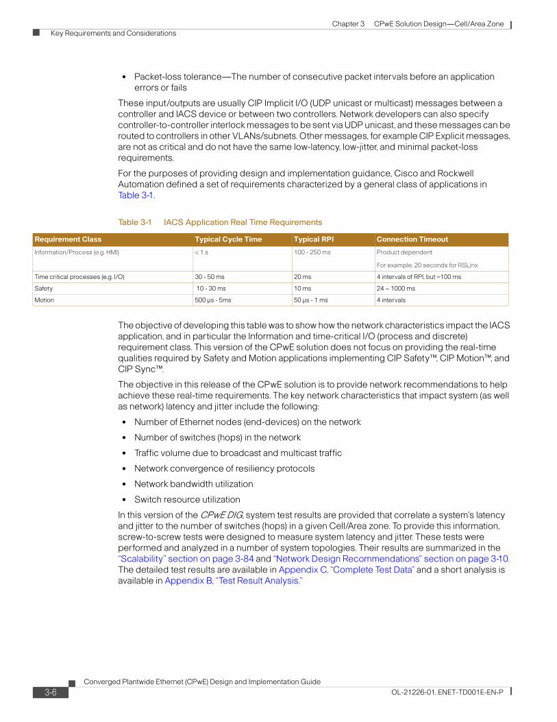
For the purposes of providing design and implementation guidance, Cisco and Rockwell Automation defined a set of requirements characterized by a general class of applications in Table 3-1.
The objective of developing this table was to show how the network characteristics impact the IACS application, and in particular the Information and time-critical I/O (process and discrete) requirement class. This version of the CPwE solution does not focus on providing the real-time qualities required by Safety and Motion applications implementing CIP Safety™, CIP Motion™, and CIP Sync™.
The objective in this release of the CPwE solution is to provide network recommendations to help achieve these real-time requirements. The key network characteristics that impact system (as well as network) latency and jitter include the following:
• Number of Ethernet nodes (end-devices) on the network
• Number of switches (hops) in the network
• Traffic volume due to broadcast and multicast traffic
• Network convergence of resiliency protocols
• Network bandwidth utilization
• Switch resource utilization
In this version of the CPwE DIG, system test results are provided that correlate a system's latency and jitter to the number of switches (hops) in a given Cell/Area zone. To provide this information, screw-to-screw tests were designed to measure system latency and jitter. These tests were performed and analyzed in a number of system topologies. Their results are summarized in the “Scalability” section on page 3-84 and “Network Design Recommendations” section on page 3-10. The detailed test results are available in Appendix C, “Complete Test Data” and a short analysis is available in Appendix B, “Test Result Analysis.”
Table 3-1 IACS Application Real Time Requirements
Requirement Class Typical Cycle Time Typical RPI Connection Timeout
Information/Process (e.g. HMI) < 1 s 100 - 250 ms Product dependent
For example, 20 seconds for RSLinx
Time critical processes (e.g. I/O) 30 - 50 ms 20 ms 4 intervals of RPI, but =100 ms
Safety 10 - 30 ms 10 ms 24 – 1000 ms
Motion 500 μs - 5ms 50 μs - 1 ms 4 intervals
3-6Converged Plantwide Ethernet (CPwE) Design and Implementation Guide
OL-21226-01, ENET-TD001E-EN-P
Chapter 3 CPwE Solution Design—Cell/Area Zone
Key Requirements and Considerations
Availability
In the Cell/Area zone, the critical IACS equipment that keeps the plant operational is interconnected through the IACS network infrastructure. In this application network, availability is a major requirement. Every major design decision is made balancing availability with cost considerations. These considerations increase overall equipment effectiveness (OEE) by reducing the impact of a failure, and they speed recovery from an outage that lowers mean-time-to-repair (MTTR). The considerations elaborated later in this chapter include the following:
• Equipment choice-the level of availability of the network is only as good as the components that make up the infrastructure. In general, the following factors should be considered:
– Industrial characteristics to reduce the MTTR
– Ease and efficiency of replacement features to reduce impact of a failure
– Support for network features and functions related to overall availability (for example, resiliency protocols supported)
• Eliminate single points of failure in the network infrastructure especially devices in critical roles, (for example, having redundant distribution and core switches).
• Multiple paths in the network uplink cabling (using variants of the redundant star or ring topologies).
• Resilient network protocols in place to meet application tolerance requirements to packet loss and application connection timeouts.
• Applying a QoS approach to protect and prioritize key IACS traffic.
• Segmentation to limit the impact of a failure or breach.
• Show the impact of network characteristics, such as network convergence, has on the application, like CIP Implicit I/O connection timeout.
• Multicast management to limit the impact of multicast messages on the network and end-devices.
• Employ network resiliency methods to reduce the risk of application shutdowns. For example, employing network convergence techniques can prevent CIP Implicit I/O connection timeouts.
• Where multicast is used, implement multicast management to limit the impact of multicast messages on the network and end-devices.
It is challenging, in a lab or in a manufacturing environment, to identify and measure the overall impact many of these considerations have on availability and operational efficiency. The cost of downtime varies widely in manufacturing environments. However, the above points are generally considered best practices and in many cases are worth the additional investment.
In the end though, the critical factor is whether the IACS applications continue to operate given any specific outage or failure. There is also a relationship between the availability and what is referred to as the deterministic requirements. An IACS system will fail or timeout when the network is unavailable for a certain period of time. That period of time is directly related to the level of determinism required by the IACS. For example, a requested packet interval (RPI) from a Rockwell Automation controller to its I/O device might be 25 ms. The default timeout for this connection would be 100ms—if the controller does not hear from the device in 100ms, the connection is timed out, an error is indicated and quite possibly the application is disrupted-depending on how the system was designed. Table 3-2 outlines the target network convergence (defined in Appendix A, “Key Terms and Definitions”) times where the application will not timeout if network services are restored in that time period.
3-7Converged Plantwide Ethernet (CPwE) Design and Implementation Guide
OL-21226-01, ENET-TD001E-EN-P
Chapter 3 CPwE Solution Design—Cell/Area Zone
Key Requirements and Considerations
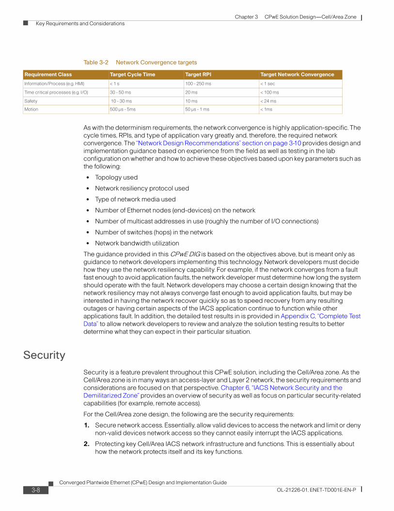
As with the determinism requirements, the network convergence is highly application-specific. The cycle times, RPIs, and type of application vary greatly and, therefore, the required network convergence. The “Network Design Recommendations” section on page 3-10 provides design and implementation guidance based on experience from the field as well as testing in the lab configuration on whether and how to achieve these objectives based upon key parameters such as the following:
• Topology used
• Network resiliency protocol used
• Type of network media used
• Number of Ethernet nodes (end-devices) on the network
• Number of multicast addresses in use (roughly the number of I/O connections)
• Number of switches (hops) in the network
• Network bandwidth utilization
The guidance provided in this CPwE DIG is based on the objectives above, but is meant only as guidance to network developers implementing this technology. Network developers must decide how they use the network resiliency capability. For example, if the network converges from a fault fast enough to avoid application faults, the network developer must determine how long the system should operate with the fault. Network developers may choose a certain design knowing that the network resiliency may not always converge fast enough to avoid application faults, but may be interested in having the network recover quickly so as to speed recovery from any resulting outages or having certain aspects of the IACS application continue to function while other applications fault. In addition, the detailed test results in is provided in Appendix C, “Complete Test Data” to allow network developers to review and analyze the solution testing results to better determine what they can expect in their particular situation.
Security
Security is a feature prevalent throughout this CPwE solution, including the Cell/Area zone. As the Cell/Area zone is in many ways an access-layer and Layer 2 network, the security requirements and considerations are focused on that perspective. Chapter 6, “IACS Network Security and the Demilitarized Zone” provides an overview of security as well as focus on particular security-related capabilities (for example, remote access).
For the Cell/Area zone design, the following are the security requirements:
1. Secure network access. Essentially, allow valid devices to access the network and limit or deny non-valid devices network access so they cannot easily interrupt the IACS applications.
2. Protecting key Cell/Area IACS network infrastructure and functions. This is essentially about how the network protects itself and its key functions.
Table 3-2 Network Convergence targets
Requirement Class Target Cycle Time Target RPI Target Network Convergence
Information/Process (e.g. HMI) < 1 s 100 - 250 ms < 1 sec
Time critical processes (e.g. I/O) 30 - 50 ms 20 ms < 100 ms
Safety 10 - 30 ms 10 ms < 24 ms
Motion 500 μs - 5ms 50 μs - 1 ms < 1ms
3-8Converged Plantwide Ethernet (CPwE) Design and Implementation Guide
OL-21226-01, ENET-TD001E-EN-P
Chapter 3 CPwE Solution Design—Cell/Area Zone
Key Requirements and Considerations
The purpose of the security design is to provide these functions to protect the Cell/Area zone from intentional or unintentional attacks. The security design for the Cell/Area zone looks at the following types of attacks:
• Inappropriate access to network infrastructure
• Spanning Tree attack
• MAC flooding
• MAC spoofing
• VLAN hopping
• VLAN tagging
• DHCP starvation
• Rogue DHCP
The Cell/Area zone security section outlines how these attacks can be mitigated and summarize the network security. The security requirements are also discussed in the following sections of the Cell/Area zone design:
• Network component selection
• Logical segmentation and VLANs
• Availability and network resiliency
• Quality-of-Service (QoS)
Manageability
Manageability is a significant issue for the IACS network, but especially for the Cell/Area zone. Control engineers or maintenance personnel, with varying degrees of industrial Ethernet networking expertise, are more likely to have some or all responsibility for the network operations and performance in the Cell/Area zone. Furthermore, issues in the Cell/Area zone have direct operational impact on the plant. Control engineers and maintenance personnel want access to and information about the health of the network when issues arise, even if the network is not the source of the issue. Manageability is a key source of requirements and considerations including the following:
• Easy to deploy, configure, monitor, and maintain the network infrastructure.
• Accessible via common tools and applications and the ability to integrate network status and configuration into the IACS system.
In this section, manageability is considered in the following network design areas:
• Network component selection
• Segmentation and VLANs
• Network security
Scalability
Cell/Area zone scalability is a debatable quality. In general, Cisco and Rockwell Automation recommend smaller VLANs and Cell/Area zones to manage network performance and improve overall security. Scaling for large plants and numbers of devices is a function of the Manufacturing zone, which interconnects the presumed larger number of Cell/Area zones. Nonetheless, it is
3-9Converged Plantwide Ethernet (CPwE) Design and Implementation Guide
OL-21226-01, ENET-TD001E-EN-P
Chapter 3 CPwE Solution Design—Cell/Area Zone
Network Design Recommendations
understood that certain plant floor scenarios may require larger Cell/Area zones. Therefore, this CPwE solution provides guidance for limitations on the size of a Cell/Area zone. The size of a Cell/Area zone is an inverse relationship with the following system characteristics:
• Network and device bandwidth. IACS end-devices tend to be the bottleneck as they often can only handle a limited amount of communication
• The number of multicast groups generated
• The latency and jitter that can be tolerated
• Network convergence
Manufacturing Partners, Machine Builders, and System Integrators
Manufacturing partners and suppliers, such as machine builders and system integrators, should also take these Cell/Area zone design recommendations into consideration for their solutions. Often their solutions are either considered Cell/Area zones or may connect directly into Cell/Area zones. If supplying complete solutions that include network infrastructure, these concepts and recommendations in this chapter are relevant, if not wholly accepted by the vendor or supplier, then at least representative of the type of network the solution may be connecting into. Some specific questions to consider include:
How ready are these solutions to be integrated into the manufacturer's industrial network infrastructure? Consider the following to align the partner solution industrial Ethernet configurations with manufacturer's network and security policies:
• Does the solution rely on standard Ethernet and TCP/IP protocol suite as the foundation for the industrial network infrastructure?
• Does the solution incorporate managed switches to consistently implement network and security services?
• What IP addressing approach is assumed or required including:
– What type of addresses are used? How many? Can it be adjusted? Can the default gateway settings be adjusted? Is network address translation (NAT) required?
• What network services are applied such as: Virtual LANs (VLANs), multicast management, quality-of-service (QoS), resilient topologies and protocols, Layer 2 and Layer 3. How would the machine or solution integrate into a network that does apply these?
• How can the machine or solution be accesses for maintenance and support?
• What security is required and how secure is the machine or solution; for example, has port security, access control lists, network access control been applied?
• Has the machine or solution been developed with considerations towards emerging industrial control system security standards such as ISA-99 and NIST 800-82?
Network Design RecommendationsThis section outlines the key design considerations for the Cell/Area zone. These are meant to be used as a reference. This is not a cookbook or how-to guide that presents a step-by-step approach to designing a network, but does layout the key features and design input based on the Cisco and Rockwell Automation best practices and experience for a Cell/Area IACS network. The key topics covered in this section include the following:
3-10Converged Plantwide Ethernet (CPwE) Design and Implementation Guide
OL-21226-01, ENET-TD001E-EN-P
Chapter 3 CPwE Solution Design—Cell/Area Zone
Network Design Recommendations
• Traffic flow—Flow of information between the various endpoints
• Component selection
• Network topology—Layout and orientation of the network equipment
• Logical segmentation and VLANs
• Availability and network resiliency
• Multicast management
• Traffic prioritization via QoS
• Security
• Scalability
Components
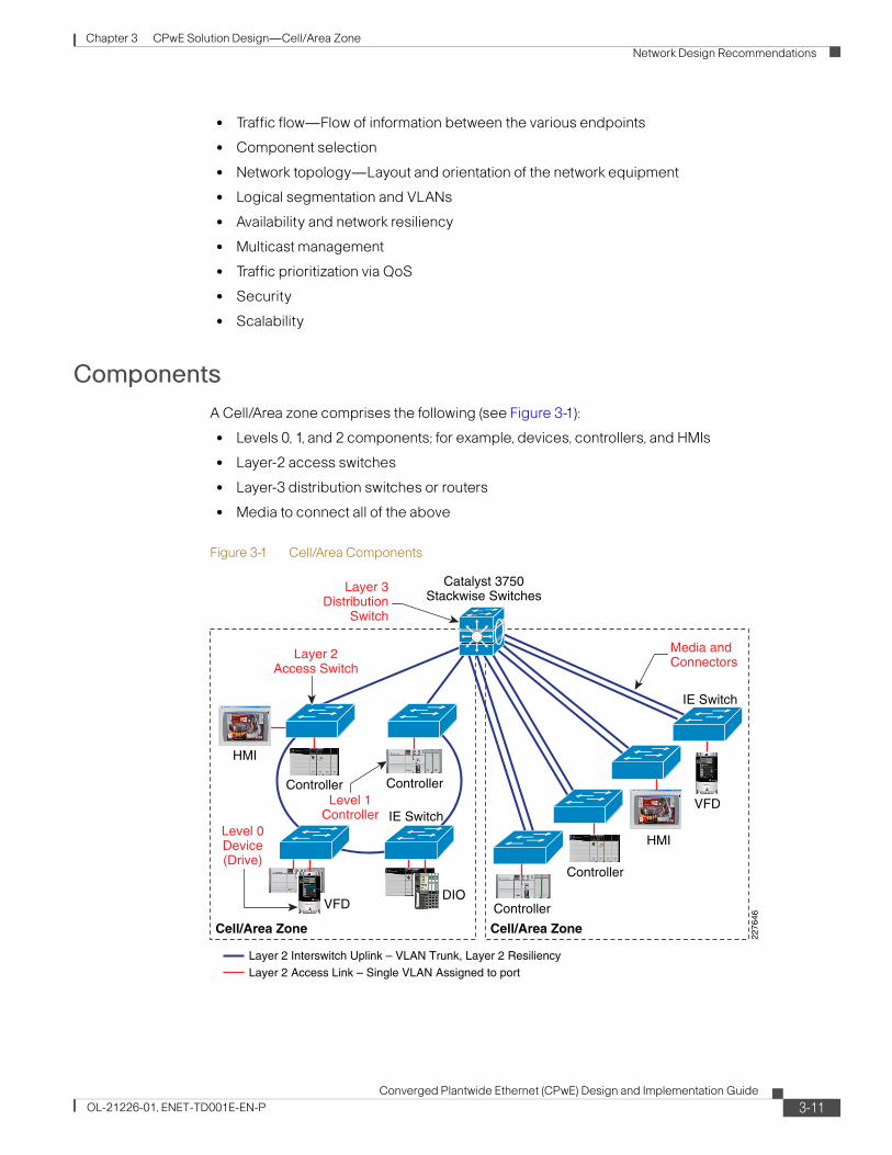
A Cell/Area zone comprises the following (see Figure 3-1):
• Levels 0, 1, and 2 components; for example, devices, controllers, and HMIs
• Layer-2 access switches
• Layer-3 distribution switches or routers
• Media to connect all of the above
Figure 3-1 Cell/Area Components
2276
46
Catalyst 3750Stackwise Switches
VFD
VFD
ControllerController
HMI
Cell/Area Zone Cell/Area Zone
IE Switch
IE Switch
Controller
Controller
HMI
DIO
Layer 3Distribution
Switch
Media andConnectors
Level 1Controller
Level 0Device(Drive)
Layer 2Access Switch
Layer 2 Access Link – Single VLAN Assigned to port
Layer 2 Interswitch Uplink – VLAN Trunk, Layer 2 Resiliency
3-11Converged Plantwide Ethernet (CPwE) Design and Implementation Guide
OL-21226-01, ENET-TD001E-EN-P
Chapter 3 CPwE Solution Design—Cell/Area Zone
Network Design Recommendations
This CPwE DIG does not provide guidance about the selection or implementation of the actual IACS equipment or the media used to connect the devices and switches. The equipment included in the test lab used to validate the overall solution is listed in the Chapter 7, “Testing the CPwE Solution.”
The key considerations network developers make when selecting the network infrastructure include the following:
• Cost—Managed switches are typically more expensive than unmanaged switches. Hubs are not commonly used in IACS networks due to the lack of diagnostics, lack of collision avoidance and other key switching features.
• Environment—Does the switch meet the environmental conditions in which the equipment must operate?
• Availability—How critical is the process being supported by the Cell/Area IACS network? What level of operation is the Cell/Area IACS network expected to operate? What is the cost of downtime?
• Flexibility—What variations of power, number of ports, type of media connections, mounting, and so on, does the switch support to meet the variety of situations in the plant environment?
• Manageability—Can the device be easily maintained? What support and warranty options are available? Often, IACS applications can be operational for more than five years, even into decades.
• Security—What security capabilities does the switch provide?
• Support—What type of support is available? What are the warranty options available?
Managed versus Unmanaged Switches
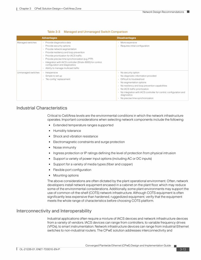
There is a significant distinction in the network infrastructure between intelligent, managed switches, and unmanaged switches. Unmanaged switches require minimal or no configuration, but they do not support advanced features such as multicast management, resiliency, segmentation, port mirroring, security, diagnostics, or QoS.
This CPwE solution design recommends the use of industrialized, managed, intelligent switches in all parts of the Cell/Area zone network infrastructure. Although unmanaged switches may initially meet the objectives of small, standalone networks their functionality will be limited when the need to scale and integrate the IACS application arises. Table 3-3 shows some advantages and disadvantages of managed and unmanaged switches.
3-12Converged Plantwide Ethernet (CPwE) Design and Implementation Guide
OL-21226-01, ENET-TD001E-EN-P
Chapter 3 CPwE Solution Design—Cell/Area Zone
Network Design Recommendations
Industrial Characteristics
Critical to Cell/Area levels are the environmental conditions in which the network infrastructure operates. Important considerations when selecting network components include the following:
• Extended temperature ranges supported
• Humidity tolerance
• Shock and vibration resistance
• Electromagnetic constraints and surge protection
• Noise immunity
• Ingress protection or IP ratings defining the level of protection from physical intrusion
• Support a variety of power input options (including AC or DC inputs)
• Support for a variety of media types (fiber and copper)
• Flexible port configuration
• Mounting options
The above considerations are often dictated by the plant operational environment. Often, network developers install network equipment encased in a cabinet on the plant floor, which may reduce some of the environmental considerations. Additionally, some plant environments may support the use of common-of-the-shelf (COTS) network infrastructure. Although COTS equipment is often significantly less expensive than hardened, ruggedized equipment, verify that the equipment meets the whole range of characteristics before choosing COTS platform.
Interconnectivity and Interoperability
Industrial applications often require a mixture of IACS devices and network infrastructure devices from a variety of vendors. IACS devices can range from controllers, to variable frequency drives (VFDs), to smart instrumentation. Network infrastructure devices can range from industrial Ethernet switches to non-industrial routers. The CPwE solution addresses interconnectivity and
Table 3-3 Managed and Unmanaged Switch Comparison
Advantages Disadvantages
Managed switches • Provide diagnostics data
• Provide security options
• Provide network segmentation
• Provide resiliency and loop prevention
• Provide prioritization for IACS traffic
• Provide precise time synchronization (e.g. PTP)
• Integration with IACS controller (Stratix 8000) for control, configuration and diagnostics
• Ability to manage multicast traffic
• More expensive
• Requires initial configuration
Unmanaged switches • Inexpensive
• Simple to set up
• “No config” replacement
• No security option
• No diagnostic information provided
• Difficult to troubleshoot
• No segmentation options
• No resiliency and loop prevention capabilities
• No IACS traffic prioritization
• No integration with IACS controller for control, configuration and diagnostics
• No precise time synchronization
3-13Converged Plantwide Ethernet (CPwE) Design and Implementation Guide
OL-21226-01, ENET-TD001E-EN-P
Chapter 3 CPwE Solution Design—Cell/Area Zone
Network Design Recommendations
interoperability of these devices through the use of standard networking technologies. Interconnectivity is addressed by CPwE through the use a standard Ethernet and IP at the data link and network layers as outlined in Chapter 1, “Converged Plantwide Ethernet Overview.” Interoperability between IACS devices, and between IACS and network infrastructure devices, is addressed by CPwE through the use of CIP as the common application layer protocol. The ability for the network infrastructure, especially within the Cell/Area zone, to communicate directly with the IACS applications has distinct advantages when commissioning and troubleshooting Cell/Area IACS network.
Consideration of the following is important when selecting network infrastructure:
1. Support for key standard network protocols including VLANs, IGMP, standard network resiliency protocols like Rapid Spanning Tree and Link Aggregation Control (LACP) protocols, support for QoS at Layer-3 Differentiated Services Code Point (DSCP) support, SNMP, etc.
2. Integration with IACS applications requires support for the industrial application layer protocols such as CIP.
Real-Time Communications
A switch plays a key role in real-time communications. Key considerations for a switch performance include the following:
• Bandwidth supported on both access ports (typically 100 Mbps) and uplink ports (typically 1 Gbps).
• Virtual LAN (VLAN) support. VLANs allow several devices to be logically grouped, regardless of their physical location into a single broadcast domain. Using VLANs to segment traffic flows is key to achieving overall system performance.
• QoS is becoming more and more critical to converged IACS networks. QoS capable switches should have include:
– QoS support at both the Layer-2 Ethernet/CoS and Layer 3 IP/DSCP.
– Ability to identify, classify and mark traffic based upon a wide range of Layer 1 to 7 characteristics (Ethernet through application header information).
– Queues supported and queuing algorithms supported. Often two egress queues are no longer sufficient to prioritize and manage the number of application types in an IACS application. Four egress queues are common criteria for industrial Ethernet switches.
• Multicast management features (for example, IGMP snooping). For more information about IGMP, see the “Multicast Management” section on page 3-54.
• Support for CIP Sync and IEEE 1588 – Precision Time Protocol. Some IACS applications require the precision these standards provide. When using CIP Sync and IEEE 1588, the switching infrastructure plays a key role beyond simply passing the timing packets. The switches must provide hardware or software support for these protocols to keep clocks tightly synchronized. This CPwE DIG does not cover CIP Synch or IEEE 1588 systems other than to note that these may be a consideration for switch selection.
Availability
The switch impacts overall availability of the IACS because the switch is often a single point-of-failure if devices are connected only to a single switch. Thus, availability considerations are important and include the following:
• Passive cooling or no moving parts (for example, fans).
3-14Converged Plantwide Ethernet (CPwE) Design and Implementation Guide
OL-21226-01, ENET-TD001E-EN-P
Chapter 3 CPwE Solution Design—Cell/Area Zone
Network Design Recommendations
• Mean time to break/fix or mean time between failure (MTBF) ratings.
• Ability to be powered from two power sources to increase availability.
• Network storm control and rate limiting to protect the network and other devices from out-of-control network communications.
• Support for standard IT convergence protocols, such as STP, RSTP, MSTP, and LACP as well as standard industrial convergence protocols such as Device Level Ring (DLR) by the ODVA. For more information about Spanning Tree, see the “Spanning Tree Protocol (STP)” section on page 3-43. Note that DLR is not covered in this version of the CPwE solution.
• In some cases, support for nonstandard convergence protocols to achieve faster network resiliency for certain applications (for example, I/O communication) such as Resilient Ethernet Protocol (REP), and Flex Links are required. Note that REP is not covered in this version of the CPwE solution.
• Network device resiliency technologies such as StackWise that offer use of multiple switching acting as one entity.
Manageability
The manageability of the network infrastructure is also important. The switch is typically maintained by plant floor operations personnel who may have minimal industrial Ethernet network expertise. Basic management functions such as initial configuration, break/fix, and monitoring need to be relatively easy. Key considerations include the following:
• SNMP capable—Most network device vendors support management via the Simple Network Management protocol (SNMP) v31.
• Quick installation features to allow minimal time and expertise to replace failed network infrastructure, such as swappable compact flash where all required operating systems and configuration files are stored. This means that plant maintenance personnel can get the plant up and running again in the middle of the night when a switch fails without the need to call IT support or a network expert.
• Ease of installation, setup, and maintenance. The network infrastructure should be easy to install, set up and maintain with key basic functions available to plant floor personnel and applications. Optimally, the network devices should interface with and be configured by common IACS tools and applications which are already in use by plant floor personnel.
– Smartport configurations—Smartports allow pre-defined port configurations to be used that ease configuration of a switch.
– Support multiple monitoring and configuration interfaces, such as command-line for network experts, browser-based interfaces, SNMP and support for IACS protocols (for example, CIP) for direct communication with the IACS systems.
• Warranty and support.
• CIP support—The ability for the switch to interface to and be configured by common IACS tools and applications already in use by maintenance.
• IACS software integration—Beyond support for CIP easy integration into the IACS applications such as FactoryTalk Production and Performance Suite to simplify access to network status and basic network configuration for plant floor personnel.
1. SNMP v3 requires the cryptographic (K9) version of IOS on the switch. Some cryptographic features are subject to additional export and contract restrictions. Rockwell Automation does not yet distribute this version of the IOS. For more information about export trade restrictions, see http://www.cisco.com/web/about/doing_business/legal/global_export_trade/index.html
3-15Converged Plantwide Ethernet (CPwE) Design and Implementation Guide
OL-21226-01, ENET-TD001E-EN-P
Chapter 3 CPwE Solution Design—Cell/Area Zone
Network Design Recommendations
Security
The Layer-2 access switch can play an important role in security as a port of entry to the Manufacturing and Cell/Area zones. Some key considerations when selecting network infrastructure equipment include the following:
• Access control lists (ACLs) to configure security policies into a switch.
• Virtual LAN support as a basic building block of a security approach. For more information about VLANs, see “Logical Segmentation and VLANs” section on page 3-32.
• Secure Shell (SSH)1 switch OS access.
• SNMPv32 support for encryption of this important protocol for managing and monitoring the network infrastructure.
• MAC filtering and address notification.
• DHCP snooping to maintain the integrity of this key network function.
• QoS trust boundaries to maintain proper use of this key network function.
• Port security via MAC address identification or physical barrier to the port.
Scalability
When selecting IACS network infrastructure, a key requirement is port-density flexibility. Implementers cannot always predetermine how many IACS devices need to be connected to a switch. Flexibility in the port density is a key aspect of controlling costs and supporting the variety of IACS network requirements. Key requirements in an industrial Ethernet switch include:
• Ability to configure a large variety of ports
• The Cisco and Rockwell Automation industrial Ethernet switches come in various port densities:
– 2 Gb dual-purpose uplink ports with native copper or fiber SFPs (single mode or multimode)
– 4 - 24 10/100 Mb copper
– 8 100 Mb fiber ports with 4-16 10/100 Mb copper ports
1. SH and SNMP v3 require the cryptographic (K9) version of IOS on the Cisco IE 3000 and Allen-Bradley Stratix 8000 industrial Ethernet switches. Some cryptographic features are subject to additional export and contract restrictions. For more information about export trade restrictions, see http://www.cisco.com/web/about/doing_business/legal/global_export_trade/index.html for the IE 3000 or contact your Rockwell Automation sales representative or distributor for details for the Stratix 8000.2. SSH and SNMP v3 require the cryptographic (K9) version of IOS on the Cisco IE 3000 and Allen-Bradley Stratix 8000 industrial Ethernet switches. Some cryptographic features are subject to additional export and contract restrictions. For more information about export trade restrictions, see http://www.cisco.com/web/about/doing_business/legal/global_export_trade/index.html for the IE 3000 or contact your Rockwell Automation sales representative or distributor for details for the Stratix 8000.
3-16Converged Plantwide Ethernet (CPwE) Design and Implementation Guide
OL-21226-01, ENET-TD001E-EN-P
Chapter 3 CPwE Solution Design—Cell/Area Zone
Network Design Recommendations
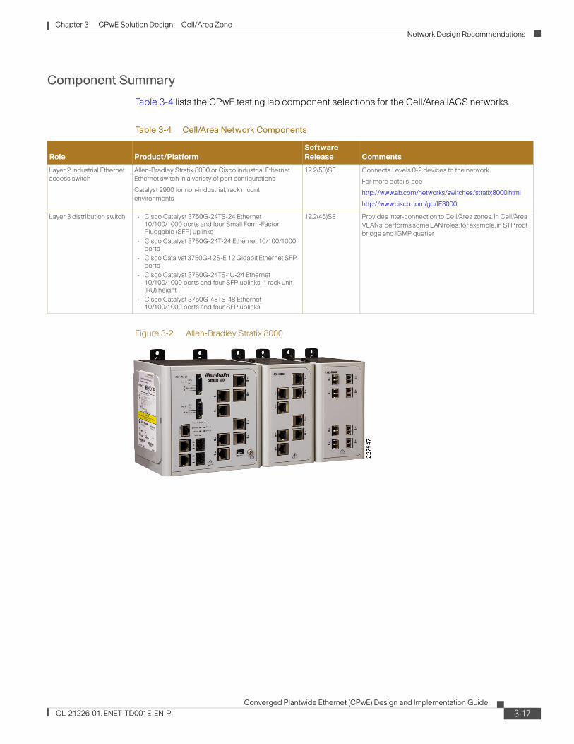
Component Summary
Table 3-4 lists the CPwE testing lab component selections for the Cell/Area IACS networks.
Figure 3-2 Allen-Bradley Stratix 8000
Table 3-4 Cell/Area Network Components
Role Product/PlatformSoftware Release Comments
Layer 2 Industrial Ethernet
access switch
Allen-Bradley Stratix 8000 or Cisco industrial Ethernet
Ethernet switch in a variety of port configurations
Catalyst 2960 for non-industrial, rack mount
environments
12.2(50)SE Connects Levels 0-2 devices to the network
For more details, see
http://www.ab.com/networks/switches/stratix8000.html
http://www.cisco.com/go/IE3000
Layer 3 distribution switch • Cisco Catalyst 3750G-24TS-24 Ethernet 10/100/1000 ports and four Small Form-Factor Pluggable (SFP) uplinks
• Cisco Catalyst 3750G-24T-24 Ethernet 10/100/1000 ports
• Cisco Catalyst 3750G-12S-E 12 Gigabit Ethernet SFP ports
• Cisco Catalyst 3750G-24TS-1U-24 Ethernet 10/100/1000 ports and four SFP uplinks, 1-rack unit (RU) height
• Cisco Catalyst 3750G-48TS-48 Ethernet 10/100/1000 ports and four SFP uplinks
12.2(46)SE Provides inter-connection to Cell/Area zones. In Cell/Area
VLANs, performs some LAN roles; for example, in STP root
bridge and IGMP querier.
3-17Converged Plantwide Ethernet (CPwE) Design and Implementation Guide
OL-21226-01, ENET-TD001E-EN-P
Chapter 3 CPwE Solution Design—Cell/Area Zone
Network Design Recommendations
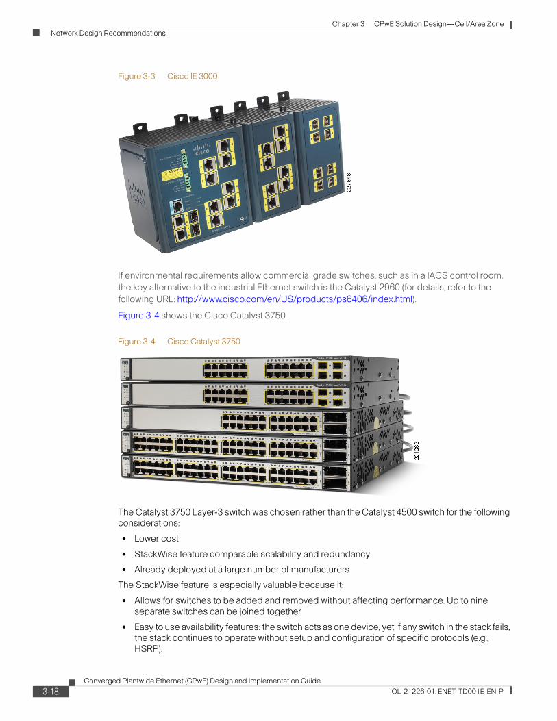
Figure 3-3 Cisco IE 3000
If environmental requirements allow commercial grade switches, such as in a IACS control room,
the key alternative to the industrial Ethernet switch is the Catalyst 2960 (for details, refer to the
following URL: http://www.cisco.com/en/US/products/ps6406/index.html).
Figure 3-4 shows the Cisco Catalyst 3750.
Figure 3-4 Cisco Catalyst 3750
The Catalyst 3750 Layer-3 switch was chosen rather than the Catalyst 4500 switch for the following considerations:
• Lower cost
• StackWise feature comparable scalability and redundancy
• Already deployed at a large number of manufacturers
The StackWise feature is especially valuable because it:
• Allows for switches to be added and removed without affecting performance. Up to nine separate switches can be joined together.
• Easy to use availability features: the switch acts as one device, yet if any switch in the stack fails, the stack continues to operate without setup and configuration of specific protocols (e.g., HSRP).
3-18Converged Plantwide Ethernet (CPwE) Design and Implementation Guide
OL-21226-01, ENET-TD001E-EN-P
Chapter 3 CPwE Solution Design—Cell/Area Zone
Network Design Recommendations
A chassis-based switch such as the Catalyst 4500 or Catalyst 6500 may be ideal in the following situations:
• Capacity or scalability is a concern; for example, when integrating a large number of Cell/Area IACS networks.
• Upgradeable processor and interfaces for longer-term viability.
• Better failover features for availability; for example, in-service upgradeability.
• When service modules (such as firewall and application delivery) are required.
The IACS network components used in this phase of the CPwE solution architecture are connected via single connections to the network infrastructure. This is common for IACS network devices applying the CIP protocol. Some controllers may support more than one Ethernet connection; multiple connections are supported for the purpose of scalability, segmentation, developing a linear topology or controller availability. These multiple connection applications for Cell/Area IACS network devices are not considered in this release of the CPwE solution architecture at this time.
Traffic Flows
Traffic flow in a Cell/Area IACS network is largely determined by the design and implementation of the IACS. These systems produce very different traffic patterns than the client-server and Internet-based applications in the IT domain or enterprise network. For example, 80 to 90 percent of the Cell/Area traffic is local as compared to a typical IT LAN in which perhaps less than 10 percent of the traffic is local. This is primarily driven by the cyclical I/O data being communicated on very short intervals (milliseconds) from devices to controllers and workstations/HMIs all on the same LAN or VLAN.
A network infrastructure should be designed to support the proper traffic flows. Features such as network segmentation can impact the network traffic flows and network performance.
Key considerations when designing traffic flows include the following:
• EtherNet/IP implementations have traditionally been unable to route multicast traffic since the time-to-live field in the IP packet is set to 1. Although updated CIP EtherNet/IP specifications (CIP Specifications version 1.3, Volume 2 EtherNet/IP Adaptation of CIP, December 2006) call for this limit to be removed, this DIG (DIG) is based on the implementation of TTL=1, because the routing of multicast traffic requires a more complex set of protocols and considerations to be applied.
The use of multicast for Implicit CIP I/O traffic is an application choice. The most recent version of the Rockwell Automation PAC configuration application (RSLogix 5000) version 18 and later, supports the choice of unicast or multicast delivery for certain types of Implicit I/O data. Explicit messaging data has always been unicast delivery via TCP. This CPwE DIG is based on multicast delivery. Devices and controllers configured for multicast delivery need to be located within the same Cell/Area IACS network as these packets cannot be routed, meaning that any router will drop the packet before forwarding it outside of the subnet/VLAN. Devices and controllers configured for unicast delivery, Implicit I/O or Explicit messaging, do not need to be within the same Cell/Area zone as that communication is routable.
Note Cisco and Rockwell Automation recommend that network developers design smaller Cell/Area IACS networks using multicast delivery and to route unicast delivery between Cell/Area zones for controller-to-controller information exchange and interlocking.
3-19Converged Plantwide Ethernet (CPwE) Design and Implementation Guide
OL-21226-01, ENET-TD001E-EN-P
Chapter 3 CPwE Solution Design—Cell/Area Zone
Network Design Recommendations
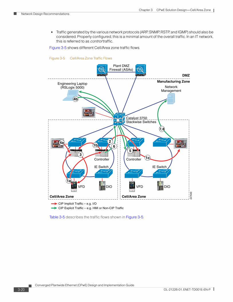
• Traffic generated by the various network protocols (ARP, SNMP, RSTP, and IGMP) should also be considered. Properly configured, this is a minimal amount of the overall traffic. In an IT network, this is referred to as control traffic.
Figure 3-5 shows different Cell/Area zone traffic flows.
Figure 3-5 Cell/Area Zone Traffic Flows
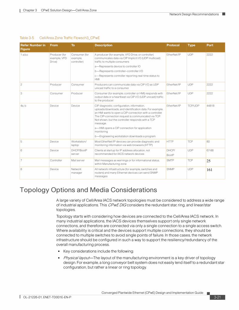
Table 3-5 describes the traffic flows shown in Figure 3-5.
2276
49
Plant DMZFirewall (ASAs)
Engineering Laptop(RSLogix 5000) Network
Management
Manufacturing Zone
DMZ
Catalyst 3750Stackwise Switches
VFD DIO
Controller
Cell/Area Zone
IE Switch
VFD DIO
Controller
Cell/Area Zone
IE Switch
1c
7, 8
4b
5
1a
3
4a1b
26
CIP Explicit Traffic – e.g. HMI or Non-CIP Traffic
CIP Implicit Traffic – e.g. I/O
3-20Converged Plantwide Ethernet (CPwE) Design and Implementation Guide
OL-21226-01, ENET-TD001E-EN-P
Chapter 3 CPwE Solution Design—Cell/Area Zone
Network Design Recommendations
Topology Options and Media Considerations
A large variety of Cell/Area IACS network topologies must be considered to address a wide range of industrial applications. This CPwE DIG considers the redundant star, ring, and linear/star topologies.
Topology starts with considering how devices are connected to the Cell/Area IACS network. In many industrial applications, the IACS devices themselves support only single network connections, and therefore are connected via only a single connection to a single access switch. Where availability is critical and the devices support multiple connections, they should be connected to multiple switches to avoid single points of failure. In those cases, the network infrastructure should be configured in such a way to support the resiliency/redundancy of the overall manufacturing process.
• Key considerations include the following:
• Physical layout—The layout of the manufacturing environment is a key driver of topology design. For example, a long conveyor belt system does not easily lend itself to a redundant star configuration, but rather a linear or ring topology.
Table 3-5 Cell/Area Zone Traffic Flowsch3_CPwE
Refer Number in
Figure
From To Description Protocol Type Port
1 a,b,c Producer (for
example, VFD
Drive)
Consumer (for
example,
controller)
A producer (for example, VFD Drive, or controller)
communicates data via CIP Implicit I/O (UDP multicast)
traffic to multiple consumers
a—Represents device to controller IO
b—Represents controller–controller I/O
c—Represents controller reporting real-time status to
HMI
EtherNet/IP UDP 2222
2 Producer Consumer Producers can communicate data via CIP I/O as UDP
unicast traffic to a consumer.
EtherNet/IP UDP 2222
3 Consumer Producer Consumer (for example, controller or HMI) responds with
output data or a heartbeat via CIP I/O (UDP unicast) traffic
to the producer.
EtherNet/IP UDP 2222
4a, b Device Device CIP diagnostic, configuration, information,
uploads/downloads, and identification data. For example,
an HMI wants to open a CIP-connection with a controller.
The CIP-connection request is communicated via TCP.
Not shown, but the controller responds with a TCP
message.
a—HMI opens a CIP connection for application
monitoring
b—Engineering workstation downloads a program
EtherNet/IP TCP/UDP 44818
5 Device Workstation/
laptop
Most EtherNet/IP devices can provide diagnostic and
monitoring information via web browsers (HTTP)
HTTP TCP 80
6 Device DHCP/BootP
server
Clients at startup for IP address allocation, not
recommended for IACS network devices
DHCP/
BootP
UDP 67-88
7 Controller Mail server Mail messages as warnings or for informational status,
within Manufacturing zone
SMTP TCP 25
8 Device Network
manager
All network infrastructure (for example, switches and
routers) and many Ethernet devices can send SNMP
messages
SNMP UDP 161
3-21Converged Plantwide Ethernet (CPwE) Design and Implementation Guide
OL-21226-01, ENET-TD001E-EN-P

Chapter 3 CPwE Solution Design—Cell/Area Zone
Network Design Recommendations
• Availability—Cisco and Rockwell Automation recommend using resilient network topologies (for example, redundant star and ring) over non-redundant topologies. These allow the network to continue to function after an event such as connection loss or switch failure. Although some of these events may still lead to downtime of the IACS, a resilient network topology may reduce that chance and should improve the recovery time.
• Real-time communications—Latency and jitter are impacted by a large variety of factors, but primary by the amount of traffic and number of hops a packet must make to reach its destination. The amount of traffic in a Layer-2 network is driven by various factors, but the number of nodes is important. Key guidelines include the following:
– Amount of latency introduced per switch.
– Bandwidth should not consistently exceed 50 percent of the interface capacity on any switch.
– Switch CPU should not consistently exceed 50 to 70 percent utilization. Above this level, the chances increase significantly that the switch may not properly process control packets and start behaving abnormally.
The key connectivity considerations assumed for CPwE design recommendations include the following:
• Redundant network connections to the end-device were not considered for this phase of CPwE. Redundant connections may be used in certain industries and applications; mostly process-related industries applied to critical infrastructure.
• Industrial Ethernet access switches are connected to a distribution switch for connectivity with the Manufacturing zone applications. Dual-homed or physically separate networks were not considered as they limit convergence (see the “Logical Segmentation and VLANs” section on page 3-32 for more information)
Part of the validation phase is to generate guidelines for the size of a Cell/Area IACS network and the limits of determinism that can be achieved as the Cell/Area IACS network increases. The Cell/Area IACS network in the test environment contains up to 16 switches, in the configurations shown in the following subsections.
Access and Uplinks
An important concept to establish is the type of links used to interconnect IACS end-devices, servers, switches, and routers. This is important because they describe their key purpose and the basic functions and features that the network infrastructure will apply to the inbound and outbound traffic on that port. This CPwE solution will describe essentially three types of ports and two types of Layer 2 connections. For example, Layer 2 ports are ports on which the switch or router will direct the incoming traffic based upon the Layer-2 MAC address in the Ethernet (Layer 2) header. For Layer 3 ports (or connections), the switch or router will direct the incoming packets based upon the IP Address in the IP (Layer 3) header. Note that a Layer 3-capable switch is required to support Layer 3 ports. This document did not test or include Layer-3 industrial Ethernet switches. Layer 3 ports are discussed in more detail in Chapter 4, “CPwE Solution Design—Manufacturing and Demilitarized Zones.” For the Cell/Area zone, there are essentially two key type of ports applied:
1. Layer-2 access ports used to connect end-devices, including all IACS end-devices.
2. Layer-2 trunk or uplink ports used to interconnect Layer-2 switches and carry traffic from multiple VLANs.
3-22Converged Plantwide Ethernet (CPwE) Design and Implementation Guide
OL-21226-01, ENET-TD001E-EN-P
Chapter 3 CPwE Solution Design—Cell/Area Zone
Network Design Recommendations
Layer-2 access ports typically are termination points for the network as only one non-switching/routing device (MAC-address) is communicating on the connection. Based on this characteristic, a number of key considerations for Layer-2 access ports include the following:
• The switch assigns the port to a VLAN and tags all traffic from that port to that VLAN (see the “Logical Segmentation and VLANs” section on page 3-32 for more information).
• Turn-off aspects of the network resiliency protocol but maintain loop protection settings (see “Availability and Network Resiliency” section on page 3-41 for more information).
• Apply a QoS service policy to the port. Configure the port to trust or not trust the QoS markings on traffic entering the port (see “Quality-of-Service (QoS)” section on page 3-63).
• Apply port security and thresholds based on expected traffic patterns from IACS devices (see “Security” section on page 3-8).
Uplink or trunk ports are the inter-switch connections. Key considerations for Layer-2 trunk or uplink ports include the following:
• Use higher bandwidth ports, such as Gigabit Ethernet, since the connection caries traffic from multiple end-devices. This will help avoid congestion and bottlenecks.
• The switch assigns the port as a VLAN trunk port so it can handle packets for multiple VLANs (see the “Logical Segmentation and VLANs” section on page 3-32 for more information).
• Apply resiliency protocol to the port to manage multi-path connections between the switches that make up the network (see the “Availability and Network Resiliency” section on page 3-41 for more information).
• Apply a QoS policy and trust the QoS markings on traffic entering the port. Other switches on the network are executed to properly mark the traffic (see the “Quality-of-Service (QoS)” section on page 3-63).
• Port security and thresholds for trunk ports are not typically applied, although the VLAN, resiliency and QoS settings have some security consideration (see the relevant sections listed above).
These considerations are described in more detail in the following subsections. These considerations are also reflected in the Smartports macros that are features of the Cisco and Rockwell Automation industrial Ethernet switches. Smartports allow implementers to easily apply these concepts to the industrial Ethernet switches by following the implementation steps described in Chapter 5, “Implementing and Configuring the Cell/Area Zone.” It is important to note that these Smartport macros apply different QoS settings depending if the port or uplink is intended for IACS traffic. For example, an IP telephone has different settings than an IACS device. As well, different QoS settings are used for IACS networks than for standard IT networks.
Linear Topology
In a linear topology, the switches are connected to each other to form a chain of switches. Key characteristics include the following:
• The connection between the Layer-3 switch and the first Layer-2 switch is a natural bottleneck and more susceptible to oversubscription, which can degrade network performance.
• Simple, easy-to-implement configuration.
• Minimal amount of cabling required.
• No resiliency to loss of a connection.
• High level of flexibility for plant floor layout.
3-23Converged Plantwide Ethernet (CPwE) Design and Implementation Guide
OL-21226-01, ENET-TD001E-EN-P
Chapter 3 CPwE Solution Design—Cell/Area Zone
Network Design Recommendations
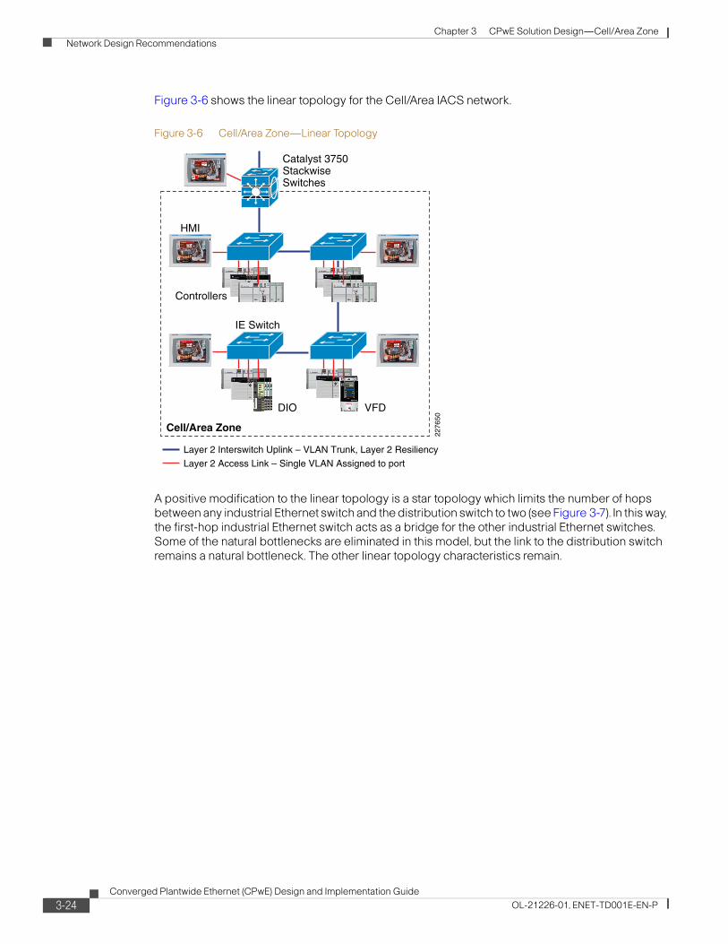
Figure 3-6 shows the linear topology for the Cell/Area IACS network.
Figure 3-6 Cell/Area Zone—Linear Topology
A positive modification to the linear topology is a star topology which limits the number of hops between any industrial Ethernet switch and the distribution switch to two (see Figure 3-7). In this way, the first-hop industrial Ethernet switch acts as a bridge for the other industrial Ethernet switches. Some of the natural bottlenecks are eliminated in this model, but the link to the distribution switch remains a natural bottleneck. The other linear topology characteristics remain.
2276
50Cell/Area Zone
Catalyst 3750StackwiseSwitches
HMI
VFDDIO
Controllers
IE Switch
Layer 2 Access Link – Single VLAN Assigned to port
Layer 2 Interswitch Uplink – VLAN Trunk, Layer 2 Resiliency
3-24Converged Plantwide Ethernet (CPwE) Design and Implementation Guide
OL-21226-01, ENET-TD001E-EN-P
Chapter 3 CPwE Solution Design—Cell/Area Zone
Network Design Recommendations
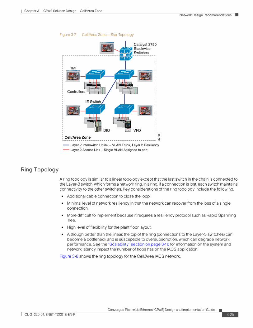
Figure 3-7 Cell/Area Zone—Star Topology
Ring Topology
A ring topology is similar to a linear topology except that the last switch in the chain is connected to the Layer-3 switch, which forms a network ring. In a ring, if a connection is lost, each switch maintains connectivity to the other switches. Key considerations of the ring topology include the following:
• Additional cable connection to close the loop.
• Minimal level of network resiliency in that the network can recover from the loss of a single connection.
• More difficult to implement because it requires a resiliency protocol such as Rapid Spanning Tree.
• High level of flexibility for the plant floor layout.
• Although better than the linear, the top of the ring (connections to the Layer-3 switches) can become a bottleneck and is susceptible to oversubscription, which can degrade network performance. See the “Scalability” section on page 3-16 for information on the system and network latency impact the number of hops has on the IACS application.
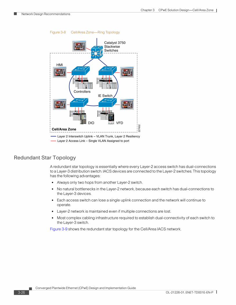
Figure 3-8 shows the ring topology for the Cell/Area IACS network.
2276
51
Cell/Area Zone
Catalyst 3750StackwiseSwitches
HMI
VFDDIO
Controllers
IE Switch
Layer 2 Access Link – Single VLAN Assigned to port
Layer 2 Interswitch Uplink – VLAN Trunk, Layer 2 Resiliency
3-25Converged Plantwide Ethernet (CPwE) Design and Implementation Guide
OL-21226-01, ENET-TD001E-EN-P
Chapter 3 CPwE Solution Design—Cell/Area Zone
Network Design Recommendations
Figure 3-8 Cell/Area Zone—Ring Topology
Redundant Star Topology
A redundant star topology is essentially where every Layer-2 access switch has dual-connections to a Layer-3 distribution switch. IACS devices are connected to the Layer-2 switches. This topology has the following advantages:
• Always only two hops from another Layer-2 switch.
• No natural bottlenecks in the Layer-2 network, because each switch has dual-connections to the Layer-3 devices.
• Each access switch can lose a single uplink connection and the network will continue to operate.
• Layer-2 network is maintained even if multiple connections are lost.
• Most complex cabling infrastructure required to establish dual-connectivity of each switch to the Layer-3 switch.
Figure 3-9 shows the redundant star topology for the Cell/Area IACS network.
2276
52
Catalyst 3750StackwiseSwitches
HMI
VFDDIO
Controllers
Cell/Area Zone
IE Switch
Layer 2 Access Link – Single VLAN Assigned to port
Layer 2 Interswitch Uplink – VLAN Trunk, Layer 2 Resiliency
3-26Converged Plantwide Ethernet (CPwE) Design and Implementation Guide
OL-21226-01, ENET-TD001E-EN-P
Chapter 3 CPwE Solution Design—Cell/Area Zone
Network Design Recommendations
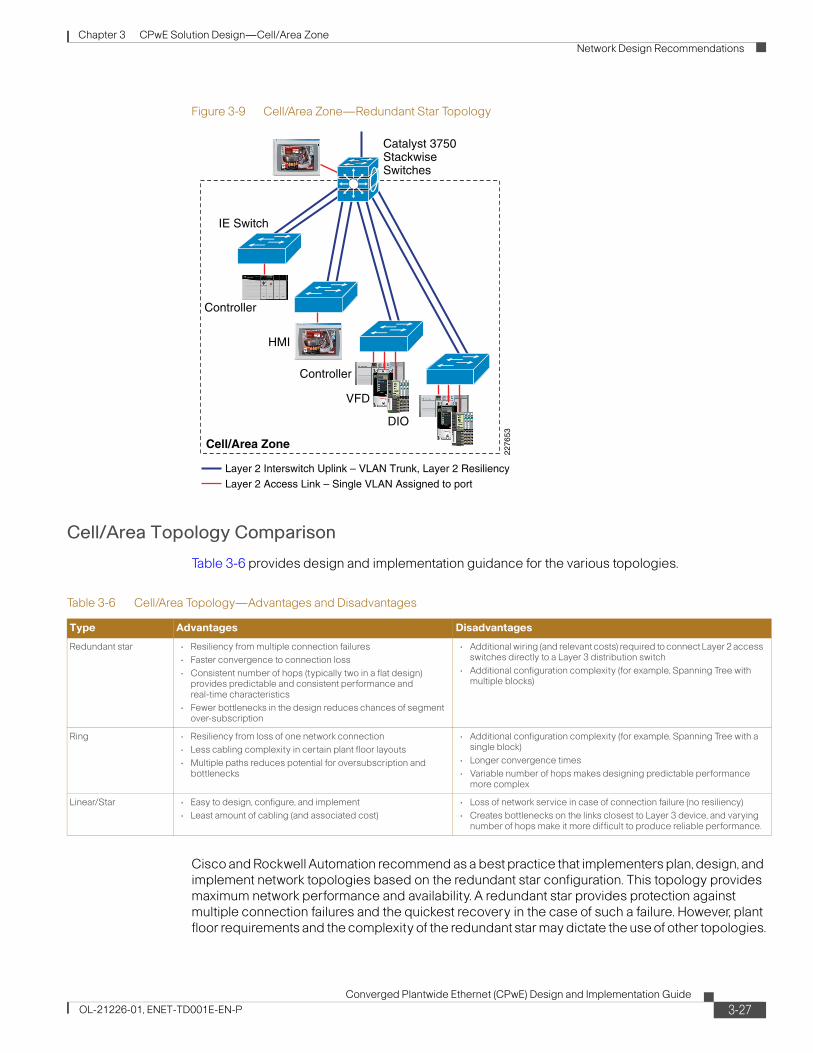
Figure 3-9 Cell/Area Zone—Redundant Star Topology
Cell/Area Topology Comparison
Table 3-6 provides design and implementation guidance for the various topologies.
Cisco and Rockwell Automation recommend as a best practice that implementers plan, design, and implement network topologies based on the redundant star configuration. This topology provides maximum network performance and availability. A redundant star provides protection against multiple connection failures and the quickest recovery in the case of such a failure. However, plant floor requirements and the complexity of the redundant star may dictate the use of other topologies.
Cell/Area Zone
Catalyst 3750StackwiseSwitches
HMI
VFD
DIO
Controller
Controller
IE Switch
2276
53
Layer 2 Access Link – Single VLAN Assigned to port
Layer 2 Interswitch Uplink – VLAN Trunk, Layer 2 Resiliency
Table 3-6 Cell/Area Topology—Advantages and Disadvantages
Type Advantages Disadvantages
Redundant star • Resiliency from multiple connection failures
• Faster convergence to connection loss
• Consistent number of hops (typically two in a flat design) provides predictable and consistent performance and real-time characteristics
• Fewer bottlenecks in the design reduces chances of segment over-subscription
• Additional wiring (and relevant costs) required to connect Layer 2 access switches directly to a Layer 3 distribution switch
• Additional configuration complexity (for example, Spanning Tree with multiple blocks)
Ring • Resiliency from loss of one network connection
• Less cabling complexity in certain plant floor layouts
• Multiple paths reduces potential for oversubscription and bottlenecks
• Additional configuration complexity (for example, Spanning Tree with a single block)
• Longer convergence times
• Variable number of hops makes designing predictable performance more complex
Linear/Star • Easy to design, configure, and implement
• Least amount of cabling (and associated cost)
• Loss of network service in case of connection failure (no resiliency)
• Creates bottlenecks on the links closest to Layer 3 device, and varying number of hops make it more difficult to produce reliable performance.
3-27Converged Plantwide Ethernet (CPwE) Design and Implementation Guide
OL-21226-01, ENET-TD001E-EN-P
Chapter 3 CPwE Solution Design—Cell/Area Zone
Network Design Recommendations
Resiliency and topology design decisions work together to meet availability requirements. (For details about resiliency, see the “Availability and Network Resiliency” section on page 3-41.)
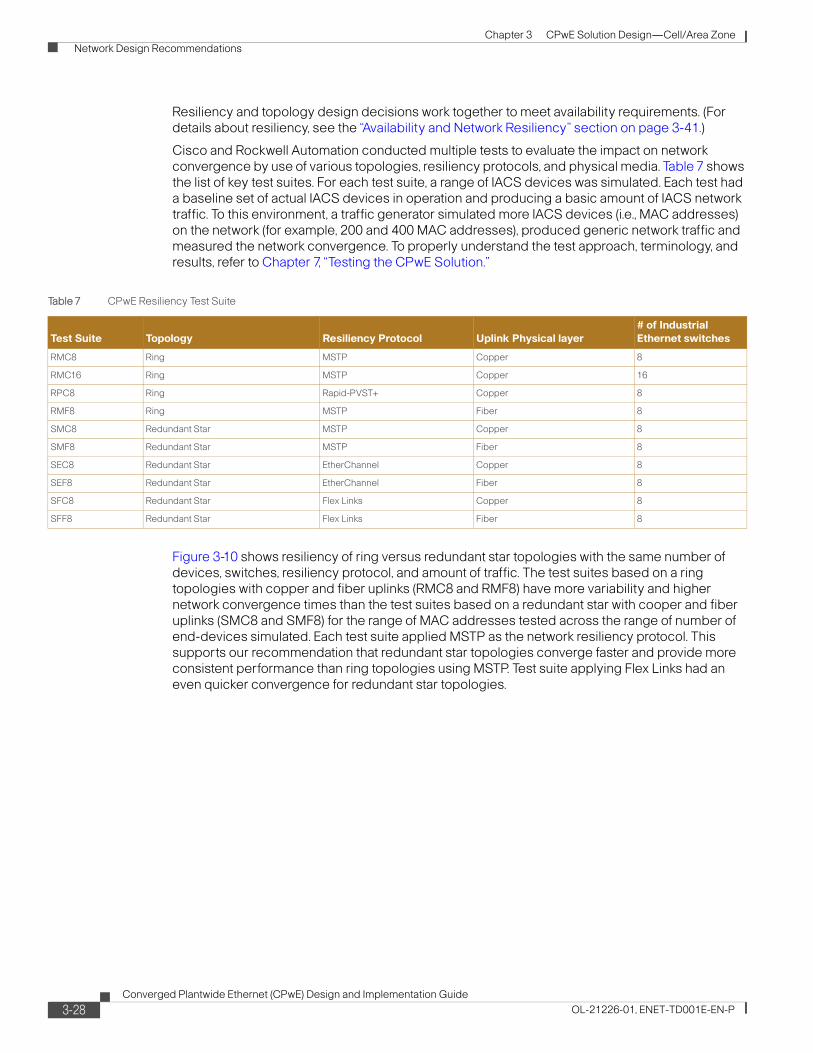
Cisco and Rockwell Automation conducted multiple tests to evaluate the impact on network convergence by use of various topologies, resiliency protocols, and physical media. Table 7 shows the list of key test suites. For each test suite, a range of IACS devices was simulated. Each test had a baseline set of actual IACS devices in operation and producing a basic amount of IACS network traffic. To this environment, a traffic generator simulated more IACS devices (i.e., MAC addresses) on the network (for example, 200 and 400 MAC addresses), produced generic network traffic and measured the network convergence. To properly understand the test approach, terminology, and results, refer to Chapter 7, “Testing the CPwE Solution.”
Figure 3-10 shows resiliency of ring versus redundant star topologies with the same number of devices, switches, resiliency protocol, and amount of traffic. The test suites based on a ring topologies with copper and fiber uplinks (RMC8 and RMF8) have more variability and higher network convergence times than the test suites based on a redundant star with cooper and fiber uplinks (SMC8 and SMF8) for the range of MAC addresses tested across the range of number of end-devices simulated. Each test suite applied MSTP as the network resiliency protocol. This supports our recommendation that redundant star topologies converge faster and provide more consistent performance than ring topologies using MSTP. Test suite applying Flex Links had an even quicker convergence for redundant star topologies.
Table 7 CPwE Resiliency Test Suite
Test Suite Topology Resiliency Protocol Uplink Physical layer
# of Industrial
Ethernet switches
RMC8 Ring MSTP Copper 8
RMC16 Ring MSTP Copper 16
RPC8 Ring Rapid-PVST+ Copper 8
RMF8 Ring MSTP Fiber 8
SMC8 Redundant Star MSTP Copper 8
SMF8 Redundant Star MSTP Fiber 8
SEC8 Redundant Star EtherChannel Copper 8
SEF8 Redundant Star EtherChannel Fiber 8
SFC8 Redundant Star Flex Links Copper 8
SFF8 Redundant Star Flex Links Fiber 8
3-28Converged Plantwide Ethernet (CPwE) Design and Implementation Guide
OL-21226-01, ENET-TD001E-EN-P
Chapter 3 CPwE Solution Design—Cell/Area Zone
Network Design Recommendations
Figure 3-10 Ring versus Redundant Star topologies
To summarize the topology recommendations, Table 8 identifies some key concerns/requirements from a implementers perspective and which topology would best address those concerns. The table provides information to help decide which topology is appropriate based on IACS requirements. The Cisco and Rockwell Automation test results show that a redundant star topology converges more quickly and more predictably than a similar sized and cabled ring infrastructure. This is a key factor in the overall recommendation of topologies.
Media Considerations
This CPwE DIG has not focused specifically on the physical media of an IACS network, as that is a highly specialized topic specific to the plant environment. However, Cisco and Rockwell Automation would like to include media considerations from a switching perspective.
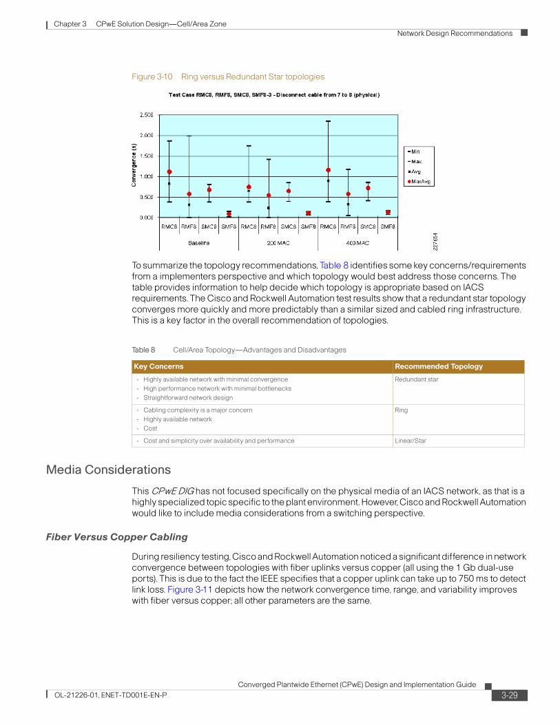
Fiber Versus Copper Cabling
During resiliency testing, Cisco and Rockwell Automation noticed a significant difference in network convergence between topologies with fiber uplinks versus copper (all using the 1 Gb dual-use ports). This is due to the fact the IEEE specifies that a copper uplink can take up to 750 ms to detect link loss. Figure 3-11 depicts how the network convergence time, range, and variability improves with fiber versus copper; all other parameters are the same.
Table 8 Cell/Area Topology—Advantages and Disadvantages
Key Concerns Recommended Topology
• Highly available network with minimal convergence
• High performance network with minimal bottlenecks
• Straightforward network design
Redundant star
• Cabling complexity is a major concern
• Highly available network
• Cost
Ring
• Cost and simplicity over availability and performance Linear/Star
3-29Converged Plantwide Ethernet (CPwE) Design and Implementation Guide
OL-21226-01, ENET-TD001E-EN-P
Chapter 3 CPwE Solution Design—Cell/Area Zone
Network Design Recommendations
Figure 3-11 Fiber Versus Copper Cabling
If network convergence is a concern, Cisco and Rockwell Automation recommend the use of fiber media to connect the network infrastructure together. This helps reduce network convergence for more time-critical IACS applications.
Uni-Directional Link Detection
In the harsh environment of a plant, physical misconnections can occur that allow a link to appear to be up when there is a mismatched set of transmit/receive pairs. This can occur at initial installation or through wear and tear of normal operations. When such a physical mismatch occurs, resiliency protocols such as STP can cause network instability. UDLD detects these physical mismatches and will disable the ports in question, allowing the resiliency protocols to maintain network availability.
UDLD is a Layer 2 protocol that enables devices connected through fiber-optic or twisted-pair Ethernet cables to monitor the physical configuration of the cables and detect when a unidirectional link exists. All connected devices must support UDLD for the protocol to successfully identify and disable unidirectional links. When UDLD detects a unidirectional link, it disables the affected port and sends alerts.
Cisco and Rockwell Automation recommend that industrial Ethernet switches are globally (versus port-specific) configured to enable UDLD in aggressive mode.
Auto-negotiate Versus Fixed Ethernet Port Interface Speed and Duplex Mode
A key consideration when deploying a standard network implementation for an IACS application is how to set some of the basic settings between the end-device and switching infrastructure, in particular the setting of the port interface speed and duplex mode. To communicate, both devices on the end of a cable have to determine what speed and duplex mode to operate in. There are two key methods to make this determination, auto-negotiate and fixed settings. Auto-negotiate, as it suggests, is the mode where the two devices negotiate the speed and duplex automatically, with the objective that the highest speed and full-duplex common to the two devices are chosen. The fixed method suggests that both ports are manually set to operate at a particular speed and duplex mode, but it is the implementer that is responsible to ensure the settings on both ends are compatible. There are no clear standards on how to proceed if there is a mismatch, but a mismatch can lead to the port being disabled (sometimes an advantage if the issue is resolved at the right
3-30Converged Plantwide Ethernet (CPwE) Design and Implementation Guide
OL-21226-01, ENET-TD001E-EN-P

Chapter 3 CPwE Solution Design—Cell/Area Zone
Network Design Recommendations
time) or operating in duplex mismatch, Devices operating in duplex mismatch may operate without error initially, but under increased load and traffic, intermittent issues may arise that are difficult to identify and resolve if not specifically monitored.
Both methods have pros and cons. Network developers need to choose the method that best supports their current environment and practices: green-field versus current installed base, end-device method support, the level of expertise and consistency of the personnel maintaining and configuring both the network and IACS devices. Cisco and Rockwell Automation do recommend the following considerations:
• Use full-duplex—This setting eliminates any issues with collisions between the end-device and the switch, and helps ensure packets are not lost between them.
• Be consistent—The best way to implement either method is consistency across the environment. Partial implementations tend to lead to more mismatches.
• Verification—In either method, Cisco and Rockwell Automation recommend that a process is put in place to validate the port settings and warn maintenance personnel when a port is operating in half-duplex, that there is a port setting mismatch or that auto-negotiation between the ports failed. Therefore, reducing the chances that the port settings become an issue while the IACS is in operations.
Here are some considerations for auto-negotiate and fixed settings:
• Auto-negotiate:
– Pro—Most new IACS devices and switch infrastructure (including the Cisco and Rockwell Automation industrial Ethernet switches) support and have auto-negotiate as the default setting for Ethernet ports.
– Pro—The auto-negotiate function requires the least amount of effort and knowledge to configure. Out of the box, most end-devices are configured to auto-negotiate, therefore requiring no configuration of these settings at time of replacement
– Pro—The auto-negotiate function includes the auto-MDIX feature which dynamically supports use of either cross-over or straight-through cabling, especially relevant for inter-switch communication.
– Con—Although rare, auto-negotiate can fail, and leave the port setting in low bandwidth or half-duplex. This is a situation that usually manifests itself in manufacturing, when traffic levels increase causing intermittent and hard to debug network problems.
– Con—Older legacy devices are in the environment have a higher tendency to either not support auto-negotiate or poorly support it, resulting in issues.
• Fixed:
– Pro—Once set, the devices will consistently operate at the configured speed and duplex.
– Con—Requires manual involvement at end-device implementation to set the fixed speed and duplex, requiring skilled time and effort
– Con—Fixed does not allow the use of auto-MDIX, which means that use of crossover cables for inter-switch communication is required for fixed deployments.
Network developers should choose upfront which method to apply in an IACS network. Fortunately, the industrial Ethernet switches, and especially the Stratix 8000, support configuration of the port settings and monitoring of port speed/duplex status. Therefore, regardless of the mechanism chosen, there are easy-to-use mechanisms to perform the required steps to implement and manage the port settings.
3-31Converged Plantwide Ethernet (CPwE) Design and Implementation Guide
OL-21226-01, ENET-TD001E-EN-P
Chapter 3 CPwE Solution Design—Cell/Area Zone
Network Design Recommendations
Summary Topology and Media Recommendations
In summary, the key CPwE network topology and media recommendations are as follows:
1. If plant availability is a concern and network recovery from outages in seconds or less is required, use a topology that offers path redundancy: redundant star or ring.
2. The redundant star topology offer performance and resiliency advantages over the ring topology, but it is more complex and costly to implement due to the wiring requirements.
3. Use higher bandwidth ports (for example, 1 Gb/sec) for uplinks and inter-switch connectivity as they carry traffic from multiple devices.
4. If network resiliency is a key requirement, use of fiber uplinks versus copper is recommended for Layer 2 uplinks.
5. Switches should have UDLD globally enabled in aggressive mode.
6. All connections should use full-duplex communication; choose a mechanism to achieve that by applying either an auto-negotiate or fixed speed/duplex approach.
Logical Segmentation and VLANs
Logical segmentation is the process of outlining which endpoints need to be in the same LAN. Segmentation is a key consideration for a Cell/Area IACS network. Segmentation is important to help manage the real-time communication properties of the network, and yet support the requirements as defined by the network traffic flows. Security is also an important consideration in making segmentation decisions. A security policy may call for limiting access of plant floor personnel (such as a vendor or contractor) to certain areas of the plant floor (such as a functional area). Segmenting these areas into distinct subnets and VLANs greatly assists in the application of these types of security considerations.
Subnets and VLANs are two concepts that go hand-in-hand. A VLAN is a broadcast domain within a switched network. Devices within a VLAN can communicate with each other without a Layer-3 switch or router. Devices in different VLANs need a Layer-3 switch or router to communicate the traffic. Subnets are simply a subset of IP addresses assigned to a set of devices. Subnets are Layer-3 (Network/IP) concepts and VLANs are Layer 2 (data-link/Ethernet). Typically, devices in a VLAN are assigned IP addresses from the same subnet and a subnet has devices in one VLAN to make routing easier and more straightforward. Best networking practice is where there is a one-to-one relationship between VLANs and subnets.
When designing IACS network logical segmentation plans, there are competing objectives. On one hand, all Level 0 to 2 devices that need to communicate multicast I/O between each other must be in the same LAN. It would seem easier to put all devices in one VLAN and subnet. However, on the other hand, the smaller the VLAN, the easier it is to manage and maintain real-time communications as the broadcast traffic and multicast traffic is constrained. Real-time communications are harder to maintain as the number of switches, devices, and the amount of network traffic increase in a LAN. Smaller VLANs also isolate devices from faulty or compromised devices that as those devices only impact the devices in their VLAN, and VLANs are the basis for setting and implementing security policy and protection. VLANs provide the broadcast isolation, policy implementation, and fault-isolation benefits that are required in highly available networks.
Note Cisco and Rockwell Automation recommend that network developers strive to design smaller LANs or VLANs, while recognizing that the traffic patterns of an IACS may make this difficult if routing is required.
3-32Converged Plantwide Ethernet (CPwE) Design and Implementation Guide
OL-21226-01, ENET-TD001E-EN-P
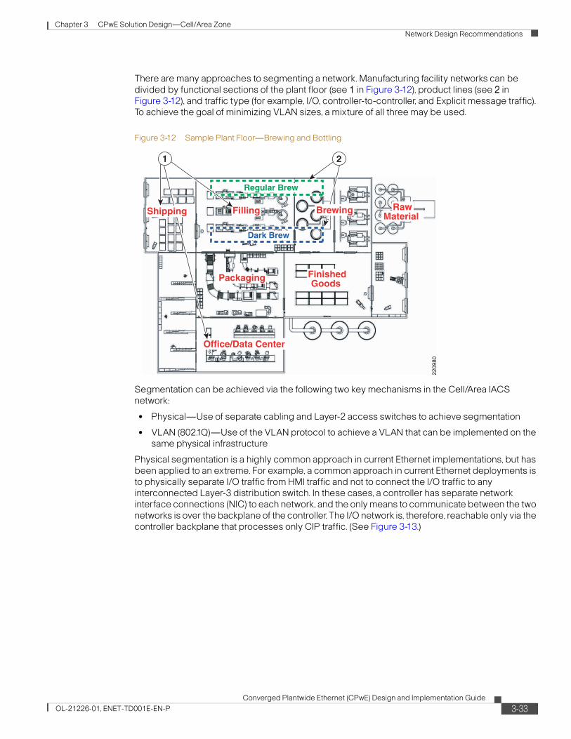
Chapter 3 CPwE Solution Design—Cell/Area Zone
Network Design Recommendations
There are many approaches to segmenting a network. Manufacturing facility networks can be divided by functional sections of the plant floor (see 1 in Figure 3-12), product lines (see 2 in Figure 3-12), and traffic type (for example, I/O, controller-to-controller, and Explicit message traffic). To achieve the goal of minimizing VLAN sizes, a mixture of all three may be used.
Figure 3-12 Sample Plant Floor—Brewing and Bottling
Segmentation can be achieved via the following two key mechanisms in the Cell/Area IACS network:
• Physical—Use of separate cabling and Layer-2 access switches to achieve segmentation
• VLAN (802.1Q)—Use of the VLAN protocol to achieve a VLAN that can be implemented on the same physical infrastructure
Physical segmentation is a highly common approach in current Ethernet implementations, but has been applied to an extreme. For example, a common approach in current Ethernet deployments is to physically separate I/O traffic from HMI traffic and not to connect the I/O traffic to any interconnected Layer-3 distribution switch. In these cases, a controller has separate network interface connections (NIC) to each network, and the only means to communicate between the two networks is over the backplane of the controller. The I/O network is, therefore, reachable only via the controller backplane that processes only CIP traffic. (See Figure 3-13.)
Regular Brew
2209
80
Filling
Packaging
Office/Data Center
RawMaterial
FinishedGoods
1 2
Shipping
Dark Brew
Brewing
3-33Converged Plantwide Ethernet (CPwE) Design and Implementation Guide
OL-21226-01, ENET-TD001E-EN-P
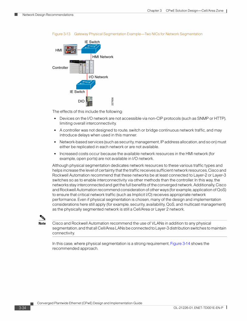
Chapter 3 CPwE Solution Design—Cell/Area Zone
Network Design Recommendations
Figure 3-13 Gateway Physical Segmentation Example—Two NICs for Network Segmentation
The effects of this include the following:
• Devices on the I/O network are not accessible via non-CIP protocols (such as SNMP or HTTP), limiting overall interconnectivity.
• A controller was not designed to route, switch or bridge continuous network traffic, and may introduce delays when used in this manner.
• Network-based services (such as security, management, IP address allocation, and so on) must either be replicated in each network or are not available.
• Increased costs occur because the available network resources in the HMI network (for example, open ports) are not available in I/O network.
Although physical segmentation dedicates network resources to these various traffic types and helps increase the level of certainty that the traffic receives sufficient network resources, Cisco and Rockwell Automation recommend that these networks be at least connected to Layer-2 or Layer-3 switches so as to enable interconnectivity via other methods than the controller. In this way, the networks stay interconnected and get the full benefits of the converged network. Additionally, Cisco and Rockwell Automation recommend consideration of other ways (for example, application of QoS) to ensure that critical network traffic (such as Implicit I/O) receives appropriate network performance. Even if physical segmentation is chosen, many of the design and implementation considerations here still apply (for example, security, availability, QoS, and multicast management) as the physically segmented network is still a Cell/Area or Layer 2 network.
Note Cisco and Rockwell Automation recommend the use of VLANs in addition to any physical segmentation, and that all Cell/Area LANs be connected to Layer-3 distribution switches to maintain connectivity.
In this case, where physical segmentation is a strong requirement, Figure 3-14 shows the recommended approach.
DIO
HMI
IE Switch
Controller
HMI Network
I/O Network
IE Switch
NIC
NIC
2276
56
3-34Converged Plantwide Ethernet (CPwE) Design and Implementation Guide
OL-21226-01, ENET-TD001E-EN-P
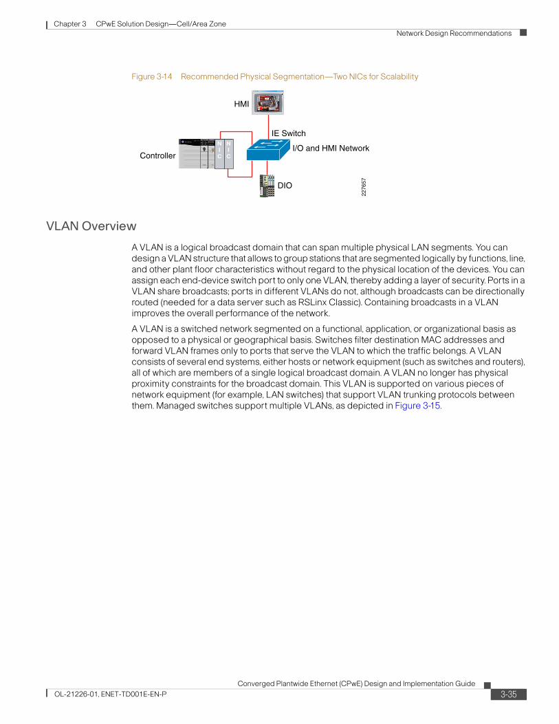
Chapter 3 CPwE Solution Design—Cell/Area Zone
Network Design Recommendations
Figure 3-14 Recommended Physical Segmentation—Two NICs for Scalability
VLAN Overview
A VLAN is a logical broadcast domain that can span multiple physical LAN segments. You can design a VLAN structure that allows to group stations that are segmented logically by functions, line, and other plant floor characteristics without regard to the physical location of the devices. You can assign each end-device switch port to only one VLAN, thereby adding a layer of security. Ports in a VLAN share broadcasts; ports in different VLANs do not, although broadcasts can be directionally routed (needed for a data server such as RSLinx Classic). Containing broadcasts in a VLAN improves the overall performance of the network.
A VLAN is a switched network segmented on a functional, application, or organizational basis as opposed to a physical or geographical basis. Switches filter destination MAC addresses and forward VLAN frames only to ports that serve the VLAN to which the traffic belongs. A VLAN consists of several end systems, either hosts or network equipment (such as switches and routers), all of which are members of a single logical broadcast domain. A VLAN no longer has physical proximity constraints for the broadcast domain. This VLAN is supported on various pieces of network equipment (for example, LAN switches) that support VLAN trunking protocols between them. Managed switches support multiple VLANs, as depicted in Figure 3-15.
DIO
IE Switch
ControllerI/O and HMI Network
NIC
NIC
2276
57
HMI
3-35Converged Plantwide Ethernet (CPwE) Design and Implementation Guide
OL-21226-01, ENET-TD001E-EN-P
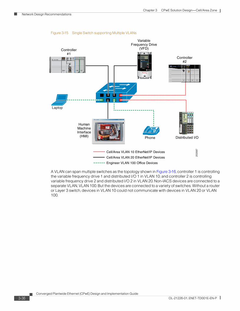
Chapter 3 CPwE Solution Design—Cell/Area Zone
Network Design Recommendations
Figure 3-15 Single Switch supporting Multiple VLANs
A VLAN can span multiple switches as the topology shown in Figure 3-16, controller 1 is controlling the variable frequency drive 1 and distributed I/O 1 in VLAN 10; and controller 2 is controlling variable frequency drive 2 and distributed I/O 2 in VLAN 20. Non-IACS devices are connected to a separate VLAN, VLAN 100. But the devices are connected to a variety of switches. Without a router or Layer 3 switch, devices in VLAN 10 could not communicate with devices in VLAN 20 or VLAN 100.
VariableFrequency Drive
(VFD)
Phone
Cell/Area VLAN 10 EtherNet/IP Devices
Cell/Area VLAN 20 EtherNet/IP Devices
Engineer VLAN 100 Office Devices
Controller#1
Laptop
IP
HumanMachineInterface
(HMI)
Controller#2
Distributed I/O
2535
87
3-36Converged Plantwide Ethernet (CPwE) Design and Implementation Guide
OL-21226-01, ENET-TD001E-EN-P
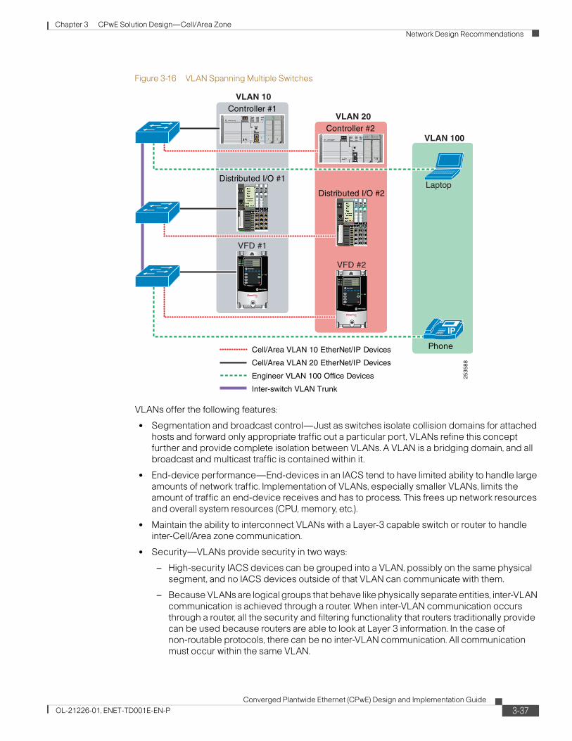
Chapter 3 CPwE Solution Design—Cell/Area Zone
Network Design Recommendations
Figure 3-16 VLAN Spanning Multiple Switches
VLANs offer the following features:
• Segmentation and broadcast control—Just as switches isolate collision domains for attached hosts and forward only appropriate traffic out a particular port, VLANs refine this concept further and provide complete isolation between VLANs. A VLAN is a bridging domain, and all broadcast and multicast traffic is contained within it.
• End-device performance—End-devices in an IACS tend to have limited ability to handle large amounts of network traffic. Implementation of VLANs, especially smaller VLANs, limits the amount of traffic an end-device receives and has to process. This frees up network resources and overall system resources (CPU, memory, etc.).
• Maintain the ability to interconnect VLANs with a Layer-3 capable switch or router to handle inter-Cell/Area zone communication.
• Security—VLANs provide security in two ways:
– High-security IACS devices can be grouped into a VLAN, possibly on the same physical segment, and no IACS devices outside of that VLAN can communicate with them.
– Because VLANs are logical groups that behave like physically separate entities, inter-VLAN communication is achieved through a router. When inter-VLAN communication occurs through a router, all the security and filtering functionality that routers traditionally provide can be used because routers are able to look at Layer 3 information. In the case of non-routable protocols, there can be no inter-VLAN communication. All communication must occur within the same VLAN.
Phone
Laptop
IP
Controller #1
Distributed I/O #1
Controller #2
Distributed I/O #2
VFD #1
VFD #2
VLAN 10
VLAN 20
VLAN 100
2535
88
Cell/Area VLAN 10 EtherNet/IP Devices
Cell/Area VLAN 20 EtherNet/IP Devices
Engineer VLAN 100 Office Devices
Inter-switch VLAN Trunk
3-37Converged Plantwide Ethernet (CPwE) Design and Implementation Guide
OL-21226-01, ENET-TD001E-EN-P
Chapter 3 CPwE Solution Design—Cell/Area Zone
Network Design Recommendations
• Network Performance—The logical grouping of devices allows, for example, an engineer making intensive use of a networked CAD/CAM station or testing a multicast application to be assigned to a VLAN that contains just that engineer and the servers or devices he or she needs. The work of this engineer does not affect the rest of the engineering group, which results in improved performance for the engineer (by being on a dedicated LAN) and improved performance for the rest of the engineering group (whose communications are not slowed down by the single engineer using the network).
• Network management—The logical grouping of IACS devices, divorced from their physical or geographic locations, allows easier network management. It is no longer necessary to pull cables to move an IACS device from one network to another. Adds, moves, and changes are achieved by configuring a port into the appropriate VLAN. Expensive, time-consuming re-cabling to extend connectivity in a switched LAN environment is no longer necessary because network management can be used to logically assign an IACS device from one VLAN to another.
For more background information or VLANs, see the following:
• VLANs and VLAN trunking— http://www.cisco.com/en/US/partner/tech/tk389/tk689/tsd_technology_support_protocol_home.html
• LAN switching and VLANs— http://www.cisco.com/en/US/tech/tk1330/tsd_technology_support_technical_reference_chapter09186a008075983b.html
• Internetwork design guide–LAN switching— http://www.cisco.com/en/US/partner/tech/tk1330/technologies_design_guide_chapter09186a008066670e.html
• Designing Switched LAN internetworks— http://www.cisco.com/en/US/partner/docs/internetworking/design/guide/nd2012.html
Any end-device to be connected directly to multiple VLANs typically requires multiple network interface cards (NICs) available to the device. For example, controllers can have multiple NIC cards installed because of their modularity, and therefore have direct Layer-2 access to multiple VLANs. This may also be a consideration in the segmentation of the network. Note though, a Layer-3 switch or router can route packets between VLANs if the appropriate security allows for that. A device need not be on multiple VLANs to talk to devices on multiple VLANs.
VLAN Design
The key steps to design a VLAN approach include the following:
Step 1 Assign the various Cell/Area zones a VLAN that corresponds to an IP subnet in which the devices in that zone all have their IP address. For more on IP addressing, see Chapter 4, “CPwE Solution Design—Manufacturing and Demilitarized Zones.”
Step 2 Determine how to deploy the VLANs into the network infrastructure.
Step 3 Determine how to configure the VLAN Interface, end-device ports and switch uplinks.
Once the VLANs and IP addressing schema has been set, the next key design decision is how to deploy VLANs into the network infrastructure. Cisco and Rockwell Automation recommend that VLANs are manually configured on the switches. IACS networks tend to be designed and configured and not updated very often, if at all during their lifetime. There are “automated” ways to
3-38Converged Plantwide Ethernet (CPwE) Design and Implementation Guide
OL-21226-01, ENET-TD001E-EN-P

Chapter 3 CPwE Solution Design—Cell/Area Zone
Network Design Recommendations
manage the VLANs in a switch, for example to exemplify the VLAN trunk protocol (VTP). But these mechanisms carry inherent risk as inadvertent changes could have significant impact to the IACS network. Therefore, Cisco and Rockwell Automation recommend that VTP is in transparent mode on the IACS network. Manual VLAN configuration requires a bit more work up front to implement the VLANs onto the network infrastructure, but once complete, it lowers this risk of operational issues due to inadvertent VTP updates.
Trunking
Trunks are also an important concept of deploying VLANs. The inter-switch connections in a Layer-2 network deploying VLANs are referred to and configured as trunks as they carry traffic for multiple VLANs. The relevant standard is IEEE 802.1Q, which specifies VLAN tagging to carry multiple VLANs on Ethernet links between switches. IEEE 802.1Q is the prevalent and most often used standard.
Cisco and Rockwell Automation recommend using IEEE 802.1Q for inter-switch connections within the Cell/Area zone. Some Cisco switches support another protocol, ISL, but that is a proprietary pre-cursor to 802.1Q and is not recommended.
As stated above, Cisco and Rockwell Automation recommend that manual configuration is used; therefore, the inter-switch connections are set to use 802.1Q and set negotiation to off to enforce use of 802.1Q.
VLAN1 and Native VLANs
Two important considerations in designing a VLAN network are the use of VLAN 1 and the native VLAN. The native VLAN is the VLAN to which a port returns when it is not trunking. Also, an IEEE 802.1Q trunk does not apply a VLAN tag to the native VLAN; in other words, the VLAN tag is implicit. The Native VLAN is the assigned VLAN for the port (and used if Trunking is removed) and is the VLAN used by network-specific protocols (for example, LACP, MSTP, or Resilient Ethernet Protocol). VLAN 1 is the default native VLAN on trunk ports on Cisco-based switches and therefore may used by a number of network infrastructure protocols. For a number of performance and security reasons (for example, VLAN hopping, for more on VLAN hopping see Chapter 7, “Testing the CPwE Solution.” Cisco and Rockwell Automation recommend the following in regards to VLAN 1 and native VLANs for trunk ports:
• Both sides of an inter-switch trunk must be configured with the same native VLAN.
• Configure the native VLAN to be a dedicated and specific VLAN not already in use: for example, IACS Cell/Area Zone VLAN. The Native VLAN should not be routed to/from and therefore is never enabled on the router or Layer 3 distribution switch. No IACS network traffic should flow in the Native VLAN.
• It is recommended that the size and scope of a Native VLAN be a Cell/Area zone . For example, on a Cell/Area zone, the same Native VLAN would reside on all the trunks between the switches.
• Configure the 802.1Q trunk to allow only specified VLANs. All other VLANs should be “pruned” from the trunk, including VLAN 1.
• Define IACS devices to use a specific VLAN other than the native VLAN and VLAN 1. Allow these VLANs on the trunks.
• Cisco and Rockwell Automation recommend to not use VLAN 1 for any purpose. Some security threats assume that VLAN 1 is the default VLAN for data and/or management traffic and may target VLAN 1 in their attacks.
3-39Converged Plantwide Ethernet (CPwE) Design and Implementation Guide
OL-21226-01, ENET-TD001E-EN-P
Chapter 3 CPwE Solution Design—Cell/Area Zone
Network Design Recommendations
Management VLANs
Management VLANs are also an important consideration when establishing a VLAN concept. In the IT and enterprise network, management VLANs are common and used as a means to access the network and IT infrastructure separate from the data VLANs. If IT is involved in managing the IACS network, they may want to establish management VLANs. Essentially, a management VLAN is a VLAN on which only the network infrastructure has IP addresses. The concept can also be taken so far as to establish an out-of-band physical network with the network infrastructure so as to allow network connectivity even when the in-band network is disrupted. Given the cost of cabling and infrastructure, this is not a consideration for most manufacturers.
Management VLANs are a supported concept, especially when IT may be involved in IACS networking. If Cell/Area zone network management is to be performed by plant floor personnel, putting the switch in the IACS VLANs provides a management interface to the network infrastructure so IACS applications (for example, controller with RSLogix 5000) can access the network infrastructure for management, monitoring and control, the same reasons why a management VLAN is established.
VLAN Numbering
VLANs are identified by a number between 1 and 4094. VLANs 1002 to 1005 are for backwards compatibility with legacy Layer-2 network protocols and cannot be used. VLANs 1006 to 4094 are the extended range VLANs. These cannot be used in conjunction with the ISL trunking protocol or VTP in client-server mode, neither of which is recommended by Cisco or Rockwell Automation for use in VLAN management.
The section on Cell/Area zone implementation will cover in detail the implementation of VLANs, but the following is a quick summary of the recommendations:
• The Cell/Area zone VLANs must be defined on a distribution/core switch (Layer 3 capable), so the switch can route between VLANs.
• All CIP-bearing VLANs should have IP directed broadcast-enabled and CIP-enabled to allow connectivity to RSLinx data servers in the Manufacturing zone. This is applied to the outbound interface on the Layer-3 switch.
• For CIP integration, the industrial Ethernet switches must have a VLAN interface defined with a specific IP address on the Cell/Area zone VLANs where the switch must communicate with CIP enabled controllers. A switch can have IP addresses in multiple Cell/Area VLANs; however, only one VLAN can be CIP-enabled.
• Set the switch in VTP mode transparent (all switches) to reduce the potential for operational error.
• Consider establishing a management VLAN, especially if IT or IT tools will be involved in the Cell/Area zone network management.
Uplinks or inter-switch connections:
• Hard set the trunk mode to ON and the encapsulation negotiate to OFF for optimal network convergence.
• On all trunk ports in switches in a Cell/Area zone, assign the native VLAN to an unused ID to avoid VLAN hopping. The native VLAN setting has to be the same on both sides of the trunk.
• Set the trunk encapsulation to dot1q.
• Manually prune all VLANs except those that are needed.
Configure the end-host ports:
3-40Converged Plantwide Ethernet (CPwE) Design and Implementation Guide
OL-21226-01, ENET-TD001E-EN-P
Chapter 3 CPwE Solution Design—Cell/Area Zone
Network Design Recommendations
• Use switchport mode host command to set the port for an access device.
• The end-device must be assigned an IP address, subnet mask, and default gateway in the appropriate subnet.
• Configure the interface for the appropriate VLAN.
For more information on VTP, refer to the following URL: http://www.cisco.com/en/US/partner/tech/tk389/tk689/technologies_tech_note09186a0080094c52.shtml#vtp_modes
For more information on VLAN best practices, refer to the following URL: http://www.cisco.com/en/US/partner/products/hw/switches/ps700/products_white_paper09186a00801b49a4.shtml#cg1
Key Segmentation and VLAN Recommendations
The following are logical segmentation and VLAN recommendations for CPwE:
• Segment the IACS network into Cell/Area zones, where each zone is a subset of devices that communicate consistently with each other. All devices should have an IP address in the same IP subnet and be in the same VLAN. Smaller Cell/Area zones are in general better.
• All devices communicating with each other via multicast (I/O) traffic must be in the same VLAN
• Layer-3 switches or routers are required to route traffic between VLANs, which may impact traffic flow.
• Each VLAN should consist of a single IP subnet.
• If non-manufacturing traffic (PC and so on) must exist in the physical topology, it should be on a separate VLAN.
• Configure VTP mode as transparent to avoid operational error because very few VLANs are used.
• Assign all end-device or host ports a VLAN and set to switchport mode access.
• Do not explicitly use VLAN 1 as it is easily misused and can cause unexpected risks (see the “Security” section on page 3-8).
• All uplinks are connected as 802.1Q trunks.
• Use an unused VLAN as the native VLAN on all trunk ports.
• Prune all unused VLANs from a trunk.
Availability and Network Resiliency
There are a number of factors that influence the availability of the network including network design, component selection, and redundancy. This section focuses on the use of network resiliency protocols to allow multiple diverse paths in the network. These protocols allow multiple paths in the network while preventing network loops. Previously highlighted recommendations that are important to availability are as follows:
• Use a network topology that offers redundant uplink paths to allow the network to quickly recover from an uplink failure.
• Use redundant network hardware for key network functions, such as the distribution switch. Cisco and Rockwell Automation testing and much of the CPwE recommendations here assume stacked, redundant distribution switches.
3-41Converged Plantwide Ethernet (CPwE) Design and Implementation Guide
OL-21226-01, ENET-TD001E-EN-P
Chapter 3 CPwE Solution Design—Cell/Area Zone
Network Design Recommendations
Use fiber media in the uplinks for faster link-down notification (see the “Fiber Versus Copper Cabling” section on page 3-29). Depending on the topology selected, various availability options can be designed into the network. If a topology is chosen with resiliency (for example, redundant star or ring), some form of network resiliency protocol is required to manage loops in the network. Loops are created when Layer-2 network devices are connected with multiple paths to reach the same destination. If left unmanaged, loops can cause serious network issues by creating broadcasts storms (messages continuously passed around the network) that quickly disrupt network service. Both standard and proprietary protocols have been developed to manage the loops and to react to connection losses by blocking and unblocking redundant links.
The protocols identify (either manually or automatically) one or more connections to be virtually turned off to eliminate loops. When a connection is lost, the protocols must recognize the disruption and reactivate a blocked connection to restore network viability. The network convergence time is a measure of how long it takes to detect a fault, find an alternate path, and recover from the fault. During the network convergence time, some portion of the traffic is dropped by the network because interconnectivity does not exist. If the convergence time is longer than the cycle time in the IACS, the systems on the affected portion of the network may stop operating and bring parts of the plant floor to a halt. Plant floor personnel and Control Engineers may decide that the additional cost of a resilient network does not provide sufficient value if the network convergence time exceeds the cycle time. Although network convergence may not be fast enough to ensure IACS uptime, Cisco and Rockwell Automation recommend the use of resilient network topologies because they allow the manufacturing operations to continue when IACS are restarted without waiting on lost connections to be restored.
Note Although network convergence may not be fast enough to ensure IACS uptime, Cisco and Rockwell Automation recommend the use of resilient network topologies because they allow the manufacturing operations to continue when IACS are restarted without waiting on lost connections to be restored.
There are standard and proprietary protocols to manage resilient network topologies. The standard protocols are based on STP, which implements the 802.1D IEEE algorithm by exchanging Bridge Protocol Data Unit (BPDU) messages with other switches to detect loops, and then removes the loop by shutting down selected bridge interfaces. This algorithm guarantees that there is only one active path between two network devices. RSTP, based on IEEE 802.1w, is an evolution of the STP 802.1D standard and provides for faster Spanning Tree convergence after a topology change. The standard also includes features equivalent to Cisco PortFast, UplinkFast, and BackboneFast for faster network convergence.
For standard resilient network technologies within a multi-vendor environment, Cisco and Rockwell Automation recommend using MSTP as the resiliency protocol. For more information, refer to the following URL:
http://www.cisco.com/en/US/partner/tech/tk389/tk621/tsd_technology_support_protocol_home.html
Resiliency Protocol overview
This section briefly provides an overview of the key resiliency protocols covered in the scope of this CPwE DIG. The overview provides a brief background on protocol (e.g., versions), an abbreviated description of how the protocol operates and a description of the key benefits of the protocol.
3-42Converged Plantwide Ethernet (CPwE) Design and Implementation Guide
OL-21226-01, ENET-TD001E-EN-P
Chapter 3 CPwE Solution Design—Cell/Area Zone
Network Design Recommendations
Spanning Tree Protocol (STP)
Spanning Tree Protocol (STP) is a Layer-2 protocol designed to run on bridges and switches. Its main purpose is to ensure that loops are avoided when there are redundant paths by deterministically blocking appropriate interfaces. If a link failure occurs in such a network, the STP is responsible for establishing a new path for data traffic.
Spanning Tree is arguably the only standard network protocol commonly available from a wide-range of vendors and across any type of topology. It is a reasonable expectation that products from two or more network infrastructure vendors would interoperate when running STP. Cisco and Rockwell Automation know of no tests to verify the interoperability of STP between vendors.
Spanning Tree is an IEEE standard. This IEEE standard has gone through several revisions since its conception which are summarized as follows:
1. Original Spanning Tree incorporated into IEEE 802.1D. STP will recover from a topology change in less than 60 seconds. Generally speaking, STP is too slow to use in IACS networks.
2. Rapid Spanning Tree known as IEEE 802.1w now incorporated into IEEE 802.1D- 2004, which significantly reduced the convergence time.
3. Multiple Spanning Tree known as IEEE 802.1s now incorporated into IEEE 802.1Q-2003 extends the RSTP to work with multiple VLANs.
The standards are backward compatible with each other, but may lose some of the performance advantages. For example, a ring of switches operating with both STP and RSTP, will default to using STP and thereby lose the performance advantages of RSTP. We recommend that when using Spanning Tree, the switches in a topology are all operating the same STP protocol.
Key advantages of Spanning Tree include the following:
• Plug-and-play, STP sends packets to determine whether loops exist in the topology. If a loop is inadvertently created and STP has not been disabled, it will detect the loop and will block a port to “close” the loop. For this feature in particular, Cisco and Rockwell Automation recommend that STP be on in a topology unless there are specific conflicts. These may mean STP is running, but not actively detecting a loop and thereby not the active resiliency protocol.
• Consistent, in the sense that on the same topology, STP will always choose the same link to block
• Supports a wide-variety of topologies. Spanning Tree will function on any redundant topology.
• Standard—Since STP is defined in various IEEE standards, infrastructure from various vendors can be configured in a topology and interoperate. This CPwE solution did not test network infrastructure from various vendors and recommends that if such a topology were to be used, that the configuration be sufficiently tested.
Key disadvantages of Spanning Tree include the following:
• Of the protocols tested, Spanning Tree and Rapid Spanning Tree converge more slowly than other protocols. Cisco and Rockwell Automation did not find that rapid Spanning Tree converges fast enough to avoid application outages on a consistent basis to recommend it for other than information/process applications.
• Original STP is the lowest common denominator of the STPs. It is supported by most hardware vendors and it’s the fall back if two devices are using incompatible Spanning Tree implementations. If multiple implementations of STP are being used, it may be the case that the original STP is unknowingly in effect due to incompatibility between the other STP variants causing long network recovery when failures occur.
In Cisco-based switches, the following three STP modes are available:
3-43Converged Plantwide Ethernet (CPwE) Design and Implementation Guide
OL-21226-01, ENET-TD001E-EN-P
Chapter 3 CPwE Solution Design—Cell/Area Zone
Network Design Recommendations
• PVST+—This spanning-tree mode is based on the IEEE 802.1D standard and Cisco proprietary extensions. It is the default spanning-tree mode used on all Ethernet port-based VLANs in non-industrial Cisco switches. The PVST+ runs on each VLAN on the switch up to the maximum supported, ensuring that each has a loop-free path through the network.
The PVST+ provides Layer-2 load balancing for the VLAN on which it runs, as a proprietary extension to IEEE 802.1D. You can create different logical topologies by using the VLANs on your network to ensure that all of your links are used but that no one link is oversubscribed. Each instance of PVST+ on a VLAN has a single root switch. This root switch propagates the spanning-tree information associated with that VLAN to all other switches in the network. Because each switch has the same information about the network, this process ensures that the network topology is maintained.
• Rapid PVST+—This spanning-tree mode is the same as PVST+ except that is uses a rapid convergence algorithm based on the IEEE 802.1w standard. To provide rapid convergence, the RPVST+ immediately deletes dynamically learned MAC address entries on a per-port basis upon receiving a topology change. By contrast, PVST+ uses a short aging time for dynamically learned MAC address entries.
The RPVST+ implementation uses the same configuration as PVST+ (except where noted), and the switch needs only minimal extra configuration. The benefit of RPVST+ is that you can migrate a large PVST+ network to RPVST+ without having to learn the complexities of the MSTP configuration and without having to re-provision your network. In RPVST+ mode, each VLAN runs its own spanning-tree instance up to the maximum supported.
• MSTP—This spanning-tree mode is based on the IEEE 802.1s standard. You can map multiple VLANs to the same spanning-tree instance, which reduces the number of spanning-tree instances required to support a large number of VLANs. The MSTP runs on top of the RSTP (based on IEEE 802.1w), which provides for rapid convergence of the Spanning Tree by eliminating the forward delay and by quickly transitioning root ports and designated ports to the forwarding state. You cannot run MSTP without RSTP. MSTP is the default for the Cisco and Rockwell Automation industrial Ethernet switches when the Express Setup is followed as described in Chapter 5, “Implementing and Configuring the Cell/Area Zone.”
Cisco and Rockwell Automation strongly recommended a single STP implementation to be applied across the entire IACS network to avoid any incompatibility between the variants.
For more information on STP and related technologies, see the Spanning Tree Protocol Introduction at the following URL: http://www.cisco.com/en/US/partner/tech/tk389/tk621/technologies_white_paper09186a0080094cfc.shtml
EtherChannel
Strictly speaking, EtherChannel and Link Aggregation Control Protocol (LACP) are not resiliency protocols. They are designed to provide additional bandwidth between two devices by aggregating multiple Ethernet connections into a higher bandwidth virtual connection. However, these protocols need to quickly recover from the loss of one or more channel members. This fast recovery from a failure of an individual channel member can be used to provide link redundancy between two devices.
EtherChannel bundles multiple Ethernet links between two switches into a single logical link. EtherChannel balances the traffic load across the various physical links. When a physical link is lost, the EtherChannel load balancing algorithm stops using the lost link and uses the available links. When the link is restored, EtherChannel resumes balancing the load across the available link. In this way, EtherChannel can be used as a resiliency protocol when multiple links exist between two
3-44Converged Plantwide Ethernet (CPwE) Design and Implementation Guide
OL-21226-01, ENET-TD001E-EN-P
Chapter 3 CPwE Solution Design—Cell/Area Zone
Network Design Recommendations
switches. To be used as a resiliency protocol, the switches must have redundant links between each other, such as in the redundant star topology. EtherChannel cannot be used in a ring topology as a resiliency protocol where the switches have one physical link between each switch.
In the Industrial Ethernet switches, there are two available protocols for establishing and managing EtherChannels:
1. Port Aggregation Protocol (PaGP) is a Cisco-proprietary protocol to be run on only Cisco switches.
2. LACP as defined in the IEEE 802.3ad standard. LACP facilitates the automatic creation of EtherChannels by exchanging LACP packets between Ethernet ports.
As Interoperability is a key requirement for the CPwE solution, Cisco and Rockwell Automation recommend the use of LACP to establish EtherChannel links between switches when multiple physical links exist. The CPwE design guidance below assumes the use of LACP.
Key advantages of EtherChannel:
• Performance—EtherChannel uses all available links simultaneously, adding bandwidth to uplink capacity.
• Fast convergence—As EtherChannel uses multiple links and converges quickly when a link-loss is detected, it can be considered for applications that are more sensitive to packet loss. See Chapter 7, “Testing the CPwE Solution” for more specific information.
• Standard—As LACP is defined in an IEEE standard, infrastructure from various vendors can be configured in a topology and interoperate. This CPwE solution did not test network infrastructure from various vendors and recommends that if such a topology were to be used, that the configuration be sufficiently tested.
Key disadvantages:
• Only works between two switches with multiple physical links between them. This limits the use of the protocol for resiliency to the redundant star configuration for Cell/Area zones.
• Configuration required. EtherChannel cannot be configured via CIP or Smartports as of yet for the Cisco and Rockwell Automation industrial Ethernet switches.
For more on EtherChannel, refer to the following URLs: http://www.cisco.com/en/US/docs/switches/lan/cisco_ie3000/software/release/12.2_50_se/configuration/guide/swstp.html#wp1082107
http://www.cisco.com/en/US/tech/tk389/tk213/technologies_white_paper09186a0080092944.shtml
http://www.cisco.com/en/US/tech/tk389/tk213/tsd_technology_support_protocol_home.html
Flex Links
Flex Links is a Cisco-proprietary resiliency protocol that is an alternative to STP and EtherChannel in redundant star networks. It is used to connect an access switch to a distribution switch. With Flex Links, you define an active uplink interface and a backup uplink interface. To begin, the active interface is in the up condition. The interface that is up sends and receives frames just like any other Ethernet port. The backup interface begins in the standby state. The standby interface establishes a link to the other side of the connection (i.e., it is up/up by both switches). However, the interface in the standby state does not send or receive and any packets. Only the interface that is up sends and receives all of the traffic to and from the switch. When a failure is detected on the forwarding link, the MAC address and multicast entries are transferred to the standby link. When the failed interface is restored, it becomes the standby link. Flex Links does not require any additional configuration on the distribution switch.
3-45Converged Plantwide Ethernet (CPwE) Design and Implementation Guide
OL-21226-01, ENET-TD001E-EN-P
Chapter 3 CPwE Solution Design—Cell/Area Zone
Network Design Recommendations
Flex Links can be used to replace STP or EtherChannel in specific topologies, namely when the access switch has dual links to the distribution switch. Flex Links does not function in a ring topology.
Flex Links contains a feature to improve the recovery of multicast traffic (in other words CIP I/O traffic). A switch with Flex Links receives IGMP queries from the querier and thus assign that port as the mrouter port (see the “Multicast Management” section on page 3-54 for more on multicast traffic flow). To accelerate multicast convergence, Flex Links will also ensure the standby port is listed as an mrouter port. But, as that port is blocked, multicast traffic will not be sent or received on that port. The second feature to improve multicast convergence is “leaking” IGMP reports out the blocked port. When the upstream or distribution switch receives these reports on this port, the port is added to the snooping table and multicast traffic is sent that direction. The Flex Links protocol on the access switch blocks the incoming traffic on the standby port. But, when a failure occurs and the standby link is unblocked, the port is already an mrouter port and the upstream switch is already forwarding multicast traffic on that interface. These features enhance the ability of this protocol to converge multicast traffic resulting in little to no outage to the EtherNet/IP connections. For more information on multicast traffic, see “Multicast Management” section on page 3-54.
Key advantages of Flex Links:
• Simple protocol to manage resilient uplinks between two switches.
• Performance—Fast convergence of unicast and multicast traffic, with built-in features to improve multicast convergence.
• Compatible with STP. As Flex Links blocks one port, STP does not identify a loop and inappropriately block any ports.
• Interoperable. Although Flex Links is proprietary, the fact that it does not communicate or negotiate with other switches, the protocol can be used in mixed vendor environments, just not running on other vendor switches.
Key disadvantages of Flex Links:
• Flex Links is Cisco proprietary—It is only available on network infrastructure operating Cisco IOS.
• Does not take advantage of the available bandwidth
• Requires configuration.
For more information about Flex Links, refer to the following URL:
http://www.cisco.com/en/US/docs/switches/lan/cisco_ie3000/software/release/12.2_50_se/configuration/guide/swflink.html
Resiliency Design
This section gives specific design considerations for deploying the various network resiliency protocols. This section assumes that one of the topologies listed in the previous section has been chosen. The design recommendations listed below are Cisco and Rockwell Automation recommendations on how to deploy the different types of protocols. See the “Summary” section on page 3-88 for specific guidance about which network resiliency protocol fits for which situation.
STP Design
Cisco and Rockwell Automation recommend using either MSTP or RPVST+ STP modes when STP is the resiliency protocol chosen. RPVST+ should be used in Cisco-only (including the Allen-Bradley Stratix 8000) environments. Using PVST+ in a mixed vendor environment may force Spanning Tree to fall back to the original 802.1D protocol. The standard IE switch configuration is
3-46Converged Plantwide Ethernet (CPwE) Design and Implementation Guide
OL-21226-01, ENET-TD001E-EN-P
Chapter 3 CPwE Solution Design—Cell/Area Zone
Network Design Recommendations
MSTP when configured with Express Setup. MSTP was selected to provide the best chance for RSTP compatibility in a multi-vendor environment. It should be noted that non-IE Cisco switches are by default in PVST+ mode. If the IE switch is connected to an existing network the Spanning Tree mode on the IE switch should be changed to be compatible with the other switches.
STP (MSTP and RPVST+) takes any arbitrary network and creates a loop free tree structure. The first step in the process it to elect a root bridge. The bridge with the lowest bridge priority becomes the root bridge. If one or more bridges have the lowest root priority, the switch with the lowest MAC address becomes the root bridge. Once the root bridge is elected, each switch determines the shortest path to the root. A switch can have only one path to the root bridge. Any paths that lead to the root but have a higher cost are blocked to prevent loops. In the event that the root is no longer reachable via the best path, the next best path will unblock.
Since the root bridge becomes the center of your Ethernet network, it is important to always select and configure the root bridge. The root bridge will typically be the distribution switch for the Cell/Area zone. If there are multiple distribution switches, one should be configured for the root bridge and the other a secondary root bridge. Not selecting the root bridges could lead to traffic flowing through a less than optimal path.
Whether using RPVST+ or MSTP, Cisco and Rockwell Automation recommend the following for Spanning Tree configurations:
• Choose only one version of STP protocol to be used within the Manufacturing and Cell/Area zones.
• Choose the distribution switch as the root bridge by setting the bridge priority.
• Enable the following additional STP features to protect against soft failures and rogue devices.
– Root Guard, which stops the introduction of a BPDU-generating bridge device that would cause a spanning-tree convergence event, such as a change in root port or path selection.
– BPDU Guard prevents the introduction of non-authorized bridging devices or switches. When a switch or a PC running bridging software is detected, BPDU Guard error-disables the port, preventing the unauthorized device from participating in the network. BPDU Guard requires operator intervention or the setting of error recovery mechanisms to re-enable the error-disabled port.
– BPDU Filter prevents port configured for BPDU guard from sending out BPDU packets.
– Loop Guard protects the network from a soft failure where physical connectivity and packet forwarding are intact but STP (BPDU generation, forwarding, and evaluation) fails.
• Set the STP link-type to point-to-point on industrial Ethernet switch uplinks for fast convergence.
• Do not make any changes to the other default STP settings, although descriptions of those are included here if that is required.
Note When deploying these recommendations, there is a difference between the default Spanning Tree settings between industrial Ethernet switches and all other Cisco IOS-based switches (e.g., Catalyst 2960, 3750 or any other non-industrial Ethernet IOS-based switch). Industrial Ethernet switches are configured by default to operate in multi-VLAN Spanning Tree mode whereas other Cisco switches are configured to operate in rapid PVST+ mode. By default, we are referring to the settings applied by the standard initial configuration steps recommended by this solution (for example using Express Setup). Out of the box, the switch is configured to operate PVST+, which applies the initial STP protocol for resiliency and loop protection.
The above recommendations are depicted in Figure 3-17.
3-47Converged Plantwide Ethernet (CPwE) Design and Implementation Guide
OL-21226-01, ENET-TD001E-EN-P
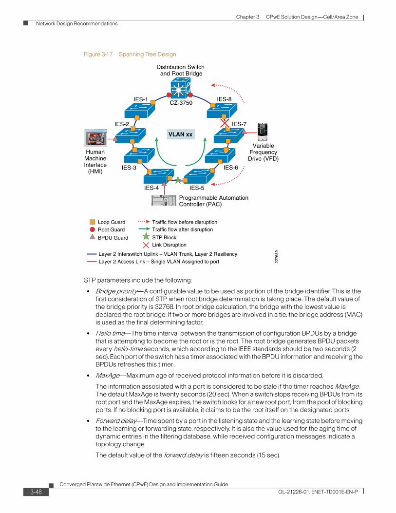
Chapter 3 CPwE Solution Design—Cell/Area Zone
Network Design Recommendations
Figure 3-17 Spanning Tree Design
STP parameters include the following:
• Bridge priority—A configurable value to be used as portion of the bridge identifier. This is the first consideration of STP when root bridge determination is taking place. The default value of the bridge priority is 32768. In root bridge calculation, the bridge with the lowest value is declared the root bridge. If two or more bridges are involved in a tie, the bridge address (MAC) is used as the final determining factor.
• Hello time—The time interval between the transmission of configuration BPDUs by a bridge that is attempting to become the root or is the root. The root bridge generates BPDU packets every hello-time seconds, which according to the IEEE standards should be two seconds (2 sec). Each port of the switch has a timer associated with the BPDU information and receiving the BPDUs refreshes this timer.
• MaxAge—Maximum age of received protocol information before it is discarded.
The information associated with a port is considered to be stale if the timer reaches MaxAge. The default MaxAge is twenty seconds (20 sec). When a switch stops receiving BPDUs from its root port and the MaxAge expires, the switch looks for a new root port, from the pool of blocking ports. If no blocking port is available, it claims to be the root itself on the designated ports.
• Forward delay—Time spent by a port in the listening state and the learning state before moving to the learning or forwarding state, respectively. It is also the value used for the aging time of dynamic entries in the filtering database, while received configuration messages indicate a topology change.
The default value of the forward delay is fifteen seconds (15 sec).
VLAN xx
HumanMachineInterface
(HMI)
IES-1
IES-7IES-2
IES-8CZ-3750
Distribution Switch and Root Bridge
IES-3
IES-4 IES-5
IES-6
VariableFrequencyDrive (VFD)
Programmable AutomationController (PAC)
Root Guard
Loop Guard
BPDU Guard
Traffic flow before disruption
STP BlockLink Disruption
Traffic flow after disruption
2276
59
Layer 2 Access Link – Single VLAN Assigned to port
Layer 2 Interswitch Uplink – VLAN Trunk, Layer 2 Resiliency
3-48Converged Plantwide Ethernet (CPwE) Design and Implementation Guide
OL-21226-01, ENET-TD001E-EN-P
Chapter 3 CPwE Solution Design—Cell/Area Zone
Network Design Recommendations
• Diameter—Maximum number of bridges between any two points of attachment of end stations. This is an optional parameter with no default. The range is 2 to 7. When the network diameter is specified, the switch automatically sets timing parameters (forward-delay, hello-time, and max-age) for a network of that diameter. If not specified (Cisco and Rockwell Automation recommendation) then the MaxAge parameter limits the topology diameter, which is by default 20 seconds or roughly 20 switches. Network diameter can have a profound effect on the operation of STP and the network as a whole because the latency of BPDUs increases as the network grows in diameter. If the configuration is used and the network is larger than the configuration suggests, the network may inadvertently split with unintended blocked connections, thus leaving sections of the network unable to communicate with other sections.
• Port cost(s)—Contribution of the path through this port, when the port is the root port, to the total cost of the path to the root for this bridge. The cost of each port between a given bridge and the root bridge contributes to the overall path cost. Some of the default values used are as follows:
– Gig E (1000 Mbps)—4
– OC-12 (622 Mbps)—6
– OC-3 (155 Mbps)—14
– FastE (100 Mbps)—19
– Ethernet (10 Mbps)—100
For more on configuring Spanning Tree in industrial Ethernet switches, refer to the following URL: http://www.cisco.com/en/US/docs/switches/lan/cisco_ie3000/software/release/12.2_50_se/configuration/guide/swstp.html#wp1082107
MSTP has additional configuration considerations from RPVST+. Where RPVST+ will by default operate in every available VLAN, MSTP maps multiple VLANs to the same Spanning Tree instance. MSTP does use the same rapid STP for quick network convergence. The key additional considerations when deploying MSTP in an IACS network include the following:
• Regions—Regions are defined by switches with common MST configurations: region name, given configuration version, and VLAN-to-instance mapping. Switches are configured as part of the same MST region by specifying the same configuration.
• Instances—Within a region, multiple Spanning Tree instances can exist. An instance may contain one or more VLANs. An instance can have specific Spanning Tree parameters for configured root, secondary root and port priority.
For the scope of testing reflected in this CPwE DIG, MST regions or instances were not tested. Our testing reflected default MSTP settings, which essentially reflect a single MST region and instance. Medium to large plants may consider applying MST Regions and instances for management and optimal convergence.
MSTP also has a parameter for maximum hop count. In rapid Spanning Tree or RPVST+, the maximum hop count was, as described, a derived concept based upon aging times. In MSTP, this is directly configurable, but be aware that the maximum aging time is also in affect. If the MSTP hop count is changed, the maximum age time may also need updates. The default settings for these suggest a maximum diameter of 20 hops or switches. These values can be increased.
3-49Converged Plantwide Ethernet (CPwE) Design and Implementation Guide
OL-21226-01, ENET-TD001E-EN-P
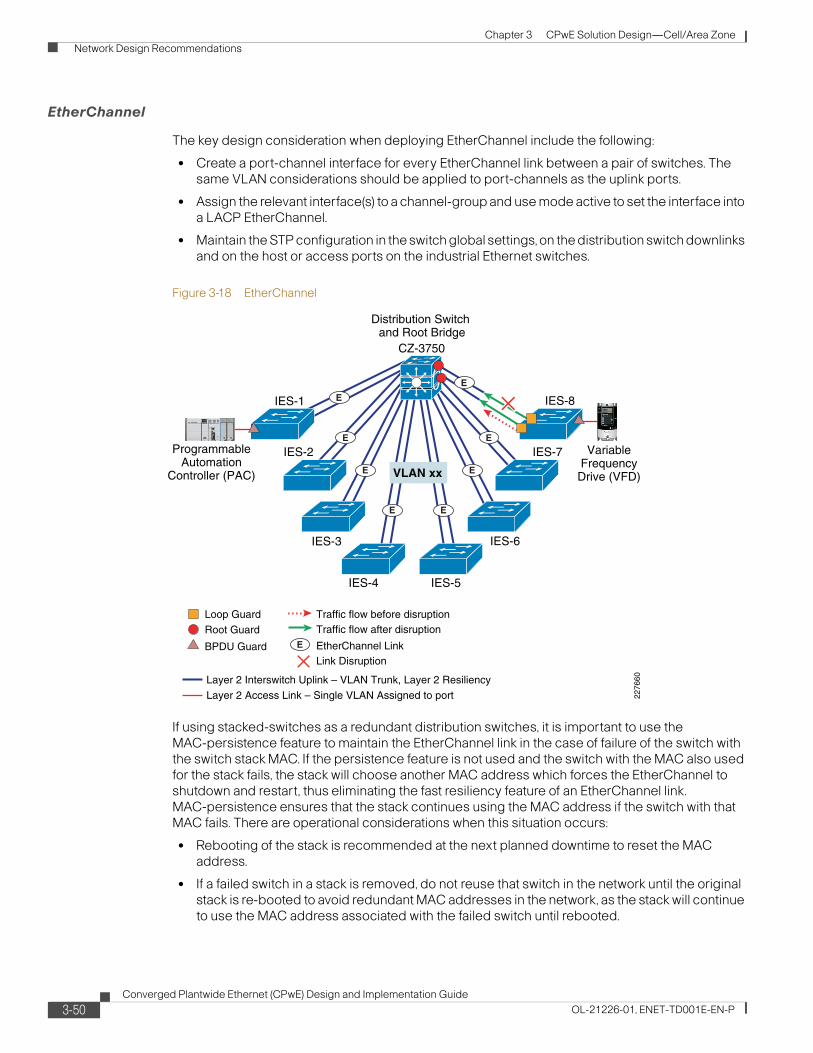
Chapter 3 CPwE Solution Design—Cell/Area Zone
Network Design Recommendations
EtherChannel
The key design consideration when deploying EtherChannel include the following:
• Create a port-channel interface for every EtherChannel link between a pair of switches. The same VLAN considerations should be applied to port-channels as the uplink ports.
• Assign the relevant interface(s) to a channel-group and use mode active to set the interface into a LACP EtherChannel.
• Maintain the STP configuration in the switch global settings, on the distribution switch downlinks and on the host or access ports on the industrial Ethernet switches.
Figure 3-18 EtherChannel
If using stacked-switches as a redundant distribution switches, it is important to use the MAC-persistence feature to maintain the EtherChannel link in the case of failure of the switch with the switch stack MAC. If the persistence feature is not used and the switch with the MAC also used for the stack fails, the stack will choose another MAC address which forces the EtherChannel to shutdown and restart, thus eliminating the fast resiliency feature of an EtherChannel link. MAC-persistence ensures that the stack continues using the MAC address if the switch with that MAC fails. There are operational considerations when this situation occurs:
• Rebooting of the stack is recommended at the next planned downtime to reset the MAC address.
• If a failed switch in a stack is removed, do not reuse that switch in the network until the original stack is re-booted to avoid redundant MAC addresses in the network, as the stack will continue to use the MAC address associated with the failed switch until rebooted.
EtherChannel LinkE
VLAN xx
IES-1
IES-7IES-2
IES-8
CZ-3750
Distribution Switch and Root Bridge
IES-3
IES-4 IES-5
IES-6
ProgrammableAutomation
Controller (PAC)
2276
60Root Guard
Loop Guard
BPDU Guard
Traffic flow before disruption
Link Disruption
Traffic flow after disruption
Layer 2 Access Link – Single VLAN Assigned to port
Layer 2 Interswitch Uplink – VLAN Trunk, Layer 2 Resiliency
E
E E
E
E E
E E
VariableFrequencyDrive (VFD)
3-50Converged Plantwide Ethernet (CPwE) Design and Implementation Guide
OL-21226-01, ENET-TD001E-EN-P
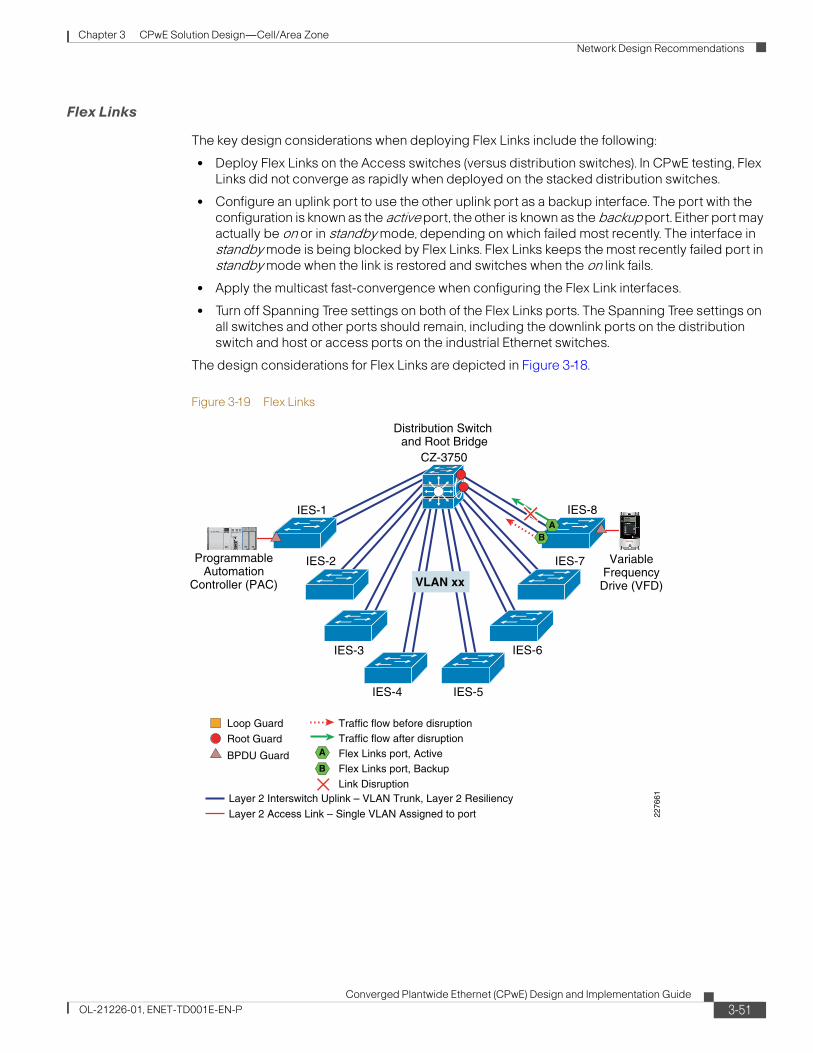
Chapter 3 CPwE Solution Design—Cell/Area Zone
Network Design Recommendations
Flex Links
The key design considerations when deploying Flex Links include the following:
• Deploy Flex Links on the Access switches (versus distribution switches). In CPwE testing, Flex Links did not converge as rapidly when deployed on the stacked distribution switches.
• Configure an uplink port to use the other uplink port as a backup interface. The port with the configuration is known as the active port, the other is known as the backup port. Either port may actually be on or in standby mode, depending on which failed most recently. The interface in standby mode is being blocked by Flex Links. Flex Links keeps the most recently failed port in standby mode when the link is restored and switches when the on link fails.
• Apply the multicast fast-convergence when configuring the Flex Link interfaces.
• Turn off Spanning Tree settings on both of the Flex Links ports. The Spanning Tree settings on all switches and other ports should remain, including the downlink ports on the distribution switch and host or access ports on the industrial Ethernet switches.
The design considerations for Flex Links are depicted in Figure 3-18.
Figure 3-19 Flex Links
VariableFrequencyDrive (VFD)VLAN xx
IES-1
IES-7IES-2
IES-8
CZ-3750
Distribution Switch and Root Bridge
IES-3
IES-4 IES-5
IES-622
7661
AB
Flex Links port, ActiveFlex Links port, Backup
Traffic flow after disruption
Link Disruption
A
B
Root Guard
Loop Guard
BPDU Guard
Traffic flow before disruption
Layer 2 Access Link – Single VLAN Assigned to port
Layer 2 Interswitch Uplink – VLAN Trunk, Layer 2 Resiliency
ProgrammableAutomation
Controller (PAC)
3-51Converged Plantwide Ethernet (CPwE) Design and Implementation Guide
OL-21226-01, ENET-TD001E-EN-P
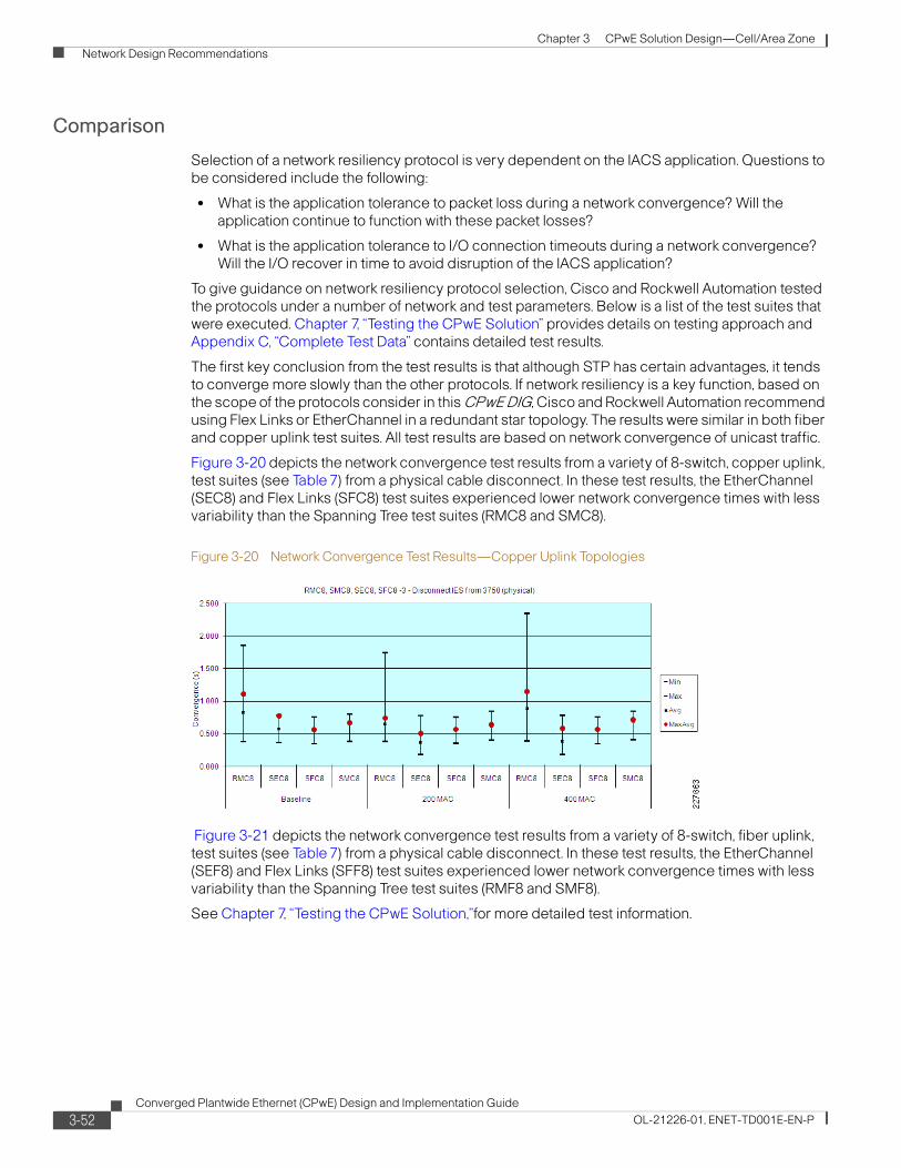
Chapter 3 CPwE Solution Design—Cell/Area Zone
Network Design Recommendations
Comparison
Selection of a network resiliency protocol is very dependent on the IACS application. Questions to be considered include the following:
• What is the application tolerance to packet loss during a network convergence? Will the application continue to function with these packet losses?
• What is the application tolerance to I/O connection timeouts during a network convergence? Will the I/O recover in time to avoid disruption of the IACS application?
To give guidance on network resiliency protocol selection, Cisco and Rockwell Automation tested the protocols under a number of network and test parameters. Below is a list of the test suites that were executed. Chapter 7, “Testing the CPwE Solution” provides details on testing approach and Appendix C, “Complete Test Data” contains detailed test results.
The first key conclusion from the test results is that although STP has certain advantages, it tends to converge more slowly than the other protocols. If network resiliency is a key function, based on the scope of the protocols consider in this CPwE DIG, Cisco and Rockwell Automation recommend using Flex Links or EtherChannel in a redundant star topology. The results were similar in both fiber and copper uplink test suites. All test results are based on network convergence of unicast traffic.
Figure 3-20 depicts the network convergence test results from a variety of 8-switch, copper uplink, test suites (see Table 7) from a physical cable disconnect. In these test results, the EtherChannel (SEC8) and Flex Links (SFC8) test suites experienced lower network convergence times with less variability than the Spanning Tree test suites (RMC8 and SMC8).
Figure 3-20 Network Convergence Test Results—Copper Uplink Topologies
Figure 3-21 depicts the network convergence test results from a variety of 8-switch, fiber uplink, test suites (see Table 7) from a physical cable disconnect. In these test results, the EtherChannel (SEF8) and Flex Links (SFF8) test suites experienced lower network convergence times with less variability than the Spanning Tree test suites (RMF8 and SMF8).
See Chapter 7, “Testing the CPwE Solution,”for more detailed test information.
3-52Converged Plantwide Ethernet (CPwE) Design and Implementation Guide
OL-21226-01, ENET-TD001E-EN-P
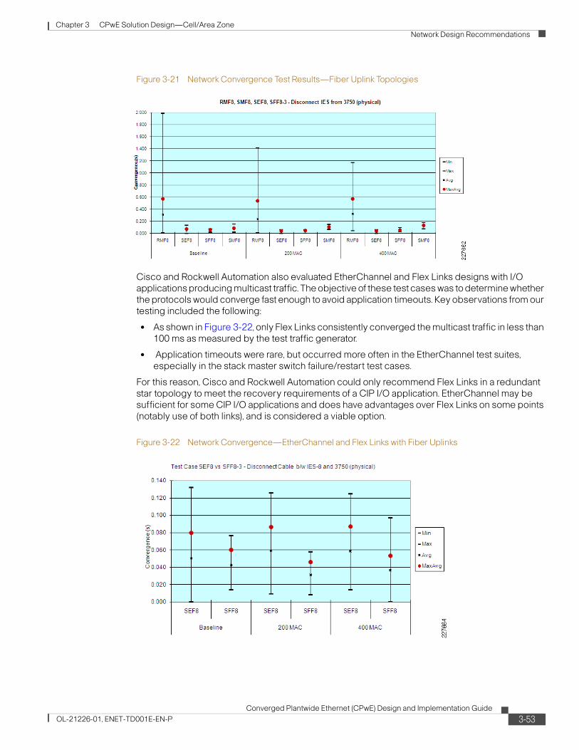
Chapter 3 CPwE Solution Design—Cell/Area Zone
Network Design Recommendations
Figure 3-21 Network Convergence Test Results—Fiber Uplink Topologies
Cisco and Rockwell Automation also evaluated EtherChannel and Flex Links designs with I/O applications producing multicast traffic. The objective of these test cases was to determine whether the protocols would converge fast enough to avoid application timeouts. Key observations from our testing included the following:
• As shown in Figure 3-22, only Flex Links consistently converged the multicast traffic in less than 100 ms as measured by the test traffic generator.
• Application timeouts were rare, but occurred more often in the EtherChannel test suites, especially in the stack master switch failure/restart test cases.
For this reason, Cisco and Rockwell Automation could only recommend Flex Links in a redundant star topology to meet the recovery requirements of a CIP I/O application. EtherChannel may be sufficient for some CIP I/O applications and does have advantages over Flex Links on some points (notably use of both links), and is considered a viable option.
Figure 3-22 Network Convergence—EtherChannel and Flex Links with Fiber Uplinks
3-53Converged Plantwide Ethernet (CPwE) Design and Implementation Guide
OL-21226-01, ENET-TD001E-EN-P
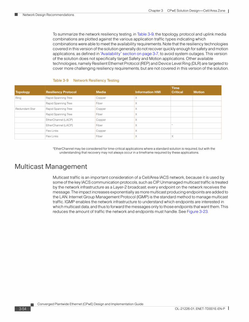
Chapter 3 CPwE Solution Design—Cell/Area Zone
Network Design Recommendations
To summarize the network resiliency testing, in Table 3-9, the topology, protocol and uplink media combinations are plotted against the various application traffic types indicating which combinations were able to meet the availability requirements. Note that the resiliency technologies covered in this version of the solution generally do not recover quickly enough for safety and motion applications, as defined in “Availability” section on page 3-7, to avoid system outages. This version of the solution does not specifically target Safety and Motion applications. Other available technologies, namely Resilient Ethernet Protocol (REP) and Device Level Ring (DLR) are targeted to cover more challenging resiliency requirements, but are not covered in this version of the solution.
*EtherChannel may be considered for time-critical applications where a standard solution is required, but with the understanding that recovery may not always occur in a timeframe required by these applications.
Multicast Management
Multicast traffic is an important consideration of a Cell/Area IACS network, because it is used by some of the key IACS communication protocols, such as CIP. Unmanaged multicast traffic is treated by the network infrastructure as a Layer-2 broadcast; every endpoint on the network receives the message. The impact increases exponentially as more multicast producing endpoints are added to the LAN. Internet Group Management Protocol (IGMP) is the standard method to manage multicast traffic. IGMP enables the network infrastructure to understand which endpoints are interested in which multicast data, and thus to forward the messages only to those endpoints that want them. This reduces the amount of traffic the network and endpoints must handle. See Figure 3-23.
Table 3-9 Network Resiliency Testing
Topology Resiliency Protocol Media Information HMI
Time
Critical Motion
Ring Rapid Spanning Tree Copper X
Rapid Spanning Tree Fiber X
Redundant Star Rapid Spanning Tree Copper X
Rapid Spanning Tree Fiber X
EtherChannel (LACP) Copper X
EtherChannel (LACP) Fiber X *
Flex Links Copper X
Flex Links Fiber X X
3-54Converged Plantwide Ethernet (CPwE) Design and Implementation Guide
OL-21226-01, ENET-TD001E-EN-P

Chapter 3 CPwE Solution Design—Cell/Area Zone
Network Design Recommendations
Figure 3-23 IGMP Impact on Multicast Network Traffic
Note Cisco and Rockwell Automation recommend that the network infrastructure be configured to manage multicast traffic.
Note Layer-2 access switches should be configured to perform IGMP snooping. When IGMP snooping is enabled, the switch listens to IGMP traffic and develops a table that lists the multicast groups and the end-devices. Thus, when a multicast packet is received, the switch forwards it only to end-devices that want it. In addition, the Layer-3 distribution switch where the LAN is connected should be configured to perform the IGMP Querier function.
Although the number of multicast addresses in a VLAN or subnet is not typically an issue, it is a consideration under certain scenarios. EtherNet/IP devices can support up to 32 multicast addresses. Typically, however, an EtherNet/IP device only uses one multicast addresses per connection. controllers can potentially use more for doing peer communications, but that may also be alleviated by choosing unicast messaging (an option in Rockwell Automation controllers). This is important because the network infrastructure has limits on the number of multicast addresses that can be supported. For example, the Cisco and Rockwell Automation industrial Ethernet switches can handle up to 256 multicast addresses. In a large, flat network, these limits may come into play. It is theoretically possible to configure a VLAN to overrun the number of multicast addresses that the industrial Ethernet switches can handle. When the switch's multicast address space is overrun, the switch simply broadcasts the multicast traffic to all IACS devices. In CPwE testing, when this situation occurred, application connections became unstable (often dropping and restarting) making the overall application unstable. This can be avoided using standard EtherNet/IP configuration guidelines and by following our logical segmentation guidelines.
In this CPwE solution architecture, IACS multicast packets are separated from the enterprise traffic by a DMZ. If they did, there is the distinct potential of redundant multicast group addresses being used that could lead to disruptions in both the IACS and the relevant IT application. For this and many other reasons, this solution architecture recommends a Demilitarized zone (DMZ) between the Manufacturing and Enterprise zone to ensure that IACS multicast traffic and IT-driven multicast traffic remain separate.
The rest of this section describes the key aspects of multicast management, including the following:
• IGMP Overview to describe the standard developed and the relevant versions
• IGMP Process describes the basic workings of the protocol
2208
86
No. of Control Devices
Mbp
s
Producer-Consumer
Multicastwith IGMPSnooping
Multicast Trafficwith no management
Unicast Traffic
3-55Converged Plantwide Ethernet (CPwE) Design and Implementation Guide
OL-21226-01, ENET-TD001E-EN-P
Chapter 3 CPwE Solution Design—Cell/Area Zone
Network Design Recommendations
IGMP Overview
The Internet Group Management Protocol (IGMP) is an integral part of IP. It must be implemented by all hosts wishing to receive IP multicasts. IGMP is part of Layer 3 and uses IP datagrams to transmit information about multicast groups. IGMP is a protocol between routers and hosts that allows group membership lists to be dynamically maintained. It should be noted though that IGMP does not determine how multicast packets are forwarded, but by listening or snooping to the IGMP messages, the network infrastructure can switch and route multicast traffic only to those hosts that request traffic from the specific multicast group. The “Multicast Traffic Flow” section on page 3-59 describes how multicast traffic is handled with network infrastructure capable of IGMP snooping.
IGMP Versions
The IGMP has been developed over time. Three major versions of the protocol exist. They mostly build upon each other and are generally backward compatible. In brief they are as follows:
• Version 1, the initial version, hosts can join a multicast group. A query function exists to monitor group interest. Typically, after a host fails to respond to three queries, the host is dropped from the group.
• Version 2, the most commonly support version, works similar to Version 1 except that hosts can actively leave a group.
• Version 3, is the latest, but not as common version. Version 3 allows for source filtering, where a consumer can choose from which producers to receive information on a particular group.
The Cisco and Rockwell Automation industrial Ethernet switches support end-hosts using all three versions. The switches do not support the source filtering feature in Version 3, although do handle the IGMP Version 3 messages. The majority of IACS EtherNet/IP devices support IGMP Version 2. If devices do support version 1 or 3, they should interoperate with the Cisco and Rockwell Automation industrial Ethernet switches. This design guidance will assume end-hosts and network infrastructure support IGMP Version 2. Cisco and Rockwell Automation recommend using end-hosts that support and are configured to operate in IGMP Version 2 to avoid any compatibility issues.
Multicast Addressing
A range of IPv4 addresses has been reserved for multicast use. The Internet Assigned Numbers Authority (IANA) assigned a class D address space to be used for IP multicast. This means that all IP multicast group addresses will fall in the range of 224.0.0.0 to 239.255.255.255. Each multicast group essentially is one multicast address.
Multiple protocols use multicast in their communication, including EtherNet/IP. EtherNet/IP specifies how end-devices generate or choose the multicast address for the groups they may produce or consume. For the most part, implementers do not have to get involved in the assignment of multicast addresses, as the end-hosts manage that on their own.
Theoretically, it is possible the multicast addresses in the IACS space may overlap with multicast addresses used in the Enterprise networks. Issues could arise if two different applications used the same multicast address within the same network zone. But a number of precautions outlined in this solution and in the underlying technology ensure that does not occur, including the following:
• EtherNet/IP multicast traffic is designed not to be routed.
• Strong segmentation between Manufacturing and Enterprise zones with firewalls ensure that the multicast traffic from either do not intermingle.
3-56Converged Plantwide Ethernet (CPwE) Design and Implementation Guide
OL-21226-01, ENET-TD001E-EN-P
Chapter 3 CPwE Solution Design—Cell/Area Zone
Network Design Recommendations
IGMP Process
The protocol describes a method for which end-hosts can subscribe to or join a multicast group and receive packets sent to that group. The concept of a process joining a multicast group on a given host interface is fundamental to multicasting. Membership in a multicast group on a given interface is dynamic (that is, it changes over time as processes join and leave the group). This means that IACS devices can dynamically join multicast groups based on the applications that they execute. The network infrastructure listens to these messages and when properly configured sends the multicast traffic between the producers and consumers.
Because IGMP is a Layer-3 protocol, this also means that the network infrastructure can send the multicast traffic to other subnets within the overall network, referred to as multicast routing. Multicast routing requires routers or Layer-3 switches enabled with Protocol Independent Multicast (PIM) to manage routing multicast traffic between producers and consumers in different VLANs or subnets. As IACS multicast traffic is constrained to the VLAN or subnet (see discussion on Time To Live or TTL below), this CPwE DIG does not focus on multicast routing, but does focus on multicast traffic and IGMP in a Layer-2 model.
In the Layer-2 model, there are two key functions played by the network infrastructure to manage multicast traffic. First, there is a querier function. IGMP queriers use IGMP messages to keep track of group membership on each of the networks that are physically attached to the router. The following rules apply:
• A host sends an IGMP report when it wants to join a multicast group. This is referred to as an unsolicited join.
• In EtherNet/IP, a host joins a group based on the TCP-based connection-open process that is conducted between producers and consumers.
• An IGMP querier sends IGMP queries at regular intervals to see whether any hosts still have processes belonging to any groups. The querier sends a query out each interface on the relevant VLAN. The group address in the query is 0 because the router expects one response from a host for every group that contains one or more members on a host. The IGMP Querier can send global or group specific queries.
• A host responds to an IGMP query by sending an IGMP report if the host still wants to receive traffic for that multicast group.
• In IGMPv2 a host will send an IGMP leave if that host no longer wants to receive traffic for a specific multicast group.
• If more than one switch or router is configured to be IGMP querier in a given VLAN, the switch or router with the lowest IP address will take this role as specified by the IGMP protocol v2.
• Global queries are sent to all ports, like a broadcast.
Note IGMP queriers do not by default track multicast groups.
The second key function is Internet Group Management Protocol (IGMP) snooping. IGMP snooping is a multicast constraining mechanism that runs on a Layer 2 LAN switch. IGMP snooping requires the LAN switch to examine some Layer 3 information (IGMP join/leave messages) in the IGMP packets sent between the hosts and the querier. The switch maintains a multicast group table similar in function to the CAM table used to track MAC addresses for switching packets. The IGMP snooping switch also tracks the ports (may be more than one per VLAN) on which multicast routers or IGMP query messages are heard, called the mrouter.
Note that IGMP query and snooping are two separate functions on industrial Ethernet switches; enabling one or the other does not enable both.
3-57Converged Plantwide Ethernet (CPwE) Design and Implementation Guide
OL-21226-01, ENET-TD001E-EN-P
Chapter 3 CPwE Solution Design—Cell/Area Zone
Network Design Recommendations
The following are two joining scenarios:
Scenario A: Host A is the first host to join a group in the segment.
Step 1 Host A sends an unsolicited IGMP Membership report.
Step 2 The switch intercepts the IGMP Membership report that was sent by the host that wanted to join the group.
Step 3 The switch creates a multicast entry for that group and links it to the port on which it has received the report and to all mrouter ports.
Step 4 The switch forwards the IGMP report to all mrouter ports. The reason is to ensure upstream switches and the IGMP Querier receive the IGMP report, and update their respective multicast routing tables.
Scenario B: Host B now is the second host on the switch to join the same group.
Step 1 Host B sends an unsolicited IGMP Membership report.
Step 2 The switch intercepts the IGMP Membership report sent by the host that wants to join the group.
Step 3 The switch does not necessarily forward the IGMP report to all router ports. Actually, the switch forwards IGMP reports to mrouter ports using proxy reporting, and only forwards one report per group within 10s.
In order to maintain group membership, the multicast router sends a IGMP query every 60 seconds. This query is intercepted by the switch, and forwarded to all ports on the switch. All hosts that are members of the group answer that query. But, given the fact that the switch intercepts the reply report as well, the other hosts do not see each of the other reports, and thus, all hosts send a report (instead of one per group). The switch then uses Proxy Reporting as well, to forward only one report per group among all received responses.
Assume Host A wants to leave the group, but Host B still wants to receive the group:
Step 1 The switch captures the IGMP Leave message from Host A.
Step 2 The switch issues a group-specific IGMP query for the group on that port (and only on that port).
Step 3 If the switch does not receive a report, it discards this port from the entry. If it receives a response from that port, it does nothing and discards the leave.
Note Cisco and Rockwell Automation industrial Ethernet switches support a port-level “Immediate-Leave” feature. This feature removes an interface from the multicast group entry immediately when a Leave is received, versus sending a group-specific query. Cisco and Rockwell Automation do not recommend using this feature for IACS networks. This feature is disabled by default.
Step 4 Host B is still interested by that group on that switch. This would not be the last non-router port in the entry. Therefore, the switch does not forward the Leave message.
3-58Converged Plantwide Ethernet (CPwE) Design and Implementation Guide
OL-21226-01, ENET-TD001E-EN-P
Chapter 3 CPwE Solution Design—Cell/Area Zone
Network Design Recommendations
Now, assume Host B wants to leave the group and Host B is the last IACS device interested by this group in this segment:
Step 1 The switch captures the IGMP leave message from Host B.
Step 2 The switch issues a group-specific IGMP query for that group on that port.
Step 3 If the switch does not receive a report, it discards this port from the entry.
Step 4 This is the last non-router port for that Group Destination Address (GDA). The switch forwards the IGMP Leave message to all router ports and removes the entry from its table.
The Time to Live (TTL) field in the IP header of reports, queries and most IACS network multicast data packets is set to 1. A multicast datagram with a TTL of 0 is restricted to the same host. By default, a multicast datagram with a TTL of 1 is restricted to the same subnet. Higher TTL field values can be forwarded by the router. Most IACS network multicast traffic has a TTL equal to 1, which restricts the traffic to the subnet or VLAN. This tends to be set by the IACS device vendor and is not configurable. If the TTL were increased, the traffic could be routed if multicast routing protocols on appropriate routers (e.g., a Layer-3-capable distribution switch), would be able to route the multicast packets. The TTL in the IP packet is decremented by 1 every time it passes through a routed hop. The TTL is not decremented when passing through Layer-2 hops, or in other words while it is in a VLAN or subnet. This version of the CPwE solution does not cover routing of multicast traffic.
For information on IP multicasting, visit Cisco Technology Support at the following URLs:
http://www.cisco.com/en/US/partner/tech/tk828/technologies_white_paper09186a0080092942.shtml
http://www.cisco.com/en/US/tech/tk1330/tsd_technology_support_technical_reference_chapter09186a00807598c3.html
http://www.cisco.com/en/US/partner/tech/tk828/tsd_technology_support_protocol_home.html
http://www.cisco.com/en/US/partner/tech/tk828/tk363/tsd_technology_support_sub-protocol_home.html
http://www.cisco.com/en/US/tech/tk828/tech_brief09186a00800a4415.html
For more information on configuring and implementing IGMP, see Chapter 5, “Implementing and Configuring the Cell/Area Zone.”
Multicast Traffic Flow
This section describes multicast traffic flow in a Layer-2 environment (i.e., VLAN or subnet). The traffic flow is described in two scenarios: normal operations and flooding, which occurs after a topology change.
Normal Operations
Without IGMP snooping, switches in a Layer 21 environment treat multicast traffic as broadcast traffic, significantly increasing bandwidth consumed and end-device processing. With IGMP Snooping in the Layer 2 switches, the switch is able to restrict switching of multicast packets out to only those ports that require it. The switch uses the multicast table and mrouter entries decide on
1. It is important to note that routing multicast traffic is possible and there is extensive description of such in the above references, but for IACS, EtherNet/IP environments, the application ensures the multicast is not routable by setting the TTL to 1, indicating the packet should not be routed.
3-59Converged Plantwide Ethernet (CPwE) Design and Implementation Guide
OL-21226-01, ENET-TD001E-EN-P
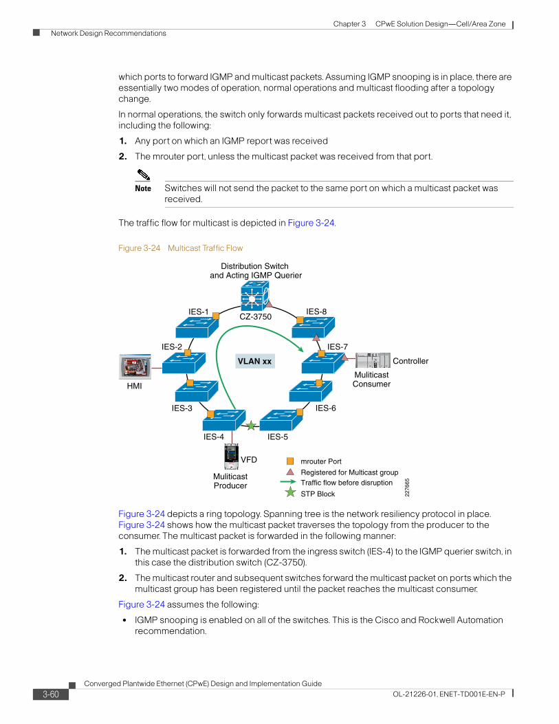
Chapter 3 CPwE Solution Design—Cell/Area Zone
Network Design Recommendations
which ports to forward IGMP and multicast packets. Assuming IGMP snooping is in place, there are essentially two modes of operation, normal operations and multicast flooding after a topology change.
In normal operations, the switch only forwards multicast packets received out to ports that need it, including the following:
1. Any port on which an IGMP report was received
2. The mrouter port, unless the multicast packet was received from that port.
Note Switches will not send the packet to the same port on which a multicast packet was received.
The traffic flow for multicast is depicted in Figure 3-24.
Figure 3-24 Multicast Traffic Flow
Figure 3-24 depicts a ring topology. Spanning tree is the network resiliency protocol in place. Figure 3-24 shows how the multicast packet traverses the topology from the producer to the consumer. The multicast packet is forwarded in the following manner:
1. The multicast packet is forwarded from the ingress switch (IES-4) to the IGMP querier switch, in this case the distribution switch (CZ-3750).
2. The multicast router and subsequent switches forward the multicast packet on ports which the multicast group has been registered until the packet reaches the multicast consumer.
Figure 3-24 assumes the following:
• IGMP snooping is enabled on all of the switches. This is the Cisco and Rockwell Automation recommendation.
VLAN xx
STP Block
Traffic flow before disruption
mrouter Port
Registered for Multicast group
HMI
IES-1
IES-7IES-2
IES-8CZ-3750
Distribution Switch and Acting IGMP Querier
IES-3
IES-4 IES-5
IES-6
VFD
MuliticastProducer
MuliticastConsumer
Controller
2276
65
3-60Converged Plantwide Ethernet (CPwE) Design and Implementation Guide
OL-21226-01, ENET-TD001E-EN-P
Chapter 3 CPwE Solution Design—Cell/Area Zone
Network Design Recommendations
• A version of Spanning Tree is enabled on all of the switches. The distribution switch is the acting root bridge, which is the Cisco and Rockwell Automation recommendation.
• The distribution switch is configured to be the acting IGMP querier (i.e., has the lowest IP address in the subnet). This is the Cisco and Rockwell Automation recommendation.
• The multicast consumer has reported interest in the multicast group which the multicast producer uses. This is described earlier in the IGMP process section.
It is important to note in this operation that all multicast traffic in a Cell/Area zone VLAN or subnet is seen by the IGMP querier switch. Therefore, to minimize the amount of multicast traffic on the switch uplinks and to limit potential bottlenecks, Cisco and Rockwell Automation recommend that the IGMP querier function is established at a central point of the normally operating network topology. Depending on the network topology and resiliency protocol, the recommended location of the IGMP querier includes the following:
• For a redundant star topology, the central or distribution switch should be the configured IGMP querier, which is also the STP root bridge.
• For a ring topology, the primary querier should be the STP root.
• For a linear topology, the primary querier should be near the center of the line.
Although this is our recommendation, if the IGMP querier happens to be located towards the natural ends of a topology, multicast traffic should still be appropriately handled by the network infrastructure. This situation can occur in the event of a network outage.
Resiliency Operations
As multicast traffic is critical to IACS network applications, it is important to consider how multicast traffic is handled during periods of network recovery from outages. This section reviews how the multicast traffic is handled during a network recovery and normal traffic patterns are restored.
Under normal operations, an industrial Ethernet switch stores information that is relevant to the existing network topology. For example, the switch stores the port(s) on which queries/multicast routing information are received indicating direction of the IGMP querier. In the case of a network outage or event, the resiliency protocols take steps to restore the network by unblocking relevant ports, thereby changing the network topology. The information in the multicast table has to be rebuilt to ensure it is correct. The network infrastructure must take steps to ensure the multicast traffic recovers in a timely manner as well. The key steps in this process include:
1. Failure occurs, for example, link down noticed between two switches.
2. Resiliency protocol sends topology change notification (TCN) to open a blocked port.
3. When a TCN is received, IGMP snooping switch will start forwarding multicast and IGMP packets out the respective “resiliency” ports, for example the STP ports, where BPDU packets are sent/received for a determined period of time. In a properly configured network, this results in “flooding” the multicast packets to all network infrastructure devices. This flooding will occur for a configurable period of time,
4. During the flooding period, the IGMP process of learning which ports want various multicast groups will be accelerated. This process starts by the Root switch (if Spanning Tree is enabled) sending a Global Leave message. This message is forwarded by the switches towards the IGMP querier (via the mrouter port). When the IGMP Querier receives a Global Leave, it starts to send general queries that enable the network infrastructure to re-learn the multicast interests of IACS devices after the topology change. Generally, a number of queries are sent before.
5. When the TCN flooding period expires, switches have re-learned the multicast groups and return to normal multicast traffic handling and IGMP process as specified above.
3-61Converged Plantwide Ethernet (CPwE) Design and Implementation Guide
OL-21226-01, ENET-TD001E-EN-P
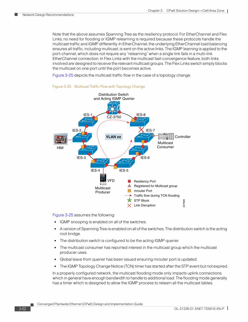
Chapter 3 CPwE Solution Design—Cell/Area Zone
Network Design Recommendations
Note that the above assumes Spanning Tree as the resiliency protocol. For EtherChannel and Flex Links, no need for flooding or IGMP relearning is required because these protocols handle the multicast traffic and IGMP differently. In EtherChannel, the underlying EtherChannel load balancing ensures all traffic, including multicast, is sent on the active links. The IGMP learning is applied to the port-channel, which does not require any “relearning” when a single link fails in a multi-link EtherChannel connection. In Flex Links with the multicast fast-convergence feature, both links involved are designed to receive the relevant multicast groups. The Flex Links switch simply blocks the multicast on one port until the port becomes active.
Figure 3-25 depicts the multicast traffic flow in the case of a topology change.
Figure 3-25 Multicast Traffic Flow with Topology Change
Figure 3-25 assumes the following:
• IGMP snooping is enabled on all of the switches.
• A version of Spanning Tree is enabled on all of the switches. The distribution switch is the acting root bridge.
• The distribution switch is configured to be the acting IGMP querier.
• The multicast consumer has reported interest in the multicast group which the multicast producer uses.
• Global leave from querier has been issued ensuring mrouter port is updated.
• The IGMP Topology Change Notice (TCN) timer has started after the STP event but not expired.
In a properly configured network, the multicast flooding mode only impacts uplink connections, which in general have enough bandwidth to handle to additional load. The flooding mode generally has a timer which is designed to allow the IGMP process to relearn all the multicast tables.
VLAN xx
STP Block
Traffic flow during TCN flooding
mrouter Port
Registered for Multicast group
HMI
IES-1
IES-7IES-2
IES-8CZ-3750
Distribution Switch and Acting IGMP Querier
IES-3
IES-4 IES-5
IES-6
VFD
MuliticastProducer
MuliticastConsumer
Controller
2276
66
Link Disruption
Resiliency Port
3-62Converged Plantwide Ethernet (CPwE) Design and Implementation Guide
OL-21226-01, ENET-TD001E-EN-P
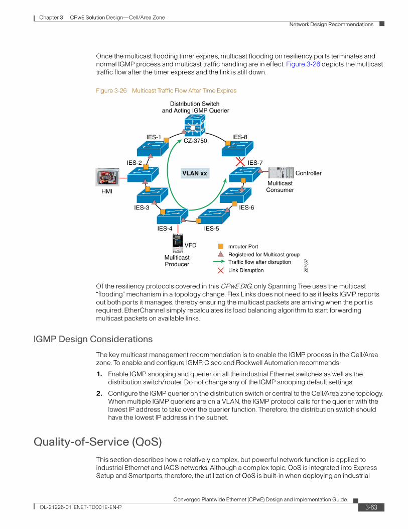
Chapter 3 CPwE Solution Design—Cell/Area Zone
Network Design Recommendations
Once the multicast flooding timer expires, multicast flooding on resiliency ports terminates and normal IGMP process and multicast traffic handling are in effect. Figure 3-26 depicts the multicast traffic flow after the timer express and the link is still down.
Figure 3-26 Multicast Traffic Flow After Time Expires
Of the resiliency protocols covered in this CPwE DIG, only Spanning Tree uses the multicast “flooding” mechanism in a topology change. Flex Links does not need to as it leaks IGMP reports out both ports it manages, thereby ensuring the multicast packets are arriving when the port is required. EtherChannel simply recalculates its load balancing algorithm to start forwarding multicast packets on available links.
IGMP Design Considerations
The key multicast management recommendation is to enable the IGMP process in the Cell/Area zone. To enable and configure IGMP, Cisco and Rockwell Automation recommends:
1. Enable IGMP snooping and querier on all the industrial Ethernet switches as well as the distribution switch/router. Do not change any of the IGMP snooping default settings.
2. Configure the IGMP querier on the distribution switch or central to the Cell/Area zone topology. When multiple IGMP queriers are on a VLAN, the IGMP protocol calls for the querier with the lowest IP address to take over the querier function. Therefore, the distribution switch should have the lowest IP address in the subnet.
Quality-of-Service (QoS)
This section describes how a relatively complex, but powerful network function is applied to industrial Ethernet and IACS networks. Although a complex topic, QoS is integrated into Express Setup and Smartports, therefore, the utilization of QoS is built-in when deploying an industrial
VLAN xx
Traffic flow after disruption
mrouter Port
Registered for Multicast group
HMI
IES-1
IES-7IES-2
IES-8CZ-3750
Distribution Switch and Acting IGMP Querier
IES-3
IES-4 IES-5
IES-6
VFD
MuliticastProducer
MuliticastConsumer
Controller
2276
67
Link Disruption
3-63Converged Plantwide Ethernet (CPwE) Design and Implementation Guide
OL-21226-01, ENET-TD001E-EN-P

Chapter 3 CPwE Solution Design—Cell/Area Zone
Network Design Recommendations
Ethernet network following the CPwE design and implementation steps. By following these steps, a network developer will get the benefits of QoS without having to take additional steps. The detail in this section is intended to help enable a implementers to enhance or tailor the QoS for their environment, if necessary. If such changes are made, Cisco and Rockwell Automation highly recommend sufficient testing of the changes are performed to ensure the desired effect is achieved. This section describes how QoS works in general and specifies the major QoS design considerations Cisco and Rockwell Automation developed for IACS networks.
QoS refers to network control mechanisms that can provide various priorities to different IACS devices or data flows, or guarantee a certain level of performance to a data flow in accordance with requests from the application program. QoS guarantees are important if the network performance is critical, especially for real-time IACS.
Note Cisco and Rockwell Automation recommend the application of QoS to the critical CIP Implicit I/O as well as the Explicit message traffic generated by IACS network devices.
As indicated in “Traffic Flows” section on page 3-19, non-CIP traffic (such as Internet HTTP) is highly likely on any IACS network. The IACS devices can support various traffic types natively, and certain functions (for example, monitoring) are implemented using common protocols. Also, Level 3 workstations and servers in the Manufacturing zone produce traffic of various types that may mix with the Cell/Area IACS network traffic. It is even possible to deploy voice and video into a Cell/Area IACS network, as they are based upon standard networking technologies. Manufacturers may want to take advantage of the openness that standard networks provide to introduce other services into the Manufacturing zone, without sacrificing the performance required by the IACS. QoS is a key mechanism to achieve this goal.
Beyond the performance implications, QoS also provides the following:
• Security, by placing priority on IACS device data, IACS networks are less-susceptible to a variety of attacks, especially denial-of-service (DoS) attacks on the network.
• Bandwidth utilization optimization by matching applications to the amount of bandwidth they receive in the network in times of congestion.
For this version of the CPwE solution architecture, Cisco and Rockwell Automation did not specifically test QoS settings or verify the benefits. However, as the ODVA has integrated end-device QoS into the EtherNet/IP specification and the Cisco and Rockwell Automation industrial Ethernet switches apply a QoS approach in the standard configuration and deployment, some background and design consideration is included here.
This section covers the basic concepts related to applying QoS in an IACS Cell/Area zone, including the following:
• QoS Background
• QoS Objectives and Application Service Level
• End-to-End Service Levels
• Identification and Marking
• Policing, Queuing and Scheduling
3-64Converged Plantwide Ethernet (CPwE) Design and Implementation Guide
OL-21226-01, ENET-TD001E-EN-P
Chapter 3 CPwE Solution Design—Cell/Area Zone
Network Design Recommendations
QoS Background
QoS refers to the capability of a network to provide better service to selected network traffic. The primary goal of QoS is to provide priority including dedicated bandwidth, controlled jitter and latency (required by some real-time and interactive traffic), and improved loss characteristics. This applies especially to the IACS network traffic. Also important is making sure that providing priority for one or more flows does not make other flows fail.
For more background on QoS, the following readings are recommended:
• Enterprise QoS Solution Guide— http://www.cisco.com/en/US/docs/solutions/Enterprise/WAN_and_MAN/QoS_SRND/QoSIntro.html
• Internetworking Technology Handbook, Quality of Service— http://www.cisco.com/en/US/tech/tk1330/tsd_technology_support_technical_reference_chapter09186a0080759886.html
• IE 3000 Software Configuration Guide, Configuring QoS— http://www.cisco.com/en/US/docs/switches/lan/cisco_ie3000/software/release/12.2_50_se/configuration/guide/swqos.html#wp1284809
The discussion in this chapter is based on the basic QoS concepts outlined in the above documents.
QoS Objectives and Application Service Level
To apply QoS onto a network infrastructure, objectives, and application service levels are required. Each organization deploying a standard Ethernet and IP network for the plant floor should have an agreed upon set of objectives and application service levels that will drive the QoS approach, design, and configuration.
As stated earlier, in a IACS network, the IACS applications take precedence over other applications and traffic types as they directly impact key business metrics: uptime, efficiency and performance. The design and implementation of QoS in the industrial Ethernet switches was based on the following objectives aligned with the key business metrics:
• IACS network traffic should take priority over other applications (e.g. web-based, voice or video) in the Cell/Area zone.
• IACS network traffic tends to be very sensitive to latency, jitter and packet loss. The Service Level for IACS network traffic should minimize these.
• Different types of industrial Ethernet traffic (Motion, I/O, and HMI) have different requirements for latency, packet loss, and jitter. The service policy should differentiate service for these types of flows.
• The network developer would like non-IACS traffic (HTTP, E-mail, etc.) to have little or no affect on the IACS application.
Table 3-10 depicts the relative sensitivities of IACS network traffic versus typical Enterprise network traffic.
Since the original version of this solution, the ODVA has published standards that incorporate QoS marking by end-devices. These guidelines specify the markings for both Layer-3 QoS field (DSCP) and Layer 2 (class-of-service). These guidelines also establish relative priority for various types of IACS network traffic.
3-65Converged Plantwide Ethernet (CPwE) Design and Implementation Guide
OL-21226-01, ENET-TD001E-EN-P
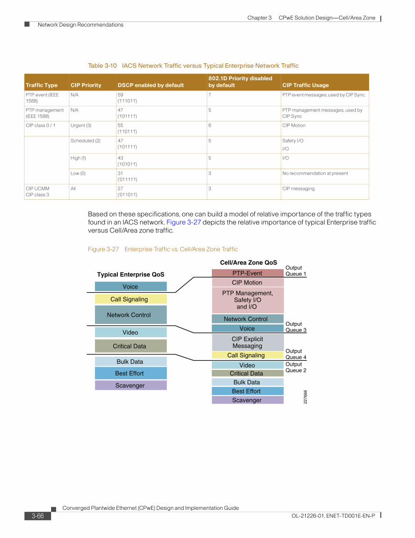
Chapter 3 CPwE Solution Design—Cell/Area Zone
Network Design Recommendations
Based on these specifications, one can build a model of relative importance of the traffic types found in an IACS network. Figure 3-27 depicts the relative importance of typical Enterprise traffic versus Cell/Area zone traffic.
Figure 3-27 Enterprise Traffic vs. Cell/Area Zone Traffic
Table 3-10 IACS Network Traffic versus Typical Enterprise Network Traffic
Traffic Type CIP Priority DSCP enabled by default
802.1D Priority disabled
by default CIP Traffic Usage
PTP event (IEEE
1588)
N/A 59
(‘111011’)
7 PTP event messages, used by CIP Sync
PTP management
(IEEE 1588)
N/A 47
(‘101111’)
5 PTP management messages, used by
CIP Sync
CIP class 0 / 1 Urgent (3) 55
(‘110111’)
6 CIP Motion
Scheduled (2) 47
(‘101111’)
5 Safety I/O
I/O
High (1) 43
(‘101011’)
5 I/O
Low (0) 31
(‘011111’)
3 No recommendation at present
CIP UCMM
CIP class 3
All 27
(‘011011’)
3 CIP messaging
Critical Data
Video
Call Signaling
Best Effort
Voice
Bulk Data
Network Control
Scavenger
Critical DataVideo
Call Signaling
Best Effort
Voice
Bulk Data
Network Control
Scavenger
CIP ExplicitMessaging
CIP Motion
PTP Management,Safety I/Oand I/O
Typical Enterprise QoS
Cell/Area Zone QoS
OutputQueue 3
OutputQueue 4 OutputQueue 2
OutputQueue 1
2276
68
PTP-Event
3-66Converged Plantwide Ethernet (CPwE) Design and Implementation Guide
OL-21226-01, ENET-TD001E-EN-P
Chapter 3 CPwE Solution Design—Cell/Area Zone
Network Design Recommendations
End-to-End Service Levels
Service levels refer to the actual end-to-end QoS capabilities, meaning the capability of a network to deliver service needed by specific network traffic from end-to-end or edge-to-edge. The services differ in their level of QoS strictness, which describes how tightly the service can be bound by specific bandwidth, delay, jitter, and loss characteristics.
Three basic levels of end-to-end QoS can be provided across a heterogeneous network:
• Best-effort service—Also known as lack of QoS, best-effort service is basic connectivity with no guarantees. This is best characterized by FIFO queues, which have no differentiation between flows.
• Differentiated service (also called soft QoS)—Some traffic is treated better than the rest (faster handling, more average bandwidth, and lower average loss rate). This is a statistical preference, not a hard and fast guarantee. This is provided by classification of traffic and the use of QoS tools such as priority queuing, Weighted Tail Drop (WTD) for queue buffer management, and shaped round-robin for queue servicing (see the referenced QoS documentation listed under the “QoS Background” section on page 3-65).
• Guaranteed service (also called hard QoS)—This is an absolute reservation of network resources for specific traffic. This is provided through various QoS tools.
Deciding which type of service is appropriate to deploy in the network depends on several factors:
• The application or problem to be solved. Each of the three types of service is appropriate for certain applications. This does not imply mandatory migration to differentiated services and then to guaranteed service. A differentiated service—or even a best-effort service—may be appropriate, depending on the IACS application requirements.
• The rate at which manufacturers can realistically upgrade their infrastructures. There is a natural upgrade path from the technology needed to provide differentiated services to that needed to provide guaranteed services, which is a superset of that needed for differentiated services.
• The cost of implementing and deploying guaranteed service is likely to be more than that for a differentiated service.
Typically, IACS networks have been best-effort service levels, as typically they carry limited amounts and types of traffic. But as the use of standard Ethernet and IP networking spreads in the plant and as that IACS networking is used for more applications, a different model will be required.
Note Cisco and Rockwell Automation recommend and implement in the standard configuration a differentiated service end-to-end in the Cell/Area zone.
The key reasons for choosing differentiated service include the following:
• Provides significant value over best-effort service as priority can be given to IACS network traffic, even prioritizing traffic flows within the application to better ensure.
• Provides flexibility to support peaks and spikes in bandwidth utilization by providing available network resources to those applications, while maintaining service to IACS network devices.
• IACS network traffic is generally not bandwidth intensive where they need specific amounts of the bandwidth guaranteed.
• Set once and left to operate without significant operational interaction. The differentiated services does not require updating or modification when new applications are introduced, although some modification may be required if the service policy is updated as applications are added.
3-67Converged Plantwide Ethernet (CPwE) Design and Implementation Guide
OL-21226-01, ENET-TD001E-EN-P
Chapter 3 CPwE Solution Design—Cell/Area Zone
Network Design Recommendations
Identification and Marking
The first element to a QoS policy is to classify/identify the traffic that is to be treated differently. Classification and marking tools set this trust boundary by examining any of the following:
• Layer 2 parameters—802.1Q class-of-service (CoS) bits
• Layer 3 parameters—IP Precedence (IPP), Differentiated Services Code Points (DSCP), IP Explicit Congestion Notification (ECN), source/destination IP address
• Layer 4 parameters— L4 protocol (TCP/UDP), source/destination ports
• Layer 7 parameters— application signatures
The QoS model implemented in the IE switches focuses on the Differentiated Services or DiffServ model. One of the key goals of the DiffServ is to classify and mark the traffic as close to the source as possible. This allows for an end-to-end model where intermediary routers and switches simply forward the frame based on the predetermined marking. Do not trust markings that can be set by users on their PCs or other similar devices, because users can easily abuse provisioned QoS policies if permitted to mark their own traffic.
Following classification, marking tools can set an attribute of a frame or packet to a specific value. Such marking (or remarking) establishes a trust boundary that scheduling tools later depend on. Cisco and Rockwell Automation recommend the following:
• IACS network devices designed to mark and classify traffic in accordance with the ODVA's specification should be trusted(e.g., devices conforming to ODVA's CIP Networks Library, Volume 2, EtherNet/IP Adaptation of CIP Edition 1.6 November 2008 where QoS was introduced and enabled to mark their traffic).
• IACS network devices that are not designed to mark their network traffic (should not be trusted and the network infrastructure should classify and mark the ingress traffic from such devices. In this way, the traffic from legacy devices receives respective network priority even if newer, QoS-compliant devices exist in the network.
• Network uplinks and inter-switch connections are QoS trusted ports.
For the Cell/Area zone, the trust/no-trust can be depicted in Figure 3-28.
3-68Converged Plantwide Ethernet (CPwE) Design and Implementation Guide
OL-21226-01, ENET-TD001E-EN-P
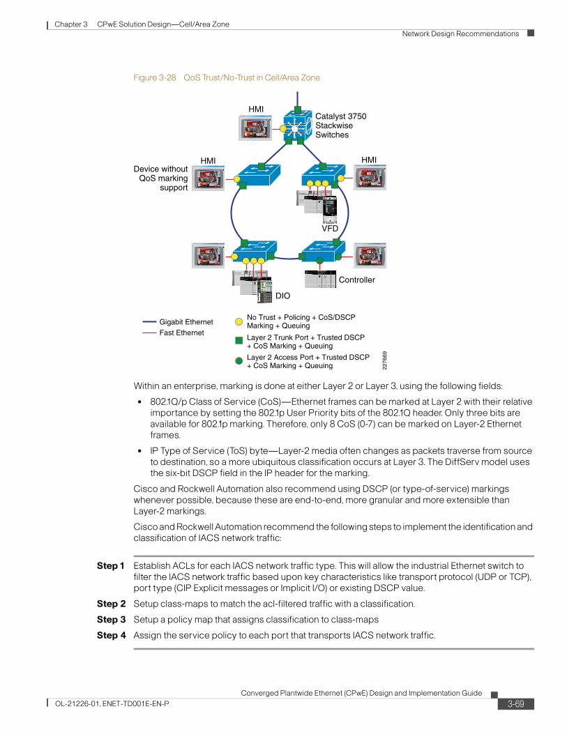
Chapter 3 CPwE Solution Design—Cell/Area Zone
Network Design Recommendations
Figure 3-28 QoS Trust/No-Trust in Cell/Area Zone
Within an enterprise, marking is done at either Layer 2 or Layer 3, using the following fields:
• 802.1Q/p Class of Service (CoS)—Ethernet frames can be marked at Layer 2 with their relative importance by setting the 802.1p User Priority bits of the 802.1Q header. Only three bits are available for 802.1p marking. Therefore, only 8 CoS (0-7) can be marked on Layer-2 Ethernet frames.
• IP Type of Service (ToS) byte—Layer-2 media often changes as packets traverse from source to destination, so a more ubiquitous classification occurs at Layer 3. The DiffServ model uses the six-bit DSCP field in the IP header for the marking.
Cisco and Rockwell Automation also recommend using DSCP (or type-of-service) markings whenever possible, because these are end-to-end, more granular and more extensible than Layer-2 markings.
Cisco and Rockwell Automation recommend the following steps to implement the identification and classification of IACS network traffic:
Step 1 Establish ACLs for each IACS network traffic type. This will allow the industrial Ethernet switch to filter the IACS network traffic based upon key characteristics like transport protocol (UDP or TCP), port type (CIP Explicit messages or Implicit I/O) or existing DSCP value.
Step 2 Setup class-maps to match the acl-filtered traffic with a classification.
Step 3 Setup a policy map that assigns classification to class-maps
Step 4 Assign the service policy to each port that transports IACS network traffic.
2276
69
Catalyst 3750StackwiseSwitches
Device withoutQoS marking
support
HMI HMI
HMI
Controller
DIO
Fast Ethernet
Layer 2 Access Port + Trusted DSCP+ CoS Marking + Queuing
Layer 2 Trunk Port + Trusted DSCP+ CoS Marking + Queuing
No Trust + Policing + CoS/DSCPMarking + QueuingGigabit Ethernet
VFD
3-69Converged Plantwide Ethernet (CPwE) Design and Implementation Guide
OL-21226-01, ENET-TD001E-EN-P
Chapter 3 CPwE Solution Design—Cell/Area Zone
Network Design Recommendations
Note Due to potential compatibility issues with some IACS devices, the current network infrastructure configuration does not re-write DSCP markings. The network infrastructure must apply the IACS service policy at each hop in the Cell/Area zone.
The following applies to implement DSCP marking:
• Determine whether the IACS devices are capable of receiving DSCP marked packets.
• Test that the QoS changes have no unexpected changes.
• Prepare to change the global settings in each Cell/Area zone switch to write DSCP field for un-trusted devices (change the no rewrite DSCP command) and update uplink port settings to trust DSCP (versus CoS) and remove the service policy.
Policing, Queuing and Scheduling
This section describes the key tools the network infrastructure can apply and manage the priority and service a packet receives after it has been identified and classified. These tools include the following
• Policing traffic types for bandwidth over-utilization
• Queuing the traffic in ingress and egress queue buffers
• Scheduling traffic to be processed once it is in a queue
After a brief discussion of each of these QoS tools, we make recommendations of how these should be applied and outline some of the key settings in reference tables.
Policing
Policing is a mechanism to limit the bandwidth of any traffic class and can be used on any port. Policing, if applied, is executed after a packet is classified. Policing can result in three actions:
1. No action if the bandwidth is not exceeded.
2. If the bandwidth is exceeded, the packet may be dropped.
3. If the bandwidth is exceeded, the packet may be “marked down” where the classification is modified to presumably lower its priority.
At this point in time, Cisco and Rockwell Automation do not recommend applying any bandwidth policing on IACS networks traffic, nor applying any non-default policing to other traffic types. As other traffic types are handled by other queues, the bandwidth they consume will be restricted via queue buffer management and scheduling. Voice traffic, if it exists, has default police settings.
Queuing
Queuing establishes buffers to handle packets as they arrive at the switch (ingress) and leave the switch (egress). Each port on the switch has ingress two and egress four queues. Both the ingress and egress queues use an enhanced version of the tail-drop congestion-avoidance mechanism called weighted tail drop (WTD). WTD is implemented on queues to manage the queue lengths and to provide drop precedence for different traffic classifications. Each queue has three thresholds to proactively drop packets before queues fill up. Traffic classes assigned to thresholds 1 or 2 will be dropped if the queue buffer has reached the assigned threshold. Traffic classes assigned to a threshold of 3 for a specific queue will only be dropped if that queue has filled its buffer space.
3-70Converged Plantwide Ethernet (CPwE) Design and Implementation Guide
OL-21226-01, ENET-TD001E-EN-P
Chapter 3 CPwE Solution Design—Cell/Area Zone
Network Design Recommendations
To prioritize IACS network traffic, Cisco and Rockwell Automation recommend that IACS network traffic types be assigned to specific queues which are given preferential buffer space, bandwidth and scheduling treatment.
To avoid packet loss, Cisco and Rockwell Automation recommend that IACS network traffic types be assigned to threshold 3 of the specific queue.
Scheduling
Both the ingress and egress queues are serviced by Shared Round-Robin (SRR) scheduling, which controls the rate at which packets are sent. On the ingress queues, SRR sends packets to the internal ring. On the egress queues, SRR sends packets to the egress port.
Cisco and Rockwell Automation recommend mapping marked IACS traffic (see the “Identification and Marking” section on page 3-68) to specific ingress and egress queues so as to manage the packet loss (avoid dropping) and to give preferential treatment via preferred scheduling via bandwidth percentage assignments to each queue.
Cisco and Rockwell Automation recommend using shared-mode SRR scheduling so as to use available bandwidth, yet guarantee the assigned bandwidth is available to that queue during congestion. This is opposed to using shaped-mode which rate-limits a queue to its assigned percentage of bandwidth.
To apply this recommendation, complete the following steps:
Step 1 Enable priority queue out (queue 1) on all switch ports carrying IACS network traffic (access and trunk ports). This ensures the highest priority traffic assigned to the queue will be serviced quickly. This queue will no longer be serviced as a shared round-robin and any SRR settings for that port will not be in effect.
Step 2 Assign specific queues for IACS network traffic and other priority traffic, if it exists (e.g. Voice and Network Routing traffic). These queues are then assigned buffers and scheduling weights to minimize packet loss and optimize scheduling. Maintain 1 ingress and egress queue for other traffic. For ingress, queue 1 is for other traffic. For egress, queue 2 (of 4) is for best effort traffic.
Step 3 Map IACS network traffic to specific queues via CoS and DSCP maps for each queue and threshold. IACS network traffic should be assigned to the third threshold to avoid packet loss. Packet loss will occur if the queues buffers are full, but not until then. The queue that they are assigned to will define the minimum amount of bandwidth they receive and will define how quickly they are serviced, where the priority queue is always handled first.
Step 4 Assign SRR Queue bandwidth share weightings for all ports to assign weights to the egress queues for that port. This represents the relative amount of bandwidth dedicated to traffic in a queue when congestion occurs. When a queue is not using its bandwidth, the bandwidth is made available to other queues.
Step 5 Define output/egress queue buffers sets that are assigned to a port to allocate the buffer space to a queue. By allocating more queue space to IACS network traffic queues, packet-loss is avoided.
The above settings allow for specific priority to be assigned to CIP network traffic while maintaining a basic service for other types of traffic. These settings are aligned with the ODVA's recommendations for QoS and ensure that IACS devices that cannot mark their own CIP traffic receive the same preferential QoS treatment as IACS devices that mark their CIP traffic. No specific configuration is required to apply these QoS recommendations to the Cisco and Rockwell Automation industrial Ethernet switch beyond using Express Setup and selecting the appropriate Smartport as noted in Chapter 5, “Implementing and Configuring the Cell/Area Zone.”
3-71Converged Plantwide Ethernet (CPwE) Design and Implementation Guide
OL-21226-01, ENET-TD001E-EN-P
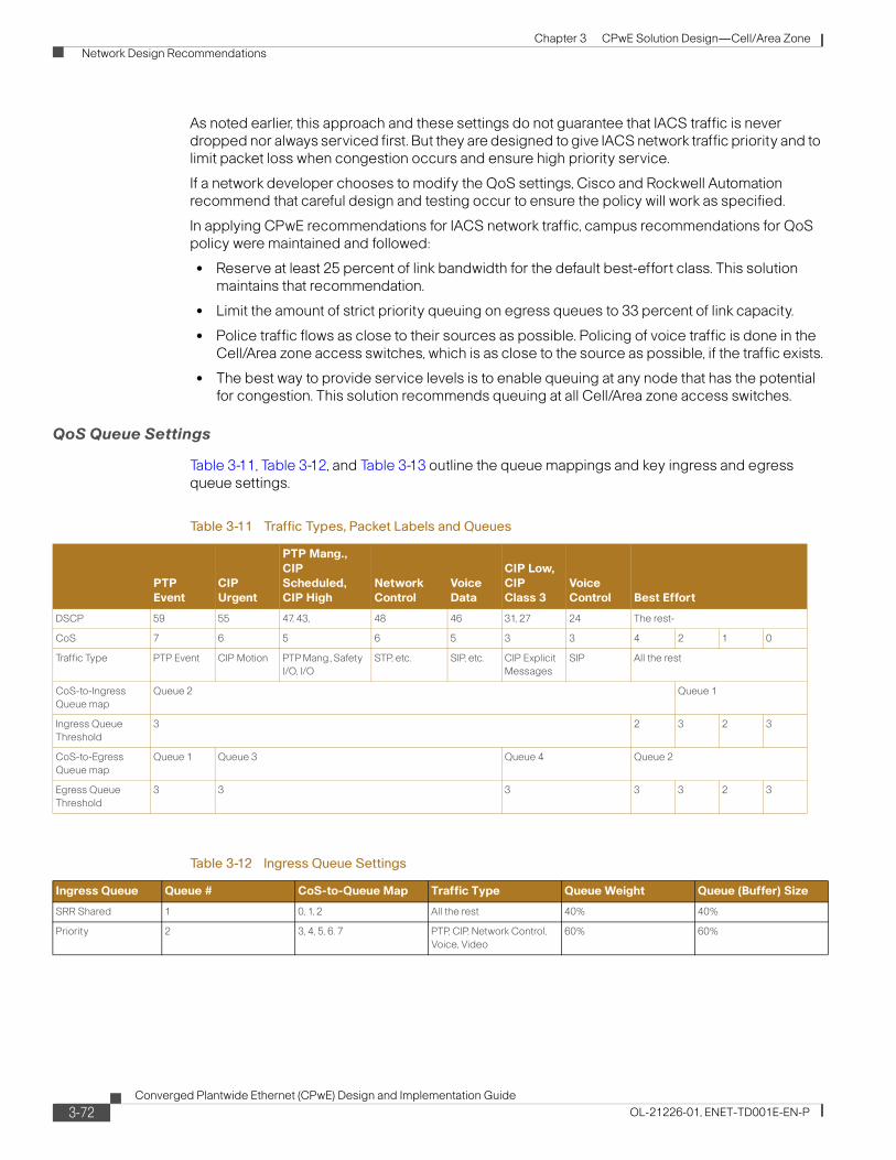
Chapter 3 CPwE Solution Design—Cell/Area Zone
Network Design Recommendations
As noted earlier, this approach and these settings do not guarantee that IACS traffic is never dropped nor always serviced first. But they are designed to give IACS network traffic priority and to limit packet loss when congestion occurs and ensure high priority service.
If a network developer chooses to modify the QoS settings, Cisco and Rockwell Automation recommend that careful design and testing occur to ensure the policy will work as specified.
In applying CPwE recommendations for IACS network traffic, campus recommendations for QoS policy were maintained and followed:
• Reserve at least 25 percent of link bandwidth for the default best-effort class. This solution maintains that recommendation.
• Limit the amount of strict priority queuing on egress queues to 33 percent of link capacity.
• Police traffic flows as close to their sources as possible. Policing of voice traffic is done in the Cell/Area zone access switches, which is as close to the source as possible, if the traffic exists.
• The best way to provide service levels is to enable queuing at any node that has the potential for congestion. This solution recommends queuing at all Cell/Area zone access switches.
QoS Queue Settings
Table 3-11, Table 3-12, and Table 3-13 outline the queue mappings and key ingress and egress queue settings.
Table 3-11 Traffic Types, Packet Labels and Queues
PTP Event
CIP Urgent
PTP Mang.,
CIP
Scheduled, CIP High
Network Control
Voice Data
CIP Low,
CIP Class 3
Voice Control Best Effort
DSCP 59 55 47, 43, 48 46 31, 27 24 The rest-
CoS 7 6 5 6 5 3 3 4 2 1 0
Traffic Type PTP Event CIP Motion PTP Mang., Safety
I/O, I/O
STP, etc. SIP, etc. CIP Explicit
Messages
SIP All the rest
CoS-to-Ingress
Queue map
Queue 2 Queue 1
Ingress Queue
Threshold
3 2 3 2 3
CoS-to-Egress
Queue map
Queue 1 Queue 3 Queue 4 Queue 2
Egress Queue
Threshold
3 3 3 3 3 2 3
Table 3-12 Ingress Queue Settings
Ingress Queue Queue # CoS-to-Queue Map Traffic Type Queue Weight Queue (Buffer) Size
SRR Shared 1 0, 1, 2 All the rest 40% 40%
Priority 2 3, 4, 5, 6. 7 PTP, CIP, Network Control,
Voice, Video
60% 60%
3-72Converged Plantwide Ethernet (CPwE) Design and Implementation Guide
OL-21226-01, ENET-TD001E-EN-P
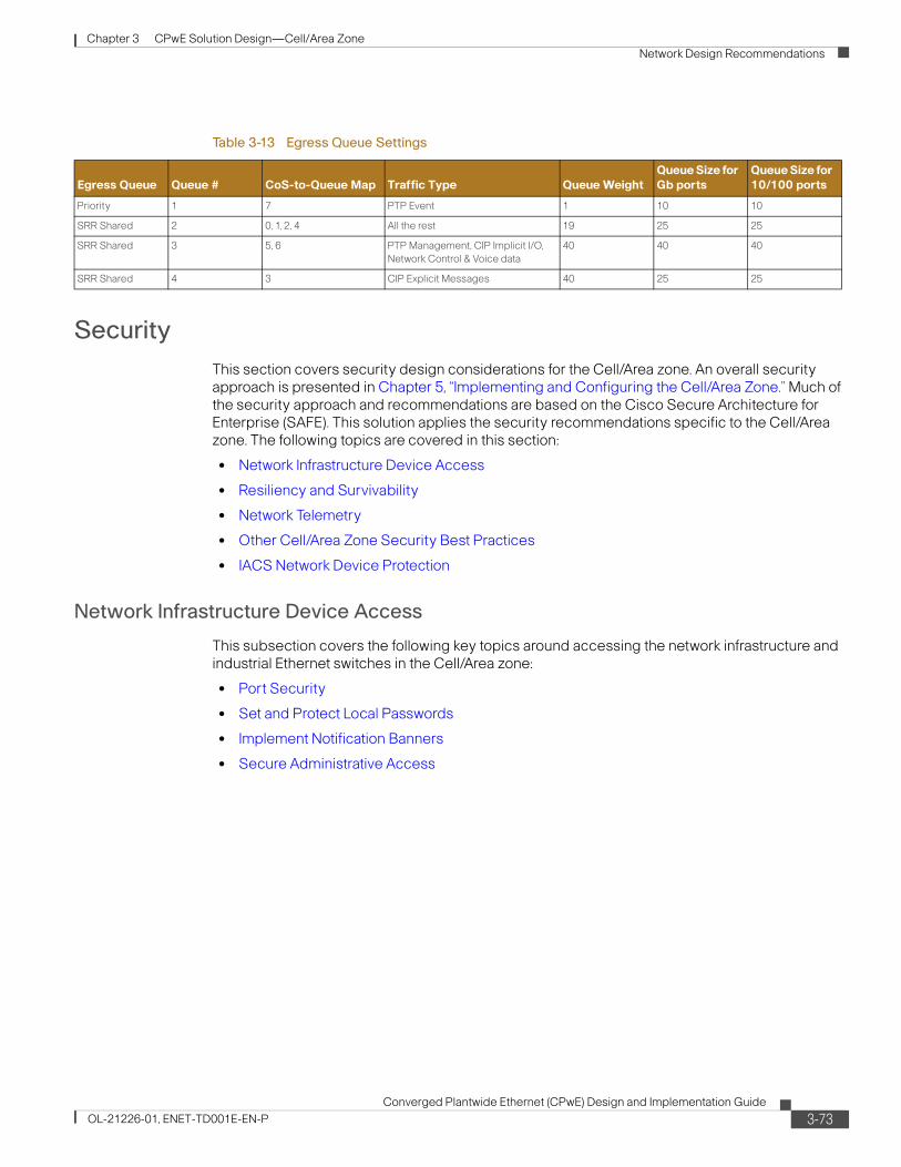
Chapter 3 CPwE Solution Design—Cell/Area Zone
Network Design Recommendations
Security
This section covers security design considerations for the Cell/Area zone. An overall security approach is presented in Chapter 5, “Implementing and Configuring the Cell/Area Zone.” Much of the security approach and recommendations are based on the Cisco Secure Architecture for Enterprise (SAFE). This solution applies the security recommendations specific to the Cell/Area zone. The following topics are covered in this section:
• Network Infrastructure Device Access
• Resiliency and Survivability
• Network Telemetry
• Other Cell/Area Zone Security Best Practices
• IACS Network Device Protection
Network Infrastructure Device Access
This subsection covers the following key topics around accessing the network infrastructure and industrial Ethernet switches in the Cell/Area zone:
• Port Security
• Set and Protect Local Passwords
• Implement Notification Banners
• Secure Administrative Access
Table 3-13 Egress Queue Settings
Egress Queue Queue # CoS-to-Queue Map Traffic Type Queue Weight
Queue Size for
Gb ports
Queue Size for
10/100 ports
Priority 1 7 PTP Event 1 10 10
SRR Shared 2 0, 1, 2, 4 All the rest 19 25 25
SRR Shared 3 5, 6 PTP Management, CIP Implicit I/O,
Network Control & Voice data
40 40 40
SRR Shared 4 3 CIP Explicit Messages 40 25 25
3-73Converged Plantwide Ethernet (CPwE) Design and Implementation Guide
OL-21226-01, ENET-TD001E-EN-P
Chapter 3 CPwE Solution Design—Cell/Area Zone
Network Design Recommendations
Port Security
Access to the network starts with physically accessing ports on switches. There are a number of techniques to limit the ability to access the network.
First, network access cannot be achieved if the network devices are physically secure with limited access. Placing the industrial Ethernet switches in locked rooms, cabinets, or even by buying port locks to close unused ports on a switch are all recommended best practices by Cisco and Rockwell Automation. Further, industrial Ethernet switches themselves can be configured to secure their ports from unknown access or miss-use. Switch port security limits the access to the network by unknown devices and limits the number of devices or MAC addresses on any network port. Port security builds a list of secure MAC addresses in one of two following ways, configurable on a per-interface basis:
• Dynamic learning of MAC addresses—Defines a maximum number of MAC addresses that will be learnt and permitted on a port. Useful for dynamic environments, such as at the access edge.
• Static configuration of MAC addresses—Defines the static MAC addresses permitted on a port. Useful for static environments, such as a server farm, a lobby, or a Demilitarized Network (DMZ).
Although some implementers may consider static MAC address configurations per-port for environments that need very high security, this method requires significant maintenance work where ports may need modification by network experts to perform normal maintenance tasks such as replacing a failed device. Therefore, Cisco and Rockwell Automation recommend application of the dynamic learning to limit the number devices that can access a port. This allows, for example, only one MAC address to access an IACS network port on the industrial Ethernet switch.
The Error Disable feature helps protect the switch and therefore the network from certain error conditions, for example when the number of MAC addresses on a port is exceeded. When the error condition is discovered, the interface is put into the error disable state and does not pass traffic. Cisco and Rockwell Automation recommend that the errdisable recovery interval seconds global configuration command be used to restore the port. This command will periodically check to see if the error condition still exists on the interface. The interface will automatically be enabled when the error condition has cleared.
Additionally, Cisco and Rockwell Automation recommend that all unused ports be disabled and only enabled when required.
Set and Protect Local Passwords
Global password encryption, local user-password encryption, and enable secret are features available in the industrial Ethernet switches to help secure locally stored sensitive information. Cisco and Rockwell Automation recommend the following:
• Enable automatic password encryption. Once configured, all passwords are encrypted automatically, including passwords of locally defined users.
• Define a local enable password using the enable secret global command.
• Define a line password with the password line command for each line you plan to use to administer the system.
In many enterprise environments, Authentication, Authorization and Accounting (AAA) is the method for access control to network infrastructure. This framework may be implemented for highly secure environments, but this method is more operationally challenging than the security
3-74Converged Plantwide Ethernet (CPwE) Design and Implementation Guide
OL-21226-01, ENET-TD001E-EN-P
Chapter 3 CPwE Solution Design—Cell/Area Zone
Network Design Recommendations
requirements call for. If used though, Cisco and Rockwell Automation recommends TACACS+ (vs. RADIUS) when it comes to device administration. TACACS+ supports command authorization, allowing the control of which command can be executed on a device and which cannot.
Implement Notification Banners
Cisco and Rockwell Automation recommend that a legal notification banner login is presented on all interactive sessions to ensure that users are notified of the security policy being enforced and to which they are subject.
Secure Administrative Access
Cisco and Rockwell Automation and recommend the following best practices for securing administrative access:
• Enable SSH1 access when available rather than the unsecured Telnet. Use at a minimum 768-bit modulus size. This feature requires AAA or local accounts as specified in industrial Ethernet switch configuration guidelines (http://www.cisco.com/en/US/docs/switches/lan/cisco_ie3000/software/release/12.2_50_se/configuration/guide/swauthen.html#wp1227177).
• Avoid HTTP access. If possible use HTTPS instead of clear-text HTTP.
• Per-used line, explicitly define the protocols allowed for incoming and outgoing sessions. Restricting outgoing sessions prevent the system from being used as a staging host for other attacks.
• Set idle and session timeouts—Set idle and session timeouts in every used line. Enable TCP keepalives to detect and close hung sessions.
• Log and account for all access.
Resiliency and Survivability
This subsection presents the following collection of best practices destined to preserve the resiliency and survivability of switches and network services, helping the network and the IACS maintain availability even during the execution of an attack:
• Disable Unnecessary Services
• Port Security (as discussed previously)
• Redundancy
1. SSH and SNMP v3 require the cryptographic (K9) version of IOS on the Cisco IE 3000 and Allen-Bradley Stratix 8000 industrial Ethernet switches. Some cryptographic features are subject to additional export and contract restrictions. For more information about export trade restrictions, see http://www.cisco.com/web/about/doing_business/legal/global_export_trade/index.html for the IE 3000 or contact your Rockwell Automation sales representative or distributor for details for the Stratix 8000.
3-75Converged Plantwide Ethernet (CPwE) Design and Implementation Guide
OL-21226-01, ENET-TD001E-EN-P
Chapter 3 CPwE Solution Design—Cell/Area Zone
Network Design Recommendations
Disable Unnecessary Services
Switches come out of the box with a list of services turned on that are considered appropriate for most network environments.
Disabling these unnecessary services has two benefits: it helps preserve system resources and eliminates the potential of security exploits on the disabled services.
Cisco and Rockwell Automation recommend the following best practices:
• Global services disabled by default—Unless explicitly needed, ensure finger, identification (identd), and TCP and UPD small servers remain disabled on all routers and switches.
• Global services enabled by default—Unless explicitly needed, BOOTP, IP source routing, and PAD services should be disabled globally on all routers.
• IP directed broadcast—Ensure directed broadcasts remain disabled on all interfaces except those required for access by RSLinx Data Servers to browse for known or available IACS EtherNet/IP devices.
• When to disable CDP—Disable CDP on interfaces where the service may represent a risk; for example, on external interfaces such as those at the Internet edge, and data-only ports at the campus and branch access.
• Access ports—Unless required disable MOP, IP redirects, and Proxy ARP on all access ports.
Redundancy
Networks are built out of numerous hardware and software components that may fail or that may be subject to attacks. Implementing redundant designs helps eliminate single points-of-failure, improving the availability of the network and making it more resistant to attacks. In the Cell/Area zone, there is a limit to how much redundancy can be implemented as most IACS network devices have only a single network interface.
The CPwE architecture is built with a wide range of options for redundancy:
• Backup and redundant uplink interfaces
• Element redundancy—Use of stacked or redundant switches in the distribution layer
• Standby devices— Active-standby and active-active failover is recommended for distribution layer in the case stacking is not an option.
• Topological redundancy—Designs built with redundant paths at both network and data-link layers. See “Topology Options and Media Considerations” section on page 3-21.
Network Telemetry
Telemetry is a word used in a number of contexts, and in this case it is used in both IT and IACS, with different connotations. This section covers the concept of network telemetry or the capability of automatically transmitting or retrieving data about the network infrastructure status and processing that information at a remote server or device. In other words, collecting and analyzing network infrastructure operational data.
In order to operate and ensure availability of a network, it is critical to have visibility and awareness into what is occurring on the network at any given time. Network telemetry offers extensive and useful detection capabilities that can be coupled with dedicated analysis systems to collect, trend, and correlate observed activity.
This subsection covers the following
3-76Converged Plantwide Ethernet (CPwE) Design and Implementation Guide
OL-21226-01, ENET-TD001E-EN-P
Chapter 3 CPwE Solution Design—Cell/Area Zone
Network Design Recommendations
• Time Synchronization
• Local Device Statistics
• Network Device Status Information
• System Logging
• Simple Network Management Protocol (SNMP)
Time Synchronization
Time synchronization is critical for event analysis and correlation, thus enabling Network Time Protocol (NTP) or Precision Time Protocol (PTP) on all infrastructure components is a fundamental requirement. Timestamps are contained on system messages and within system logs. Timestamps are needed to properly analyze and understand events that occur within the network infrastructure by providing time sequence. Cisco and Rockwell Automation recommends a time synchronization function is installed in the Manufacturing zone extending to the Cell/Area zone.
For more on implementing NTP, see Time synchronization in the Cisco SAFE Reference Guide or the TP Best Practice whitepaper (http://www.cisco.com/en/US/tech/tk869/tk769/technologies_white_paper09186a0080117070.shtml). Design and implementation of PTP is not covered in the scope of this CPwE DIG.
Cisco and Rockwell Automation recommend that a time synchronization service is implemented in the Manufacturing zone and extends to the Cell/Area zones.
Local Device Statistics
Local device statistics are the most basic and ubiquitous form of telemetry available. They provide baseline information such as per-interface throughput and bandwidth statistics, enabled features and global per-protocol traffic statistics. Key statistics to track include:
• Per-interface statistics which include throughput Packets Per Second (PPS) and Bandwidth Per Second (BPS) information.
• Per-interface IP features provides information about the IP features configured on an interface on Layer-3 switches and routers.
• Global IP statistics, including per-protocol counts for ICMP, TCP, UDP, and multicast traffic on Layer-3 switches and routers.
For more information on the statistics and information to track on industrial Ethernet switches, see the “Local Device Statistics” section in “Chapter 2, Network Foundation Protection” of the Cisco SAFE Reference Guide at the following URL:
http://www.cisco.com/en/US/docs/solutions/Enterprise/Security/SAFE_RG/chap2.html
Cisco and Rockwell Automation recommend that the local device statistics is regularly monitored.
Network Device Status Information
The Industrial Ethernet switches themselves provide a wide range of statistics and alarms on their own status. Key information includes:
• Memory, CPU, and processes providing a basic overview of the switch health and current state
• Memory and CPU threshold notifications to alarm when the state of the switch is out of normal ranges and action may be needed
3-77Converged Plantwide Ethernet (CPwE) Design and Implementation Guide
OL-21226-01, ENET-TD001E-EN-P
Chapter 3 CPwE Solution Design—Cell/Area Zone
Network Design Recommendations
For more information on the statistics and information to track on industrial Ethernet switches, see the “System Status Information” section in “Chapter 2, Network Foundation Protection of the Cisco SAFE Reference Guide at the following URL:
http://www.cisco.com/en/US/docs/solutions/Enterprise/Security/SAFE_RG/chap2.html
Cisco and Rockwell Automation recommend that the network device status information is regularly monitored and acted upon when thresholds are exceeded.
System Logging
Syslog provides invaluable operational information, including system status, traffic statistics, and device access information. For this reason, syslog is recommended on all network devices.
Follow these practices when enabling syslog:
Step 1 Enable timestamps for debugging and logging messages. Adding timestamps to messages facilitates analysis and correlation.
Step 2 Enable system message logging to a local buffer. This allows accessing the logging information directly from the router or switch in case of communication failure with the syslog server. It is important to note that local buffers are circular in nature so that newer messages overwrite older messages after the buffer is filled.
Step 3 Set the severity level of messages to be logged. Messages at or numerically lower than the specified level are logged. With respect to the severity level, the more information is logged the better; therefore, logging messages of all severity levels would be ideal. However, this may result in an overwhelming volume of messages. A good practice is to enable more detailed logging on critical systems or systems that may be more accessible to external or remote users, and only log critical alerts for the rest of the infrastructure.
Step 4 Set the source IP address of syslog messages to the address of an administrative loopback interface or, if in use the out-of-band interface.
Step 5 Disable the logging of messages to the console. This helps keep the console free of messages.
For more information on the statistics and information to track on industrial Ethernet switches, refer to the “System Logging section in “Chapter 2, Network Foundation Protection of the Cisco SAFE Reference Guide at the following URL:
http://www.cisco.com/en/US/docs/solutions/Enterprise/Security/SAFE_RG/chap2.html
Also refer to the Best Practices for IOS Switches at the following URL: (http://www.cisco.com/en/US/products/hw/switches/ps700/products_white_paper09186a00801b49a4.shtml#cg22).
Simple Network Management Protocol (SNMP)
SNMP is the protocol used by most IT organizations to monitor and manage a network infrastructure, servers and even in some cases end-devices. SNMP provides a standardized framework and a common language used for the monitoring and management of devices in a network. Although there are other protocols and means to perform the basic network management, SNMP is the most sophisticated and developed standardized protocol for this explicit purpose. Cisco and Rockwell Automation consider it a best practice to use tools and applications that use SNMP and therefore it should be enabled throughout the network infrastructure.
3-78Converged Plantwide Ethernet (CPwE) Design and Implementation Guide
OL-21226-01, ENET-TD001E-EN-P
Chapter 3 CPwE Solution Design—Cell/Area Zone
Network Design Recommendations
In case SNMP access is not required, make sure it is disabled. The no snmp-server command disables all running versions of SNMP (SNMPv1, SNMPv2C, and SNMPv3) on the device.
When SNMP is required, follow these best practices:
Step 1 Restrict what systems can access the SNMP agent running on the router or switch. Be as specific as possible, for instance, only permitting access from the SNMP management stations.
Step 2 If using SNMPv31 (recommended), enforce an SNMP view that restricts the download of full IP routing and ARP tables.
Step 3 If SNMPv3 is supported, enable only SNMP v3 and with the maximum security level supported by the SNMP managers, using encrypted communication (priv) where feasible. The engine ID of an SNMP v3 SNMP manager is required in order to enable SNMPv3.
Step 4 Set the source IP address for SNMP traps to the address used on the administrative loopback interface of out-of-band interface.
For more on SNMP configuration see Best Practices for IOS Switches (http://www.cisco.com/en/US/products/hw/switches/ps700/products_white_paper09186a00801b49a4.shtml#cg23)
Other Cell/Area Zone Security Best Practices
This section covers other security best practices relevant to the Cell/Area zone, including the following:
• Restrict Broadcast Domains
• STP Security
• VLAN Best Practices
• DHCP Protection
• ARP Spoofing Protection
• Traffic Storm Protection
Restrict Broadcast Domains
By definition, LAN switches are responsible for forwarding unknown frames, multicast frames and broadcast frames throughout the LAN segment, forming a broadcast domain. While broadcast domains facilitate Layer-2 connectivity between systems on a LAN segment, designing networks with unnecessarily large broadcast domains has potential drawbacks.
First, in large networks, the flooding of unknown, multicast and broadcast frames may degrade performance, even to the point of breaking connectivity. In addition, a broadcast domain defines a failure domain, whereby all systems and switches on the same LAN segment suffer during a failure. Therefore the larger the broadcast domain the bigger the impact of a failure. Finally, larger broadcast domains increase the chances of security incidents.
To avoid the challenges described above, it is a good practice to segment broadcast domains into multiple IP subnets or VLANs using a hierarchical, topologies or functional design. Cisco and Rockwell Automation recommend applying VLANs to restrict broadcast domains. See “VLAN Design” section on page 3-38 for more information.
1. SSH and SNMP v3 require the cryptographic (K9) version of IOS on the Cisco IE 3000 and Allen-Bradley Stratix 8000 industrial Ethernet switches. Some cryptographic features are subject to additional export and contract restrictions. For more information about export trade restrictions, see http://www.cisco.com/web/about/doing_business/legal/global_export_trade/index.html for the IE 3000 or contact your Rockwell Automation sales representative or distributor for details for the Stratix 8000.
3-79Converged Plantwide Ethernet (CPwE) Design and Implementation Guide
OL-21226-01, ENET-TD001E-EN-P
Chapter 3 CPwE Solution Design—Cell/Area Zone
Network Design Recommendations
STP Security
STP is a key aspect of this solution and is typically found in network infrastructures, often even if other resiliency protocols are in effect. There are a number of features designed to protect the functioning of this protocol. Cisco and Rockwell Automation recommend the following:
• Disable VLAN dynamic trunk negotiation trunking on IACS ports
• Use Rapid Per-VLAN Spanning Tree (RPVST+) or MSTP when using STP for resiliency or loop protection
• Configure BPDU Guard on host ports
• Configure BPDU Filter on host ports
• Configure STP Root Guard on the STP root (normally the distribution switch)
• Disable unused ports and put them into an unused VLAN
• Enable traffic storm control (see below)
VLAN Best Practices
VLAN hopping is an attack vector that provides a client with unauthorized access to other VLANs on a switch. This type of attack can be easily mitigated by applying the following best common practices recommended by Cisco and Rockwell Automation:
• Always use a dedicated native VLAN ID for all trunk ports
• Disable all unused ports and put them in an unused VLAN
• Do not use VLAN 1 for anything
• Configure all IACS-facing ports as non-trunking (DTP off)
• Explicitly configure trunking on infrastructure ports
• Set the default port status to disable
DHCP Protection
IP address allocation is an important network service that must be protected. The IP address allocation is described in the “IP Addressing” section on page 4-38. DHCP or BOOTP are most likely used at some point to give a device an IP Address at points during it’s lifetime in the IACS network. Therefore, protecting that service is an important consideration for the Cell/Area zone protection.
DHCP protection is critical to ensure that a client on a Cell/Area zone port is not able to spoof or accidentally bring up a DHCP server, nor exhaust the entire DHCP address space by using a sophisticated DHCP starvation attack. Both these attacks are addressed with the Cisco IOS DHCP snooping feature that performs two key functions to address these attacks:
• Rogue DHCP Server Protection—If reserved DHCP server responses are received on an untrusted port (such as an access port), the interface is shutdown.
• DHCP Starvation Protection—Validates that the source MAC address in the DHCP payload on an untrusted (access) interface matches the source MAC address registered on that interface.
DHCP snooping is enabled on a per-VLAN basis and all interfaces in that VLAN are untrusted by default. Consequently, an interface hosting a DHCP server must be explicitly defined as trusted.
Rockwell Automation and Cisco recommend DHCP snooping is enabled in Cell/Area zone on a per-VLAN basis and on all end-host ports.
3-80Converged Plantwide Ethernet (CPwE) Design and Implementation Guide
OL-21226-01, ENET-TD001E-EN-P
Chapter 3 CPwE Solution Design—Cell/Area Zone
Network Design Recommendations
ARP Spoofing Protection
ARP spoofing protection ensures that a client on an access edge port is not able to perform a man-in-the-middle (MITM) attack by sending a gratuitous ARP that presents its MAC address as that associated with a different IP address, such as that of the default gateway. This attack is addressed with the Cisco IOS Dynamic ARP Inspection (DAI) feature that validates that the source MAC and IP address in an ARP packet received on an untrusted interface matches the source MAC and IP address registered on that interface.
DAI is enabled on a per-VLAN basis and all interfaces in that VLAN are untrusted by default. Consequently, a device that does not use DHCP, such as the default gateway, ARP inspection must be bypassed by either explicitly defining the interface it is connected to as trusted, or creating an ARP inspection ACL to permit the source MAC and IP address of that device.
Cisco and Rockwell Automation recommend enabling DAI on IACS network VLANs and end-host ports. DAI may interfere with some IACS controller redundancy schemas using EtherNet/IP and should not be used. Controller redundancy is not covered in this version of the CPwE DIG.
Traffic Storm Protection
When a large amount of broadcast (and/or multicast) packets congest a network, the event is referred to as a broadcast storm. A storm occurs when broadcast or multicast packets flood the subnet, creating excessive traffic and degrading network performance. Storm control prevents LAN interfaces from being disrupted by these broadcast and multicast storms. Errors in the protocol-stack implementation, mistakes in network configurations, or users issuing a denial-of-service (DoS) attack can cause a storm.
Storm control (or traffic suppression) monitors packets passing from an interface to the switching bus and determines if the packet is unicast, multicast, or broadcast. The switch counts the number of packets of a specified type received within the 1-second time interval and compares the measurement with a predefined suppression-level threshold. Once the suppression-level threshold is reached, the port blocks traffic until the traffic falls below the threshold level.
Cisco and Rockwell Automation recommend storm control is enabled on end-host ports.
Storm control uses one of the following methods to measure traffic activity:
• Bandwidth as a percentage of the total available bandwidth of the port that can be used by the broadcast, multicast, or unicast traffic.
• Traffic rate in packets per second at which broadcast, multicast, or unicast packets are received.
• Traffic rate in bits per second at which broadcast, multicast, or unicast packets are received.
• Traffic rate in packets per second and for small frames. This feature is enabled globally. The threshold for small frames is configured for each interface. (Cisco IOS Release 12.2(44)SE or later).
With each method, the port blocks traffic when the rising threshold is reached. The port remains blocked until the traffic rate drops below the falling threshold (if one is specified) and then resumes normal forwarding. If the falling suppression level is not specified, the switch blocks all traffic until the traffic rate drops below the rising suppression level. In general, the higher the level, the less effective the protection against broadcast storms.
For Cell/Area zone devices, Cisco and Rockwell Automation recommend applying broadcast storm controls. Multicast and unicast controls are available, but Cisco and Rockwell do not recommend setting these unless the implementer performs sufficient testing to avoid causing unintended outages. The IE 3000 (Cisco version) of the switch has default configuration of 3 percent of port bandwidth set as the rising broadcast threshold and 1 percent as the falling threshold. These are
3-81Converged Plantwide Ethernet (CPwE) Design and Implementation Guide
OL-21226-01, ENET-TD001E-EN-P
Chapter 3 CPwE Solution Design—Cell/Area Zone
Network Design Recommendations
deemed to be sufficient to stop many broadcast storms, yet not cause unnecessary disruptions in typical plant networks. In our testing, these thresholds did not cause issues. If these settings are changed, sufficient testing should occur to avoid causing unintended outages.
The default action when storm control thresholds are reached is to drop traffic until the falling threshold is reached. Cisco and Rockwell recommend maintaining this setting. The settings allow for shutting down the port when the rising threshold is reached, in which case the port is set to error disable status, and must be manually restored (no shut) or error-disable settings set to restore the port.
In addition, the settings allow for notification when storm control thresholds are reached. Cisco and Rockwell Automation recommend that implementers use the notification capabilities to monitor when storm controls are reached so as action can be taken. SNMP and the CIP object can be used to monitor the storm control thresholds.
IACS Network Device Protection
Protecting IACS network assets requires a defense-in-depth security approach. This concept was introduced in Chapter 1, “Converged Plantwide Ethernet Overview.” This approach uses multiple layers of defense (physical and electronic) at separate levels of the CPwE logical framework by applying policies and procedures that address different types of threats. No single technology or methodology can fully secure IACS networks.
In addition to the defense-in-depth layers already discussed, securing IACS network assets require the following:
• Physical security—This limits physical access of areas, control panels, IACS devices, cabling and the control rooms and other locations to authorized personnel as well as escorting and tracking visitors and partners.
• Computer hardening—This includes patch management and antivirus software as well as removal of unused applications, protocols and services.
• Application security—This contains authentication, authorization and audit software such as FactoryTalk Security for IACS applications.
• Controller hardening—This handles change management and restrictive access.
Controller Hardening
Secure Rockwell Automation Logix™ Programmable Automation Controllers (PAC) by physical procedures, electronic design, authentication and authorization software, and change management with disaster recovery software. Best practices and general recommendations include the following:
• Physical procedure—This restricts control panel access only to authorized personnel. This can accomplished by implementing access procedures or locking the panels. Switching the PAC key switch to “RUN” helps to prevent remote configuration changes. Remote configuration changes would then require a physical key change at the PAC by onsite plant floor personnel. Unauthorized access (intentional or unintentional) would not occur until the PAC key switch is changed.
• Electronic design—Implementing the PAC CPU Lock feature denies front port access to the PAC, which prevents configuration changes.
3-82Converged Plantwide Ethernet (CPwE) Design and Implementation Guide
OL-21226-01, ENET-TD001E-EN-P
Chapter 3 CPwE Solution Design—Cell/Area Zone
Network Design Recommendations
• Authentication, authorization and audit by implementing FactoryTalk® Security—Authentication verifies a user’s identity and whether service requests originate with that user. Authorization verifies a user’s request to access a feature or PAC against a set of defined access permissions.
• Change management with disaster recovery—Use FactoryTalk® AssetCentre software to continuously monitor PAC assets with automatic version control, disaster recovery and backup, device configuration verification and real-time auditing of user actions.
Computer Hardening
For computing assets within the Cell/Area zone, implement IT best practices applied to enterprise computers. Some best practices and general recommendations include the following:
• Keep computers up-to-date on service packs and hot fixes, but disable automatic updates. Additionally, network developers should test patches before implementing them as well as schedule patching and regular network maintenance during manufacturing downtime.
• Deploy and maintain antivirus and antispyware software, but disable automatic updates and automatic scanning. Test definition updates before implementing them as well as schedule manually initiated scanning during manufacturing downtime since antispyware scanning can disrupt real-time operations. Automatic antivirus and antispyware scanning has caused data loss and downtime at some manufacturing facilities.
• Prohibit direct internet access. Implementing a Demilitarized Zone (DMZ) provides a barrier between the Manufacturing and Enterprise zones, but allows IACS applications to securely share data and services. All network traffic from either side of the DMZ terminates in the DMZ. No traffic traverses the DMZ, meaning that traffic does not directly travel between the Enterprise and Manufacturing zones.
• Implement a separate Active Directory domain/forest for the Manufacturing zone. This helps ensure availability to manufacturing assets if connectivity to the Enterprise zone is disrupted.
• Implement the following password policy settings:
– Enforce password history
– Maximum password age
– Minimum password length
– Complex password requirements
• Disable the guest account on clients and servers.
• Require that the built-in administrator account uses a complex password, has been renamed and has removed its default account description.
• Develop, and then deploy, backup and disaster recovery policies and procedures. Test backups on a regular schedule.
• Implement a change management system to archive network, controller and computer assets (e.g., clients, servers and applications).
• Use Control+Alt+Delete, along with a unique user name and password to log in.
• Protect unnecessary or infrequently used USB ports, parallel and serial interfaces to prevent unauthorized hardware additions (modems, printers, USB devices, etc.).
• Uninstall the unused Windows® components, protocols and services not necessary to operate the manufacturing system.
3-83Converged Plantwide Ethernet (CPwE) Design and Implementation Guide
OL-21226-01, ENET-TD001E-EN-P
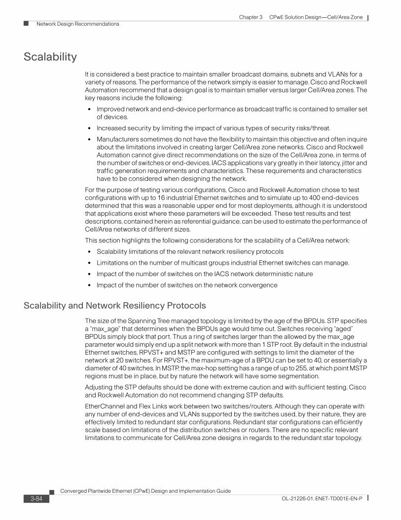
Chapter 3 CPwE Solution Design—Cell/Area Zone
Network Design Recommendations
Scalability
It is considered a best practice to maintain smaller broadcast domains, subnets and VLANs for a variety of reasons. The performance of the network simply is easier to manage. Cisco and Rockwell Automation recommend that a design goal is to maintain smaller versus larger Cell/Area zones. The key reasons include the following:
• Improved network and end-device performance as broadcast traffic is contained to smaller set of devices.
• Increased security by limiting the impact of various types of security risks/threat.
• Manufacturers sometimes do not have the flexibility to maintain this objective and often inquire about the limitations involved in creating larger Cell/Area zone networks. Cisco and Rockwell Automation cannot give direct recommendations on the size of the Cell/Area zone, in terms of the number of switches or end-devices. IACS applications vary greatly in their latency, jitter and traffic generation requirements and characteristics. These requirements and characteristics have to be considered when designing the network.
For the purpose of testing various configurations, Cisco and Rockwell Automation chose to test configurations with up to 16 industrial Ethernet switches and to simulate up to 400 end-devices determined that this was a reasonable upper end for most deployments, although it is understood that applications exist where these parameters will be exceeded. These test results and test descriptions, contained herein as referential guidance, can be used to estimate the performance of Cell/Area networks of different sizes.
This section highlights the following considerations for the scalability of a Cell/Area network:
• Scalability limitations of the relevant network resiliency protocols
• Limitations on the number of multicast groups industrial Ethernet switches can manage.
• Impact of the number of switches on the IACS network deterministic nature
• Impact of the number of switches on the network convergence
Scalability and Network Resiliency Protocols
The size of the Spanning Tree managed topology is limited by the age of the BPDUs. STP specifies a “max_age” that determines when the BPDUs age would time out. Switches receiving “aged” BPDUs simply block that port. Thus a ring of switches larger than the allowed by the max_age parameter would simply end up a split network with more than 1 STP root. By default in the industrial Ethernet switches, RPVST+ and MSTP are configured with settings to limit the diameter of the network at 20 switches. For RPVST+, the maximum-age of a BPDU can be set to 40, or essentially a diameter of 40 switches. In MSTP, the max-hop setting has a range of up to 255, at which point MSTP regions must be in place, but by nature the network will have some segmentation.
Adjusting the STP defaults should be done with extreme caution and with sufficient testing. Cisco and Rockwell Automation do not recommend changing STP defaults.
EtherChannel and Flex Links work between two switches/routers. Although they can operate with any number of end-devices and VLANs supported by the switches used, by their nature, they are effectively limited to redundant star configurations. Redundant star configurations can efficiently scale based on limitations of the distribution switches or routers. There are no specific relevant limitations to communicate for Cell/Area zone designs in regards to the redundant star topology.
3-84Converged Plantwide Ethernet (CPwE) Design and Implementation Guide
OL-21226-01, ENET-TD001E-EN-P
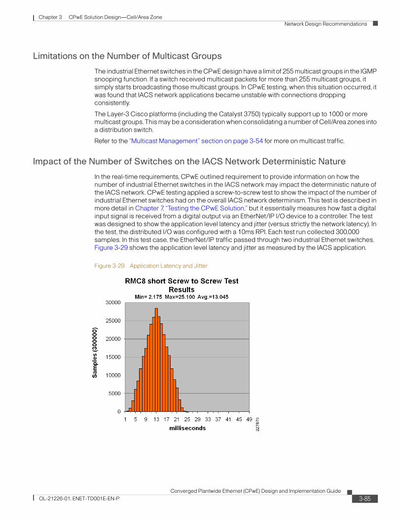
Chapter 3 CPwE Solution Design—Cell/Area Zone
Network Design Recommendations
Limitations on the Number of Multicast Groups
The industrial Ethernet switches in the CPwE design have a limit of 255 multicast groups in the IGMP snooping function. If a switch received multicast packets for more than 255 multicast groups, it simply starts broadcasting those multicast groups. In CPwE testing, when this situation occurred, it was found that IACS network applications became unstable with connections dropping consistently.
The Layer-3 Cisco platforms (including the Catalyst 3750) typically support up to 1000 or more multicast groups. This may be a consideration when consolidating a number of Cell/Area zones into a distribution switch.
Refer to the “Multicast Management” section on page 3-54 for more on multicast traffic.
Impact of the Number of Switches on the IACS Network Deterministic Nature
In the real-time requirements, CPwE outlined requirement to provide information on how the number of industrial Ethernet switches in the IACS network may impact the deterministic nature of the IACS network. CPwE testing applied a screw-to-screw test to show the impact of the number of industrial Ethernet switches had on the overall IACS network determinism. This test is described in more detail in Chapter 7, “Testing the CPwE Solution,” but it essentially measures how fast a digital input signal is received from a digital output via an EtherNet/IP I/O device to a controller. The test was designed to show the application level latency and jitter (versus strictly the network latency). In the test, the distributed I/O was configured with a 10ms RPI. Each test run collected 300,000 samples. In this test case, the EtherNet/IP traffic passed through two industrial Ethernet switches. Figure 3-29 shows the application level latency and jitter as measured by the IACS application.
Figure 3-29 Application Latency and Jitter
3-85Converged Plantwide Ethernet (CPwE) Design and Implementation Guide
OL-21226-01, ENET-TD001E-EN-P
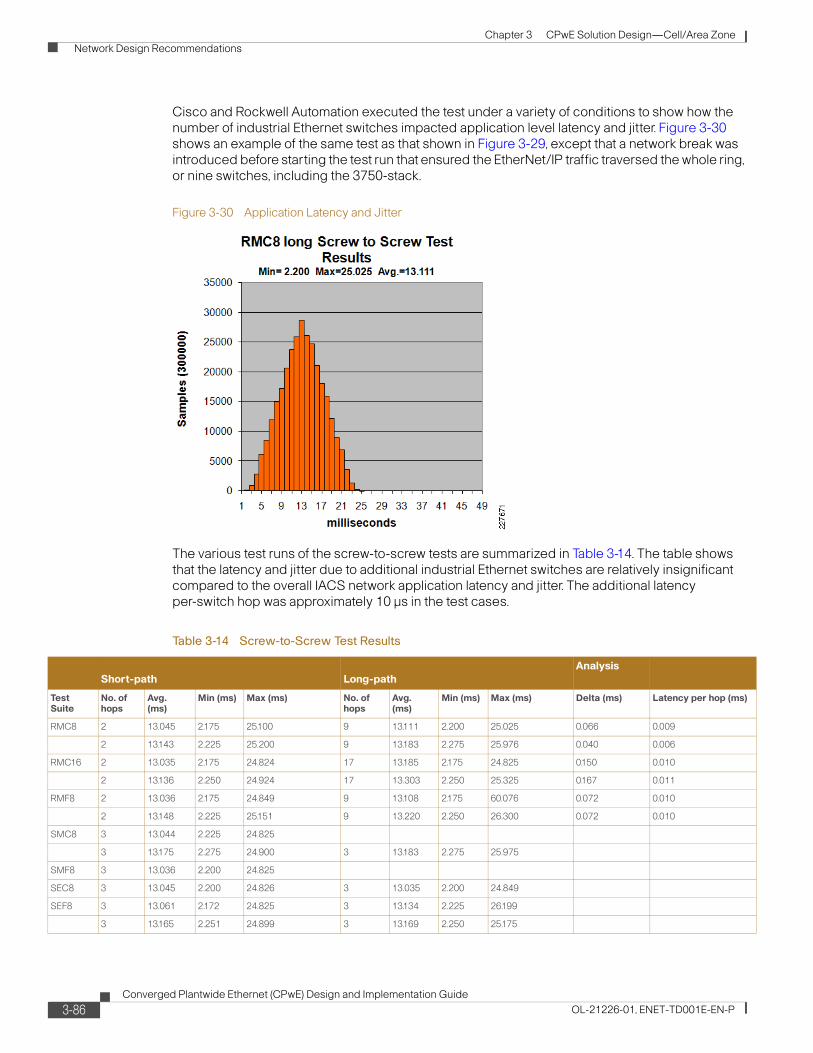
Chapter 3 CPwE Solution Design—Cell/Area Zone
Network Design Recommendations
Cisco and Rockwell Automation executed the test under a variety of conditions to show how the number of industrial Ethernet switches impacted application level latency and jitter. Figure 3-30 shows an example of the same test as that shown in Figure 3-29, except that a network break was introduced before starting the test run that ensured the EtherNet/IP traffic traversed the whole ring, or nine switches, including the 3750-stack.
Figure 3-30 Application Latency and Jitter
The various test runs of the screw-to-screw tests are summarized in Table 3-14. The table shows that the latency and jitter due to additional industrial Ethernet switches are relatively insignificant compared to the overall IACS network application latency and jitter. The additional latency per-switch hop was approximately 10 μs in the test cases.
Table 3-14 Screw-to-Screw Test Results
Short-path Long-pathAnalysis
Test Suite
No. of hops
Avg. (ms)
Min (ms) Max (ms) No. of hops
Avg. (ms)
Min (ms) Max (ms) Delta (ms) Latency per hop (ms)
RMC8 2 13.045 2.175 25.100 9 13.111 2.200 25.025 0.066 0.009
2 13.143 2.225 25.200 9 13.183 2.275 25.976 0.040 0.006
RMC16 2 13.035 2.175 24.824 17 13.185 2.175 24.825 0.150 0.010
2 13.136 2.250 24.924 17 13.303 2.250 25.325 0.167 0.011
RMF8 2 13.036 2.175 24.849 9 13.108 2.175 60.076 0.072 0.010
2 13.148 2.225 25.151 9 13.220 2.250 26.300 0.072 0.010
SMC8 3 13.044 2.225 24.825
3 13.175 2.275 24.900 3 13.183 2.275 25.975
SMF8 3 13.036 2.200 24.825
SEC8 3 13.045 2.200 24.826 3 13.035 2.200 24.849
SEF8 3 13.061 2.172 24.825 3 13.134 2.225 26.199
3 13.165 2.251 24.899 3 13.169 2.250 25.175
3-86Converged Plantwide Ethernet (CPwE) Design and Implementation Guide
OL-21226-01, ENET-TD001E-EN-P
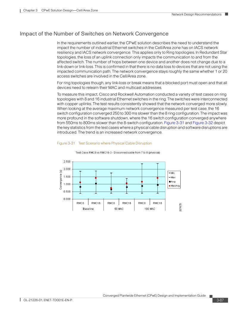
Chapter 3 CPwE Solution Design—Cell/Area Zone
Network Design Recommendations
Impact of the Number of Switches on Network Convergence
In the requirements outlined earlier, the CPwE solution describes the need to understand the impact the number of industrial Ethernet switches in the Cell/Area zone has on IACS network resiliency and IACS network convergence. This applies only to Ring topologies. In Redundant Star topologies, the loss of an uplink connection only impacts the communication to and from the affected switch. The number of hops between one device and another does not change due to a link-down or link-loss. This is confirmed in that there is no data loss to devices that are not using the impacted communication path. The network convergence stays roughly the same whether 1 or 20 access switches are involved in the Cell/Area zone.
For ring topologies though, any link-loss or break means that a blocked port must open and that all devices need to relearn their MAC and multicast addresses.
To measure this impact, Cisco and Rockwell Automation conducted a variety of test cases on ring topologies with 8 and 16 industrial Ethernet switches in the ring. The switches were interconnected with copper uplinks. The test results consistently showed that the network converged more slowly. When looking at the average maximum network convergence measured per test case, the 16 switch configuration converged 250 to 300 ms slower than the 8 ring configuration. The impact was more profound in the software shutdown, where the 16 switch configuration converged anywhere from 550ms to 800ms slower than the 8-switch configuration. Figure 3-31 and Figure 3-32 depict the key statistics from the test cases where a physical cable disruption and software disruptions are introduced. The trend is an increased network convergence.
Figure 3-31 Test Scenario where Physical Cable Disruption
3-87Converged Plantwide Ethernet (CPwE) Design and Implementation Guide
OL-21226-01, ENET-TD001E-EN-P
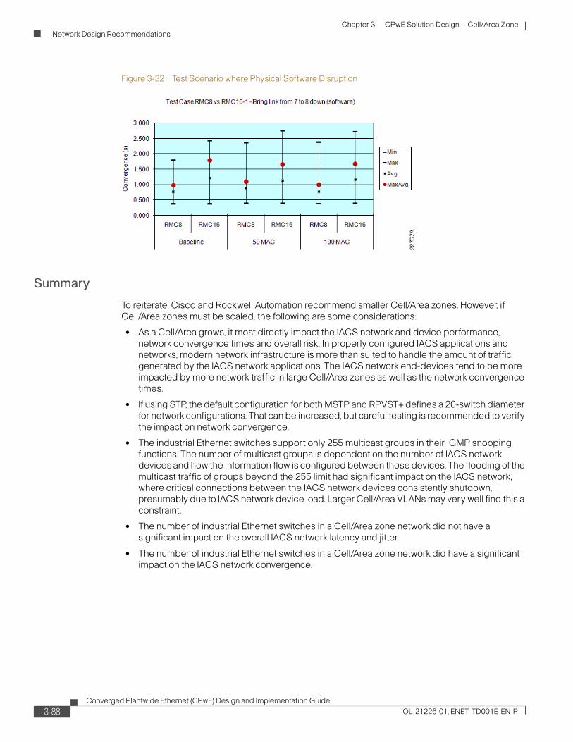
Chapter 3 CPwE Solution Design—Cell/Area Zone
Network Design Recommendations
Figure 3-32 Test Scenario where Physical Software Disruption
Summary
To reiterate, Cisco and Rockwell Automation recommend smaller Cell/Area zones. However, if Cell/Area zones must be scaled, the following are some considerations:
• As a Cell/Area grows, it most directly impact the IACS network and device performance, network convergence times and overall risk. In properly configured IACS applications and networks, modern network infrastructure is more than suited to handle the amount of traffic generated by the IACS network applications. The IACS network end-devices tend to be more impacted by more network traffic in large Cell/Area zones as well as the network convergence times.
• If using STP, the default configuration for both MSTP and RPVST+ defines a 20-switch diameter for network configurations. That can be increased, but careful testing is recommended to verify the impact on network convergence.
• The industrial Ethernet switches support only 255 multicast groups in their IGMP snooping functions. The number of multicast groups is dependent on the number of IACS network devices and how the information flow is configured between those devices. The flooding of the multicast traffic of groups beyond the 255 limit had significant impact on the IACS network, where critical connections between the IACS network devices consistently shutdown, presumably due to IACS network device load. Larger Cell/Area VLANs may very well find this a constraint.
• The number of industrial Ethernet switches in a Cell/Area zone network did not have a significant impact on the overall IACS network latency and jitter.
• The number of industrial Ethernet switches in a Cell/Area zone network did have a significant impact on the IACS network convergence.
3-88Converged Plantwide Ethernet (CPwE) Design and Implementation Guide
OL-21226-01, ENET-TD001E-EN-P


