
Page 1 1 of 20, EGU General Assembly, Apr 21, 2009
Vijay Natraj (Caltech), Hartmut Bösch (University of Leicester), Rob Spurr (RT
Solutions), Yuk Yung (Caltech)
EGU General Assembly, Vienna, AustriaEGU General Assembly, Vienna, Austria
April 21, 2009April 21, 2009
Simulations of Space-Based Near IR CO2 Observations over Ground Target

Page 2 2 of 20, EGU General Assembly, Apr 21, 2009
Outline
• CO2 from space
• Introduction to target mode
• 2OS polarization model
• Scenarios
• XCO2 Errors
• Conclusions
Page 3 3 of 20, EGU General Assembly, Apr 21, 2009
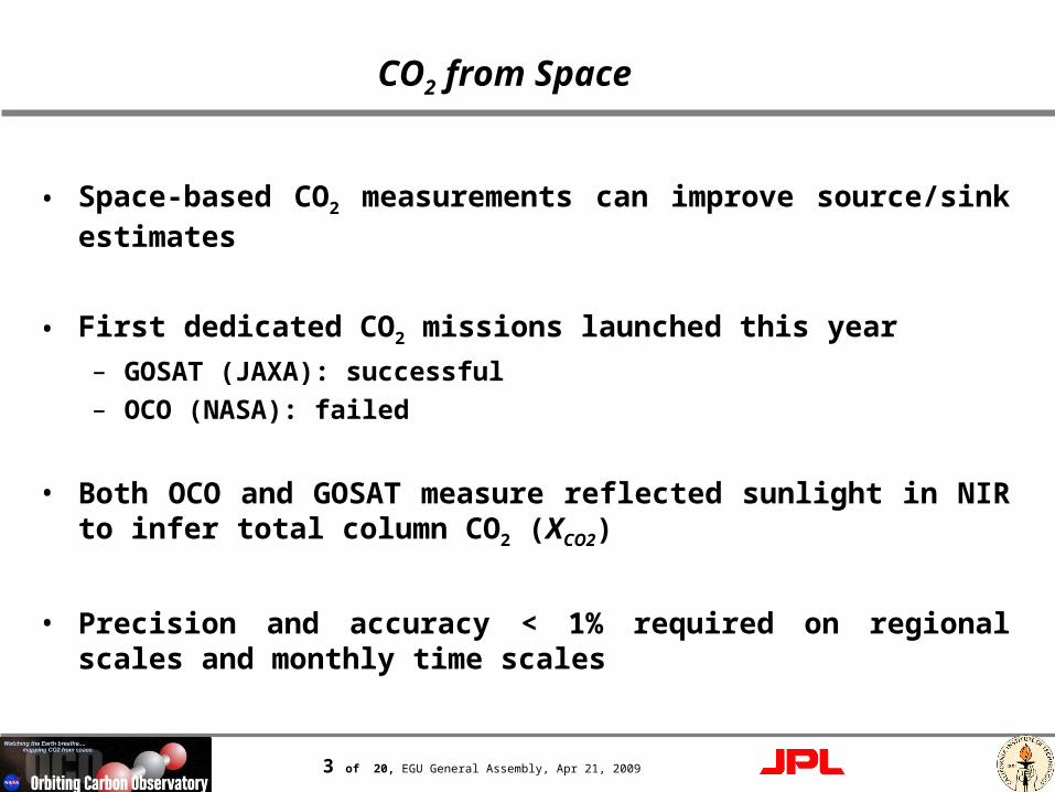
CO2 from Space
• Space-based CO2 measurements can improve source/sink estimates
• First dedicated CO2 missions launched this year
– GOSAT (JAXA): successful
– OCO (NASA): failed
• Both OCO and GOSAT measure reflected sunlight in NIR to infer total column CO2 (XCO2)
• Precision and accuracy < 1% required on regional scales and monthly time scales

Page 4 4 of 20, EGU General Assembly, Apr 21, 2009
Target Mode: Validation Tool
Spacecraft Coordinates
447-
m W
LE
F T
ow
er
Page 5 5 of 20, EGU General Assembly, Apr 21, 2009
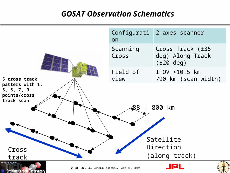
GOSAT Observation Schematics
88 – 800 km
Satellite Direction(along track)Cross track
Configuration 2-axes scanner
Scanning Cross
Cross Track (±35 deg) Along Track (±20 deg)
Field of view IFOV <10.5 km 790 km (scan width)
5 cross track patters with 1, 3, 5, 7, 9 points/cross track scan

Page 6 6 of 20, EGU General Assembly, Apr 21, 2009
Importance of Polarization
• Polarization is a result of scattering
• The Earth’s atmosphere contains molecules, aerosols and clouds, all of which contribute to scattering
• Surfaces can also polarize, in some cases significantly (e.g., ocean)
• Satellite instruments could be polarization sensitive
• Polarization depends on solar and viewing angles and will therefore introduce spatial biases in XCO2 if not accounted for

Page 7 7 of 20, EGU General Assembly, Apr 21, 2009
Polarization Characteristics of Different Viewing Modes
• Light with polarization parallel to slit (OCO-like instrument)
• I: intensity; Q, U: components of linear polarization; : angle between slit axis and principal plane
• Nadir and glint modes:
• Target mode: measurement not restricted to principal plane
UQII 2sin2cos2
1//
o90

Page 8 8 of 20, EGU General Assembly, Apr 21, 2009
2OS Model Schematic
Scenario 1 Scenario 2
scatterer
Scenario 3
scatterer
Scenario 4
scatterer 1
scatterer 2
Natraj and Spurr, JQSRT, 107, 263–293, 2007

Page 9 9 of 20, EGU General Assembly, Apr 21, 2009
Scenarios
• Location: Bremen (validation site for space-based CO2 measurements)
• Solar Zenith Angle (SZA): 50.4°
• Scattering Angle: 85°–150°
• Scatterer scenarios– Aerosol only: (OD) 0.05, 0.3, 0.3 (high)– Cirrus only: (OD) 0.05, 0.3, 0.3 (low)– Aerosol and cirrus:
• AOD - 0.05, COD - 0.25 (at 750 nm)• AOD - 0.25, COD - 0.05 (at 750 nm)
• Surface: Lambertian

Page 10 10 of 20, EGU General Assembly, Apr 21, 2009
Sample Radiance Spectrum
O2 A band
Weak CO2 band
Strong CO2 band

Page 11 11 of 20, EGU General Assembly, Apr 21, 2009
XCO2 Errors: Example

Page 12 12 of 20, EGU General Assembly, Apr 21, 2009
XCO2 Errors: Example
Two orders of magnitude worse results for scalar model

Page 13 13 of 20, EGU General Assembly, Apr 21, 2009
XCO2 Errors: Summary
• Scalar– High altitude scattering always gives large errors
• Underestimation of photon path length
• Highly polarized single scattering from higher altitudes
– For similar scattering altitudes, higher scattering OD better
• Multiple scattering depolarizes
• 2OS– Thin cirrus modeled well
– Largest errors for large amounts of high altitude scattering
• Polarized multiple scattering from higher altitudes
• Aerosol and cirrus have opposite polarization• Different spectral extinction and scattering behavior for aerosol
and cirrus

Page 14 14 of 20, EGU General Assembly, Apr 21, 2009
XCO2 Precision

Page 15 15 of 20, EGU General Assembly, Apr 21, 2009
Averaging Kernels
Page 16 16 of 20, EGU General Assembly, Apr 21, 2009
Summary
• Target mode is important for validating space-based XCO2 retrievals (such as those from GOSAT)
• Ignoring polarization could lead to significant errors in retrieved XCO2
• 2OS approach to account for polarization works very well
• Careful scene and geometry selection necessary to do proper validation
• 2OS model can be applied directly to GOSAT data to take advantage of polarization measurements

Page 17 17 of 20, EGU General Assembly, Apr 21, 2009
Backup SlidesBackup Slides

Page 18 18 of 20, EGU General Assembly, Apr 21, 2009
RT Model
• Multiple scattering model: LIDORT (L) – scalar; VLIDORT (VL) - vector– Discrete ordinate solution for Stokes vector
– Linearized: derivatives of intensity w.r.t. optical depth and single scattering albedo obtained analytically
• Polarization: 2 Orders of Scattering (2OS)– Polarization approximated by two orders of scattering
– Analytic integration over optical depth
– Fast invariant imbedding approach to add individual layers
– Linearized

Page 19 19 of 20, EGU General Assembly, Apr 21, 2009
Linear Error Analysis
• Forward model errors systematic
• Bias in retrieved parameters x
• Bias can be expressed as follows:
• G: gain matrix– Describes mapping of measurement variations into retrieved vector
variations
• ΔF: forward model error
FGx

Page 20 20 of 20, EGU General Assembly, Apr 21, 2009
Degrees of Freedom


