10. PALLETIZING FUNCTION B-82594EN-2/01
- 690 -
10 PALLETIZING FUNCTION This chapter explains the palletizing function. Contents of this chapter
10.1 PALLETIZING FUNCTION ...................................................691 10.2 PALLETIZING INSTRUCTIONS...........................................694 10.3 TEACHING THE PALLETIZING FUNCTION .....................696 10.4 EXECUTING THE PALLETIZING FUNCTION...................721 10.5 MODIFYING THE PALLETIZING FUNCTION...................725 10.6 PALLETIZING FUNCTION WITH EXTENDED AXES ......727 10.7 PALLETIZING ALL-POINT TEACHING .............................728
B-82594EN-2/01 10. PALLETIZING FUNCTION
- 691 -
10.1 PALLETIZING FUNCTION
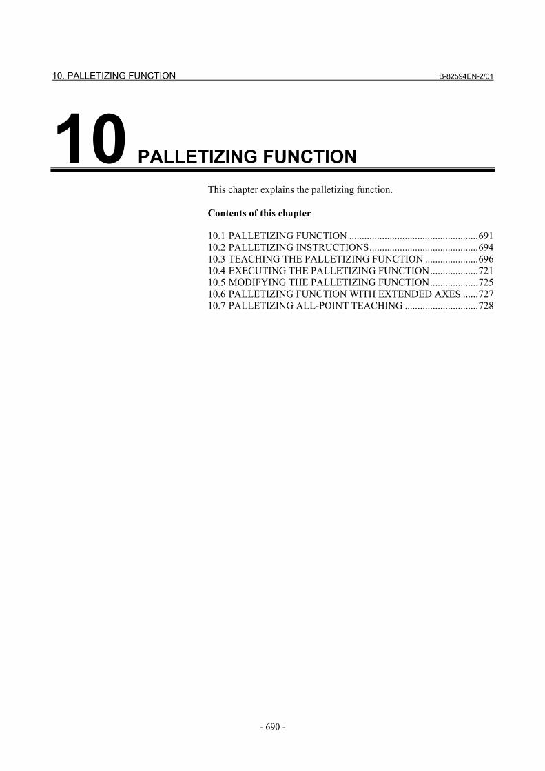
Palletizing function Palletizing is a function for the orderly stacking of workpieces by only teaching several representative points. • A stacking pattern can be created easily by teaching representative
stack points. • A path pattern can be created by teaching path points (approach
points and retraction points). • Multiple path patterns can be set to perform palletizing in a wide
variety of patterns.
Fig. 10.1 (a) Palletizing
Structure of the palletizing function
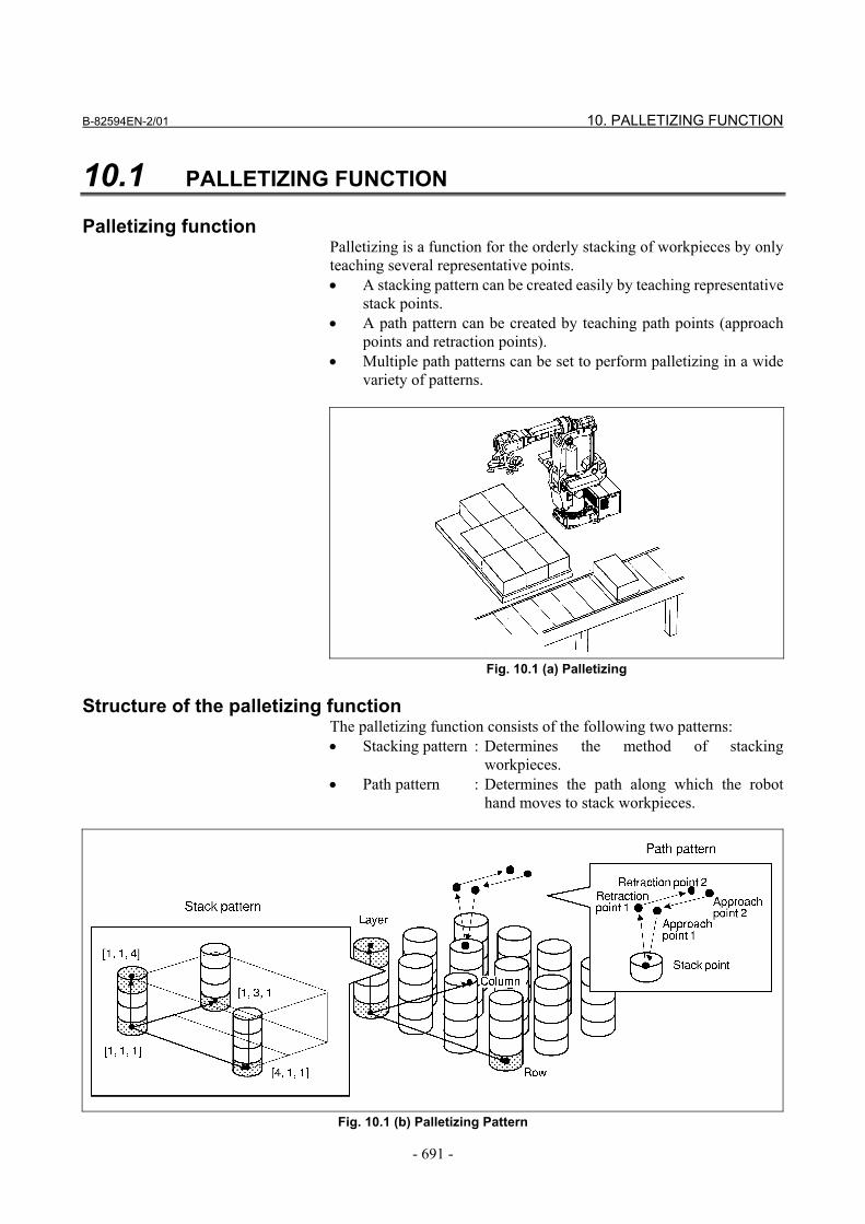
The palletizing function consists of the following two patterns: • Stacking pattern : Determines the method of stacking
workpieces. • Path pattern : Determines the path along which the robot
hand moves to stack workpieces.
Fig. 10.1 (b) Palletizing Pattern
10. PALLETIZING FUNCTION B-82594EN-2/01
- 692 -
Types of palletizing
There are the following four types of palletizing according to the methods for setting stack and path patterns (See Section 10.3). • Palletizing B and palletizing BX • Palletizing E and palletizing EX
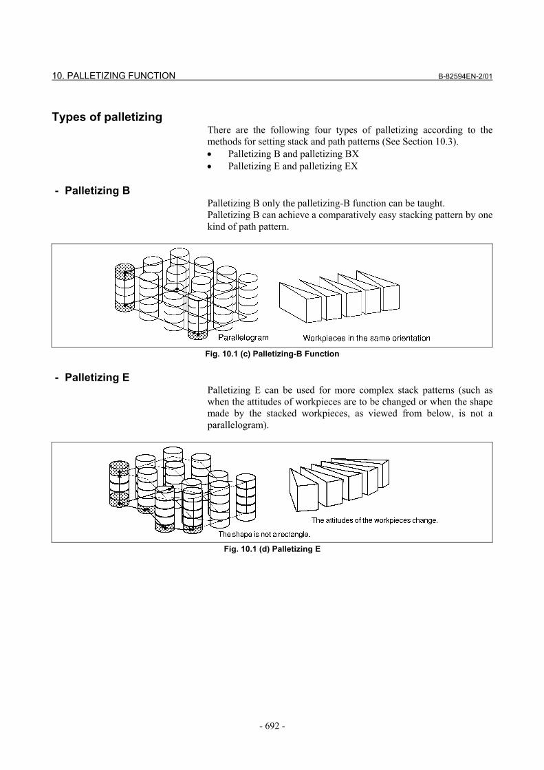
- Palletizing B Palletizing B only the palletizing-B function can be taught. Palletizing B can achieve a comparatively easy stacking pattern by one kind of path pattern.
Fig. 10.1 (c) Palletizing-B Function
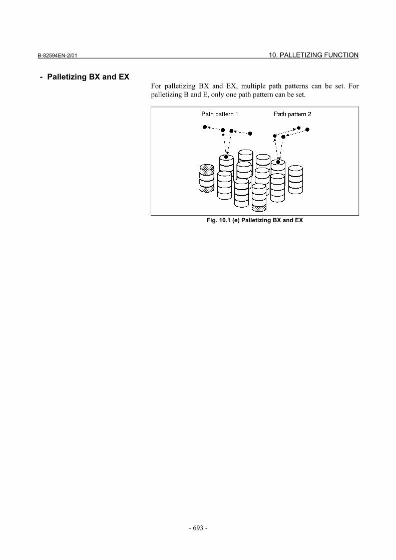
- Palletizing E Palletizing E can be used for more complex stack patterns (such as when the attitudes of workpieces are to be changed or when the shape made by the stacked workpieces, as viewed from below, is not a parallelogram).
Fig. 10.1 (d) Palletizing E
B-82594EN-2/01 10. PALLETIZING FUNCTION
- 693 -
- Palletizing BX and EX For palletizing BX and EX, multiple path patterns can be set. For palletizing B and E, only one path pattern can be set.
Fig. 10.1 (e) Palletizing BX and EX
10. PALLETIZING FUNCTION B-82594EN-2/01
- 694 -
10.2 PALLETIZING INSTRUCTIONS The following palletizing instructions are available:
Table 10.2 Palletizing instructions Instruction Function
Palletizing instruction
Calculates the current path based on a stacking pattern, path pattern, and the value held in the palletizing register, and rewrites the position data of a palletizing motion instruction.
Palletizing motion instruction
A motion instruction dedicated to palletizing. It has position data of an approach point, stack point, or retraction point.
Palletizing end instruction
Increments (or decrements) the value of a palletizing register.
Palletizing instruction
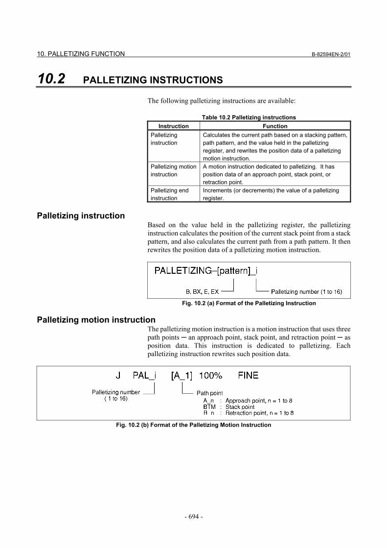
Based on the value held in the palletizing register, the palletizing instruction calculates the position of the current stack point from a stack pattern, and also calculates the current path from a path pattern. It then rewrites the position data of a palletizing motion instruction.
Fig. 10.2 (a) Format of the Palletizing Instruction
Palletizing motion instruction The palletizing motion instruction is a motion instruction that uses three path points ─ an approach point, stack point, and retraction point ─ as position data. This instruction is dedicated to palletizing. Each palletizing instruction rewrites such position data.
Fig. 10.2 (b) Format of the Palletizing Motion Instruction
B-82594EN-2/01 10. PALLETIZING FUNCTION
- 695 -
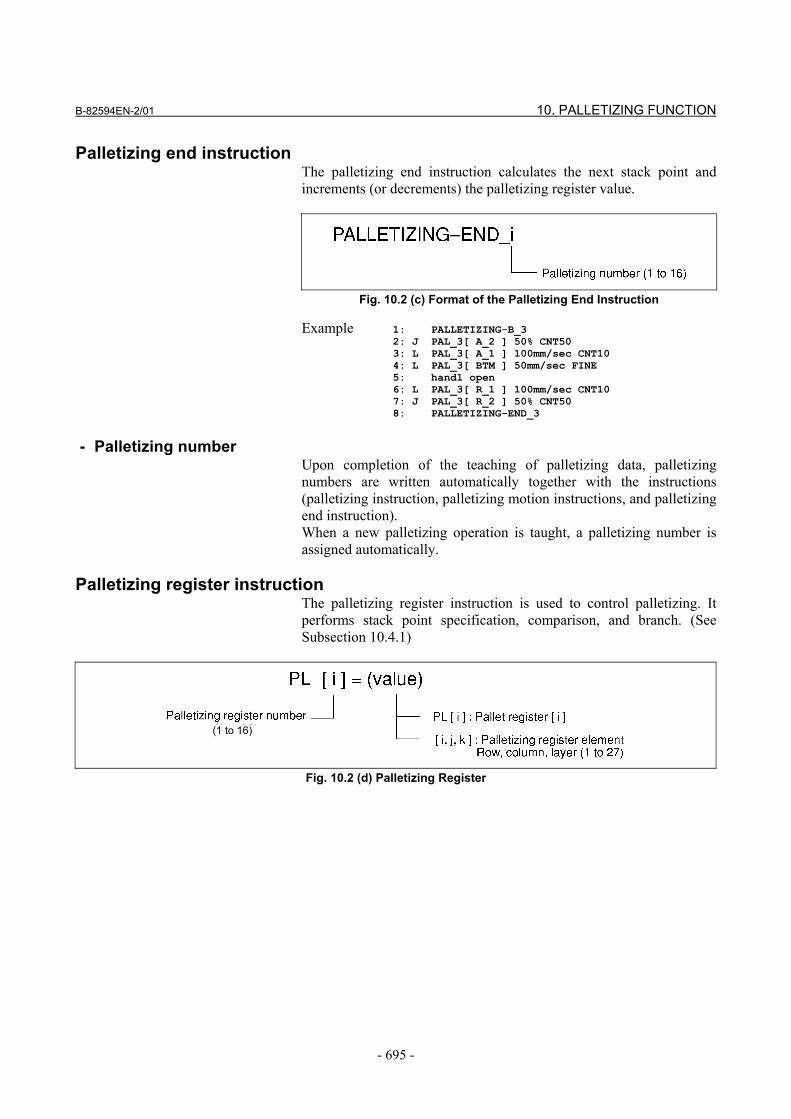
Palletizing end instruction The palletizing end instruction calculates the next stack point and increments (or decrements) the palletizing register value.
Fig. 10.2 (c) Format of the Palletizing End Instruction
Example 1: PALLETIZING-B_3 2: J PAL_3[ A_2 ] 50% CNT50 3: L PAL_3[ A_1 ] 100mm/sec CNT10 4: L PAL_3[ BTM ] 50mm/sec FINE 5: hand1 open 6: L PAL_3[ R_1 ] 100mm/sec CNT10 7: J PAL_3[ R_2 ] 50% CNT50 8: PALLETIZING-END_3
- Palletizing number
Upon completion of the teaching of palletizing data, palletizing numbers are written automatically together with the instructions (palletizing instruction, palletizing motion instructions, and palletizing end instruction). When a new palletizing operation is taught, a palletizing number is assigned automatically.
Palletizing register instruction The palletizing register instruction is used to control palletizing. It performs stack point specification, comparison, and branch. (See Subsection 10.4.1)
(1 to 16)
Fig. 10.2 (d) Palletizing Register
10. PALLETIZING FUNCTION B-82594EN-2/01
- 696 -
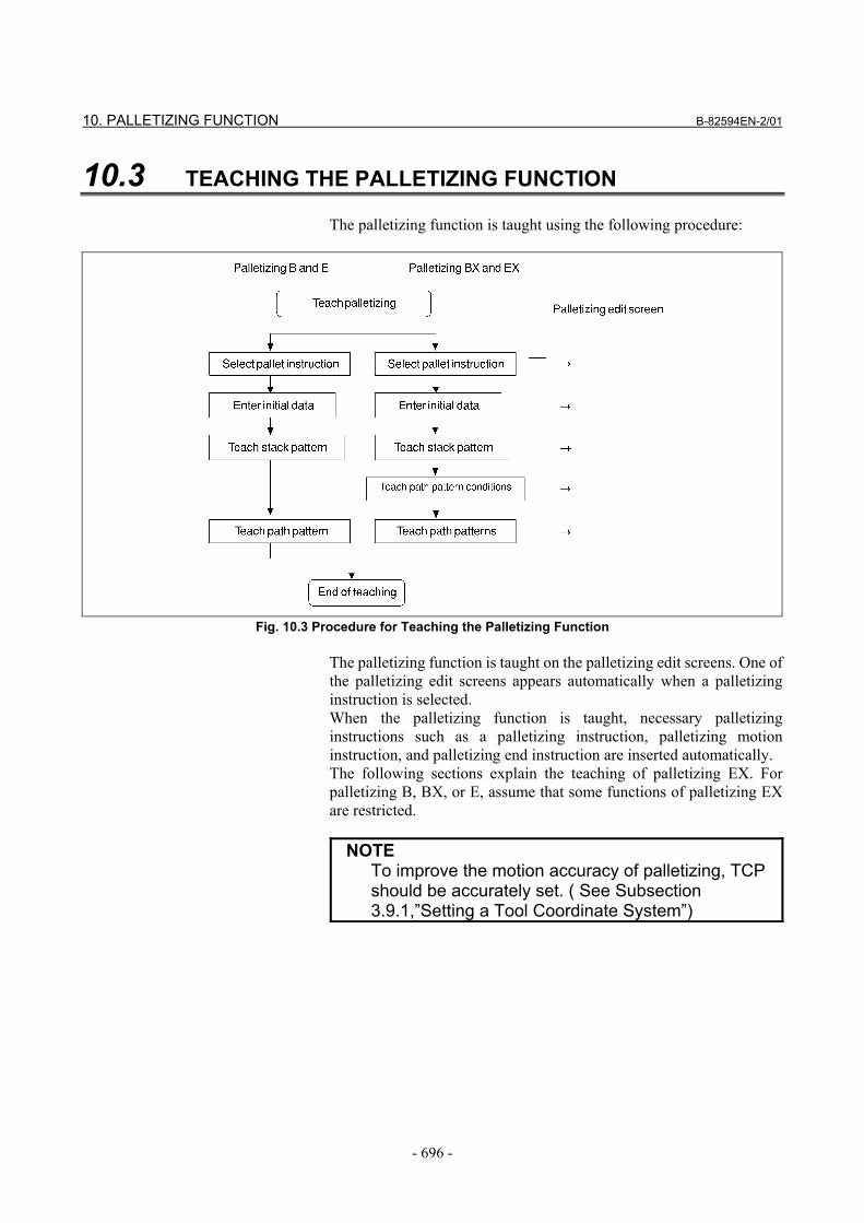
10.3 TEACHING THE PALLETIZING FUNCTION The palletizing function is taught using the following procedure:
Fig. 10.3 Procedure for Teaching the Palletizing Function
The palletizing function is taught on the palletizing edit screens. One of the palletizing edit screens appears automatically when a palletizing instruction is selected. When the palletizing function is taught, necessary palletizing instructions such as a palletizing instruction, palletizing motion instruction, and palletizing end instruction are inserted automatically. The following sections explain the teaching of palletizing EX. For palletizing B, BX, or E, assume that some functions of palletizing EX are restricted.
NOTE To improve the motion accuracy of palletizing, TCP
should be accurately set. ( See Subsection 3.9.1,”Setting a Tool Coordinate System”)
B-82594EN-2/01 10. PALLETIZING FUNCTION
- 697 -
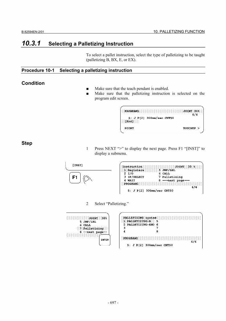
10.3.1 Selecting a Palletizing Instruction To select a pallet instruction, select the type of palletizing to be taught (palletizing B, BX, E, or EX).
Procedure 10-1 Selecting a palletizing instruction
Condition ■ Make sure that the teach pendant is enabled. ■ Make sure that the palletizing instruction is selected on the
program edit screen.
Step 1 Press NEXT “>” to display the next page. Press F1 “[INST]” to
display a submenu.
2 Select “Palletizing.”
10. PALLETIZING FUNCTION B-82594EN-2/01
- 698 -
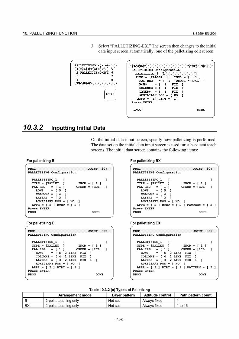
3 Select “PALLETIZING-EX.” The screen then changes to the initial data input screen automatically, one of the palletizing edit screen.
10.3.2 Inputting Initial Data On the initial data input screen, specify how palletizing is performed. The data set on the initial data input screen is used for subsequent teach screens. The initial data screen contains the following items:
Table 10.3.2 (a) Types of Palletizing Arrangement mode Layer pattern Attitude control Path pattern count
B 2-point teaching only Not set Always fixed 1 BX 2-point teaching only Not set Always fixed 1 to 16
B-82594EN-2/01 10. PALLETIZING FUNCTION
- 699 -
Arrangement mode Layer pattern Attitude control Path pattern count E 2-point teaching, all-point teaching,
or interval specification Set Fixed or split 1
EX 2-point teaching, all-point teaching, or interval specification
Set Fixed or split 1 to 16
When a pallet instruction is selected, the initial data input screen corresponding to the selected type of palletizing appears. For palletizing EX, all palletizing functions can be specified. For palletizing B, BX, and E, restrictions are imposed on the specification of the functions. This section explains how to enter initial data for palletizing EX. For palletizing B, BX, or E, assume that some functions of palletizing EX are restricted.
Table 10.3.2 (b) Initial Palletizing Data Palletizing number A number is assigned automatically when a palletizing statement is taught.
PALLETIZING_N: 1 to 16 Palletizing type Specify whether the palletizing register is to be incremented or decremented by the palletizing
end instruction. (See Subsection 10.4.1.) Select stacking (PALLET) or unstacking (DEPALLET).
Register increment Specify the value by which the value held in the palletizing register is to be incremented or decremented by the palletizing end instruction. (See Subsection 10.4.1.)
Palletizing register Specify the palletizing register to be used by the palletizing instruction and palletizing end instruction.
Order Specify the stacking (unstacking) order of row, column, and layer. R: Row, C: Column, L: Layer
Numbers of rows, columns, and layers Arrangement mode Attitude control Layer pattern count
Numbers of rows, columns, and layers for a stacking pattern. (See Subsection 10.3.3.) 1 to 127 How rows, columns, and layers are arranged for a stack pattern. The 2-point or all-point teaching, or interval specification can be specified (only for palletizing E or EX). Control the attitude at rows, columns, and layers for a stacking pattern. Select E or EX. How workpieces are stacked can be specified for each layer (only for palletizing E or EX). 1 to 16
Number of approach points Number of retraction points Path pattern count
Number of approach points in a path pattern. (See Subsection 10.3.5.) 0 to 7 Number of retraction points in a path pattern. (See Subsection 10.3.5.) 0 to 7 Number of path patterns (Subsection 10.3.4) (only for palletizing BX or EX). 1 to 16
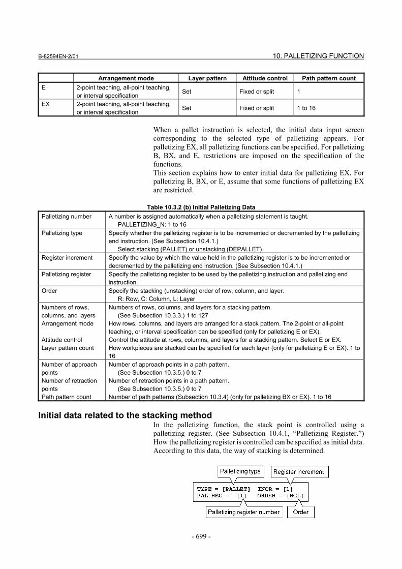
Initial data related to the stacking method
In the palletizing function, the stack point is controlled using a palletizing register. (See Subsection 10.4.1, “Palletizing Register.”) How the palletizing register is controlled can be specified as initial data. According to this data, the way of stacking is determined.
10. PALLETIZING FUNCTION B-82594EN-2/01
- 700 -
• For the pallet type (TYPE), specify either PALLET or
DEPALLET (standard setting: PALLET). (See Subsection 10.4.1, “Palletizing Register.”)
• For the register increment (INCR), specify by which amount the stack (unstack) position advances or retracts. That is, specify a value by which the palletizing register is incremented or decremented by the palletizing end instruction. The standard setting is 1. (See Subsection 10.4.1, “Palletizing Register.”)
• As the palletizing register, specify the register number of a palletizing register used for stack control.
CAUTION
Make sure that the specified palletizing register number is not used by another palletizing function.
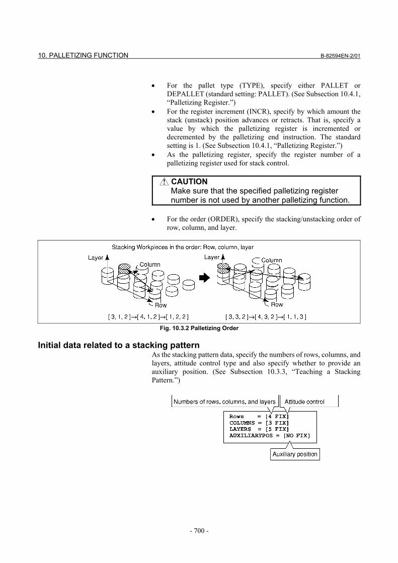
• For the order (ORDER), specify the stacking/unstacking order of
row, column, and layer.
Fig. 10.3.2 Palletizing Order
Initial data related to a stacking pattern
As the stacking pattern data, specify the numbers of rows, columns, and layers, attitude control type and also specify whether to provide an auxiliary position. (See Subsection 10.3.3, “Teaching a Stacking Pattern.”)
B-82594EN-2/01 10. PALLETIZING FUNCTION
- 701 -
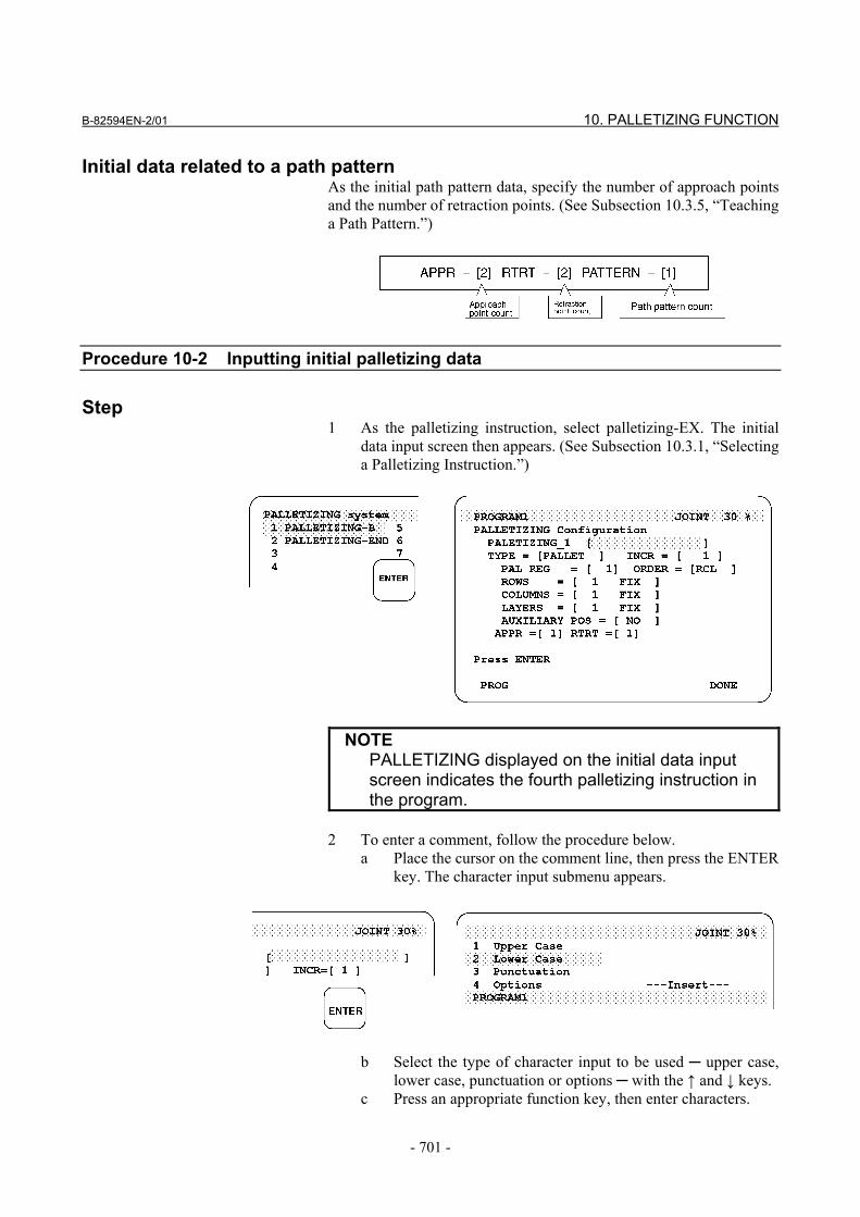
Initial data related to a path pattern As the initial path pattern data, specify the number of approach points and the number of retraction points. (See Subsection 10.3.5, “Teaching a Path Pattern.”)
Procedure 10-2 Inputting initial palletizing data
Step 1 As the palletizing instruction, select palletizing-EX. The initial
data input screen then appears. (See Subsection 10.3.1, “Selecting a Palletizing Instruction.”)
NOTE PALLETIZING displayed on the initial data input
screen indicates the fourth palletizing instruction in the program.
2 To enter a comment, follow the procedure below.
a Place the cursor on the comment line, then press the ENTER key. The character input submenu appears.
b Select the type of character input to be used ─ upper case, lower case, punctuation or options ─ with the ↑ and ↓ keys.
c Press an appropriate function key, then enter characters.
10. PALLETIZING FUNCTION B-82594EN-2/01
- 702 -
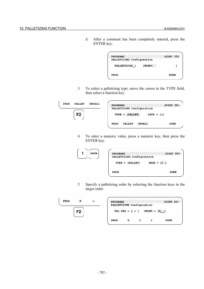
d After a comment has been completely entered, press the ENTER key.
3 To select a palletizing type, move the cursor to the TYPE field,
then select a function key.
4 To enter a numeric value, press a numeric key, then press the
ENTER key.
5 Specify a palletizing order by selecting the function keys in the
target order.
B-82594EN-2/01 10. PALLETIZING FUNCTION
- 703 -
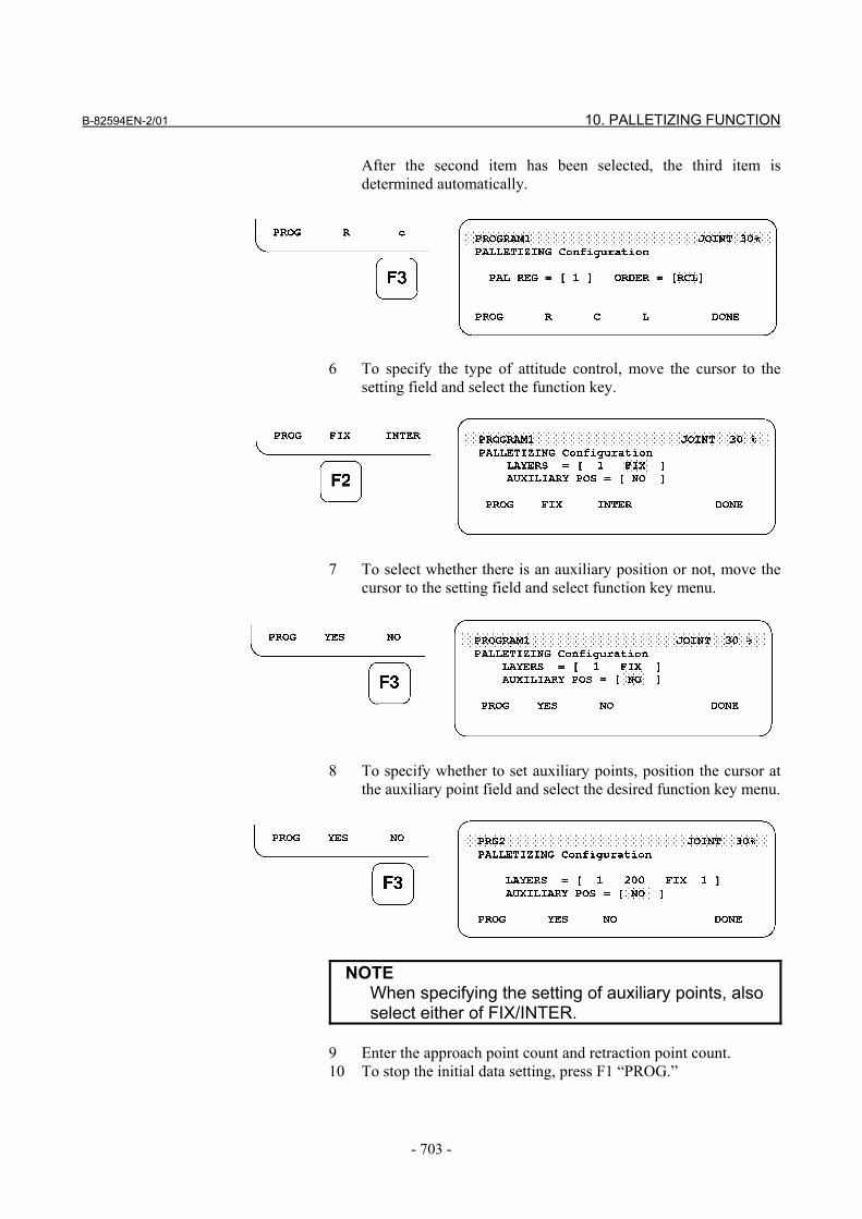
After the second item has been selected, the third item is determined automatically.
6 To specify the type of attitude control, move the cursor to the
setting field and select the function key.
7 To select whether there is an auxiliary position or not, move the
cursor to the setting field and select function key menu.
8 To specify whether to set auxiliary points, position the cursor at
the auxiliary point field and select the desired function key menu.
NOTE When specifying the setting of auxiliary points, also
select either of FIX/INTER. 9 Enter the approach point count and retraction point count. 10 To stop the initial data setting, press F1 “PROG.”
10. PALLETIZING FUNCTION B-82594EN-2/01
- 704 -
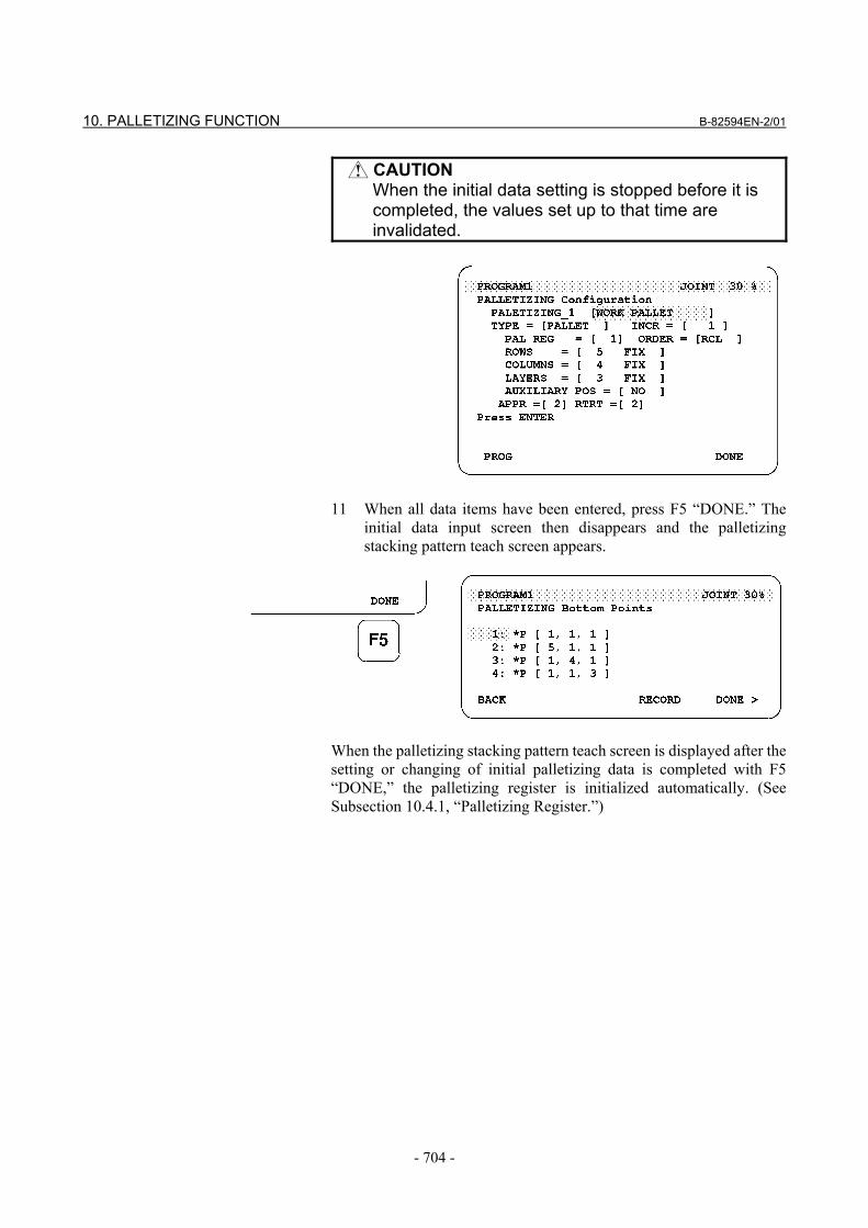
CAUTION When the initial data setting is stopped before it is
completed, the values set up to that time are invalidated.
11 When all data items have been entered, press F5 “DONE.” The
initial data input screen then disappears and the palletizing stacking pattern teach screen appears.
When the palletizing stacking pattern teach screen is displayed after the setting or changing of initial palletizing data is completed with F5 “DONE,” the palletizing register is initialized automatically. (See Subsection 10.4.1, “Palletizing Register.”)
B-82594EN-2/01 10. PALLETIZING FUNCTION
- 705 -
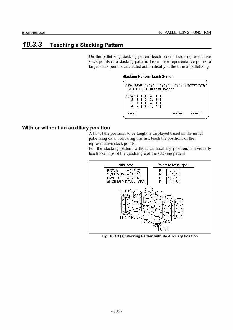
10.3.3 Teaching a Stacking Pattern On the palletizing stacking pattern teach screen, teach representative stack points of a stacking pattern. From these representative points, a target stack point is calculated automatically at the time of palletizing.
With or without an auxiliary position A list of the positions to be taught is displayed based on the initial palletizing data. Following this list, teach the positions of the representative stack points. For the stacking pattern without an auxiliary position, individually teach four tops of the quadrangle of the stacking pattern.
Fig. 10.3.3 (a) Stacking Pattern with No Auxiliary Position
10. PALLETIZING FUNCTION B-82594EN-2/01
- 706 -
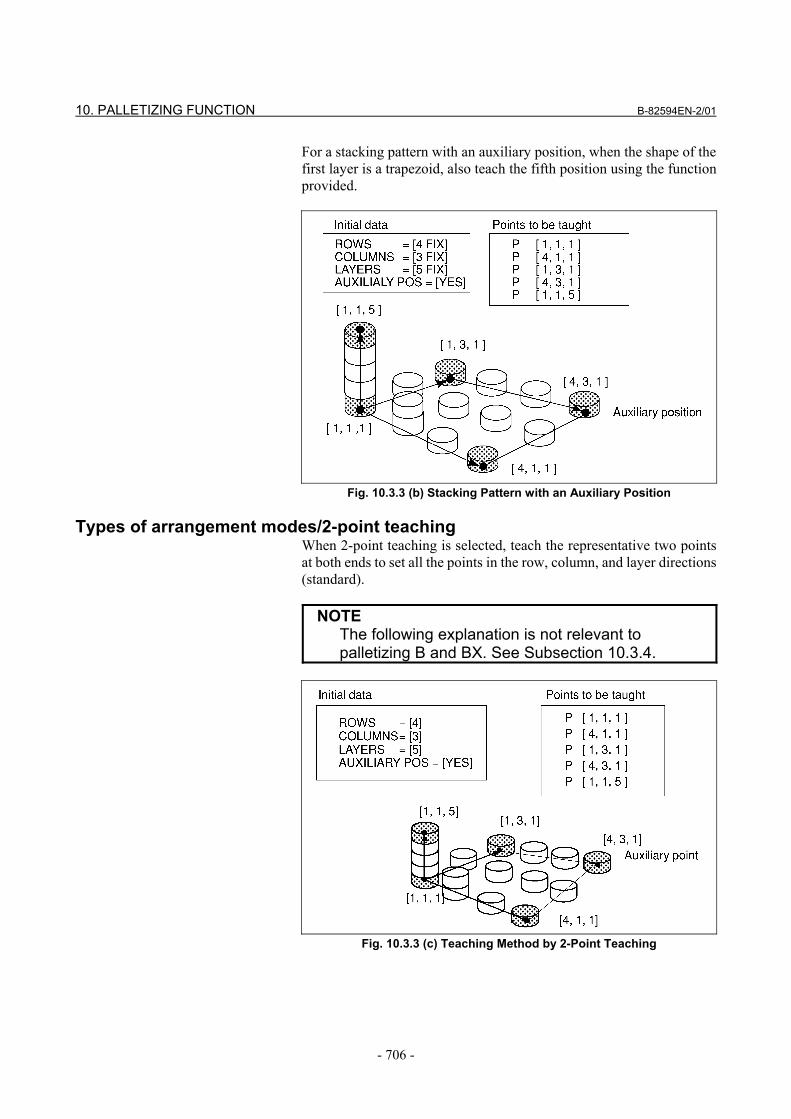
For a stacking pattern with an auxiliary position, when the shape of the first layer is a trapezoid, also teach the fifth position using the function provided.
Fig. 10.3.3 (b) Stacking Pattern with an Auxiliary Position
Types of arrangement modes/2-point teaching When 2-point teaching is selected, teach the representative two points at both ends to set all the points in the row, column, and layer directions (standard).
NOTE The following explanation is not relevant to
palletizing B and BX. See Subsection 10.3.4.
Fig. 10.3.3 (c) Teaching Method by 2-Point Teaching
B-82594EN-2/01 10. PALLETIZING FUNCTION
- 707 -
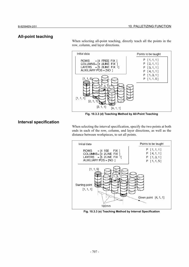
All-point teaching When selecting all-point teaching, directly teach all the points in the row, column, and layer directions.
Fig. 10.3.3 (d) Teaching Method by All-Point Teaching
Interval specification When selecting the interval specification, specify the two points at both ends in each of the row, column, and layer directions, as well as the distance between workpieces, to set all points.
Fig. 10.3.3 (e) Teaching Method by Interval Specification
10. PALLETIZING FUNCTION B-82594EN-2/01
- 708 -
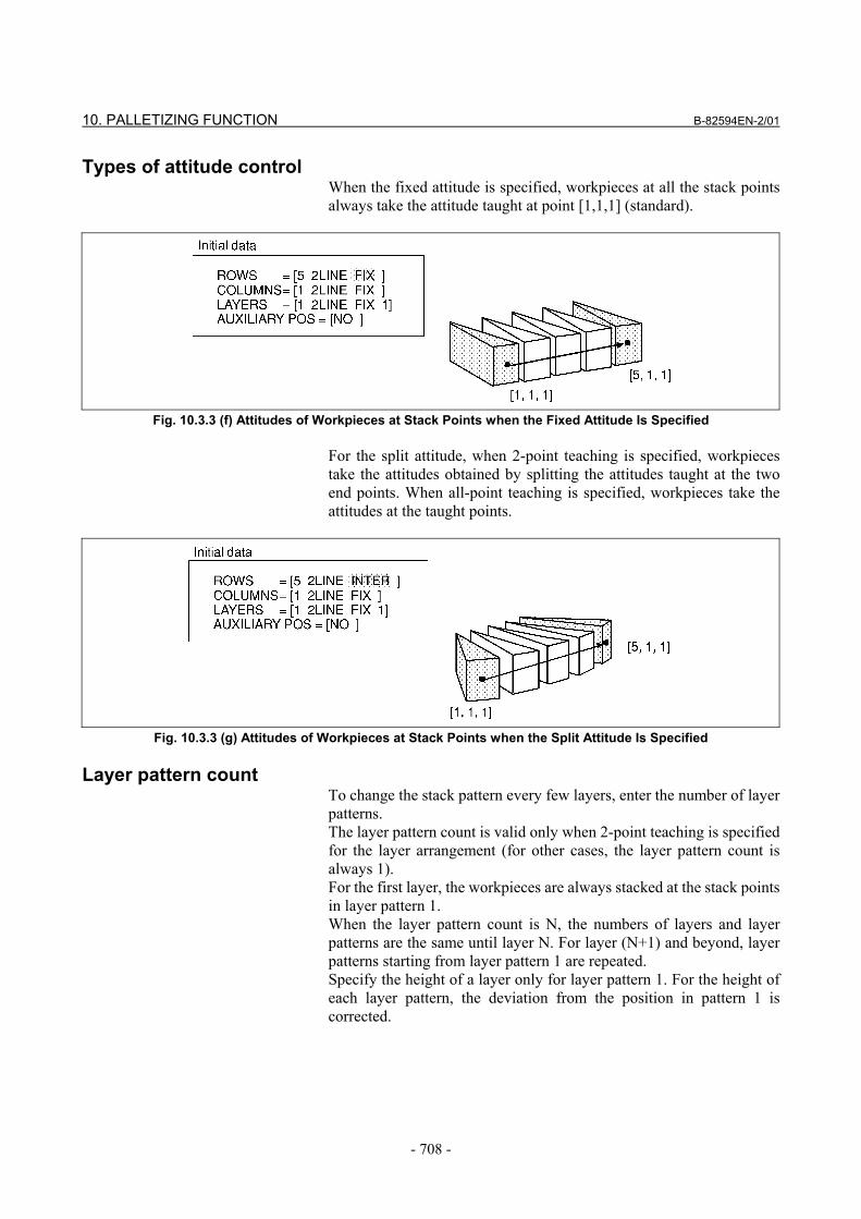
Types of attitude control When the fixed attitude is specified, workpieces at all the stack points always take the attitude taught at point [1,1,1] (standard).
Fig. 10.3.3 (f) Attitudes of Workpieces at Stack Points when the Fixed Attitude Is Specified
For the split attitude, when 2-point teaching is specified, workpieces take the attitudes obtained by splitting the attitudes taught at the two end points. When all-point teaching is specified, workpieces take the attitudes at the taught points.
Fig. 10.3.3 (g) Attitudes of Workpieces at Stack Points when the Split Attitude Is Specified
Layer pattern count
To change the stack pattern every few layers, enter the number of layer patterns. The layer pattern count is valid only when 2-point teaching is specified for the layer arrangement (for other cases, the layer pattern count is always 1). For the first layer, the workpieces are always stacked at the stack points in layer pattern 1. When the layer pattern count is N, the numbers of layers and layer patterns are the same until layer N. For layer (N+1) and beyond, layer patterns starting from layer pattern 1 are repeated. Specify the height of a layer only for layer pattern 1. For the height of each layer pattern, the deviation from the position in pattern 1 is corrected.
B-82594EN-2/01 10. PALLETIZING FUNCTION
- 709 -
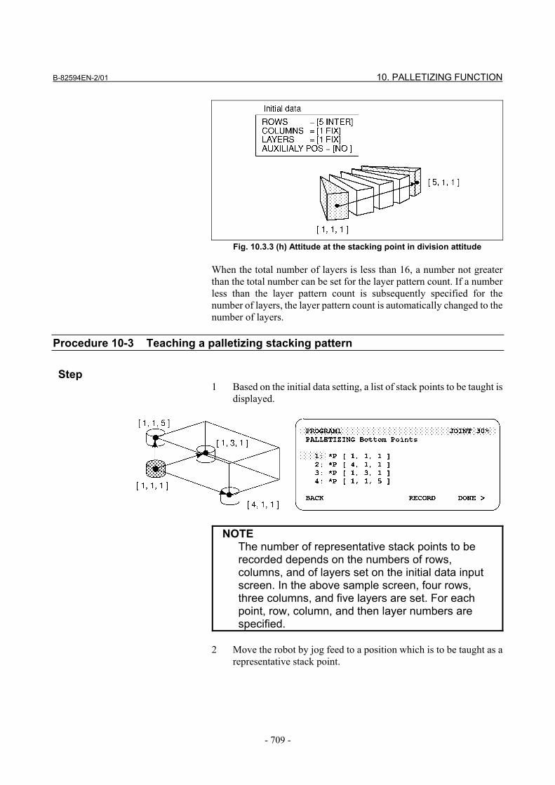
Fig. 10.3.3 (h) Attitude at the stacking point in division attitude
When the total number of layers is less than 16, a number not greater than the total number can be set for the layer pattern count. If a number less than the layer pattern count is subsequently specified for the number of layers, the layer pattern count is automatically changed to the number of layers.
Procedure 10-3 Teaching a palletizing stacking pattern
Step 1 Based on the initial data setting, a list of stack points to be taught is
displayed.
NOTE The number of representative stack points to be
recorded depends on the numbers of rows, columns, and of layers set on the initial data input screen. In the above sample screen, four rows, three columns, and five layers are set. For each point, row, column, and then layer numbers are specified.
2 Move the robot by jog feed to a position which is to be taught as a
representative stack point.
10. PALLETIZING FUNCTION B-82594EN-2/01
- 710 -
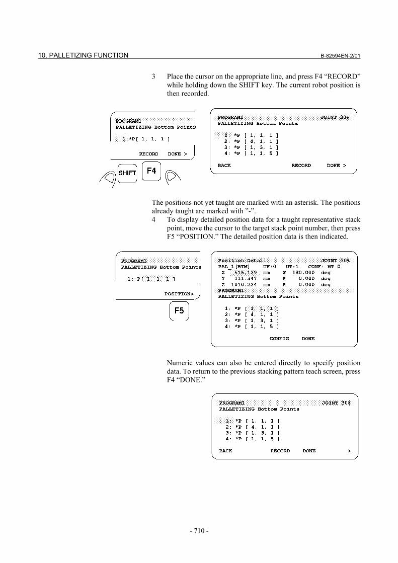
3 Place the cursor on the appropriate line, and press F4 “RECORD” while holding down the SHIFT key. The current robot position is then recorded.
The positions not yet taught are marked with an asterisk. The positions already taught are marked with ”-”. 4 To display detailed position data for a taught representative stack
point, move the cursor to the target stack point number, then press F5 “POSITION.” The detailed position data is then indicated.
Numeric values can also be entered directly to specify position
data. To return to the previous stacking pattern teach screen, press F4 “DONE.”
B-82594EN-2/01 10. PALLETIZING FUNCTION
- 711 -
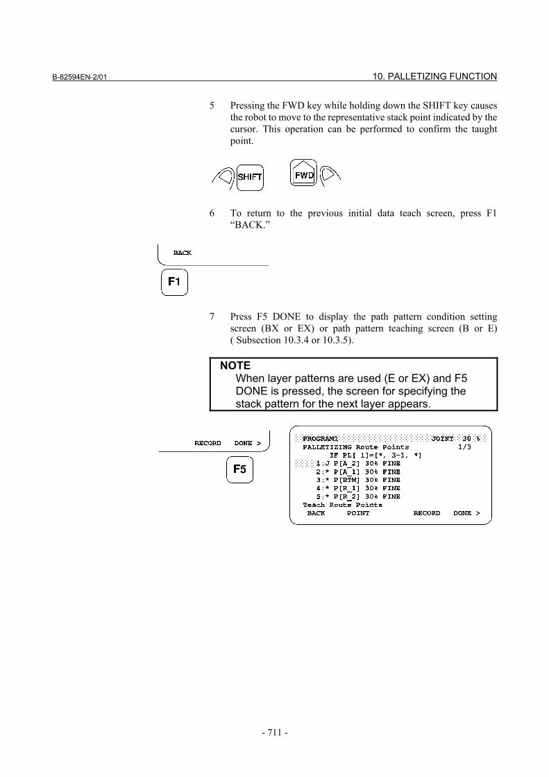
5 Pressing the FWD key while holding down the SHIFT key causes the robot to move to the representative stack point indicated by the cursor. This operation can be performed to confirm the taught point.
6 To return to the previous initial data teach screen, press F1
“BACK.”
7 Press F5 DONE to display the path pattern condition setting
screen (BX or EX) or path pattern teaching screen (B or E) ( Subsection 10.3.4 or 10.3.5).
NOTE When layer patterns are used (E or EX) and F5
DONE is pressed, the screen for specifying the stack pattern for the next layer appears.
10. PALLETIZING FUNCTION B-82594EN-2/01
- 712 -
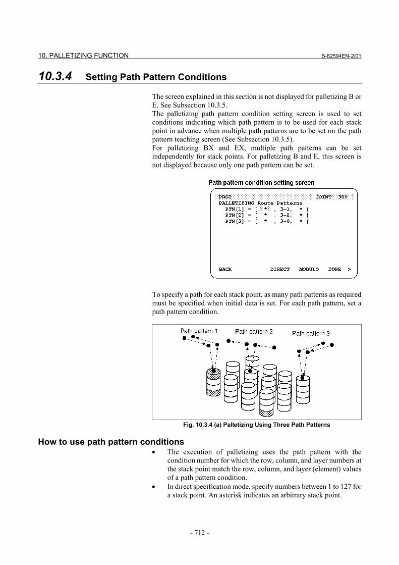
10.3.4 Setting Path Pattern Conditions The screen explained in this section is not displayed for palletizing B or E. See Subsection 10.3.5. The palletizing path pattern condition setting screen is used to set conditions indicating which path pattern is to be used for each stack point in advance when multiple path patterns are to be set on the path pattern teaching screen (See Subsection 10.3.5). For palletizing BX and EX, multiple path patterns can be set independently for stack points. For palletizing B and E, this screen is not displayed because only one path pattern can be set.
To specify a path for each stack point, as many path patterns as required must be specified when initial data is set. For each path pattern, set a path pattern condition.
Fig. 10.3.4 (a) Palletizing Using Three Path Patterns
How to use path pattern conditions
• The execution of palletizing uses the path pattern with the condition number for which the row, column, and layer numbers at the stack point match the row, column, and layer (element) values of a path pattern condition.
• In direct specification mode, specify numbers between 1 to 127 for a stack point. An asterisk indicates an arbitrary stack point.
B-82594EN-2/01 10. PALLETIZING FUNCTION
- 713 -
• In the remainder specification mode, specify path pattern condition element ”m-n” using a remainder system for a stack point.
Layer element ”3-1” indicates a layer corresponding to a stack point value for which a remainder of 1 is obtained by dividing the value by 3.
• If the current stack point corresponds to no path pattern condition, an alarm occurs. If the current stack point corresponds to two or more path pattern conditions, a path pattern condition is used according to the following conditions: a. A path pattern condition specified in direct specification
mode is used. b. When two or more path pattern conditions are specified in
direct specification mode, a path pattern condition specified in the remainder specification mode is used. When two or more path pattern conditions are specified in remainder specification mode, a path pattern condition in which the greatest value is specified for m is used.
c. When two or more path pattern conditions satisfy conditions a and b above, the path pattern condition having the smallest path pattern condition number is used.
The following shows the priority among the sample path pattern conditions:
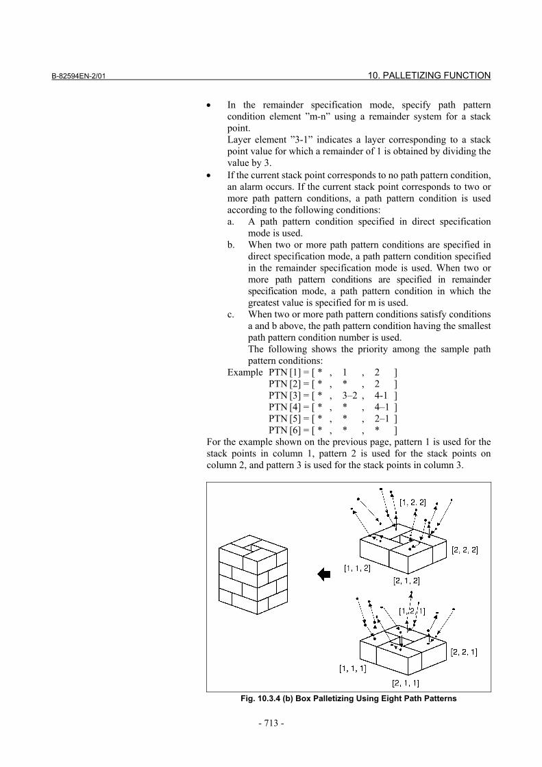
Example PTN [1] = [ * , 1 , 2 ] PTN [2] = [ * , * , 2 ] PTN [3] = [ * , 3–2 , 4-1 ] PTN [4] = [ * , * , 4–1 ] PTN [5] = [ * , * , 2–1 ] PTN [6] = [ * , * , * ]
For the example shown on the previous page, pattern 1 is used for the stack points in column 1, pattern 2 is used for the stack points on column 2, and pattern 3 is used for the stack points in column 3.
Fig. 10.3.4 (b) Box Palletizing Using Eight Path Patterns
10. PALLETIZING FUNCTION B-82594EN-2/01
- 714 -
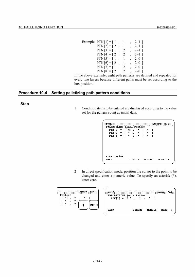
Example PTN [1] = [ 1 , 1 , 2–1 ] PTN [2] = [ 2 , 1 , 2–1 ] PTN [3] = [ 1 , 2 , 2–1 ] PTN [4] = [ 2 , 2 , 2–1 ] PTN [5] = [ 1 , 1 , 2–0 ] PTN [6] = [ 2 , 1 , 2–0 ] PTN [7] = [ 1 , 2 , 2–0 ] PTN [8] = [ 2 , 2 , 2–0 ]
In the above example, eight path patterns are defined and repeated for every two layers because different paths must be set according to the box position.
Procedure 10-4 Setting palletizing path pattern conditions
Step 1 Condition items to be entered are displayed according to the value
set for the pattern count as initial data.
2 In direct specification mode, position the cursor to the point to be
changed and enter a numeric value. To specify an asterisk (*), enter zero.
B-82594EN-2/01 10. PALLETIZING FUNCTION
- 715 -
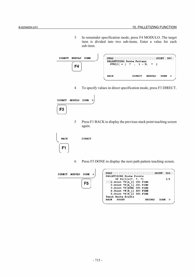
3 In remainder specification mode, press F4 MODULO. The target item is divided into two sub-items. Enter a value for each sub-item.
4 To specify values in direct specification mode, press F3 DIRECT.
5 Press F1 BACK to display the previous stack point teaching screen
again.
6 Press F5 DONE to display the next path pattern teaching screen.
10. PALLETIZING FUNCTION B-82594EN-2/01
- 716 -
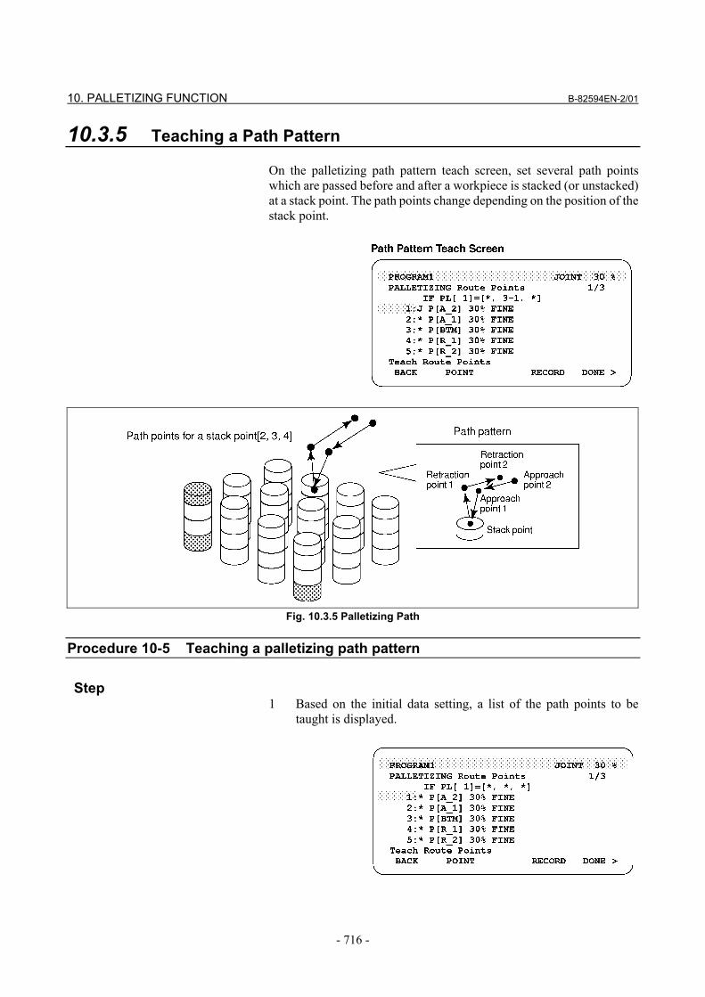
10.3.5 Teaching a Path Pattern On the palletizing path pattern teach screen, set several path points which are passed before and after a workpiece is stacked (or unstacked) at a stack point. The path points change depending on the position of the stack point.
Fig. 10.3.5 Palletizing Path
Procedure 10-5 Teaching a palletizing path pattern
Step
1 Based on the initial data setting, a list of the path points to be taught is displayed.
B-82594EN-2/01 10. PALLETIZING FUNCTION
- 717 -
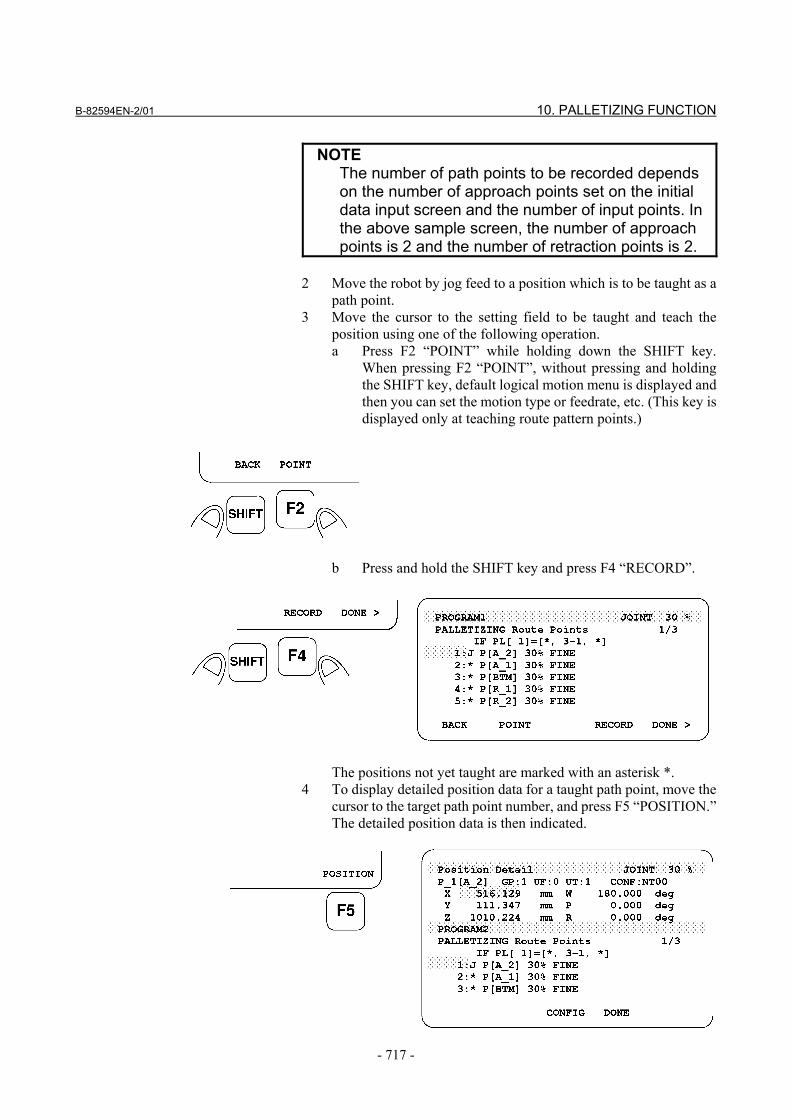
NOTE The number of path points to be recorded depends
on the number of approach points set on the initial data input screen and the number of input points. In the above sample screen, the number of approach points is 2 and the number of retraction points is 2.
2 Move the robot by jog feed to a position which is to be taught as a
path point. 3 Move the cursor to the setting field to be taught and teach the
position using one of the following operation. a Press F2 “POINT” while holding down the SHIFT key.
When pressing F2 “POINT”, without pressing and holding the SHIFT key, default logical motion menu is displayed and then you can set the motion type or feedrate, etc. (This key is displayed only at teaching route pattern points.)
b Press and hold the SHIFT key and press F4 “RECORD”.
The positions not yet taught are marked with an asterisk *. 4 To display detailed position data for a taught path point, move the
cursor to the target path point number, and press F5 “POSITION.” The detailed position data is then indicated.
10. PALLETIZING FUNCTION B-82594EN-2/01
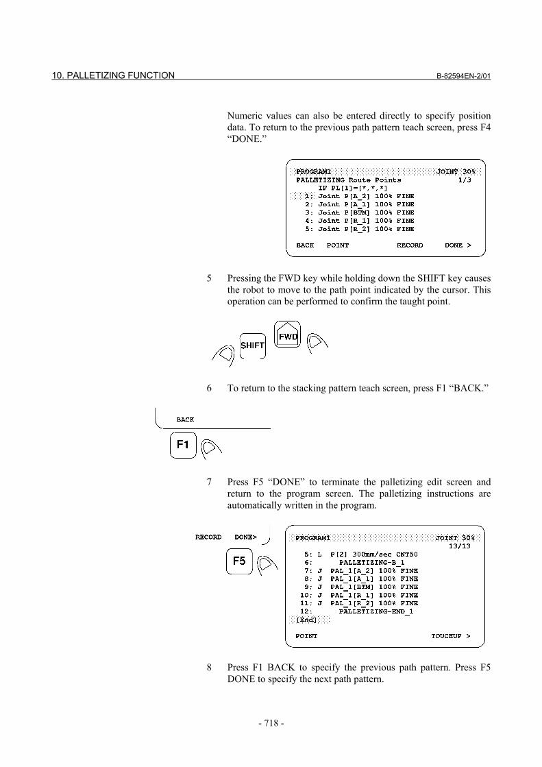
- 718 -
Numeric values can also be entered directly to specify position
data. To return to the previous path pattern teach screen, press F4 “DONE.”
5 Pressing the FWD key while holding down the SHIFT key causes
the robot to move to the path point indicated by the cursor. This operation can be performed to confirm the taught point.
6 To return to the stacking pattern teach screen, press F1 “BACK.”
7 Press F5 “DONE” to terminate the palletizing edit screen and
return to the program screen. The palletizing instructions are automatically written in the program.
8 Press F1 BACK to specify the previous path pattern. Press F5
DONE to specify the next path pattern.
B-82594EN-2/01 10. PALLETIZING FUNCTION
- 719 -
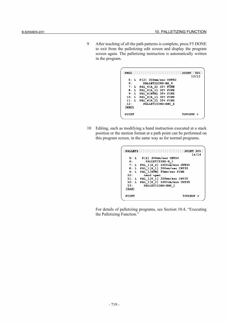
9 After teaching of all the path patterns is complete, press F5 DONE to exit from the palletizing edit screen and display the program screen again. The palletizing instruction is automatically written in the program.
10 Editing, such as modifying a hand instruction executed at a stack
position or the motion format at a path point can be performed on this program screen, in the same way as for normal programs.
For details of palletizing programs, see Section 10.4, “Executing
the Palletizing Function.”
10. PALLETIZING FUNCTION B-82594EN-2/01
- 720 -
10.3.6 Notes on Teaching the Palletizing Function • The palletizing function is enabled only when a program contains
these three instructions: A palletizing instruction, palletizing motion instruction, and palletizing end instruction. When just one of the three instructions is taught into a subprogram by another operation such as copying, normal operation cannot be performed.
• When all palletizing data has been taught, palletizing numbers are automatically written together with the instructions (a palletizing instruction, palletizing motion instruction, and palletizing end instruction). The user need not be concerned about the duplication of these numbers in other programs. (Each program has its own data for palletizing numbers.)
• In the palletizing motion instruction, C (circular motion) cannot be specified as the motion format.
• When palletizing, with a system with extended axes, there are some special conditions. For a system with extended axes, refer to Section 10.6 ”Palletizing Function with extended axes”
B-82594EN-2/01 10. PALLETIZING FUNCTION
- 721 -
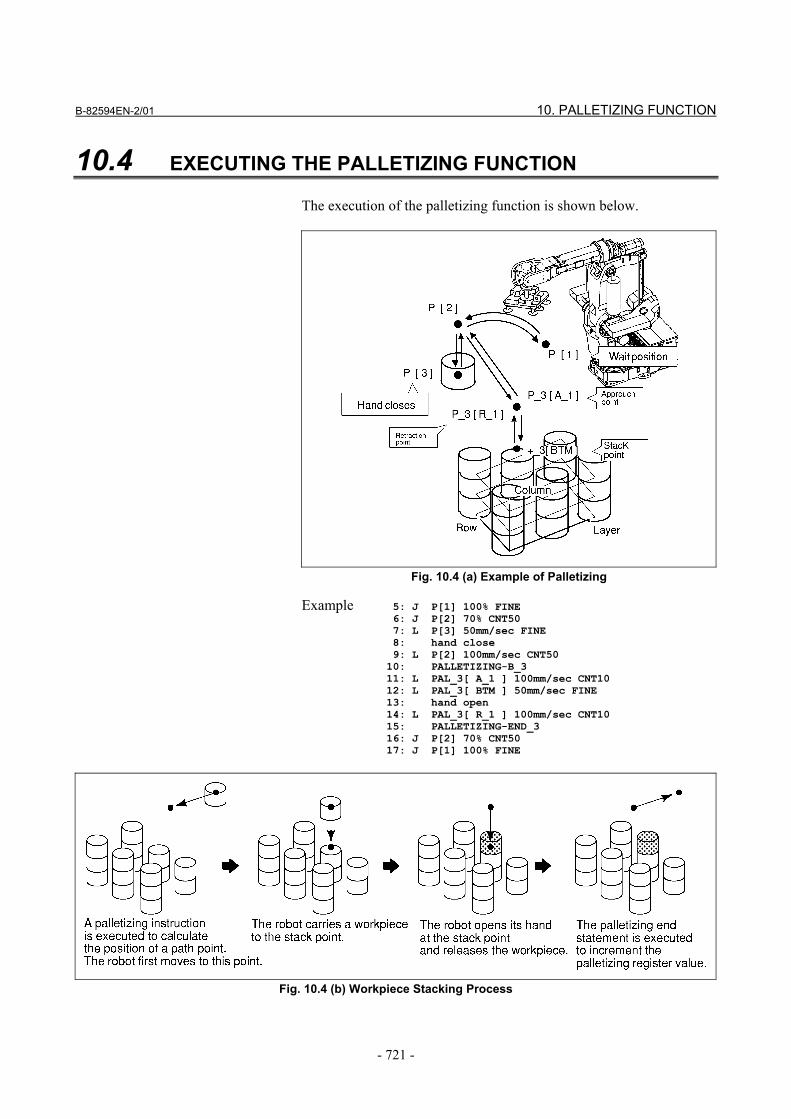
10.4 EXECUTING THE PALLETIZING FUNCTION The execution of the palletizing function is shown below.
Fig. 10.4 (a) Example of Palletizing
Example 5: J P[1] 100% FINE 6: J P[2] 70% CNT50 7: L P[3] 50mm/sec FINE 8: hand close 9: L P[2] 100mm/sec CNT50 10: PALLETIZING-B_3 11: L PAL_3[ A_1 ] 100mm/sec CNT10 12: L PAL_3[ BTM ] 50mm/sec FINE 13: hand open 14: L PAL_3[ R_1 ] 100mm/sec CNT10 15: PALLETIZING-END_3 16: J P[2] 70% CNT50 17: J P[1] 100% FINE
Fig. 10.4 (b) Workpiece Stacking Process
10. PALLETIZING FUNCTION B-82594EN-2/01
- 722 -
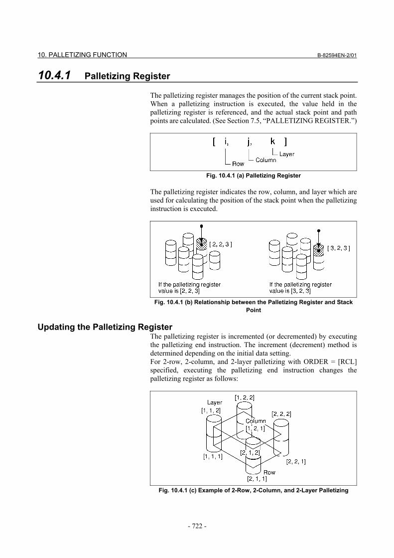
10.4.1 Palletizing Register The palletizing register manages the position of the current stack point. When a palletizing instruction is executed, the value held in the palletizing register is referenced, and the actual stack point and path points are calculated. (See Section 7.5, “PALLETIZING REGISTER.”)
Fig. 10.4.1 (a) Palletizing Register
The palletizing register indicates the row, column, and layer which are used for calculating the position of the stack point when the palletizing instruction is executed.
Fig. 10.4.1 (b) Relationship between the Palletizing Register and Stack Point
Updating the Palletizing Register
The palletizing register is incremented (or decremented) by executing the palletizing end instruction. The increment (decrement) method is determined depending on the initial data setting. For 2-row, 2-column, and 2-layer palletizing with ORDER = [RCL] specified, executing the palletizing end instruction changes the palletizing register as follows:
Fig. 10.4.1 (c) Example of 2-Row, 2-Column, and 2-Layer Palletizing
B-82594EN-2/01 10. PALLETIZING FUNCTION
- 723 -
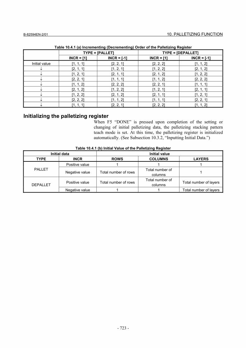
Table 10.4.1 (a) Incrementing (Decrementing) Order of the Palletizing Register TYPE = [PALLET] TYPE = [DEPALLET]
INCR = [1] INCR = [-1] INCR = [1] INCR = [-1] Initial value [1, 1, 1] [2, 2, 1] [2, 2, 2] [1, 1, 2]
↓ [2, 1, 1] [1, 2, 1] [1, 2, 2] [2, 1, 2] ↓ [1, 2, 1] [2, 1, 1] [2, 1, 2] [1, 2, 2] ↓ [2, 2, 1] [1, 1, 1] [1, 1, 2] [2, 2, 2] ↓ [1, 1, 2] [2, 2, 2] [2, 2, 1] [1, 1, 1] ↓ [2, 1, 2] [1, 2, 2] [1, 2, 1] [2, 1, 1] ↓ [1, 2, 2] [2, 1, 2] [2, 1, 1] [1, 2, 1] ↓ [2, 2, 2] [1, 1, 2] [1, 1, 1] [2, 2, 1] ↓ [1, 1, 1] [2, 2, 1] [2, 2, 2] [1, 1, 2]
Initializing the palletizing register
When F5 “DONE” is pressed upon completion of the setting or changing of initial palletizing data, the palletizing stacking pattern teach mode is set. At this time, the palletizing register is initialized automatically. (See Subsection 10.3.2, “Inputting Initial Data.”)
Table 10.4.1 (b) Initial Value of the Palletizing Register Initial data Initial value
TYPE INCR ROWS COLUMNS LAYERS Positive value 1 1 1
PALLET Negative value Total number of rows
Total number of columns
1
Positive value Total number of rowsTotal number of
columns Total number of layers
DEPALLET Negative value 1 1 Total number of layers
10. PALLETIZING FUNCTION B-82594EN-2/01
- 724 -
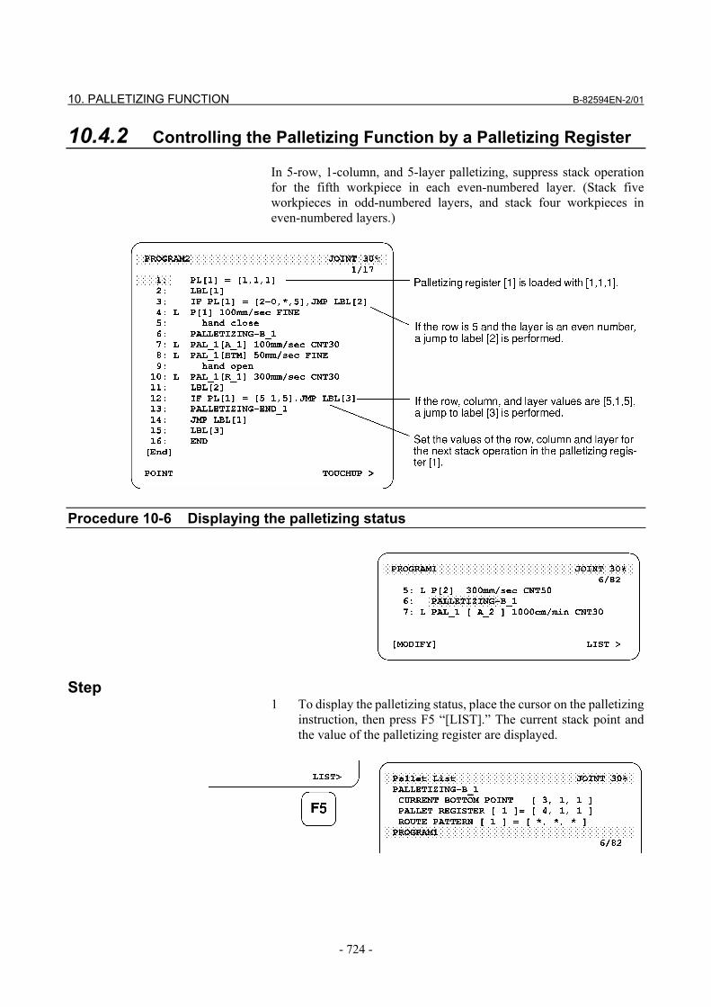
10.4.2 Controlling the Palletizing Function by a Palletizing Register In 5-row, 1-column, and 5-layer palletizing, suppress stack operation for the fifth workpiece in each even-numbered layer. (Stack five workpieces in odd-numbered layers, and stack four workpieces in even-numbered layers.)
Procedure 10-6 Displaying the palletizing status
Step 1 To display the palletizing status, place the cursor on the palletizing
instruction, then press F5 “[LIST].” The current stack point and the value of the palletizing register are displayed.
B-82594EN-2/01 10. PALLETIZING FUNCTION
- 725 -
10.5 MODIFYING THE PALLETIZING FUNCTION Modifying the palletizing function The palletizing data and palletizing instructions which were taught can be modified later.
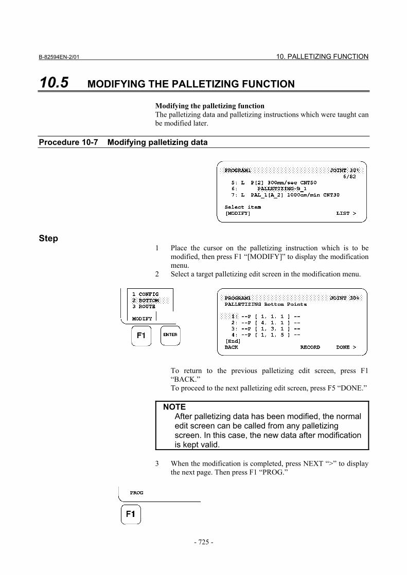
Procedure 10-7 Modifying palletizing data
Step 1 Place the cursor on the palletizing instruction which is to be
modified, then press F1 “[MODIFY]” to display the modification menu.
2 Select a target palletizing edit screen in the modification menu.
To return to the previous palletizing edit screen, press F1
“BACK.” To proceed to the next palletizing edit screen, press F5 “DONE.”
NOTE After palletizing data has been modified, the normal
edit screen can be called from any palletizing screen. In this case, the new data after modification is kept valid.
3 When the modification is completed, press NEXT “>” to display
the next page. Then press F1 “PROG.”
10. PALLETIZING FUNCTION B-82594EN-2/01
- 726 -
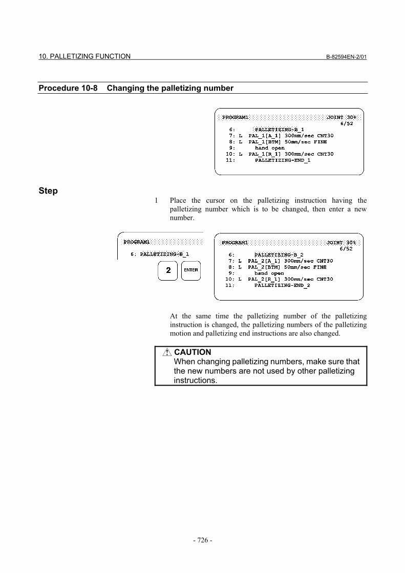
Procedure 10-8 Changing the palletizing number
Step 1 Place the cursor on the palletizing instruction having the
palletizing number which is to be changed, then enter a new number.
At the same time the palletizing number of the palletizing
instruction is changed, the palletizing numbers of the palletizing motion and palletizing end instructions are also changed.
CAUTION
When changing palletizing numbers, make sure that the new numbers are not used by other palletizing instructions.
B-82594EN-2/01 10. PALLETIZING FUNCTION
- 727 -
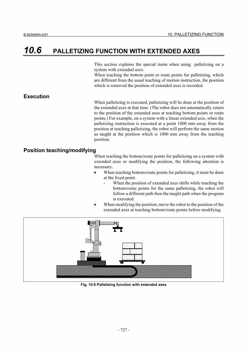
10.6 PALLETIZING FUNCTION WITH EXTENDED AXES This section explains the special items when using palletizing on a system with extended axes. When teaching the bottom point or route points for palletizing, which are different from the usual teaching of motion instruction, the position which is removed the position of extended axes is recorded.
Execution When palletizing is executed, palletizing will be done at the position of the extended axes at that time. (The robot does not automatically return to the position of the extended axes at teaching bottom points or route points.) For example, on a system with a linear extended axis, when the palletizing instruction is executed at a point 1000 mm away from the position at teaching palletizing, the robot will perform the same motion as taught at the position which is 1000 mm away from the teaching position.
Position teaching/modifying When teaching the bottom/route points for palletizing on a system with extended axes or modifying the position, the following attention is necessary. • When teaching bottom/route points for palletizing, it must be done
at the fixed point. - When the position of extended axes shifts while teaching the
bottom/route points for the same palletizing, the robot will follow a different path then the taught path when the program is executed.
• When modifying the position, move the robot to the position of the extended axes at teaching bottom/route points before modifying.
Fig. 10.6 Palletizing function with extended axes
10. PALLETIZING FUNCTION B-82594EN-2/01
- 728 -
10.7 PALLETIZING ALL-POINT TEACHING Palletizing all-point teaching allows the stacking (or unloading) of workpieces without changing the taught form by changing a system variable.
Operation Set the following values to stack (or unload) workpieces without changing the taught attitude and form: 1 On the system variable screen, set system variable
$PALCFG.$FREE_CFG_EN to TRUE (the initial value is TRUE).
2 On the palletizing initial data screen, set INTER for attitude control in the row, column, or layer direction for which FREE is specified as the arrangement mode.
For each taught workpiece in the specified direction, all
workpieces corresponding to the taught workpiece are stacked (or unloaded) with the same attitude and form as that for the taught workpiece.
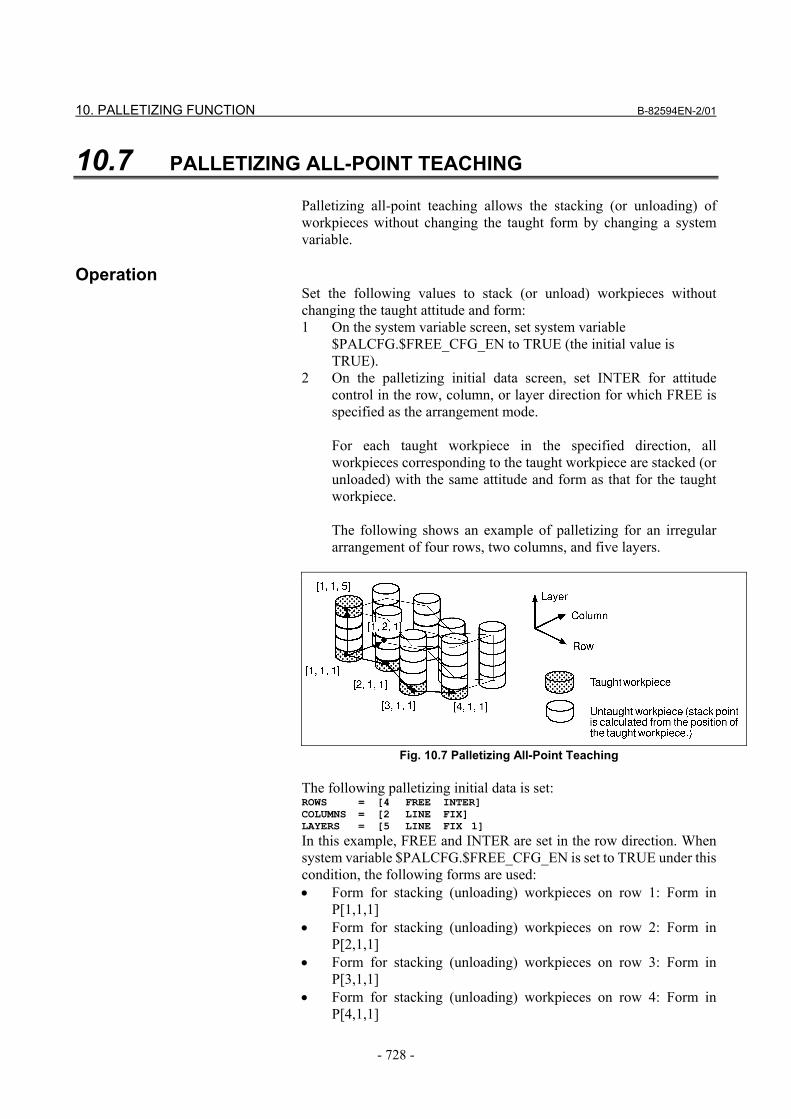
The following shows an example of palletizing for an irregular
arrangement of four rows, two columns, and five layers.
Fig. 10.7 Palletizing All-Point Teaching The following palletizing initial data is set: ROWS = [4 FREE INTER] COLUMNS = [2 LINE FIX] LAYERS = [5 LINE FIX 1]
In this example, FREE and INTER are set in the row direction. When system variable $PALCFG.$FREE_CFG_EN is set to TRUE under this condition, the following forms are used: • Form for stacking (unloading) workpieces on row 1: Form in
P[1,1,1] • Form for stacking (unloading) workpieces on row 2: Form in
P[2,1,1] • Form for stacking (unloading) workpieces on row 3: Form in
P[3,1,1] • Form for stacking (unloading) workpieces on row 4: Form in
P[4,1,1]
B-82594EN-2/01 10. PALLETIZING FUNCTION
- 729 -
Notes
Note the following points when using this function: 1 FREE and INTER can be set at the same time in only one of the
row, column, and layer directions (when this function is not to be used, set system variable $PALCFG.$FREE_CFG_EN to FALSE).
This is because if FREE and INTER are set at the same time in two
or more of the row, column, and layer directions, two or more forms to be taken at the position of an untaught workpiece (workpiece for which the stack point is calculated from the position of a taught workpiece) are made.
If such a setting is made in a program, the program causes the error
indicated by PALT-024 Calculation error occurred and cannot be executed.
2 Carefully teach a program so that the program is not stopped due to a form mismatch alarm.
If the form in the current position differs from the form data for the
destination position, the robot cannot move in Linear operation mode (a form mismatch alarm occurs and execution of the program is stopped).
The form at a stack point is used for the form at an approach or
retraction point during palletizing. Therefore, if the pallet operation instruction to be executed first is in Linear operation mode, a form mismatch may occur depending on the form of the robot when an attempt is made to execute the line.
To avoid such a problem, specify Joint for the operation mode of
the first pallet operation instruction. For example, to avoid a form mismatch alarm, the following
programming can be used for palletizing with three approach points and two retraction points.
: 10:PLLETIZING-EX_1 11:J PAL_1[A_3] 100% FINE 12:L PAL_1[A_2] 500mm/sec CNT50 13:L PAL_1[A_1] 300mm/sec CNT10 14:L PAL_1[BTM] 100mm/sec FINE 15:Open hand 1 16:L PAL_1[R_1] 300mm/sec CNT10 17:L PAL_1[R_2] 500mm/sec CNT50 18:PALLETIZING-END_1 :


