
Parameter Guide
01Copyright © 2017 ROLAND CORPORATION

Contents
Detailed Settings for a Program (Program Edit) 4
Detailed Settings for Each Zone (Zone Edit) 4
Changing the Key Touch (Key Touch) 5
Assigning Functions to Pedals (Pedal) 6
Assigning Functions to Controllers (Assign) 7
List of Functions Assignable to Pedals, Knobs, and Buttons 8
Adding Reverberation to the Sound (Reverb) 9
Adding Spaciousness to the Sound (Delay) 9
Adjusting the Levels of Each Frequency Range (EQUALIZER) 9
Detailed Tone Settings (TONE DESIGNER) 10
Piano Designer 10
Tone Designer 12
Making Detailed Settings for the E. Piano Tones 12
Making Detailed Settings for the CLAV Tones 13
Making Detailed Settings for the Other Tones 13
Editing Individual Keys (Indiv. Voicing) 14
Adjusting Resonance When the Damper Pedal Is Depressed (Sym. Resonance) 15
Editing the Modulation FX (Modulation FX) 15
Editing Tremolo/Amp Simulator (Tremolo/Amp Simulator) 16
Simulating the Creation of Organ Tones 17
Using the RD-2000 as a Master Keyboard 18
What’s MIDI? 18
About MIDI Connectors 18
Adjusting the Volume of Each Zone 18
Selecting the MIDI Connector to Use for Output 18
Setting the MIDI Transmit Channel 19
Selecting Sounds on an External MIDI Device 19
Detailed Settings for Transmitted Parts 19
Detailed Settings for Each Function 22
Setting Parameters (System) 22
Tuning to Other Instruments’ Pitches (Master Tune) 22
Selecting the Target Controlled by a Knob (Control Destination) 22
Retaining the Equalizer Settings Even When the Program Is Switched (EQ Mode) 22
Retaining the SELECT Button Settings Even When the Program Is Switched (Select Button Mode) 22
Retaining the Pedal Settings Even When the Program Is Switched (Pedal Mode) 22
Retaining the MOD WHEEL 1/2 Settings Even When the Program Is Switched (Wheel Mode) 22
Retaining the Assign 1–9 Controller Settings Even When the Program Is Switched (Assign 1-9 Mode) 23
Retaining the Delay Settings Even When the Program Is Switched (Delay Mode) 23
Retaining the Reverb Settings Even When the Program Is Switched (Reverb Mode) 23
Retaining the Rhythm Settings Even When the Program Is Switched (Rhythm Mode) 23
Retaining the Keyboard Touch Settings Even When the Tone or Program Is Switched (Key Touch Mode) 23
Retaining the Current Tone Even When Tones Are Switched (Tone/Program Remain) 24
Retaining the Ext Zone On/Off Settings Even When Tones Are Switched (Tone Ext Zone Remain) 24
Preventing Ctrl Messages from Being Transmitted by Ext Zone On/Off (Ext Zone Transmit Control) 24
Selecting the USB Driver (USB Driver) 24
Selecting the USB MIDI Thru Switch (USB MIDI Thru Switch) 24
Selecting the Function of the MIDI THRU/OUT 2 Connector (MIDI OUT2 Port Mode) 24
Switching the Pedal’s Polarity (Damper/FC1/FC2/EXT Pedal Polarity) 25
Setting the Tuning Method (Temperament/Key) 25
Transmitting Synchronization Messages (Clock Out) 25
Transmitting High-Resolution Velocity Data (Hi-Res Velocity Out ) 25
Selecting the MIDI Output Port for Rhythm (Rhythm MIDI Output Port) 25
Selecting the MIDI Output Channel for Rhythm (Rhythm MIDI Channel) 25
Adjusting the Playback Volume of Audio Files 25
Outputting the SUB OUT Output from MAIN OUT (Output Mix/Parallel) 26
Adjusting the Brightness of the Display (LCD Brightness) 26
Making the Power Automatically Turn Off After a Time (Auto Off) 26
Saving System Settings 26
USB Audio Settings 26
Selecting the Parts That Will Produce Sound (PART SW) 27
Making the System Compressor Settings (COMPRESSOR) 27
INFORMATION 27
Convenient Functions (Utility) 28
Saving a Program File (Program File Save) 28
Calling Up Program Files (Backup Load) 28
Deleting a Program File (Backup Delete) 29
Formatting Memory (Format) 29
Returning to the Factory Settings (Factory Reset) 29
SCENE UTILITY 30
Changing the Order of Scenes (Scene Swap) 30
Initializing a Scene (Scene Initialize) 30
Adding a Memo to Each Scene (Scene Memo) 30
Importing Text to Display as the Scene Memo (Scene Memo Import) 31
Exporting a Scene as a Program and Saving It (Scene To Program) 31
Deleting a Scene (Scene Remove) 31
Other Functions 32
Local Ctrl 32
Disconnecting the Controller Section and the Sound Generator Section (Local Switch) 32
Optimizing Settings for Recording on an External Sequencer (Rec Mode) 32
Selecting the EXP Category 32
Connecting to Your Computer 33
Connecting to a Computer via the USB COMPUTER Port 33
Switching USB Drivers 33
Using the RD-2000 as a USB MIDI Interface 33
2

Contents
Modulation FX Parameters 34
Tremolo/Amp Simulator Parameters 61
Sympathetic Resonance Parameters 64
Delay Parameters 65
Reverb Parameters 67
EQ Parameters 68
System Compressor Parameters 69
Tone List 70
CONCERT 70
STUDIO 70
VINTAGE 70
MODERN 71
CLAV 71
ORGAN 72
STRINGS 73
PAD/CHOIR 73
BASS 74
OTHER 76
Program List 80
A 80
B 80
C 80
D 80
E 81
F 81
G 81
H 81
I 82
J 82
K 82
L 82
M 83
N 83
O 83
3
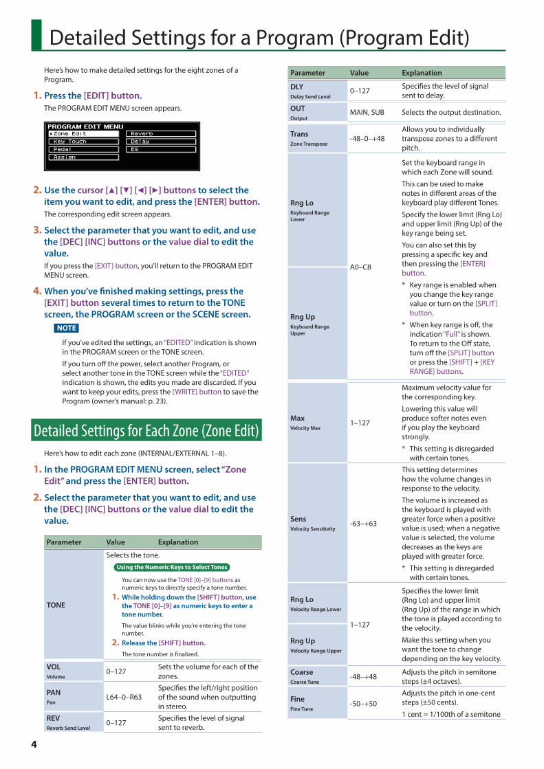
Detailed Settings for a Program (Program Edit)Here’s how to make detailed settings for the eight zones of a Program.
1 Press the [EDIT] button.The PROGRAM EDIT MENU screen appears.
2 Use the cursor [H] [I] [K] [J] buttons to select the item you want to edit, and press the [ENTER] button.The corresponding edit screen appears.
3 Select the parameter that you want to edit, and use the [DEC] [INC] buttons or the value dial to edit the value.If you press the [EXIT] button, you'll return to the PROGRAM EDIT MENU screen.
4 When you’ve finished making settings, press the [EXIT] button several times to return to the TONE screen, the PROGRAM screen or the SCENE screen.
NOTE
If you’ve edited the settings, an “EDITED” indication is shown in the PROGRAM screen or the TONE screen.
If you turn off the power, select another Program, or select another tone in the TONE screen while the “EDITED” indication is shown, the edits you made are discarded. If you want to keep your edits, press the [WRITE] button to save the Program (owner’s manual: p. 23).
Detailed Settings for Each Zone (Zone Edit)Here’s how to edit each zone (INTERNAL/EXTERNAL 1–8).
1 In the PROGRAM EDIT MENU screen, select “Zone Edit” and press the [ENTER] button.
2 Select the parameter that you want to edit, and use the [DEC] [INC] buttons or the value dial to edit the value.
Parameter Value Explanation
TONE
Selects the tone.Using the Numeric Keys to Select Tones
You can now use the TONE [0]–[9] buttons as numeric keys to directly specify a tone number.
1 While holding down the [SHIFT] button, use the TONE [0]–[9] as numeric keys to enter a tone number.
The value blinks while you’re entering the tone number.
2 Release the [SHIFT] button.
The tone number is finalized.
VOLVolume
0–127 Sets the volume for each of the zones.
PANPan
L64–0–R63Specifies the left/right position of the sound when outputting in stereo.
REVReverb Send Level
0–127 Specifies the level of signal sent to reverb.
Parameter Value Explanation
DLYDelay Send Level
0–127 Specifies the level of signal sent to delay.
OUTOutput
MAIN, SUB Selects the output destination.
TransZone Transpose
-48–0–+48Allows you to individually transpose zones to a different pitch.
Rng LoKeyboard Range Lower
A0–C8
Set the keyboard range in which each Zone will sound.
This can be used to make notes in different areas of the keyboard play different Tones.
Specify the lower limit (Rng Lo) and upper limit (Rng Up) of the key range being set.
You can also set this by pressing a specific key and then pressing the [ENTER] button.
* Key range is enabled when you change the key range value or turn on the [SPLIT] button.
* When key range is off, the indication “Full” is shown. To return to the Off state, turn off the [SPLIT] button or press the [SHIFT] + [KEY RANGE] buttons.
Rng UpKeyboard Range Upper
MaxVelocity Max
1–127
Maximum velocity value for the corresponding key.
Lowering this value will produce softer notes even if you play the keyboard strongly.
* This setting is disregarded with certain tones.
SensVelocity Sensitivity
-63–+63
This setting determines how the volume changes in response to the velocity.
The volume is increased as the keyboard is played with greater force when a positive value is used; when a negative value is selected, the volume decreases as the keys are played with greater force.
* This setting is disregarded with certain tones.
Rng LoVelocity Range Lower
1–127
Specifies the lower limit (Rng Lo) and upper limit (Rng Up) of the range in which the tone is played according to the velocity.
Make this setting when you want the tone to change depending on the key velocity.
Rng UpVelocity Range Upper
CoarseCoarse Tune
-48–+48 Adjusts the pitch in semitone steps (±4 octaves).
FineFine Tune
-50–+50Adjusts the pitch in one-cent steps (±50 cents).
1 cent = 1/100th of a semitone
4
Detailed Settings for a Program (Program Edit)
Parameter Value Explanation
VC RESVoice Reserve
0–63, Full
Specifies the number of voices that will be reserved for each zone if you attempt to play more than 128 voices.
DamperDamper Control Switch
ON, OFF
Specifies whether the damper pedal will (ON) or will not (OFF) control each zone.
FC1FC1 Control Switch
Specifies whether the pedal connected to the FC1 jack will (ON) or will not (OFF) control each zone. (*1)
FC2FC2 Control Switch
Specifies whether the pedal connected to the FC2 jack will (ON) or will not (OFF) control each zone. (*1)
EXTEXT Pedal Control Switch
Specifies whether the pedal connected to the EXT jack will (ON) or will not (OFF) control each zone. (*1)
PCH BND
Pitch Bend Control Switch
ON, OFF
Specifies whether the pitch bend lever will (ON) or will not (OFF) control each zone.
MOD CTLModulation Control Switch
Specifies whether the modulation lever will (ON) or will not (OFF) control each zone.
MOD W1Mod Wheel 1 Control Switch
Specifies whether the MOD WHEEL 1 will (ON) or will not (OFF) control each zone. (*1)
MOD W2Mod Wheel 2 Control Switch
Specifies whether the MOD WHEEL 2 will (ON) or will not (OFF) control each zone. (*1)
A1Assign 1 Control Switch
ON, OFF
Specifies whether the ASSIGN [1] knob will (ON) or will not (OFF) control each zone. (*1)
A2Assign 2 Control Switch
Specifies whether the ASSIGN [2] knob will (ON) or will not (OFF) control each zone. (*1)
A3Assign 3 Control Switch
Specifies whether the ASSIGN [3] knob will (ON) or will not (OFF) control each zone. (*1)
A4Assign 4 Control Switch
Specifies whether the ASSIGN [4] knob will (ON) or will not (OFF) control each zone. (*1)
A5Assign 5 Control Switch
Specifies whether the ASSIGN [5] knob will (ON) or will not (OFF) control each zone. (*1)
A6Assign 6 Control Switch
Specifies whether the ASSIGN [6] knob will (ON) or will not (OFF) control each zone. (*1)
A7Assign 7 Control Switch
Specifies whether the ASSIGN [7] knob will (ON) or will not (OFF) control each zone. (*1)
A8Assign 8 Control Switch
Specifies whether the ASSIGN [8] knob will (ON) or will not (OFF) control each zone. (*1)
A9Assign 9 Control Switch
Specifies whether the ASSIGN [9] button will (ON) or will not (OFF) control each zone. (*1)
Parameter Value Explanation
TON CLRTone Color Control Destination
Select one zone
Select the zone that you want to control using the [TONE COLOR] knob. (* 2)
MOD FXModulation FX Control Destination
Select the zone that you want to control using the MODULATION FX [DEPTH] and [RATE] knobs and [ON/OFF] button. (* 2)
TR/AMPTremolo/Amp Control Destination
Select the zone that you want to control using the TREMOLO [DEPTH] and [RATE] knobs and [ON/OFF] button, and the AMP SIM [DRIVE] knob and [ON/OFF] button. (* 2)
*1 The parameters that can control each zone are the parameters indicated by (*1) in the “List of Functions Assignable to Pedals, Knobs, and Buttons” (p. 8).
*2 This parameter is enabled only when the SYSTEM setting “Control Destination” is PROGRAM.
Changing the Key Touch (Key Touch)The setting below allows you to adjust the response you get from the keyboard when you finger the keys.
1 Either press the [KEY TOUCH] button, or use the PROGRAM EDIT MENU screen to select “Key Touch” and press the [ENTER] button (p. 4).
2 Select the parameter that you want to edit, and use the [DEC] [INC] buttons or the value dial to edit the value.
Parameter Value Explanation
Key Touch
SUPER LIGHT An even lighter setting than LIGHT.
LIGHT
Sets the keyboard to a light touch. You can achieve fortissimo (ff) play with a less forceful touch than MEDIUM, so the keyboard feels lighter. This setting makes it easy to play, even for children.
MEDIUM
Sets the keyboard to the standard touch. You can play with the most natural touch. This is the closest to the touch of an acoustic piano.
HEAVY
Sets the keyboard to a heavy touch. You have to finger the keyboard more forcefully than MEDIUM in order to play fortissimo (ff), so the keyboard touch feels heavier. Dynamic fingering adds even more feeling to what you play.
SUPER HEAVY An even heavier setting than HEAVY.
5

Detailed Settings for a Program (Program Edit)
Parameter Value Explanation
Key Touch Offset -10–+9
This setting provides even more precise adjustment of the key touch than available with the Key Touch setting alone.
The touch sensitivity becomes heavier as the value increases.
When this parameter is set to a value that exceeds the upper or lower limit, the setting for Key Touch (one of five possible values) is automatically changed to accommodate the value you’ve specified.
Velocity
REALVolume levels and the way sounds are played change in response to the velocity.
1–127
Regardless of how strongly you play the keyboard, volume levels and the way sounds are played always reflect the fixed velocity value you specify here.
Velo Delay Sens -63–+63
As the value is decreased, the timing of the sound is delayed more when more force is used to play the keys. As the value is increased, the timing of the sound is delayed more when less force is used to play the keys.
Velo Key Follow Sens -63–+63
As the value is increased, the touch becomes heavier in the upper registers, and lighter in the lower registers.
Key Off Position
STANDARD Note-off occurs at the key depth of a conventional piano.
DEEPNote-off occurs at a deeper position. This is suitable for electric piano sounds.
Assigning Functions to Pedals (Pedal)This setting determines the function of the pedal switches (such as the optional DP series) or expression pedals (such as the optional EV-5) that are connected to the FC1, FC2, and EXT jacks on the rear panel.
1 In the PROGRAM EDIT MENU screen, select “Pedal” and press the [ENTER] button (p. 4).
2 Select the parameter that you want to edit, and use the [DEC] [INC] buttons or the value dial to edit the value.The assigned function is controlled between the minimum value (Min) and maximum value (Max). If Min is set to a greater value than Max, the change is reversed.
FC1/FC2/EXT pedals
Parameter Value Explanation
Func
(Function)
Selects the function to be assigned to each pedal.
* For details on the values, refer to “List of Functions Assignable to Pedals, Knobs, and Buttons” (p. 8).
Range Min 0–127 Specifies the value when the pedal is not pressed (minimum value) (*1).
Range Max 0–127 Specifies the value when the pedal is advanced to its fullest extent (maximum value) (*1).
MEMO
By specifying the Range Min/Max settings, you’ll be able to control the function in the desired range; this will help you obtain the performance result that you want.
*1 Depending on the function that you assign, the value might not have the range of 0–127. In this case, the setting of 0–127 is converted appropriately for the function that's assigned. If you assign a function that is switched on/off, it turns off at Min and turns on at Max. If you assign an on/off function to an expression pedal, it switches on/off at the value that is mid-way between Min and Max.
6

Detailed Settings for a Program (Program Edit)
Assigning Functions to Controllers (Assign)Here’s how to assign functions to the MOD WHEEL 1/2, the ASSIGN [1]–[8] knobs and the ASSIGN [9] button.
1 In the PROGRAM EDIT MENU screen, select “Assign” and press the [ENTER] button (p. 4).
2 Select the parameter that you want to edit, and use the [DEC] [INC] buttons or the value dial to edit the value.
MOD WHEEL 1/2
Parameter Value Explanation
Func
(Function)
Selects the functions that are assigned to the MOD WHEEL 1/2.
* For details on the values, refer to “List of Functions Assignable to Pedals, Knobs, and Buttons” (p. 8).
ASSIGN [1]–[8] knobs
Parameter Value Explanation
Func
(Function)
Selects the functions that are assigned to the ASSIGN [1]–[8] knobs.
* For details on the values, refer to “List of Functions Assignable to Pedals, Knobs, and Buttons” (p. 8).
Range Min 0–127
Specifies the value when the ASSIGN [1]–[8] knob is turned all the way to the left (minimum value) (*1).
Range Max 0–127
Specifies the value when the ASSIGN [1]–[8] knob is turned all the way to the right (maximum value) (*1).
MEMO
By specifying the Range Min/Max settings, you’ll be able to control the function in the desired range; this will help you obtain the performance result that you want.
*1 Depending on the function that you assign, the value might not have the range of 0–127. In this case, the setting of 0–127 is converted appropriately for the function that’s assigned. If you assign a function that is switched on/off, it turns off at Min and turns on at Max.
ASSIGN [9] button
Parameter Value Explanation
Func
(Function)
Selects the function that’s assigned to the ASSIGN [9] button.
* For details on the values, refer to “List of Functions Assignable to Pedals, Knobs, and Buttons” (p. 8).
Switch Type
Specifies the operation of the button.
LATCH The function turns on/off each time you press the button.
MOMENTARY The function is on only while you hold down the button.
MEMO
Whether the Switch Type setting does anything or not depends on the function that’s assigned.
SLIDER
Parameter Value Explanation
Slider Func
Selects the functions that are assigned to the slider.
* For details on the values, refer to “List of Functions Assignable to Pedals, Knobs, and Buttons” (p. 8).
7

Detailed Settings for a Program (Program Edit)
List of Functions Assignable to Pedals, Knobs, and Buttons
Controllers to which a function can be assignedFunctions that
can be assigned ExplanationFC1 / FC2 / EXT pedal
ASSIGN [1]–[8] knob
ASSIGN [1]–[8] slider
ASSIGN [9] button Mod Wheel 1 / 2
OFF Nothing is controlled.
CC0–CC127 Controller number 0–127 (*1)
BEND DOWN Lowers the pitch just as when the pitch bend lever is moved to the left. (*1)
BEND UP Raises the pitch just as when the pitch bend lever is moved to the right. (*1)
AFTERTOUCH Controls aftertouch. (*1)
OCTAVE DOWN Lowers the key range in octave steps each time you press the button (maximum four octaves).
OCTAVE UP Raises the key range in octave steps each time you press the button (maximum four octaves).
EXT START/STOP Starts/stops an external sequencer.
TAP TEMPO Sets the tempo to match the timing you use when pressing the pedal or the button.
PLAY/STOP The same function as the [PLAY/STOP] button.
SONG RESET Returns to the beginning of the song.
SONG BWD Rewinds the song.
SONG FWD Fast-forwards the song.
MOD FX SWITCH The same function as the MODULATION FX [ON/OFF] button. (*2)
MOD FX DEPTH The same function as the MODULATION FX [DEPTH] knob. (* 2)
MOD FX RATE The same function as the MODULATION FX [RATE] knob. (* 2)
TREMOLO SWITCH The same function as the TREMOLO [ON/OFF] button. (* 3)
TREMOLO DEPTH The same function as the TREMOLO [DEPTH] knob. (* 3)
TREMOLO RATE The same function as the TREMOLO [RATE] knob. (* 3)
AMP SIM SWITCH The same function as the AMP SIM [ON/OFF] button. (* 3)
AMP SIM DRIVE The same function as the AMP SIM [DRIVE] knob. (* 3)
DELAY SWITCH Turns Delay (p. 9) on/off.
ROTARY SPEED When using the rotary effect, switches the rotary effect between fast and slow.
TONE COLOR The same function as the [TONE COLOR] knob. (* 4)
PROGRAM DOWN Switches Programs in descending order.
PROGRAM UP Selects Programs in ascending order.
* 1 You can specify the zone (or external zone) to which the assigned function will apply. “Detailed Settings for Each Zone (Zone Edit)” (p. 4), “Detailed Settings for Transmitted Parts” (p. 19).
* 2 If the SYSTEM setting “Control Destination” is PROGRAM, the assigned function applies to the zone that’s selected by “MOD FX (Modulation FX Control Destination)” (p. 5).
* 3 If the SYSTEM setting “Control Destination” is PROGRAM, the assigned function applies to the zone that’s selected by “TR/AMP (Tremolo/Amp Control Destination)” (p. 5).
* 4 If the SYSTEM setting “Control Destination” is PROGRAM, the assigned function applies to the zone that’s selected by “TON CLR (Tone Color Control Destination)” (p. 5).
MEMO
Depending on the state of the selected Program or tone, the assigned function might not be supported, meaning that you might not obtain the result you expect.
8

Detailed Settings for a Program (Program Edit)
Adding Reverberation to the Sound (Reverb)
Here's how to make reverb settings.
The available settings will depend on the selected type.
For details on the effects, refer to “Reverb Parameters” (p. 67).
1 In the PROGRAM EDIT MENU screen, select “Reverb” and press the [ENTER] button (p. 4).
2 Select the parameter that you want to edit, and use the [DEC] [INC] buttons or the value dial to edit the value.
Parameter Value Explanation
Type
ROOM1, ROOM2
Simulates the reverberation of room interiors. It produces a well-defined and spacious reverberation.
HALL1, HALL2
Simulates the reverberation exhibited by hall. It provides a deeper reverberation than the Room reverbs.
PLATESimulates a plate reverb unit (a type of artificial reverb that utilized a metal plate).
GM2 REVERB This is a GM2 reverb.
Level 0–127 Reverb volume.
Adding Spaciousness to the Sound (Delay)Here’s how to make delay settings.
The available settings will depend on the selected type.
For details on the effects, refer to “Delay Parameters” (p. 65).
1 In the PROGRAM EDIT MENU screen, select “Delay” and press the [ENTER] button (p. 4).
2 Select the parameter that you want to edit, and use the [DEC] [INC] buttons or the value dial to edit the value.Parameter Value Explanation
Type
DELAY A stereo delay.
T-CTRL DELAYA delay that allows you to smoothly change the delay time.
DELAY 0 TREMOLO
Tremolo is applied to the delay sound.
2TAP DELAY Delayed sound is heard from two locations that you specify.
3TAP DELAYDelayed sound is heard from three locations that you specify.
Level 0–127 Delay volume.
Adjusting the Levels of Each Frequency Range (EQUALIZER)
The RD-2000 is equipped with a five-band equalizer.
1 Use the ZONE EFFECTS [SELECT] button to select “EQ.”
2 Press the [EQ ON] button to make it light.
3 Turn the knobs to adjust the levels in each range.NOTE
Sounds may be distorted with certain knob settings. If this occurs, adjust the Input Gain.
MEMO
You can specify that the equalizer settings stay the same even if you switch programs. In “system settings,” set EQ Mode (owner’s manual: p. 26) to “REMAIN.”
Parameter Value Explanation
LOW Gain -12–+12 [dB] Amount of boost/cut for the low-frequency region
LOW Freq 16–16000 [Hz] Center frequency of the low-frequency region
MID1 Gain -12–+12 [dB] Amount of boost/cut for mid-frequency region 1
MID1 Freq 16–16000 [Hz] Center frequency of mid-frequency region 1
MID1 Q 0.5, 1.0, 2.0, 4.0, 8.0
Width of mid-frequency region 1 Set a higher value for Q to narrow the range to be affected.
MID2 Gain -12–+12 [dB] Amount of boost/cut for mid-frequency region 2
MID2 Freq 16–16000 [Hz] Center frequency of mid-frequency region 2
MID2 Q 0.5, 1.0, 2.0, 4.0, 8.0
Width of mid-frequency region 2 Set a higher value for Q to narrow the range to be affected.
MID3 Gain -12–+12 [dB] Amount of boost/cut for mid-frequency region 3
MID3 Freq 16–16000 [Hz] Center frequency for mid-frequency region 3
MID3 Q 0.5, 1.0, 2.0, 4.0, 8.0
Width of mid-frequency region 3 Set a higher value for Q to narrow the range to be affected.
HIGH Gain -12–+12 [dB] Amount of boost/cut for the high-frequency region
HIGH Freq 16–16000 [Hz] Center frequency of the high-frequency region
INPUT Gain -15–+15 [dB] Amount of boost/cut for the input
9
Detailed Tone Settings (TONE DESIGNER)After you’ve selected a tone, a Program or a Scene, you can use the RD-2000’s TONE DESIGNER function to make detailed adjustments to the sound.
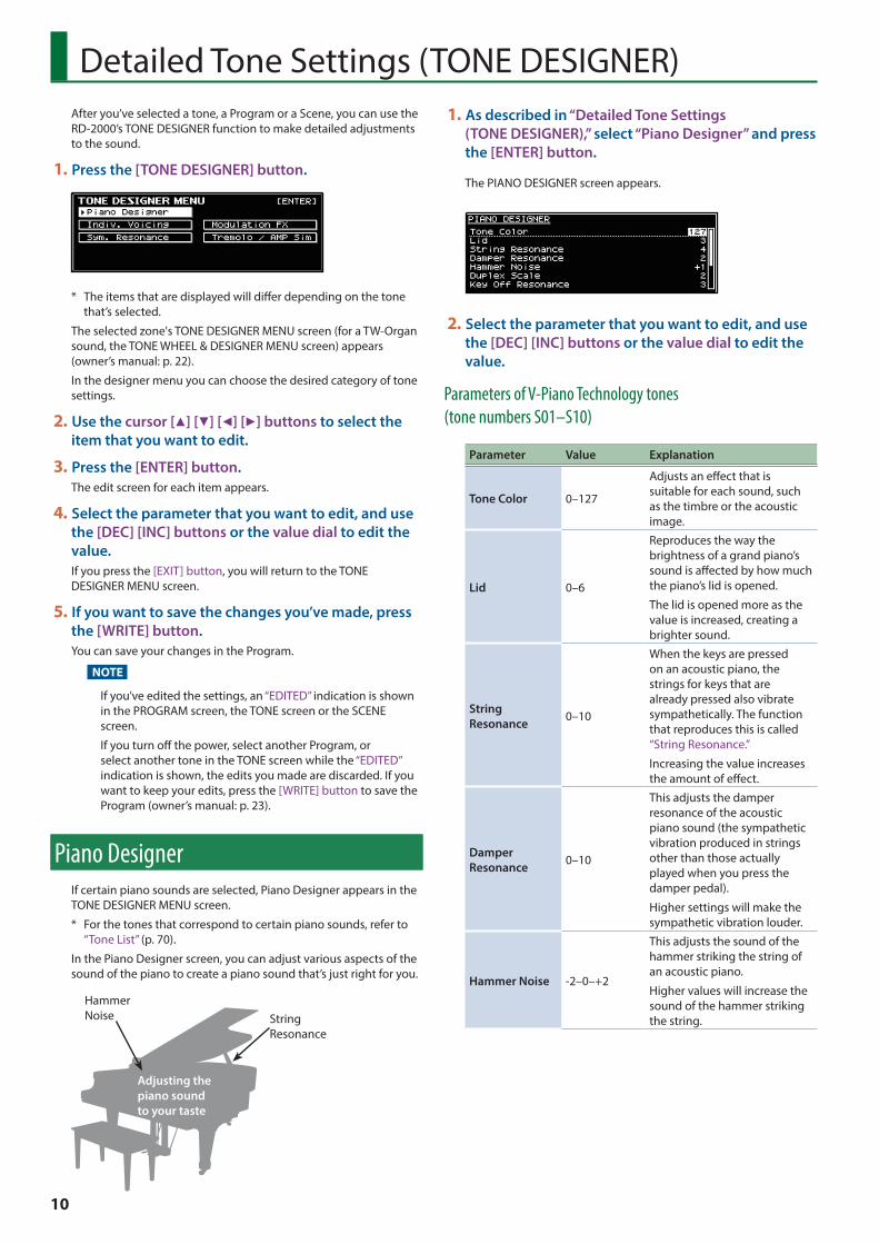
1 Press the [TONE DESIGNER] button.
* The items that are displayed will differ depending on the tone that’s selected.
The selected zone's TONE DESIGNER MENU screen (for a TW-Organ sound, the TONE WHEEL & DESIGNER MENU screen) appears (owner’s manual: p. 22).
In the designer menu you can choose the desired category of tone settings.
2 Use the cursor [H] [I] [K] [J] buttons to select the item that you want to edit.
3 Press the [ENTER] button.The edit screen for each item appears.
4 Select the parameter that you want to edit, and use the [DEC] [INC] buttons or the value dial to edit the value.If you press the [EXIT] button, you will return to the TONE DESIGNER MENU screen.
5 If you want to save the changes you’ve made, press the [WRITE] button.You can save your changes in the Program.
NOTE
If you’ve edited the settings, an “EDITED” indication is shown in the PROGRAM screen, the TONE screen or the SCENE screen.
If you turn off the power, select another Program, or select another tone in the TONE screen while the “EDITED” indication is shown, the edits you made are discarded. If you want to keep your edits, press the [WRITE] button to save the Program (owner’s manual: p. 23).
Piano DesignerIf certain piano sounds are selected, Piano Designer appears in the TONE DESIGNER MENU screen.
* For the tones that correspond to certain piano sounds, refer to “Tone List” (p. 70).
In the Piano Designer screen, you can adjust various aspects of the sound of the piano to create a piano sound that’s just right for you.
String Resonance
Hammer Noise
Adjusting the piano sound to your taste
1 As described in “Detailed Tone Settings (TONE DESIGNER),” select “Piano Designer” and press the [ENTER] button.
The PIANO DESIGNER screen appears.
2 Select the parameter that you want to edit, and use the [DEC] [INC] buttons or the value dial to edit the value.
Parameters of V-Piano Technology tones (tone numbers S01–S10)
Parameter Value Explanation
Tone Color 0–127
Adjusts an effect that is suitable for each sound, such as the timbre or the acoustic image.
Lid 0–6
Reproduces the way the brightness of a grand piano’s sound is affected by how much the piano’s lid is opened.
The lid is opened more as the value is increased, creating a brighter sound.
String Resonance 0–10
When the keys are pressed on an acoustic piano, the strings for keys that are already pressed also vibrate sympathetically. The function that reproduces this is called “String Resonance.”
Increasing the value increases the amount of effect.
Damper Resonance 0–10
This adjusts the damper resonance of the acoustic piano sound (the sympathetic vibration produced in strings other than those actually played when you press the damper pedal).
Higher settings will make the sympathetic vibration louder.
Hammer Noise -2–0–+2
This adjusts the sound of the hammer striking the string of an acoustic piano.
Higher values will increase the sound of the hammer striking the string.
10

Detailed Tone Settings (TONE DESIGNER)
Parameter Value Explanation
Duplex Scale
0–10
Adjusts the sound of the sympathetically vibrating aliquot strings on an acoustic piano.
Higher values increase the volume of the sympathetic vibration.
What is Duplex Scale?
“Duplex Scale” refers to a system that causes sympathetic vibrations in the sections of the string toward the front and toward the back.
It can produce sound that is richer and brighter by adding the string’s higher harmonics.
Because no damper (sound-stopping mechanism) is applied to the front or back sections of the string, the resonating sounds linger even after the sound of the string stops when you release the played key.
Key Off Resonance 0–10
Adjusts resonances such as the key-off sound of an acoustic piano (subtle sounds that are heard when you release a key).
Higher values increase the volume of the resonances.
Cabinet Resonance 0–10
Adjusts the body resonance of the grand piano itself.
Higher values will produce a larger body resonance.
Sound Board Resonator 0–4
When you play a chord, this setting improves the clarity of the individual notes in the chord, creating a more beautiful resonance.
Higher settings produce a clearer resonance.
Damper Noise 0–10
Adjusts the damper noise (the sound that occurs when the strings of an acoustic piano are released by pressing the damper pedal).
Increasing this value increases the sound that is heard when the strings are released.
Key Off Noise 0–10
This adjusts sympathetic vibrations such as an acoustic piano’s key-off sound (the subtle sound that occurs when you release a note).
Higher settings will make the sympathetic vibration louder.
Parameters of SuperNATURAL piano tones (tone numbers 0001–0018, 0028–0039, 0042–0045)
Parameter Value Explanation
Tone Color 0–127
Adjusts an effect that is suitable for each sound, such as the timbre or the acoustic image.
Parameter Value Explanation
Nuance TYPE1, TYPE2, TYPE3
Changes the Tone’s subtle nuances by altering the phase of the left and right sounds.
* This effect is difficult to hear when headphones are used.
Damper Noise 0–127
Adjusts the damper noise (the sound that occurs when the strings of an acoustic piano are released by pressing the damper pedal).
Increasing this value increases the sound that is heard when the strings are released.
Duplex Scale
0–127
Adjusts the sound of the sympathetically vibrating aliquot strings on an acoustic piano.
Higher values increase the volume of the sympathetic vibration.
What is Duplex Scale?
“Duplex Scale” refers to a system that causes sympathetic vibrations in the sections of the string toward the front and toward the back.
It can produce sound that is richer and brighter by adding the string’s higher harmonics.
Because no damper (sound-stopping mechanism) is applied to the front or back sections of the string, the resonating sounds linger even after the sound of the string stops when you release the played key.
String Resonance 0–127
When the keys are pressed on an acoustic piano, the strings for keys that are already pressed also vibrate sympathetically. The function that reproduces this is called “String Resonance.”
Increasing the value increases the amount of effect.
Key Off Resonance 0–127
Adjusts resonances such as the key-off sound of an acoustic piano (subtle sounds that are heard when you release a key).
Higher values increase the volume of the resonances.
Hammer Noise -2–0–+2
Adjusts the sound of the hammers striking the strings of an acoustic piano.
Higher values increase the sound of the hammers striking the strings.
Character -5–0–+5Higher values produce a harder sound; lower values produce a more mellow sound.
11
Detailed Tone Settings (TONE DESIGNER)
Parameter Value Explanation
Sound Lift 0–127
Lets you change the way that the sound responds when you play the keyboard softly. For example, this can be adjusted suitably for solo performance, or to prevent your sound from being buried in the rest of the band.
Increasing this value will allow fairly loud sounds to be produced even when you play with a light touch, so that your performance will not be obscured by the playing of your band.
Changing this value does not affect the way in which the sound responds to velocity.
Tone DesignerIn the Tone Designer screen you can make detailed settings for the sound. The available parameters will depend on the tone that’s selected.
1 As described in “Detailed Tone Settings (TONE DESIGNER)” (p. 10), select “Tone Designer” and press the [ENTER] button.The Tone Designer screen appears.
The parameters will differ depending on the tone that’s selected.
2 Select the parameter that you want to edit, and use the [DEC] [INC] buttons or the value dial to edit the value.
Making Detailed Settings for the E. Piano TonesIf certain electric piano tones are selected, the following parameters will be shown.
* For the tones corresponding to certain electric piano tones, refer to “Tone List” (p. 70).
Parameter Value Explanation
Tone Color 0–127Adjusts an effect that’s suitable for each sound, such as timbre or acoustic image.
Mechanical Key On Noise 0–127
Here you can adjust the loudness of the hammer strike on an electric piano’s sound-producing mechanism, such as the tine or reed.
Higher settings produce a louder hammer strike.
* Depending on the tone that’s selected, this might have no effect.
Parameter Value Explanation
Mechanical Key Off Noise 0–127
Adjusts the key-off sound of the electric piano (the operating sound of the key and hammer when the key is released).
Higher settings produce a louder key-off sound.
* Depending on the tone that’s selected, this might have no effect.
Damper Noise 0–127
Adjusts the damper noise (the noise heard when you press the damper pedal to release the tone bars).
Increasing this value will make the damper noise louder.
* Depending on the tone that’s selected, this might have no effect.
Key Off Resonance 0–127
Adjusts resonances such as the key-off sound (the faint sound heard when you release a key).
Higher values produce a louder key-off sound.
At a setting of 0 there will be no key-off sound at all.
* Depending on the tone that’s selected, this might have no effect.
Hum Noise 0–127
Adjusts the amount of hum and other noise that leaks into the pickups.
Electric pianos were susceptible to various types of noise, and this noise would sometimes be output along with the sounds of the performance. Depending on the effect settings, such noises can produce an authentic, lively atmosphere.
Lowering this value makes the sound clearer; raising this value makes the sound dirtier.
At a setting of 0 there will be no hum at all.
* Depending on the tone that’s selected, this might have no effect.
12

Detailed Tone Settings (TONE DESIGNER)
Parameter Value Explanation
Sound Lift 0–127
Lets you change the way that the sound responds when you play the keyboard softly. For example, this can be adjusted suitably for solo performance, or to prevent your sound from being buried in the rest of the band.
Increasing this value will allow fairly loud sounds to be produced even when you play with a light touch, so that your performance will not be obscured by the playing of your band.
Changing this value does not affect the way in which the sound responds to velocity.
Making Detailed Settings for the CLAV TonesIf certain clav tones are selected, the following parameters appear.
* For details on which clav tones this applies to, refer to “Tone List” (p. 70).
Parameter Value Explanation
Tone Color 0–127Adjusts an effect that’s suitable for each sound, such as timbre or acoustic image.
Pitch Bend Range
0–24 (semitones)
Sets the amount of pitch change to occur when you move the Pitch Bend lever (maximum two octaves).
Key Off Resonance 0–127
Adjusts resonances such as the key-off sound (the faint sound heard when you release a key).
Higher values produce a louder key-off sound.
At a setting of 0 there will be no key-off sound at all.
Hum Noise 0–127
Adjusts the amount of hum and other noise that leaks into the pickups.
Electric clavichords were susceptible to various types of noise, and this noise would sometimes be output along with the sounds of the performance. Depending on the effect settings, such noises can produce an authentic, lively atmosphere.
Lowering this value makes the sound clearer; raising this value makes the sound dirtier.
At a setting of 0 there will be no hum at all.
* Depending on the tone that’s selected, this might have no effect.
Making Detailed Settings for the Other TonesIf you’ve selected a tone other than certain piano, electric piano, or clav tones, the following parameters appears.
Parameter Value Explanation
Tone Color 0–127Adjusts an effect that’s suitable for each sound, such as timbre or acoustic image.
Mono/Poly
Specifies whether the tone is to play polyphonically (POLY) or monophonically (MONO).
The MONO setting is effective when playing a solo instrument tone, such as sax or flute.
Additionally, when this is set to “MONO LEGATO,” you can have monophonic performances be played legato.
Legato is a playing style in which the spaces between notes are smoothed, creating a flowing feel with no borders between the notes. This creates a smooth transition between notes, which is effective when you wish to simulate the hammering-on and pulling-off techniques used by a guitarist.
MONO Only the last-played note will sound.
POLY Two or more notes can be played simultaneously.
MONO LEGATO
Legato is applied to monophonic performances.
Portamento Switch ON, OFF
Portamento is a function that causes the pitch to change smoothly from one note to the next note played.
With the Mono/Poly parameter set to MONO, portamento is especially effective when simulating playing techniques such as violin glissandos.
Portamento Time 0–127
The Portamento Time setting determines the time for the change in pitch when the portamento effect is applied to the sound. Higher settings cause the pitch change to the next note to take more time.
Pitch Bend Range
0–24 (semitone)
Sets the amount of pitch change to occur when you move the Pitch Bend lever (maximum two octaves).
Attack Time Offset -64–+63
The time it takes after the key is pressed for a sound to reach full volume.
Higher values produce a milder attack; lower values produce a sharper attack.
* With some Tones, the effect does not work as intended.
13

Detailed Tone Settings (TONE DESIGNER)
Parameter Value Explanation
Decay Time Offset
-64–+63
This is the time over which the volume decays after the attack is finished.
The time it takes for the volume to fall increases as the value is raised; lowering the value decreases the decay time.
* With some Tones, the effect does not work as intended.
Release Time Offset
The time it takes after the key is released for a sound to become inaudible.
Higher values produce longer decay; set lower values for a clear-cut sound.
* With some Tones, the effect does not work as intended.
Cutoff Offset
Adjusts how much the filter is opened.
Higher values brighten the sound; lower values make the sound seem darker.
* With some Tones, the effect does not work as intended.
Resonance Offset
Emphasizes the overtones in the vicinity of the cutoff frequency, adding character to the sound. Excessively high settings can produce oscillation, causing the sound to distort.
Higher values strengthen the distinctive characteristics of the sound; lower values reduce these characteristics.
* With some Tones, the effect does not work as intended.
Vibrato Rate Offset
Adjusts the vibrato speed (the rate at which the pitch is modulated). The pitch is modulated more rapidly for higher settings, and more slowly with lower settings.
Vibrato Depth Offset
Adjusts the depth of the vibrato effect (the depth at which the pitch is modulated). The pitch is modulated more greatly for higher settings, and less with lower settings.
Vibrato Delay Offset
For each part, this adjusts the time until vibrato (pitch modulation) begins.
Higher settings produce a longer delay time before vibrato begins, while lower settings produce a shorter time.
Editing Individual Keys (Indiv. Voicing)NOTE
5 These settings are available only when editing certain piano tones.
5 For details on the tones to which this applies, refer to “Tone List” (p. 70).
1 In the procedure “Detailed Tone Settings (TONE DESIGNER)” (p. 10), choose “Indiv. Voicing” and press the [ENTER] button.
2 Use the cursor buttons to select a parameter.
3 Press a key to specify the key that you want to edit.
4 Use the [DEC] [INC] buttons or the value dial to edit the values.
TUNINGYou can make fine adjustments to the tuning of each key.
Parameter Value Explanation
Type
OFF, PRST (PRESET), USER
Selects the type of tuning.
PRST (PRESET) is the tuning curve that’s factory-set for the RD-2000.
If you choose USER, you’ll be able to specify the tuning of each key.
Value -50.0–+50.0
Allows for fine adjustments to the tuning of each key in steps of 0.1 cents, over a range of -50.0 to +50.0 cents.
LEVELThis is a fine adjustment to the volume of each key.
Parameter Value Explanation
Type
OFF, PRST (PRESET)*, USER
If you choose USER, you’ll be able to edit the volume of each key.
Value -50–0 Lower values cause the key to be softer than the other keys.
* V-Piano Technology tones only (tone numbers S01–S10)
CHARACTERRelative to the value of the “Character” parameter in Piano Designer, this lets you adjust the offset value for each key.
Parameter Value Explanation
Type
OFF, PRST (PRESET)*, USER
If you choose USER, you’ll be able to edit the Character offset value of each key.
Value -5–0–+5Higher values produce a harder sound; lower values make the tone more mellow.
* V-Piano Technology tones only (tone numbers S01–S10)
14

Detailed Tone Settings (TONE DESIGNER)
MEMO
If you change the value of a key from “OFF” or “PRST,” the Type will automatically change to “USER.”
Adjusting Resonance When the Damper Pedal Is Depressed (Sym. Resonance)
NOTE
These parameters cannot be specified for some tones (V-Piano Technology tones: tone numbers S01–S10) or for zones 5–8.
For details on the tones to which this applies, refer to “Tone List” (p. 70).
You can adjust this resonance when the damper pedal is depressed (Sympathetic Resonance).
On an acoustic piano, holding down the damper pedal will allow the remaining strings to resonate in sympathy with the sounds that you played from the keyboard, adding a rich resonance. This feature reproduces that resonance sound.
Parameter Value Explanation
Switch OFF, ON When set to ON, the effect is applied.
Depth 0–127 Depth of the effect
Damper 0–127Depth to which the damper pedal is pressed (controls the resonant sound)
Pre LPF 16–15000 Hz, BYPASS
Frequency of the filter that cuts the high-frequency content of the input sound (BYPASS: no cut)
Pre HPF BYPASS, 16–15000 Hz
Frequency of the filter that cuts the low-frequency content of the input sound (BYPASS: no cut)
Peaking Freq 16–15000 Hz
Frequency of the filter that boosts/cuts a specific frequency region of the input sound
Peaking Gain -15–+15 dB
Amount of boost/cut produced by the filter at the specified frequency region of the input sound
Peaking Q 0.5, 1.0, 2.0, 4.0, 8.0
Width of the frequency region boosted/cut by the Peaking Gain parameter (larger values make the region narrower)
HF Damp Freq 16–15000 Hz, BYPASS
Frequency at which the high-frequency content of the resonant sound will be cut (BYPASS: no cut)
LF Damp Freq BYPASS, 16–15000 Hz
Frequency at which the low-frequency content of the resonant sound will be cut (BYPASS: no cut)
Level 0–127 Output Level
Damper Offset 0–127Volume of additional slight resonance when the damper pedal is not pressed
Editing the Modulation FX (Modulation FX)
Here you can edit the modulation FX parameters.
NOTE
These parameters cannot be specified for some tones (V-Piano Technology tones: tone numbers S01–S10) or for zones 5–8.
For details on the tones to which this applies, refer to “Tone List” (p. 70).
1 Make the [ZONE EFFECTS] button light.
2 While holding down the [SHIFT] button, operate the MODULATION FX [DEPTH] (or [RATE]) knob.The MODULATION FX screen appears.
3 Select the parameter that you want to edit, and use the [DEC] [INC] buttons or the value dial to edit the value.
Parameter Value Explanation
Type Refer to the effect list (p. 34).
Specifies the type of Modulation FX.
The editable parameters will depend on the effect type that’s selected.
Routing
MOD FX (Modulation FX) 0 TR/AMP (Tremolo/Amp Simulator)
TR/AMP (Tremolo/Amp Simulator) 0 MOD FX (Modulation FX)
Lets you select the routing of the Modulation FX and the Tremolo/Amp Simulator.
By switching the Routing type, you can change the effect that’s applied to the sound.
For example, suppose that you chose Chorus as the MOD FX and chose E.PIANO for TR/AMP; with the MOD FX 0 TR/AMP setting, the chorus sound will be output in monaural, but with the TR/AMP 0 MOD FX setting it will be output in stereo.
Switch OFF, ON Turns the Modulation FX on/off.
MEMO
For details, refer to “Modulation FX Parameters” (p. 34).
15

Detailed Tone Settings (TONE DESIGNER)
Editing Tremolo/Amp Simulator (Tremolo/Amp Simulator)
Here’s how to edit the Tremolo/Amp Simulator parameters.
NOTE
These parameters cannot be specified for some tones (S tones) or for zones 5–8.
For details on the tones to which this applies, refer to “Tone List” (p. 70).
1 Make the [ZONE EFFECTS] button light.
2 While holding down the [SHIFT] button, operate the TREMOLO/AMP SIM [DEPTH] (or [RATE]) knob.The Tremolo/Amp Simulator screen appears.
3 Select the parameter that you want to edit, and use the [DEC] [INC] buttons or the value dial to edit the value.
Parameter Value Explanation
Type
Refer to “Tremolo/Amp simulator types” (p. 16)
Selects the type of Tremolo/Amp Simulator.
The editable parameters will depend on the effect type that’s selected.
Routing
MOD FX (Modulation FX) 0 TR/AMP (Tremolo/Amp Simulator)
TR/AMP (Tremolo/Amp Simulator) 0 MOD FX (Modulation FX)
Lets you select the routing of the Modulation FX and the Tremolo/Amp Simulator.
By switching the Routing type, you can change the effect that’s applied to the sound.
For example, suppose that you chose Chorus as the MOD FX and chose E.PIANO for TR/AMP; with the MOD FX 0 TR/AMP setting the chorus sound will be output in monaural, but with the TR/AMP 0 MOD FX setting it will be output in stereo.
Tremolo/Amp simulator types
Type Explanation
1 NORMALThis is an amp with a flat frequency response. It allows you to add a tremolo effect and distortion.
2 A.PIANO In addition to NORMAL, this reproduces the open/closed state of a grand piano’s lid.
3 E.PIANO
Tremolo types of differing character are available, allowing you to reproduce the character of classic electric pianos when combined with an electric piano sound.
Characteristics of the tremolo types
OLDCASE MONO
Used in conjunction with TINE EP, this simulates an early model of a classic electric piano of the 60s.
OLDCASE STEREO
Used in conjunction with TINE EP, this simulates a classic electric piano sound of the early 70s.
NEWCASE
Used in conjunction with TINE EP, this simulates a classic electric piano sound of the late 70s and early 80s.
DYNO
This model allows you to vary the shape of the tremolo waveform.
Used in conjunction with TINE EP, this simulates an electric piano sound used in many recordings of the early 80s.
WURLY
Used in conjunction with REED E.PIANO, this simulates a classic electric piano sound of the 60s.
4 GUITAR AMP
Simulates playing through a guitar amp.MEMO
Since the [DRIVE] knob faithfully simulates the volume knob of a guitar amp, turning the knob toward the left will also decrease the volume.
5 ROTARY This simulates a rotary effect suitable for organ sounds.
6 MKS-20 Tremolo
This simulates the tremolo effect that was built into the MKS-20.
MEMO
For details, refer to “Tremolo/Amp Simulator Parameters” (p. 61).
16

Detailed Tone Settings (TONE DESIGNER)
Simulating the Creation of Organ TonesThese settings are available only if a TW-Organ (tonewheel organ) tone is selected.
On a tonewheel organ, you can create original sounds by sliding nine harmonic bars (drawbars) forward or backward to change their relative balance. Each bar is assigned a different footage, and this footage determines the pitch of the sound. 8’ is the footage that forms the basic pitch of the sound; this is the center around which you create the tone.
For details, refer to “Creating the Organ Tones” (owner’s manual: p. 22).
17

Using the RD-2000 as a Master Keyboard
What’s MIDI?MIDI (Musical Instrument Digital Interface) is a standard specification that allows musical data to be exchanged between electronic musical instruments and computers.
If devices equipped with MIDI ports are connected via a MIDI cable, you’ll be able to use them in the following ways.
5 Use one MIDI keyboard to play multiple instruments
5 Play multiple MIDI instruments as an ensemble
5 Automatically switch settings as the song progresses
About MIDI ConnectorsThe RD-2000 has the following three types of MIDI connectors. Their functions differ as described below.
MIDI IN connectorPerformance messages from an external MIDI device are received here. These incoming messages may instruct the RD-2000 to play sounds or switch tones.
MIDI OUT connectorMIDI messages are transmitted from these connectors to external MIDI devices. The RD-2000’s MIDI OUT connectors are used for sending the performance data of the controller section.
MIDI THRU connectorMIDI messages received at MIDI IN connectors are re-transmitted without change from this connector to an external MIDI device. Use this in situations such as when you use multiple MIDI devices simultaneously.
MEMO
The RD-2000 lets you switch the function of the MIDI THRU/OUT 2 connector (p. 24).
Adjusting the Volume of Each ZoneIf the INT/EXT select button is lit green, the INT/EXT select button and slider can control the external zone in the same way as the internal zone (owner’s manual: p. 14).
INT/EXT select buttons
You can specify whether MIDI messages including data for your keyboard playing in an external zone is transmitted (or is not transmitted) from the MIDI OUT connector.
For a zone whose INT/EXT select button is lit (green), playing the keyboard will transmit those MIDI messages from MIDI OUT.
For a zone whose button is unlit, playing the keyboard will not transmit MIDI messages.
The INT/EXT select button’s on/off status changes each time you press the button.
Sliders
If the [LEVEL] button is lit, the sliders adjust the volume of each zone.
Selecting the MIDI Connector to Use for Output
The RD-2000 provides a MIDI OUT connector, a MIDI connector whose function can be switched between OUT and THRU, and a USB COMPUTER port.
For each zone you can select the MIDI OUT connector or USB COMPUTER port from which its data is to be transmitted.
1 In the ZONE EDIT screen’s upper line, select the “EXTERNAL” tab.[MENU] button 0 “Program Edit” 0 “Zone Edit”
2 In the “OUT/PC” tab of the lower line, specify the output destination for each zone.
Zone Parameter Settings Explanation
1
OUT (MIDI OUT Port)
ALL,
OUT1 (MIDI OUT 1),
OUT2 (MIDI OUT 2),
USB
The RD-2000’s performance data is transmitted from the selected connector.
2345678
MEMO
If the System parameter MIDI OUT2 Port Mode (p. 24) is set to “THRU,” the performance data from the RD-2000 will not
By connecting an external MIDI device to the MIDI OUT connectors on the RD-2000’s rear panel, you can then control the external MIDI device from the RD-2000.
For each zone, the RD-2000 lets you select either the internal MIDI sound generator (internal: red LED lit) or an external MIDI sound generator (external: green LED lit).
By using an external MIDI sound generator (external), you can control a wide range of settings on the external MIDI sound generator.
You can control internal and external sound generators independently.
If you press the [SHIFT] + [INT/EXT] buttons to make a zone light green, it controls an external MIDI sound generator (external zone). You can press the [SHIFT] + [INT/EXT] button to switch between controlling either the internal zone or the external zone.
You can also make detailed settings for MIDI messages transmitted to external sound modules.
* When Rec Mode (p. 32) is "ON," MIDI messages are not output from external zones.
INT/EXT select buttons
Sliders
18
Using the RD-2000 as a Master Keyboard
be transmitted from the MIDI OUT 2 connector; instead, the performance data received at the MIDI IN connector will be retransmitted without change (MIDI THRU).
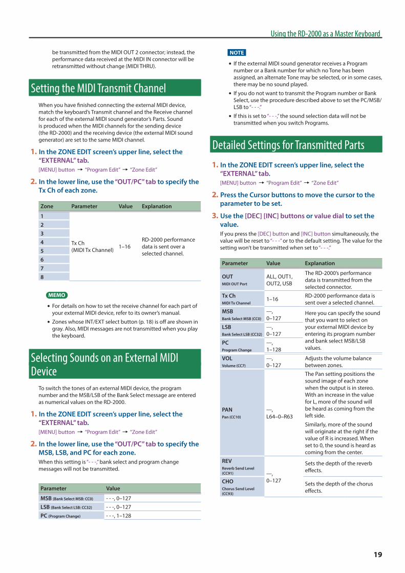
Setting the MIDI Transmit ChannelWhen you have finished connecting the external MIDI device, match the keyboard’s Transmit channel and the Receive channel for each of the external MIDI sound generator’s Parts. Sound is produced when the MIDI channels for the sending device (the RD-2000) and the receiving device (the external MIDI sound generator) are set to the same MIDI channel.
1 In the ZONE EDIT screen’s upper line, select the “EXTERNAL” tab.[MENU] button 0 “Program Edit” 0 “Zone Edit”
2 In the lower line, use the “OUT/PC” tab to specify the Tx Ch of each zone.
Zone Parameter Value Explanation
1
Tx Ch (MIDI Tx Channel) 1–16
RD-2000 performance data is sent over a selected channel.
2345678
MEMO
5 For details on how to set the receive channel for each part of your external MIDI device, refer to its owner’s manual.
5 Zones whose INT/EXT select button (p. 18) is off are shown in gray. Also, MIDI messages are not transmitted when you play the keyboard.
Selecting Sounds on an External MIDI Device
To switch the tones of an external MIDI device, the program number and the MSB/LSB of the Bank Select message are entered as numerical values on the RD-2000.
1 In the ZONE EDIT screen’s upper line, select the “EXTERNAL” tab.[MENU] button 0 “Program Edit” 0 “Zone Edit”
2 In the lower line, use the “OUT/PC” tab to specify the MSB, LSB, and PC for each zone.When this setting is “- - -,” bank select and program change messages will not be transmitted.
Parameter Value
MSB (Bank Select MSB: CC0) - - -, 0–127
LSB (Bank Select LSB: CC32) - - -, 0–127
PC (Program Change) - - -, 1–128
NOTE
5 If the external MIDI sound generator receives a Program number or a Bank number for which no Tone has been assigned, an alternate Tone may be selected, or in some cases, there may be no sound played.
5 If you do not want to transmit the Program number or Bank Select, use the procedure described above to set the PC/MSB/LSB to “- - -.”
5 If this is set to “- - -,” the sound selection data will not be transmitted when you switch Programs.
Detailed Settings for Transmitted Parts1 In the ZONE EDIT screen’s upper line, select the
“EXTERNAL” tab.[MENU] button 0 “Program Edit” 0 “Zone Edit”
2 Press the Cursor buttons to move the cursor to the parameter to be set.
3 Use the [DEC] [INC] buttons or value dial to set the value.If you press the [DEC] button and [INC] button simultaneously, the value will be reset to “- - -” or to the default setting. The value for the setting won’t be transmitted when set to “- - -.”
Parameter Value Explanation
OUTMIDI OUT Port
ALL, OUT1, OUT2, USB
The RD-2000’s performance data is transmitted from the selected connector.
Tx ChMIDI Tx Channel
1–16 RD-2000 performance data is sent over a selected channel.
MSBBank Select MSB (CC0)
---, 0–127
Here you can specify the sound that you want to select on your external MIDI device by entering its program number and bank select MSB/LSB values.
LSBBank Select LSB (CC32)
---, 0–127
PCProgram Change
---, 1–128
VOLVolume (CC7)
---, 0–127
Adjusts the volume balance between zones.
PANPan (CC10)
---, L64–0–R63
The Pan setting positions the sound image of each zone when the output is in stereo. With an increase in the value for L, more of the sound will be heard as coming from the left side.
Similarly, more of the sound will originate at the right if the value of R is increased. When set to 0, the sound is heard as coming from the center.
REVReverb Send Level (CC91) ---,
0–127
Sets the depth of the reverb effects.
CHOChorus Send Level (CC93)
Sets the depth of the chorus effects.
19

Using the RD-2000 as a Master Keyboard
Parameter Value Explanation
Mn/PlyMono (CC126) Poly (CC127)
---, M (Mono), P (Poly)
Specifies whether the tone will play polyphonically (Poly) or monophonically (Mono).
The Mono setting is effective when playing a solo instrument tone such as sax or flute.
TransZone Transpose
-48–+48
You can perform with each zone transposed to a different pitch.
When multiple zones are set to on, you can create a richer sound by setting the two Tones to different octaves. Also, if the Keyboard Mode is set to Split, and you are playing a bass Tone in the lower Part, you can use the Transpose function to play the bass at a lower pitch.
Rng LoKeyboard Range Lower
A0–C8
Set the keyboard range in which each Zone will sound.
This can be used to make notes in different areas of the keyboard play different Tones.
Specify the lower limit (Rng Lo) and upper limit (Rng Up) of the key range being set.
You can also set this by pressing a specific key and then pressing the [ENTER] button.
Rng UpKeyboard Range Upper
Rng LoVelocity Range Lower
1–127
Specify the lower limit (VR.LWR) and upper limit (VR.UPR) of the range in which the tone is played according to how strongly the keys are played (velocity). Make this setting when you want the tone to change depending on the key velocity.
Rng UpVelocity Range Upper
AttackAttack Time Offset (CC73)
---, 0–127
The time it takes after the key is pressed for a sound to reach full volume.
Higher values produce a milder attack; lower values produce a sharper attack.
DecayDecay Time Offset (CC75)
This is the time over which the volume decays after the attack is finished.
The time it takes for the volume to fall increases as the value is raised; lowering the value decreases the decay time.
ReleaseRelease Time Offset (CC72)
The time it takes after the key is released for a sound to become inaudible.
Higher values produce longer decay; set lower values for a clear-cut sound.
Parameter Value Explanation
CutoffCutoff Offset (CC74)
---, 0–127
Adjusts how much the filter is opened.
Higher values brighten the sound; lower values make the sound seem darker.
ResoResonance Offset (CC71)
Emphasizes the overtones in the vicinity of the cutoff frequency, adding character to the sound. Excessively high settings can produce oscillation, causing the sound to distort.
Higher values strengthen the distinctive characteristics of the sound; lower values reduce these characteristics.
POR SwPortamento Switch (CC65)
---, OFF, ON
Turns portamento on/off.
Portamento is a function that causes the pitch to change smoothly from one note to the next note played.
P.TimePortamento Time (CC5)
---, 0–127
The Portamento Time setting determines the time for the change in pitch when the portamento effect is applied to the sound. Higher settings will cause the pitch change to the next note to take more time.
CoarseCoarse Tune
---, -48–+48 Adjusts the pitch in semitone steps (±4 octaves).
FineFine Tune
---, -50–+50Adjusts the pitch in one-cent steps (±50 cents).
1 cent = 1/100th of a semitone
BND RngPitch Bend Range
---, 0–48
Sets the amount of pitch change to occur when you move the Pitch Bend lever (4 octaves).
(RPN: 00H/00H)
MOD DepModulation Depth
---, 0–127
Sets the depth of the effect when the Modulation lever is tilted.
(RPN: 00H/05H)
20

Using the RD-2000 as a Master Keyboard
Parameter Value Explanation
DamperDamper Control Switch
OFF, ON
Damper pedal
Specify whether knobs and other controllers will (ON) or will not (OFF) control an external MIDI device.
FC1FC1 Control Switch
Pedal connected to the FC1 jack
FC2FC2 Control Switch
Pedal connected to the FC2 jack
EXTEXT Pedal Control Switch
Pedal connected to the EXT jack
PCH BNDPitch Bend Control Switch
OFF, ON
Pitch Bend Lever
MOD CTLModulation Control Switch
Modulation Lever
MOD W1MOD Wheel 1 Control Switch
Modulation wheel 1
MOD W2MOD Wheel 2 Control Switch
Modulation wheel 2
A1Assign 1 Control Switch
OFF, ON
ASSIGN [1] knob
A2Assign 2 Control Switch
ASSIGN [2] knob
A3Assign 3 Control Switch
ASSIGN [3] knob
A4Assign 4 Control Switch
ASSIGN [4] knob
A5Assign 5 Control Switch
ASSIGN [5] knob
A6Assign 6 Control Switch
ASSIGN [6] knob
A7Assign 7 Control Switch
ASSIGN [7] knob
A8Assign 8 Control Switch
ASSIGN [8] knob
A9Assign 9 Control Switch
ASSIGN [9] button
CC1User Control Change 1 Number
---, 0–127
You can assign and transmit two different control change messages.
ValueUser Control Change 1 Value
CC2User Control Change 2 Number
ValueUser Control Change 2 Value
21

Setting Parameters (System)Functions that affect the overall operating environment of the RD-2000 are called “system functions.”
[MENU] button 0 Select “System” 0 [ENTER] button0 “SYSTEM” tab
Parameter Value Explanation
Master Tune 415.3–440.0–466.2 [Hz]
Tuning to Other Instruments’ Pitches (Master Tune)For a cleaner ensemble sound while performing with one or more other instruments, ensure that each instrument’s basic pitch is in tune with that of the other instruments. In general, the tuning of an instrument is indicated by the pitch in Hertz (Hz) of the middle “A” note.
Control Destination
Selecting the Target Controlled by a Knob (Control Destination)You can select the target that is controlled by the knobs via ZONE EFFECT, CTRL, and ASSIGN.
SELECT The knobs affect the zones that are selected by the [SELECT] buttons.
PROGRAM The knobs affect the settings specified by ASSIGN SW and FX DEST in ZONE EDIT.
EQ Mode
Retaining the Equalizer Settings Even When the Program Is Switched (EQ Mode)
You can store different equalizer settings (p. 9) for each individual Program (owner’s manual: p. 13).
This setting determines whether or not the Program equalizer settings values are to be changed when Programs are switched.
PROGRAM When you switch Programs, the equalizer settings will also switch.
REMAIN When you switch Programs, the equalizer settings will not change.
Select Button Mode
Retaining the SELECT Button Settings Even When the Program Is Switched (Select Button Mode)
SELECT button settings (owner’s manual: p. 8) can be stored individually for each Program (owner’s manual: p. 13).
You can specify whether the SELECT button settings will or will not change to the functions stored in each Program when you switch a Program.
PROGRAM When you switch Programs, the SELECT button settings will also change.
REMAIN When you switch Programs, the SELECT button settings will not change.
Pedal Mode
Retaining the Pedal Settings Even When the Program Is Switched (Pedal Mode)
Pedal settings (p. 6) can be stored for each Program (owner’s manual: p. 13).
This setting determines whether or not the pedal settings are switched to the values stored in the Program you are switching to.
PROGRAM When you switch Programs, the pedal settings will also change.
REMAIN When you switch Programs, the pedal settings will not change.
Wheel Mode
Retaining the MOD WHEEL 1/2 Settings Even When the Program Is Switched (Wheel Mode)
The settings of the MOD WHEEL 1/2 (p. 7) can be stored for each Program (owner’s manual: p. 13).
This setting determines whether or not the settings of the MOD WHEEL 1/2 are switched to the values stored in the Program you are switching to.
PROGRAM When you switch Programs, the settings of the MOD WHEEL 1/2 will also change.
REMAIN When you switch Programs, the settings of the MOD WHEEL 1/2 will not change.
Detailed Settings for Each Function
22

Detailed Settings for Each Function
Parameter Value Explanation
Assign 1-9 Mode
Retaining the Assign 1–9 Controller Settings Even When the Program Is Switched (Assign 1-9 Mode)
The settings of the Assign 1–9 controllers (p. 7) can be stored individually for each Program (owner’s manual: p. 13).
You can specify whether the Assign 1–9 controller settings stored in the Program will or will not change when you switch Programs.
PROGRAM When you switch Programs, the Assign 1–9 controller settings will also change.
REMAIN When you switch Programs, the Assign 1–9 controller settings will not change.
Delay Mode
Retaining the Delay Settings Even When the Program Is Switched (Delay Mode)
Delay settings (p. 9) can be stored individually for each Program (owner’s manual: p. 13).
You can specify whether the delay settings will or will not change to the values stored in each Program when you select a Program.
PROGRAM When you switch Programs, the delay settings will also change.
REMAIN When you switch Programs, the delay settings will not change.
Reverb Mode
Retaining the Reverb Settings Even When the Program Is Switched (Reverb Mode)
Reverb settings (p. 9) can be stored individually for each Program (owner’s manual: p. 13).
You can specify whether the reverb settings will or will not change to the values stored in each Program when you select a Program.
PROGRAM When you switch Programs, the reverb settings will also change.
REMAIN When you switch Programs, the reverb settings will not change.
Rhythm Mode
Retaining the Rhythm Settings Even When the Program Is Switched (Rhythm Mode)
Rhythm pattern, tempo, and volume (owner’s manual: p. 24) can be stored individually for each Program (owner’s manual: p. 13).
You can specify whether the Rhythm settings will or will not change to the value stored in each Program when you switch a Program.
PROGRAM When you switch Programs, the rhythm settings will also change.
REMAIN When you switch Programs, the rhythm settings will not change.
Key Touch Mode
Retaining the Keyboard Touch Settings Even When the Tone or Program Is Switched (Key Touch Mode)
Key Touch settings (p. 5) can be stored individually for each Program (owner’s manual: p. 13).
You can specify whether the Key Touch settings will or will not change to the values stored in each Program when you switch a Program.
You can also specify whether the tone’s Key Touch settings (valid only for the zone 1) will or will not be applied when you switch tones.
TONE/PROGRAMWhen you switch tones or Programs, the Key Touch settings will also change.
* The setting will not be changed by operations in the Zone Edit screen (p. 4) or when a MIDI message is received to switch tones.
REMAIN When you switch tones or Programs, the Key Touch settings will not change.
23
Detailed Settings for Each Function
Parameter Value Explanation
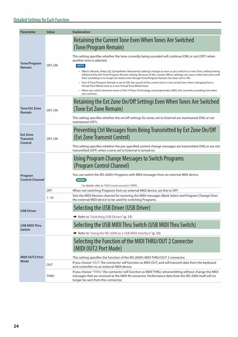
Tone/Program Remain OFF, ON
Retaining the Current Tone Even When Tones Are Switched (Tone/Program Remain)
This setting specifies whether the tone currently being sounded will continue (ON) or not (OFF) when another tone is selected.
NOTE
• Effects (Reverb, Delay, EQ, Sympathetic Resonance) settings change as soon as you switch to a new Tone, without being influenced by the Tone/Program Remain setting. Because of this, certain effects settings can cause notes that were until then sounding to no longer be heard, even though Tone/Program Remain has been set to ON.
• Even if Tone/Program Remain is set to ON, the sound of the current tone is not carried over when changing from a Virtual Tone Wheel tone to a non-Virtual Tone Wheel tone.
• When you switch between tones of the V-Piano Technology sound generator (MD), the currently sounding tone does not continue.
Tone Ext Zone Remain OFF, ON
Retaining the Ext Zone On/Off Settings Even When Tones Are Switched (Tone Ext Zone Remain)
This setting specifies whether the on/off settings for zones set to External are maintained (ON) or not maintained (OFF).
Ext Zone Transmit Control
OFF, ON
Preventing Ctrl Messages from Being Transmitted by Ext Zone On/Off (Ext Zone Transmit Control)
This setting specifies whether the pre-specified control change messages are transmitted (ON) or are not transmitted (OFF) when a zone set to External is turned on.
Program Control Channel
Using Program Change Messages to Switch Programs (Program Control Channel)
You can switch the RD-2000’s Programs with MIDI messages from an external MIDI device.MEMO
For details, refer to “MIDI Implementation” (PDF).
OFF When not switching Programs from an external MIDI device, set this to OFF.
1–16 Sets the MIDI Receive channel for receiving the MIDI messages (Bank Select and Program Change) from the external MIDI device to be used for switching Programs.
USB Driver Selecting the USB Driver (USB Driver)& Refer to “Switching USB Drivers” (p. 33)
USB MIDI Thru Switch
Selecting the USB MIDI Thru Switch (USB MIDI Thru Switch)& Refer to “Using the RD-2000 as a USB MIDI Interface” (p. 33)
MIDI OUT2 Port Mode
Selecting the Function of the MIDI THRU/OUT 2 Connector (MIDI OUT2 Port Mode)
This setting specifies the function of the RD-2000’s MIDI THRU/OUT 2 connector.
OUT If you choose “OUT,” the connector will function as MIDI OUT, and will transmit data from the keyboard and controllers to an external MIDI device.
THRUIf you choose “THRU,” the connector will function as MIDI THRU, retransmitting without change the MIDI messages that are received at the MIDI IN connector. Performance data from the RD-2000 itself will no longer be sent from this connector.
24

Detailed Settings for Each Function
Parameter Value Explanation
Damper Polarity
STANDARD, REVERSE
Switching the Pedal’s Polarity (Damper/FC1/FC2/EXT Pedal Polarity)Switch the polarity of pedals connected to the RD-2000.
This can be set individually for each of the Pedal jacks on the rear panel (FC1, FC2, DAMPER, EXT Pedal).
On some pedals, the electrical signal output by the pedal when it is pressed or released is the opposite of other pedals.
If your pedal has an effect opposite of what you expect, set this parameter to reverse.
If you are using a Roland pedal (that has no polarity switch), set this parameter to STANDARD.
FC1 Polarity
FC2 Polarity
EXT Pedal Polarity
Temperament
Setting the Tuning Method (Temperament/Key)This sets the tuning and keynote (tonic).
Most modern songs are composed and played with the assumption that equal temperament will be used, but when classical music was composed, there were a wide variety of other tuning systems in existence. Playing a composition with its original tuning lets you enjoy the sonorities of the chords that the composer originally intended.
When playing with tuning other than equal temperament, you need to specify the keynote for tuning the song to be performed (that is, the note that corresponds to C for a major key or to A for a minor key).
If you choose an equal temperament, there’s no need to select a keynote.
EQUALEqual Temperament
This tuning divides an octave into 12 equal parts. Every interval produces about the same amount of slight dissonance.
JUST MAJ Just (Major): This scale eliminates dissonance in fifths and thirds. It is unsuited to playing melodies and cannot be transposed, but is capable of beautiful sonorities.
JUST MIN Just (Minor): The scales of the major and minor just intonations are different. You can get the same effect with the minor scale as with the major scale.
PYTHAGOREAN Pythagorean: This scale, devised by the philosopher Pythagoras, eliminates dissonance in fourths and fifths. Dissonance is produced in thirds, but melodies are euphonious.
KIRNBERGER Kirnberger: This scale is a modification of the meantone and just intonations that permits greater freedom in transposition to other keys. Performances are possible in all keys (III).
MEANTONE Meantone: This scale makes some compromises in just intonation, enabling transposition to other keys.
WERCKMEISTER Werckmeister: This is a combination of the meantone and Pythagorean scales. Performances are possible in all keys (first technique, III).
ARABIC Arabic Scale: This scale is suitable for Arabic music.
Temperament Key
C, C#, D, EB, E, F, F#, G, G#, A, BB, B
Sets the keynote.
Clock Out OFF, ONTransmitting Synchronization Messages (Clock Out)
This setting determines whether or not the MIDI messages necessary to synchronize the RD-2000 with external devices are to be transmitted from the MIDI OUT connector.
Hi-Res Velocity Out OFF,ON
Transmitting High-Resolution Velocity Data (Hi-Res Velocity Out )This specifies whether high-resolution velocity data is to be transmitted from the MIDI OUT connector.
Rhythm MIDI Output Port
ALL, OUT1, OUT2, USB
Selecting the MIDI Output Port for Rhythm (Rhythm MIDI Output Port)
This specifies the port from which the rhythm part is to be transmitted.
Rhythm MIDI Out Channel OFF, 1–16
Selecting the MIDI Output Channel for Rhythm (Rhythm MIDI Channel)
This specifies the MIDI channel on which the rhythm part is to be output.
Audio Volume 0–127Adjusting the Playback Volume of Audio Files
This specifies the volume at which audio files play back.
25

Detailed Settings for Each Function
Saving System SettingsChanges you make to the system settings are temporary, and will be lost when you turn off the power.
If you want to keep your changes, you must save the system settings.
1 In the SYSTEM EDIT screen, press the [WRITE] button.A confirmation message appears.
2 Press the [MENU] button.The system settings are saved in the system memory of the RD-2000.
If you decide to cancel, press the [EXIT] button.
Parameters saved in SYSTEM (System parameter) 5 SYSTEM
5 USB AUDIO
5 PART SW
5 COMPRESSOR
USB Audio SettingsHere you can make input/output settings for USB audio.
[MENU] button 0 Select “System” 0 [ENTER] button 0 “USB AUDIO” tab
Parameter Value Explanation
USB Audio Input Switch OFF, ON
Specifies whether to enable USB-AUDIO from an external device.
USB Audio Input Volume 0–127 Specifies the USB audio signal
level from an external device.
USB Audio Output Switch
OFF, ON Specifies whether USB audio is output to an external device.
Parameter Value Explanation
USB Audio Output Volume
0–127 Specifies the USB audio signal level to an external device.
USB Audio Output Assign
MAIN, SUB
Specifies whether the USB audio signal is output from the MAIN jacks or from the SUB jacks.
USB Audio In/Out Select IN, OUT
Selects the USB audio signal that is indicated and adjusted by the slider.
Parameter Value Explanation
Output Mix/Parallel MIX, PARALLEL
Outputting the SUB OUT Output from MAIN OUT (Output Mix/Parallel)This setting specifies whether the output of zones assigned to be output from SUB OUT is sent from MAIN OUT (Mix) or from SUB OUT (Parallel).
LCD Brightness 1–10Adjusting the Brightness of the Display (LCD Brightness)
You can adjust the brightness of the RD-2000’s display.
Auto Off
OFF, 30 [min], 240 [min] (default)
Making the Power Automatically Turn Off After a Time (Auto Off)With the factory settings, the RD-2000 will automatically be switched off 4 hours after you stop playing or operating the unit.
If you don’t need the unit to turn off automatically, set “Auto Off” to the “OFF” setting.
* When turning the unit back on after it has been shut down due to the Auto Off function, always make sure to allow at least ten seconds to pass after the unit has been shut off before you turn the unit back on. If you turn it back on too rapidly, the Auto Off function will not have had enough time to reset itself, and you may not be able to turn on the unit in the normal way.
26

Detailed Settings for Each Function
Selecting the Parts That Will Produce Sound (PART SW)
Here you can specify whether or not performance data is to be received from an external MIDI device.
Sound Generator SectionPart switch
Tone Zone 5 (5ch)
Tone Zone 1 (1ch)
Tone Zone 6 (6ch)
Tone Zone 2 (2ch)
Tone Zone 7 (7ch)
Tone Zone 3 (3ch)
Tone Zone 8 (8ch)
Tone Zone 4 (4ch)
Zone 9 (9ch)Tone
Tone Zone 10 (10ch)
Tone Zone 11 (11ch)
Tone Zone 12 (12ch)
Tone Zone 13 (13ch)
Tone Zone 14 (14ch)
Tone Zone 15 (15ch)
Tone Zone 16 (16ch)
MIDI messages from an external device
[MENU] button 0 Select “System” 0 [ENTER] button 0 “PART SW” tab
Parameter Value Explanation
Part Switch OFF, ON (Part 1–Part 16)
Part Switch settings can be made individually for each part.
NOTE
Tone Color and effects are not available for the parts received on channels 5–16. They may sound differently than the sounds played on channels 1–4.
Making the System Compressor Settings (COMPRESSOR)
This is a stereo compressor (limiter) that is applied to the final output.
With separate settings for the high-frequency range, midrange, and low-frequency range, this reduces inconsistencies in volume levels by compressing the sound when the volume exceeds a preset volume level.
[MENU] button 0 Select “System” 0 [ENTER] button 0 “COMPRESSOR” tab
Parameter Value Explanation
Compressor Switch OFF, ON Turns the compressor on/off.
Parameter Value Explanation
Type Compressor Type
When you change this parameter, the Compressor parameters will be automatically adjusted to the optimal values.
You can make the settings easily by first setting the Compressor Type and then changing only the necessary parameters.
HARD COMP Applies strong compression.
SOFT COMP Applies mild compression.
LOW BOOST Boosts the low end.
MID BOOST Boosts the midrange.
HI BOOST Boosts the high end.
USER The saved settings are written.
Split Freq Low
40, 50, 63, 80, 100, 125, 160, 200, 250, 315, 400, 500, 630, 800 [Hz]
Sets the frequency separating the low-frequency range (LOW) and midrange (MID).
Split Freq High
400, 500, 630, 800, 1000, 1250, 1600, 2000, 2500, 3150, 4000, 5000, 6300, 8000 [Hz]
Sets the frequency separating the high-frequency range (HIGH) and midrange (MID).
Common to High, Mid, and Low
Parameter Value Explanation
Level 0–24 dB (1 dB Step) Output Level
Attack Time 0–100Sets the time it takes until the level is compressed after the input exceeds the Threshold.
Release Time 0–100
Sets the time it takes for the compression to be released after the input falls below the Threshold.
Threshold -60 dB–0 dB (1 dB Step)
Sets the level at which compression begins.
Ratio
1:1.0, 1:1.1, 1:1.2, 1:1.4, 1:1.6, 1:1.8, 1:2.0, 1:2.5, 1:3.2, 1:4.0, 1:5.6, 1:8.0, 1:16, 1:INF
Compression Ratio
INFORMATIONThis shows the RD-2000’s system program version and information about additional sounds.
27

Convenient Functions (Utility)
Saving a Program File (Program File Save)A single, individual file containing a collection of 200 Programs registered to the RD-2000 is called a “Program file.”
This Program file can be saved in the RD-2000’s user memory or on a USB flash drive (sold separately) connected to the USB MEMORY/WLAN ADAPTOR port.
MEMO
The Program file will not save unsaved Programs or system parameter settings.
If you want to save these settings, you must first proceed as described in “Saving the Sound Settings in a Program (Program Write)” (owner’s manual: p. 24) and “Saving System Settings” (p. 26).
1 In the MENU screen, select “Utility” and press the [ENTER] button (owner’s manual: p. 26).
2 Press the cursor [H] buttons to select “Backup Save,” then press the [ENTER] button.
3 Press the cursor [K] [J] buttons to move the cursor to the positions where the characters are to be input.
4 Use the [DEC] [INC] buttons or the value dial to enter the name.Names can consist of up to 16 characters.
Operation Explanation
[SHIFT] + [K] button Delete one character (DELETE)
[SHIFT] + [J] button Insert one space (INSERT)
[H] [I] buttons Switch uppercase/lowercase
NOTE
You can’t save a Program file with a name that starts with a “. (period).” Do not use a “. (period)” at the beginning of the name.
5 Repeat steps 3–4 to input the name.
6 Press the [ENTER] button.The confirmation message appears.
If you do not want to load the Program file, press the [EXIT] button.
7 Press the [MENU] button to save the Program file.The Program file is saved.
NOTE
5 “Processing...” appears in the display while the save is in progress. Be sure never to turn off the power.
5 Do not disconnect the USB flash drive while data is being saved.
MEMO
If a file with the same name has already been saved, the confirmation message “Overwrite OK?” appears. To overwrite the Program file, press the [MENU] button; to save the file under a different name, press the [ENTER] button.
Calling Up Program Files (Backup Load)Here’s how to load a previously saved Program file.
NOTE
The current settings are erased when a Program file is called up. Be sure to save any settings you would like to keep first before calling up a Program file (owner’s manual: p. 26).
1 In the MENU screen, select “Utility” and press the [ENTER] button (owner’s manual: p. 26).
2 Press the cursor [H] [I] buttons to select “Backup Load,” then press the [ENTER] button.
3 Move the cursor to “Backup File” and use the [DEC] [INC] buttons or the value dial to select the file you want to call up.
4 If you want system parameter (p. 26) settings to also be loaded, move the cursor to “Load System Parameters” and choose “YES.”The system parameters are saved in a Program file that has been stored after the [WRITE] button was pressed to save the settings in the RD-2000.
5 Press the [ENTER] button.The confirmation message appears.
If you decide to cancel without loading a Program file, press the [EXIT] button.
6 Press the [MENU] button to load the Program file.The Program file is loaded into the RD-2000.
NOTE
5 Be sure never to turn off the power while the load is in progress.
5 Do not disconnect the USB flash drive while the file is being loaded.
28

Convenient Functions (Utility)
Deleting a Program File (Backup Delete)Here’s how to delete a previously saved Program file.
1 In the MENU screen, select “Utility” and press the [ENTER] button.
2 Use the cursor [H] [I] buttons to select “Backup Delete,” and then press the [ENTER] button.
3 Use the [DEC] [INC] buttons or the value dial to select the Program file that you want to delete; then press the [ENTER] button.The confirmation message appears.
If you decide to cancel without deleting the Program file, press the [EXIT] button.
MEMO
If you choose “ALL,” all Program files will be deleted.
4 Press the [MENU] button to delete the Program file.NOTE
5 Be sure never to turn off the power while the delete is in progress.
5 Do not disconnect the USB flash drive while the file is being deleted.
Formatting Memory (Format)“Formatting” is the operation of deleting all Program files from user memory or initializing a USB flash drive so that it can be used with the RD-2000.
USB flash drive cannot be used with the RD-2000 unless it is formatted suitably for the RD-2000.
Before using a new USB flash drive, you’ll need to format it.
NOTE
When you format the USB flash drive, all data previously saved on that memory will be erased. Before you carry out a format, make sure that the USB flash drive does not contain important data you need to keep.
1 In the MENU screen, select “Utility” and press the [ENTER] button.
2 Press the cursor [H] [I] [K] [J] buttons to select “Format USB Memory” and then press the [ENTER] button.A confirmation message appears.
If you decide to cancel the Format operation, press the [EXIT] button.
3 Carefully read the confirmation message in the screen, and then press the [ENTER] button.
4 Press the [MENU] button to execute the Format operation.
NOTE
5 Never turn off the unit while the screen indicates “Executing...”
5 Never turn off the power or disconnect the USB flash drive while reading or writing is in progress.
Returning to the Factory Settings (Factory Reset)
The settings stored in the RD-2000 can be returned to their factory settings.
1 In the MENU screen, select “Utility” and press the [ENTER] button.
2 Press the cursor [H] [I] [K] [J] buttons to select “Factory Reset” and then press the [ENTER] button.A confirmation message appears.
3 Carefully read the confirmation message in the screen, and then press the [ENTER] button.
4 Press the [MENU] button.Factory reset is executed.
NOTE
Never turn off the power during Factory Reset (while “Executing... Don’t Power OFF” appears in the display).
5 Turn the power of the RD-2000 off, then on again.
29

SCENE UTILITY
Changing the Order of Scenes (Scene Swap)
You can change the order of the scenes to the order that you prefer.
It is convenient to change the order of the scenes to the order in which you use them during a live performance.
1 In the MENU screen, select “Scene Utility” and press the [ENTER] button.
2 Use the cursor [H] [I] [K] [J] buttons to select “Scene Swap,” and then press the [ENTER] button.The SCENE SWAP screen appears.
3 Use the cursor [H][I] buttons and the value dial to select the scene whose order you want to change, and press the [ENTER] button.A confirmation message appears.
4 Press the [MENU] button to execute the swap operation.If you decide to cancel, press the [EXIT] button.
NOTE
Never turn off the power during execution.
Initializing a Scene (Scene Initialize)Here’s how to initialize the settings of the currently selected scene.
NOTE
When you initialize a scene, the currently selected scene disappears.
1 In the MENU screen, select “Scene Utility” and press the [ENTER] button.
2 Use the cursor [H] [I] [K] [J] buttons to select “Scene Initialize,” and then press the [ENTER] button.The SCENE INITIALIZE screen appears.
3 Press the [ENTER] button.A confirmation message appears.
4 Press the [MENU] button to execute initialization.If you decide to cancel, press the [EXIT] button.
NOTE
Never turn off the power during execution.
Adding a Memo to Each Scene (Scene Memo)
You can enter a memo for each recalled scene so that it is shown in the screen (16 characters x 2 lines).
1 In the MENU screen, select “Scene Utility” and press the [ENTER] button.
2 Use the cursor [H] [I] [K] [J] buttons to select “Scene Memo,” and then press the [ENTER] button.The SCENE MEMO screen appears.
3 Use the cursor [K] [J] buttons to move the cursor to the position at which you want to enter a character.
4 Use the [DEC] [INC] buttons or the value dial to enter the characters.
Operation Explanation
[SHIFT] + [K] button Delete one character (DELETE)
[SHIFT] + [J] button Insert one space (INSERT)
[H] [I] button Switch uppercase/lowercase
5 Repeat steps 3–4 to input the memo.
6 Press the [ENTER] button.A confirmation message appears.
If you decide to cancel, press the [EXIT] button.
7 Press the [MENU] button.The memo is saved.
30
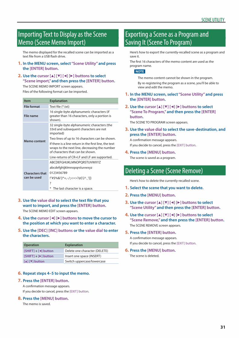
SCENE UTILITY
Importing Text to Display as the Scene Memo (Scene Memo Import)
The memo displayed for the recalled scene can be imported as a text file from a USB flash drive.
1 In the MENU screen, select “Scene Utility” and press the [ENTER] button.
2 Use the cursor [H] [I] [K] [J] buttons to select “Scene import,” and then press the [ENTER] button.The SCENE MEMO IMPORT screen appears.
Files of the following format can be imported.
Item Explanation
File format Text file (*.txt)
File name16 single-byte alphanumeric characters (if greater than 16 characters, only a portion is shown).
Memo content
32 single-byte alphanumeric characters (the 33rd and subsequent characters are not imported)
Two lines of up to 16 characters can be shown.
If there is a line-return in the first line, the text wraps to the next line, decreasing the number of characters that can be shown.
Line-returns of CR+LF and LF are supported.
Characters that can be used
ABCDEFGHIJKLMNOPQRSTUVWXYZ
abcdefghijklmnopqrstuvwxyz
0123456789
!”#$%&’()*+,-./:;<=>?@[\]^_’{|}
?
* The last character is a space.
3 Use the value dial to select the text file that you want to import, and press the [ENTER] button.The SCENE MEMO EDIT screen appears.
4 Use the cursor [K] [J] buttons to move the cursor to the position at which you want to enter a character.
5 Use the [DEC] [INC] buttons or the value dial to enter the characters.
Operation Explanation
[SHIFT] + [K] button Delete one character (DELETE)
[SHIFT] + [J] button Insert one space (INSERT)
[H] [I] button Switch uppercase/lowercase
6 Repeat steps 4–5 to input the memo.
7 Press the [ENTER] button.A confirmation message appears.
If you decide to cancel, press the [EXIT] button.
8 Press the [MENU] button.The memo is saved.
Exporting a Scene as a Program and Saving It (Scene To Program)
Here’s how to export the currently-recalled scene as a program and save it.
The first 16 characters of the memo content are used as the program name.
NOTE
The memo content cannot be shown in the program.
By re-registering the program as a scene, you’ll be able to view and edit the memo.
1 In the MENU screen, select “Scene Utility” and press the [ENTER] button.
2 Use the cursor [H] [I] [K] [J] buttons to select “Scene To Program,” and then press the [ENTER] button.The SCENE TO PROGRAM screen appears.
3 Use the value dial to select the save-destination, and press the [ENTER] button.A confirmation message appears.
If you decide to cancel, press the [EXIT] button.
4 Press the [MENU] button.The scene is saved as a program.
Deleting a Scene (Scene Remove)Here’s how to delete the currently-recalled scene.
1 Select the scene that you want to delete.
2 Press the [MENU] button.
3 Use the cursor [H] [I] [K] [J] buttons to select “Scene Utility” and then press the [ENTER] button.
4 Use the cursor [H] [I] [K] [J] buttons to select “Scene Remove,” and then press the [ENTER] button.The SCENE REMOVE screen appears.
5 Press the [ENTER] button.A confirmation message appears.
If you decide to cancel, press the [EXIT] button.
6 Press the [MENU] button.The scene is deleted.
31
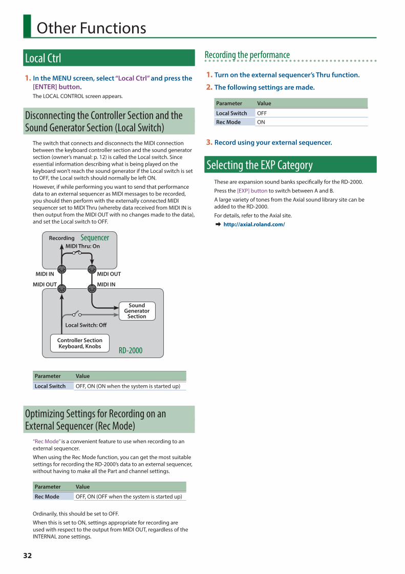
Other Functions
Local Ctrl1 In the MENU screen, select “Local Ctrl” and press the
[ENTER] button.The LOCAL CONTROL screen appears.
Disconnecting the Controller Section and the Sound Generator Section (Local Switch)
The switch that connects and disconnects the MIDI connection between the keyboard controller section and the sound generator section (owner’s manual: p. 12) is called the Local switch. Since essential information describing what is being played on the keyboard won’t reach the sound generator if the Local switch is set to OFF, the Local switch should normally be left ON.
However, if while performing you want to send that performance data to an external sequencer as MIDI messages to be recorded, you should then perform with the externally connected MIDI sequencer set to MIDI Thru (whereby data received from MIDI IN is then output from the MIDI OUT with no changes made to the data), and set the Local switch to OFF.
RecordingMIDI Thru: On
Controller SectionKeyboard, Knobs
Sound Generator
SectionLocal Switch: Off
RD-2000
Sequencer
MIDI IN
MIDI INMIDI OUT
MIDI OUT
Parameter Value
Local Switch OFF, ON (ON when the system is started up)
Optimizing Settings for Recording on an External Sequencer (Rec Mode)
“Rec Mode” is a convenient feature to use when recording to an external sequencer.
When using the Rec Mode function, you can get the most suitable settings for recording the RD-2000’s data to an external sequencer, without having to make all the Part and channel settings.
Parameter Value
Rec Mode OFF, ON (OFF when the system is started up)
Ordinarily, this should be set to OFF.
When this is set to ON, settings appropriate for recording are used with respect to the output from MIDI OUT, regardless of the INTERNAL zone settings.
Recording the performance
1 Turn on the external sequencer’s Thru function.
2 The following settings are made.
Parameter Value
Local Switch OFF
Rec Mode ON
3 Record using your external sequencer.
Selecting the EXP CategoryThese are expansion sound banks specifically for the RD-2000.
Press the [EXP] button to switch between A and B.
A large variety of tones from the Axial sound library site can be added to the RD-2000.
For details, refer to the Axial site.& http://axial roland com/
32

Connecting to a Computer via the USB COMPUTER Port
If you use a USB cable (sold separately) to connect the USB COMPUTER port located on the RD-2000’s rear panel to the USB port of your computer, you’ll be able to do the following things.
5 Use the RD-2000 to play SMF music files played back by MIDI compatible software.
5 By transferring MIDI data between the RD-2000 and your sequencer software, you’ll be able to enjoy a wide range of possibilities for music production and editing.
NOTE
Refer to the Roland website for system requirements.
Roland website:
http://www roland com/Depending on the type of computer you’re using, this may not operate correctly.
For details on supported operating systems, refer to the Roland website.
You can download the original driver from the Roland website.
Specify the USB driver you want to use, and then install the driver. For details, refer to “Switching USB Drivers” (p. 33).
Caution 5 A USB cable is not included. If you need to obtain one, ask the dealer where you purchased the RD-2000.
5 Switch on power to the RD-2000 before you start up the MIDI application on your computer. Don’t turn the RD-2000 on/off while your MIDI application is running.
Switching USB DriversThe USB driver to be used when a computer is connected to the USB COMPUTER port is determined as follows:
1 Press the [MENU] button.
2 Press the cursor [H] [I] buttons to select “System,” and then press the [ENTER] button.
3 Press the cursor [H] [I] buttons to move the cursor to “USB Driver.”
4 Use the [DEC] [INC] buttons or the value dial to select the USB driver you want to use.Parameter Value Explanation
USB Driver
VENDORChoose this if you’re using the USB driver downloaded from the Roland website.
GENERICChoose this if you’re using the default USB driver that came with your computer.
5 Press the [WRITE] button.
6 Press the [MENU] button.
7 Turn the RD-2000 off, then on again.
Using the RD-2000 as a USB MIDI InterfaceIf the RD-2000 is connected to your computer, performance data from a MIDI device connected to the RD-2000’s MIDI IN connector can be sent to your computer.
Parameter Value Explanation
USB MIDI Thru Switch
OFF
Performance data from the device connected to the RD-2000’s MIDI IN connector will not be sent to your computer.
ON
Performance data from the device connected to the RD-2000’s MIDI IN connector will be sent to your computer.
What is the USB MIDI driver?The USB MIDI Driver is a software which passes data between the RD-2000 and the application (sequencer software, etc.) that is running on the USB-connected computer.
The USB MIDI Driver sends data from the application to the RD-2000, and passes data from the RD-2000 to the application.
Application
USB Driver
Computer
USB port
RD-2000
USB cable
USB COMPUTER port
Connecting to Your Computer
33
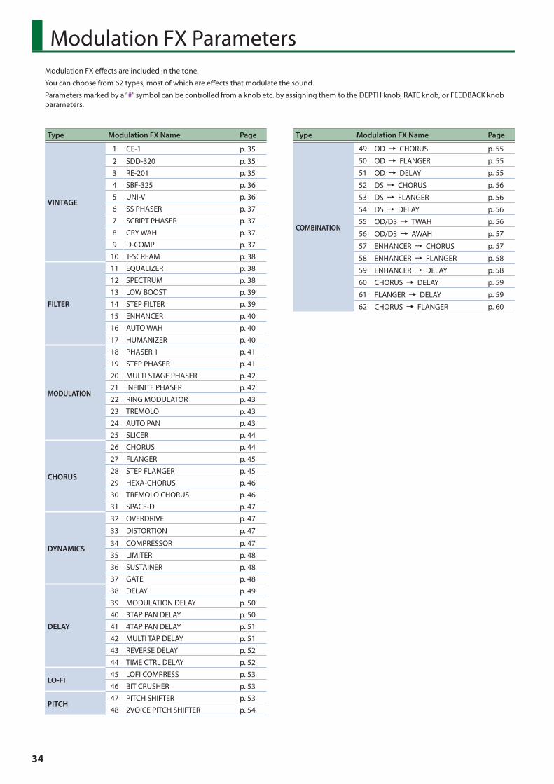
34
Modulation FX Parameters
Type Modulation FX Name Page
VINTAGE
1 CE-1 p. 35
2 SDD-320 p. 35
3 RE-201 p. 35
4 SBF-325 p. 36
5 UNI-V p. 36
6 SS PHASER p. 37
7 SCRIPT PHASER p. 37
8 CRY WAH p. 37
9 D-COMP p. 37
10 T-SCREAM p. 38
FILTER
11 EQUALIZER p. 38
12 SPECTRUM p. 38
13 LOW BOOST p. 39
14 STEP FILTER p. 39
15 ENHANCER p. 40
16 AUTO WAH p. 40
17 HUMANIZER p. 40
MODULATION
18 PHASER 1 p. 41
19 STEP PHASER p. 41
20 MULTI STAGE PHASER p. 42
21 INFINITE PHASER p. 42
22 RING MODULATOR p. 43
23 TREMOLO p. 43
24 AUTO PAN p. 43
25 SLICER p. 44
CHORUS
26 CHORUS p. 44
27 FLANGER p. 45
28 STEP FLANGER p. 45
29 HEXA-CHORUS p. 46
30 TREMOLO CHORUS p. 46
31 SPACE-D p. 47
DYNAMICS
32 OVERDRIVE p. 47
33 DISTORTION p. 47
34 COMPRESSOR p. 47
35 LIMITER p. 48
36 SUSTAINER p. 48
37 GATE p. 48
DELAY
38 DELAY p. 49
39 MODULATION DELAY p. 50
40 3TAP PAN DELAY p. 50
41 4TAP PAN DELAY p. 51
42 MULTI TAP DELAY p. 51
43 REVERSE DELAY p. 52
44 TIME CTRL DELAY p. 52
LO-FI45 LOFI COMPRESS p. 53
46 BIT CRUSHER p. 53
PITCH47 PITCH SHIFTER p. 53
48 2VOICE PITCH SHIFTER p. 54
Type Modulation FX Name Page
COMBINATION
49 OD 0 CHORUS p. 55
50 OD 0 FLANGER p. 55
51 OD 0 DELAY p. 55
52 DS 0 CHORUS p. 56
53 DS 0 FLANGER p. 56
54 DS 0 DELAY p. 56
55 OD/DS 0 TWAH p. 56
56 OD/DS 0 AWAH p. 57
57 ENHANCER 0 CHORUS p. 57
58 ENHANCER 0 FLANGER p. 58
59 ENHANCER 0 DELAY p. 58
60 CHORUS 0 DELAY p. 59
61 FLANGER 0 DELAY p. 59
62 CHORUS 0 FLANGER p. 60
Modulation FX effects are included in the tone.
You can choose from 62 types, most of which are effects that modulate the sound.
Parameters marked by a “#” symbol can be controlled from a knob etc. by assigning them to the DEPTH knob, RATE knob, or FEEDBACK knob parameters.
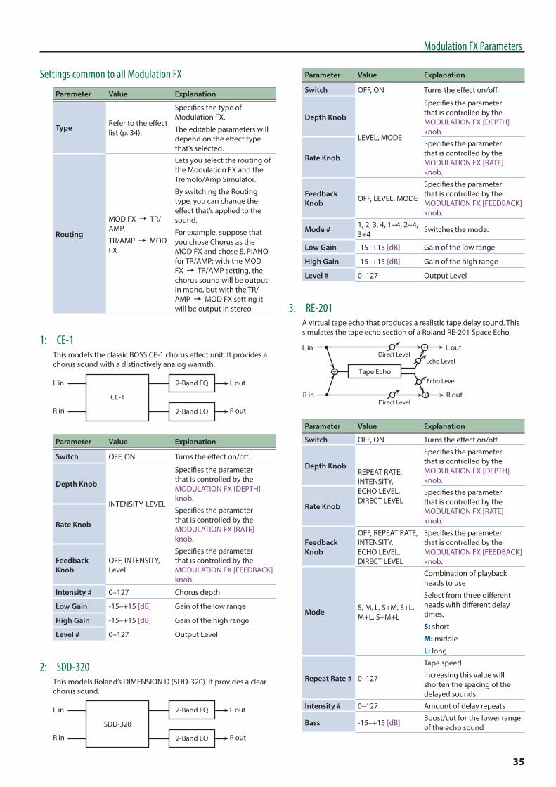
35
Modulation FX Parameters
Settings common to all Modulation FX
Parameter Value Explanation
Type Refer to the effect list (p. 34).
Specifies the type of Modulation FX.
The editable parameters will depend on the effect type that’s selected.
Routing
MOD FX 0 TR/AMP,
TR/AMP 0 MOD FX
Lets you select the routing of the Modulation FX and the Tremolo/Amp Simulator.
By switching the Routing type, you can change the effect that’s applied to the sound.
For example, suppose that you chose Chorus as the MOD FX and chose E. PIANO for TR/AMP; with the MOD FX 0 TR/AMP setting, the chorus sound will be output in mono, but with the TR/AMP 0 MOD FX setting it will be output in stereo.
1: CE-1This models the classic BOSS CE-1 chorus effect unit. It provides a chorus sound with a distinctively analog warmth.
L in
R in
L out
R out
CE-1
2-Band EQ
2-Band EQ
Parameter Value Explanation
Switch OFF, ON Turns the effect on/off.
Depth Knob
INTENSITY, LEVEL
Specifies the parameter that is controlled by the MODULATION FX [DEPTH] knob.
Rate Knob
Specifies the parameter that is controlled by the MODULATION FX [RATE] knob.
Feedback Knob
OFF, INTENSITY, Level
Specifies the parameter that is controlled by the MODULATION FX [FEEDBACK] knob.
Intensity # 0–127 Chorus depth
Low Gain -15–+15 [dB] Gain of the low range
High Gain -15–+15 [dB] Gain of the high range
Level # 0–127 Output Level
2: SDD-320This models Roland’s DIMENSION D (SDD-320). It provides a clear chorus sound.
L in
R in
L out
R out
SDD-320
2-Band EQ
2-Band EQ
Parameter Value Explanation
Switch OFF, ON Turns the effect on/off.
Depth Knob
LEVEL, MODE
Specifies the parameter that is controlled by the MODULATION FX [DEPTH] knob.
Rate Knob
Specifies the parameter that is controlled by the MODULATION FX [RATE] knob.
Feedback Knob OFF, LEVEL, MODE
Specifies the parameter that is controlled by the MODULATION FX [FEEDBACK] knob.
Mode # 1, 2, 3, 4, 1+4, 2+4, 3+4 Switches the mode.
Low Gain -15–+15 [dB] Gain of the low range
High Gain -15–+15 [dB] Gain of the high range
Level # 0–127 Output Level
3: RE-201A virtual tape echo that produces a realistic tape delay sound. This simulates the tape echo section of a Roland RE-201 Space Echo.
Echo Level
Echo Level
L in
R in
L out
R out
Tape Echo
Direct Level
Direct Level
Parameter Value Explanation
Switch OFF, ON Turns the effect on/off.
Depth KnobREPEAT RATE, INTENSITY, ECHO LEVEL, DIRECT LEVEL
Specifies the parameter that is controlled by the MODULATION FX [DEPTH] knob.
Rate Knob
Specifies the parameter that is controlled by the MODULATION FX [RATE] knob.
Feedback Knob
OFF, REPEAT RATE, INTENSITY, ECHO LEVEL, DIRECT LEVEL
Specifies the parameter that is controlled by the MODULATION FX [FEEDBACK] knob.
Mode S, M, L, S+M, S+L, M+L, S+M+L
Combination of playback heads to use
Select from three different heads with different delay times.
S: short
M: middle
L: long
Repeat Rate # 0–127
Tape speed
Increasing this value will shorten the spacing of the delayed sounds.
Intensity # 0–127 Amount of delay repeats
Bass -15–+15 [dB] Boost/cut for the lower range of the echo sound

36
Modulation FX Parameters
Parameter Value Explanation
Treble -15–+15 [dB] Boost/cut for the upper range of the echo sound
Head S PanL64–63R
Independent panning for the short, middle, and long playback heads
Head M PanHead L Pan
Tape Distortion 0–5
Amount of tape-dependent distortion to be added
This simulates the slight tonal changes that can be detected by signal-analysis equipment. Increasing this value will increase the distortion.
W/F Rate 0–127
Speed of wow/flutter (complex variation in pitch caused by tape wear and rotational irregularity)
W/F Depth 0–127 Depth of wow/flutter
Echo Level # 0–127 Volume of the echo sound
Direct Level # 0–127 Volume of the original sound
Level 0–127 Output Level
4: SBF-325This effect reproduces Roland’s SBF-325 analog flanger. It provides three types of flanging effect (which adds a metallic resonance to the original sound) and a chorus-type effect.
L
RSBF-325
Parameter Value Explanation
Switch OFF, ON Turns the effect on/off.
Depth Knob
RATE, DEPTH, FEEDBACK
Specifies the parameter that is controlled by the MODULATION FX [DEPTH] knob.
Rate Knob
Specifies the parameter that is controlled by the MODULATION FX [RATE] knob.
Feedback Knob
Specifies the parameter that is controlled by the MODULATION FX [FEEDBACK] knob.
Mode FL1, FL2, FL3, CHO
Types of flanging effect
FL1: A typical mono flanger
FL2: A stereo flanger that preserves the stereo positioning of the original sound
FL3: A cross-mix flanger that produces a more intense effect
CHO: A chorus effect
Rate (sync sw) OFF, ON
If this is ON, the rate is synchronized to the tempo of the rhythm (owner’s manual: p. 24).
Rate (Hz) # 0.02–5.00 [Hz] Rate at which the flanger sound is modulatedRate (note) # note (p. 60)
Parameter Value Explanation
Depth # 0–127 Depth to which the flanger sound is modulated
Manual 0–127 Center frequency at which the flanger effect is applied
Feedback # 0–127
Amount by which the flanging effect is boosted
* If Mode is CHO, this setting is ignored.
CH-R Mode Phase
NORM, INV
Phase of the right channel modulation: Typically, you will leave this at Normal (NORM). If you specify Inverted (INV), the modulation (upward/downward movement) of the right channel is inverted.
CH-L PhasePhase when mixing the flanging sound with the original sound
NORM: normal phase
INV: inverse phaseCH-R Phase
Level 0–127 Output Level
5: UNI-VThis models a Uni-Vibe.
This effect is similar to a phaser, but produces a distinctive modulation that cannot be obtained from a normal phaser.
UNI-V 2-Band EQ
L in
R in
L out
R out
Parameter Value Explanation
Switch OFF, ON Turns the effect on/off.
Depth Knob
RATE, DEPTH, LEVEL
Specifies the parameter that is controlled by the MODULATION FX [DEPTH] knob.
Rate Knob
Specifies the parameter that is controlled by the MODULATION FX [RATE] knob.
Feedback Knob
Specifies the parameter that is controlled by the MODULATION FX [FEEDBACK] knob.
Rate # 0–100 Adjusts the rate of the UNI-V effect.
Depth # 0–100 Adjusts the depth of the UNI-V effect.
Low Gain -15–+15 [dB] Gain of the low range
High Gain -15–+15 [dB] Gain of the high range
Level # 0–127 Output Level

37
Modulation FX Parameters
6: SS PHASERThis simulates an analog phaser of the past.
It is particularly suitable for electric piano.
L in
R in
L out
R out
Phaser
2-Band EQ
2-Band EQ
Phaser
Parameter Value Explanation
Switch OFF, ON Turns the effect on/off.
Depth Knob
RATE, COLOR
Specifies the parameter that is controlled by the MODULATION FX [DEPTH] knob.
Rate Knob
Specifies the parameter that is controlled by the MODULATION FX [RATE] knob.
Feedback Knob OFF, RATE, COLOR
Specifies the parameter that is controlled by the MODULATION FX [FEEDBACK] knob.
Rate # 0–100 Frequency of modulation
Color # 1, 2 Modulation character
Low Gain -15–+15 [dB] Gain of the low range
High Gain -15–+15 [dB] Gain of the high range
Level 0–127 Output Level
7: SCRIPT PHASERThis simulates a different analog phaser than SS PHASER.
It is particularly suitable for electric piano.
L in
R in
L out
R out
Phaser
2-Band EQ
2-Band EQ
Phaser
Parameter Value Explanation
Switch OFF, ON Turns the effect on/off.
Depth Knob
SPEED, DEPTH
Specifies the parameter that is controlled by the MODULATION FX [DEPTH] knob.
Rate Knob
Specifies the parameter that is controlled by the MODULATION FX [RATE] knob.
Feedback Knob
OFF, SPEED, DEPTH
Specifies the parameter that is controlled by the MODULATION FX [FEEDBACK] knob.
Speed # 0–100 Frequency of modulation
Depth # 0–127 Modulation character
Low Gain -15–+15 [dB] Gain of the low range
High Gain -15–+15 [dB] Gain of the high range
Level 0–127 Output Level
8: CRY WAHThis models the sound of the CRY BABY wah pedal popular in the ‘70s.
E�ect Level
Direct LevelL in
R in
L out
R out
2-BandEQ
WAH
Parameter Value Explanation
Switch OFF, ON Turns the effect on/off.
Depth Knob
PEDAL POSITION, EFFECT LEVEL, DIRECT LEVEL
Specifies the parameter that is controlled by the MODULATION FX [DEPTH] knob.
Rate Knob
Specifies the parameter that is controlled by the MODULATION FX [RATE] knob.
Feedback Knob
Specifies the parameter that is controlled by the MODULATION FX [FEEDBACK] knob.
Pedal Position # 0–100
Adjusts the position of the wah pedal.
* This parameter can also be assigned to a pedal etc. and controlled.
Pedal Min 0–100Selects the tone produced when the heel of the EXP Pedal is depressed.
Pedal Max 0–100Selects the tone produced when the toe of the EXP Pedal is depressed.
Low Gain -15–+15 [dB] Adjusts the low frequency range tone.
High Gain -15–+15 [dB] Adjusts the high frequency range tone.
Effect Level # 0–127 Adjusts the volume of the effect sound.
Direct Level # 0–127 Adjusts the volume of the direct sound.
9: D-COMPThis models a MXR DynaComp.
Compressor Tone
L in
R in
L out
R out
Parameter Value Explanation
Switch OFF, ON Turns the effect on/off.

38
Modulation FX Parameters
Parameter Value Explanation
Depth Knob
SENS, RELEASE, LEVEL
Specifies the parameter that is controlled by the MODULATION FX [DEPTH] knob.
Rate Knob
Specifies the parameter that is controlled by the MODULATION FX [RATE] knob.
Feedback Knob
Specifies the parameter that is controlled by the MODULATION FX [FEEDBACK] knob.
Sens # 0–100 This controls the input sensitivity.
Release # 0–100 Adjusts the release time.
Tone -50–+50 Adjusts the tone.
Level # 0–127 Output Level
10: T-SCREAMThis models the analog overdrive of the past.
It adds a nice amount of overtones without dirtying the sound.
L in
R in
L out
R out
Overdrive
Tone
Tone
Overdrive
Parameter Value Explanation
Switch OFF, ON Turns the effect on/off.
Depth Knob
DISTORTION, TONE
Specifies the parameter that is controlled by the MODULATION FX [DEPTH] knob.
Rate Knob
Specifies the parameter that is controlled by the MODULATION FX [RATE] knob.
Feedback Knob
OFF, DISTORTION, TONE
Specifies the parameter that is controlled by the MODULATION FX [FEEDBACK] knob.
Distortion # 0–127Degree of distortion
Also changes the volume.
Tone # 0–127 Sound quality of the Overdrive effect
Level 0–127 Output Level
11: EQUALIZERThis is a four-band stereo equalizer (low, mid x 2, high).
L in
R in
L out
R out
4-Band EQ
4-Band EQ
Parameter Value Explanation
Switch OFF, ON Turns the effect on/off.
Parameter Value Explanation
Depth KnobLOW GAIN, HIGH GAIN, LEVEL
Specifies the parameter that is controlled by the MODULATION FX [DEPTH] knob.
Rate Knob
Specifies the parameter that is controlled by the MODULATION FX [RATE] knob.
Feedback Knob
OFF, LOW GAIN, HIGH GAIN, LEVEL
Specifies the parameter that is controlled by the MODULATION FX [FEEDBACK] knob.
Low Freq 20–400 [Hz] Frequency of the low range
Low Gain # -15–+15 [dB] Gain of the low range
Mid1 Freq 200–8000 [Hz] Frequency of the middle range 1
Mid1 Gain -15–+15 [dB] Gain of the middle range 1
Mid1 Q 0.5, 1.0, 2.0, 4.0, 8.0
Width of the middle range 1
Set a higher value to narrow the range to be affected.
Mid2 Freq 200–8000 [Hz] Frequency of the middle range 2
Mid2 Gain -15–+15 [dB] Gain of the middle range 2
Mid2 Q 0.5, 1.0, 2.0, 4.0, 8.0
Width of the middle range 2
Set a higher value to narrow the range to be affected.
High Freq 2000–16000 [Hz] Frequency of the high range
High Gain # -15–+15 [dB] Gain of the high range
Level # 0–127 Output Level
12: SPECTRUMThis is a stereo spectrum. Spectrum is a type of filter which modifies the timbre by boosting or cutting the level at specific frequencies.
L in
R in
L out
R out
Spectrum
Spectrum
Parameter Value Explanation
Switch OFF, ON Turns the effect on/off.
Depth KnobBAND1, BAND3, LEVEL
Specifies the parameter that is controlled by the MODULATION FX [DEPTH] knob.
Rate Knob
Specifies the parameter that is controlled by the MODULATION FX [RATE] knob.
Feedback Knob
OFF, BAND1, BAND3, LEVEL
Specifies the parameter that is controlled by the MODULATION FX [FEEDBACK] knob.
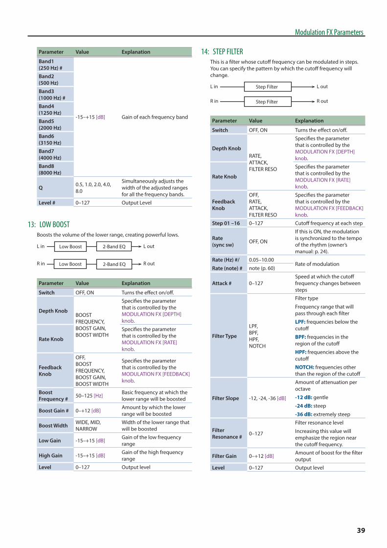
39
Modulation FX Parameters
Parameter Value Explanation
Band1 (250 Hz) #
-15–+15 [dB] Gain of each frequency band
Band2 (500 Hz)Band3 (1000 Hz) #Band4 (1250 Hz)Band5 (2000 Hz)Band6 (3150 Hz)Band7 (4000 Hz)Band8 (8000 Hz)
Q 0.5, 1.0, 2.0, 4.0, 8.0
Simultaneously adjusts the width of the adjusted ranges for all the frequency bands.
Level # 0–127 Output Level
13: LOW BOOSTBoosts the volume of the lower range, creating powerful lows.
L in
R in
L out
R out
Low Boost
2-Band EQ
2-Band EQ
Low Boost
Parameter Value Explanation
Switch OFF, ON Turns the effect on/off.
Depth KnobBOOST FREQUENCY, BOOST GAIN, BOOST WIDTH
Specifies the parameter that is controlled by the MODULATION FX [DEPTH] knob.
Rate Knob
Specifies the parameter that is controlled by the MODULATION FX [RATE] knob.
Feedback Knob
OFF, BOOST FREQUENCY, BOOST GAIN, BOOST WIDTH
Specifies the parameter that is controlled by the MODULATION FX [FEEDBACK] knob.
Boost Frequency # 50–125 [Hz] Basic frequency at which the
lower range will be boosted
Boost Gain # 0–+12 [dB] Amount by which the lower range will be boosted
Boost Width WIDE, MID, NARROW
Width of the lower range that will be boosted
Low Gain -15–+15 [dB] Gain of the low frequency range
High Gain -15–+15 [dB] Gain of the high frequency range
Level 0–127 Output level
14: STEP FILTERThis is a filter whose cutoff frequency can be modulated in steps. You can specify the pattern by which the cutoff frequency will change.
L in
R in
L out
R out
Step Filter
Step Filter
Parameter Value Explanation
Switch OFF, ON Turns the effect on/off.
Depth KnobRATE, ATTACK, FILTER RESO
Specifies the parameter that is controlled by the MODULATION FX [DEPTH] knob.
Rate Knob
Specifies the parameter that is controlled by the MODULATION FX [RATE] knob.
Feedback Knob
OFF, RATE, ATTACK, FILTER RESO
Specifies the parameter that is controlled by the MODULATION FX [FEEDBACK] knob.
Step 01 –16 0–127 Cutoff frequency at each step
Rate (sync sw) OFF, ON
If this is ON, the modulation is synchronized to the tempo of the rhythm (owner’s manual: p. 24).
Rate (Hz) #/
Rate (note) #
0.05–10.00Rate of modulation
note (p. 60)
Attack # 0–127Speed at which the cutoff frequency changes between steps
Filter Type
LPF, BPF, HPF, NOTCH
Filter type
Frequency range that will pass through each filter
LPF: frequencies below the cutoff
BPF: frequencies in the region of the cutoff
HPF: frequencies above the cutoff
NOTCH: frequencies other than the region of the cutoff
Filter Slope -12, -24, -36 [dB]
Amount of attenuation per octave
-12 dB: gentle
-24 dB: steep
-36 dB: extremely steep
Filter Resonance # 0–127
Filter resonance level
Increasing this value will emphasize the region near the cutoff frequency.
Filter Gain 0–+12 [dB] Amount of boost for the filter output
Level 0–127 Output level
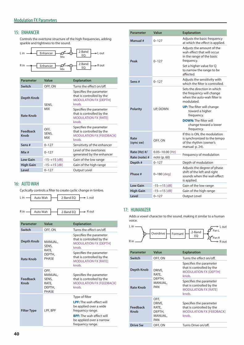
40
Modulation FX Parameters
15: ENHANCERControls the overtone structure of the high frequencies, adding sparkle and tightness to the sound.
L in
R in
L out
R outMix
MixEnhancer
Enhancer 2-BandEQ
2-BandEQ
Parameter Value Explanation
Switch OFF, ON Turns the effect on/off.
Depth Knob
SENS, MIX
Specifies the parameter that is controlled by the MODULATION FX [DEPTH] knob.
Rate Knob
Specifies the parameter that is controlled by the MODULATION FX [RATE] knob.
Feedback Knob
OFF, SENS, MIX
Specifies the parameter that is controlled by the MODULATION FX [FEEDBACK] knob.
Sens # 0–127 Sensitivity of the enhancer
Mix # 0–127 Level of the overtones generated by the enhancer
Low Gain -15–+15 [dB] Gain of the low range
High Gain -15–+15 [dB] Gain of the high range
Level 0–127 Output Level
16: AUTO WAHCyclically controls a filter to create cyclic change in timbre.
L in
R in
L out
R out
Auto Wah
2-Band EQ
2-Band EQ
Auto Wah
Parameter Value Explanation
Switch OFF, ON Turns the effect on/off.
Depth Knob MANUAL, SENS, RATE, DEPTH, PHASE
Specifies the parameter that is controlled by the MODULATION FX [DEPTH] knob.
Rate Knob
Specifies the parameter that is controlled by the MODULATION FX [RATE] knob.
Feedback Knob
OFF, MANUAL, SENS, RATE, DEPTH, PHASE
Specifies the parameter that is controlled by the MODULATION FX [FEEDBACK] knob.
Filter Type LPF, BPF
Type of filter
LPF: The wah effect will be applied over a wide frequency range.
BPF: The wah effect will be applied over a narrow frequency range.
Parameter Value Explanation
Manual # 0–127 Adjusts the basic frequency at which the effect is applied.
Peak 0–127
Adjusts the amount of the wah effect that will occur in the range of the basic frequency.
Set a higher value for Q to narrow the range to be affected.
Sens # 0–127 Adjusts the sensitivity with which the filter is controlled.
Polarity UP, DOWN
Sets the direction in which the frequency will change when the auto-wah filter is modulated.
UP: The filter will change toward a higher frequency.
DOWN: The filter will change toward a lower frequency.
Rate (sync sw) OFF, ON
If this is ON, the modulation is synchronized to the tempo of the rhythm (owner’s manual: p. 24).
Rate (Hz) #/
Rate (note) #
0.05–10.00 [Hz]Frequency of modulation
note (p. 60)
Depth # 0–127 Depth of modulation
Phase # 0–180 [deg]
Adjusts the degree of phase shift of the left and right sounds when the wah effect is applied.
Low Gain -15–+15 [dB] Gain of the low range
High Gain -15–+15 [dB] Gain of the high range
Level 0–127 Output Level
17: HUMANIZERAdds a vowel character to the sound, making it similar to a human voice.
Formant 2-BandEQ
L in
R in
Overdrive
L out
R outPan R
Pan L
Parameter Value Explanation
Switch OFF, ON Turns the effect on/off.
Depth Knob DRIVE, RATE, DEPTH, MANUAL, PAN
Specifies the parameter that is controlled by the MODULATION FX [DEPTH] knob.
Rate Knob
Specifies the parameter that is controlled by the MODULATION FX [RATE] knob.
Feedback Knob
OFF, DRIVE, RATE, DEPTH, MANUAL, PAN
Specifies the parameter that is controlled by the MODULATION FX [FEEDBACK] knob.
Drive Sw OFF, ON Turns Drive on/off.

41
Modulation FX Parameters
Parameter Value Explanation
Drive # 0–127Degree of distortion
Also changes the volume.
Vowel1 A, E, I, O, USelects the vowel.
Vowel2 A, E, I, O, U
Rate (sync sw) OFF, ON
If this is ON, the modulation is synchronized to the tempo of the rhythm (owner’s manual: p. 24).
Rate (Hz) # /
Rate (note) #
0.05–10.00 [Hz] Frequency at which the two vowels switchnote (p. 60)
Depth # 0–127 Effect depth
Input Sync Sw OFF, ON
LFO reset on/off
Determines whether the LFO for switching the vowels is reset by the input signal (ON) or not (OFF).
Input Sync Threshold 0–127 Volume level at which reset
is applied
Manual # 0–100
Point at which Vowel 1/2 switch
49 or less: Vowel 1 will have a longer duration.
50: Vowel 1 and 2 will be of equal duration.
51 or more: Vowel 2 will have a longer duration.
Low Gain -15–+15 [dB] Gain of the low frequency range
High Gain -15–+15 [dB] Gain of the high frequency range
Pan # L64–63R Stereo location of the output
Level 0–127 Output level
18: PHASER 1A phase-shifted sound is added to the original sound and modulated.
R in R out
L in L outPhaserMix
2-BandEQ
Phaser 2-BandEQ
Mix
Parameter Value Explanation
Switch OFF, ON Turns the effect on/off.
Depth KnobMANUAL, RATE, RESONANCE, MIX
Specifies the parameter that is controlled by the MODULATION FX [DEPTH] knob.
Rate Knob
Specifies the parameter that is controlled by the MODULATION FX [RATE] knob.
Feedback Knob
OFF, MANUAL, RATE, RESONANCE, MIX
Specifies the parameter that is controlled by the MODULATION FX [FEEDBACK] knob.
Parameter Value Explanation
Mode4-STAGE, 8-STAGE, 12-STAGE
Number of stages in the phaser
Manual # 0–127Adjusts the basic frequency from which the sound will be modulated.
Rate (sync sw) OFF, ON
If this is ON, the modulation is synchronized to the tempo of the rhythm (owner’s manual: p. 24).
Rate (Hz) #/
Rate (note) #
0.05–10.00 [Hz]Frequency of modulation
note (p. 60)
Depth 0–127 Depth of modulation
Polarity INVERSE, SYNCHRO
Selects whether the left and right phase of the modulation will be the same or the opposite.
INVERSE: The left and right phase will be opposite. When using a mono source, this spreads the sound.
SYNCHRO: The left and right phase will be the same. Select this when inputting a stereo source.
Resonance # 0–127 Amount of feedback
Cross Feedback -98–+98 [%]
Adjusts the proportion of the phaser sound that is fed back into the effect. Negative “-” settings will invert the phase.
Mix # 0–127 Level of the phase-shifted sound
Low Gain -15–+15 [dB] Gain of the low range
High Gain -15–+15 [dB] Gain of the high range
Level 0–127 Output Level
19: STEP PHASERThis is a stereo phaser. The phaser effect will be varied gradually.
R in R out
L in L outStep PhaserMix
2-BandEQ
Step Phaser 2-BandEQ
Mix
Parameter Value Explanation
Switch OFF, ON Turns the effect on/off.
Depth Knob MANUAL, RATE, RESONANCE, STEP RATE, MIX
Specifies the parameter that is controlled by the MODULATION FX [DEPTH] knob.
Rate Knob
Specifies the parameter that is controlled by the MODULATION FX [RATE] knob.
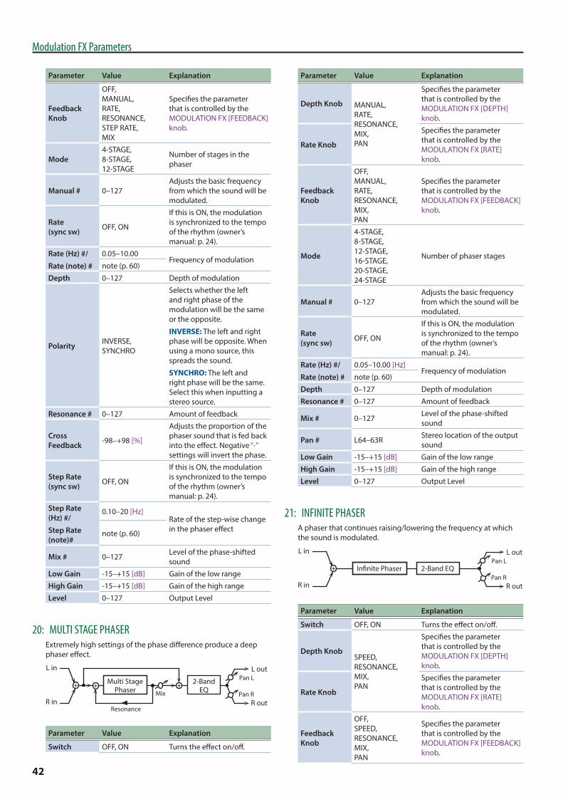
42
Modulation FX Parameters
Parameter Value Explanation
Feedback Knob
OFF, MANUAL, RATE, RESONANCE, STEP RATE, MIX
Specifies the parameter that is controlled by the MODULATION FX [FEEDBACK] knob.
Mode4-STAGE, 8-STAGE, 12-STAGE
Number of stages in the phaser
Manual # 0–127Adjusts the basic frequency from which the sound will be modulated.
Rate (sync sw) OFF, ON
If this is ON, the modulation is synchronized to the tempo of the rhythm (owner’s manual: p. 24).
Rate (Hz) #/
Rate (note) #
0.05–10.00Frequency of modulation
note (p. 60)
Depth 0–127 Depth of modulation
Polarity INVERSE, SYNCHRO
Selects whether the left and right phase of the modulation will be the same or the opposite.
INVERSE: The left and right phase will be opposite. When using a mono source, this spreads the sound.
SYNCHRO: The left and right phase will be the same. Select this when inputting a stereo source.
Resonance # 0–127 Amount of feedback
Cross Feedback -98–+98 [%]
Adjusts the proportion of the phaser sound that is fed back into the effect. Negative “-” settings will invert the phase.
Step Rate (sync sw) OFF, ON
If this is ON, the modulation is synchronized to the tempo of the rhythm (owner’s manual: p. 24).
Step Rate (Hz) #/
Step Rate (note)#
0.10–20 [Hz]Rate of the step-wise change in the phaser effectnote (p. 60)
Mix # 0–127 Level of the phase-shifted sound
Low Gain -15–+15 [dB] Gain of the low range
High Gain -15–+15 [dB] Gain of the high range
Level 0–127 Output Level
20: MULTI STAGE PHASERExtremely high settings of the phase difference produce a deep phaser effect.
Resonance
Mix
L in
R in
L out
R outPan R
Pan L2-BandEQ
Multi StagePhaser
Parameter Value Explanation
Switch OFF, ON Turns the effect on/off.
Parameter Value Explanation
Depth Knob MANUAL, RATE, RESONANCE, MIX, PAN
Specifies the parameter that is controlled by the MODULATION FX [DEPTH] knob.
Rate Knob
Specifies the parameter that is controlled by the MODULATION FX [RATE] knob.
Feedback Knob
OFF, MANUAL, RATE, RESONANCE, MIX, PAN
Specifies the parameter that is controlled by the MODULATION FX [FEEDBACK] knob.
Mode
4-STAGE, 8-STAGE, 12-STAGE, 16-STAGE, 20-STAGE, 24-STAGE
Number of phaser stages
Manual # 0–127Adjusts the basic frequency from which the sound will be modulated.
Rate (sync sw) OFF, ON
If this is ON, the modulation is synchronized to the tempo of the rhythm (owner’s manual: p. 24).
Rate (Hz) #/
Rate (note) #
0.05–10.00 [Hz]Frequency of modulation
note (p. 60)
Depth 0–127 Depth of modulation
Resonance # 0–127 Amount of feedback
Mix # 0–127 Level of the phase-shifted sound
Pan # L64–63R Stereo location of the output sound
Low Gain -15–+15 [dB] Gain of the low range
High Gain -15–+15 [dB] Gain of the high range
Level 0–127 Output Level
21: INFINITE PHASERA phaser that continues raising/lowering the frequency at which the sound is modulated.
In�nite Phaser 2-Band EQ
L in
R in
L out
R outPan R
Pan L
Parameter Value Explanation
Switch OFF, ON Turns the effect on/off.
Depth KnobSPEED, RESONANCE, MIX, PAN
Specifies the parameter that is controlled by the MODULATION FX [DEPTH] knob.
Rate Knob
Specifies the parameter that is controlled by the MODULATION FX [RATE] knob.
Feedback Knob
OFF, SPEED, RESONANCE, MIX, PAN
Specifies the parameter that is controlled by the MODULATION FX [FEEDBACK] knob.

43
Modulation FX Parameters
Parameter Value Explanation
Mode 1, 2, 3, 4 Higher values will produce a deeper phaser effect.
Speed # -100–+100
Speed at which to raise or lower the frequency at which the sound is modulated (+: upward / -: downward)
Resonance # 0–127 Amount of feedback
Mix # 0–127 Volume of the phase-shifted sound
Pan # L64–63R Panning of the output sound
Low Gain -15–+15 [dB] Gain of the low frequency range
High Gain -15–+15 [dB] Gain of the high frequency range
Level 0–127 Output volume
22: RING MODULATORThis is an effect that applies amplitude modulation (AM) to the input signal, producing bell-like sounds. You can also change the modulation frequency in response to changes in the volume of the sound sent into the effect.
L in
R in
L out
R out
Ring Mod
2-Band EQ
2-Band EQ
Ring Mod
Parameter Value Explanation
Switch OFF, ON Turns the effect on/off.
Depth KnobFREQUENCY, SENS, BALANCE
Specifies the parameter that is controlled by the MODULATION FX [DEPTH] knob.
Rate Knob
Specifies the parameter that is controlled by the MODULATION FX [RATE] knob.
Feedback Knob
OFF, FREQUENCY, SENS, BALANCE
Specifies the parameter that is controlled by the MODULATION FX [FEEDBACK] knob.
Frequency # 0–127 Adjusts the frequency at which modulation is applied.
Sens # 0–127Adjusts the amount of frequency modulation applied.
Polarity UP, DOWN
Determines whether the frequency modulation moves towards higher frequencies (UP) or lower frequencies (DOWN).
Low Gain -15–+15 [dB] Gain of the low frequency range
High Gain -15–+15 [dB] Gain of the high frequency range
Balance # D100:0W–D0:100W
Volume balance between the direct sound (D) and the effect sound (W)
Level 0–127 Output level
23: TREMOLOCyclically modulates the volume to add tremolo effect to the sound.
L in
R in
L out
R out
Tremolo
2-Band EQ
2-Band EQ
Tremolo
Parameter Value Explanation
Switch OFF, ON Turns the effect on/off.
Depth KnobRATE, DEPTH, MOD WAVE
Specifies the parameter that is controlled by the MODULATION FX [DEPTH] knob.
Rate Knob
Specifies the parameter that is controlled by the MODULATION FX [RATE] knob.
Feedback Knob
OFF, RATE, DEPTH, MOD WAVE
Specifies the parameter that is controlled by the MODULATION FX [FEEDBACK] knob.
Mod Wave
TRI, SQR, SIN, SAW1, SAW2
Modulation wave
TRI: triangle wave
SQR: square wave
SIN: sine wave
SAW1/2: sawtooth wave
SAW1 SAW2
Rate (sync sw) OFF, ON
If this is ON, the modulation is synchronized to the tempo of the rhythm (owner’s manual: p. 24).
Rate (Hz) #/
Rate (note) #
0.05–10.00 [Hz]Frequency of the change
note (p. 60)
Depth # 0–127 Depth to which the effect is applied
Low Gain -15–+15 [dB] Gain of the low range
High Gain -15–+15 [dB] Gain of the high range
Level 0–127 Output Level
24: AUTO PANCyclically modulates the stereo location of the sound.
L in
R in
L out
R out
Auto Pan
2-Band EQ
2-Band EQ
Auto Pan
Parameter Value Explanation
Switch OFF, ON Turns the effect on/off.
Depth KnobRATE, DEPTH, MOD WAVE
Specifies the parameter that is controlled by the MODULATION FX [DEPTH] knob.
Rate Knob
Specifies the parameter that is controlled by the MODULATION FX [RATE] knob.

44
Modulation FX Parameters
Parameter Value Explanation
Feedback Knob
OFF, RATE, DEPTH, MOD WAVE
Specifies the parameter that is controlled by the MODULATION FX [FEEDBACK] knob.
Mod Wave
TRI, SQR, SIN, SAW1, SAW2
Modulation wave
TRI: triangle wave
SQR: square wave
SIN: sine wave
SAW1/2: sawtooth wave
SAW1 SAW2R R
L L
Rate (sync sw) OFF, ON
If this is ON, the modulation is synchronized to the tempo of the rhythm (owner’s manual: p. 24).
Rate (Hz) #/
Rate (note) #
0.05–10.00 [Hz]Frequency of the change
note (p. 60)
Depth # 0–127 Depth to which the effect is applied
Low Gain -15–+15 [dB] Gain of the low range
High Gain -15–+15 [dB] Gain of the high range
Level 0–127 Output Level
25: SLICERBy applying successive cuts to the sound, this effect turns a conventional sound into a sound that appears to be played as a backing phrase. This is especially effective when applied to sustain-type sounds.
L in
R in
L out
R out
Slicer
Slicer
Parameter Value Explanation
Switch OFF, ON Turns the effect on/off.
Depth KnobRATE, ATTACK, SHUFFLE
Specifies the parameter that is controlled by the MODULATION FX [DEPTH] knob.
Rate Knob
Specifies the parameter that is controlled by the MODULATION FX [RATE] knob.
Feedback Knob
OFF, RATE, ATTACK, SHUFFLE
Specifies the parameter that is controlled by the MODULATION FX [FEEDBACK] knob.
Step 01–16 0–127 Level at each step
Rate (sync sw) OFF, ON
If this is ON, the modulation is synchronized to the tempo of the rhythm (owner’s manual: p. 24).
Rate (Hz) #/
Rate (note) #
0.05–10.00 [Hz] Rate at which the 16-step sequence will cyclenote (p. 60)
Attack # 0–127 Speed at which the level changes between steps
Parameter Value Explanation
Input Sync Sw OFF, ON
Specifies whether an input note will cause the sequence to resume from the first step of the sequence (ON) or not (OFF)
Input Sync Threshold 0–127 Volume at which an input
note will be detected
Mode LEGATO, SLASH
Sets the manner in which the volume changes as one step progresses to the next.
LEGATO: The change in volume from one step’s level to the next remains unaltered. If the level of a following step is the same as the one preceding it, there is no change in volume.
SLASH: The level is momentarily set to 0 before progressing to the level of the next step. This change in volume occurs even if the level of the following step is the same as the preceding step.
Shuffle # 0–127
Timing of volume changes in levels for even-numbered steps (step 2, step 4, step 6...).
The higher the value, the later the beat progresses.
Level 0–127 Output level
26: CHORUSThis is a stereo chorus. A filter is provided so that you can adjust the timbre of the chorus sound.
L in
R in
Chorus
Chorus
L out
R out
2-BandEQ
2-BandEQ
Balance W
Balance W
Balance D
Balance D
Parameter Value Explanation
Switch OFF, ON Turns the effect on/off.
Depth KnobRATE, BALANCE, DEPTH
Specifies the parameter that is controlled by the MODULATION FX [DEPTH] knob.
Rate Knob
Specifies the parameter that is controlled by the MODULATION FX [RATE] knob.
Feedback Knob
OFF, RATE, BALANCE, DEPTH
Specifies the parameter that is controlled by the MODULATION FX [FEEDBACK] knob.

45
Modulation FX Parameters
Parameter Value Explanation
Filter TypeOFF, LPF, HPF
Type of filter
OFF: no filter is used
LPF: cuts the frequency range above the Cutoff Freq
HPF: cuts the frequency range below the Cutoff Freq
Cutoff Freq 200–8000 [Hz] Basic frequency of the filter
Pre Delay 0.0–100 [msec]Adjusts the delay time from the direct sound until the chorus sound is heard.
Rate (sync sw) OFF, ON
If this is ON, the modulation is synchronized to the tempo of the rhythm (owner’s manual: p. 24).
Rate (Hz) #/
Rate (note) #
0.05–10.00 [Hz]Frequency of modulation
note (p. 60)
Depth 0–127 Depth of modulation
Phase 0–180 [deg] Spatial spread of the sound
Low Gain -15–+15 [dB] Gain of the low range
High Gain -15–+15 [dB] Gain of the high range
Balance # D100:0W–D0:100W
Volume balance between the direct sound (D) and the chorus sound (W)
Level 0–127 Output Level
27: FLANGERThis is a stereo flanger. (The LFO has the same phase for left and right.) It produces a metallic resonance that rises and falls like a jet airplane taking off or landing. A filter is provided so that you can adjust the timbre of the flanged sound.
R in R out
L in L out
Flanger
FeedbackFeedback
Flanger
Balance W
Balance D
Balance W
Balance D
2-BandEQ
2-BandEQ
Parameter Value Explanation
Switch OFF, ON Turns the effect on/off.
Depth KnobRATE, FEEDBACK, BALANCE
Specifies the parameter that is controlled by the MODULATION FX [DEPTH] knob.
Rate Knob
Specifies the parameter that is controlled by the MODULATION FX [RATE] knob.
Feedback Knob
OFF, RATE, FEEDBACK, BALANCE
Specifies the parameter that is controlled by the MODULATION FX [FEEDBACK] knob.
Filter TypeOFF, LPF, HPF
Type of filter
OFF: no filter is used
LPF: cuts the frequency range above the Cutoff Freq
HPF: cuts the frequency range below the Cutoff Freq
Parameter Value Explanation
Cutoff Freq 200–8000 [Hz] Basic frequency of the filter
Pre Delay 0.0–100 [msec]Adjusts the delay time from the direct sound until the flanger sound is heard.
Rate (sync sw) OFF, ON
If this is ON, the modulation is synchronized to the tempo of the rhythm (owner’s manual: p. 24).
Rate (Hz) #/
Rate (note) #
0.05–10.00 [Hz]Frequency of modulation
note (p. 60)
Depth 0–127 Depth of modulation
Phase 0–180 [deg] Spatial spread of the sound
Feedback # -98–+98 [%]
Adjusts the proportion of the flanger sound that is fed back into the effect. Negative “-” settings will invert the phase.
Low Gain -15–+15 [dB] Gain of the low range
High Gain -15–+15 [dB] Gain of the high range
Balance # D100:0W–D0:100W
Volume balance between the direct sound (D) and the flanger sound (W)
Level 0–127 Output Level
28: STEP FLANGERThis is a flanger in which the flanger pitch changes in steps. The speed at which the pitch changes can also be specified in terms of a note-value of a specified tempo.
R in R out
L in L out
FeedbackFeedback
Balance W
Balance D
Balance W
Balance D
2-BandEQ
2-BandEQ
Step Flanger
Step Flanger
Parameter Value Explanation
Switch OFF, ON Turns the effect on/off.
Depth KnobRATE, FEEDBACK, STEP RATE, BALANCE
Specifies the parameter that is controlled by the MODULATION FX [DEPTH] knob.
Rate Knob
Specifies the parameter that is controlled by the MODULATION FX [RATE] knob.
Feedback Knob
OFF, RATE, FEEDBACK, STEP RATE, BALANCE
Specifies the parameter that is controlled by the MODULATION FX [FEEDBACK] knob.
Filter TypeOFF, LPF, HPF
Type of filter
OFF: no filter is used
LPF: cuts the frequency range above the Cutoff Freq
HPF: cuts the frequency range below the Cutoff Freq
Cutoff Freq 200–8000 [Hz] Basic frequency of the filter

46
Modulation FX Parameters
Parameter Value Explanation
Pre Delay 0.0–100 [msec]Adjusts the delay time from the direct sound until the flanger sound is heard.
Rate (sync sw) OFF, ON
If this is ON, the modulation is synchronized to the tempo of the rhythm (owner’s manual: p. 24).
Rate (Hz) #/
Rate (note) #
0.05–10.00 [Hz]Frequency of modulation
note (p. 60)
Depth 0–127 Depth of modulation
Phase 0–180 [deg] Spatial spread of the sound
Feedback # -98–+98 [%]
Adjusts the proportion of the flanger sound that is fed back into the effect. Negative “-” settings will invert the phase.
Step Rate (sync sw) OFF, ON
If this is ON, the modulation is synchronized to the tempo of the rhythm (owner’s manual: p. 24).
Step Rate (Hz) #/
Step Rate (note)#
0.10–20.00 [Hz]
Rate (period) of pitch changenote (p. 60)
Low Gain -15–+15 [dB] Gain of the low range
High Gain -15–+15 [dB] Gain of the high range
Balance # D100:0W–D0:100W
Volume balance between the direct sound (D) and the flanger sound (W)
Level 0–127 Output Level
29: HEXA-CHORUSUses a six-phase chorus (six layers of chorused sound) to give richness and spatial spread to the sound.
Balance W
Balance W
L in
R in
L out
R out
Hexa Chorus
Balance D
Balance D
Parameter Value Explanation
Switch OFF, ON Turns the effect on/off.
Depth KnobRATE, BALANCE, DEPTH
Specifies the parameter that is controlled by the MODULATION FX [DEPTH] knob.
Rate Knob
Specifies the parameter that is controlled by the MODULATION FX [RATE] knob.
Feedback Knob
OFF, RATE, BALANCE, DEPTH
Specifies the parameter that is controlled by the MODULATION FX [FEEDBACK] knob.
Pre Delay 0.0–100 [msec]Adjusts the delay time from the direct sound until the chorus sound is heard.
Rate (sync sw) OFF, ON
If this is ON, the modulation is synchronized to the tempo of the rhythm (owner’s manual: p. 24).
Parameter Value Explanation
Rate (Hz) #/
Rate (note) #
0.05–10.00 [Hz]Frequency of modulation
note (p. 60)
Depth 0–127 Depth of modulation
Pre Delay Deviation 0–20
Adjusts the differences in Pre Delay between each chorus sound.
Depth Deviation -20–+20
Adjusts the difference in modulation depth between each chorus sound.
Pan Deviation 0–20
Adjusts the difference in stereo location between each chorus sound.
0: All chorus sounds will be in the center.
20: Each chorus sound will be spaced at 60 degree intervals relative to the center.
Balance # D100:0W–D0:100W
Volume balance between the direct sound (D) and the chorus sound (W)
Level 0–127 Output Level
30: TREMOLO CHORUSThis is a chorus effect with added Tremolo (cyclic modulation of volume).
Tremolo Chorus
L in
R in
L out
R outBalance D
Balance D
Balance W
Balance W
Parameter Value Explanation
Switch OFF, ON Turns the effect on/off.
Depth KnobCHORUS RATE, TREMOLO RATE, BALANCE
Specifies the parameter that is controlled by the MODULATION FX [DEPTH] knob.
Rate Knob
Specifies the parameter that is controlled by the MODULATION FX [RATE] knob.
Feedback Knob
OFF, CHORUS RATE, TREMOLO RATE, BALANCE
Specifies the parameter that is controlled by the MODULATION FX [FEEDBACK] knob.
Pre Delay 0.0–100 [msec]Adjusts the delay time from the direct sound until the chorus sound is heard.
Chorus Rate (sync sw) OFF, ON
If this is ON, the modulation is synchronized to the tempo of the rhythm (owner’s manual: p. 24).
Chorus Rate (Hz) #/
Chorus Rate (note) #
0.05–10.00 [Hz]Modulation frequency of the chorus effectnote (p. 60)
Chorus Depth 0–127 Modulation depth of the chorus effect
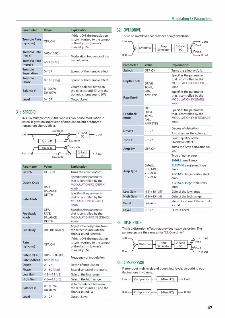
47
Modulation FX Parameters
Parameter Value Explanation
Tremolo Rate (sync sw) OFF, ON
If this is ON, the modulation is synchronized to the tempo of the rhythm (owner’s manual: p. 24).
Tremolo Rate (Hz) #/
Tremolo Rate (note) #
0.05–10.00Modulation frequency of the tremolo effectnote (p. 60)
Tremolo Separation 0–127 Spread of the tremolo effect
Tremolo Phase 0–180 [deg] Spread of the tremolo effect
Balance # D100:0W–D0:100W
Volume balance between the direct sound (D) and the tremolo chorus sound (W)
Level 0–127 Output Level
31: SPACE-DThis is a multiple chorus that applies two-phase modulation in stereo. It gives no impression of modulation, but produces a transparent chorus effect.
L in
R in
Space D
Space D
L out
R out
2-BandEQ
2-BandEQ
Balance W
Balance W
Balance D
Balance D
Parameter Value Explanation
Switch OFF, ON Turns the effect on/off.
Depth KnobRATE, BALANCE, DEPTH
Specifies the parameter that is controlled by the MODULATION FX [DEPTH] knob.
Rate Knob
Specifies the parameter that is controlled by the MODULATION FX [RATE] knob.
Feedback Knob
OFF, RATE, BALANCE, DEPTH
Specifies the parameter that is controlled by the MODULATION FX [FEEDBACK] knob.
Pre Delay 0.0–100 [msec]Adjusts the delay time from the direct sound until the chorus sound is heard.
Rate (sync sw) OFF, ON
If this is ON, the modulation is synchronized to the tempo of the rhythm (owner’s manual: p. 24).
Rate (Hz) #/
Rate (note) #
0.05–10.00 [Hz]Frequency of modulation
note (p. 60)
Depth 0–127 Depth of modulation
Phase 0–180 [deg] Spatial spread of the sound
Low Gain -15–+15 [dB] Gain of the low range
High Gain -15–+15 [dB] Gain of the high range
Balance # D100:0W–D0:100W
Volume balance between the direct sound (D) and the chorus sound (W)
Level 0–127 Output Level
32: OVERDRIVEThis is an overdrive that provides heavy distortion.
L in
R in
L out
R outPan R
Pan LAmpSimulator
2-BandEQ
Overdrive
Parameter Value Explanation
Switch OFF, ON Turns the effect on/off.
Depth KnobDRIVE, TONE, PAN, AMP TYPE
Specifies the parameter that is controlled by the MODULATION FX [DEPTH] knob.
Rate Knob
Specifies the parameter that is controlled by the MODULATION FX [RATE] knob.
Feedback Knob
OFF, DRIVE, TONE, PAN, AMP TYPE
Specifies the parameter that is controlled by the MODULATION FX [FEEDBACK] knob.
Drive # 0–127Degree of distortion
Also changes the volume.
Tone # 0–127 Sound quality of the Overdrive effect
Amp Sw OFF, ON Turns the Amp Simulator on/off.
Amp Type
SMALL, BUILT-IN, 2-STACK, 3-STACK
Type of guitar amp
SMALL: small amp
BUILT-IN: single-unit type amp
2-STACK: large double stack amp
3-STACK: large triple stack amp
Low Gain -15–+15 [dB] Gain of the low range
High Gain -15–+15 [dB] Gain of the high range
Pan # L64–63R Stereo location of the output sound
Level 0–127 Output Level
33: DISTORTIONThis is a distortion effect that provides heavy distortion. The parameters are the same as for “32: Overdrive.”
L in
R in
L out
R outPan R
Pan LAmpSimulator
2-BandEQ
Distortion
34: COMPRESSORFlattens out high levels and boosts low levels, smoothing out fluctuations in volume.
L in
R in
L out
R out
Compressor
2-Band EQ
2-Band EQ
Compressor

48
Modulation FX Parameters
Parameter Value Explanation
Switch OFF, ON Turns the effect on/off.
Depth KnobATTACK, THRESHOLD, LEVEL
Specifies the parameter that is controlled by the MODULATION FX [DEPTH] knob.
Rate Knob
Specifies the parameter that is controlled by the MODULATION FX [RATE] knob.
Feedback Knob
OFF, ATTACK, THRESHOLD, LEVEL
Specifies the parameter that is controlled by the MODULATION FX [FEEDBACK] knob.
Attack # 0–127Sets the time it takes until the level is compressed after the input exceeds the Threshold.
Threshold # 0–127 Adjusts the volume at which compression begins
Post Gain 0–+18 [dB] Adjusts the output gain.
Low Gain -15–+15 [dB] Gain of the low frequency range
High Gain -15–+15 [dB] Gain of the high frequency range
Level # 0–127 Output Level
35: LIMITERCompresses signals that exceed a specified volume level, preventing distortion from occurring.
L in
R in
L out
R out
Limiter
2-Band EQ
2-Band EQ
Limiter
Parameter Value Explanation
Switch OFF, ON Turns the effect on/off.
Depth KnobRELEASE, THRESHOLD, LEVEL
Specifies the parameter that is controlled by the MODULATION FX [DEPTH] knob.
Rate Knob
Specifies the parameter that is controlled by the MODULATION FX [RATE] knob.
Feedback Knob
OFF, RELEASE, THRESHOLD, LEVEL
Specifies the parameter that is controlled by the MODULATION FX [FEEDBACK] knob.
Release # 0–127
Adjusts the time after the signal volume falls below the Threshold Level until compression is no longer applied.
Threshold # 0–127 Adjusts the volume at which compression begins
Ratio 1.5:1, 2:1, 4:1, 100:1 Compression ratio
Post Gain 0–+18 [dB] Adjusts the output gain.
Low Gain -15–+15 [dB] Gain of the low frequency range
High Gain -15–+15 [dB] Gain of the high frequency range
Parameter Value Explanation
Level # 0–127 Output Level
36: SUSTAINERThis effect compresses high input and boosts low input, making the volume consistent and producing undistorted sustain.
L in
R in
L out
R out
Sustainer
2-Band EQ
2-Band EQ
Sustainer
Parameter Value Explanation
Switch OFF, ON Turns the effect on/off.
Depth KnobSUSTAIN, ATTACK, RELEASE, LEVEL
Specifies the parameter that is controlled by the MODULATION FX [DEPTH] knob.
Rate Knob
Specifies the parameter that is controlled by the MODULATION FX [RATE] knob.
Feedback Knob
OFF, SUSTAIN, ATTACK, RELEASE, LEVEL
Specifies the parameter that is controlled by the MODULATION FX [FEEDBACK] knob.
Sustain # 0–127
Adjusts the range of volume for which low input signals are boosted to make the volume consistent.
Higher settings produce longer sustain.
Attack 0–127 Time until the volume is compressed
Release 0–127 Time until compression ends
Post Gain -15–+15 [dB] Adjusts the output gain.
Low Gain -15–+15 [dB] Gain of the low frequency range
High Gain -15–+15 [dB] Gain of the high frequency range
Level # 0–127 Output Level
37: GATECuts the reverb’s delay according to the volume of the sound sent into the effect. Use this when you want to create an artificial-sounding decrease in the reverb’s decay.
L in
R in
L out
R out
Gate
Gate
Parameter Value Explanation
Switch OFF, ON Turns the effect on/off.
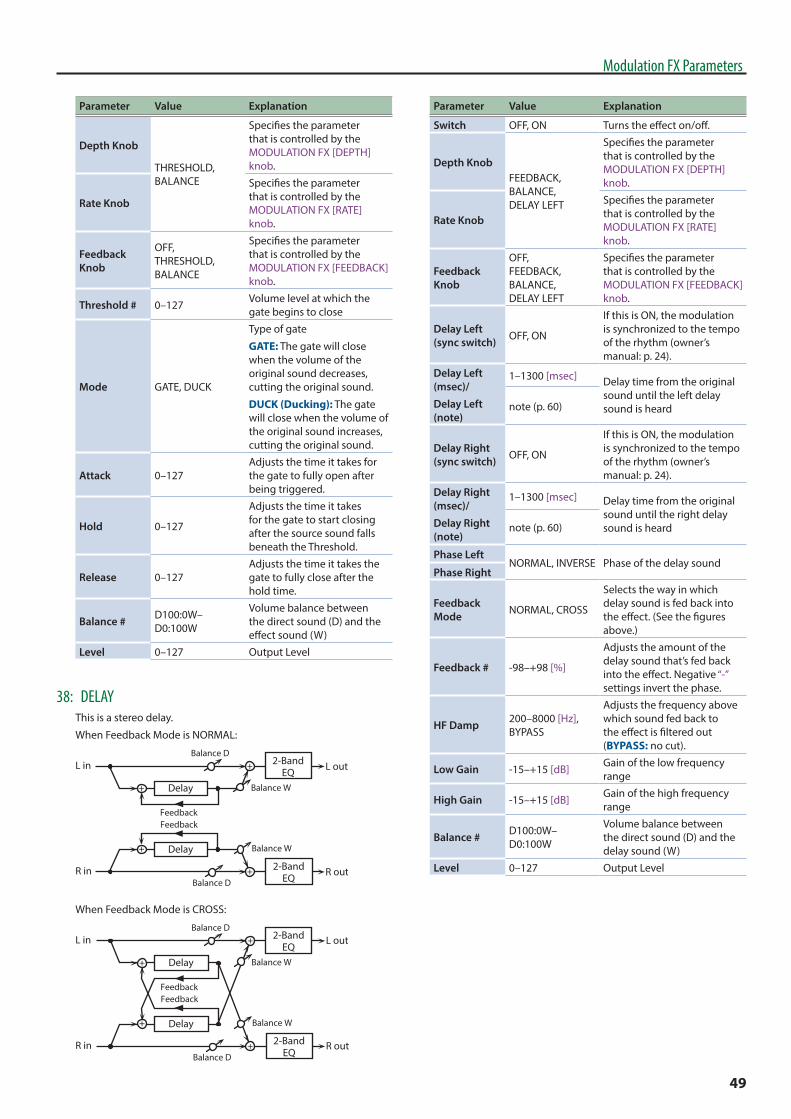
49
Modulation FX Parameters
Parameter Value Explanation
Depth Knob
THRESHOLD, BALANCE
Specifies the parameter that is controlled by the MODULATION FX [DEPTH] knob.
Rate Knob
Specifies the parameter that is controlled by the MODULATION FX [RATE] knob.
Feedback Knob
OFF, THRESHOLD, BALANCE
Specifies the parameter that is controlled by the MODULATION FX [FEEDBACK] knob.
Threshold # 0–127 Volume level at which the gate begins to close
Mode GATE, DUCK
Type of gate
GATE: The gate will close when the volume of the original sound decreases, cutting the original sound.
DUCK (Ducking): The gate will close when the volume of the original sound increases, cutting the original sound.
Attack 0–127Adjusts the time it takes for the gate to fully open after being triggered.
Hold 0–127
Adjusts the time it takes for the gate to start closing after the source sound falls beneath the Threshold.
Release 0–127Adjusts the time it takes the gate to fully close after the hold time.
Balance # D100:0W–D0:100W
Volume balance between the direct sound (D) and the effect sound (W)
Level 0–127 Output Level
38: DELAYThis is a stereo delay.
When Feedback Mode is NORMAL:
R in R out
L in L out
FeedbackFeedback
Balance W
Balance D
Balance W
Balance D
2-BandEQ
2-BandEQ
Delay
Delay
When Feedback Mode is CROSS:
R in R out
L in L out
FeedbackFeedback
Balance W
Balance D
Balance W
Balance D
2-BandEQ
2-BandEQ
Delay
Delay
Parameter Value Explanation
Switch OFF, ON Turns the effect on/off.
Depth KnobFEEDBACK, BALANCE, DELAY LEFT
Specifies the parameter that is controlled by the MODULATION FX [DEPTH] knob.
Rate Knob
Specifies the parameter that is controlled by the MODULATION FX [RATE] knob.
Feedback Knob
OFF, FEEDBACK, BALANCE, DELAY LEFT
Specifies the parameter that is controlled by the MODULATION FX [FEEDBACK] knob.
Delay Left (sync switch) OFF, ON
If this is ON, the modulation is synchronized to the tempo of the rhythm (owner’s manual: p. 24).
Delay Left (msec)/
Delay Left (note)
1–1300 [msec] Delay time from the original sound until the left delay sound is heardnote (p. 60)
Delay Right (sync switch) OFF, ON
If this is ON, the modulation is synchronized to the tempo of the rhythm (owner’s manual: p. 24).
Delay Right (msec)/
Delay Right (note)
1–1300 [msec] Delay time from the original sound until the right delay sound is heardnote (p. 60)
Phase LeftNORMAL, INVERSE Phase of the delay sound
Phase Right
Feedback Mode NORMAL, CROSS
Selects the way in which delay sound is fed back into the effect. (See the figures above.)
Feedback # -98–+98 [%]
Adjusts the amount of the delay sound that’s fed back into the effect. Negative “-” settings invert the phase.
HF Damp 200–8000 [Hz], BYPASS
Adjusts the frequency above which sound fed back to the effect is filtered out (BYPASS: no cut).
Low Gain -15–+15 [dB] Gain of the low frequency range
High Gain -15–+15 [dB] Gain of the high frequency range
Balance # D100:0W–D0:100W
Volume balance between the direct sound (D) and the delay sound (W)
Level 0–127 Output Level
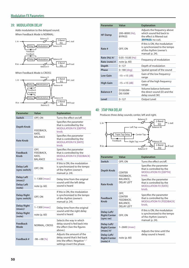
50
Modulation FX Parameters
39: MODULATION DELAYAdds modulation to the delayed sound.
When Feedback Mode is NORMAL:
R in R out
L in L out
FeedbackFeedback
Balance W
Balance D
Balance W
Balance D
2-BandEQ
2-BandEQ
Delay
Delay
Modulation
Modulation
When Feedback Mode is CROSS:
R in R out
L in L out
FeedbackFeedback
Balance W
Balance D
Balance W
Balance D
2-BandEQ
2-BandEQ
Delay
Delay
Modulation
Modulation
Parameter Value Explanation
Switch OFF, ON Turns the effect on/off.
Depth KnobFEEDBACK, RATE, BALANCE
Specifies the parameter that is controlled by the MODULATION FX [DEPTH] knob.
Rate Knob
Specifies the parameter that is controlled by the MODULATION FX [RATE] knob.
Feedback Knob
OFF, FEEDBACK, RATE, BALANCE
Specifies the parameter that is controlled by the MODULATION FX [FEEDBACK] knob.
Delay Left (sync switch) OFF, ON
If this is ON, the modulation is synchronized to the tempo of the rhythm (owner’s manual: p. 24).
Delay Left (msec)/
Delay Left (note)
1–1300 [msec] Delay time from the original sound until the left delay sound is heardnote (p. 60)
Delay Right (sync switch) OFF, ON
If this is ON, the modulation is synchronized to the tempo of the rhythm (owner’s manual: p. 24).
Delay Right (msec)/
Delay Right (note)
1–1300 [msec] Delay time from the original sound until the right delay sound is heardnote (p. 60)
Feedback Mode NORMAL, CROSS
Selects the way in which delay sound is fed back into the effect (See the figures above.)
Feedback # -98–+98 [%]
Adjusts the amount of the delay sound that’s fed back into the effect. Negative “-” settings invert the phase.
Parameter Value Explanation
HF Damp 200–8000 [Hz], BYPASS
Adjusts the frequency above which sound fed back to the effect is filtered out (BYPASS: no cut).
Rate # OFF, ON
If this is ON, the modulation is synchronized to the tempo of the rhythm (owner’s manual: p. 24).
Rate (Hz) #/
Rate (note) #
0.05–10.00 [Hz]Frequency of modulation
note (p. 60)
Depth 0–127 Depth of modulation
Phase 0–180 [deg] Spatial spread of the sound
Low Gain -15–+15 [dB] Gain of the low frequency range
High Gain -15–+15 [dB] Gain of the high frequency range
Balance # D100:0W–D0:100W
Volume balance between the direct sound (D) and the delay sound (W)
Level 0–127 Output Level
40: 3TAP PAN DELAYProduces three delay sounds; center, left and right.
L in
R in
L out
R out
Left Tap
Right Tap
Triple Tap Delay
2-BandEQ
2-BandEQ
Balance W
Balance D
Balance W
Balance D
Feedback
Center Tap
Parameter Value Explanation
Switch OFF, ON Turns the effect on/off.
Depth KnobCENTER FEEDBACK, BALANCE, DELAY LEFT
Specifies the parameter that is controlled by the MODULATION FX [DEPTH] knob.
Rate Knob
Specifies the parameter that is controlled by the MODULATION FX [RATE] knob.
Feedback Knob
OFF, CENTER FEEDBACK, BALANCE, DELAY LEFT
Specifies the parameter that is controlled by the MODULATION FX [FEEDBACK] knob.
Delay Left/Right/Center (sync sw)
OFF, ON
If this is ON, the modulation is synchronized to the tempo of the rhythm (owner’s manual: p. 24).
Delay Left/Right/Center (msec) #/
Delay Left/Right/Center (note) #
1–2600 [msec]Adjusts the time until the delay sound is heard.
note (p. 60)
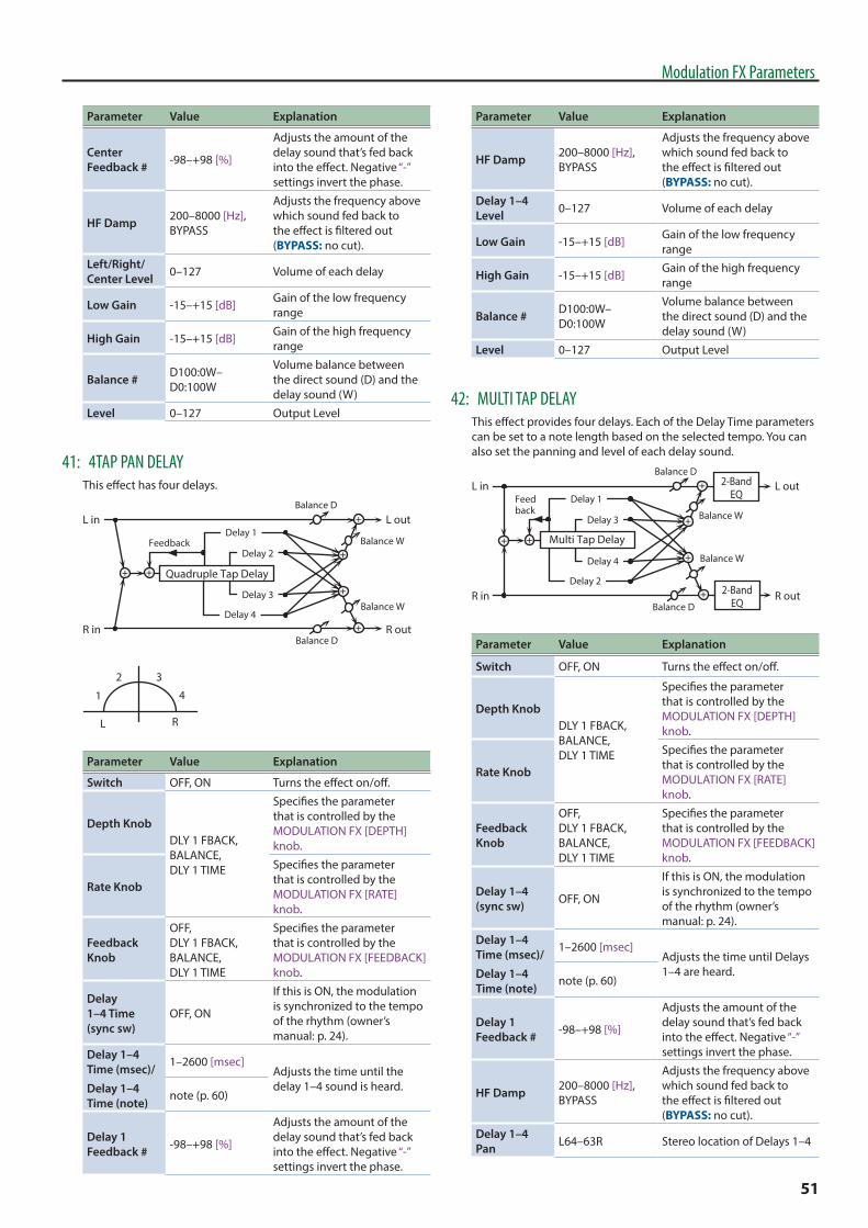
51
Modulation FX Parameters
Parameter Value Explanation
Center Feedback # -98–+98 [%]
Adjusts the amount of the delay sound that’s fed back into the effect. Negative “-” settings invert the phase.
HF Damp 200–8000 [Hz], BYPASS
Adjusts the frequency above which sound fed back to the effect is filtered out (BYPASS: no cut).
Left/Right/Center Level 0–127 Volume of each delay
Low Gain -15–+15 [dB] Gain of the low frequency range
High Gain -15–+15 [dB] Gain of the high frequency range
Balance # D100:0W–D0:100W
Volume balance between the direct sound (D) and the delay sound (W)
Level 0–127 Output Level
41: 4TAP PAN DELAYThis effect has four delays.
L in
R in
L out
R out
Quadruple Tap Delay
Balance W
Balance D
Balance W
Balance D
Delay 1
Delay 2
Delay 3
Delay 4
Feedback
1
2 3
4
L R
Parameter Value Explanation
Switch OFF, ON Turns the effect on/off.
Depth KnobDLY 1 FBACK, BALANCE, DLY 1 TIME
Specifies the parameter that is controlled by the MODULATION FX [DEPTH] knob.
Rate Knob
Specifies the parameter that is controlled by the MODULATION FX [RATE] knob.
Feedback Knob
OFF, DLY 1 FBACK, BALANCE, DLY 1 TIME
Specifies the parameter that is controlled by the MODULATION FX [FEEDBACK] knob.
Delay 1–4 Time (sync sw)
OFF, ON
If this is ON, the modulation is synchronized to the tempo of the rhythm (owner’s manual: p. 24).
Delay 1–4 Time (msec)/
Delay 1–4 Time (note)
1–2600 [msec]Adjusts the time until the delay 1–4 sound is heard.
note (p. 60)
Delay 1 Feedback # -98–+98 [%]
Adjusts the amount of the delay sound that’s fed back into the effect. Negative “-” settings invert the phase.
Parameter Value Explanation
HF Damp 200–8000 [Hz], BYPASS
Adjusts the frequency above which sound fed back to the effect is filtered out (BYPASS: no cut).
Delay 1–4 Level 0–127 Volume of each delay
Low Gain -15–+15 [dB] Gain of the low frequency range
High Gain -15–+15 [dB] Gain of the high frequency range
Balance # D100:0W–D0:100W
Volume balance between the direct sound (D) and the delay sound (W)
Level 0–127 Output Level
42: MULTI TAP DELAYThis effect provides four delays. Each of the Delay Time parameters can be set to a note length based on the selected tempo. You can also set the panning and level of each delay sound.
L in
R in
L out
R out
Multi Tap Delay
Balance W
Balance D
Balance W
Balance D
Delay 1
Delay 3
Delay 4
Delay 2
Feedback
2-BandEQ
2-BandEQ
Parameter Value Explanation
Switch OFF, ON Turns the effect on/off.
Depth KnobDLY 1 FBACK, BALANCE, DLY 1 TIME
Specifies the parameter that is controlled by the MODULATION FX [DEPTH] knob.
Rate Knob
Specifies the parameter that is controlled by the MODULATION FX [RATE] knob.
Feedback Knob
OFF, DLY 1 FBACK, BALANCE, DLY 1 TIME
Specifies the parameter that is controlled by the MODULATION FX [FEEDBACK] knob.
Delay 1–4 (sync sw) OFF, ON
If this is ON, the modulation is synchronized to the tempo of the rhythm (owner’s manual: p. 24).
Delay 1–4 Time (msec)/
Delay 1–4 Time (note)
1–2600 [msec]Adjusts the time until Delays 1–4 are heard.
note (p. 60)
Delay 1 Feedback # -98–+98 [%]
Adjusts the amount of the delay sound that’s fed back into the effect. Negative “-” settings invert the phase.
HF Damp 200–8000 [Hz], BYPASS
Adjusts the frequency above which sound fed back to the effect is filtered out (BYPASS: no cut).
Delay 1–4 Pan L64–63R Stereo location of Delays 1–4
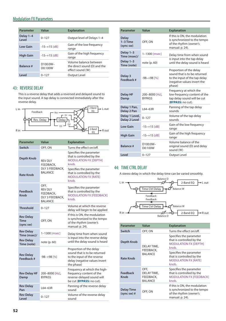
52
Modulation FX Parameters
Parameter Value Explanation
Delay 1–4 Level 0–127 Output level of Delays 1–4
Low Gain -15–+15 [dB] Gain of the low frequency range
High Gain -15–+15 [dB] Gain of the high frequency range
Balance # D100:0W–D0:100W
Volume balance between the direct sound (D) and the effect sound (W)
Level 0–127 Output Level
43: REVERSE DELAYThis is a reverse delay that adds a reversed and delayed sound to the input sound. A tap delay is connected immediately after the reverse delay.
FeedbackL in
R in
Rev. Delay
L out
R out2-BandEQ
2-BandEQ
Rev
DelayD2
D1
D3
Parameter Value Explanation
Switch OFF, ON Turns the effect on/off.
Depth KnobREV DLY FEEDBACK, DLY 3 FEEDBACK, BALANCE
Specifies the parameter that is controlled by the MODULATION FX [DEPTH] knob.
Rate Knob
Specifies the parameter that is controlled by the MODULATION FX [RATE] knob.
Feedback Knob
OFF, REV DLY FEEDBACK, DLY 3 FEEDBACK, BALANCE
Specifies the parameter that is controlled by the MODULATION FX [FEEDBACK] knob.
Threshold 0–127 Volume at which the reverse delay will begin to be applied
Rev Delay Time (sync sw)
OFF, ON
If this is ON, the modulation is synchronized to the tempo of the rhythm (owner’s manual: p. 24).
Rev Delay Time (msec)/
Rev Delay Time (note)
1–1300 [msec] Delay time from when sound is input into the reverse delay until the delay sound is heardnote (p. 60)
Rev Delay Feedback # -98–+98 [%]
Proportion of the delay sound that is to be returned to the input of the reverse delay (negative values invert the phase)
Rev Delay HF Damp
200–8000 [Hz], BYPASS
Frequency at which the high-frequency content of the reverse-delayed sound will be cut (BYPASS: no cut).
Rev Delay Pan L64–63R Panning of the reverse delay
sound
Rev Delay Level 0–127 Volume of the reverse delay
sound
Parameter Value Explanation
Delay 1–3 Time (sync sw)
OFF, ON
If this is ON, the modulation is synchronized to the tempo of the rhythm (owner’s manual: p. 24).
Delay 1–3 Time (msec)/
Delay 1–3 Time (note)
1–1300 [msec] Delay time from when sound is input into the tap delay until the delay sound is heardnote (p. 60)
Delay 3 Feedback # -98–+98 [%]
Proportion of the delay sound that is to be returned to the input of the tap delay (negative values invert the phase)
Delay HF Damp
200–8000 [Hz], BYPASS
Frequency at which the low-frequency content of the tap delay sound will be cut (BYPASS: no cut).
Delay 1 Pan, Delay 2 Pan L64–63R Panning of the tap delay
sounds
Delay 1 Level, Delay 2 Level 0–127 Volume of the tap delay
sounds
Low Gain -15–+15 [dB] Gain of the low frequency range
High Gain -15–+15 [dB] Gain of the high frequency range
Balance # D100:0W–D0:100W
Volume balance of the original sound (D) and delay sound (W)
Level 0–127 Output Level
44: TIME CTRL DELAYA stereo delay in which the delay time can be varied smoothly.
R in R out
L in L out
FeedbackFeedback
Balance W
Balance W
Time Ctrl Delay
Time Ctrl Delay
2-Band EQ
2-Band EQ
Balance D
Balance D
Parameter Value Explanation
Switch OFF, ON Turns the effect on/off.
Depth KnobDELAY TIME, FEEDBACK, BALANCE
Specifies the parameter that is controlled by the MODULATION FX [DEPTH] knob.
Rate Knob
Specifies the parameter that is controlled by the MODULATION FX [RATE] knob.
Feedback Knob
OFF, DELAY TIME, FEEDBACK, BALANCE
Specifies the parameter that is controlled by the MODULATION FX [FEEDBACK] knob.
Delay Time (sync sw) # OFF, ON
If this is ON, the modulation is synchronized to the tempo of the rhythm (owner’s manual: p. 24).

53
Modulation FX Parameters
Parameter Value Explanation
Delay Time (msec) #/
Delay Time (note) #
1–1300 [msec]Adjusts the time until the delay is heard.
note (p. 60)
Acceleration 0–15
Adjusts the speed which the Delay Time changes from the current setting to a specified new setting.
The rate of change for the Delay Time directly affects the rate of pitch change.
Feedback # -98–+98 [%]
Adjusts the amount of the delay sound that’s fed back into the effect. Negative “-” settings invert the phase.
HF Damp 200–8000 [Hz], BYPASS
Adjusts the frequency above which sound fed back to the effect is filtered out (BYPASS: no cut).
Low Gain -15–+15 [dB] Gain of the low frequency range
High Gain -15–+15 [dB] Gain of the high frequency range
Balance # D100:0W–D0:100W
Volume balance between the direct sound (D) and the delay sound (W)
Level 0–127 Output Level
45: LOFI COMPRESSThis is an effect that intentionally degrades the tone quality for creative purposes.
L in
R in
L out
R out
Compressor
Lo-Fi
Lo-Fi
Compressor
2-BandEQ
2-BandEQ
Parameter Value Explanation
Switch OFF, ON Turns the effect on/off.
Depth Knob
BALANCE, LEVEL
Specifies the parameter that is controlled by the MODULATION FX [DEPTH] knob.
Rate Knob
Specifies the parameter that is controlled by the MODULATION FX [RATE] knob.
Feedback Knob
OFF, BALANCE, LEVEL
Specifies the parameter that is controlled by the MODULATION FX [FEEDBACK] knob.
Pre Filter Type 1–6
Selects the type of filter applied to the sound before it passes through the Lo-Fi effect.
1: Compressor off
2–6: Compressor on
LoFi Type 1–9
Degrades the tone quality. The tone quality grows poorer as this value is increased.
Parameter Value Explanation
Post Filter Type OFF, LPF, HPF
Type of filter
OFF: no filter is used
LPF: cuts the frequency range above the Cutoff
HPF: cuts the frequency range below the Cutoff
Post Filter Cutoff 200–8000 [Hz] Basic frequency of the Post
Filter
Low Gain -15–+15 [dB] Gain of the low range
High Gain -15–+15 [dB] Gain of the high range
Balance # D100:0W–D0:100W
Volume balance between the direct sound (D) and the effect sound (W)
Level # 0–127 Output Level
46: BIT CRUSHERThis creates a lo-fi sound.
L in
R in
L out
R out
Bit Crusher
2-Band EQ
2-Band EQ
Bit Crusher
Parameter Value Explanation
Switch OFF, ON Turns the effect on/off.
Depth KnobSAMPLE RATE, BIT DOWN, FILTER
Specifies the parameter that is controlled by the MODULATION FX [DEPTH] knob.
Rate Knob
Specifies the parameter that is controlled by the MODULATION FX [RATE] knob.
Feedback Knob
OFF, SAMPLE RATE, BIT DOWN, FILTER
Specifies the parameter that is controlled by the MODULATION FX [FEEDBACK] knob.
Sample Rate # 0–127 Adjusts the sample rate.
Bit Down # 0–20 Adjusts the bit depth.
Filter # 0–127 Adjusts the filter depth.
Low Gain -15–+15 [dB] Gain of the low frequency range
High Gain -15–+15 [dB] Gain of the high frequency range
Level 0–127 Output Level
47: PITCH SHIFTERA stereo pitch shifter.
L in
R in
Pitch Shifter
Pitch Shifter
L out
R out
2-Band EQ
2-Band EQ
Parameter Value Explanation
Switch OFF, ON Turns the effect on/off.
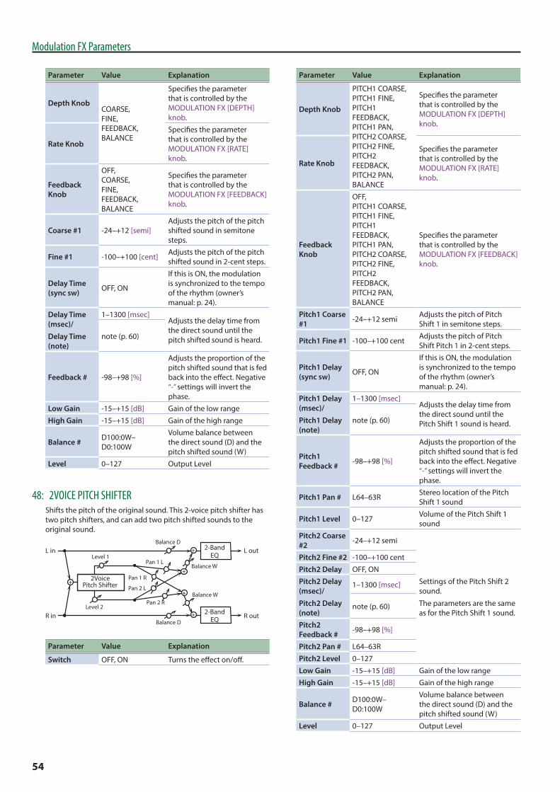
54
Modulation FX Parameters
Parameter Value Explanation
Depth KnobCOARSE, FINE, FEEDBACK, BALANCE
Specifies the parameter that is controlled by the MODULATION FX [DEPTH] knob.
Rate Knob
Specifies the parameter that is controlled by the MODULATION FX [RATE] knob.
Feedback Knob
OFF, COARSE, FINE, FEEDBACK, BALANCE
Specifies the parameter that is controlled by the MODULATION FX [FEEDBACK] knob.
Coarse #1 -24–+12 [semi]Adjusts the pitch of the pitch shifted sound in semitone steps.
Fine #1 -100–+100 [cent] Adjusts the pitch of the pitch shifted sound in 2-cent steps.
Delay Time (sync sw) OFF, ON
If this is ON, the modulation is synchronized to the tempo of the rhythm (owner’s manual: p. 24).
Delay Time (msec)/
Delay Time (note)
1–1300 [msec]Adjusts the delay time from the direct sound until the pitch shifted sound is heard.note (p. 60)
Feedback # -98–+98 [%]
Adjusts the proportion of the pitch shifted sound that is fed back into the effect. Negative “-” settings will invert the phase.
Low Gain -15–+15 [dB] Gain of the low range
High Gain -15–+15 [dB] Gain of the high range
Balance # D100:0W–D0:100W
Volume balance between the direct sound (D) and the pitch shifted sound (W)
Level 0–127 Output Level
48: 2VOICE PITCH SHIFTERShifts the pitch of the original sound. This 2-voice pitch shifter has two pitch shifters, and can add two pitch shifted sounds to the original sound.
L in
R in
L out
R out
Level 1
Balance W
Balance D
Balance W
Balance D
Level 2Pan 2 R
Pan 1 L
Pan 1 R
Pan 2 L
2VoicePitch Shifter
2-BandEQ
2-BandEQ
Parameter Value Explanation
Switch OFF, ON Turns the effect on/off.
Parameter Value Explanation
Depth Knob
PITCH1 COARSE, PITCH1 FINE, PITCH1 FEEDBACK, PITCH1 PAN, PITCH2 COARSE, PITCH2 FINE, PITCH2 FEEDBACK, PITCH2 PAN, BALANCE
Specifies the parameter that is controlled by the MODULATION FX [DEPTH] knob.
Rate Knob
Specifies the parameter that is controlled by the MODULATION FX [RATE] knob.
Feedback Knob
OFF, PITCH1 COARSE, PITCH1 FINE, PITCH1 FEEDBACK, PITCH1 PAN, PITCH2 COARSE, PITCH2 FINE, PITCH2 FEEDBACK, PITCH2 PAN, BALANCE
Specifies the parameter that is controlled by the MODULATION FX [FEEDBACK] knob.
Pitch1 Coarse #1 -24–+12 semi Adjusts the pitch of Pitch
Shift 1 in semitone steps.
Pitch1 Fine #1 -100–+100 cent Adjusts the pitch of Pitch Shift Pitch 1 in 2-cent steps.
Pitch1 Delay (sync sw) OFF, ON
If this is ON, the modulation is synchronized to the tempo of the rhythm (owner’s manual: p. 24).
Pitch1 Delay (msec)/
Pitch1 Delay (note)
1–1300 [msec]Adjusts the delay time from the direct sound until the Pitch Shift 1 sound is heard.note (p. 60)
Pitch1 Feedback # -98–+98 [%]
Adjusts the proportion of the pitch shifted sound that is fed back into the effect. Negative “-” settings will invert the phase.
Pitch1 Pan # L64–63R Stereo location of the Pitch Shift 1 sound
Pitch1 Level 0–127 Volume of the Pitch Shift 1 sound
Pitch2 Coarse #2 -24–+12 semi
Settings of the Pitch Shift 2 sound.
The parameters are the same as for the Pitch Shift 1 sound.
Pitch2 Fine #2 -100–+100 cent
Pitch2 Delay OFF, ON
Pitch2 Delay (msec)/
Pitch2 Delay (note)
1–1300 [msec]
note (p. 60)
Pitch2 Feedback # -98–+98 [%]
Pitch2 Pan # L64–63R
Pitch2 Level 0–127
Low Gain -15–+15 [dB] Gain of the low range
High Gain -15–+15 [dB] Gain of the high range
Balance # D100:0W–D0:100W
Volume balance between the direct sound (D) and the pitch shifted sound (W)
Level 0–127 Output Level

55
Modulation FX Parameters
49: OD 0 CHORUSL in
R in
ChorusOverdrive
L out
R out
Balance W
Balance W
Balance D
Balance D
Parameter Value Explanation
Switch OFF, ON Turns the effect on/off.
Depth Knob OVERDRIVE DRIVE, OVERDRIVE PAN, CHORUS RATE, CHORUS BALANCE
Specifies the parameter that is controlled by the MODULATION FX [DEPTH] knob.
Rate Knob
Specifies the parameter that is controlled by the MODULATION FX [RATE] knob.
Feedback Knob
OFF, OVERDRIVE DRIVE, OVERDRIVE PAN, CHORUS RATE, CHORUS BALANCE
Specifies the parameter that is controlled by the MODULATION FX [FEEDBACK] knob.
Overdrive Drive # 0–127
Degree of distortion
Also changes the volume.
Overdrive Pan # L64–63R Stereo location of the
overdrive sound
Chorus Pre Delay 0.0–100.0 [msec]
Adjusts the delay time from the direct sound until the chorus sound is heard.
Chorus Rate (sync sw) OFF, ON
If this is ON, the modulation is synchronized to the tempo of the rhythm (owner’s manual: p. 24).
Chorus Rate (Hz) #/
Chorus Rate (note) #
0.05–10.00 [Hz]
Frequency of modulationnote (p. 60)
Chorus Depth 0–127 Depth of modulation
Chorus Balance #
D100:0W–D0:100W
Adjusts the volume balance between the sound that is sent through the chorus (W) and the sound that is not sent through the chorus (D).
Level 0–127 Output Level
50: OD 0 FLANGER
L in
R in
FlangerOverdrive
L out
R out
Balance W
Balance W
Balance D
Balance D
Feedback
Parameter Value Explanation
Switch OFF, ON Turns the effect on/off.
Parameter Value Explanation
Depth Knob OVERDRIVE DRIVE, OVERDRIVE PAN, FLN RATE, FLN FEEDBACK, FLN BALANCE
Specifies the parameter that is controlled by the MODULATION FX [DEPTH] knob.
Rate Knob
Specifies the parameter that is controlled by the MODULATION FX [RATE] knob.
Feedback Knob
OFF, OVERDRIVE DRIVE, OVERDRIVE PAN, FLN RATE, FLN FEEDBACK, FLN BALANCE
Specifies the parameter that is controlled by the MODULATION FX [FEEDBACK] knob.
Overdrive Drive # 0–127
Degree of distortion
Also changes the volume.
Overdrive Pan # L64–63R Stereo location of the
overdrive sound
Flanger Pre Delay 0.0–100 [msec]
Adjusts the delay time from the direct sound until the flanger sound is heard.
Flanger Rate (sync sw) OFF, ON
If this is ON, the modulation is synchronized to the tempo of the rhythm (owner’s manual: p. 24).
Flanger Rate (Hz) #/
Flanger Rate (note) #
0.05–10.00 [Hz]
Frequency of modulationnote (p. 60)
Flanger Depth 0–127 Depth of modulation
Flanger Feedback # -98–+98 [%]
Adjusts the proportion of the flanger sound that is fed back into the effect. Negative “-” settings will invert the phase.
Flanger Balance #
D100:0W–D0:100W
Adjusts the volume balance between the sound that is sent through the flanger (W) and the sound that is not sent through the flanger (D).
Level 0–127 Output Level
51: OD 0 DELAYL in
R in
DelayOverdrive
L out
R out
Balance W
Balance W
Balance D
Balance D
Feedback
Parameter Value Explanation
Switch OFF, ON Turns the effect on/off.
Depth KnobOVERDRIVE DRIVE, OVERDRIVE PAN, DELAY FEEDBACK, DELAY BALANCE
Specifies the parameter that is controlled by the MODULATION FX [DEPTH] knob.
Rate Knob
Specifies the parameter that is controlled by the MODULATION FX [RATE] knob.

56
Modulation FX Parameters
Parameter Value Explanation
Feedback Knob
OFF, OVERDRIVE DRIVE, OVERDRIVE PAN, DELAY FEEDBACK, DELAY BALANCE
Specifies the parameter that is controlled by the MODULATION FX [FEEDBACK] knob.
Overdrive Drive # 0–127
Degree of distortion
Also changes the volume.
Overdrive Pan # L64–63R Stereo location of the
overdrive sound
Delay Time (sync sw) OFF, ON
If this is ON, the modulation is synchronized to the tempo of the rhythm (owner’s manual: p. 24).
Delay Time (msec)/
Delay Time (note)
1–2600 [msec] Adjusts the delay time from the direct sound until the delay sound is heard.note (p. 60)
Delay Feedback # -98–+98 [%]
Adjusts the proportion of the delay sound that is fed back into the effect. Negative “-” settings will invert the phase.
Delay HF Damp
200–8000 [Hz], BYPASS
Adjusts the frequency above which sound fed back to the effect will be cut (BYPASS: no cut).
Delay Balance #
D100:0W–D0:100W
Adjusts the volume balance between the sound that is sent through the delay (W) and the sound that is not sent through the delay (D).
Level 0–127 Output Level
52: DS 0 CHORUSThe parameters are essentially the same as in “49: OD 0 CHORUS,” with the exception of the following two.
5 Overdrive Drive 0 Distortion Drive
5 Overdrive Pan 0 Distortion Pan
L in
R in
ChorusDistortion
L out
R out
Balance W
Balance W
Balance D
Balance D
53: DS 0 FLANGERThe parameters are essentially the same as in “50: OD 0 FLANGER,” with the exception of the following two.
5 Overdrive Drive 0 Distortion Drive
5 Overdrive Pan 0 Distortion Pan
L in
R in
FlangerDistortion
L out
R out
Balance W
Balance W
Balance D
Balance D
Feedback
54: DS 0 DELAYThe parameters are essentially the same as in “51: OD 0 DELAY,” with the exception of the following two.
5 Overdrive Drive 0 Distortion Drive
5 Overdrive Pan 0 Distortion Pan
L in
R in
DelayDistortion
L out
R out
Balance W
Balance W
Balance D
Balance D
Feedback
55: OD/DS 0 TWAH
Amp Simulator
2-BandEQ
L in
R in
Overdrive/Distortion
L out
R out
Touch Wah
Parameter Value Explanation
Switch OFF, ON Turns the effect on/off.
Depth Knob DRIVE, TONE, TWAH SENS, TWAH MANUAL, TWAH PEAK, TWAH BALANCE
Specifies the parameter that is controlled by the MODULATION FX [DEPTH] knob.
Rate Knob
Specifies the parameter that is controlled by the MODULATION FX [RATE] knob.
Feedback Knob
OFF, DRIVE, TONE, TWAH SENS, TWAH MANUAL, TWAH PEAK, TWAH BALANCE
Specifies the parameter that is controlled by the MODULATION FX [FEEDBACK] knob.
Drive Switch OFF, ON Turns overdrive/distortion on/off
Drive Type OVERDRIVE, DISTORTION Type of distortion
Drive # 0–127Degree of distortion
Also changes the volume.
Tone # 0–127 Sound quality of the Overdrive effect
Amp Switch OFF, ON Turns the Amp Simulator on/off.
Amp Type
SMALL, BUILT-IN, 2-STACK, 3-STACK
Type of guitar amp
SMALL: small amp BUILT-IN: single-unit type amp 2-STACK: large double stack amp 3-STACK: large triple stack amp
TWah Switch OFF, ON Wah on/off
TWah Filter Type LPF, BPF
Type of filter LPF: Produces a wah effect in a broad frequency range. BPF: Produces a wah effect in a narrow frequency range.

57
Modulation FX Parameters
Parameter Value Explanation
TWah Polarity DOWN, UP
Direction in which the filter will move UP: Move toward a higher frequency DOWN: Move toward a lower frequency
TWah Sens # 0–127 Sensitivity with which the filter is modified
TWah Manual # 0–127 Basic frequency at which the
wah effect is applied
TWah Peak # 0–127
Width of the frequency region at which the wah effect is applied Increasing this value will make the frequency region narrower.
TWah Balance #
D100:0W–D0:100W
Volume balance of the sound that passes through the wah (W) and the direct sound (D)
Low Gain -15–+15 [dB] Gain of the low range
High Gain -15–+15 [dB] Gain of the high range
Level 0–127 Output Level
56: OD/DS 0 AWAH
Amp Simulator
2-BandEQ
L in
R in
Overdrive/Distortion
L out
R out
Auto Wah
Parameter Value Explanation
Switch OFF, ON Turns the effect on/off.
Depth Knob
DRIVE, TONE, AUTOWAH MANUAL, AUTOWAH PEAK, AUTOWAH RATE, AUTOWAH DEPTH, AUTOWAH BALANCE
Specifies the parameter that is controlled by the MODULATION FX [DEPTH] knob.
Rate Knob
Specifies the parameter that is controlled by the MODULATION FX [RATE] knob.
Feedback Knob
OFF, DRIVE, TONE, AUTOWAH MANUAL, AUTOWAH PEAK, AUTOWAH RATE, AUTOWAH DEPTH, AUTOWAH BALANCE
Specifies the parameter that is controlled by the MODULATION FX [FEEDBACK] knob.
Drive Switch OFF, ON Overdrive/distortion on/off
Drive Type OVERDRIVE, DISTORTION Type of distortion
Drive # 0–127Degree of distortion
Also changes the volume.
Tone # 0–127 Sound quality of the Overdrive effect
Amp Switch OFF, ON Turns the Amp Simulator on/off.
Parameter Value Explanation
Amp Type
SMALL, BUILT-IN, 2-STACK, 3-STACK
Type of guitar amp
SMALL: small amp BUILT-IN: single-unit type amp 2-STACK: large double stack amp 3-STACK: large triple stack amp
AutoWah Switch OFF, ON Wah on/off
AutoWah Filter Type LPF, BPF
Type of filter
LPF: Produces a wah effect in a broad frequency range. BPF: Produces a wah effect in a narrow frequency range.
AutoWah Manual # 0–127 Basic frequency at which the
wah effect is applied
AutoWah Peak # 0–127
Width of the frequency region at which the wah effect is applied
Increasing this value will make the frequency region narrower.
AutoWah Rate (sync sw)
OFF, ON
If this is ON, the modulation is synchronized to the tempo of the rhythm (owner’s manual: p. 24).
AutoWah Rate (Hz) #/
AutoWah Rate (note) #
0.05–10.00 [Hz]Rate at which the wah effect is modulatednote (p. 60)
AutoWah Depth # 0–127 Depth at which the wah
effect is modulated
AutoWah Balance #
D100:0W–D0:100W
Volume balance of the sound that passes through the wah (W) and the direct sound (D)
Low Gain -15–+15 [dB] Gain of the low range
High Gain -15–+15 [dB] Gain of the high range
Level 0–127 Output Level
57: ENHANCER 0 CHORUS
Chorus
L in
R in
L out
R out
Mix
Mix
Enhancer
Enhancer
Balance W
Balance W
Balance D
Balance D
Parameter Value Explanation
Switch OFF, ON Turns the effect on/off.
Depth Knob ENHANCER SENS, ENHANCER MIX, CHORUS RATE, CHORUS BALANCE
Specifies the parameter that is controlled by the MODULATION FX [DEPTH] knob.
Rate Knob
Specifies the parameter that is controlled by the MODULATION FX [RATE] knob.

58
Modulation FX Parameters
Parameter Value Explanation
Feedback Knob
OFF, ENHANCER SENS, ENHANCER MIX, CHORUS RATE, CHORUS BALANCE
Specifies the parameter that is controlled by the MODULATION FX [FEEDBACK] knob.
Enhancer Sens # 0–127 Sensitivity of the enhancer
Enhancer Mix # 0–127 Level of the overtones
generated by the enhancer
Chorus Pre Delay 0.0–100 [msec]
Adjusts the delay time from the direct sound until the chorus sound is heard.
Chorus Rate (sync sw) OFF, ON
If this is ON, the modulation is synchronized to the tempo of the rhythm (owner’s manual: p. 24).
Chorus Rate (Hz) #/
Chorus Rate (note) #
0.05–10.00 [Hz]
Frequency of modulationnote (p. 60)
Chorus Depth 0–127 Depth of modulation
Chorus Balance #
D100:0W–D0:100W
Adjusts the volume balance between the sound that is sent through the chorus (W) and the sound that is not sent through the chorus (D).
Level 0–127 Output Level
58: ENHANCER 0 FLANGER
Feedback
Flanger
L in
R in
L out
R out
Mix
Mix
Enhancer
Enhancer
Balance W
Balance W
Balance D
Balance D
Parameter Value Explanation
Switch OFF, ON Turns the effect on/off.
Depth Knob ENHANCER SENS, ENHANCER MIX, FLN RATE, FLN FEEDBACK, FLN BALANCE
Specifies the parameter that is controlled by the MODULATION FX [DEPTH] knob.
Rate Knob
Specifies the parameter that is controlled by the MODULATION FX [RATE] knob.
Feedback Knob
OFF, ENHANCER SENS, ENHANCER MIX, FLN RATE, FLN FEEDBACK, FLN BALANCE
Specifies the parameter that is controlled by the MODULATION FX [FEEDBACK] knob.
Enhancer Sens # 0–127 Sensitivity of the enhancer
Enhancer Mix # 0–127 Level of the overtones
generated by the enhancer
Flanger Pre Delay 0.0–100 [msec]
Adjusts the delay time from the direct sound until the flanger sound is heard.
Parameter Value Explanation
Flanger Rate (sync sw) OFF, ON
If this is ON, the modulation is synchronized to the tempo of the rhythm (owner’s manual: p. 24).
Flanger Rate (Hz) #
Flanger Rate (note) #
0.05–10.0 [Hz]Frequency of modulation
note (p. 60)
Flanger Depth 0–127 Depth of modulation
Flanger Feedback # -98–+98 [%]
Adjusts the proportion of the flanger sound that is fed back into the effect. Negative “-” settings will invert the phase.
Flanger Balance #
D100:0W–D0:100W
Adjusts the volume balance between the sound that is sent through the flanger (W) and the sound that is not sent through the flanger (D).
Level 0–127 Output Level
59: ENHANCER 0 DELAY
Feedback
Delay
L in
R in
L out
R out
Mix
Mix
Enhancer
Enhancer
Balance W
Balance W
Balance D
Balance D
Parameter Value Explanation
Switch OFF, ON Turns the effect on/off.
Depth KnobENHANCER SENS, ENHANCER MIX, DELAY FEEDBACK, DELAY BALANCE
Specifies the parameter that is controlled by the MODULATION FX [DEPTH] knob.
Rate Knob
Specifies the parameter that is controlled by the MODULATION FX [RATE] knob.
Feedback Knob
OFF, ENHANCER SENS, ENHANCER MIX, DELAY FEEDBACK, DELAY BALANCE
Specifies the parameter that is controlled by the MODULATION FX [FEEDBACK] knob.
Enhancer Sens # 0–127 Sensitivity of the enhancer
Enhancer Mix # 0–127 Level of the overtones
generated by the enhancer
Delay Time (sync sw) OFF, ON
If this is ON, the modulation is synchronized to the tempo of the rhythm (owner’s manual: p. 24).
Delay Time (msec)/
Delay Time (note)
1–2600 [msec] Adjusts the delay time from the direct sound until the delay sound is heard.note (p. 60)
Delay Feedback # -98–+98 [%]
Adjusts the proportion of the delay sound that is fed back into the effect. Negative “-” settings will invert the phase.
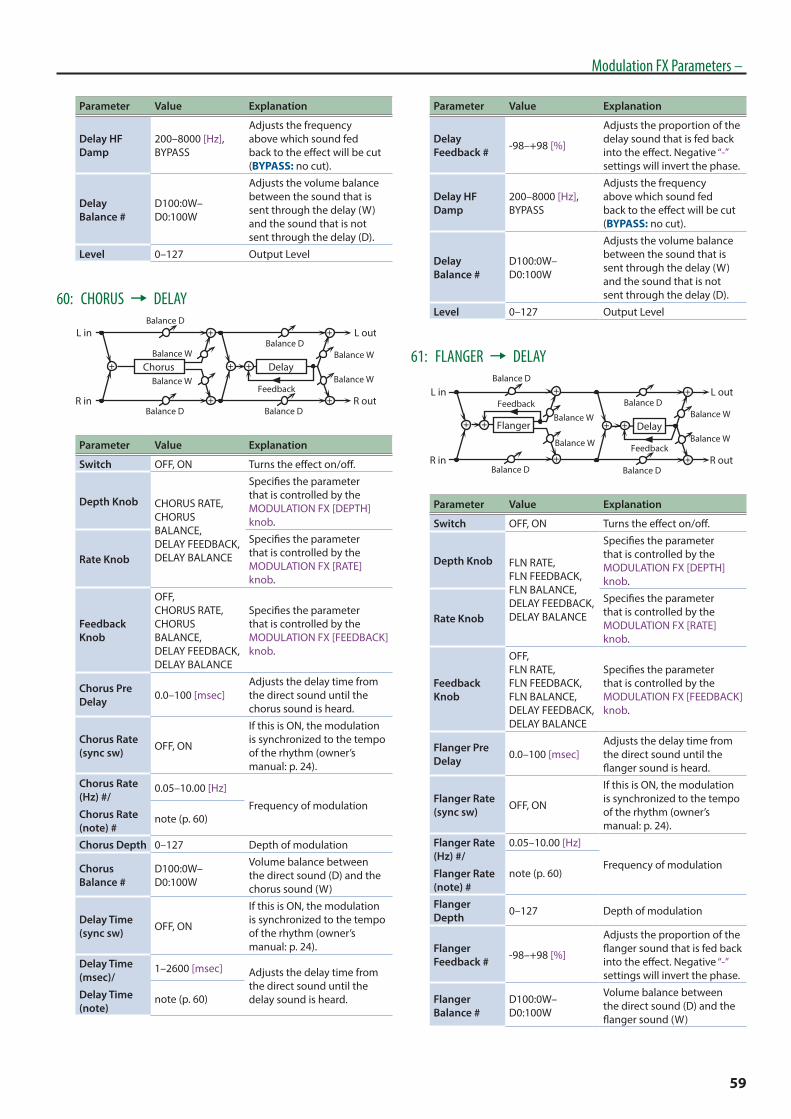
59
Modulation FX Parameters –
Parameter Value Explanation
Delay HF Damp
200–8000 [Hz], BYPASS
Adjusts the frequency above which sound fed back to the effect will be cut (BYPASS: no cut).
Delay Balance #
D100:0W–D0:100W
Adjusts the volume balance between the sound that is sent through the delay (W) and the sound that is not sent through the delay (D).
Level 0–127 Output Level
60: CHORUS 0 DELAY
Feedback
Delay
L in
R in
L out
R out
Balance W
Balance W
Balance D
Balance D
ChorusBalance W
Balance W
Balance D
Balance D
Parameter Value Explanation
Switch OFF, ON Turns the effect on/off.
Depth Knob CHORUS RATE, CHORUS BALANCE, DELAY FEEDBACK, DELAY BALANCE
Specifies the parameter that is controlled by the MODULATION FX [DEPTH] knob.
Rate Knob
Specifies the parameter that is controlled by the MODULATION FX [RATE] knob.
Feedback Knob
OFF, CHORUS RATE, CHORUS BALANCE, DELAY FEEDBACK, DELAY BALANCE
Specifies the parameter that is controlled by the MODULATION FX [FEEDBACK] knob.
Chorus Pre Delay 0.0–100 [msec]
Adjusts the delay time from the direct sound until the chorus sound is heard.
Chorus Rate (sync sw) OFF, ON
If this is ON, the modulation is synchronized to the tempo of the rhythm (owner’s manual: p. 24).
Chorus Rate (Hz) #/
Chorus Rate (note) #
0.05–10.00 [Hz]
Frequency of modulationnote (p. 60)
Chorus Depth 0–127 Depth of modulation
Chorus Balance #
D100:0W–D0:100W
Volume balance between the direct sound (D) and the chorus sound (W)
Delay Time (sync sw) OFF, ON
If this is ON, the modulation is synchronized to the tempo of the rhythm (owner’s manual: p. 24).
Delay Time (msec)/
Delay Time (note)
1–2600 [msec] Adjusts the delay time from the direct sound until the delay sound is heard.note (p. 60)
Parameter Value Explanation
Delay Feedback # -98–+98 [%]
Adjusts the proportion of the delay sound that is fed back into the effect. Negative “-” settings will invert the phase.
Delay HF Damp
200–8000 [Hz], BYPASS
Adjusts the frequency above which sound fed back to the effect will be cut (BYPASS: no cut).
Delay Balance #
D100:0W–D0:100W
Adjusts the volume balance between the sound that is sent through the delay (W) and the sound that is not sent through the delay (D).
Level 0–127 Output Level
61: FLANGER 0 DELAY
Feedback
Delay
L in
R in
L out
R out
Balance W
Balance W
Balance D
Balance D
Flanger
Balance W
Balance W
Balance D
Balance D
Feedback
Parameter Value Explanation
Switch OFF, ON Turns the effect on/off.
Depth Knob FLN RATE, FLN FEEDBACK, FLN BALANCE, DELAY FEEDBACK, DELAY BALANCE
Specifies the parameter that is controlled by the MODULATION FX [DEPTH] knob.
Rate Knob
Specifies the parameter that is controlled by the MODULATION FX [RATE] knob.
Feedback Knob
OFF, FLN RATE, FLN FEEDBACK, FLN BALANCE, DELAY FEEDBACK, DELAY BALANCE
Specifies the parameter that is controlled by the MODULATION FX [FEEDBACK] knob.
Flanger Pre Delay 0.0–100 [msec]
Adjusts the delay time from the direct sound until the flanger sound is heard.
Flanger Rate (sync sw) OFF, ON
If this is ON, the modulation is synchronized to the tempo of the rhythm (owner’s manual: p. 24).
Flanger Rate (Hz) #/
Flanger Rate (note) #
0.05–10.00 [Hz]
Frequency of modulationnote (p. 60)
Flanger Depth 0–127 Depth of modulation
Flanger Feedback # -98–+98 [%]
Adjusts the proportion of the flanger sound that is fed back into the effect. Negative “-” settings will invert the phase.
Flanger Balance #
D100:0W–D0:100W
Volume balance between the direct sound (D) and the flanger sound (W)

60
Modulation FX Parameters –
Parameter Value Explanation
Delay Time (sync sw) OFF, ON
If this is ON, the modulation is synchronized to the tempo of the rhythm (owner’s manual: p. 24).
Delay Time (msec)/
Delay Time (note)
1–2600 [msec]Adjusts the delay time from the direct sound until the delay sound is heard.note (p. 60)
Delay Feedback # -98–+98 [%]
Adjusts the proportion of the delay sound that is fed back into the effect. Negative “-” settings will invert the phase.
Delay HF Damp
200–8000 [Hz], BYPASS
Adjusts the frequency above which sound fed back to the effect will be cut (BYPASS: no cut).
Delay Balance #
D100:0W–D0:100W
Adjusts the volume balance between the sound that is sent through the delay (W) and the sound that is not sent through the delay (D).
Level 0–127 Output Level
62: CHORUS 0 FLANGER
Feedback
Flanger
L in
R in
L out
R out
Balance W
Balance W
Balance D
Balance D
ChorusBalance W
Balance W
Balance D
Balance D
a
Parameter Value Explanation
Switch OFF, ON Turns the effect on/off.
Depth Knob CHORUS RATE, CHORUS BALANCE, FLN RATE, FLN FEEDBACK, FLN BALANCE
Specifies the parameter that is controlled by the MODULATION FX [DEPTH] knob.
Rate Knob
Specifies the parameter that is controlled by the MODULATION FX [RATE] knob.
Feedback Knob
OFF, CHORUS RATE, CHORUS BALANCE, FLN RATE, FLN FEEDBACK, FLN BALANCE
Specifies the parameter that is controlled by the MODULATION FX [FEEDBACK] knob.
Chorus Pre Delay 0.0–100 [msec]
Adjusts the delay time from the direct sound until the chorus sound is heard.
Chorus Rate (sync sw) OFF, ON
If this is ON, the modulation is synchronized to the tempo of the rhythm (owner’s manual: p. 24).
Chorus Rate (Hz) #/
Chorus Rate (note) #
0.05–10.00 [Hz]Modulation frequency of the chorus effectnote (p. 60)
Chorus Depth 0–127 Modulation depth of the chorus effect
Parameter Value Explanation
Chorus Balance #
D100:0W–D0:100W
Volume balance between the direct sound (D) and the chorus sound (W)
Flanger Pre Delay 0.0–100 [msec]
Adjusts the delay time from the direct sound until the flanger sound is heard.
Flanger Rate (sync sw) OFF, ON
If this is ON, the modulation is synchronized to the tempo of the rhythm (owner’s manual: p. 24).
Flanger Rate (Hz) #/
Flanger Rate (note) #
0.05–10.00 [Hz]Modulation frequency of the flanger effectnote (p. 60)
Flanger Depth 0–127 Modulation depth of the
flanger effect
Flanger Feedback # -98–+98 [%]
Adjusts the proportion of the flanger sound that is fed back into the effect. Negative “-” settings will invert the phase.
Flanger Balance #
D100:0W–D0:100W
Adjusts the volume balance between the sound that is sent through the flanger (W) and the sound that is not sent through the flanger (D).
Level 0–127 Output Level
Note
Double note
Dotted whole note
Dotted half note
Dotted thirty-second note
Whole note Double-note triplet
Sixteenth-note tripletThirty-second note
Sixty-fourth-note triplet Sixty-fourth note Thirty-second-note triplet
Dotted eighth noteQuarter-note tripletEighth note
Half-note tripletQuarter note Dotted quarter note
Whole-note tripletHalf note
Sixteenth note Eighth-note triplet Dotted sixteenth note

61
The Tremolo/Amp Simulator effect is included in the tone.
You can choose from six types of tremolo and amp simulator that are optimized in different ways.
Tremolo/Amp Simulator Parameters
1: NORMAL
L in
R in
L out
R out
Overdrive
Tremolo
Tremolo
Overdrive
2-BandEQ
2-BandEQ
Parameter Value Explanation
OD Switch OFF, ON Overdrive on/off
OD Drive 0–127 Degree of distortion
Tremolo Switch OFF, ON Tremolo on/off
Tremolo Mod Wave
TRI, SQR, SIN, SAW1, SAW2, TRP
Modulation Wave
TRI: triangle wave
SQR: square wave
SIN: sine wave
SAW1/2: sawtooth wave
TRP: Trapezoidal wave
Tremolo Rate (sync sw) OFF, ON
If this is ON, the modulation is synchronized to the tempo of the rhythm (owner’s manual: p. 24).
Tremolo Rate (Hz)/
Tremolo Rate (note)
0.05–10.00 [Hz]
Rate of the tremolo effectnote (p. 60)
Tremolo Depth 0–127 Depth of the tremolo effect
Low Gain -15–+15 [dB] Gain of the low range
High Gain -15–+15 [dB] Gain of the high range
Level 0–127 Output Level
2: A.PIANO
L in
R in
L out
R out
Overdrive
Overdrive
2-BandEQ
2-BandEQ
TremoloLid
TremoloLid
Parameter Value Explanation
Lid 1–7
Amount by which the lid of the grand piano is open.
Higher settings open the lid more, producing a brighter sound.
OD Switch OFF, ON Overdrive on/off
OD Drive 0–127 Degree of distortion
Tremolo Switch OFF, ON Tremolo on/off
Tremolo Mod Wave
TRI, SQR, SIN, SAW1, SAW2, TRP
Modulation Wave
TRI: triangle wave
SQR: square wave
SIN: sine wave
SAW1/2: sawtooth wave
TRP: Trapezoidal wave
Parameter Value Explanation
Tremolo Rate (sync sw) OFF, ON
If this is ON, the modulation is synchronized to the tempo of the rhythm (owner’s manual: p. 24).
Tremolo Rate (Hz)/
Tremolo Rate (note)
0.05–10.00 [Hz]
Rate of the tremolo effectnote (p. 60)
Tremolo Depth 0–127 Depth of the tremolo effect
Low Gain -15–+15 [dB] Gain of the low range
High Gain -15–+15 [dB] Gain of the high range
Level 0–127 Output Level
3: E. PIANO
Overdrive Tremolo
L in
R in
2-BandEQ
L out
R out
Speaker
Parameter Value Explanation
Bass -50–+50 Gain of the low range
Treble -50–+50 Gain of the high range
Tremolo Switch OFF, ON Tremolo on/off
Tremolo Type
OLDCASE MONO, OLDCASE STEREO, NEWCASE, DYNO, WURLY
Type of tremolo effect
Tremolo Speed (sync sw)
OFF, ON
If this is ON, the modulation is synchronized to the tempo of the rhythm (owner’s manual: p. 24).
Tremolo Speed (Hz)/
Tremolo Speed (note)
0.05–10.00 [Hz]
Rate of the tremolo effectnote (p. 60)
Tremolo Depth 0–127 Depth of the tremolo effect
Tremolo Shape 0–20 Adjusts the waveform of the
tremolo.
AMP Switch OFF, ON If this is off, speaker and overdrive are not applied.
Speaker Type
LINE, OLD, NEW, WURLY, TWIN
Type of speaker
* If LINE is selected, the sound will not be sent through the speaker simulation.
OD Drive 0–127 Degree of distortion
Level 0–127 Output Level
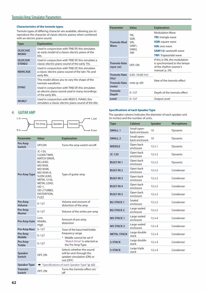
62
Tremolo/Amp Simulator Parameters
Characteristics of the tremolo typesTremolo types of differing character are available, allowing you to reproduce the character of classic electric pianos when combined with an electric piano sound.
Type Explanation
OLDCASE MONO
Used in conjunction with TINE EP, this simulates an early model of a classic electric piano of the 60s.
OLDCASE STEREO
Used in conjunction with TINE EP, this simulates a classic electric piano sound of the early 70s.
NEWCASEUsed in conjunction with TINE EP, this simulates a classic electric piano sound of the late 70s and early 80s.
DYNO
This model allows you to vary the shape of the tremolo waveform.
Used in conjunction with TINE EP, this simulates an electric piano sound used in many recordings of the early 80s.
WURLY Used in conjunction with REED E. PIANO, this simulates a classic electric piano sound of the 60s.
4: GUITAR AMP
Pre Amp Tremolo
L in
R in
L out
R out
Speaker
Parameter Value Explanation
Pre Amp Switch OFF,ON Turns the amp switch on/off.
Pre Amp Type
JC-120, CLEAN TWIN, MATCH DRIVE, BG LEAD, MS1959I, MS1959II, MS1959I+II, SLDN LEAD, METAL 5150, METAL LEAD, OD-1, OD-2 TURBO, DISTORTION, FUZZ
Type of guitar amp
Pre Amp Volume 0–127 Volume and amount of
distortion of the amp
Pre Amp Master 0–127 Volume of the entire pre-amp
Pre Amp GainLow, Middle, High
Amount of pre-amp distortion
Pre Amp Bass 0–127 Tone of the bass/mid/treble frequency range
* Middle cannot be set if “Match Drive” is selected as the Pre Amp Type.
Pre Amp Middle 0–127
Pre Amp Treble 0–127
Speaker Switch OFF, ON
Selects whether the sound will be sent through the speaker simulation (ON) or not (OFF)
Speaker Type & “Specifications of each Speaker Type” (p. 62)
Tremolo Switch OFF, ON Turns the tremolo effect on/
off
Parameter Value Explanation
Tremolo Mod Wave
TRI, SQR, SIN, SAW1, SAW2, TRP
Modulation Wave
TRI: triangle wave
SQR: square wave
SIN: sine wave
SAW1/2: sawtooth wave
TRP: Trapezoidal wave
Tremolo Rate (sync sw) OFF, ON
If this is ON, the modulation is synchronized to the tempo of the rhythm (owner’s manual: p. 24).
Tremolo Rate (Hz)/
Tremolo Rate (note)
0.05–10.00 [Hz]
Rate of the tremolo effectnote (p. 60)
Tremolo Depth 0–127 Depth of the tremolo effect
Level 0–127 Output Level
Specifications of each Speaker TypeThe speaker column indicates the diameter of each speaker unit (in inches) and the number of units.
Type Cabinet Speaker Microphone
SMALL 1 Small open-back enclosure 10 Dynamic
SMALL 2 Small open-back enclosure 10 Dynamic
MIDDLE Open back enclosure 12 x 1 Dynamic
JC-120 Open back enclosure 12 x 2 Dynamic
BUILT-IN 1 Open back enclosure 12 x 2 Dynamic
BUILT-IN 2 Open back enclosure 12 x 2 Condenser
BUILT-IN 3 Open back enclosure 12 x 2 Condenser
BUILT-IN 4 Open back enclosure 12 x 2 Condenser
BUILT-IN 5 Open back enclosure 12 x 2 Condenser
BG STACK 1 Sealed enclosure 12 x 2 Condenser
BG STACK 2 Large sealed enclosure 12 x 2 Condenser
MS STACK 1 Large sealed enclosure 12 x 4 Condenser
MS STACK 2 Large sealed enclosure 12 x 4 Condenser
METAL STACK Large double stack 12 x 4 Condenser
2-STACK Large double stack 12 x 4 Condenser
3-STACK Large triple stack 12 x 4 Condenser

63
Tremolo/Amp Simulator Parameters
5: ROTARY
Overdrive Rotary
L in
R in
L out
R out
Parameter Value Explanation
Speed SLOW, FAST
Simultaneously switch the rotational speed of the low frequency rotor and high frequency rotor.
SLOW: Slows down the rotation to the Slow Rate.
FAST: Speeds up the rotation to the Fast Rate.
Rotary Switch OFF, ON
Switches the rotation of the rotary speaker.
When this is turned off, the rotation will gradually stop.
When it is turned on, the rotation will gradually resume.
Woofer Slow Speed 0.05–10.00 [Hz] Slow speed (SLOW) of the
low frequency rotor
Woofer Fast Speed 0.05–10.00 [Hz] Fast speed (FAST) of the low
frequency rotor
Woofer Trans Up 0–127
Adjusts the rate at which the woofer rotation speeds up when the rotation is switched from Slow to Fast.
Woofer Trans Down 0–127
Adjusts the rate at which the woofer rotation speeds up when the rotation is switched from Fast to Slow.
Woofer Level 0–127 Volume of the woofer
Tweeter Slow Speed 0.05–10.00 [Hz]
Settings of the tweeter
The parameters are the same as for the woofer.
Tweeter Fast Speed 0.05 - 10.00 [Hz]
Tweeter Trans Up 0–127
Tweeter Trans Down 0–127
Tweeter Level 0–127
Spread 0–10
Sets the rotary speaker stereo image.
The higher the value set, the wider the sound is spread out.
Low Gain -15–+15 [dB] Gain of the low range
High Gain -15–+15 [dB] Gain of the high range
Level 0–127 Output Level
OD Switch OFF, ON Overdrive on/off
OD Gain 0–127Overdrive input level Higher values will increase the distortion.
OD Drive 0–127 Degree of distortion
OD Level 0–127 Volume of the overdrive
6: MKS-20 Tremolo
L in
R in
L out
R out
Overdrive
Tremolo
Tremolo
Overdrive
2-BandEQ
2-BandEQ
Parameter Value Explanation
OD Switch OFF, ON Overdrive on/off
OD Drive 0–127 Degree of distortion
Tremolo Switch OFF, ON Turns the tremolo effect on/
off
Tremolo Rate (sync sw) OFF, ON
If this is ON, the modulation is synchronized to the tempo of the rhythm (owner’s manual: p. 24).
Tremolo Rate (Hz)/
Tremolo Rate (note)
0.05–10.00 [Hz]
Rate of the tremolo effectnote (p. 60)
Tremolo Depth 0–15 Depth of the tremolo effect
Low Gain -15–+15 [dB] Gain of the low range
High Gain -15–+15 [dB] Gain of the high range
Level 0–127 Output Level

64
Sympathetic Resonance Parameters
Parameter Value Explanation
Switch OFF, ON When set to ON, the effect is applied.
Depth 0–127 Depth of the effect
Damper 0–127Depth to which the damper pedal is pressed (controls the resonant sound)
Pre LPF 16–15000 [Hz], BYPASS
Frequency of the filter that cuts the high-frequency content of the input sound (BYPASS: no cut)
Pre HPF BYPASS, 16–15000 [Hz]
Frequency of the filter that cuts the low-frequency content of the input sound (BYPASS: no cut)
Peaking Freq 16–15000 [Hz]
Frequency of the filter that boosts/cuts a specific frequency region of the input sound
Peaking Gain -15–+15 [dB]
Amount of boost/cut produced by the filter at the specified frequency region of the input sound
Peaking Q 0.5, 1.0, 2.0, 4.0, 8.0
Width of the frequency region boosted/cut by the Peaking Gain parameter (larger values make the region narrower)
HF Damp Freq
16–15000 [Hz], BYPASS
Frequency at which the high-frequency content of the resonant sound will be cut (BYPASS: no cut)
LF Damp Freq BYPASS, 16–15000 [Hz]
Frequency at which the low-frequency content of the resonant sound will be cut (BYPASS: no cut)
Level 0–127 Output Level
Damper Offset 0–127
Volume of additional slight resonance when the damper pedal is not pressed
You can adjust this resonance when the damper pedal is depressed (Sympathetic Resonance).
On an acoustic piano, holding down the damper pedal will allow the remaining strings to resonate in sympathy with the sounds that you played from the keyboard, adding a rich resonance. This feature reproduces that resonance sound.
MEMO
This setting is available only for certain piano tones.
For the tones that correspond to certain piano sounds, refer to “Tone List” (p. 70).

65
Delay ParametersThis is a delay that is applied to the entire Program. You can choose from five types.
You can also adjust the amount of delay that is applied to each zones by editing the “DLY (Delay Send Level)” (p. 4) from each zones.
Settings common to all Delay typesParameter Value Explanation
Type
DELAY A stereo delay.
T-CTRL DELAYA delay that allows you to smoothly change the delay time.
DELAY 0 TREMOLO
Tremolo is applied to the delay sound.
2TAP DELAYDelayed sound is heard from two locations that you specify.
3TAP DELAYDelayed sound is heard from three locations that you specify.
Level 0–127 Delay volume.
1: DELAYParameter Value Explanation
Switch OFF, ON Delay on/off
Off Mode IMMEDIATE, REMAIN
Specifies what happens to the delay decays of the previously-played phrase when you turn delay off.
IMMEDIATE: The delay sound disappears immediately.
REMAIN: The delay sound decays naturally.
Output SelectMAIN, REV, MAIN+REV
Specifies the output destination of the sound from the delay.
Delay (sync sw) OFF, ON
If this is ON, the modulation is synchronized to the tempo of the rhythm (owner’s manual: p. 24).
Delay (msec)/
Delay (note)
1–1300 [msec] Adjusts the delay time from the direct sound until the delay sound is heard.note (p. 60)
Feedback -98–+98 [%]
Adjusts the amount of the delay sound that’s fed back into the effect. Negative “-” settings invert the phase.
HF Damp 200–8000 [Hz], BYPASS
Adjusts the frequency above which sound fed back to the effect is filtered out (BYPASS: no cut).
2: T-CTRL DELAYParameter Value Explanation
Switch OFF, ON Delay on/off
Parameter Value Explanation
Off Mode IMMEDIATE, REMAIN
Specifies what happens to the delay decays of the previously-played phrase when you turn delay off.
IMMEDIATE: The delay sound disappears immediately.
REMAIN: The delay sound decays naturally.
Output SelectMAIN, REV, MAIN+REV
Specifies the output destination of the sound from the delay.
Delay (sync sw) OFF, ON
If this is on, the delay is synchronized with the tempo.
Delay (msec)/
Delay (note)
1–1300 [msec] Adjusts the delay time from the direct sound until the delay sound is heard.note (p. 60)
Acceleration 0–15
Specifies the time over which the current delay time changes to the newly specified delay time when you change the delay time.
This changes the speed of the pitch change as well as the delay time.
Feedback -98–+98 [%]
Adjusts the proportion of the delay sound that is fed back into the effect. Negative (-) settings will invert the phase.
HF Damp 200–8000 [Hz], BYPASS
Adjusts the frequency above which sound fed back to the effect is filtered out (BYPASS: no cut).
3: DELAY “ TREMOLOParameter Value Explanation
Switch OFF, ON Delay on/off
Off Mode IMMEDIATE, REMAIN
Specifies what happens to the delay decays of the previously-played phrase when you turn delay off.
IMMEDIATE: The delay sound disappears immediately.
REMAIN: The delay sound decays naturally.
Output SelectMAIN, REV, MAIN+REV
Specifies the output destination of the sound from the delay.
Input Mode MONAURAL, STEREO
MONAURAL: The input is mixed to mono.
STEREO: The input is stereo.
Delay (sync sw) OFF, ON
If this is on, the delay is synchronized with the tempo.
Delay (msec)/
Delay (note)
1–1300 [msec] Adjusts the delay time from the direct sound until the delay sound is heard.note (p. 60)
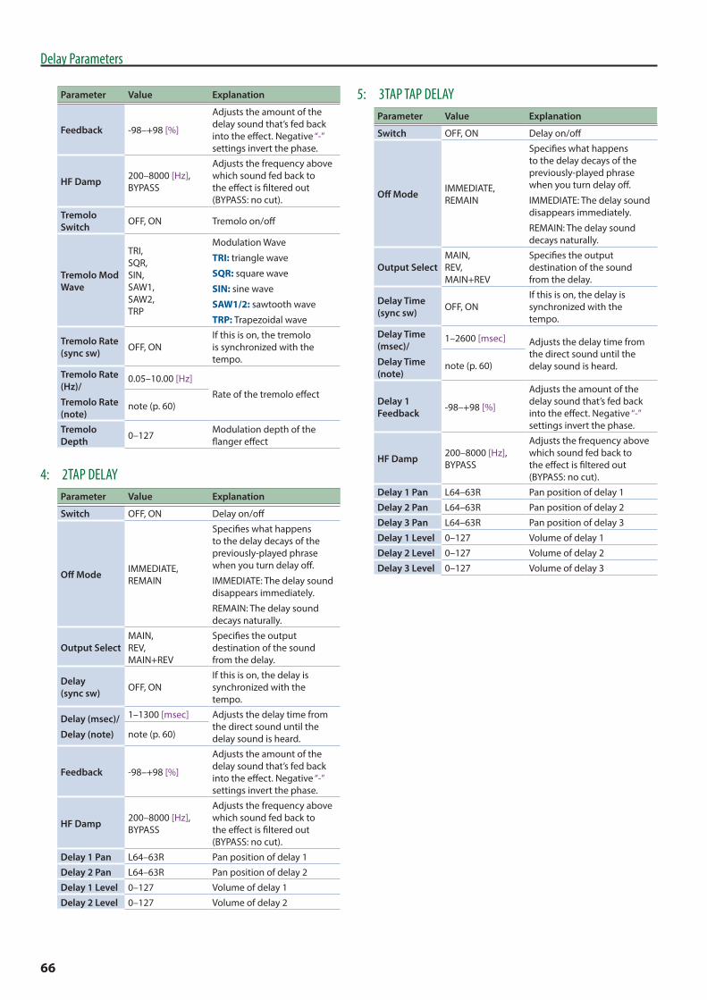
66
Delay Parameters
Parameter Value Explanation
Feedback -98–+98 [%]
Adjusts the amount of the delay sound that’s fed back into the effect. Negative “-” settings invert the phase.
HF Damp 200–8000 [Hz], BYPASS
Adjusts the frequency above which sound fed back to the effect is filtered out (BYPASS: no cut).
Tremolo Switch OFF, ON Tremolo on/off
Tremolo Mod Wave
TRI, SQR, SIN, SAW1, SAW2, TRP
Modulation Wave
TRI: triangle wave
SQR: square wave
SIN: sine wave
SAW1/2: sawtooth wave
TRP: Trapezoidal wave
Tremolo Rate (sync sw) OFF, ON
If this is on, the tremolo is synchronized with the tempo.
Tremolo Rate (Hz)/
Tremolo Rate (note)
0.05–10.00 [Hz]
Rate of the tremolo effectnote (p. 60)
Tremolo Depth 0–127 Modulation depth of the
flanger effect
4: 2TAP DELAYParameter Value Explanation
Switch OFF, ON Delay on/off
Off Mode IMMEDIATE, REMAIN
Specifies what happens to the delay decays of the previously-played phrase when you turn delay off.
IMMEDIATE: The delay sound disappears immediately.
REMAIN: The delay sound decays naturally.
Output SelectMAIN, REV, MAIN+REV
Specifies the output destination of the sound from the delay.
Delay (sync sw) OFF, ON
If this is on, the delay is synchronized with the tempo.
Delay (msec)/
Delay (note)
1–1300 [msec] Adjusts the delay time from the direct sound until the delay sound is heard.note (p. 60)
Feedback -98–+98 [%]
Adjusts the amount of the delay sound that’s fed back into the effect. Negative “-” settings invert the phase.
HF Damp 200–8000 [Hz], BYPASS
Adjusts the frequency above which sound fed back to the effect is filtered out (BYPASS: no cut).
Delay 1 Pan L64–63R Pan position of delay 1
Delay 2 Pan L64–63R Pan position of delay 2
Delay 1 Level 0–127 Volume of delay 1
Delay 2 Level 0–127 Volume of delay 2
5: 3TAP TAP DELAYParameter Value Explanation
Switch OFF, ON Delay on/off
Off Mode IMMEDIATE, REMAIN
Specifies what happens to the delay decays of the previously-played phrase when you turn delay off.
IMMEDIATE: The delay sound disappears immediately.
REMAIN: The delay sound decays naturally.
Output SelectMAIN, REV, MAIN+REV
Specifies the output destination of the sound from the delay.
Delay Time (sync sw) OFF, ON
If this is on, the delay is synchronized with the tempo.
Delay Time (msec)/
Delay Time (note)
1–2600 [msec] Adjusts the delay time from the direct sound until the delay sound is heard.note (p. 60)
Delay 1 Feedback -98–+98 [%]
Adjusts the amount of the delay sound that’s fed back into the effect. Negative “-” settings invert the phase.
HF Damp 200–8000 [Hz], BYPASS
Adjusts the frequency above which sound fed back to the effect is filtered out (BYPASS: no cut).
Delay 1 Pan L64–63R Pan position of delay 1
Delay 2 Pan L64–63R Pan position of delay 2
Delay 3 Pan L64–63R Pan position of delay 3
Delay 1 Level 0–127 Volume of delay 1
Delay 2 Level 0–127 Volume of delay 2
Delay 3 Level 0–127 Volume of delay 3
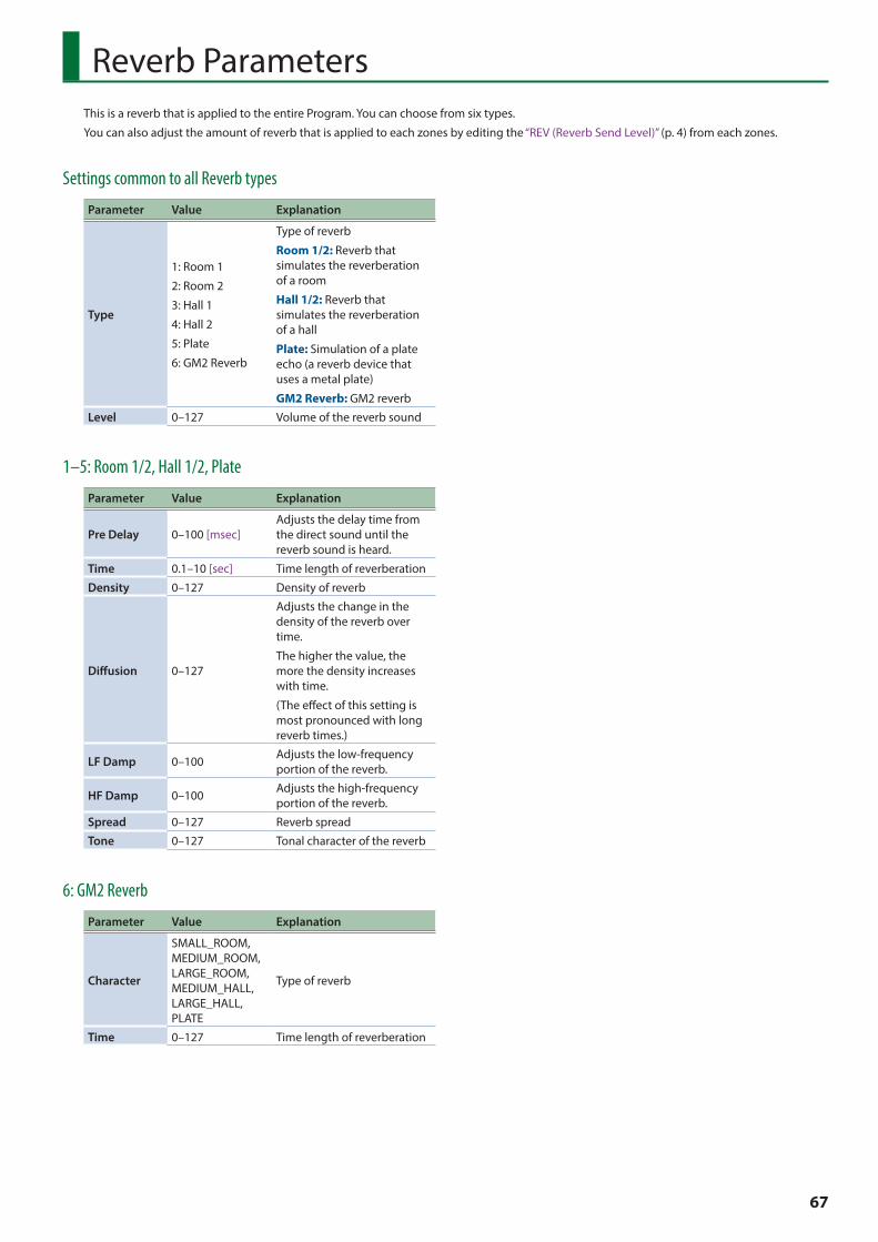
67
This is a reverb that is applied to the entire Program. You can choose from six types.
You can also adjust the amount of reverb that is applied to each zones by editing the “REV (Reverb Send Level)” (p. 4) from each zones.
Reverb Parameters
Settings common to all Reverb types
Parameter Value Explanation
Type
1: Room 1
2: Room 2
3: Hall 1
4: Hall 2
5: Plate
6: GM2 Reverb
Type of reverb
Room 1/2: Reverb that simulates the reverberation of a room
Hall 1/2: Reverb that simulates the reverberation of a hall
Plate: Simulation of a plate echo (a reverb device that uses a metal plate)
GM2 Reverb: GM2 reverb
Level 0–127 Volume of the reverb sound
1–5: Room 1/2, Hall 1/2, Plate
Parameter Value Explanation
Pre Delay 0–100 [msec]Adjusts the delay time from the direct sound until the reverb sound is heard.
Time 0.1–10 [sec] Time length of reverberation
Density 0–127 Density of reverb
Diffusion 0–127
Adjusts the change in the density of the reverb over time.
The higher the value, the more the density increases with time.
(The effect of this setting is most pronounced with long reverb times.)
LF Damp 0–100 Adjusts the low-frequency portion of the reverb.
HF Damp 0–100 Adjusts the high-frequency portion of the reverb.
Spread 0–127 Reverb spread
Tone 0–127 Tonal character of the reverb
6: GM2 Reverb
Parameter Value Explanation
Character
SMALL_ROOM, MEDIUM_ROOM, LARGE_ROOM, MEDIUM_HALL, LARGE_HALL, PLATE
Type of reverb
Time 0–127 Time length of reverberation

68
EQ Parameters
Parameter Value Explanation
Low Gain -12–+12 [dB] Gain of the low range
Low Freq 16–16000 [Hz] Frequency of the low range
Mid1 Gain -12–+12 [dB] Gain of the middle range 1
Mid1 Freq 16–16000 [Hz] Frequency of the middle range 1
Mid1 Q 0.5, 1.0, 2.0, 4.0, 8.0
Width of the middle range 1
Set a higher value for Q to narrow the range to be affected.
Mid2 Gain -12–+12 [dB] Gain of the middle range 2
Mid2 Freq 16–16000 [Hz] Frequency of the middle range 2
Mid2 Q 0.5, 1.0, 2.0, 4.0, 8.0
Width of the middle range 2
Set a higher value for Q to narrow the range to be affected.
Mid3 Gain -12–+12 [dB] Gain of the middle range 3
Mid3 Freq 16–16000 [Hz] Frequency of the middle range 3
Mid3 Q 0.5, 1.0, 2.0, 4.0, 8.0
Width of the middle range 3
Set a higher value for Q to narrow the range to be affected.
High Gain -12–+12 [dB] Gain of the high range
High Freq 16–16000 [Hz] Frequency of the high range
Input Gain -15–+15 [dB] Gain of the Input
This is a five-band equalizer that is applied to the entire Program.
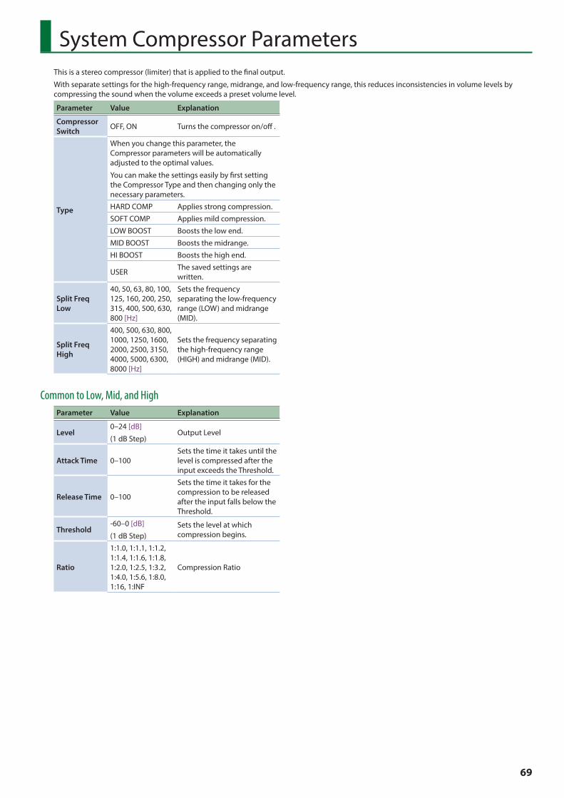
69
System Compressor Parameters
Parameter Value Explanation
Compressor Switch OFF, ON Turns the compressor on/off .
Type
When you change this parameter, the Compressor parameters will be automatically adjusted to the optimal values.
You can make the settings easily by first setting the Compressor Type and then changing only the necessary parameters.
HARD COMP Applies strong compression.
SOFT COMP Applies mild compression.
LOW BOOST Boosts the low end.
MID BOOST Boosts the midrange.
HI BOOST Boosts the high end.
USER The saved settings are written.
Split Freq Low
40, 50, 63, 80, 100, 125, 160, 200, 250, 315, 400, 500, 630, 800 [Hz]
Sets the frequency separating the low-frequency range (LOW) and midrange (MID).
Split Freq High
400, 500, 630, 800, 1000, 1250, 1600, 2000, 2500, 3150, 4000, 5000, 6300, 8000 [Hz]
Sets the frequency separating the high-frequency range (HIGH) and midrange (MID).
Common to Low, Mid, and HighParameter Value Explanation
Level0–24 [dB]
(1 dB Step)Output Level
Attack Time 0–100Sets the time it takes until the level is compressed after the input exceeds the Threshold.
Release Time 0–100
Sets the time it takes for the compression to be released after the input falls below the Threshold.
Threshold-60–0 [dB]
(1 dB Step)Sets the level at which compression begins.
Ratio
1:1.0, 1:1.1, 1:1.2, 1:1.4, 1:1.6, 1:1.8, 1:2.0, 1:2.5, 1:3.2, 1:4.0, 1:5.6, 1:8.0, 1:16, 1:INF
Compression Ratio
This is a stereo compressor (limiter) that is applied to the final output.
With separate settings for the high-frequency range, midrange, and low-frequency range, this reduces inconsistencies in volume levels by compressing the sound when the volume exceeds a preset volume level.
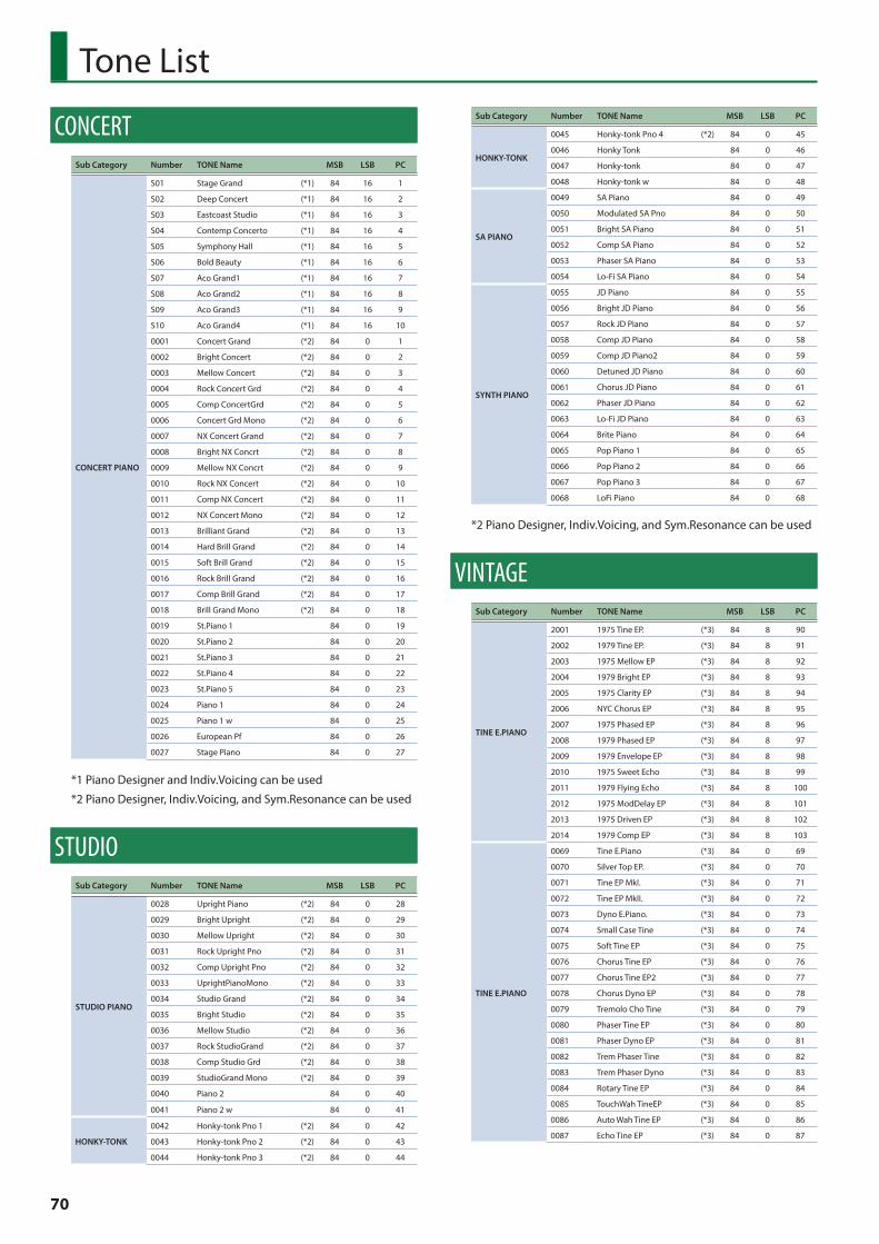
70
Tone List
CONCERTSub Category Number TONE Name MSB LSB PC
CONCERT PIANO
S01 Stage Grand (*1) 84 16 1
S02 Deep Concert (*1) 84 16 2
S03 Eastcoast Studio (*1) 84 16 3
S04 Contemp Concerto (*1) 84 16 4
S05 Symphony Hall (*1) 84 16 5
S06 Bold Beauty (*1) 84 16 6
S07 Aco Grand1 (*1) 84 16 7
S08 Aco Grand2 (*1) 84 16 8
S09 Aco Grand3 (*1) 84 16 9
S10 Aco Grand4 (*1) 84 16 10
0001 Concert Grand (*2) 84 0 1
0002 Bright Concert (*2) 84 0 2
0003 Mellow Concert (*2) 84 0 3
0004 Rock Concert Grd (*2) 84 0 4
0005 Comp ConcertGrd (*2) 84 0 5
0006 Concert Grd Mono (*2) 84 0 6
0007 NX Concert Grand (*2) 84 0 7
0008 Bright NX Concrt (*2) 84 0 8
0009 Mellow NX Concrt (*2) 84 0 9
0010 Rock NX Concert (*2) 84 0 10
0011 Comp NX Concert (*2) 84 0 11
0012 NX Concert Mono (*2) 84 0 12
0013 Brilliant Grand (*2) 84 0 13
0014 Hard Brill Grand (*2) 84 0 14
0015 Soft Brill Grand (*2) 84 0 15
0016 Rock Brill Grand (*2) 84 0 16
0017 Comp Brill Grand (*2) 84 0 17
0018 Brill Grand Mono (*2) 84 0 18
0019 St.Piano 1 84 0 19
0020 St.Piano 2 84 0 20
0021 St.Piano 3 84 0 21
0022 St.Piano 4 84 0 22
0023 St.Piano 5 84 0 23
0024 Piano 1 84 0 24
0025 Piano 1 w 84 0 25
0026 European Pf 84 0 26
0027 Stage Piano 84 0 27
*1 Piano Designer and Indiv.Voicing can be used
*2 Piano Designer, Indiv.Voicing, and Sym.Resonance can be used
STUDIOSub Category Number TONE Name MSB LSB PC
STUDIO PIANO
0028 Upright Piano (*2) 84 0 28
0029 Bright Upright (*2) 84 0 29
0030 Mellow Upright (*2) 84 0 30
0031 Rock Upright Pno (*2) 84 0 31
0032 Comp Upright Pno (*2) 84 0 32
0033 UprightPianoMono (*2) 84 0 33
0034 Studio Grand (*2) 84 0 34
0035 Bright Studio (*2) 84 0 35
0036 Mellow Studio (*2) 84 0 36
0037 Rock StudioGrand (*2) 84 0 37
0038 Comp Studio Grd (*2) 84 0 38
0039 StudioGrand Mono (*2) 84 0 39
0040 Piano 2 84 0 40
0041 Piano 2 w 84 0 41
HONKY-TONK
0042 Honky-tonk Pno 1 (*2) 84 0 42
0043 Honky-tonk Pno 2 (*2) 84 0 43
0044 Honky-tonk Pno 3 (*2) 84 0 44
Sub Category Number TONE Name MSB LSB PC
HONKY-TONK
0045 Honky-tonk Pno 4 (*2) 84 0 45
0046 Honky Tonk 84 0 46
0047 Honky-tonk 84 0 47
0048 Honky-tonk w 84 0 48
SA PIANO
0049 SA Piano 84 0 49
0050 Modulated SA Pno 84 0 50
0051 Bright SA Piano 84 0 51
0052 Comp SA Piano 84 0 52
0053 Phaser SA Piano 84 0 53
0054 Lo-Fi SA Piano 84 0 54
SYNTH PIANO
0055 JD Piano 84 0 55
0056 Bright JD Piano 84 0 56
0057 Rock JD Piano 84 0 57
0058 Comp JD Piano 84 0 58
0059 Comp JD Piano2 84 0 59
0060 Detuned JD Piano 84 0 60
0061 Chorus JD Piano 84 0 61
0062 Phaser JD Piano 84 0 62
0063 Lo-Fi JD Piano 84 0 63
0064 Brite Piano 84 0 64
0065 Pop Piano 1 84 0 65
0066 Pop Piano 2 84 0 66
0067 Pop Piano 3 84 0 67
0068 LoFi Piano 84 0 68
*2 Piano Designer, Indiv.Voicing, and Sym.Resonance can be used
VINTAGESub Category Number TONE Name MSB LSB PC
TINE E.PIANO
2001 1975 Tine EP. (*3) 84 8 90
2002 1979 Tine EP. (*3) 84 8 91
2003 1975 Mellow EP (*3) 84 8 92
2004 1979 Bright EP (*3) 84 8 93
2005 1975 Clarity EP (*3) 84 8 94
2006 NYC Chorus EP (*3) 84 8 95
2007 1975 Phased EP (*3) 84 8 96
2008 1979 Phased EP (*3) 84 8 97
2009 1979 Envelope EP (*3) 84 8 98
2010 1975 Sweet Echo (*3) 84 8 99
2011 1979 Flying Echo (*3) 84 8 100
2012 1975 ModDelay EP (*3) 84 8 101
2013 1975 Driven EP (*3) 84 8 102
2014 1979 Comp EP (*3) 84 8 103
TINE E.PIANO
0069 Tine E.Piano (*3) 84 0 69
0070 Silver Top EP. (*3) 84 0 70
0071 Tine EP MkI. (*3) 84 0 71
0072 Tine EP MkII. (*3) 84 0 72
0073 Dyno E.Piano. (*3) 84 0 73
0074 Small Case Tine (*3) 84 0 74
0075 Soft Tine EP (*3) 84 0 75
0076 Chorus Tine EP (*3) 84 0 76
0077 Chorus Tine EP2 (*3) 84 0 77
0078 Chorus Dyno EP (*3) 84 0 78
0079 Tremolo Cho Tine (*3) 84 0 79
0080 Phaser Tine EP (*3) 84 0 80
0081 Phaser Dyno EP (*3) 84 0 81
0082 Trem Phaser Tine (*3) 84 0 82
0083 Trem Phaser Dyno (*3) 84 0 83
0084 Rotary Tine EP (*3) 84 0 84
0085 TouchWah TineEP (*3) 84 0 85
0086 Auto Wah Tine EP (*3) 84 0 86
0087 Echo Tine EP (*3) 84 0 87
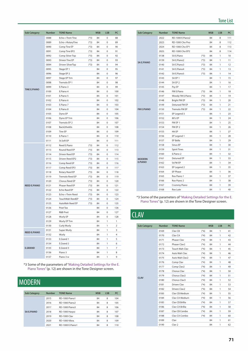
71
Tone List
Sub Category Number TONE Name MSB LSB PC
TINE E.PIANO
0088 Echo->Trem Tine (*3) 84 0 88
0089 Echo->RotaryTine (*3) 84 0 89
0090 Comp Tine EP (*3) 84 0 90
0091 Comp Tine EP2 (*3) 84 0 91
0092 Comp Silver Top (*3) 84 0 92
0093 Driven Tine EP (*3) 84 0 93
0094 Driven SilverTop (*3) 84 0 94
0095 Stage EP 1 84 0 95
0096 Stage EP 2 84 0 96
0097 Stage EP Trm 84 0 97
0098 Tremolo EP 1 84 0 98
0099 E.Piano 3 84 0 99
0100 E.Piano 4 84 0 100
0101 E.Piano 5 84 0 101
0102 E.Piano 6 84 0 102
0103 E.Piano 7 84 0 103
0104 E.Piano 8 84 0 104
0105 Dyno EP 84 0 105
0106 Dyno EP Trm 84 0 106
0107 Tremolo EP 2 84 0 107
0108 Back2the60s 84 0 108
0109 Tine EP 84 0 109
0110 E.Piano 1 84 0 110
0111 St.Soft EP 84 0 111
REED E.PIANO
0112 Reed E.Piano (*3) 84 0 112
0113 Round Reed EP (*3) 84 0 113
0114 Driven Reed EP (*3) 84 0 114
0115 Driven Reed EP2 (*3) 84 0 115
0116 Comp Reed EP (*3) 84 0 116
0117 Comp Reed EP2 (*3) 84 0 117
0118 Rotary Reed EP (*3) 84 0 118
0119 Tremolo Reed EP (*3) 84 0 119
0120 Chorus Reed EP (*3) 84 0 120
0121 Phaser Reed EP (*3) 84 0 121
0122 Echo Reed EP (*3) 84 0 122
0123 Echo->Trem Reed (*3) 84 0 123
0124 TouchWah ReedEP (*3) 84 0 124
0125 AutoWah Reed EP (*3) 84 0 125
0126 Pnet Tee 84 0 126
0127 R&B Pnet 84 0 127
0128 Wurly EP 84 0 128
0129 Wurly EP Trm 84 1 1
0130 Curly Wurly 84 1 2
REED E.PIANO0131 Super Wurly 84 1 3
0132 Wurly 84 1 4
E.GRAND
0133 E.Grand 1 84 1 5
0134 E.Grand 2 84 1 6
0135 E.Grand 3 84 1 7
0136 Piano 3 84 1 8
0137 Piano 3 w 84 1 9
*3 Some of the parameters of “Making Detailed Settings for the E. Piano Tones” (p. 12) are shown in the Tone Designer screen.
MODERNSub Category Number TONE Name MSB LSB PC
SA E.PIANO
2015 RD-1000 Piano1 84 8 104
2016 RD-1000 Piano2 84 8 105
2017 RD-1000 Piano3 84 8 106
2018 RD-1000 Harpsi 84 8 107
2019 RD-1000 Clav 84 8 108
2020 RD-1000 Vibra. 84 8 109
2021 RD-1000 E.Piano1 84 8 110
Sub Category Number TONE Name MSB LSB PC
SA E.PIANO
2022 RD-1000 E.Piano2 84 8 111
2023 RD-1000 Cho Pno 84 8 112
2024 RD-1000 Cho EP1 84 8 113
2025 RD-1000 Cho EP2 84 8 114
0138 SA E.Piano (*3) 84 1 10
0139 SA E.Piano2 (*3) 84 1 11
0140 SA E.Piano3 (*3) 84 1 12
0141 SA E.Piano4 (*3) 84 1 13
0142 SA E.Piano5 (*3) 84 1 14
0143 SA EP 1 84 1 15
0144 SA EP 2 84 1 16
0145 Psy EP 84 1 17
FM E.PIANO
0146 FM E.Piano (*3) 84 1 18
0147 Woody FM E.Piano (*3) 84 1 19
0148 Bright FM EP (*3) 84 1 20
0149 Detuned FM EP (*3) 84 1 21
0150 Tremolo FM EP (*3) 84 1 22
0151 EP Legend 3 84 1 23
0152 80's EP 84 1 24
0153 FM EP 1 84 1 25
0154 FM EP 2 84 1 26
MODERN E.PIANO
0155 Hit EP 84 1 27
0156 EP Legend 1 84 1 28
0157 EP Belle 84 1 29
0158 Sinus EP 84 1 30
0159 Spirit Tines 84 1 31
0160 E.Piano 2 84 1 32
0161 Detuned EP 84 1 33
0162 St.FM EP 84 1 34
0163 EP Legend 2 84 1 35
0164 EP Phase 84 1 36
0165 Rox Piano 1 84 1 37
0166 Rox Piano 2 84 1 38
0167 Crummy Piano 84 1 39
0168 Rox Lute 84 1 40
*3 Some of the parameters of “Making Detailed Settings for the E. Piano Tones” (p. 12) are shown in the Tone Designer screen.
CLAVSub Category Number TONE Name MSB LSB PC
CLAV
0169 Clav CB (*4) 84 1 41
0170 Clav CA (*4) 84 1 42
0171 Phaser Clav (*4) 84 1 43
0172 Phaser Clav2 (*4) 84 1 44
0173 Touch Wah Clav (*4) 84 1 45
0174 Auto Wah Clav (*4) 84 1 46
0175 Auto Wah Clav2 (*4) 84 1 47
0176 Comp Clav (*4) 84 1 48
0177 Comp Clav2 (*4) 84 1 49
0178 Chorus Clav (*4) 84 1 50
0179 Chorus Clav2 (*4) 84 1 51
0180 Chorus Clav3 (*4) 84 1 52
0181 Driven Clav (*4) 84 1 53
0182 Driven Clav2 (*4) 84 1 54
0183 Clav CB Medium (*4) 84 1 55
0184 Clav CA Medium (*4) 84 1 56
0185 Clav CB Brillia (*4) 84 1 57
0186 Clav CA Brillia (*4) 84 1 58
0187 Clav CB Combo (*4) 84 1 59
0188 Clav CA Combo (*4) 84 1 60
0189 Clav 84 1 61
0190 Clav 2 84 1 62
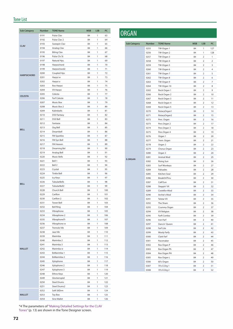
72
Tone List
Sub Category Number TONE Name MSB LSB PC
CLAV
0191 Pulse Clav 84 1 63
0192 Pulse Clav 2 84 1 64
0193 Sweepin Clav 84 1 65
0194 Analog Clav 84 1 66
0195 Biting Clav 84 1 67
0196 Pulse Clv St 84 1 68
HARPSICHORD
0197 Natural Hps. 84 1 69
0198 Harpsichord 84 1 70
0199 Harpsichord2 84 1 71
0200 Coupled Hps 84 1 72
0201 Harpsi w 84 1 73
0202 Harpsi o 84 1 74
0203 Rox Harpsi 84 1 75
0204 VX Harpsi 84 1 76
CELESTA0205 Celesta 84 1 77
0206 Farf Celeste 84 1 78
BELL
0207 Music Box 84 1 79
0208 Music Box 2 84 1 80
0209 Kalimbells 84 1 81
0210 D50 Fantasy 84 1 82
0211 D50 Bell 84 1 83
0212 Fantasia 84 1 84
0213 Org Bell 84 1 85
0214 Dreambell 84 1 86
0215 FM Sparkles 84 1 87
0216 FM Syn Bell 84 1 88
0217 FM Heaven 84 1 89
0218 Dreaming Bel 84 1 90
0219 Analog Bell 84 1 91
0220 Music Bells 84 1 92
BELL
0221 Bell 1 84 1 93
0222 Bell 2 84 1 94
0223 Crystal 84 1 95
0224 Tinkle Bell 84 1 96
0225 Icy Keys 84 1 97
0226 TubularBells 84 1 98
0227 TubularBell2 84 1 99
0228 Church Bell 84 1 100
0229 Carillon 84 1 101
0230 Carillon 2 84 1 102
0231 Tower Bell 84 1 103
0232 Bell Ring 84 1 104
MALLET
0233 Vibraphone 84 1 105
0234 Vibraphone 2 84 1 106
0235 VibraphoneTr 84 1 107
0236 Vibraphone w 84 1 108
0237 Tremolo Vib 84 1 109
0238 Jazz Vib 84 1 110
0239 Marimba 84 1 111
0240 Marimba 2 84 1 112
0241 Marimba 3 84 1 113
0242 Marimba w 84 1 114
0243 BsMarimba 1 84 1 115
0244 BsMarimba 2 84 1 116
0245 Xylophone 84 1 117
0246 Xylophone 2 84 1 118
0247 Xylophone 3 84 1 119
0248 Ethno Keys 84 1 120
0249 Glockenspiel 84 1 121
0250 Steel Drums 84 1 122
0251 Steel Drums2 84 1 123
MALLET
0252 Soft StlDrm 84 1 124
0253 Toy Box 84 1 125
0254 Sine Mallet 84 1 126
*4 The parameters of “Making Detailed Settings for the CLAV Tones” (p. 13) are shown in the Tone Designer screen.
ORGANSub Category Number TONE Name MSB LSB PC
E.ORGAN
0255 TW-Organ 1 84 1 127
0256 TW-Organ 2 84 1 128
0257 TW-Organ 3 84 2 1
0258 TW-Organ 4 84 2 2
0259 TW-Organ 5 84 2 3
0260 TW-Organ 6 84 2 4
0261 TW-Organ 7 84 2 5
0262 TW-Organ 8 84 2 6
0263 TW-Organ 9 84 2 7
0264 TW-Organ 10 84 2 8
0265 Rock Organ 1 84 2 9
0266 Rock Organ 2 84 2 10
0267 Rock Organ 3 84 2 11
0268 Rock Organ 4 84 2 12
0269 Rock Organ 5 84 2 13
0270 RotaryOrgan1 84 2 14
0271 RotaryOrgan2 84 2 15
0272 Perc. Organ 84 2 16
0273 Perc.Organ 2 84 2 17
0274 Perc.Organ 3 84 2 18
0275 Perc.Organ 4 84 2 19
0276 Organ 1 84 2 20
0277 Trem. Organ 84 2 21
0278 Organ 2 84 2 22
0279 Chorus Organ 84 2 23
0280 Organ 3 84 2 24
0281 Animal Mod 84 2 25
0282 Rising Sun 84 2 26
0283 Surf Monkeys 84 2 27
0284 Palisades 84 2 28
0285 Kitchen Soul 84 2 29
0286 BreakOnThru 84 2 30
0287 Calif.Sun 84 2 31
0288 Steppin' VX 84 2 32
0289 Costello+Mod 84 2 33
0290 Archie's Mod 84 2 34
0291 Telstar VX 84 2 35
0292 The Sham 84 2 36
0293 Crummy Organ 84 2 37
0294 VX Religion 84 2 38
0295 Farfi Combo 84 2 39
0296 Iron Farf 84 2 40
0297 Dancin' Queen 84 2 41
0298 Farf Lite 84 2 42
0299 Wooly Farfy 84 2 43
0300 Clark Farf 84 2 44
0301 Pacemaker 84 2 45
0302 Rox Organ P 84 2 46
0303 Rox Organ Ph 84 2 47
0304 Rox Organ PH 84 2 48
0305 Rox Organ L 84 2 49
0306 60's Organ 84 2 50
0307 70's E.Org 1 84 2 51
0308 70's E.Org 2 84 2 52

73
Tone List
Sub Category Number TONE Name MSB LSB PC
E.ORGAN
0309 70's E.Organ 84 2 53
0310 E.Organ 1 84 2 54
0311 E.Organ 2 84 2 55
0312 E.Organ 3 84 2 56
0313 E.Organ 4 84 2 57
0314 E.Organ 5 84 2 58
0315 E.Organ 6 84 2 59
0316 E.Organ 7 84 2 60
0317 Theater Org 84 2 61
0318 Ana Organ 1 84 2 62
0319 Ana Organ 2 84 2 63
0320 Ana Organ 3 84 2 64
0321 Ana Organ 4 84 2 65
0322 Ana Organ 5 84 2 66
PIPE ORGAN
0323 Puff Organ 84 2 67
0324 Nason Flute 84 2 68
0325 Massive Pipe 84 2 69
PIPE ORGAN
0326 Mid Pipe Org 84 2 70
0327 Grand Pipes 84 2 71
0328 Church Org 1 84 2 72
0329 Church Org 2 84 2 73
0330 Church Org 3 84 2 74
0331 Reed Organ 84 2 75
ACCORDION
0332 Accordion Fr 84 2 76
0333 Accordion It 84 2 77
0334 AccordionIt2 84 2 78
0335 Musette 84 2 79
0336 Vodkakordion 84 2 80
0337 Bandoneon 84 2 81
HARMONICA0338 Harmonica 84 2 82
0339 Harmonica 2 84 2 83
STRINGSSub Category Number TONE Name MSB LSB PC
ENSEMBLE STRINGS
0340 Slow FullStrings 84 2 84
0341 Full Strings 84 2 85
0342 GX Strings 84 2 86
0343 Mood Strings 84 2 87
0344 Slow Strings 84 2 88
0345 DecayStrings 84 2 89
0346 Strings 84 2 90
0347 Strings 2 84 2 91
0348 Strings 3 84 2 92
0349 Strings 4 84 2 93
0350 Strings 5 84 2 94
0351 Strings 6 84 2 95
0352 Stage Str 1 84 2 96
0353 Stage Str 2 84 2 97
0354 Pop Str 84 2 98
0355 Hall Strings 84 2 99
0356 Marc.Str 84 2 100
0357 StringsStacc 84 2 101
0358 Oct Strings 84 2 102
0359 Tremolo Str 84 2 103
0360 Tron Strings 84 2 104
0361 Tron Strings2 84 2 105
0362 Symphonic Tron 84 2 106
0363 Moody Tron 84 2 107
0364 TapeStrings1 84 2 108
0365 TapeStrings2 84 2 109
ENSEMBLE STRINGS
0366 Hybrid Str 84 2 110
0367 PizzicatoStr 84 2 111
0368 Pizz 1 84 2 112
0369 Pizz 2 84 2 113
Sub Category Number TONE Name MSB LSB PC
SOLO STRINGS
0370 Violin 84 2 114
0371 Violin 2 84 2 115
0372 Slow Violin 84 2 116
0373 Bright Vln 84 2 117
0374 Viola 84 2 118
0375 Cello 84 2 119
SOLO STRINGS
0376 Bright Vc 84 2 120
0377 Contrabass 84 2 121
0378 Fiddle 84 2 122
0379 Tron Violins 84 2 123
0380 Tron Cello 84 2 124
ORCHESTRAL
0381 Orchestra 84 2 125
0382 Orc.Unison 1 84 2 126
0383 Orc.Unison 2 84 2 127
0384 Full Orc 84 2 128
PAD/CHOIRSub Category Number TONE Name MSB LSB PC
SYNTH PAD/STR
0385 Wide Soft Pad 84 3 1
0386 Silky Way 84 3 2
0387 CalmChoirPad 84 3 3
0388 Decay Choir Pad 84 3 4
0389 Soft Pad 1 84 3 5
0390 Soft Pad 2 84 3 6
0391 Soft Pad 3 84 3 7
0392 Soft Pad 4 84 3 8
0393 Soft Pad 5 84 3 9
0394 Soft Pad 6 84 3 10
0395 Soft Pad 7 84 3 11
0396 Soft Pad 8 84 3 12
0397 Soft Pad 9 84 3 13
0398 Soft Pad 10 84 3 14
0399 Dreamheaven 84 3 15
0400 Oct Heaven 84 3 16
0401 VintageStr 1 84 3 17
0402 VintageStr 2 84 3 18
0403 VintageStr 3 84 3 19
0404 VintageStr 4 84 3 20
0405 VintageStr 5 84 3 21
0406 VintageStr 6 84 3 22
0407 VintageStr 7 84 3 23
0408 JX Strings 84 3 24
0409 JP Strings 1 84 3 25
0410 JP Strings 2 84 3 26
0411 106 Strings 84 3 27
0412 Sol Strings 84 3 28
0413 Rhapsody STR 84 3 29
0414 PWM Str 1 84 3 30
0415 PWM Str 2 84 3 31
0416 PWM Str 3 84 3 32
0417 Fading Str 84 3 33
0418 ParadisePad 84 3 34
0419 80s Strings 84 3 35
0420 Stringship 84 3 36
0421 Airy Pad 84 3 37
0422 Neo RS-202 84 3 38

74
Tone List
Sub Category Number TONE Name MSB LSB PC
SYNTH PAD/STR
0423 Sawtooth Str 84 3 39
0424 Syn.Strings1 84 3 40
0425 Syn.Strings2 84 3 41
0426 Syn.Strings3 84 3 42
0427 Pulse Pad 84 3 43
0428 Hollow Pad 1 84 3 44
0429 WarmHeaven 1 84 3 45
0430 WarmHeaven 2 84 3 46
0431 Heaven Pad 1 84 3 47
0432 Heaven Pad 2 84 3 48
0433 Heaven Pad 3 84 3 49
0434 Heaven Pad 4 84 3 50
0435 FineWinePad1 84 3 51
0436 FineWinePad2 84 3 52
0437 5th Pad 1 84 3 53
0438 5th Pad 2 84 3 54
0439 Nu Epic Pad 84 3 55
0440 Angelis Pad 84 3 56
0441 TrnsSweepPad 84 3 57
0442 Giant Sweep 84 3 58
0443 Voyager 84 3 59
0444 Digital Pad 84 3 60
0445 NuSoundtrack 84 3 61
0446 Xadecimal 84 3 62
0447 Strobe Pad 84 3 63
0448 BUBBLE 2 84 3 64
0449 BUBBLE 3 84 3 65
0450 Soft PWM Pad 84 3 66
0451 Org Pad 84 3 67
0452 Hollow Pad 2 84 3 68
0453 SavannaPad 1 84 3 69
0454 SavannaPad 2 84 3 70
0455 SavannaPad 3 84 3 71
0456 PWM Pad 2 84 3 72
0457 Str Machine 84 3 73
0458 Reso Pad 84 3 74
0459 BPF Pad 84 3 75
0460 Sweep Pad 84 3 76
0461 Sweep Pad 2 84 3 77
0462 Sweep Pad 3 84 3 78
0463 Sweep Pad 4 84 3 79
0464 Scoop Pad 1 84 3 80
0465 Scoop Pad 2 84 3 81
0466 Brite Wine 84 3 82
0467 Wine Pad 84 3 83
0468 Warm Pad 84 3 84
0469 Sine Pad 84 3 85
0470 Bowed Glass 84 3 86
0471 Metal Pad 84 3 87
0472 Halo Pad 84 3 88
0473 Soundtrack 84 3 89
0474 Star Theme 84 3 90
SYNTH BELLPAD
0475 Air Key 1 84 3 91
0476 Air Key 2 84 3 92
0477 Sweet Keys 84 3 93
0478 Soft Bell 84 3 94
0479 Stacc Heaven 84 3 95
0480 DigitalDream 84 3 96
0481 Analog Dream 84 3 97
0482 Harp Pad 84 3 98
0483 Ice Rain 84 3 99
SYNTH BELLPAD
0484 Atmosphere 84 3 100
0485 Brightness 84 3 101
0486 Dreaming Box 84 3 102
Sub Category Number TONE Name MSB LSB PC
VOX CHOIR
0487 Large Choir 84 3 103
0488 GX Choir 84 3 104
0489 Choir Aahs 84 3 105
0490 Chorus Aahs 84 3 106
0491 Choir Pad 84 3 107
0492 Angels Choir 84 3 108
0493 Aerial Choir 84 3 109
0494 Voice Oohs 84 3 110
0495 Doo Pad 84 3 111
0496 Humming 84 3 112
0497 Humming 2 84 3 113
0498 Humming 3 84 3 114
0499 Gospel Hum 84 3 115
0500 Decay Choir 84 3 116
0501 Vox Pad 1 84 3 117
0502 Vox Pad 2 84 3 118
0503 Dreamvox 1 84 3 119
0504 Dreamvox 2 84 3 120
0505 80s Vox 84 3 121
0506 SynVox 84 3 122
0507 SynVox 2 84 3 123
0508 SynVox 3 84 3 124
0509 Mini Vox 84 3 125
0510 Chipmunk 84 3 126
0511 Sample Opera 84 3 127
0512 Sad Ceremony 84 3 128
0513 5th Voice 84 4 1
0514 Sop Vox 84 4 2
0515 Analog Voice 84 4 3
0516 Space Voice 84 4 4
0517 Itopia 84 4 5
0518 Tron Choir 84 4 6
0519 Tron Vox 84 4 7
SCAT0520 Jazz Scat 1 84 4 8
0521 Jazz Scat 2 84 4 9
BASSSub Category Number TONE Name MSB LSB PC
AC.BASS
0522 Acoustic Bs 84 4 10
0523 Acoustic Bs2 84 4 11
0524 Acoustic Bs3 84 4 12
0525 String Slap 84 4 13
E.BASS
0526 Fingered Bs 84 4 14
0527 Fingered Bs2 84 4 15
0528 Fingered Bs3 84 4 16
0529 Fingered Bs4 84 4 17
E.BASS
0530 Pick Bass 84 4 18
0531 Picked Bass 84 4 19
0532 Fretless Bs 84 4 20
0533 FretlessBs 2 84 4 21
0534 FretlessBs 3 84 4 22
0535 Finger Slap 84 4 23
0536 Finger Slap2 84 4 24
0537 Slap Bass 1 84 4 25
0538 Slap Bass 2 84 4 26
0539 Return2Base! 84 4 27

75
Tone List
Sub Category Number TONE Name MSB LSB PC
SYNTH BASS
0540 MG Bass 1 84 4 28
0541 MG Bass 2 84 4 29
0542 MG Bass 3 84 4 30
0543 Modular Bs 1 84 4 31
0544 Modular Bs 2 84 4 32
0545 PWM Bass 1 84 4 33
0546 PWM Bass 2 84 4 34
0547 Big Mini 84 4 35
0548 Fat Analog 84 4 36
0549 Spike Bass 84 4 37
0550 SH Bass 84 4 38
0551 Intrusive Bs 84 4 39
0552 Synth Bass 1 84 4 40
0553 Synth Bass 2 84 4 41
0554 Synth Bass 3 84 4 42
0555 Synth Bass 4 84 4 43
0556 Synth Bass 5 84 4 44
0557 Synth Bass 6 84 4 45
0558 Synth Bass 7 84 4 46
0559 Synth Bass 8 84 4 47
0560 Synth Bass 9 84 4 48
0561 Synth Bass10 84 4 49
0562 Synth Bass11 84 4 50
0563 Synth Bass12 84 4 51
0564 Synth Bass13 84 4 52
0565 Synth Bass14 84 4 53
0566 Reso Bass 1 84 4 54
0567 Reso Bass 2 84 4 55
0568 Reso Bass 3 84 4 56
0569 Reso Bass 4 84 4 57
0570 Reso Bass 5 84 4 58
0571 Reso Bass 6 84 4 59
0572 Reso Bass 7 84 4 60
0573 Reso Bass 8 84 4 61
0574 Reso Bass 9 84 4 62
0575 Reso Bass 10 84 4 63
0576 Acid Bass 84 4 64
0577 Acid Bass 2 84 4 65
0578 Acid Bass 3 84 4 66
0579 Acid Bass 4 84 4 67
0580 Acid Bass 5 84 4 68
0581 Acid Bass 6 84 4 69
0582 Acid Bass 7 84 4 70
0583 TB Bass 1 84 4 71
0584 TB Bass 2 84 4 72
0585 TB Bass 3 84 4 73
0586 TB Bass 4 84 4 74
0587 Alpha Bass 1 84 4 75
0588 Alpha Bass 2 84 4 76
0589 Alpha ResoBs 84 4 77
0590 Nu Saw Bass 84 4 78
0591 Nu RnB SawBs 84 4 79
0592 Storm Bass 84 4 80
0593 Detune Bass 84 4 81
0594 Gashed Bass 84 4 82
0595 Hi-Energy Bs 84 4 83
0596 Pedal Bass 1 84 4 84
0597 Pedal Bass 2 84 4 85
0598 Monster Bass 84 4 86
0599 JunoSqr Bs 1 84 4 87
0600 JunoSqr Bs 2 84 4 88
Sub Category Number TONE Name MSB LSB PC
SYNTH BASS
0601 101 Bass 84 4 89
0602 106 Bass 1 84 4 90
0603 106 Bass 2 84 4 91
0604 Compu Bass 1 84 4 92
0605 Compu Bass 2 84 4 93
0606 Triangle Bs 84 4 94
0607 Muffled Bass 84 4 95
0608 Garage Bass 84 4 96
0609 TransistorBs 84 4 97
0610 Fazee Bass 84 4 98
0611 Brite Bass 84 4 99
0612 Saw Bass 84 4 100
0613 Sub Bass 84 4 101
0614 Ramp Bass 84 4 102
0615 Fat Bass 1 84 4 103
0616 Fat Bass 2 84 4 104
0617 Fat Bass 3 84 4 105
0618 Flat Bass 84 4 106
0619 Electro Rubb 84 4 107
0620 80s Bass 84 4 108
0621 SynthBass101 84 4 109
0622 Clav Bass 84 4 110
0623 Hammer Bass 84 4 111
0624 SynSlap Bass 84 4 112
0625 Rubber Bass 84 4 113
0626 Attack Pulse 84 4 114
AC.GUITAR
0627 Nylon Gtr 1 84 4 115
0628 Nylon Gtr 2 84 4 116
0629 Nylon Gtr 3 84 4 117
0630 Nylon Gtr 4 84 4 118
0631 Nylon Gtr 5 84 4 119
0632 Nylon Gtr 6 84 4 120
0633 Wet Nyln Gtr 84 4 121
0634 Folk Gtr 1 84 4 122
0635 Folk Gtr 2 84 4 123
0636 Folk Gtr 3 84 4 124
0637 Latin Gtr 84 4 125
AC.GUITAR
0638 Ukulele 84 4 126
0639 Ukulele 2 84 4 127
0640 Nylon Gtr 1o 84 4 128
0641 Steel-str.Gt 84 5 1
0642 12-str. Gtr 84 5 2
0643 Steel + Body 84 5 3
0644 Gt FretNoise 84 5 4
E.GUITAR
0645 Clean Gtr 1 84 5 5
0646 Clean Gtr 2 84 5 6
0647 Clean Gtr 3 84 5 7
0648 Jazz Guitar 84 5 8
0649 Jazz Guitar2 84 5 9
0650 Pick E.Gtr 84 5 10
0651 Funk Guitar 84 5 11
0652 Funk Guitar2 84 5 12
0653 Wet E.Gtr 84 5 13
0654 Pedal Steel 84 5 14
0655 Pedal Steel2 84 5 15
0656 Clean Guitar 84 5 16
0657 Chorus Gtr 84 5 17
0658 Mid Tone Gtr 84 5 18
0659 Muted Guitar 84 5 19
0660 Funk Pop 84 5 20
E.GUITAR0661 Jazz Man 84 5 21
0662 Gt Cut Noise 84 5 22

76
Tone List
Sub Category Number TONE Name MSB LSB PC
DIST GUITAR
0663 Overdrive Gt 84 5 23
0664 OverdriveGt2 84 5 24
0665 Guitar Pinch 84 5 25
0666 Dist Gtr 1 84 5 26
0667 Dist Gtr 2 84 5 27
0668 Dist Gtr 3 84 5 28
0669 DistortionGt 84 5 29
0670 Gt Feedback1 84 5 30
0671 Dist Rtm Gtr 84 5 31
0672 Gt Harmonics 84 5 32
0673 Gt Feedback2 84 5 33
PLUCKED STROKE
0674 Kalimba 84 5 34
0675 Harp 84 5 35
0676 Yang Qin 84 5 36
0677 Sitar Pad 84 5 37
0678 Mandolin 84 5 38
0679 Sitar 1 84 5 39
0680 Sitar 2 84 5 40
0681 Sitar 3 84 5 41
0682 Banjo 84 5 42
0683 Shamisen 84 5 43
0684 Koto 84 5 44
0685 Taisho Koto 84 5 45
0686 Aerial Harp 84 5 46
0687 LostParadise 84 5 47
0688 Indian Frtls 84 5 48
0689 Santur 84 5 49
0690 Santur 2 84 5 50
0691 Santur 3 84 5 51
OTHERSub Category Number TONE Name MSB LSB PC
ENSEMBLE BRASS
0692 Brass 1 84 5 52
0693 Brass 2 84 5 53
0694 Brass 3 84 5 54
0695 Brass 4 84 5 55
0696 Brass 5 84 5 56
0697 Brass 6 84 5 57
0698 F.Horn Sect 84 5 58
SOLO BRASS
0699 Trumpet 84 5 59
0700 Trumpet 2 84 5 60
0701 Dark Trumpet 84 5 61
0702 MuteTrumpet1 84 5 62
0703 MuteTrumpet2 84 5 63
0704 Trombone 1 84 5 64
0705 Trombone 2 84 5 65
0706 Bright Tb 84 5 66
0707 Tuba 84 5 67
0708 Fr.Horn 84 5 68
0709 French Horn 84 5 69
WOODWINDS
0710 Oboe 84 5 70
0711 English Horn 84 5 71
0712 Bassoon 84 5 72
0713 Bassoon 2 84 5 73
0714 Clarinet 84 5 74
0715 Bagpipe 84 5 75
0716 Shanai 84 5 76
Sub Category Number TONE Name MSB LSB PC
FLUTE
0717 Piccolo 84 5 77
0718 Flute 84 5 78
0719 Flute 2 84 5 79
0720 Strawberry Flute 84 5 80
0721 Pan Flute 84 5 81
0722 Pan Flute 2 84 5 82
0723 Pan Pipes 1 84 5 83
0724 Pan Pipes 2 84 5 84
0725 Bottle Blow 84 5 85
0726 Shakuhachi 84 5 86
0727 Shakuhachi 2 84 5 87
0728 Breath Noise 84 5 88
0729 Fl.Key Click 84 5 89
SAX
0730 Soprano Sax 84 5 90
0731 Soprano Sax2 84 5 91
0732 Alto Sax 84 5 92
0733 Tenor Sax 84 5 93
0734 Tenor Sax 2 84 5 94
0735 BreathyTenor 84 5 95
0736 Baritone Sax 84 5 96
RECORDER
0737 Recorder 84 5 97
0738 Whistle 84 5 98
0739 Ocarina 84 5 99
0740 Ocarina 2 84 5 100
SYNTH LEAD
0741 Juno SQR 84 5 101
0742 Saw Lead 1 84 5 102
0743 Saw Lead 2 84 5 103
0744 Saw Lead 3 84 5 104
0745 Saw Lead 4 84 5 105
0746 Saw Lead 5 84 5 106
0747 Saw Lead 6 84 5 107
0748 Saw Lead 7 84 5 108
0749 Saw Lead 8 84 5 109
0750 Saw Lead 9 84 5 110
0751 Saw Lead 10 84 5 111
0752 GR300 Lead 1 84 5 112
0753 GR300 Lead 2 84 5 113
0754 Classic GR 84 5 114
0755 Bright GR 84 5 115
0756 Fat GR Lead 84 5 116
0757 MODified Ld 84 5 117
0758 Syn Lead 1 84 5 118
0759 Syn Lead 2 84 5 119
0760 Syn Lead 3 84 5 120
0761 Syn Lead 4 84 5 121
0762 Syn Lead 5 84 5 122
0763 Syn Lead 6 84 5 123
0764 Syn Lead 7 84 5 124
0765 Pro Fat Ld 1 84 5 125
0766 Pro Fat Ld 2 84 5 126
0767 JupiterLead1 84 5 127
0768 JupiterLead2 84 5 128
0769 Porta Lead 84 6 1
0770 Classic Lead 84 6 2
0771 On Air 84 6 3
0772 Wormy Lead 84 6 4
0773 Waspy Lead 84 6 5
0774 Brite ResoLd 84 6 6
0775 Brass Lead 84 6 7
0776 Legato Tkno 84 6 8
0777 Follow Me 84 6 9

77
Tone List
Sub Category Number TONE Name MSB LSB PC
SYNTH LEAD
0778 Octa Juice 84 6 10
0779 Juicy Jupe 84 6 11
0780 Octa Saw 84 6 12
0781 Vintager 1 84 6 13
0782 Vintager 2 84 6 14
0783 Sync Lead 84 6 15
0784 Octa Sync 84 6 16
0785 Leading Sync 84 6 17
0786 A Leader 84 6 18
0787 Hot Coffee 84 6 19
0788 Hot Sync 84 6 20
0789 Synchro Lead 84 6 21
0790 Space Solo 84 6 22
0791 Squareheads 84 6 23
0792 Mod Lead 84 6 24
0793 Alpha Spit 84 6 25
0794 Air Lead 84 6 26
0795 Pulstar Lead 84 6 27
0796 Therasaw 84 6 28
0797 Warmy Lead 84 6 29
0798 ResoSawLead 84 6 30
0799 Soft Reso Ld 84 6 31
0800 Reso Lead 1 84 6 32
0801 Reso Lead 2 84 6 33
0802 Reso Lead 3 84 6 34
0803 Reso Lead 4 84 6 35
0804 Reso Lead 5 84 6 36
0805 Juicy Lead 84 6 37
0806 DC Triangle 84 6 38
0807 Soft Lead 1 84 6 39
0808 Soft Lead 2 84 6 40
0809 Soft Lead 3 84 6 41
0810 Soft Lead 4 84 6 42
0811 Soft Lead 5 84 6 43
0812 Soft Lead 6 84 6 44
0813 Soft Lead 7 84 6 45
0814 Soft Lead 8 84 6 46
0815 Soft Lead 9 84 6 47
0816 Soft Lead 10 84 6 48
0817 Tri Lead 84 6 49
0818 Pulse Lead 1 84 6 50
0819 Pulse Lead 2 84 6 51
0820 Pulse Lead 3 84 6 52
0821 Pulse Lead 4 84 6 53
0822 Simple Tri 84 6 54
0823 Simple Sine 84 6 55
0824 Whistle Ld 1 84 6 56
0825 Whistle Ld 2 84 6 57
0826 Square Pipe 84 6 58
0827 CosmicDrops1 84 6 59
0828 Spooky Lead 84 6 60
0829 Pure Lead 84 6 61
0830 303 NRG 84 6 62
0831 Round SQR 84 6 63
0832 Brite SQR 84 6 64
0833 Square SAW 84 6 65
0834 Simple SQR 84 6 66
0835 Sqr Lead 84 6 67
0836 Atk Lead 84 6 68
0837 Octa Square 84 6 69
0838 CS Lead 84 6 70
Sub Category Number TONE Name MSB LSB PC
SYNTH LEAD
0839 Mini Growl 84 6 71
0840 Hoover Again 84 6 72
0841 Tranceformer 84 6 73
0842 Ramp Lead 1 84 6 74
0843 Ramp Lead 2 84 6 75
0844 Sine Lead 1 84 6 76
0845 Sine Lead 2 84 6 77
0846 Dance Saws1 84 6 78
0847 Resoform 84 6 79
0848 Dance Saws 2 84 6 80
0849 Square Wave 84 6 81
0850 MG Square 84 6 82
0851 2600 Sine 84 6 83
0852 Saw Wave 84 6 84
0853 OB2 Saw 84 6 85
0854 Doctor Solo 84 6 86
0855 Natural Lead 84 6 87
0856 Syn.Calliope 84 6 88
0857 Chiffer Lead 84 6 89
0858 Charang 84 6 90
0859 Wire Lead 84 6 91
0860 Solo Vox 84 6 92
0861 5th Saw Wave 84 6 93
0862 Bass & Lead 84 6 94
0863 Delayed Lead 84 6 95
SYNTH BRASS
0864 80s Brass 1 84 6 96
0865 80s Brass 2 84 6 97
0866 80s Brass 3 84 6 98
0867 80s Brass 4 84 6 99
0868 80s Brass 5 84 6 100
0869 80s Brass 6 84 6 101
0870 80s Brass 7 84 6 102
0871 80s Brass 8 84 6 103
0872 Soft SynBrs1 84 6 104
0873 Soft SynBrs2 84 6 105
0874 Warm SynBrs 84 6 106
0875 Brite SynBrs 84 6 107
0876 Express Brs 84 6 108
0877 EuroExpress1 84 6 109
0878 JP Brass 1 84 6 110
0879 JP Brass 2 84 6 111
0880 Juno Brass 84 6 112
0881 Ox Brass 84 6 113
0882 Reso Brass 84 6 114
0883 Wide SynBrs 84 6 115
0884 106 Brass 84 6 116
0885 Octa Brass 84 6 117
0886 Poly Brass 1 84 6 118
0887 Poly Brass 2 84 6 119
0888 Dual Saw Brs 84 6 120
0889 Jump Poly 84 6 121
0890 Reso Key 1 84 6 122
0891 EuroExpress2 84 6 123
0892 Ox Synth 84 6 124
0893 VintageBrs 1 84 6 125
0894 VintageBrs 2 84 6 126
0895 VintageBrs 3 84 6 127
0896 VintageBrs 4 84 6 128
0897 JP Brass 84 7 1
0898 Oct SynBrass 84 7 2
0899 Jump Brass 84 7 3
SYNTH BRASS
0900 Synth Brass1 84 7 4
0901 Synth Brass2 84 7 5
0902 SynBrass sfz 84 7 6
0903 Velo Brass 84 7 7
SYNTH POLY KEY0904 Syn Mallet 84 7 8
0905 Heaven Key 84 7 9
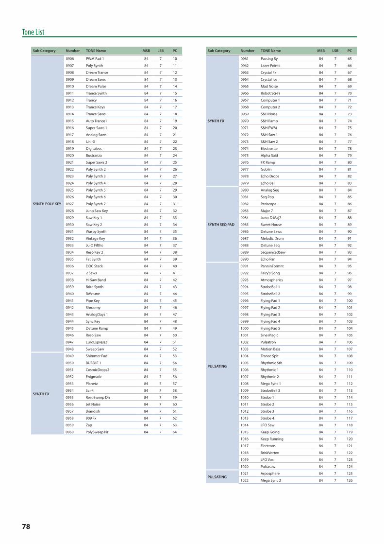
78
Tone List
Sub Category Number TONE Name MSB LSB PC
SYNTH POLY KEY
0906 PWM Pad 1 84 7 10
0907 Poly Synth 84 7 11
0908 Dream Trance 84 7 12
0909 Dream Saws 84 7 13
0910 Dream Pulse 84 7 14
0911 Trance Synth 84 7 15
0912 Trancy 84 7 16
0913 Trance Keys 84 7 17
0914 Trance Saws 84 7 18
0915 Auto Trance1 84 7 19
0916 Super Saws 1 84 7 20
0917 Analog Saws 84 7 21
0918 Uni-G 84 7 22
0919 Digitaless 84 7 23
0920 Bustranza 84 7 24
0921 Super Saws 2 84 7 25
0922 Poly Synth 2 84 7 26
0923 Poly Synth 3 84 7 27
0924 Poly Synth 4 84 7 28
0925 Poly Synth 5 84 7 29
0926 Poly Synth 6 84 7 30
0927 Poly Synth 7 84 7 31
0928 Juno Saw Key 84 7 32
0929 Saw Key 1 84 7 33
0930 Saw Key 2 84 7 34
0931 Waspy Synth 84 7 35
0932 Vintage Key 84 7 36
0933 Ju-D Fifths 84 7 37
0934 Reso Key 2 84 7 38
0935 Fat Synth 84 7 39
0936 DOC Stack 84 7 40
0937 2 Saws 84 7 41
0938 Hi Saw Band 84 7 42
0939 Brite Synth 84 7 43
0940 RAVtune 84 7 44
0941 Pipe Key 84 7 45
0942 Shroomy 84 7 46
0943 AnalogDays 1 84 7 47
0944 Sync Key 84 7 48
0945 Detune Ramp 84 7 49
0946 Reso Saw 84 7 50
0947 EuroExpress3 84 7 51
0948 Sweep Saw 84 7 52
SYNTH FX
0949 Shimmer Pad 84 7 53
0950 BUBBLE 1 84 7 54
0951 CosmicDrops2 84 7 55
0952 Enigmatic 84 7 56
0953 Planetz 84 7 57
0954 Sci-Fi 84 7 58
0955 ResoSweep Dn 84 7 59
0956 Jet Noise 84 7 60
0957 Brandish 84 7 61
0958 909 Fx 84 7 62
0959 Zap 84 7 63
0960 PolySweep Nz 84 7 64
Sub Category Number TONE Name MSB LSB PC
SYNTH FX
0961 Passing By 84 7 65
0962 Lazer Points 84 7 66
0963 Crystal Fx 84 7 67
0964 Crystal Ice 84 7 68
0965 Mad Noise 84 7 69
0966 Robot Sci-Fi 84 7 70
0967 Computer 1 84 7 71
0968 Computer 2 84 7 72
0969 S&H Noise 84 7 73
0970 S&H Ramp 84 7 74
0971 S&H PWM 84 7 75
0972 S&H Saw 1 84 7 76
0973 S&H Saw 2 84 7 77
0974 Electrostar 84 7 78
0975 Alpha Said 84 7 79
0976 FX Ramp 84 7 80
0977 Goblin 84 7 81
0978 Echo Drops 84 7 82
0979 Echo Bell 84 7 83
SYNTH SEQ PAD
0980 Analog Seq 84 7 84
0981 Seq Pop 84 7 85
0982 Periscope 84 7 86
0983 Major 7 84 7 87
0984 Juno-D Maj7 84 7 88
0985 Sweet House 84 7 89
0986 Detune Saws 84 7 90
0987 Melodic Drum 84 7 91
0988 Detune Seq 84 7 92
0989 SequencedSaw 84 7 93
0990 Echo Pan 84 7 94
PULSATING
0991 PanninFormnt 84 7 95
0992 Fairy's Song 84 7 96
0993 Atmospherics 84 7 97
0994 StrobeBell 1 84 7 98
0995 StrobeBell 2 84 7 99
0996 Flying Pad 1 84 7 100
0997 Flying Pad 2 84 7 101
0998 Flying Pad 3 84 7 102
0999 Flying Pad 4 84 7 103
1000 Flying Pad 5 84 7 104
1001 Sine Magic 84 7 105
1002 Pulsatron 84 7 106
1003 Motion Bass 84 7 107
1004 Trance Splt 84 7 108
1005 Rhythmic 5th 84 7 109
1006 Rhythmic 1 84 7 110
1007 Rhythmic 2 84 7 111
1008 Mega Sync 1 84 7 112
1009 StrobeBell 3 84 7 113
1010 Strobe 1 84 7 114
1011 Strobe 2 84 7 115
1012 Strobe 3 84 7 116
1013 Strobe 4 84 7 117
1014 LFO Saw 84 7 118
1015 Keep Going 84 7 119
1016 Keep Running 84 7 120
1017 Electrons 84 7 121
1018 BriskVortex 84 7 122
1019 LFO Vox 84 7 123
1020 Pulsasaw 84 7 124
PULSATING1021 Arposphere 84 7 125
1022 Mega Sync 2 84 7 126
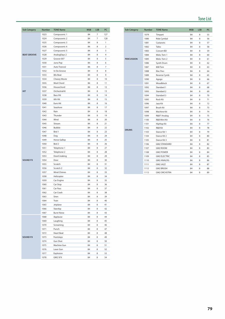
79
Tone List
Sub Category Number TONE Name MSB LSB PC
BEAT GROOVE
1023 Compusonic 1 84 7 127
1024 Compusonic 2 84 7 128
1025 Compusonic 3 84 8 1
1026 Compusonic 4 84 8 2
1027 Compusonic 5 84 8 3
1028 AnalogDays 2 84 8 4
1029 Groove 007 84 8 5
1030 Juno Pop 84 8 6
1031 Auto Trance2 84 8 7
1032 In Da Groove 84 8 8
1033 80s Beat 84 8 9
HIT
1034 Cheezy Movie 84 8 10
1035 Mod Chord 84 8 11
1036 Housechord 84 8 12
1037 OrchestraHit 84 8 13
1038 Bass Hit 84 8 14
1039 6th Hit 84 8 15
1040 Euro Hit 84 8 16
SOUND FX
1041 Seashore 84 8 17
1042 Rain 84 8 18
1043 Thunder 84 8 19
1044 Wind 84 8 20
1045 Stream 84 8 21
1046 Bubble 84 8 22
1047 Bird 1 84 8 23
1048 Dog 84 8 24
1049 Horse Gallop 84 8 25
1050 Bird 2 84 8 26
1051 Telephone 1 84 8 27
1052 Telephone 2 84 8 28
1053 DoorCreaking 84 8 29
1054 Door 84 8 30
1055 Scratch 84 8 31
1056 Scratch 2 84 8 32
1057 Wind Chimes 84 8 33
1058 Helicopter 84 8 34
1059 Car Engine 84 8 35
1060 Car Stop 84 8 36
1061 Car Pass 84 8 37
1062 Car Crash 84 8 38
1063 Siren 84 8 39
1064 Train 84 8 40
1065 Jetplane 84 8 41
1066 Starship 84 8 42
1067 Burst Noise 84 8 43
SOUND FX
1068 Applause 84 8 44
1069 Laughing 84 8 45
1070 Screaming 84 8 46
1071 Punch 84 8 47
1072 Heart Beat 84 8 48
1073 Footsteps 84 8 49
1074 Gun Shot 84 8 50
1075 Machine Gun 84 8 51
1076 Laser Gun 84 8 52
1077 Explosion 84 8 53
1078 GM2 SFX 84 8 54
Sub Category Number TONE Name MSB LSB PC
PERCUSSION
1079 Timpani 84 8 55
1080 Ride Cymbal 84 8 56
1081 Castanets 84 8 57
1082 Taiko 84 8 58
1083 Concert BD 84 8 59
1084 Melo. Tom 1 84 8 60
1085 Melo. Tom 2 84 8 61
1086 Synth Drum 84 8 62
1087 808 Tom 84 8 63
1088 Elec Perc 84 8 64
1089 Reverse Cymb 84 8 65
1090 Agogo 84 8 66
1091 Woodblock 84 8 67
DRUMS
1092 Standard 1 84 8 68
1093 Standard 2 84 8 69
1094 Standard 3 84 8 70
1095 Rock Kit 84 8 71
1096 Jazz Kit 84 8 72
1097 Brush Kit 84 8 73
1098 Machine Kit 84 8 74
1099 R&B T-Analog 84 8 75
1100 R&B Mini Kit 84 8 76
1101 HipHop Kit 84 8 77
1102 R&B Kit 84 8 78
1103 Dance Kit 1 84 8 79
1104 Dance Kit 2 84 8 80
1105 Dance Kit 3 84 8 81
1106 GM2 STANDARD 84 8 82
1107 GM2 ROOM 84 8 83
1108 GM2 POWER 84 8 84
1109 GM2 ELECTRIC 84 8 85
1110 GM2 ANALOG 84 8 86
1111 GM2 JAZZ 84 8 87
1112 GM2 BRUSH 84 8 88
1113 GM2 ORCHSTRA 84 8 89

80
Program List
ABank-Num PROGRAM Name MSB LSB PC
A-01 Solo Jazz Grand 84 64 1
A-02 Honest EP Trem 84 64 2
A-03 FC1 Cry Wah Clav 84 64 3
A-04 Piano + ChoirPad 84 64 4
A-05 Tine EP Menu 84 64 5
A-06 1979 Envelope EP 84 64 6
A-07 1975 Flanger EP 84 64 7
A-08 Studio A Grand 84 64 8
A-09 Phaser Bright EP 84 64 9
A-10 1975 EP Burner 84 64 10
A-11 1975 Soul Ballad 84 64 11
A-12 INITIAL PROGRAM 84 64 12
A-13 INITIAL PROGRAM 84 64 13
A-14 INITIAL PROGRAM 84 64 14
A-15 INITIAL PROGRAM 84 64 15
A-16 INITIAL PROGRAM 84 64 16
A-17 INITIAL PROGRAM 84 64 17
A-18 INITIAL PROGRAM 84 64 18
A-19 INITIAL PROGRAM 84 64 19
A-20 INITIAL PROGRAM 84 64 20
BBank-Num PROGRAM Name MSB LSB PC
B-01 1975 Phased EP 84 64 21
B-02 1979 Sp Echo EP 84 64 22
B-03 Resonant Grand 84 64 23
B-04 1975 M-Phaser EP 84 64 24
B-05 1975 UNI-V EP 84 64 25
B-06 Norwegian Grand 84 64 26
B-07 SR Tine 1979 84 64 27
B-08 SR Tine 1975 84 64 28
B-09 DEMO Stage Grand 84 64 29
B-10 DEMO 1975 Tine 84 64 30
B-11 DEMO 1979 Tine 84 64 31
B-12 INITIAL PROGRAM 84 64 32
B-13 INITIAL PROGRAM 84 64 33
B-14 INITIAL PROGRAM 84 64 34
B-15 INITIAL PROGRAM 84 64 35
B-16 INITIAL PROGRAM 84 64 36
B-17 INITIAL PROGRAM 84 64 37
B-18 INITIAL PROGRAM 84 64 38
B-19 INITIAL PROGRAM 84 64 39
B-20 INITIAL PROGRAM 84 64 40
CBank-Num PROGRAM Name MSB LSB PC
C-01 Piano + Strings 84 64 41
C-02 MFX Tine EP Menu 84 64 42
C-03 Funky Keys Split 84 64 43
C-04 Nice SA E.Piano 84 64 44
C-05 an old Friend... 84 64 45
C-06 Piano + FM EP 84 64 46
C-07 R&B Tine EP Set 84 64 47
C-08 Bs+Ride / Grand 84 64 48
C-09 INITIAL PROGRAM 84 64 49
C-10 INITIAL PROGRAM 84 64 50
C-11 INITIAL PROGRAM 84 64 51
C-12 INITIAL PROGRAM 84 64 52
C-13 INITIAL PROGRAM 84 64 53
C-14 INITIAL PROGRAM 84 64 54
C-15 INITIAL PROGRAM 84 64 55
C-16 INITIAL PROGRAM 84 64 56
C-17 INITIAL PROGRAM 84 64 57
C-18 INITIAL PROGRAM 84 64 58
C-19 INITIAL PROGRAM 84 64 59
C-20 INITIAL PROGRAM 84 64 60
DBank-Num PROGRAM Name MSB LSB PC
D-01 Isn't she ...? 84 64 61
D-02 SlapBs/TWahClav 84 64 62
D-03 Maze of Love 84 64 63
D-04 Silver Top Menu 84 64 64
D-05 1978 ElectricPNO 84 64 65
D-06 StarDust Fantasy 84 64 66
D-07 RvrsPno & Pad 84 64 67
D-08 Telephone Piano 84 64 68
D-09 INITIAL PROGRAM 84 64 69
D-10 INITIAL PROGRAM 84 64 70
D-11 INITIAL PROGRAM 84 64 71
D-12 INITIAL PROGRAM 84 64 72
D-13 INITIAL PROGRAM 84 64 73
D-14 INITIAL PROGRAM 84 64 74
D-15 INITIAL PROGRAM 84 64 75
D-16 INITIAL PROGRAM 84 64 76
D-17 INITIAL PROGRAM 84 64 77
D-18 INITIAL PROGRAM 84 64 78
D-19 INITIAL PROGRAM 84 64 79
D-20 INITIAL PROGRAM 84 64 80

81
Program List
EBank-Num PROGRAM Name MSB LSB PC
E-01 Small Jazz Club 84 64 81
E-02 Rock Organ 84 64 82
E-03 R&B Ballad 84 64 83
E-04 Dyno EP Menu 84 64 84
E-05 Healing Piano 84 64 85
E-06 E.Bass /OrganFst 84 64 86
E-07 CmpPno/AnalogStr 84 64 87
E-08 DEMO Concert Grd 84 64 88
E-09 INITIAL PROGRAM 84 64 89
E-10 INITIAL PROGRAM 84 64 90
E-11 INITIAL PROGRAM 84 64 91
E-12 INITIAL PROGRAM 84 64 92
E-13 INITIAL PROGRAM 84 64 93
E-14 INITIAL PROGRAM 84 64 94
E-15 INITIAL PROGRAM 84 64 95
E-16 INITIAL PROGRAM 84 64 96
E-17 INITIAL PROGRAM 84 64 97
E-18 INITIAL PROGRAM 84 64 98
E-19 INITIAL PROGRAM 84 64 99
E-20 INITIAL PROGRAM 84 64 100
FBank-Num PROGRAM Name MSB LSB PC
F-01 Dist L-Org 84 64 101
F-02 Rox Collection 84 64 102
F-03 Wafting Piano 84 64 103
F-04 Garbage EP 84 64 104
F-05 Dream Keys 84 64 105
F-06 E.Bass /OrganSlw 84 64 106
F-07 SuperLight Piano 84 64 107
F-08 DEMO Tine EP 84 64 108
F-09 INITIAL PROGRAM 84 64 109
F-10 INITIAL PROGRAM 84 64 110
F-11 INITIAL PROGRAM 84 64 111
F-12 INITIAL PROGRAM 84 64 112
F-13 INITIAL PROGRAM 84 64 113
F-14 INITIAL PROGRAM 84 64 114
F-15 INITIAL PROGRAM 84 64 115
F-16 INITIAL PROGRAM 84 64 116
F-17 INITIAL PROGRAM 84 64 117
F-18 INITIAL PROGRAM 84 64 118
F-19 INITIAL PROGRAM 84 64 119
F-20 INITIAL PROGRAM 84 64 120
GBank-Num PROGRAM Name MSB LSB PC
G-01 FC1 PedalWahClav 84 64 121
G-02 TransistorOrgans 84 64 122
G-03 BrightRainyWaltz 84 64 123
G-04 E.Bass/RockPiano 84 64 124
G-05 WaterRing Piano 84 64 125
G-06 DynoEP /SoloLead 84 64 126
G-07 DEMO ToneColor 1 84 64 127
G-08 DEMO ToneColor 2 84 64 128
G-09 INITIAL PROGRAM 84 65 1
G-10 INITIAL PROGRAM 84 65 2
G-11 INITIAL PROGRAM 84 65 3
G-12 INITIAL PROGRAM 84 65 4
G-13 INITIAL PROGRAM 84 65 5
G-14 INITIAL PROGRAM 84 65 6
G-15 INITIAL PROGRAM 84 65 7
G-16 INITIAL PROGRAM 84 65 8
G-17 INITIAL PROGRAM 84 65 9
G-18 INITIAL PROGRAM 84 65 10
G-19 INITIAL PROGRAM 84 65 11
G-20 INITIAL PROGRAM 84 65 12
HBank-Num PROGRAM Name MSB LSB PC
H-01 Reed EP Menu 84 65 13
H-02 History of Tine 84 65 14
H-03 Symphonic Grand 84 65 15
H-04 LA Brass Rock 84 65 16
H-05 E.Bass/RockOrgan 84 65 17
H-06 Re:Milian ScPno 84 65 18
H-07 DEMO Upright Pno 84 65 19
H-08 DEMO SA Piano 84 65 20
H-09 INITIAL PROGRAM 84 65 21
H-10 INITIAL PROGRAM 84 65 22
H-11 INITIAL PROGRAM 84 65 23
H-12 INITIAL PROGRAM 84 65 24
H-13 INITIAL PROGRAM 84 65 25
H-14 INITIAL PROGRAM 84 65 26
H-15 INITIAL PROGRAM 84 65 27
H-16 INITIAL PROGRAM 84 65 28
H-17 INITIAL PROGRAM 84 65 29
H-18 INITIAL PROGRAM 84 65 30
H-19 INITIAL PROGRAM 84 65 31
H-20 INITIAL PROGRAM 84 65 32
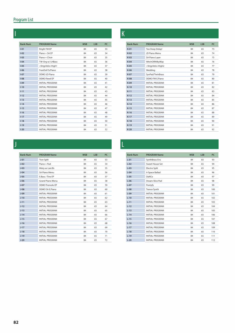
82
Program List
IBank-Num PROGRAM Name MSB LSB PC
I-01 Bright FM EP 84 65 33
I-02 Piano + SA EP 84 65 34
I-03 Piano + Choir 84 65 35
I-04 TW-Org w/ LHBass 84 65 36
I-05 +StrgsVelo>High1 84 65 37
I-06 FranDoll ScPiano 84 65 38
I-07 DEMO JD Piano 84 65 39
I-08 DEMO Reed EP 84 65 40
I-09 INITIAL PROGRAM 84 65 41
I-10 INITIAL PROGRAM 84 65 42
I-11 INITIAL PROGRAM 84 65 43
I-12 INITIAL PROGRAM 84 65 44
I-13 INITIAL PROGRAM 84 65 45
I-14 INITIAL PROGRAM 84 65 46
I-15 INITIAL PROGRAM 84 65 47
I-16 INITIAL PROGRAM 84 65 48
I-17 INITIAL PROGRAM 84 65 49
I-18 INITIAL PROGRAM 84 65 50
I-19 INITIAL PROGRAM 84 65 51
I-20 INITIAL PROGRAM 84 65 52
JBank-Num PROGRAM Name MSB LSB PC
J-01 Tron Split 84 65 53
J-02 Piano + Pad 84 65 54
J-03 Misty as Last.Bs 84 65 55
J-04 SA Piano Menu 84 65 56
J-05 E.Bass / Tine EP 84 65 57
J-06 Grand Piano Menu 84 65 58
J-07 DEMO Tremolo EP 84 65 59
J-08 DEMO SA E.Piano 84 65 60
J-09 INITIAL PROGRAM 84 65 61
J-10 INITIAL PROGRAM 84 65 62
J-11 INITIAL PROGRAM 84 65 63
J-12 INITIAL PROGRAM 84 65 64
J-13 INITIAL PROGRAM 84 65 65
J-14 INITIAL PROGRAM 84 65 66
J-15 INITIAL PROGRAM 84 65 67
J-16 INITIAL PROGRAM 84 65 68
J-17 INITIAL PROGRAM 84 65 69
J-18 INITIAL PROGRAM 84 65 70
J-19 INITIAL PROGRAM 84 65 71
J-20 INITIAL PROGRAM 84 65 72
KBank-Num PROGRAM Name MSB LSB PC
K-01 Too Deep Delay! 84 65 73
K-02 JD Piano Menu 84 65 74
K-03 SA Piano Layer 84 65 75
K-04 WitchOfMilkyWay 84 65 76
K-05 +StrgsVelo>High2 84 65 77
K-06 Wedding 84 65 78
K-07 SynPad/TwinBrass 84 65 79
K-08 DEMO FM E.Piano 84 65 80
K-09 INITIAL PROGRAM 84 65 81
K-10 INITIAL PROGRAM 84 65 82
K-11 INITIAL PROGRAM 84 65 83
K-12 INITIAL PROGRAM 84 65 84
K-13 INITIAL PROGRAM 84 65 85
K-14 INITIAL PROGRAM 84 65 86
K-15 INITIAL PROGRAM 84 65 87
K-16 INITIAL PROGRAM 84 65 88
K-17 INITIAL PROGRAM 84 65 89
K-18 INITIAL PROGRAM 84 65 90
K-19 INITIAL PROGRAM 84 65 91
K-20 INITIAL PROGRAM 84 65 92
LBank-Num PROGRAM Name MSB LSB PC
L-01 SynthBrass Ens 84 65 93
L-02 Sweet House Set 84 65 94
L-03 Electro Split 84 65 95
L-04 4-Space Ballad 84 65 96
L-05 DaNCe 84 65 97
L-06 Dream Slice Pad 84 65 98
L-07 Pontyfy 84 65 99
L-08 Trance Synth 84 65 100
L-09 INITIAL PROGRAM 84 65 101
L-10 INITIAL PROGRAM 84 65 102
L-11 INITIAL PROGRAM 84 65 103
L-12 INITIAL PROGRAM 84 65 104
L-13 INITIAL PROGRAM 84 65 105
L-14 INITIAL PROGRAM 84 65 106
L-15 INITIAL PROGRAM 84 65 107
L-16 INITIAL PROGRAM 84 65 108
L-17 INITIAL PROGRAM 84 65 109
L-18 INITIAL PROGRAM 84 65 110
L-19 INITIAL PROGRAM 84 65 111
L-20 INITIAL PROGRAM 84 65 112

83
Program List
MBank-Num PROGRAM Name MSB LSB PC
M-01 INITIAL PROGRAM 84 65 113
M-02 INITIAL PROGRAM 84 65 114
M-03 INITIAL PROGRAM 84 65 115
M-04 INITIAL PROGRAM 84 65 116
M-05 INITIAL PROGRAM 84 65 117
M-06 INITIAL PROGRAM 84 65 118
M-07 INITIAL PROGRAM 84 65 119
M-08 INITIAL PROGRAM 84 65 120
M-09 INITIAL PROGRAM 84 65 121
M-10 INITIAL PROGRAM 84 65 122
M-11 INITIAL PROGRAM 84 65 123
M-12 INITIAL PROGRAM 84 65 124
M-13 INITIAL PROGRAM 84 65 125
M-14 INITIAL PROGRAM 84 65 126
M-15 INITIAL PROGRAM 84 65 127
M-16 INITIAL PROGRAM 84 65 128
M-17 INITIAL PROGRAM 84 66 1
M-18 INITIAL PROGRAM 84 66 2
M-19 INITIAL PROGRAM 84 66 3
M-20 INITIAL PROGRAM 84 66 4
NBank-Num PROGRAM Name MSB LSB PC
N-01 INITIAL PROGRAM 84 66 5
N-02 INITIAL PROGRAM 84 66 6
N-03 INITIAL PROGRAM 84 66 7
N-04 INITIAL PROGRAM 84 66 8
N-05 INITIAL PROGRAM 84 66 9
N-06 INITIAL PROGRAM 84 66 10
N-07 INITIAL PROGRAM 84 66 11
N-08 INITIAL PROGRAM 84 66 12
N-09 INITIAL PROGRAM 84 66 13
N-10 INITIAL PROGRAM 84 66 14
N-11 INITIAL PROGRAM 84 66 15
N-12 INITIAL PROGRAM 84 66 16
N-13 INITIAL PROGRAM 84 66 17
N-14 INITIAL PROGRAM 84 66 18
N-15 INITIAL PROGRAM 84 66 19
N-16 INITIAL PROGRAM 84 66 20
N-17 INITIAL PROGRAM 84 66 21
N-18 INITIAL PROGRAM 84 66 22
N-19 INITIAL PROGRAM 84 66 23
N-20 INITIAL PROGRAM 84 66 24
OBank-Num PROGRAM Name MSB LSB PC
O-01 INITIAL PROGRAM 84 66 25
O-02 INITIAL PROGRAM 84 66 26
O-03 INITIAL PROGRAM 84 66 27
O-04 INITIAL PROGRAM 84 66 28
O-05 INITIAL PROGRAM 84 66 29
O-06 INITIAL PROGRAM 84 66 30
O-07 INITIAL PROGRAM 84 66 31
O-08 INITIAL PROGRAM 84 66 32
O-09 INITIAL PROGRAM 84 66 33
O-10 INITIAL PROGRAM 84 66 34
O-11 INITIAL PROGRAM 84 66 35
O-12 INITIAL PROGRAM 84 66 36
O-13 INITIAL PROGRAM 84 66 37
O-14 INITIAL PROGRAM 84 66 38
O-15 INITIAL PROGRAM 84 66 39
O-16 INITIAL PROGRAM 84 66 40
O-17 INITIAL PROGRAM 84 66 41
O-18 INITIAL PROGRAM 84 66 42
O-19 INITIAL PROGRAM 84 66 43
O-20 INITIAL PROGRAM 84 66 44


