Physical Property Measurement System
Horizontal Rotator Option User’s Manual
Part Number 1384-100B
Quantum Design 11578 Sorrento Valley Rd. San Diego, CA 92121-1311 USA Technical support (858) 481-4400 (800) 289-6996 Fax (858) 481-7410 Second edition of manual completed June 2000.
Trademarks All product and company names appearing in this manual are trademarks or registered trademarks of their respective holders.
U.S. Patents 4,791,788 Method for Obtaining Improved Temperature Regulation When Using Liquid Helium Cooling 4,848,093 Apparatus and Method for Regulating Temperature in a Cryogenic Test Chamber 5,311,125 Magnetic Property Characterization System Employing a Single Sensing Coil Arrangement to Measure AC
Susceptibility and DC Moment of a Sample (patent licensed from Lakeshore) 5,647,228 Apparatus and Method for Regulating Temperature in Cryogenic Test Chamber 5,798,641 Torque Magnetometer Utilizing Integrated Piezoresistive Levers
Foreign Patents U.K. 9713380.5 Apparatus and Method for Regulating Temperature in Cryogenic Test Chamber
Quantum Design PPMS Horizontal Rotator Option User’s Manual i
C O N T E N T S
Table of Contents PREFACE Contents and Conventions .................................................................................................................................v
P.1 Introduction ........................................................................................................................................................v P.2 Scope of the Manual...........................................................................................................................................v P.3 Contents of the Manual ......................................................................................................................................v P.4 Conventions in the Manual................................................................................................................................vi
CHAPTER 1 Introduction .......................................................................................................................................................1-1
1.1 Introduction ...................................................................................................................................................1-1 1.2 Overview of the Horizontal Rotator Option ..................................................................................................1-1
1.2.1 Manual and Automatic Operation ..........................................................................................................1-2 1.2.2 Electrical Connection to the Model 6000 ...............................................................................................1-2 1.2.3 Maintenance ...........................................................................................................................................1-3
1.3 Horizontal Rotator Probe...............................................................................................................................1-4 1.3.1 Current Leads .........................................................................................................................................1-5 1.3.2 Rotator Thermometer..............................................................................................................................1-5 1.3.3 Changing the Orientation of the Sample Holder Board..........................................................................1-6
CHAPTER 2 Installation..........................................................................................................................................................2-1
2.1 Introduction ...................................................................................................................................................2-1 2.2 Overview of Horizontal Rotator Installation .................................................................................................2-1 2.3 Mounting the Sample on the Sample Holder Board ......................................................................................2-2
2.3.1 Step 1: Secure the Sample ......................................................................................................................2-2 2.3.2 Step 2: Wire the Sample .........................................................................................................................2-2
2.4 Attaching the Sample Holder Board to the Rotator.......................................................................................2-3 2.5 Installing the Horizontal Rotator Hardware ..................................................................................................2-5 2.6 Downloading the Rotator Configuration Files ..............................................................................................2-7 2.7 Ensuring Proper Position Calibration ............................................................................................................2-8 2.8 Removing the Horizontal Rotator Hardware.................................................................................................2-9
CHAPTER 3 Rotator Motor Operation.............................................................................................................................3-1
3.1 Introduction ...................................................................................................................................................3-1 3.2 Controlling the Rotator Motor.......................................................................................................................3-1
3.2.1 Status Information ..................................................................................................................................3-1 3.2.2 Movement Control Commands in Immediate Mode ..............................................................................3-2 3.2.3 Movement Control Commands in Sequence Mode ................................................................................3-2
3.3 Setting the Position Configuration Parameters..............................................................................................3-4 3.4 Measurement Considerations ........................................................................................................................3-5
Contents Table of Contents
ii PPMS Horizontal Rotator Option User’s Manual Quantum Design
APPENDIX A PPMS Firmware Commands ..................................................................................................................... A-1
A.1 Introduction .................................................................................................................................................A-1 A.2 PPMS Firmware Command Tree.................................................................................................................A-1 A.3 Function of PPMS Firmware Commands ....................................................................................................A-2
A.3.1 PPMS Firmware Setup Commands ......................................................................................................A-2 A.3.1.1 Model 6000 Position Configuration Commands ...........................................................................A-2
A.3.2 PPMS Firmware Immediate Operation Command ...............................................................................A-2 A.3.3 PPMS Firmware Interactive Control Commands .................................................................................A-3
APPENDIX B Interconnection Tables ................................................................................................................................. B-1
B.1 Introduction.................................................................................................................................................. B-1 B.2 Standard Interconnection Table ................................................................................................................... B-1 B.3 Interconnection Tables for the ACT/Horizontal Rotator Probe Cable.........................................................B-2 B.4 Motor Interconnection Table ....................................................................................................................... B-3
References..............................................................................................................................................References-1 Index ................................................................................................................................................................ Index-1
Contents Table of Figures
Quantum Design PPMS Horizontal Rotator Option User’s Manual iii
Figures Figure 1-1. Connection Diagram for Horizontal Rotator ........................................................................................1-2 Figure 1-2. Horizontal Rotator Probe ......................................................................................................................1-4 Figure 2-1. Resistance Bridge Sample Holder Board...............................................................................................2-2 Figure 2-2. Rotator Support Tool ............................................................................................................................2-3 Figure 2-3. Sample Removal Tool ..........................................................................................................................2-3 Figure 2-4. Correct Orientation of Rotator Transfer Case on Rotator Support Tool...............................................2-4 Figure 2-5. Placing the Sample Holder Board on the Rotator Platform Circuit Board ...........................................2-4 Figure 2-6. Horizontal Rotator Support Plate and Motor ........................................................................................2-6 Figure 3-1. Motion Control Dialog Box..................................................................................................................3-2 Figure 3-2. Set Position Dialog Box .......................................................................................................................3-3 Figure 3-3. Scan Position Dialog Box ....................................................................................................................3-3 Figure 3-4. Position Configuration Dialog Box ......................................................................................................3-4 Figure A-1. Model 6000 Firmware Command Tree...............................................................................................A-1
Contents Table of Tables
iv PPMS Horizontal Rotator Option User’s Manual Quantum Design
Tables Table 1-1. Hardware for Horizontal Rotator Option ...............................................................................................1-1 Table 1-2. Part Numbers for Horizontal Rotator Parts and Accessories .................................................................1-3 Table 2-1. Standard Interconnection Table for Horizontal Rotator.........................................................................2-3 Table 2-2. Types of Rotator Configuration Files.....................................................................................................2-7 Table 3-1. Immediate-Mode Movement Control Commands..................................................................................3-2 Table 3-2. Set Position Sequence Command Movement Modes.............................................................................3-3 Table 3-3. Parameters for Scan Position Sequence Command................................................................................3-3 Table A-1. Position Configuration Parameters for Motion Control Variables.......................................................A-2 Table A-2. Options in Move Positioner Screen......................................................................................................A-2 Table A-3. Move Positioner Screen Modes............................................................................................................A-3 Table B-1. Standard Interconnection Table for Horizontal Rotator ....................................................................... B-1 Table B-2. Pin Mapping for P2−System Bridge Port on Model 6000.................................................................... B-2 Table B-3. Pin Mapping for P1−Sample Current Out Port on Model 7100 ........................................................... B-2 Table B-4. Pin Mapping for P5−Sample Voltage In Port on Model 7100 ............................................................. B-2 Table B-5. Motor Interconnection Table ................................................................................................................ B-3
Quantum Design PPMS Horizontal Rotator Option User’s Manual v
P R E F A C E
Contents and Conventions
P.1 Introduction This preface contains the following information:
• Section P.2 discusses the overall scope of the manual.
• Section P.4 illustrates and describes conventions that appear in the manual.
• Section P.3 briefly summarizes the contents of the manual.
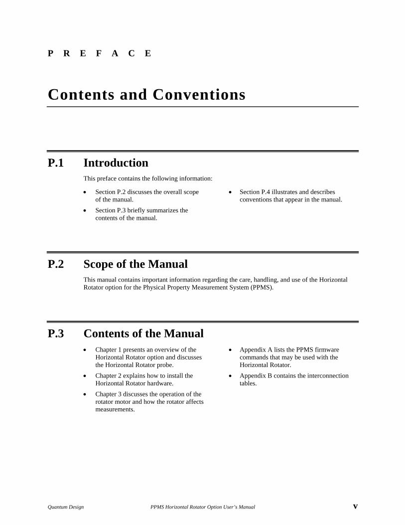
P.2 Scope of the Manual This manual contains important information regarding the care, handling, and use of the Horizontal Rotator option for the Physical Property Measurement System (PPMS).
P.3 Contents of the Manual • Chapter 1 presents an overview of the
Horizontal Rotator option and discusses the Horizontal Rotator probe.
• Appendix A lists the PPMS firmware commands that may be used with the Horizontal Rotator.
• Chapter 2 explains how to install the Horizontal Rotator hardware.
• Appendix B contains the interconnection tables.
• Chapter 3 discusses the operation of the rotator motor and how the rotator affects measurements.
Section P.4 Preface Conventions in the Manual Contents and Conventions
vi PPMS Horizontal Rotator Option User’s Manual Quantum Design
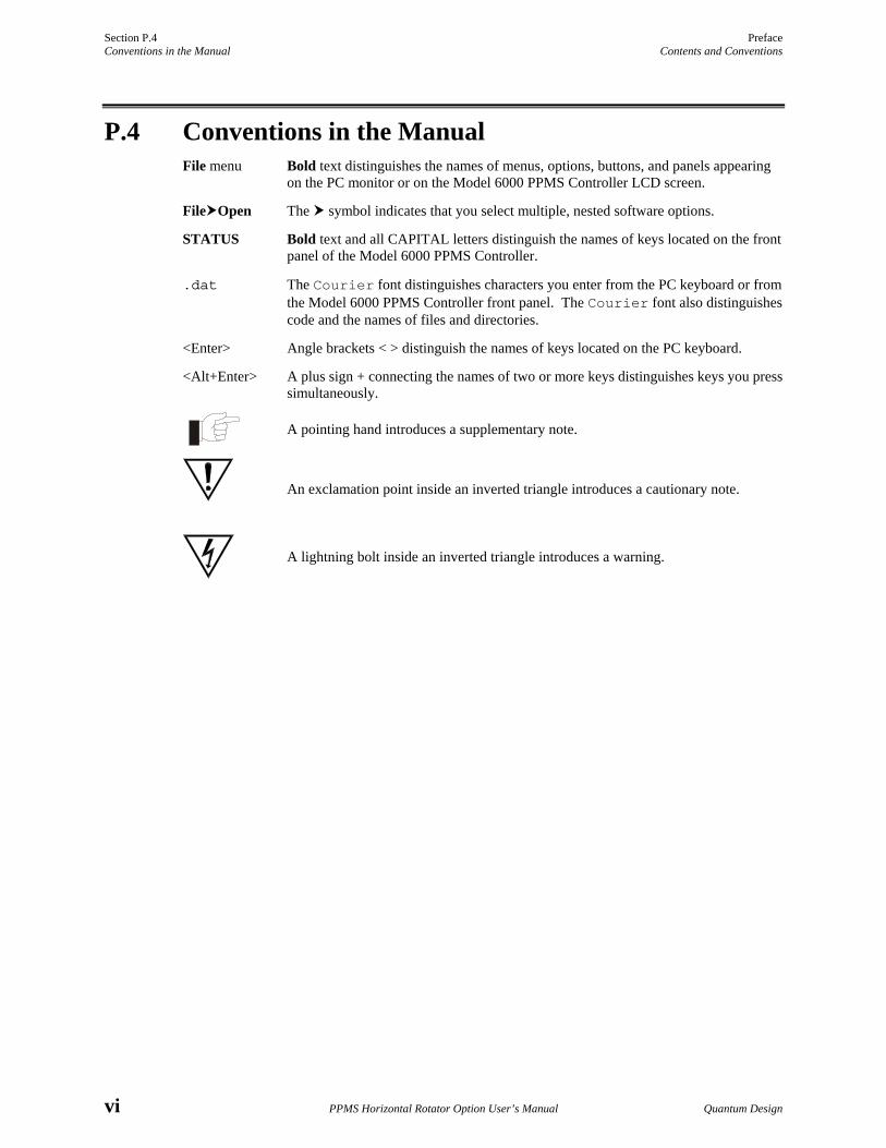
P.4 Conventions in the Manual File menu Bold text distinguishes the names of menus, options, buttons, and panels appearing
on the PC monitor or on the Model 6000 PPMS Controller LCD screen.
File Open The symbol indicates that you select multiple, nested software options.
STATUS Bold text and all CAPITAL letters distinguish the names of keys located on the front panel of the Model 6000 PPMS Controller.
.dat The Courier font distinguishes characters you enter from the PC keyboard or from the Model 6000 PPMS Controller front panel. The Courier font also distinguishes code and the names of files and directories.
<Enter> Angle brackets < > distinguish the names of keys located on the PC keyboard.
<Alt+Enter> A plus sign + connecting the names of two or more keys distinguishes keys you press simultaneously.
A pointing hand introduces a supplementary note.
An exclamation point inside an inverted triangle introduces a cautionary note.
A lightning bolt inside an inverted triangle introduces a warning.
Quantum Design PPMS Horizontal Rotator Option User’s Manual 1-1
C H A P T E R 1
Introduction
1.1 Introduction This chapter contains the following information:
• Section 1.2 presents an overview of the PPMS Horizontal Rotator option.
• Section 1.3 discusses operation of the Horizontal Rotator probe.
1.2 Overview of the Horizontal Rotator Option The Quantum Design Horizontal Rotator option for the Physical Property Measurement System (PPMS) allows sample rotations around an axis that is perpendicular to the magnetic field of a longitudinal PPMS magnet. The Horizontal Rotator probe fits into the PPMS sample chamber with all wiring connections accomplished via the keyed connector at the bottom of the sample chamber. The rotator may safely be exposed to all temperatures accessible in the PPMS.
The range of rotator rotation is −10° to 370°. For Horizontal Rotators with serial numbers 011 or greater, 0° and 360° denote the face-up orientation. For Horizontal Rotators with serial numbers 001 to 010, 0° and 360° denote the face-down orientation, and 180° denotes the face-up orientation. An anti-backlash spring helps keep the same gear faces in contact at all times. For the standard rotator motor, the motorized steps are in .0532° increments, and the maximum rate of rotation is 10° per second. For the high-resolution motor, the motorized steps are in 0.00449° increments, and the maximum rate of rotation is about 50° per minute. Jewel bearings on the moving parts lengthen the life span of the rotator.
Table 1-1. Hardware for Horizontal Rotator Option
HARDWARE PART NUMBER ILLUSTRATION
Horizontal Rotator Probe 4084-304 Figure 1-2
Resistance Bridge Sample Holder Board 3084-371 Figure 2-1
Support Plate with Motor 4084-302 Figure 2-6
Rotator Support Tool 4084-391 Figure 2-2
Sample Removal Tool 4084-307 Figure 2-3
Horizontal Rotator Kit for ACT Option 4084-308
Section 1.2 Chapter 1 Overview of the Horizontal Rotator Option Introduction
1-2 PPMS Horizontal Rotator Option User’s Manual Quantum Design
The Horizontal Rotator option may be used with the PPMS AC Transport Measurement System (ACT) option or the PPMS Resistivity option. For detailed information about using the rotator with either of these options, refer to the Physical Property Measurement System: AC Transport Option User’s Manual or the Physical Property Measurement System: Resistivity Option User’s Manual.
1.2.1 Manual and Automatic Operation The Horizontal Rotator may be operated manually or used with an automatic motor drive. The vernier dial on the top of the Horizontal Rotator probe may be turned manually, or the motor connected to the support plate can mate with the top of the rotator to control sample orientation. The Instrument Motion menu option in PPMS MultiVu allows immediate access to motor control and configuration. Sequence commands can automate motor control through the use of PPMS sequences. Section 3.2.2 discusses immediate-mode operation. Section 3.2.3 discusses sequence mode operation. Appendix A lists the firmware commands that affect the Horizontal Rotator. The Physical Property Measurement System: Firmware Manual explains in more detail how to control the motor directly from the front panel of the Model 6000 PPMS Controller.
The manually operated rotator consists of the Horizontal Rotator probe and the support plate assembly without a motor.
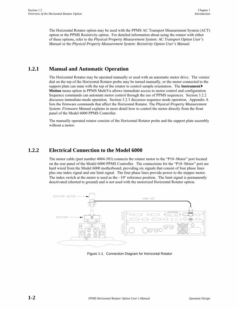
1.2.2 Electrical Connection to the Model 6000 The motor cable (part number 4084-303) connects the rotator motor to the “P10−Motor” port located on the rear panel of the Model 6000 PPMS Controller. The connections for the “P10−Motor” port are hard wired from the Model 6000 motherboard, providing six signals that consist of four phase lines plus one index signal and one limit signal. The four phase lines provide power to the stepper motor. The index switch at the motor is used as the −10° reference position. The limit signal is permanently deactivated (shorted to ground) and is not used with the motorized Horizontal Rotator option.
Figure 1-1. Connection Diagram for Horizontal Rotator
Chapter 1 Section 1.2 Introduction Overview of the Horizontal Rotator Option
Quantum Design PPMS Horizontal Rotator Option User’s Manual 1-3
1.2.3 Maintenance The rotator O-rings should be kept clean and lubricated to ensure long life for the PPMS. The O-rings on the top end of the Horizontal Rotator probe (see figure 1-2) should be lubricated with Apiezon M Grease. The O-rings on the bottom of the rotator support plate (see figure 2-6) should be lubricated with silicone vacuum grease. Both greases can be obtained from Quantum Design. Gears, bearings, and other moving parts on the rotator should not come in contact with grease.
Heat sink compound is applied to the top of the rotator thermometer to help keep it in close thermal contact with the sample holder board. Fresh thermal compound should be applied when there is no visible amount of compound left on the thermometer. This thermal compound can also be obtained from Quantum Design.
Table 1-2. Part Numbers for Horizontal Rotator Parts and Accessories
DESCRIPTION PART NUMBER ILLUSTRATION
O-ring for Horizontal Rotator Probe VON-218 Figure 1-2
O-ring for Support Plate VON2-326 Figure 2-6
Apiezon M Grease (for VON-218) HM11
Silicone Vacuum Grease (for VON2-326) AGV1
Thermal Compound for Rotator Thermometer AGT1
Rotator Support Tool 4084-391 Figure 2-2
Sample Removal Tool 4084-307 Figure 2-3
Resistance Bridge Sample Holder Board 3084-371 Figure 2-1
Universal Sample Holder Board 3084-341 Figure 2-5
AC Transport Sample Holder Board 3084-370
Horizontal Rotator Kit for ACT Option • Includes ACT/Horizontal Rotator Probe Cable • Includes ACT Sample Holder Board
4084-308 3084-517 3084-370
Prices for parts listed in table 1-2 can be obtained by contacting Quantum Design’s Customer Service Department. Some parts may also be obtained through other vendors.
Section 1.3 Chapter 1 Horizontal Rotator Probe Introduction
1-4 PPMS Horizontal Rotator Option User’s Manual Quantum Design
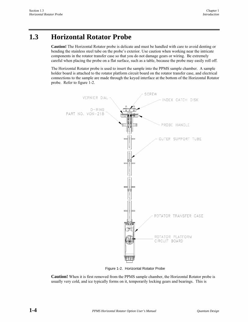
1.3 Horizontal Rotator Probe Caution! The Horizontal Rotator probe is delicate and must be handled with care to avoid denting or bending the stainless steel tube on the probe’s exterior. Use caution when working near the intricate components in the rotator transfer case so that you do not damage gears or wiring. Be extremely careful when placing the probe on a flat surface, such as a table, because the probe may easily roll off.
The Horizontal Rotator probe is used to insert the sample into the PPMS sample chamber. A sample holder board is attached to the rotator platform circuit board on the rotator transfer case, and electrical connections to the sample are made through the keyed interface at the bottom of the Horizontal Rotator probe. Refer to figure 1-2.
Figure 1-2. Horizontal Rotator Probe
Caution! When it is first removed from the PPMS sample chamber, the Horizontal Rotator probe is usually very cold, and ice typically forms on it, temporarily locking gears and bearings. This is
Chapter 1 Section 1.3 Introduction Horizontal Rotator Probe
Quantum Design PPMS Horizontal Rotator Option User’s Manual 1-5
normal. Do not force rotator motion when the rotator is in this condition. The rotator thaws within 1 or 2 minutes, and you may gently work the index catch disk to verify rotation.
Caution! Do not store the Horizontal Rotator probe so that it hangs upside down, and do not rotate the rotator upside down. When the rotator is upside down, the metal pin that prevents the rotator from moving beyond −10° or 370° falls out. This problem can normally be fixed by turning the probe right-side up and rotating it back and forth a few times.
When not in use, the Horizontal Rotator probe should be stored in a vertical position in a hanging rack.
The O-rings on the top end of the Horizontal Rotator probe should periodically be lubricated with grease. Refer to section 1.2.3.
1.3.1 Current Leads Four copper alloy current leads are wired to the rotator platform circuit board. These leads are connected to contact pads 7, 8, 11, and 12 as labeled on the resistance bridge sample holder board. The remainders of the leads are phosphor-bronze and should only be used for voltage detection.
Caution! The current leads on the rotator (7, 8, 11, and 12) are fine-gauge copper alloy. They are rated for a maximum .500A current. It is possible to output up to 2A current by using the ACT option with the rotator. Depending on temperature and other conditions, this may overheat and melt the rotator wiring. To avoid this situation, limit your output current to .500A while using ACT with the rotator. At room temperature the resistance of the rotator current leads is roughly 0.5 Ω.
Note: Quantum Design doesn’t guarantee the rotator wiring for any current above .500A. However, it is possible to perform experiments with greater current by limiting measurement duration and introducing a cooling period between measurements. Call Quantum Design customer service for details.
1.3.2 Rotator Thermometer The rotator thermometer is wired to contact pads 3 through 6. User bridge board channel 1 reads the rotator thermometer unless the ACT option is in use. When the ACT option is in use, system bridge board channel 4 reads the rotator thermometer.
When the rotator is being used, the settings for user bridge board channel 1 should not be changed from their normal settings for the rotator. These settings are 1000 µA current limit, 100 µW power limit, and 10 mV voltage limit. Exceeding these limits can damage the thermometer. Because this thermometer is used by the Model 6000 as the user thermometer that controls system temperature, you must avoid wiring samples in parallel with the rotator thermometer. Doing so eliminates the ability to accurately read the rotator thermometer and causes erroneous sample measurements.
Heat sink compound is applied to the top of the rotator thermometer. Refer to section 1.2.3.
Section 1.3 Chapter 1 Horizontal Rotator Probe Introduction
1-6 PPMS Horizontal Rotator Option User’s Manual Quantum Design
1.3.3 Changing the Orientation of the Sample Holder Board To change the angular orientation of the sample holder board that is mounted on the rotator platform circuit board, you use only the index catch disk at the top of the Horizontal Rotator probe. Do not force rotation of the sample holder board itself. The index catch disk is intentionally left loose enough to slip when the rotator has reached its physical limits. This is to prevent damage to the delicate com-ponents of the rotator should the motor attempt to move the rotator beyond its physical limits. If the index catch disk is too loose, you may tighten the set screw within this disk by using a 1/16-inch ball driver or Allen wrench. Do not disable this safety disengagement mechanism by gluing or otherwise permanently attaching the index catch disk.
Quantum Design PPMS Horizontal Rotator Option User’s Manual 2-1
C H A P T E R 2
Installation
2.1 Introduction This chapter contains the following information:
• Section 2.2 summarizes the rotator hardware installation procedures.
• Section 2.6 explains how to download the rotator configuration files.
• Section 2.3 explains how to mount a sample on a sample holder board.
• Section 2.7 explains how to ensure proper position calibration.
• Section 2.4 explains how to attach a sample holder board to the rotator probe.
• Section 2.8 explains how to remove the rotator hardware from the PPMS.
• Section 2.5 explains how to install the rotator hardware into the PPMS.
2.2 Overview of Horizontal Rotator Installation You must complete the following procedures before you may take measurements with the Horizontal Rotator.
1. Mount the sample on a sample holder board (section 2.3). 2. Attach the sample holder board to the Horizontal Rotator probe (section 2.4). 3. Install the Horizontal Rotator hardware in the PPMS (section 2.5). 4. Download the appropriate rotator configuration file (section 2.6). 5. Engage the motor and check for proper position calibration (section 2.7).
If you want to simply attach a different sample to the Horizontal Rotator probe without completely removing the rotator hardware from the PPMS, you may omit steps 4 and 5 above unless you perceive problems with rotator operation, in which case these should be your first two lines of action.
Before taking measurements, you should refer to section 3.4, “Measurement Considerations.”
Section 2.3 Chapter 2 Mounting the Sample on the Sample Holder Board Installation
2-2 PPMS Horizontal Rotator Option User’s Manual Quantum Design
2.3 Mounting the Sample on the Sample Holder Board The sample is mounted on a sample holder board (see figure 2-1), which is then attached to the rotator platform circuit board on the Horizontal Rotator probe. The sample should be smaller than 8 × 9 mm so that the sample holder board can be mounted on the rotator platform. The sample holder board makes thermal contact with a thermometer on the rotator platform, allowing close monitoring of the sample temperature when the sample is installed in the PPMS sample chamber. Electrical connections to the mounted sample are made through contact pads on the sample holder board.
To mount a sample on a sample holder board, you (1) secure the sample to the sample holder board and then (2) wire the sample to the sample holder board.
2.3.1 Step 1: Secure the Sample You may use a variety of techniques, including tapes, glues, greases, and epoxies, to secure samples to the sample holder board. The method you use to secure a sample must be able to withstand the entire temperature range to which the sample will be subjected.
2.3.2 Step 2: Wire the Sample Electrical contact to the sample is made by using the labeled contact pads on the sample holder board. You typically solder leads to these pads. You may wire samples permanently to the sample holder board and then install the sample holder board on the rotator when you are ready to use the sample.
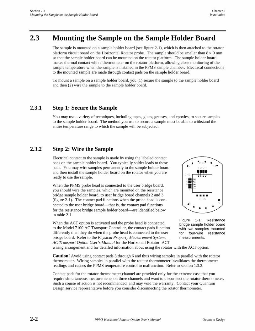
When the PPMS probe head is connected to the user bridge board, you should wire the samples, which are mounted on the resistance bridge sample holder board, to user bridge board channels 2 and 3 (figure 2-1). The contact pad functions when the probe head is con-nected to the user bridge board⎯that is, the contact pad functions for the resistance bridge sample holder board⎯are identified below in table 2-1.
When the ACT option is activated and the probe head is connected to the Model 7100 AC Transport Controller, the contact pads function differently than they do when the probe head is connected to the user bridge board. Refer to the Physical Property Measurement System: AC Transport Option User’s Manual for the Horizontal Rotator−ACT wiring arrangement and for detailed information about using the rotator with the ACT option.
Caution! Avoid using contact pads 3 through 6 and thus wiring samples in parallel with the rotator thermometer. Wiring samples in parallel with the rotator thermometer invalidates the thermometer readings and causes the PPMS temperature control to malfunction. Refer to section 1.3.2.
Contact pads for the rotator thermometer channel are provided only for the extreme case that you require simultaneous measurements on three channels and want to disconnect the rotator thermometer. Such a course of action is not recommended, and may void the warranty. Contact your Quantum Design service representative before you consider disconnecting the rotator thermometer.
Figure 2-1. Resistance bridge sample holder board with two samples mounted for four-wire resistance measurements.
Chapter 2 Section 2.4 Installation Attaching the Sample Holder Board to the Rotator
Quantum Design PPMS Horizontal Rotator Option User’s Manual 2-3
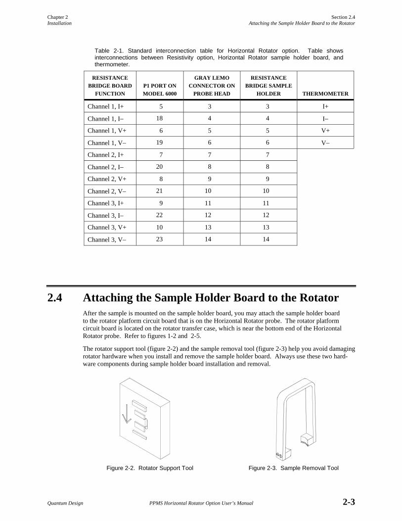
Table 2-1. Standard interconnection table for Horizontal Rotator option. Table shows interconnections between Resistivity option, Horizontal Rotator sample holder board, and thermometer.
RESISTANCE BRIDGE BOARD
FUNCTION
P1 PORT ON MODEL 6000
GRAY LEMO CONNECTOR ON
PROBE HEAD
RESISTANCE BRIDGE SAMPLE
HOLDER
THERMOMETER
Channel 1, I+ 5 3 3 I+
Channel 1, I− 18 4 4 I−
Channel 1, V+ 6 5 5 V+
Channel 1, V− 19 6 6 V−
Channel 2, I+ 7 7 7
Channel 2, I− 20 8 8
Channel 2, V+ 8 9 9
Channel 2, V− 21 10 10
Channel 3, I+ 9 11 11
Channel 3, I− 22 12 12
Channel 3, V+ 10 13 13
Channel 3, V− 23 14 14
2.4 Attaching the Sample Holder Board to the Rotator After the sample is mounted on the sample holder board, you may attach the sample holder board to the rotator platform circuit board that is on the Horizontal Rotator probe. The rotator platform circuit board is located on the rotator transfer case, which is near the bottom end of the Horizontal Rotator probe. Refer to figures 1-2 and 2-5.
The rotator support tool (figure 2-2) and the sample removal tool (figure 2-3) help you avoid damaging rotator hardware when you install and remove the sample holder board. Always use these two hard-ware components during sample holder board installation and removal.
Figure 2-2. Rotator Support Tool Figure 2-3. Sample Removal Tool
Section 2.4 Chapter 2 Attaching the Sample Holder Board to the Rotator Installation
2-4 PPMS Horizontal Rotator Option User’s Manual Quantum Design
Complete the following steps to attach the sample holder board to the rotator:
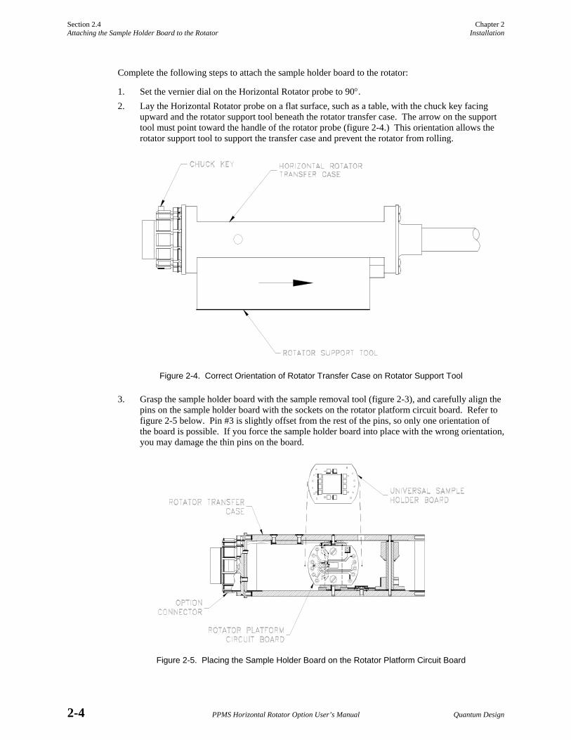
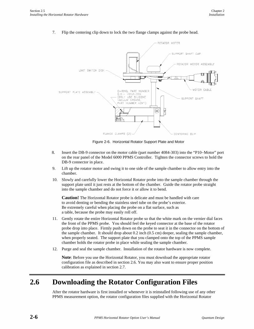
1. Set the vernier dial on the Horizontal Rotator probe to 90°. 2. Lay the Horizontal Rotator probe on a flat surface, such as a table, with the chuck key facing
upward and the rotator support tool beneath the rotator transfer case. The arrow on the support tool must point toward the handle of the rotator probe (figure 2-4.) This orientation allows the rotator support tool to support the transfer case and prevent the rotator from rolling.
Figure 2-4. Correct Orientation of Rotator Transfer Case on Rotator Support Tool
3. Grasp the sample holder board with the sample removal tool (figure 2-3), and carefully align the pins on the sample holder board with the sockets on the rotator platform circuit board. Refer to figure 2-5 below. Pin #3 is slightly offset from the rest of the pins, so only one orientation of the board is possible. If you force the sample holder board into place with the wrong orientation, you may damage the thin pins on the board.
Figure 2-5. Placing the Sample Holder Board on the Rotator Platform Circuit Board
Chapter 2 Section 2.5 Installation Installing the Horizontal Rotator Hardware
Quantum Design PPMS Horizontal Rotator Option User’s Manual 2-5
Caution! Use the sample removal tool like a set of tweezers to grasp the sample holder board when you insert the sample holder board on or remove it from the rotator platform. The sample removal tool ensures that even pressure is applied to the sample holder board, therefore keeping the thin pins on the bottom of the sample holder board from bending. Using your fingers to press the sample holder board onto the rotator may bend the pins and damage the electrical connections to the sample.
4. Continue to grasp the sample holder board with the sample removal tool, and then use the sample removal tool to push down the sample holder board completely so that it is immediately on top of the rotator platform circuit board. If the sample holder board is not pushed in with even pressure applied across the board, it may go in crooked and damage the pins. The sample holder board should contact the rotator thermometer with a little thermal compound on top of the thermom-eter. Once the sample holder board is properly attached, the rotator probe is ready to be installed in the PPMS.
To remove the sample from the rotator probe, follow essentially the same procedure above, being sure you gently pull the sample holder board out of place by using the sample removal tool.
Refer to section 1.3.3 to change the angular orientation of a sample holder board that is attached to the rotator probe.
2.5 Installing the Horizontal Rotator Hardware The following procedure explains how you install the Horizontal Rotator support plate and Horizontal Rotator probe in the PPMS. Section 2.3 explains how you mount a sample on a sample holder board, and section 2.4 explains how you attach the sample holder board to the Horizontal Rotator probe.
Caution! Before you open the sample chamber to the atmosphere, always verify that it is at or above room temperature. If you open the sample chamber while it is below room temperature, condensation and cryopumping of air constituents may occur. This can ultimately cause sample tube deformation and loss of temperature control. 1. Set the PPMS temperature to 298 K, and wait for the temperature to stabilize. 2. Vent the sample chamber continuously. 3. Open the sample chamber and remove any sample puck or PPMS option currently installed in
the chamber. Refer to the Physical Property Measurement System: Hardware Manual or to the appropriate option manual.
4. Verify that the user bridge cable (part number 3084-003) or the ACT/Horizontal Rotator probe cable (part number 3084-517) is connected (a) to the gray, color-coded port on the PPMS probe head and (b) to other ports as appropriate. For specific information about the user bridge cable, refer to the Physical Property Measurement System: Resistivity Option User’s Manual. For specific information about the ACT/Horizontal Rotator probe cable, refer to the Physical Property Measurement System: AC Transport Option User’s Manual.
5. Place the rotator support plate (figure 2-6) over the PPMS probe head with the centering clip towards the rear of the probe⎯that is, towards the cable connections.
6. Keep the centering clip up, and firmly squeeze the two flange clamps (figure 2-6) together until they click into place, locking the support plate onto the flange on top of the probe head. You may temporarily remove one or both relief valves from the PPMS helium fill ports to afford easier access for the flange clamps.
Section 2.5 Chapter 2 Installing the Horizontal Rotator Hardware Installation
2-6 PPMS Horizontal Rotator Option User’s Manual Quantum Design
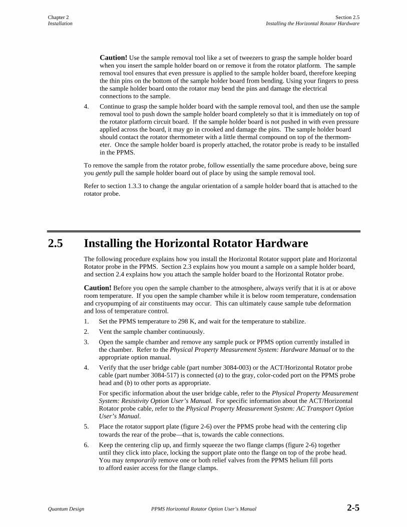
7. Flip the centering clip down to lock the two flange clamps against the probe head.
Figure 2-6. Horizontal Rotator Support Plate and Motor
8. Insert the DB-9 connector on the motor cable (part number 4084-303) into the “P10−Motor” port on the rear panel of the Model 6000 PPMS Controller. Tighten the connector screws to hold the DB-9 connector in place.
9. Lift up the rotator motor and swing it to one side of the sample chamber to allow entry into the chamber.
10. Slowly and carefully lower the Horizontal Rotator probe into the sample chamber through the support plate until it just rests at the bottom of the chamber. Guide the rotator probe straight into the sample chamber and do not force it or allow it to bend.
Caution! The Horizontal Rotator probe is delicate and must be handled with care to avoid denting or bending the stainless steel tube on the probe’s exterior. Be extremely careful when placing the probe on a flat surface, such as a table, because the probe may easily roll off.
11. Gently rotate the entire Horizontal Rotator probe so that the white mark on the vernier dial faces the front of the PPMS probe. You should feel the keyed connector at the base of the rotator probe drop into place. Firmly push down on the probe to seat it in the connector on the bottom of the sample chamber. It should drop about 0.2 inch (0.5 cm) deeper, sealing the sample chamber, when properly seated. The support plate that you clamped onto the top of the PPMS sample chamber holds the rotator probe in place while sealing the sample chamber.
12. Purge and seal the sample chamber. Installation of the rotator hardware is now complete.
Note: Before you use the Horizontal Rotator, you must download the appropriate rotator configuration file as described in section 2.6. You may also want to ensure proper position calibration as explained in section 2.7.
2.6 Downloading the Rotator Configuration Files After the rotator hardware is first installed or whenever it is reinstalled following use of any other PPMS measurement option, the rotator configuration files supplied with the Horizontal Rotator
Chapter 2 Section 2.6 Installation Downloading the Rotator Configuration Files
Quantum Design PPMS Horizontal Rotator Option User’s Manual 2-7
must be downloaded. Downloading the rotator configuration files ensures that the Model 6000 PPMS Controller uses the proper motor configuration and thermometer calibration.
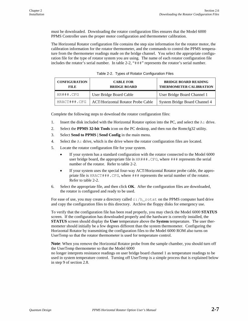
The Horizontal Rotator configuration file contains the step size information for the rotator motor, the calibration information for the rotator thermometer, and the commands to control the PPMS tempera-ture from the thermometer readings made on the bridge channel. You select the appropriate configu-ration file for the type of rotator system you are using. The name of each rotator configuration file includes the rotator’s serial number. In table 2-2, “###” represents the rotator’s serial number.
Table 2-2. Types of Rotator Configuration Files
CONFIGURATIONFILE
CABLE FOR BRIDGE BOARD
BRIDGE BOARD READING THERMOMETER CALIBRATION
HR###.CFG User Bridge Board Cable User Bridge Board Channel 1
HRACT###.CFG ACT/Horizontal Rotator Probe Cable System Bridge Board Channel 4
Complete the following steps to download the rotator configuration files:
1. Insert the disk included with the Horizontal Rotator option into the PC, and select the A: drive. 2. Select the PPMS 32-bit Tools icon on the PC desktop, and then run the Romcfg32 utility. 3. Select Send to PPMS | Send Config in the main menu. 4. Select the A: drive, which is the drive where the rotator configuration files are located. 5. Locate the rotator configuration file for your system.
• If your system has a standard configuration with the rotator connected to the Model 6000 user bridge board, the appropriate file is HR###.CFG, where ### represents the serial number of the rotator. Refer to table 2-2.
• If your system uses the special four-way ACT/Horizontal Rotator probe cable, the appro-priate file is HRACT###.CFG, where ### represents the serial number of the rotator. Refer to table 2-2.
6. Select the appropriate file, and then click OK. After the configuration files are downloaded, the rotator is configured and ready to be used.
For ease of use, you may create a directory called c:/h_rotat on the PPMS computer hard drive and copy the configuration files to this directory. Archive the floppy disks for emergency use.
To verify that the configuration file has been read properly, you may check the Model 6000 STATUS screen. If the configuration has downloaded properly and the hardware is correctly installed, the STATUS screen should display the User temperature above the System temperature. The user ther-mometer should initially be a few degrees different than the system thermometer. Configuring the Horizontal Rotator by transmitting the configuration files to the Model 6000 ROM also turns on UserTemp so that the rotator thermometer is used for temperature control.
Note: When you remove the Horizontal Rotator probe from the sample chamber, you should turn off the UserTemp thermometer so that the Model 6000 no longer interprets resistance readings on user bridge board channel 1 as temperature readings to be used in system temperature control. Turning off UserTemp is a simple process that is explained below in step 9 of section 2.8.
Section 2.7 Chapter 2 Ensuring Proper Position Calibration Installation
2-8 PPMS Horizontal Rotator Option User’s Manual Quantum Design
2.7 Ensuring Proper Position Calibration To ensure that the position reported by the software matches the actual sample orientation, perform the following steps after you install the Horizontal Rotator probe in the PPMS and download the configu-ration file.
1. Disengage the motor from the rotator. 2. Use the Set Position sequence command to move the motor to the index position and define that
position as −10°. Refer to section 3.2.3. 3. Use the Set Position sequence command to move the motor to the 0° position. Refer to section
3.2.3. 4. Manually rotate the rotator to the 0° orientation and engage the motor. The rotator probe may
require some additional adjustment to achieve proper mating of the limit switch disk on the motor and the index catch disk on the rotator probe. It is acceptable at this point if the vernier dial does not read 0°. However, verify that the index catch disk and the limit switch disk mate concentrically. If these two disks are not concentric, they are not mated properly, but are 180° out of phase.
5. Finalize the position calibration and check for rotation again by using the software to set the rotator to −10°. The motor may move a bit past the limit of rotator motion if the calibration is not already correct. This is intended. After the motor stops moving, set the position to 370° and again wait for the motor to stop moving. After it stops, position calibration is complete. The rotator is ready to begin measurements. For measurement considerations, refer to section 3.4.
Chapter 2 Section 2.8 Installation Removing the Horizontal Rotator Hardware
Quantum Design PPMS Horizontal Rotator Option User’s Manual 2-9
2.8 Removing the Horizontal Rotator Hardware Caution! Before you open the sample chamber to the atmosphere, always verify that it is at or above room temperature. If you open the sample chamber while it is below room temperature, condensation and cryopumping of air constituents may occur. This can ultimately cause sample tube deformation and loss of temperature control. 1. Set the PPMS temperature to 298 K, and wait for the temperature to stabilize. 2. Vent the sample chamber continuously. 3. Disengage the rotator motor from the Horizontal Rotator probe, and pull the rotator probe
straight up, guiding it gently out of the sample chamber.
Caution! The Horizontal Rotator probe is delicate and must be handled with care to avoid denting or bending the stainless steel tube on the probe’s exterior. Be extremely careful when placing the probe on a flat surface, such as a table, because the probe may easily roll off.
Caution! When it is first removed from the PPMS sample chamber, the Horizontal Rotator probe is usually very cold, and ice typically forms on it, temporarily locking gears and bearings. This is normal. Do not force rotator motion when the rotator is in this condition. The rotator thaws within 1 or 2 minutes, and you may gently work the index catch disk to verify rotation.
Note: If you want to attach a different sample to the rotator, do so now. Refer to section 2.4. Then complete steps 8 through 11 in section 2.5 to reinstall the Horizontal Rotator probe in the sample chamber. Do not leave the PPMS sample chamber open to atmosphere for extended periods of time. If you want to completely remove the rotator hardware from the PPMS, complete steps 4 through 9 below.
4. Place the rotator probe in a safe place, preferably hanging vertically. 5. Flip the centering clip on the support plate upwards and release the two flange clamps on
the support plate by swinging them out, thus disengaging the support plate from the flange on the PPMS probe head. Refer to figure 2-6.
6. Set the motor aside. You may disconnect it from the “P10−Motor” port on the Model 6000 PPMS Controller, if you like.
7. Install another option or sample puck and blank flange with O-ring. 8. Purge and seal the system. 9. Do the following to set the temperature control back to the system thermometer so that the PPMS
does not interpret readings on bridge channel 1 as user thermometer readings:
(a) Open Monitor QD-6000 in the PPMS 32-bit Tools folder, or select Utilities Send GPIB Commands in the PPMS MultiVu interface.
(b) Type USERTEMP 0. (c) Press <Enter> to execute this command.
You are now ready to use the PPMS for other experiments.
Quantum Design PPMS Horizontal Rotator Option User’s Manual 3-1
C H A P T E R 3
Rotator Motor Operation
3.1 Introduction This chapter contains the following information:
• Section 3.2 explains how to control the operation of the rotator motor.
• Section 3.4 discusses factors to consider when taking measurements.
• Section 3.3 explains how to set the position configuration parameters.
3.2 Controlling the Rotator Motor Software commands enable both automated and immediate control of the rotator motor. Commands accessed through the Instrument Motion option in PPMS MultiVu enable immediate control of any motor connected to the “P10−Motor” port on the Model 6000 PPMS Controller. The Set Position and Scan Position sequence commands enable automatic motor control from within a PPMS sequence.
The positions to which the sample can move depend on the position configuration parameters and the type of positioner moving the sample. The position configuration parameters for the rotator motor are set by the downloaded rotator configuration file and should never need to be modified unless the speed of the motor must be adjusted or the type of motor being used is changed. Refer to section 3.3.
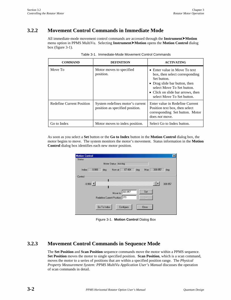
3.2.1 Status Information Status information consisting of the index position and the motor’s current and maximum position is displayed at the top of the Motion Control dialog box (see figure 3-1 on the following page), which you open by selecting Instrument Motion. If the motor is configured properly, the index position is identified as −10° and the maximum position is identified as 370°. The lines above and below the position control slide bar also roughly represent the motor’s current position.
The position reported as the motor’s current position and displayed in the Now at field in the Motion Control dialog box is determined by the number of pulses sent to the motor since its position was last defined; there is no direct feedback from which to obtain the exact sample position. To be certain the reported position matches the true sample orientation, you do the following : (a) set the position to −10°, (b) wait for the software to report it has reached −10°, and then (c) set the position to 370°. After the software reports it has reached 370°, the rotator should be at its upper physical limit (370°).
Section 3.2 Chapter 3 Controlling the Rotator Motor Rotator Motor Operation
3-2 PPMS Horizontal Rotator Option User’s Manual Quantum Design
3.2.2 Movement Control Commands in Immediate Mode All immediate-mode movement control commands are accessed through the Instrument Motion menu option in PPMS MultiVu. Selecting Instrument Motion opens the Motion Control dialog box (figure 3-1).
Table 3-1. Immediate-Mode Movement Control Commands
COMMAND DEFINITION ACTIVATING
Move To Motor moves to specified position.
• Enter value in Move To text box, then select corresponding Set button. • Drag slide bar button, then select Move To Set button. • Click on slide bar arrows, then select Move To Set button.
Redefine Current Position System redefines motor’s current position as specified position.
Enter value in Redefine Current Position text box, then select corresponding Set button. Motor does not move.
Go to Index Motor moves to index position. Select Go to Index button.
As soon as you select a Set button or the Go to Index button in the Motion Control dialog box, the motor begins to move. The system monitors the motor’s movement. Status information in the Motion Control dialog box identifies each new motor position.
Figure 3-1. Motion Control Dialog Box
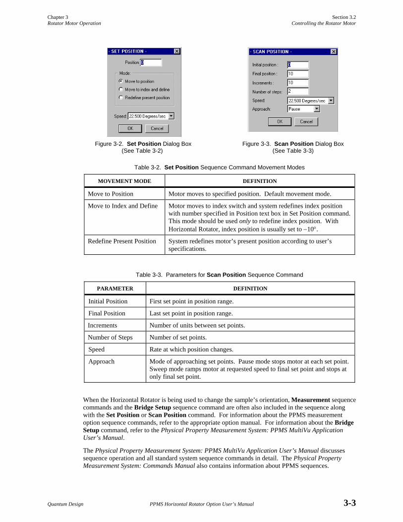
3.2.3 Movement Control Commands in Sequence Mode The Set Position and Scan Position sequence commands move the motor within a PPMS sequence. Set Position moves the motor to single specified position. Scan Position, which is a scan command, moves the motor to a series of positions that are within a specified position range. The Physical Property Measurement System: PPMS MultiVu Application User’s Manual discusses the operation of scan commands in detail.
Chapter 3 Section 3.2 Rotator Motor Operation Controlling the Rotator Motor
Quantum Design PPMS Horizontal Rotator Option User’s Manual 3-3
Figure 3-2. Set Position Dialog Box (See Table 3-2)
Figure 3-3. Scan Position Dialog Box (See Table 3-3)
Table 3-2. Set Position Sequence Command Movement Modes
MOVEMENT MODE DEFINITION
Move to Position Motor moves to specified position. Default movement mode.
Move to Index and Define Motor moves to index switch and system redefines index position with number specified in Position text box in Set Position command. This mode should be used only to redefine index position. With Horizontal Rotator, index position is usually set to −10°.
Redefine Present Position System redefines motor’s present position according to user’s specifications.
Table 3-3. Parameters for Scan Position Sequence Command
PARAMETER DEFINITION
Initial Position First set point in position range.
Final Position Last set point in position range.
Increments Number of units between set points.
Number of Steps Number of set points.
Speed Rate at which position changes.
Approach Mode of approaching set points. Pause mode stops motor at each set point. Sweep mode ramps motor at requested speed to final set point and stops at only final set point.
When the Horizontal Rotator is being used to change the sample’s orientation, Measurement sequence commands and the Bridge Setup sequence command are often also included in the sequence along with the Set Position or Scan Position command. For information about the PPMS measurement option sequence commands, refer to the appropriate option manual. For information about the Bridge Setup command, refer to the Physical Property Measurement System: PPMS MultiVu Application User’s Manual.
The Physical Property Measurement System: PPMS MultiVu Application User’s Manual discusses sequence operation and all standard system sequence commands in detail. The Physical Property Measurement System: Commands Manual also contains information about PPMS sequences.
Section 3.3 Chapter 3 Setting the Position Configuration Parameters Rotator Motor Operation
3-4 PPMS Horizontal Rotator Option User’s Manual Quantum Design
3.3 Setting the Position Configuration Parameters Note: The position configuration parameters are automatically set by the downloaded rotator configuration file and should never need to be modified unless the speed of the motor must be adjusted or the type of motor being used in the system is changed. Generally, the position configuration parameters are set once during system setup.
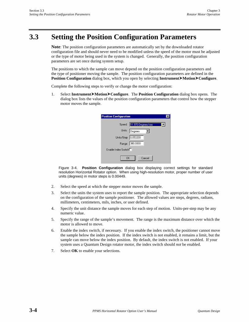
The positions to which the sample can move depend on the position configuration parameters and the type of positioner moving the sample. The position configuration parameters are defined in the Position Configuration dialog box, which you open by selecting Instrument Motion Configure.
Complete the following steps to verify or change the motor configuration:
1. Select Instrument Motion Configure. The Position Configuration dialog box opens. The dialog box lists the values of the position configuration parameters that control how the stepper motor moves the sample.
Figure 3-4. Position Configuration dialog box displaying correct settings for standard resolution Horizontal Rotator option. When using high-resolution motor, proper number of user units (degrees) in motor steps is 0.00449.
2. Select the speed at which the stepper motor moves the sample. 3. Select the units the system uses to report the sample position. The appropriate selection depends
on the configuration of the sample positioner. The allowed values are steps, degrees, radians, millimeters, centimeters, mils, inches, or user defined.
4. Specify the unit distance the sample moves for each step of motion. Units-per-step may be any numeric value.
5. Specify the range of the sample’s movement. The range is the maximum distance over which the motor is allowed to move.
6. Enable the index switch, if necessary. If you enable the index switch, the positioner cannot move the sample below the index position. If the index switch is not enabled, it remains a limit, but the sample can move below the index position. By default, the index switch is not enabled. If your system uses a Quantum Design rotator motor, the index switch should not be enabled.
7. Select OK to enable your selections.
Chapter 3 Section 3.4 Rotator Motor Operation Measurement Considerations
Quantum Design PPMS Horizontal Rotator Option User’s Manual 3-5
3.4 Measurement Considerations Most measurement considerations to take into account when designing experiments and writing sequences with the Horizontal Rotator option center around the issue of backlash and the tortional spring found on the rotator. The thermal characteristics and electrical limits of the hardware should also be kept in mind.
The Horizontal Rotator comprises a significant thermal load for the PPMS. The rotator thermometer closely monitors the temperature of the sample(s) on the rotator. However, introducing such a load into the PPMS sample chamber noticeably reduces the speed of the temperature control in the PPMS, especially at higher temperatures (See Section 1.3.1 about Current Leads). Sequences involving temperature changes may take longer than similar sequences run without a rotator installed in the PPMS.
The meshing of the rotator gears is also temperature dependent. Typical behavior is less than 2° of backlash at room temperature (due almost entirely to backlash in the motor), up to 8° of backlash at 150 K, and roughly 6° of backlash at 10 K. While the tortional spring on the rotator is effective at removing backlash at room temperature, its functionality reduces with temperature. Furthermore, if not used conscientiously, the spring can actually cause misleading rotator behavior if the rotator platform circuit board begins to alternately stick and slip during consecutive measurements with small angular changes.
To avoid backlash issues altogether, measurements should always be taken after approaching the sample orientation from the same direction. Since the spring can allow alternate sticking/slipping behavior while it is being unwound, measurements should generally be performed as the spring is being wound tighter. This occurs as the angular orientation is being decreased. To achieve the smoothest rotation and most reproducible results, measurements should always be taken on decreasing angles.
Even with taking such precautions, the correlation of rotator platform orientation to vernier dial reading varies with temperature, up to ±3°. To fully characterize your rotator at a designated temperature, you may wish to use a Hall sensor, which can be obtained from Quantum Design.
Quantum Design PPMS Horizontal Rotator Option User’s Manual A-1
A P P E N D I X A
PPMS Firmware Commands
A.1 Introduction This appendix contains the following information:
• Section A.2 displays the PPMS firmware command tree.
• Section A.3 discusses the firmware commands generally used with the Horizontal Rotator.
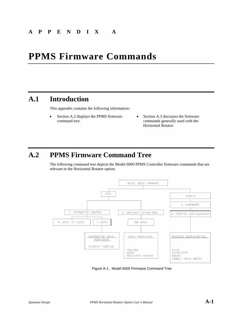
A.2 PPMS Firmware Command Tree The following command tree depicts the Model 6000 PPMS Controller firmware commands that are relevant to the Horizontal Rotator option.
Figure A-1. Model 6000 Firmware Command Tree
Section A.3 Appendix A Function of PPMS Firmware Commands PPMS Firmware Commands
A-2 PPMS Horizontal Rotator Option User’s Manual Quantum Design
A.3 Function of PPMS Firmware Commands
A.3.1 PPMS Firmware Setup Commands Configuration of the firmware for proper hardware motion control ensures that the PPMS is set up so that measurements may be made properly. Configuration files that are used for the Horizontal Rotator are written into nonvolatile RAM when downloaded to the Model 6000. Alternately, the position configuration can be set from the Model 6000 front panel, as described in the next section.
A.3.1.1 MODEL 6000 POSITION CONFIGURATION COMMANDS
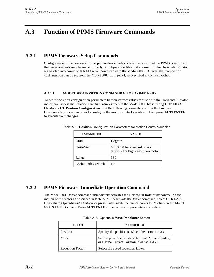
To set the position configuration parameters to their correct values for use with the Horizontal Rotator motor, you access the Position Configuration screen in the Model 6000 by selecting CONFIG 6. Hardware 3. Position Configuration. Set the following parameters within the Position Configuration screen in order to configure the motion control variables. Then press ALT+ENTER to execute your changes.
Table A-1. Position Configuration Parameters for Motion Control Variables
PARAMETER VALUE
Units Degrees
Units/Step 0.053200 for standard motor 0.00449 for high-resolution motor
Range 380
Enable Index Switch No
A.3.2 PPMS Firmware Immediate Operation Command The Model 6000 Move command immediately activates the Horizontal Rotator by controlling the motion of the motor as described in table A-2. To activate the Move command, select CTRL 3. Immediate Operations 03 Move or press Enter while the cursor points to Position on the Model 6000 STATUS screen. Press ALT+ENTER to execute any parameters you select.
Table A-2. Options in Move Positioner Screen
SELECT IN ORDER TO
Position Specify the position to which the motor moves.
Mode Set the positioner mode to Normal, Move to Index, or Define Current Position. See table A-3.
Reduction Factor Select the speed reduction factor.
Appendix A Section A.3 PPMS Firmware Commands Function of PPMS Firmware Commands
Quantum Design PPMS Horizontal Rotator Option User’s Manual A-3
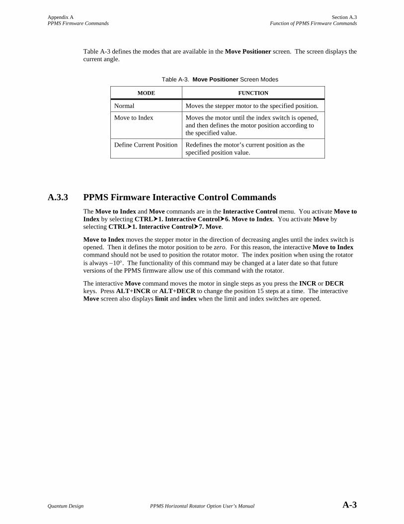
Table A-3 defines the modes that are available in the Move Positioner screen. The screen displays the current angle.
Table A-3. Move Positioner Screen Modes
MODE FUNCTION
Normal Moves the stepper motor to the specified position.
Move to Index Moves the motor until the index switch is opened, and then defines the motor position according to the specified value.
Define Current Position Redefines the motor’s current position as the specified position value.
A.3.3 PPMS Firmware Interactive Control Commands The Move to Index and Move commands are in the Interactive Control menu. You activate Move to Index by selecting CTRL 1. Interactive Control 6. Move to Index. You activate Move by selecting CTRL 1. Interactive Control 7. Move.
Move to Index moves the stepper motor in the direction of decreasing angles until the index switch is opened. Then it defines the motor position to be zero. For this reason, the interactive Move to Index command should not be used to position the rotator motor. The index position when using the rotator is always −10°. The functionality of this command may be changed at a later date so that future versions of the PPMS firmware allow use of this command with the rotator.
The interactive Move command moves the motor in single steps as you press the INCR or DECR keys. Press ALT+INCR or ALT+DECR to change the position 15 steps at a time. The interactive Move screen also displays limit and index when the limit and index switches are opened.
Quantum Design PPMS Horizontal Rotator Option User’s Manual B-1
A P P E N D I X B
Interconnection Tables
B.1 Introduction This appendix contains the following information:
• Section B.2 shows the standard inter-connections for the Horizontal Rotator.
• Section B.4 shows the interconnections for the motor.
• Section B.3 shows the interconnections for the ACT/Horizontal Rotator cable.
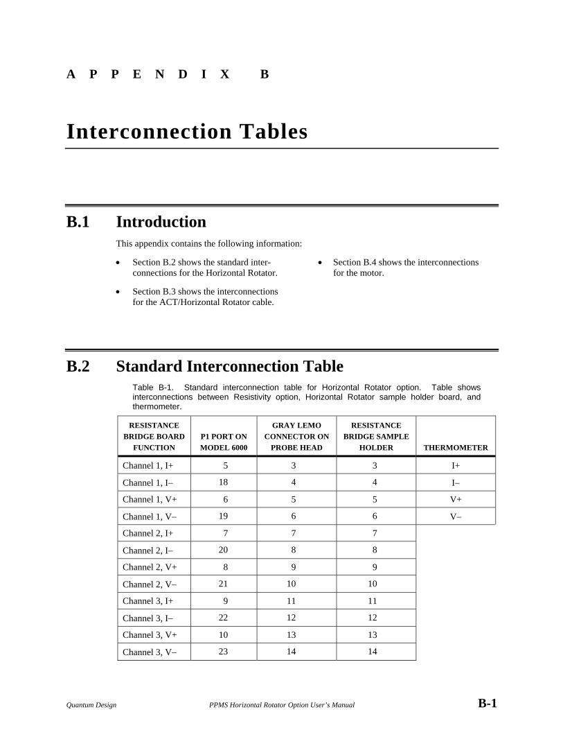
B.2 Standard Interconnection Table Table B-1. Standard interconnection table for Horizontal Rotator option. Table shows interconnections between Resistivity option, Horizontal Rotator sample holder board, and thermometer.
RESISTANCE BRIDGE BOARD
FUNCTION
P1 PORT ON MODEL 6000
GRAY LEMO CONNECTOR ON
PROBE HEAD
RESISTANCE BRIDGE SAMPLE
HOLDER
THERMOMETER
Channel 1, I+ 5 3 3 I+
Channel 1, I− 18 4 4 I−
Channel 1, V+ 6 5 5 V+
Channel 1, V− 19 6 6 V−
Channel 2, I+ 7 7 7
Channel 2, I− 20 8 8
Channel 2, V+ 8 9 9
Channel 2, V− 21 10 10
Channel 3, I+ 9 11 11
Channel 3, I− 22 12 12
Channel 3, V+ 10 13 13
Channel 3, V− 23 14 14
Section B.3 Appendix B Interconnection Tables for the ACT/Horizontal Rotator Probe Cable Interconnection Tables
B-2 PPMS Horizontal Rotator Option User’s Manual Quantum Design
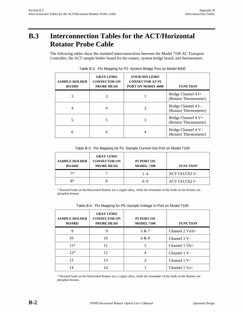
B.3 Interconnection Tables for the ACT/Horizontal Rotator Probe Cable The following tables show the standard interconnections between the Model 7100 AC Transport Controller, the ACT sample holder board for the rotator, system bridge board, and thermometer.
Table B-2. Pin Mapping for P2−System Bridge Port on Model 6000
SAMPLE HOLDER
BOARD
GRAY LEMO CONNECTOR ON
PROBE HEAD
FOUR-PIN LEMO CONNECTOR AT P2
PORT ON MODEL 6000
FUNCTION
3 3 1 Bridge Channel 4 I+ (Rotator Thermometer)
4 4 2 Bridge Channel 4 I− (Rotator Thermometer)
5 5 3 Bridge Channel 4 V+ (Rotator Thermometer)
6 6 4 Bridge Channel 4 V− (Rotator Thermometer)
Table B-3. Pin Mapping for P1−Sample Current Out Port on Model 7100
SAMPLE HOLDER
BOARD
GRAY LEMO CONNECTOR ON
PROBE HEAD
P1 PORT ON MODEL 7100
FUNCTION
7* 7 1−4 ACT Ch1/Ch2 I+
8* 8 6−9 ACT Ch1/Ch2 I−
* Denoted leads on the Horizontal Rotator are a copper alloy, while the remainder of the leads on the Rotator are phosphor-bronze.
Table B-4. Pin Mapping for P5−Sample Voltage In Port on Model 7100
SAMPLE HOLDER
BOARD
GRAY LEMO CONNECTOR ON
PROBE HEAD
P5 PORT ON MODEL 7100
FUNCTION
9 9 5 & 7 Channel 2 Va/b+
10 10 6 & 8 Channel 2 V−
11* 11 3 Channel 1 Vb+
12* 12 4 Channel 1 V−
13 13 2 Channel 1 V−
14 14 1 Channel 1 Va+
* Denoted leads on the Horizontal Rotator are a copper alloy, while the remainder of the leads on the Rotator are phosphor-bronze.
Appendix B Section B.4 Interconnection Tables Motor Interconnection Table
Quantum Design PPMS Horizontal Rotator Option User’s Manual B-3
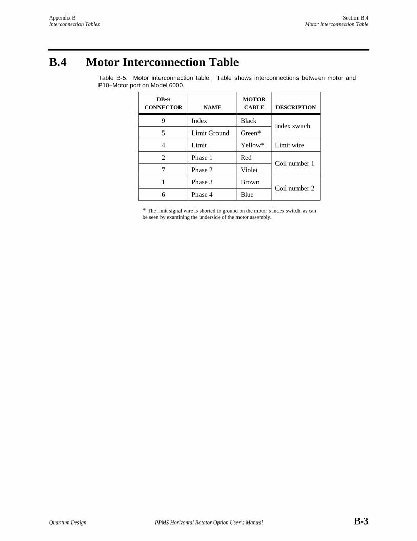
B.4 Motor Interconnection Table Table B-5. Motor interconnection table. Table shows interconnections between motor and P10−Motor port on Model 6000.
DB-9 CONNECTOR
NAME
MOTOR CABLE
DESCRIPTION
9 Index Black
5 Limit Ground Green* Index switch
4 Limit Yellow* Limit wire
2 Phase 1 Red
7 Phase 2 Violet Coil number 1
1 Phase 3 Brown
6 Phase 4 Blue Coil number 2
* The limit signal wire is shorted to ground on the motor’s index switch, as can be seen by examining the underside of the motor assembly.
Quantum Design PPMS Horizontal Rotator Option User’s Manual References-1
References
Quantum Design. 2000. Physical Property Measurement System: AC Transport Option User’s Manual.
⎯⎯⎯. 1995. Physical Property Measurement System: Commands Manual.
⎯⎯⎯. 1996. Physical Property Measurement System: Firmware Manual.
⎯⎯⎯. 2000. Physical Property Measurement System: Hardware Manual.
⎯⎯⎯. 2000. Physical Property Measurement System: PPMS MultiVu Application User’s Manual.
⎯⎯⎯. 1999. Physical Property Measurement System: Resistivity Option User’s Manual.
Quantum Design PPMS Horizontal Rotator Option User’s Manual Index-1
Index
ACT/Horizontal Rotator probe cable connecting, 2-5 interconnection tables, B-2 rotator configuration file used with, 2-7 ACT option cable. See ACT/Horizontal Rotator probe cable kit for operation with Horizontal Rotator, 1-3 system bridge board reading rotator thermometer, 1-5, 2-7 AC Transport sample holder board. See also Sample holder board interconnection tables, B-2 part number, 1-3 Backlash, 3-5 Calibration, of sample position, 2-8 Configuration files. See Rotator configuration files Configuration parameters. See Position configuration parameters Electrical connections diagram, 1-2 Firmware commands function, A-2−A-3 tree displaying, A-1 Hardware effect on measurements, 3-5 installing, 2-5−2-6 list of, 1-1. See also Horizontal Rotator probe; Horizontal Rotator support plate; Sample holder board removing, 2-9 High-resolution rotator motor. See Rotator motor Horizontal Rotator option accessories, part numbers for, 1-3 configuration files. See Rotator configuration files connection diagram, 1-2 hardware, list of, 1-1. See also Horizontal Rotator probe; Horizontal Rotator support plate; Sample holder board installing, 2-1, 2-5−2-6 interconnection table, B-1 measurements with. See Measurements operating modes, 1-2. See also Rotator motor: Moving overview, 1-1 PPMS option compatibility, 1-2. See also ACT option reducing PPMS temperature control speed, 3-5 removing, 2-9 rotation range, 1-1
Horizontal Rotator probe ice on, 1-5 illustration, 1-4 installing, 2-5−2-6 maintenance, 1-3, 1-5 overview, 1-4 part number, 1-1 proper handling, 1-4, 1-5 removing, 2-9 storing vertically, 1-5, 2-9 Horizontal Rotator support plate illustration, 2-6 installing, 2-5−2-6 maintenance, 1-3 part number, 1-1 removing, 2-9 Index catch disk changing sample holder board orientation, 1-6 in illustration of Horizontal Rotator probe, 1-4 Index position moving motor to, 3-2 proper location, 3-1 redefining, 3-3 Index switch, enabling, 3-4 Installation hardware, 2-5−2-6 overview, 2-1 Interconnection table ACT/Horizontal Rotator probe cable, B-2 motor, B-3 standard, B-1 Maintenance, 1-3 Measurements considerations, 3-5 preparing for, 2-1 Model 6000 position configuration commands, A-2 Motor cable connecting, 2-6 function, 1-2 Movement control commands. See also Position configuration parameters in immediate mode, 3-1, 3-2 in sequence mode, 3-1, 3-2−3-3 O-rings illustration on Horizontal Rotator probe, 1-4 on Horizontal Rotator support plate, 2-6 maintenance, 1-3

Index
Index-2 PPMS Horizontal Rotator Option User’s Manual Quantum Design
P-10 port connection port for motor cable, 1-2, 2-6 interconnection table, B-3 location on Model 6000, illustration of, 1-2 Part numbers, list of, 1-1, 1-3 Pause mode, 3-3 Position calibration, 2-8 Position configuration parameters, changing, 3-4. See also Model 6000 position configuration commands Resistance bridge sample holder board. See also Sample holder board contact pad functions, 2-3 current leads connected to, 1-5 part number, 1-1 wiring samples to, 2-2 Resistivity option, 1-2 Romcfg32 utility, 2-7 Rotator configuration files downloading, 2-7 setting position configuration parameters, 3-4 Rotator motor connection diagram, 1-2 interconnection table, B-3 moving. See also Firmware commands in immediate mode, 3-1, 3-2 in sequence mode, 3-1, 3-2−3-3 position configuration parameters, 3-4 specifications, 1-1, 3-4 status, 3-1, 3-2 Rotator platform circuit board attaching sample holder board to, 2-3−2-5 current leads, 1-5 illustration close-up view, 2-4 location on Horizontal Rotator probe, 1-4 Rotator support tool illustration, 2-3 part number, 1-1 stabilizing rotator transfer case, 2-4 Rotator thermometer bridge board reading, 1-5, 2-7 calibration defined in rotator configuration file, 2-7 contact pads, 1-5, 2-2 disconnecting, 2-2 functioning as user thermometer, 1-5, 2-7 interconnection table, B-1 maintenance, 1-3, 1-5 Rotator transfer case illustration close-up view, 2-4 location on Horizontal Rotator probe, 1-4 orienting on rotator support tool, 2-4 proper handling, 1-4
Sample installing. See Horizontal Rotator probe: Installing measuring. See Measurements mounting, 2-2 moving. See Movement control commands position calibration, 2-8 size, 2-2 Sample holder board attaching to rotator platform, 2-3−2-5 changing orientation of, 1-6 illustration, 2-4 installing in sample chamber. See Horizontal Rotator probe: Installing mounting sample on, 2-2 part number, 1-3 removing from rotator platform, 2-5 Sample removal tool illustration, 2-3 part number, 1-1 using, 2-4, 2-5 Scan Position sequence command moving motor to multiple positions, 3-2 parameters, 3-3 Sequence operation, 3-3, 3-5 Set Position sequence command function, 3-2 movement modes, 3-3 Software, using, 3-1. See also Movement control commands Standard rotator motor. See Rotator motor Status information, 3-1, 3-2 Sweep mode, 3-3 System bridge board interconnection tables, B-2 reading rotator thermometer when ACT option is activated, 1-5, 2-7 Temperature control, affected by Horizontal Rotator, 3-5 User bridge board keeping normal channel settings, 1-5 reading rotator thermometer, 1-5, 2-7 wiring samples to, 2-2 User bridge cable, 2-5, 2-7 UserTemp turning off, 2-9 turning on, 2-7 Vernier dial correlation to rotator platform orientation, 3-5 in illustration of Horizontal Rotator probe, 1-4 turning, 1-2


