
Physically Based Rendering
• Rendering that accurately reproduces the physical behavior of light– Laws of physics that represent the behavior of light
(electromagnetic waves)• Geometrical Optics• Wave Optics
– Wave Equation» Maxwell’s equations
– Scattering Equation» Compton scattering» Rayleigh scattering» Mie scattering» Raman scattering» Etc…
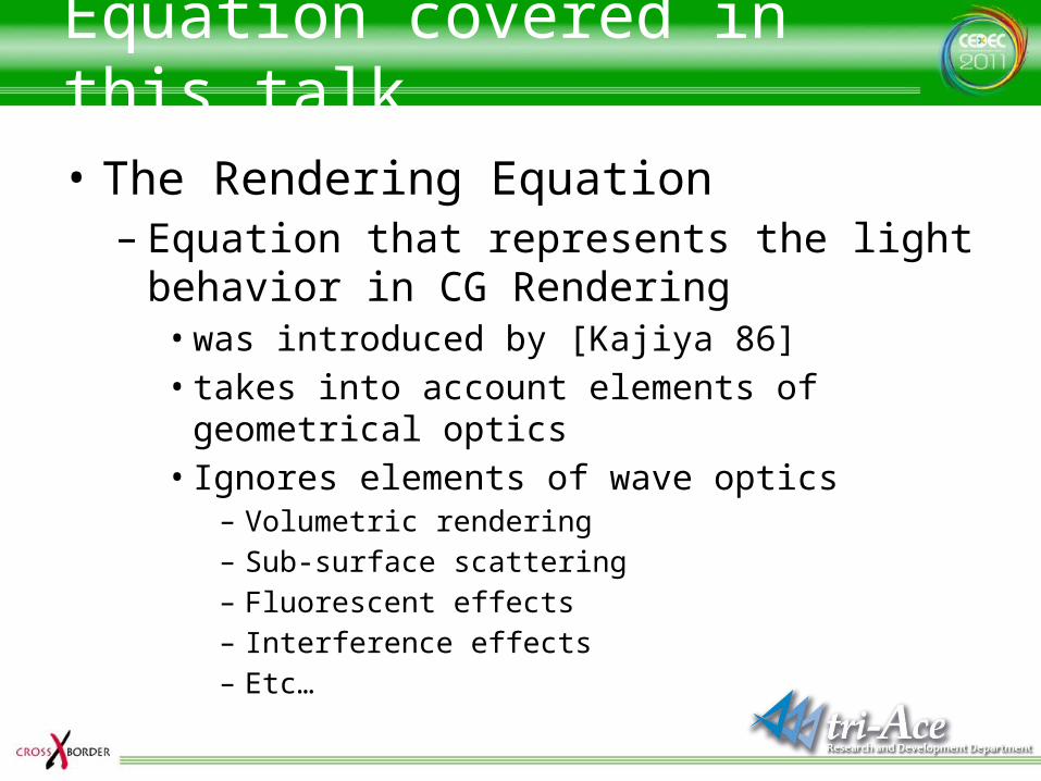
Equation covered in this talk
• The Rendering Equation– Equation that represents the light behavior in
CG Rendering• was introduced by [Kajiya 86]• takes into account elements of geometrical optics• Ignores elements of wave optics
– Volumetric rendering– Sub-surface scattering– Fluorescent effects– Interference effects– Etc…
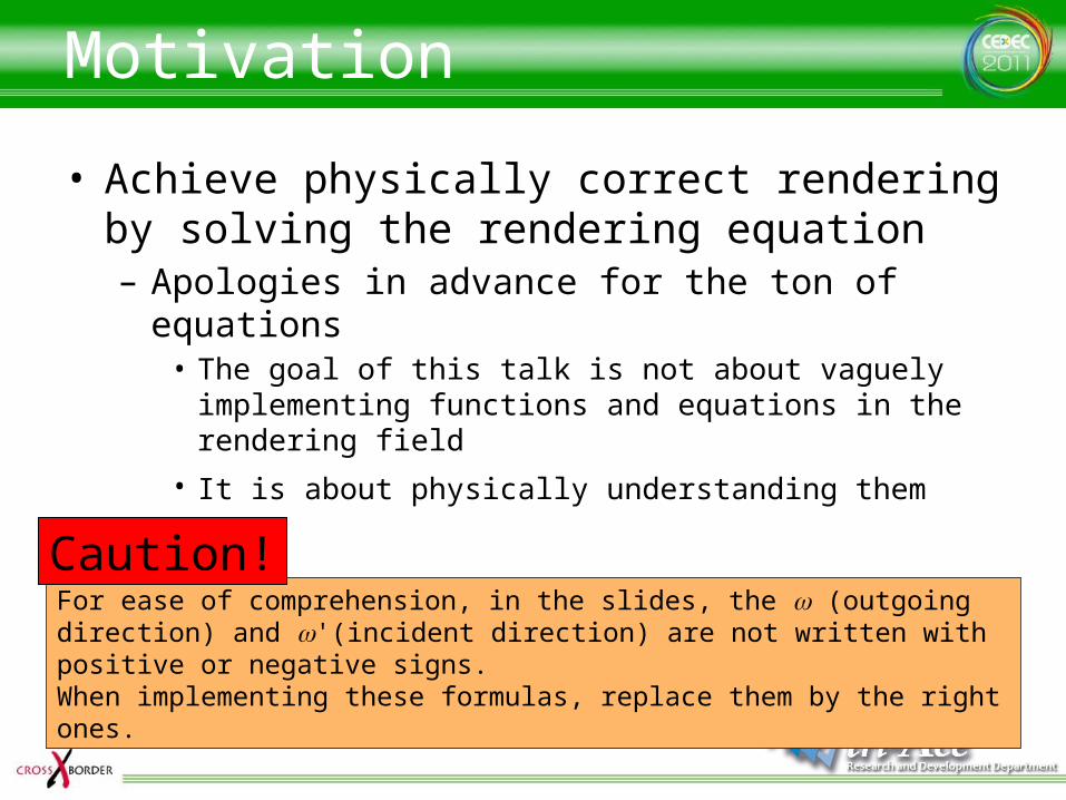
Motivation
• Achieve physically correct rendering by solving the rendering equation– Apologies in advance for the ton of equations
• The goal of this talk is not about vaguely implementing functions and equations in the rendering field
• It is about physically understanding them
For ease of comprehension, in the slides, the w (outgoing direction) and w'(incident direction) are not written with positive or negative signs.When implementing these formulas, replace them by the right ones.
Caution!
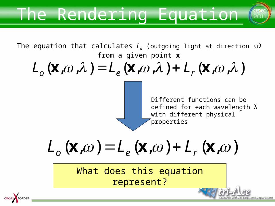
The Rendering Equation
),,(),,(),,( xxx reo LLL
The equation that calculates Lo (outgoing light at direction )w from a given point x
Different functions can be defined for each wavelength λ with different physical properties
),(),(),( xxx reo LLL What does this equation represent?
Radiance?
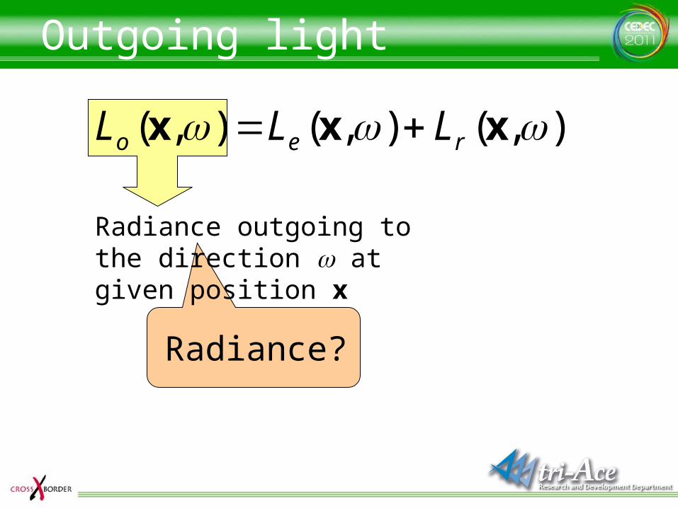
Outgoing light
Radiance outgoing to the direction w at given position x
),(),(),( xxx reo LLL
Radiance
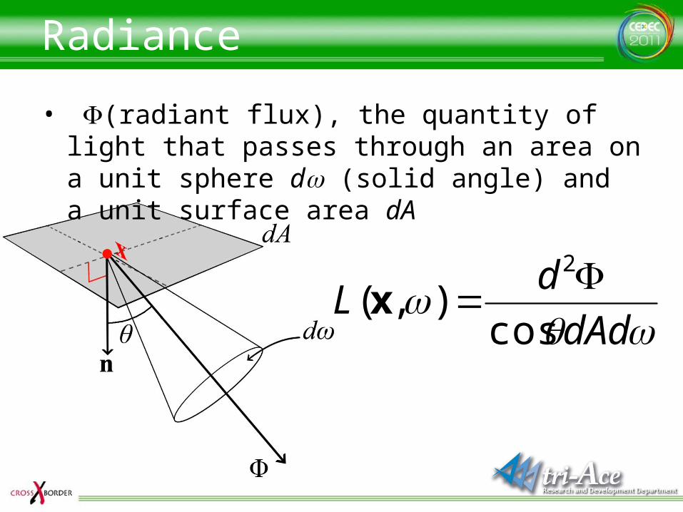
• F(radiant flux), the quantity of light that passes through an area on a unit sphere dw (solid angle) and a unit surface area dA
dAd
dL
cos),(
2x
Irradiance
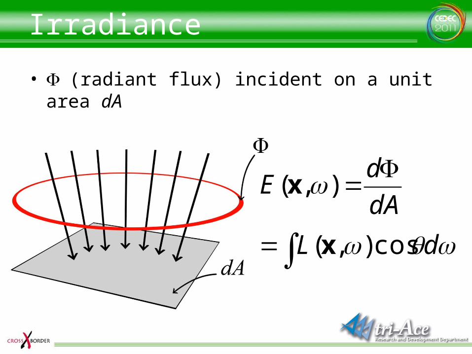
• F (radiant flux) incident on a unit area dA
dL
dA
dE
cos),(
),(
x
x
Radiant flux
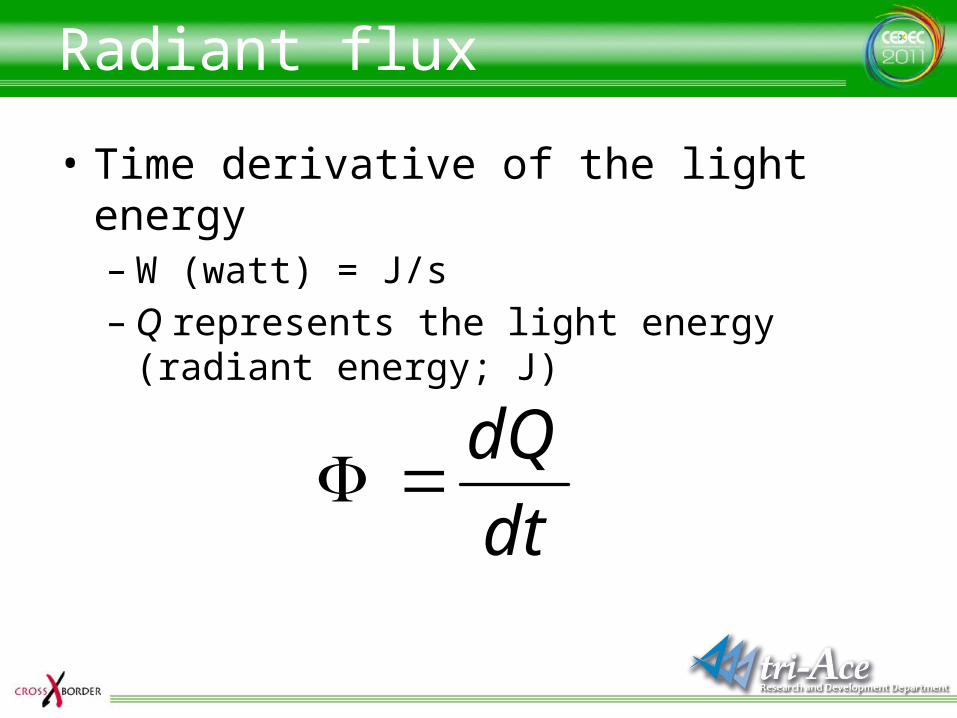
• Time derivative of the light energy– W (watt) = J/s– Q represents the light energy (radiant energy; J)
dt
dQ
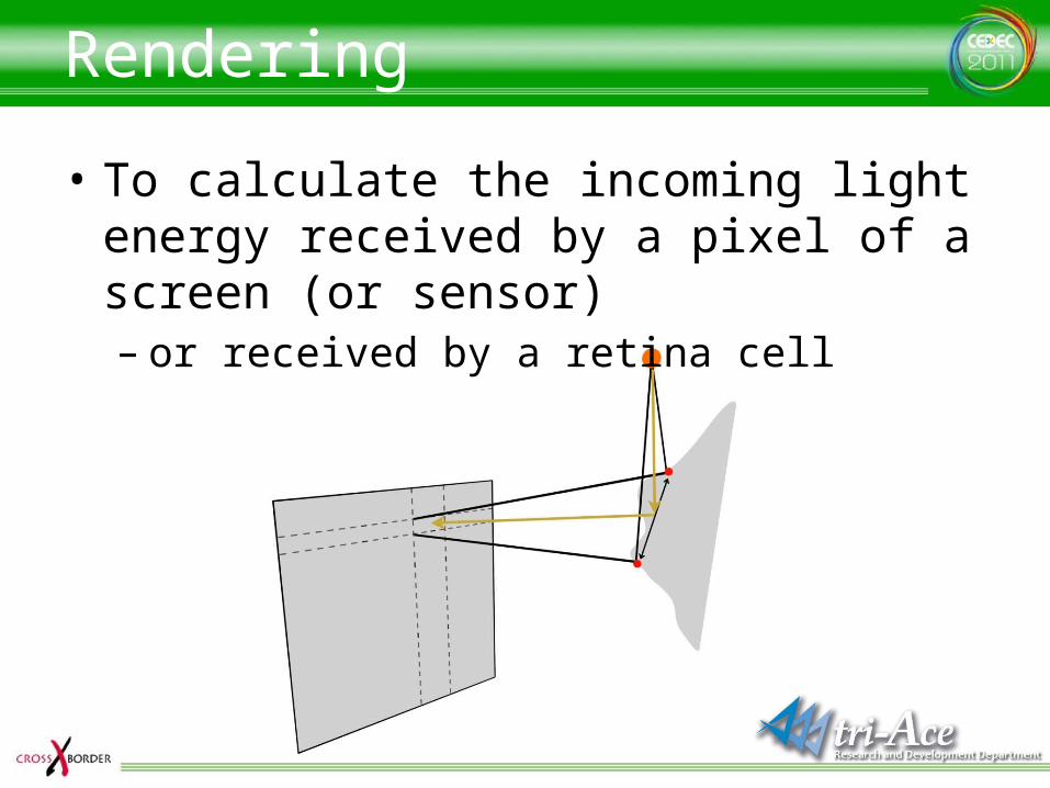
Rendering
• To calculate the incoming light energy received by a pixel of a screen (or sensor) – or received by a retina cell
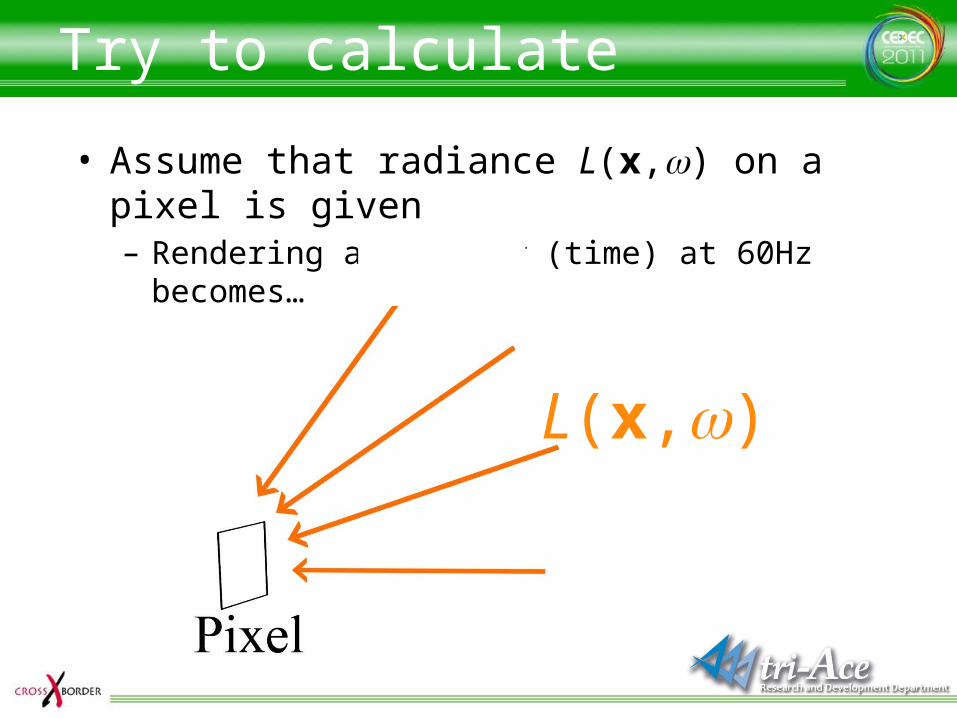
• Assume that radiance L(x,w) on a pixel is given– Rendering at frame t (time) at 60Hz becomes…
Try to calculate
L(x,w)
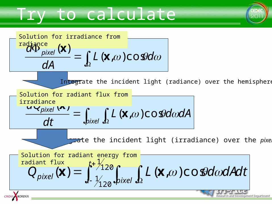
Solution for radiant energy from radiant flux
Solution for irradiance from radiance
Try to calculate
dLdA
d pixel cos),()(
xx
120
1
1201
cos),()(t
t pixelpixel dtdAdLQ xx
pixel
pixel dAdLdt
dQ cos),(
)(x
xSolution for radiant flux from irradiance
Integrate the incident light (irradiance) over the pixel domain
Integrate the incident light (radiance) over the hemisphere

Aperture
• Since the result is the sum of incident light from entire hemisphere, the image gets blurred– Introduce “aperture” as a solution
),( xapertureV 1 (where direction w is inside the aperture at x)
0 (where direction w is outside the aperture at x)
frame pixel aperturepixel dtdAdVLQ cos),(),()( xxx
Substitute
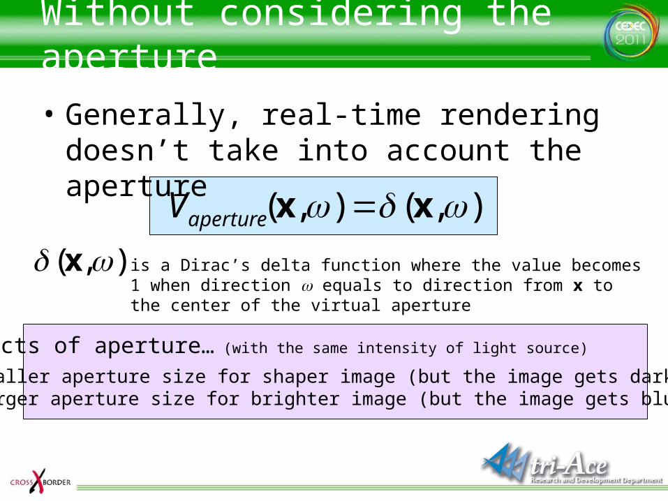
Without considering the aperture
• Generally, real-time rendering doesn’t take into account the aperture
),(),( xx apertureV
),( x is a Dirac’s delta function where the value becomes 1 when direction w equals to direction from x to the center of the virtual aperture
Effects of aperture… (with the same intensity of light source)
• Smaller aperture size for shaper image (but the image gets darker)• Larger aperture size for brighter image (but the image gets blurrier)
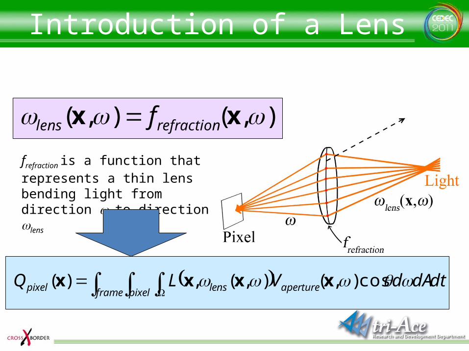
Introduction of a Lens
),(),( xx refractionlens f
frefraction is a function that represents a thin lens bending light from direction w to direction wlens
frame pixel aperturelenspixel dtdAdVLQ cos),(),(,)( xxxx
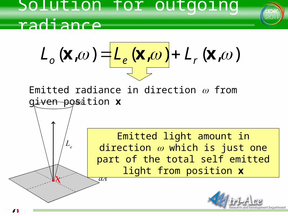
Solution for outgoing radiance
Emitted radiance in direction w from given position x
),(),(),( xxx reo LLL
Emitted light amount in direction w which is just one part of the total self emitted light
from position x
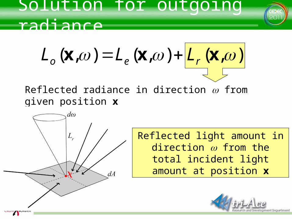
Solution for outgoing radiance
Reflected radiance in direction w from given position x
),(),(),( xxx reo LLL
Reflected light amount in direction w from the total incident light
amount at position x
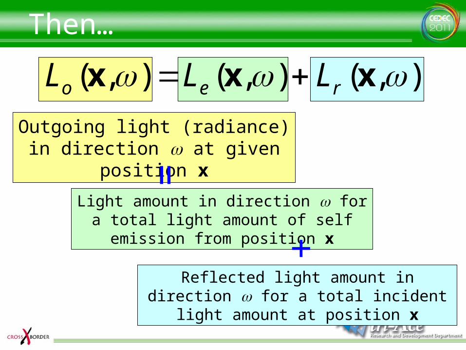
Then…
),(),(),( xxx reo LLL Outgoing light (radiance) in
direction w at given position x
Light amount in direction w for a total light amount of self emission from position x
Reflected light amount in direction w for a total incident light amount at position x=
+
Calculate Le (Self emission)
• As you like– Use an arbitrary function
• Texture?• Animation curve?• Illumination model?
– It represents a light source
Solution for Lr(reflection)
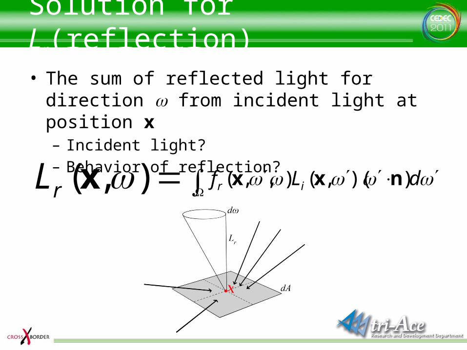
• The sum of reflected light for direction w from incident light at position x – Incident light?– Behavior of reflection?
),( xrL dLf ir ))(,(),,( nxx
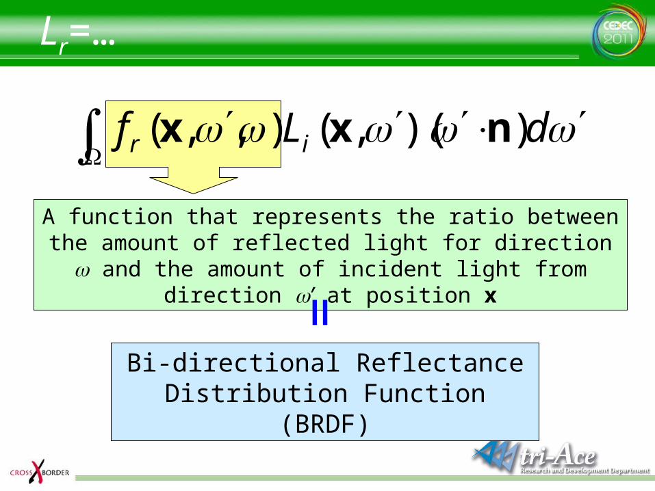
Lr=…
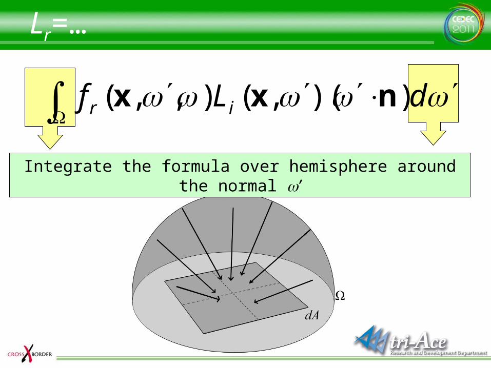
dLf ir ))(,(),,( nxx
Integrate the formula over hemisphere around the normal w’
Lr=…
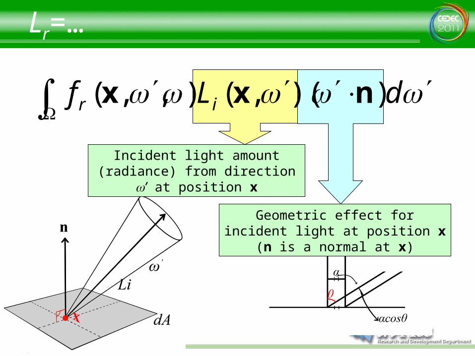
dLf ir ))(,(),,( nxx
Incident light amount (radiance) from direction w’ at position x
Geometric effect for incident light at position x (n is a normal at x)
Lr=…
dLf ir ))(,(),,( nxx
A function that represents the ratio between the amount of reflected light for direction w and the amount of incident
light from direction w’ at position x=Bi-directional Reflectance
Distribution Function (BRDF)
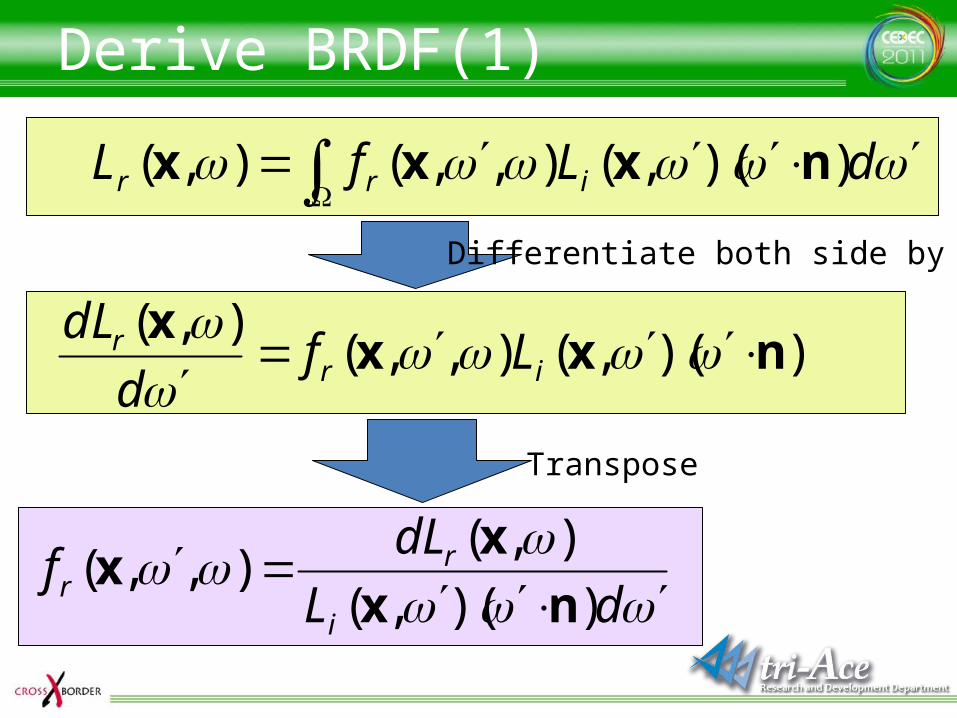
Derive BRDF(1)
dLfL irr ))(,(),,(),( nxxx
))(,(),,(),(
nxxx
irr Lfd
dL
dL
dLf
i
rr ))(,(
),(),,(
nx
xx
Differentiate both side by w’
Transpose
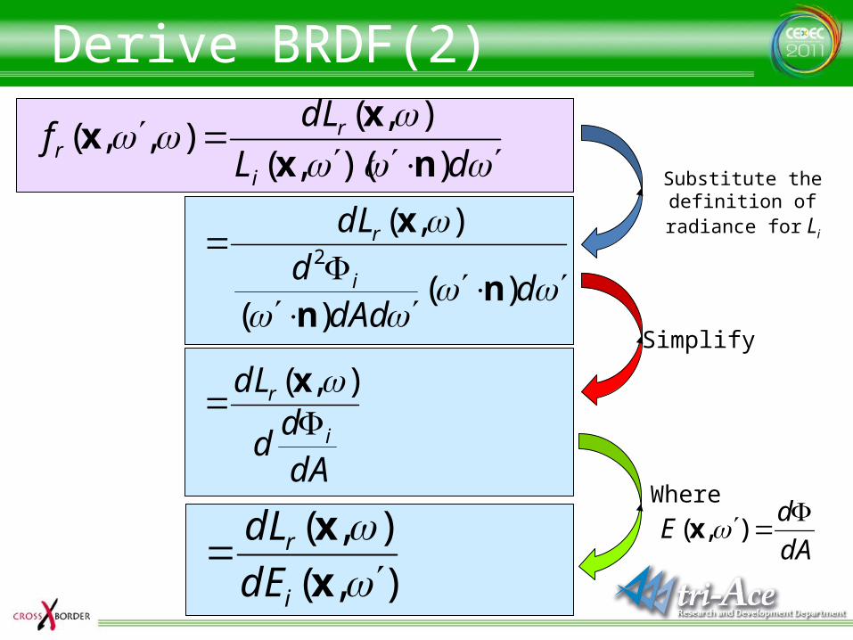
Derive BRDF(2)
dL
dLf
i
rr ))(,(
),(),,(
nx
xx
ddAd
ddL
i
r
)()(
),(2
nn
x
),(
),(
x
x
i
r
dE
dL
dAd
d
dL
i
r
),( x
Substitute the definition of radiance for Li
Simplify
dA
dE
),( x
Where
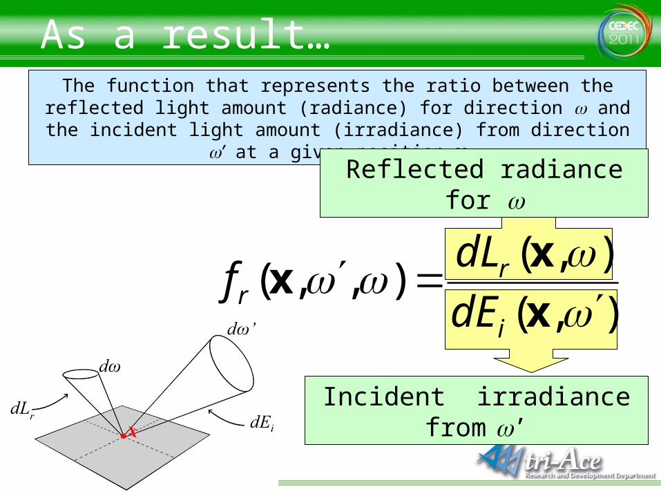
As a result…The function that represents the ratio between the reflected light amount (radiance) for direction w and the incident light amount (irradiance) from
direction w’ at a given position x
Reflected radiance for w
Incident irradiance from w’
),(
),(),,(
x
xx
i
rr dE
dLf
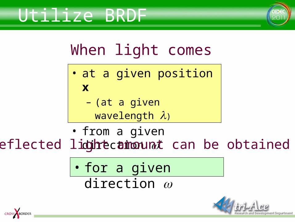
Utilize BRDF
• at a given position x– (at a given wavelength l)
• from a given direction w’
When light comes
• for a given direction w
Reflected light amount can be obtained
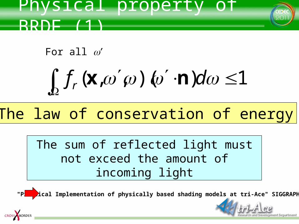
Physical property of BRDF (1)
1))(,,( dfr nx
For all w’
The law of conservation of energy
The sum of reflected light must not exceed the amount of incoming light
"Practical Implementation of physically based shading models at tri-Ace" SIGGRAPH 2010
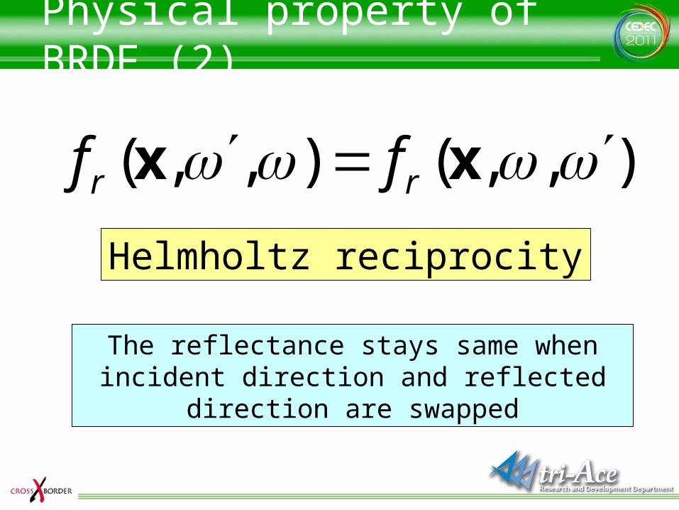
Physical property of BRDF (2)
Helmholtz reciprocity
The reflectance stays same when incident direction and reflected direction are swapped
),,(),,( xx rr ff
Swap L and E
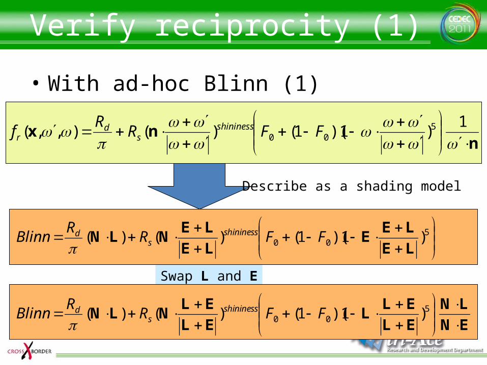
Verify reciprocity (1)
• With ad-hoc Blinn (1)
nnx
1
)1)(1()(),,( 500 FFR
Rf shininess
sd
r
500 )1)(1()()(
LE
LEE
LE
LENLN FFR
RBlinn shininess
sd
Describe as a shading model
EN
LN
EL
ELL
EL
ELNLN
500 )1)(1()()( FFR
RBlinn shininess
sd
Swap L and E
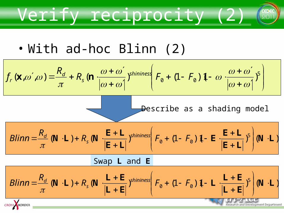
Verify reciprocity (2)
• With ad-hoc Blinn (2)
500 )1)(1()(),,(
FFR
Rf shininess
sd
r nx
)()1)(1()()( 500 LN
LE
LEE
LE
LENLN
FFRR
Blinn shininesss
d
)()1)(1()()( 500 LN
EL
ELL
EL
ELNLN
FFRR
Blinn shininesss
d
Describe as a shading model
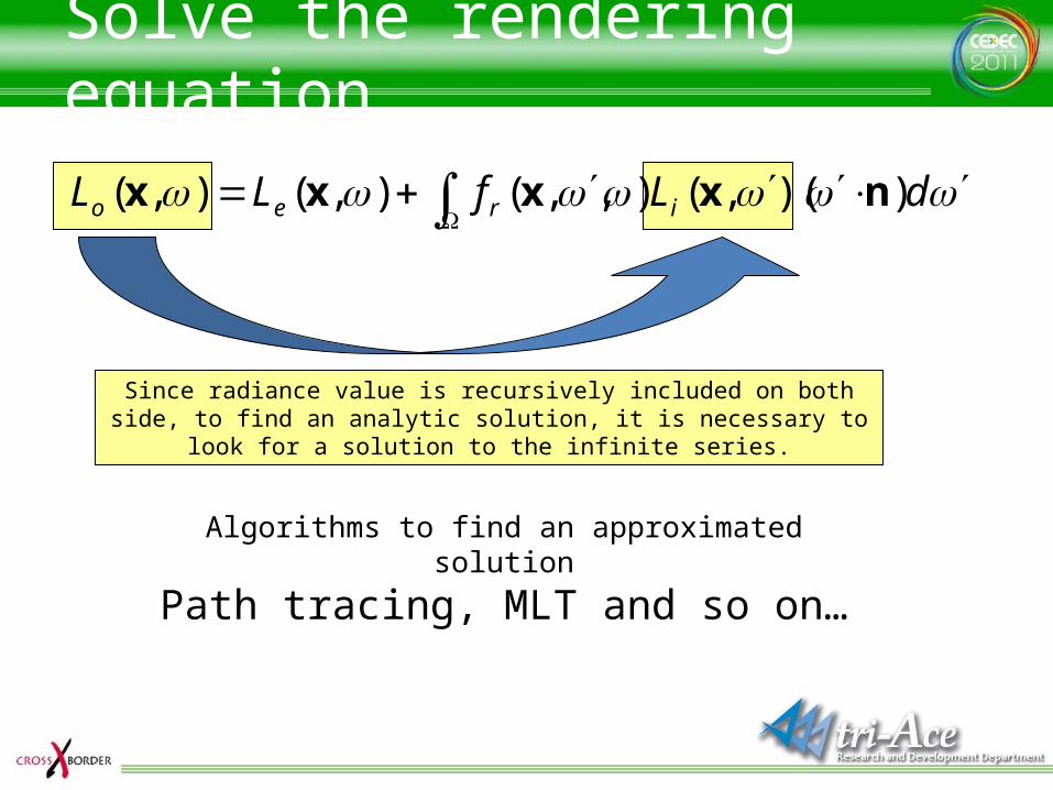
Solve the rendering equation
dLfLL ireo ))(,(),,(),(),( nxxxx
Since radiance value is recursively included on both side, to find an analytic solution, it is necessary to look for a solution to the infinite series.
Algorithms to find an approximated solution
Path tracing, MLT and so on…
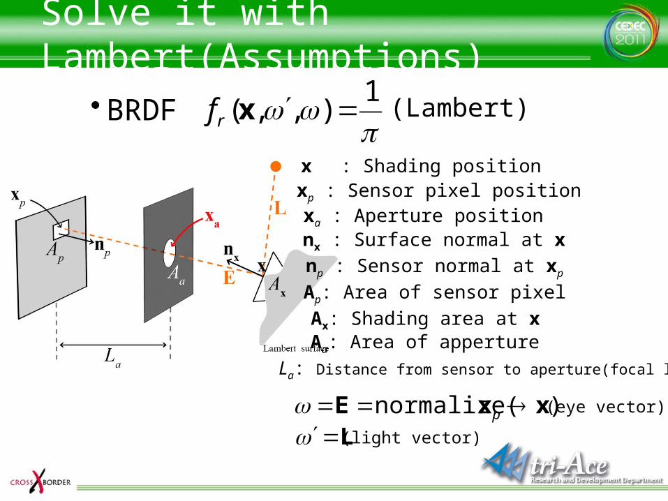
Solve it with Lambert(Assumptions)
•BRDF
1),,( xrf
)normalize( xxE p
(Lambert)
L
x : Shading positionxp : Sensor pixel position
nx : Surface normal at x
np : Sensor normal at xp
Ap: Area of sensor pixel
Ax: Shading area at x
(eye vector)
(light vector)
La: Distance from sensor to aperture(focal length)
Aa: Area of apperture
xa : Aperture position
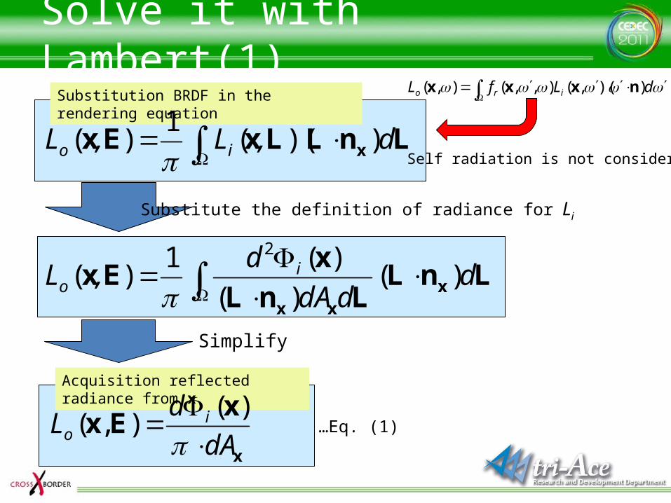
Solve it with Lambert(1)Substitution BRDF in the rendering equation dLfL iro ))(,(),,(),( nxxx
Self radiation is not considered
Substitute the definition of radiance for Li
Acquisition reflected radiance from x
x
xEx
dA
dL i
o
)(),(
Simplify
…Eq. (1)
LnLLxEx x d,L,L io ))((1
)(
LnLLnL
xEx x
xx
dddA
d,L i
o )()(
)(1)(
2
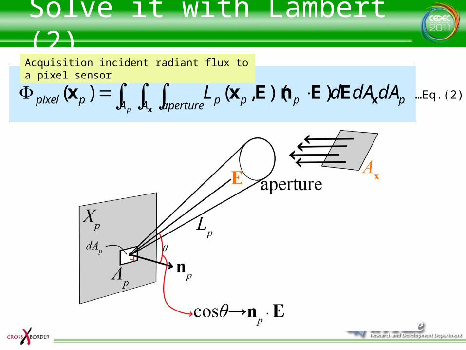
Solve it with Lambert (2)Acquisition incident radiant flux to a pixel sensor
…Eq.(2) pA A aperture ppppppixel dAdAdL
xxEEnExx ))(,()(
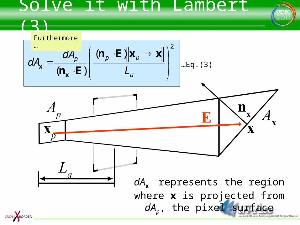
Solve it with Lambert (3)
2)(
)(
a
ppp
L
dAdA
xxEn
Enxx
Furthermore…
dAx represents the region where x is projected from dAp, the pixel surface
…Eq.(3)
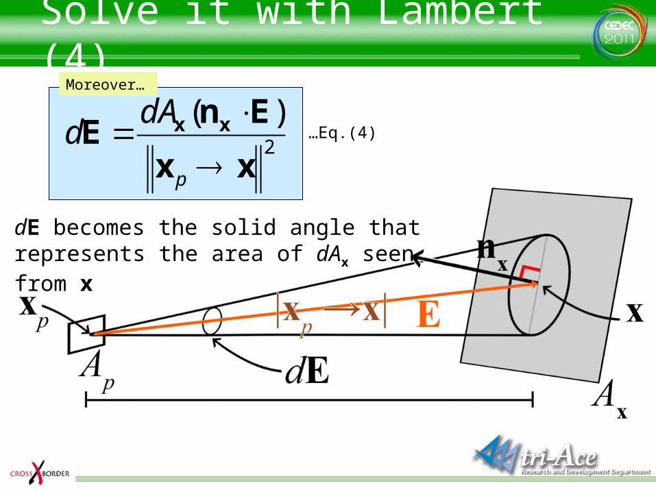
Solve it with Lambert (4)Moreover…
dE becomes the solid angle that represents the area of dAx seen from x
2
)(
xx
EnE xx
p
dAd …Eq.(4)
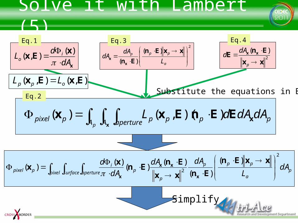
Solve it with Lambert (5)
Eq.2
pixel surface aperture p
a
ppp
p
pi
ppixel dAL
dAdA
dA
d2
2
)(
)(
)()(
)()(
xxEn
Enxx
EnEn
xx
x
xx
x
Eq.1
x
xEx
dA
dL i
o
)(),(
Eq.32
)(
)(
a
ppp
L
dAdA
xxEn
Enxx
Eq.4
2
)(
xx
EnE xx
p
dAd
Substitute the equations in Eq.2
Simplify
pA A aperture ppppppixel dAdAdL
xxEEnExx ))(,()(
),(),( ExEx opp LL
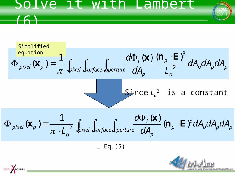
Solve it with Lambert (6)
Simplified equation
pixel surface aperture ppp
a
p
p
ippixel dAdAdA
LdA
d2
3)()(1)(
Enxx
Since La2 is a constant
pixel surface aperture ppppp
i
a
ppixel dAdAdAdA
d
L3
2 )()(1
)( Enx
x
… Eq.(5)
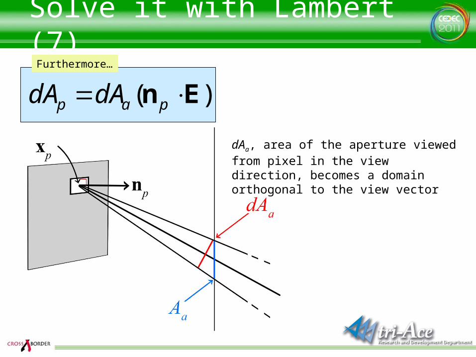
Solve it with Lambert (7)Furthermore…
)( En pap dAdA
dAa, area of the aperture viewed from pixel in the view direction, becomes a domain orthogonal to the view vector
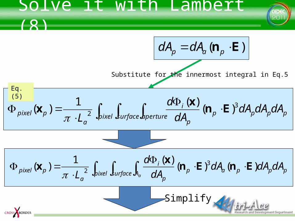
Solve it with Lambert (8)
)( En pap dAdA
pixel surface aperture ppppp
i
a
ppixel dAdAdAdA
d
L3
2 )()(1
)( Enx
x
Eq.(5)
Substitute for the innermost integral in Eq.5
ppppixel surface A app
i
a
ppixel dAdAdAdA
d
L a
)()()(1
)( 32 EnEn
xx
Simplify
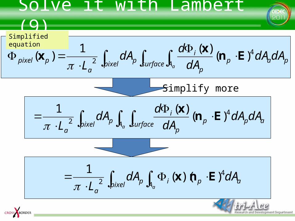
Solve it with Lambert (9)
ppixel surface A app
ip
a
ppixel dAdAdA
ddA
L a
42 )(
)(1)( En
xx
apixel A surface ppp
ip
a
dAdAdA
ddA
L a
42 )(
)(1En
x
apixel A pip
a
dAdAL a
4
2 ))((1
Enx
Simplified equation
Simplify more
Solve it with Lambert (10)
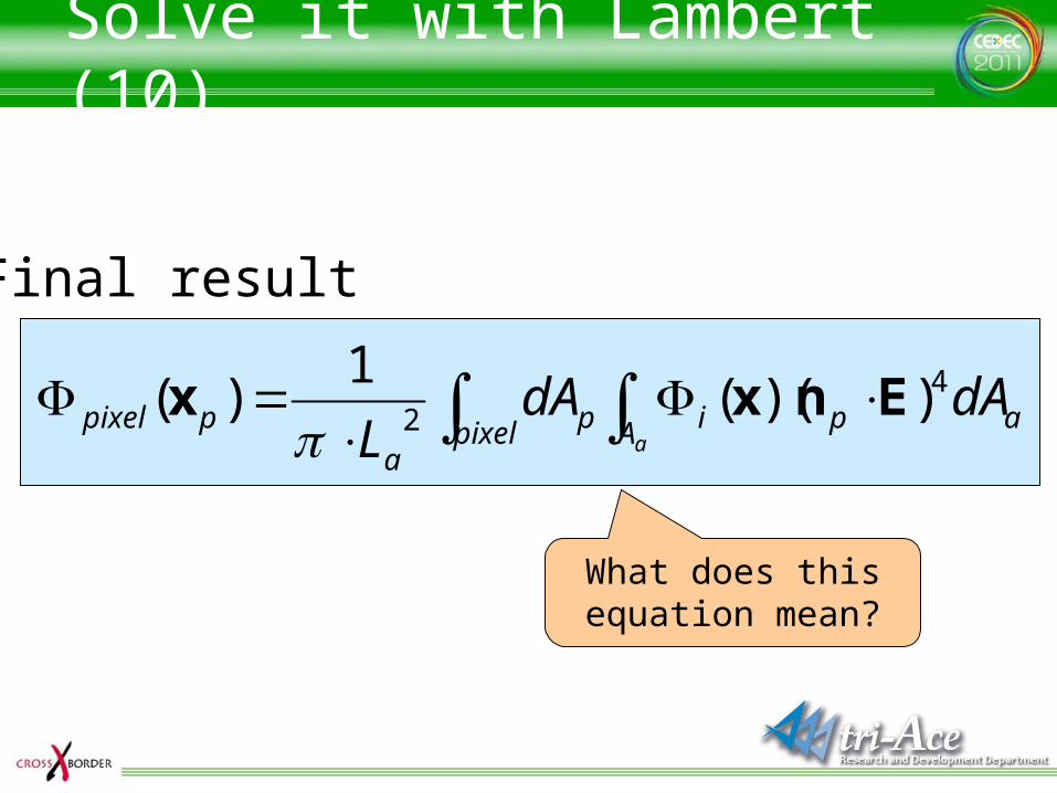
Final result
What does this equation mean?
pixel A apip
a
ppixela
dAdAL
42 ))((
1)( Enxx
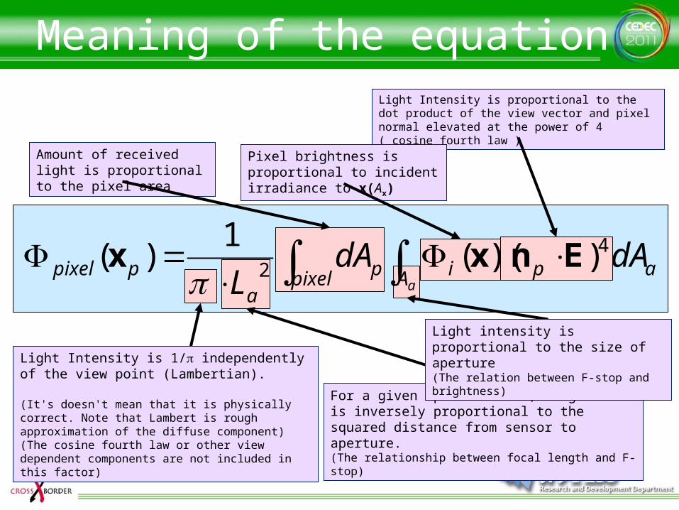
Meaning of the equationLight Intensity is proportional to the dot product of the view vector and pixel normal elevated at the power of 4 ( cosine fourth law )
For a given aperture size, brightness is inversely proportional to the squared distance from sensor to aperture.(The relationship between focal length and F-stop)
Light intensity is proportional to the size of aperture(The relation between F-stop and brightness)
Amount of received light is proportional to the pixel area
Light Intensity is 1/p independently of the view point (Lambertian).
(It's doesn't mean that it is physically correct. Note that Lambert is rough approximation of the diffuse component)(The cosine fourth law or other view dependent components are not included in this factor)
Pixel brightness is proportional to incident irradiance to x(Ax)
pixel A apip
a
ppixela
dAdAL
42 ))((
1)( Enxx
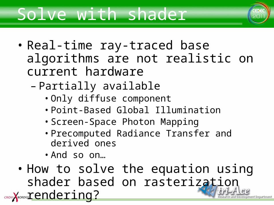
Solve with shader
• Real-time ray-traced base algorithms are not realistic on current hardware– Partially available
• Only diffuse component• Point-Based Global Illumination• Screen-Space Photon Mapping• Precomputed Radiance Transfer and derived ones• And so on…
• How to solve the equation using shader based on rasterization rendering?
Radiance in shader
• How to deal with incident radiance in shader?– A function that represents incident radiance
values from hemisphere– Texture?
• What is a radiance texture?

Radiance Texture
• A texture that stores radiance in each texel
Because x (position) is 3 dimensions, w (orientation) is 2, if the equation is used as it is, a 5 dimensional texture is necessary
If a light source is assumed to exist in infinite distance…?
dAd
dL
cos),(
2x

Radiance Environment Map (REM)
• Environment map storing radiance
Perform rendering using the radiance environment map and the rendering equation
No need to consider x, because incident light doesn’t depend on the shading point
Emission surface(dA) always faces to the center of the (environmental) sphere, cos q always becomes
1
dAd
dL
cos)(
2
∞
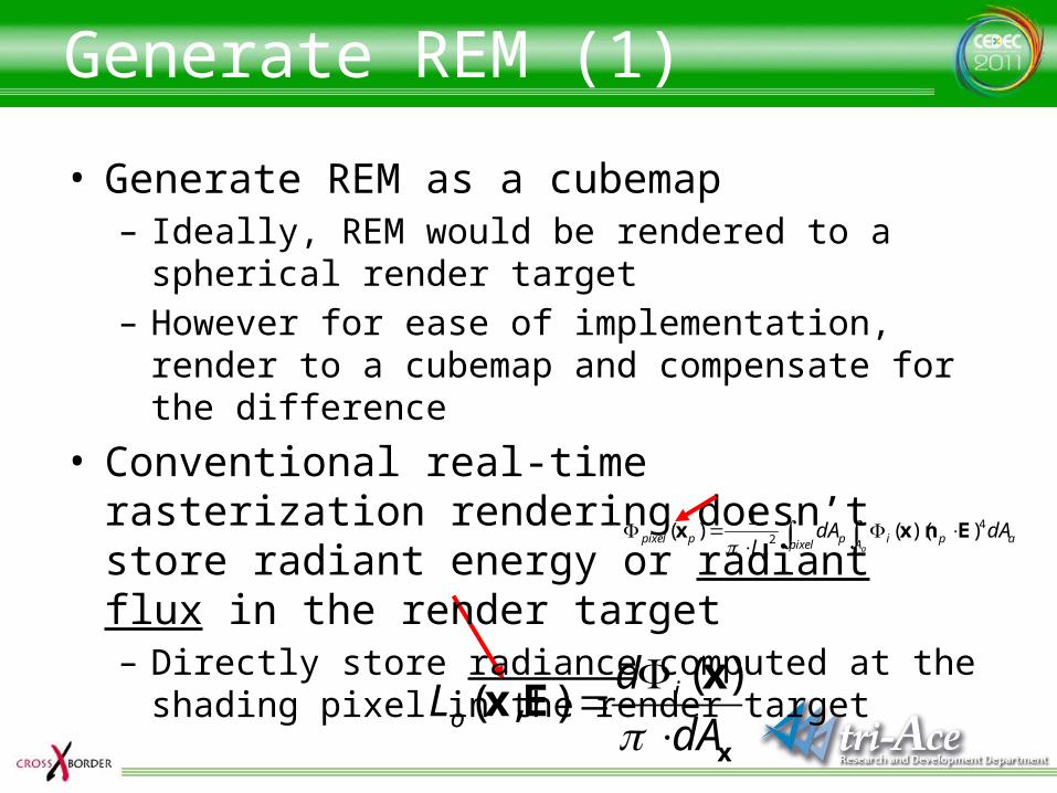
Generate REM (1)
• Generate REM as a cubemap– Ideally, REM would be rendered to a spherical render
target– However for ease of implementation, render to a
cubemap and compensate for the difference
• Conventional real-time rasterization rendering doesn’t store radiant energy or radiant flux in the render target– Directly store radiance computed at the shading pixel
in the render target
pixel A apip
a
ppixela
dAdAL
42 ))((
1)( Enxx
x
xEx
dA
dL i
o
)(),(
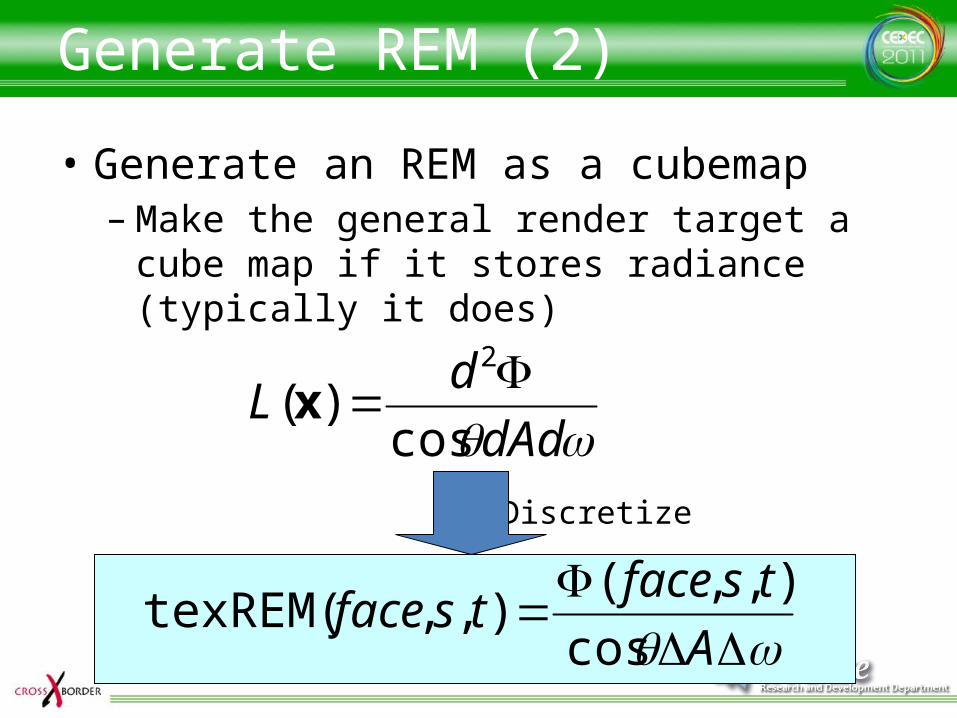
Generate REM (2)
• Generate an REM as a cubemap– Make the general render target a cube map if
it stores radiance (typically it does)
dAd
dL
cos)(
2x
A
tsfacetsface
cos
),,(),,texREM(
Discretize
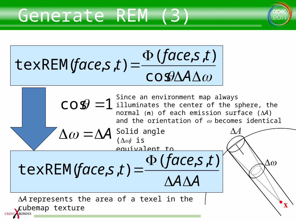
Generate REM (3)
A
tsfacetsface
cos
),,(),,texREM(
Since an environment map always illuminates the center of the sphere, the normal (n) of each emission surface (DA) and the orientation of w becomes identical
1cos
A Solid angle (Dw) isequivalent to DA
DA represents the area of a texel in the cubemap texture
AA
tsfacetsface
),,(
),,texREM(
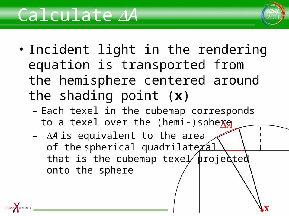
Calculate DA
• Incident light in the rendering equation is transported from the hemisphere centered around the shading point (x)– Each texel in the cubemap corresponds to a texel
over the (hemi-)sphere– DA is equivalent to the area
of the spherical quadrilateral that is the cubemap texel projected onto the sphere
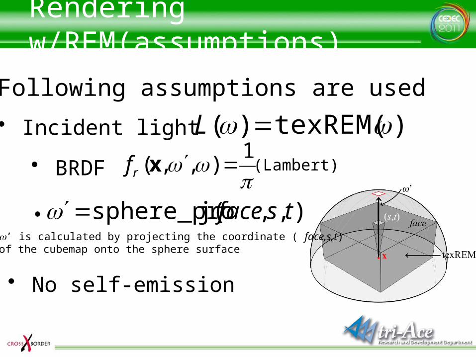
Rendering w/REM(assumptions)
)texREM()( L• Incident light
• BRDF 1
),,( xrf (Lambert)
• No self-emission
• Following assumptions are used
),,j(sphere_pro tsfacew’ is calculated by projecting the coordinate ( face,s,t)of the cubemap onto the sphere surface
•
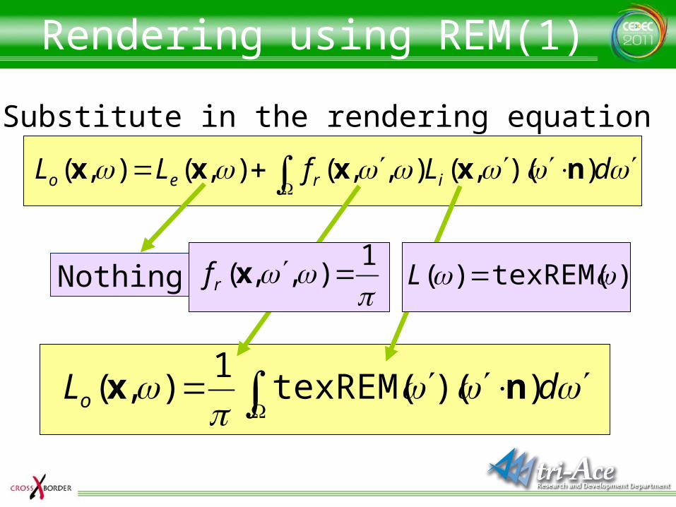
Rendering using REM(1)
Nothing
Substitute in the rendering equation
dLfLL ireo ))(,(),,(),(),( nxxxx
dLo ))(texREM(1
),( nx
1
),,( xrf )texREM()( L
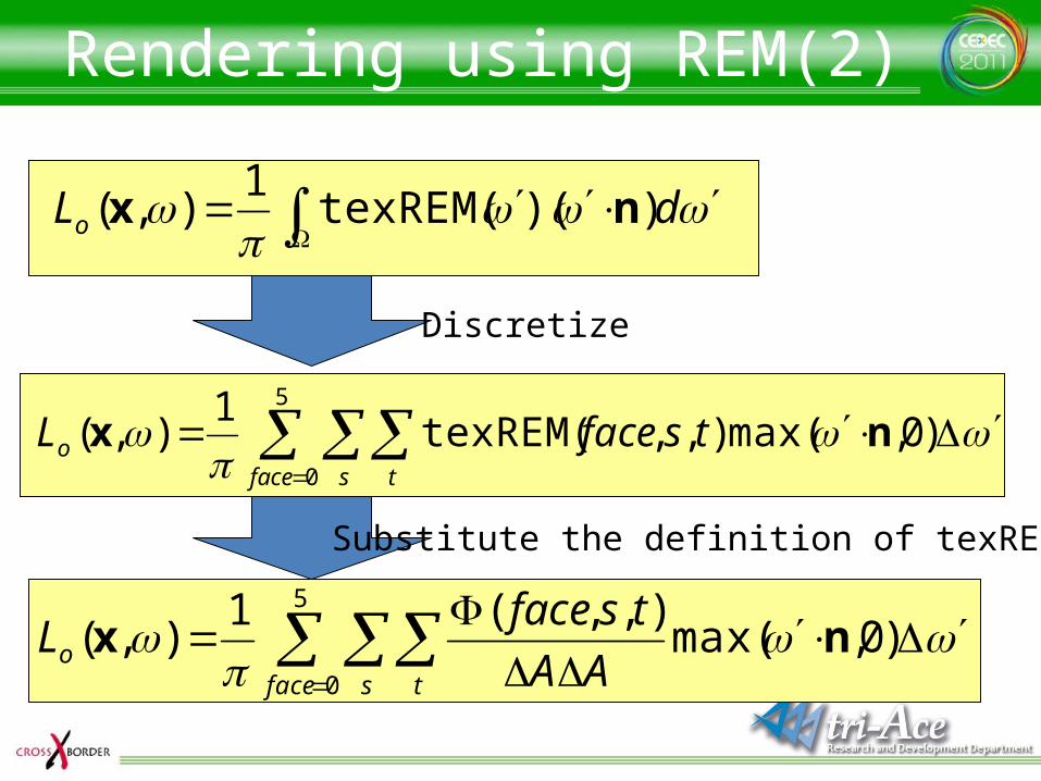
Rendering using REM(2)
Discretize
5
0
)0,max(),,texREM(1
),(face s t
o tsfaceL
nx
dLo ))(texREM(1
),( nx
Substitute the definition of texREM
5
0
)0,max(),,(1
),(face s t
o AA
tsfaceL
nx
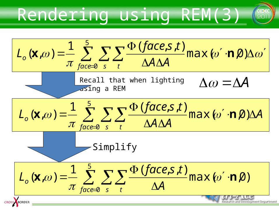
Rendering using REM(3)
Recall that when lightingusing a REM A
5
0
)0,max(),,(1
),(face s t
o AA
tsfaceL
nx
5
0
)0,max(),,(1
),(face s t
o AAA
tsfaceL nx
5
0
)0,max(),,(1
),(face s t
o A
tsfaceL nx
Simplify
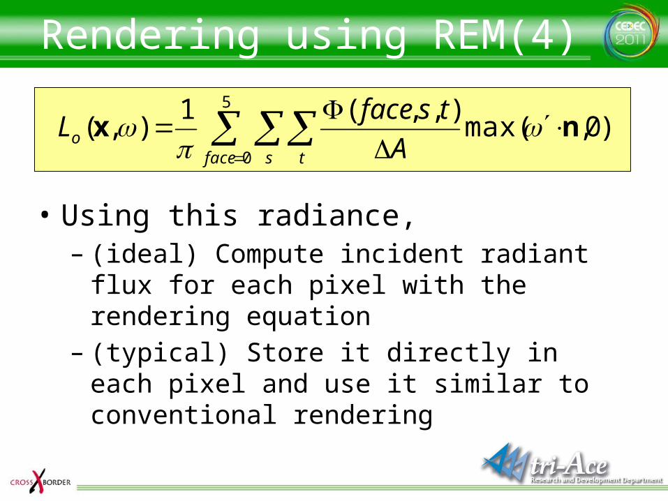
Rendering using REM(4)
• Using this radiance, – (ideal) Compute incident radiant flux for each
pixel with the rendering equation– (typical) Store it directly in each pixel and use
it similar to conventional rendering
5
0
)0,max(),,(1
),(face s t
o A
tsfaceL nx
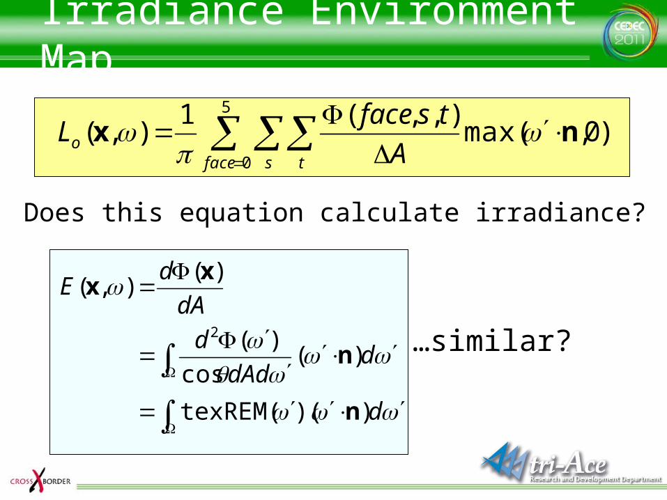
Irradiance Environment Map
Does this equation calculate irradiance?
d
ddAd
d
dA
dE
))(texREM(
)(cos
)(
)(),(
2
n
n
xx
…similar?
5
0
)0,max(),,(1
),(face s t
o A
tsfaceL nx
)0,max(),,texREM(5
0
face s t A
tsface
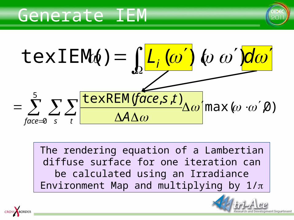
Generate IEM
The rendering equation of a Lambertian diffuse surface for one iteration can be calculated using an Irradiance Environment Map and multiplying by 1/p
dLi ))(()texIEM(
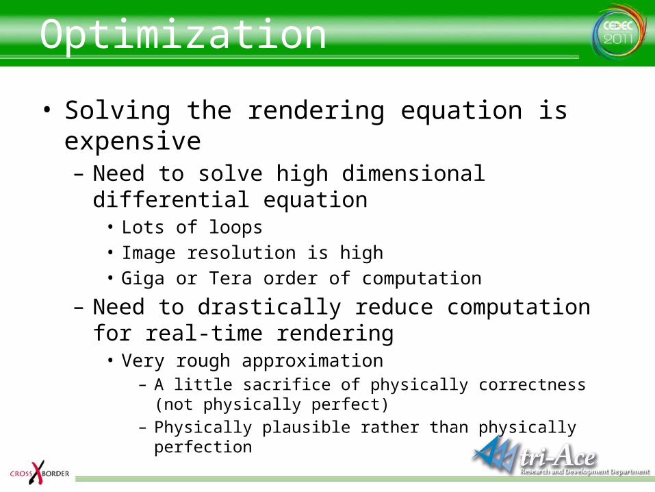
Optimization
• Solving the rendering equation is expensive– Need to solve high dimensional differential equation
• Lots of loops• Image resolution is high• Giga or Tera order of computation
– Need to drastically reduce computation for real-time rendering
• Very rough approximation– A little sacrifice of physically correctness (not physically perfect)– Physically plausible rather than physically perfection
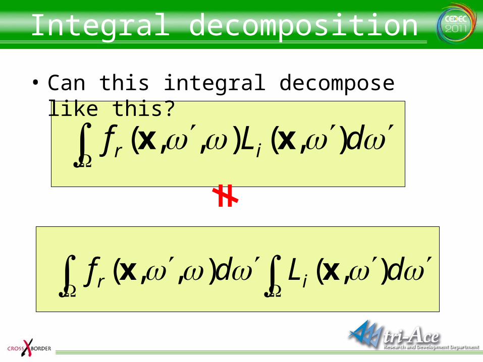
Integral decomposition
• Can this integral decompose like this?
dLf ir ),(),,( xx
dLdf ir ),(),,( xx
≠
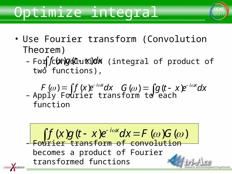
Optimize integral
• Use Fourier transform (Convolution Theorem)– For convolution (integral of product of two functions),
– Apply Fourier transform to each function
– Fourier transform of convolution becomes a product of Fourier transformed functions
dxxtgxf )()(
dxexfF xi )()( dxextgG xi )()(
)()()()( GFdxextgxf xi
Convolution theorem
• Advantage of convolution theorem– Drastic optimization using Fast Fourier
Transform (FFT)• Spherical Harmonics can be regarded as spherical
Fourier transform• Spherical Harmonics are easy to use for rendering• FFT and IFFT could have bottleneck in some cases• However, solving the rendering equation in real-time
is still too expensive on current generation hardware
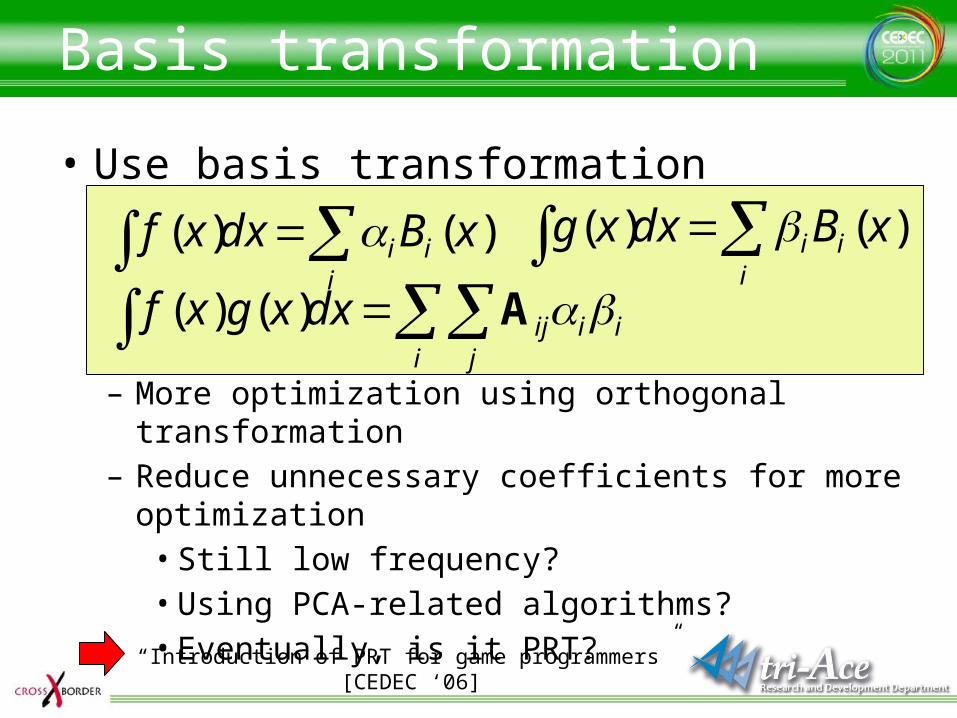
Basis transformation
• Use basis transformation
– More optimization using orthogonal transformation– Reduce unnecessary coefficients for more optimization
• Still low frequency?• Using PCA-related algorithms?• Eventually, is it PRT?
i
ii xBdxxg )()(
i j
iiijdxxgxf A)()(
“Introduction of PRT for game programmers” [CEDEC ‘06]
i
ii xBdxxf )()(
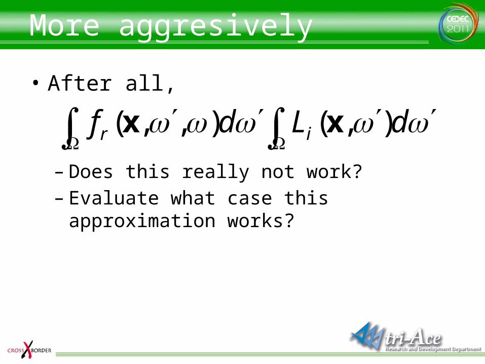
More aggresively
• After all,
– Does this really not work?– Evaluate what case this approximation works?
dLdf ir ),(),,( xx
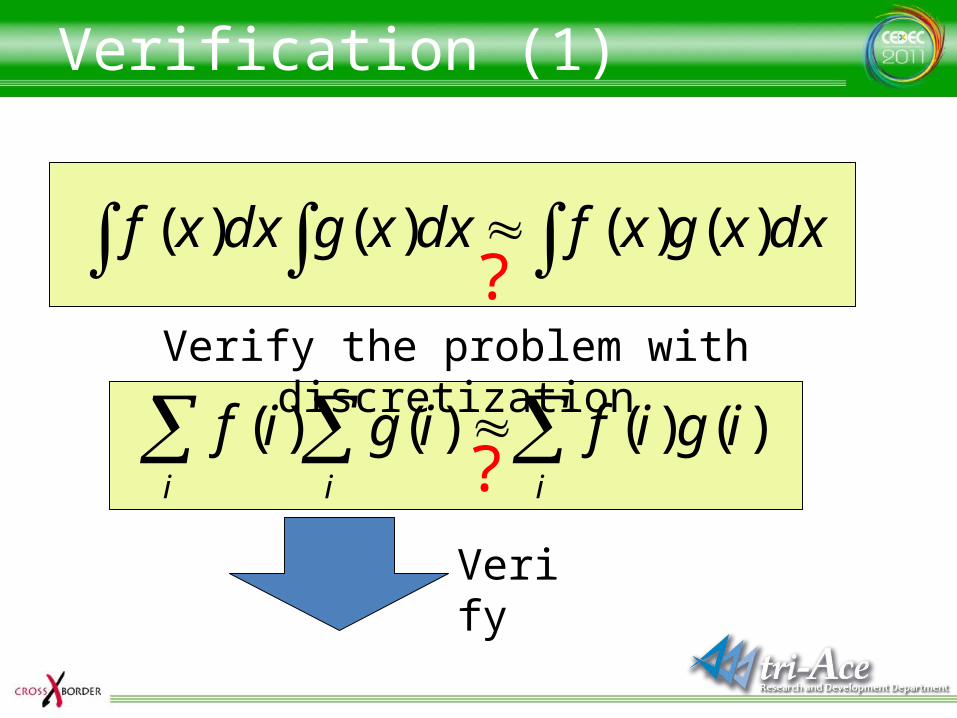
Verification (1)
dxxgxfdxxgdxxf )()()()( ?
Verify the problem with discretization
iii
igifigif )()()()(?Verify
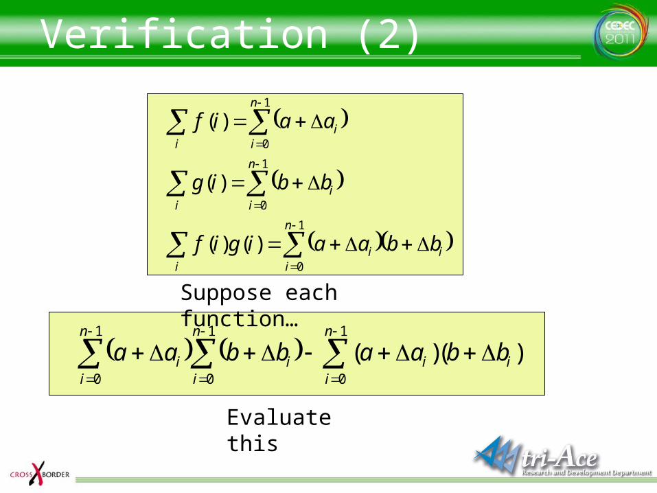
Verification (2)
)()(1
0
1
0
1
0i
n
ii
n
ii
n
ii bbaabbaa
1
0
1
0
1
0
)()(
)(
)(
n
iii
i
n
ii
i
n
ii
i
bbaaigif
bbig
aaif
Suppose each function…
Evaluate this
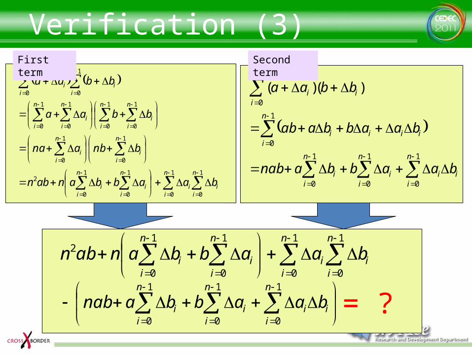
Verification (3)
1
0
1
0
1
0
1
0
2
1
0
1
0
1
0
1
0
1
0
1
0
1
0
1
0
n
ii
n
ii
n
ii
n
ii
n
ii
n
ii
n
ii
n
i
n
ii
n
i
n
ii
n
ii
baabbanabn
bnbana
bbaa
bbaa
First term
i
n
ii
n
ii
n
ii
n
iiiii
i
n
ii
baabbanab
baabbaab
bbaa
1
0
1
0
1
0
1
0
1
0
)()(
Second term
1
0
1
0
1
0
1
0
2n
ii
n
ii
n
ii
n
ii baabbanabn
i
n
ii
n
ii
n
ii baabbanab
1
0
1
0
1
0= ?
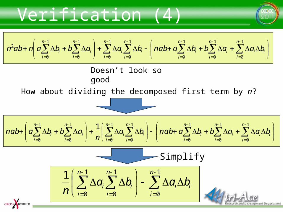
Verification (4)
i
n
ii
n
ii
n
ii
n
ii
n
ii
n
ii
n
ii baabbanabbaabbanabn
1
0
1
0
1
0
1
0
1
0
1
0
1
0
2
Doesn’t look so good
How about dividing the decomposed first term by n?
i
n
ii
n
ii
n
ii
n
ii
n
ii
n
ii
n
ii baabbanabba
nabbanab
1
0
1
0
1
0
1
0
1
0
1
0
1
0
1
i
n
ii
n
ii
n
ii baba
n
1
0
1
0
1
0
1
Simplify
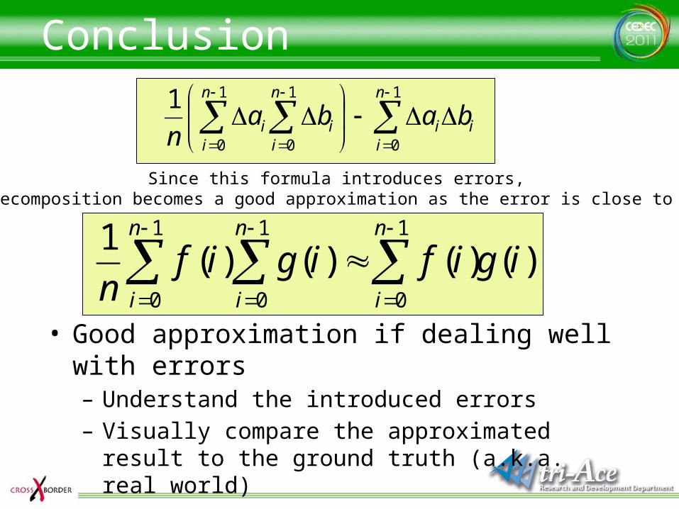
Conclusion
i
n
ii
n
ii
n
ii baba
n
1
0
1
0
1
0
1
Since this formula introduces errors,the decomposition becomes a good approximation as the error is close to zero
)()()()(1 1
0
1
0
1
0
igifigifn
n
i
n
i
n
i
• Good approximation if dealing well with errors– Understand the introduced errors– Visually compare the approximated result to the
ground truth (a.k.a. real world)
Wrap up
• It is naturally possible to achieve physically correct rendering by using the rendering equation– Because the integration is computed in the
code,• It is fair enough to correctly write down the
required conditions in mathematical form
– Neccesary calculations are not difficult• Drastic optimization according to requirements by
hardware specification– Compromised and rough approximation for some cases
Acknowledgements
• R&D department, tri-Ace, Inc.– Tatsuya Shoji– Satoshi Ishii– Takafumi Ohshima– Elliott Davis
• Thanks for the English version– Sébastien Lagarde, Marc Heng
and Naty Hoffman

Questions?
http://research.tri-ace.com


![The Iray Light Transport Simulation and Rendering System...Iray light transport simulation and rendering system [Iray] allows for rendering complex scenes by the push of a button and](https://cdn.vdocuments.net/doc/165x107/60f9158832e4cf1d3a2b60af/the-iray-light-transport-simulation-and-rendering-system-iray-light-transport.jpg)


