
Plasmon slot waveguides : Metal-Insulator-Metal (MIM)
Plasmon slot waveguides: Towards chip-scale propagation with subwavelength-scale localization
J. A. Dionne,* L. A. Sweatlock, and H. A. Atwater (caltech, USA)
Phy. Rev. B, Vol.73, 035407 (2006)
Insulator 1x
z
y
Metal 2
Metal 2
d

Insulator 1x
z
y
Metal 2
Metal 2
d
( ,0, ) (0, ,0)x z yE E E B B
(0, ,0) ( ,0, )y x zE E B B B

Mode L+ Mode L-
Tangential (Ex)Electric Field Profiles
(TM modes)

ab : antisymmetric bound
sb : Symmetric bound
(infinite d)
(infinite d)
Tangential (Ex)Electric Field Profiles
Insulator 1x
z
y
Metal 2
Metal 2
d
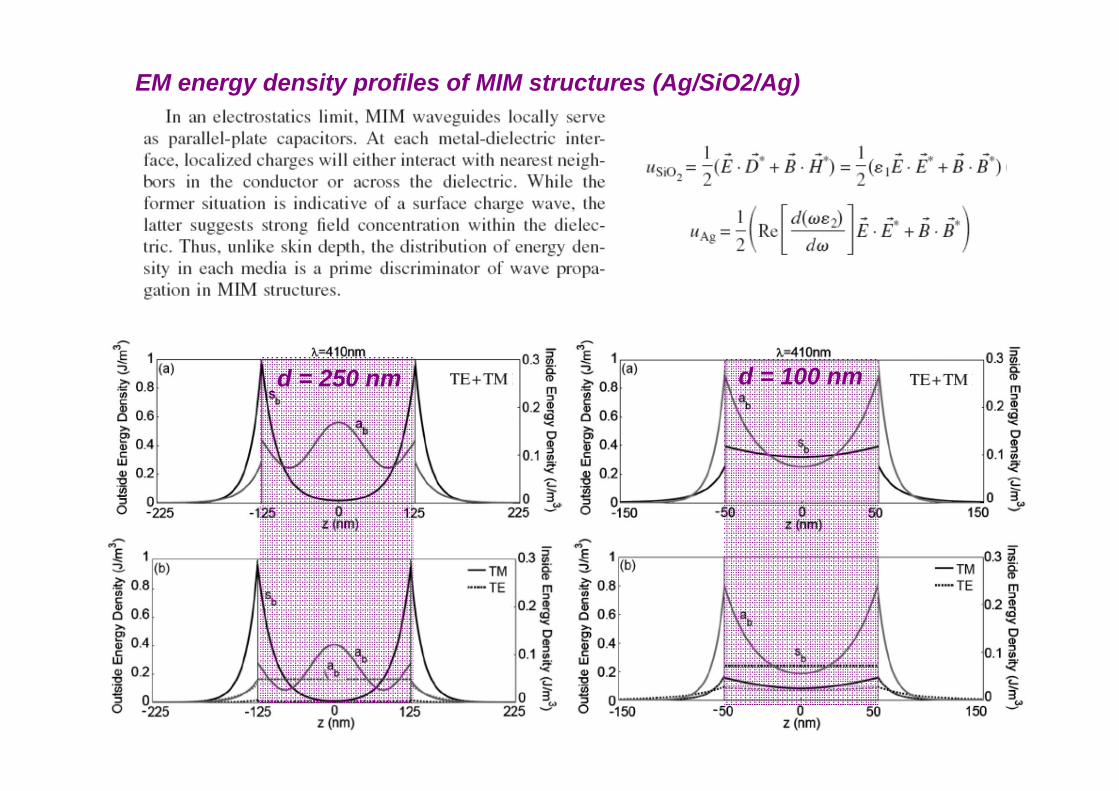
d = 100 nm
d = 250 nm

(infinite d)IMI MIM

(infinite d)
conventional waveguide modesIn SiO2 core
SP modes
SP modes
D = 250 nmab sb

(infinite d)
conventional waveguide modeswithin E ~ 1 eV
SP modes
D = 100 nm
Sb

The dispersion of the 50-nm-thick sample lies completely to the left of the decoupled SP mode.Low-energy asymptotic behavior follows a light line of n = 1.5.It suggests that polariton modes of MIM more highly sample the imaginary dielectric component.In the low energy limit, the Sb SP truly represent a photon trapped on the metal surface.
sb SP : D = 50 nm 30 nm 25 nm 12 nm
Insulator 1x
z
y
Metal 2
Metal 2
d

ab SP :
Purely plasmonic nature of the mode
The cutoff frequencies remains essentially unchanged, possibly by the Goos-Hanchen effect. As waveguide dimensions are decreased, energy densities are more highly concentrated at the metal surface. This enhanced field magnifies Goss-Hanchen contributions significantly.In the limit of d << s (skin depth), complete SP dephasing could result.
D = 50 nm 30 nm 25 nm 12 nm

( D = 250 nm )MIM (Ag/SiO2/Ag) TM-polarized propagation and skin depth
Forbidden band
ab
sb
Note that only a slight relation correlation between propagation distance and skin depth ().
The metal absorption is not the limiting loss mechanism in MIM structures.
(infinite d)80 m
15 m
20 nm

( D = 12 nm, 20 nm, 35 nm, 50 nm, and 100 nm )MIM (Ag/SiO2/Ag) TM-polarized propagation and skin depth
ab sb
~ 20 nm
Evanescent within 10 nmfor all wavelengthApproximately constant in the Ag cladding.
Thus, MIM can achieve micron-scale propagation with nanometer-scale confinement.
Local minima corresponding to the transition between quasibound modes and radiation modes
Unlike IMI, extinction (prop. distance) is determined not by ohmic loss (metal absorption)but by field interference upon phase shifts induced by the metal.

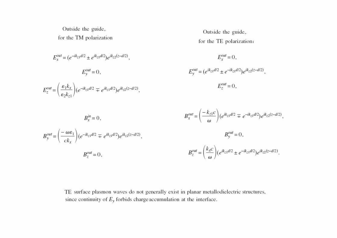
TE modes in MIM structures
(~ 4 eV: ~300 nm)
d = 250 nm d = 100 nm
EM energy density profiles of MIM structures (Ag/SiO2/Ag)


Geometries and materialsfor subwavelength surface plasmon modes
Rashid Zia, Mark D. Selker, Peter B. Catrysse, and Mark L. Brongersma
J. Opt. Soc. Am. A/Vol. 21, No. 12/December 2004, 2442-2446.
We demonstrate that, to achieve subwavelength pitches, a metal–insulator–metal geometry is required
with higher confinement factors and smaller spatial extentthan conventional insulator–metal–insulator structures.
The resulting trade-off between propagation and confinement for surface plasmons is discussed,
and optimization by materials selection is described.

Consider the isotropic wave equation for a generic three-layer plasmonic slab waveguide with metallic and dielectric regions,
For a guided surface-plasmon mode to exist,
where z is the propagation direction and thus kz is the conserved quantity.
If the radiation is unconfined in the y dimension (i.e., k y = 0),

Confinement of the MIM structure is limited by the decay length into the metallic regions,which can be approximated as follows for metals below the surface-plasmon resonance:
Note that this condition is met only near the surface plasmon resonance frequency.
Ultimate confinement of the IMI structure is limited by the decay length into the dielectric cladding. For confinement below the limit of a conventional dielectric waveguide (/2n),
2x (1/kx,dielectric ) < (/2n)
1/ 22
1/ 2,
metalx metal d
metal d
kc c
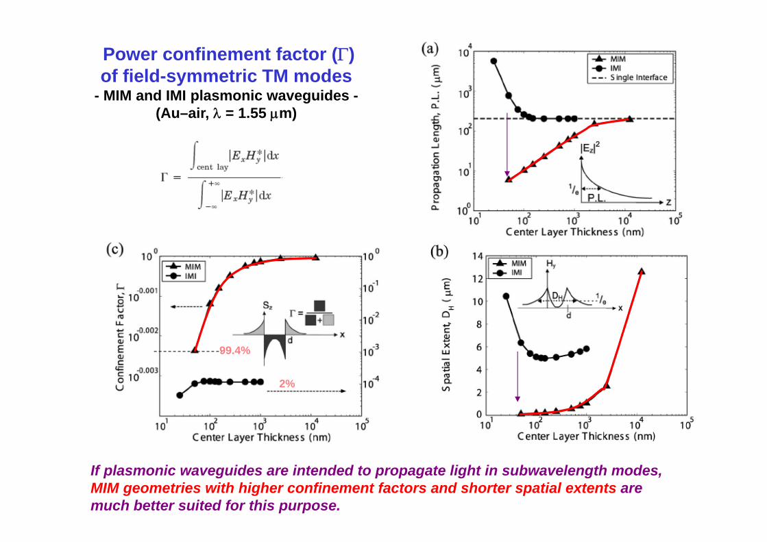
Power confinement factor () of field-symmetric TM modes
- MIM and IMI plasmonic waveguides -(Au–air, = 1.55 m)
99.4%
2%
If plasmonic waveguides are intended to propagate light in subwavelength modes, MIM geometries with higher confinement factors and shorter spatial extents are much better suited for this purpose.


2007/5/1 ~
an optical range resonator based on single mode metal-insulator-metal plasmonic gap waveguides. A small bridge between the resonator and the input waveguide can be used to tune the resonance frequency.
FDTD with the perfectly matched layer boundary conditions


