Preface, Contents
CPUs 1CPU 31x-2 as DP Master/DPSlave and Direct Communication 2
Cycle and Reaction times 3CPU Function, depending onCPU and STEP 7 Version 4
Tips and Tricks 5
Appendix
Standards, Certificates andApprovals A
Dimensioned Drawings B
List of Abbreviations C
Glossary, Index
Edition 10/2001A5E00111190-01
PLC S7-300,CPU Specifications CPU 312 IFMto CPU 318-2 DP
Reference Manual
SIMATIC
This manual is part of the documentationpackage with the order number 6ES7398-8FA10-8BA0
This documentation can no longer be ordered under the given number!

Index-2PLC S7-300, CPU Specifications CPU 312 IFM to CPU 318-2 DP
A5E00111190-01
!Danger
indicates that death, severe personal injury or substantial property damage will result if proper precautionsare not taken.
!Warning
indicates that death, severe personal injury or substantial property damage can result if properprecautions are not taken.
!Caution
indicates that minor personal injury can result if proper precautions are not taken.
Caution
indicates that property damage can result if proper precautions are not taken.
Notice
draws your attention to particularly important information on the product, handling the product, or to aparticular part of the documentation.
Qualified PersonnelOnly qualified personnel should be allowed to install and work on this equipment. Qualified persons aredefined as persons who are authorized to commission, to ground and to tag circuits, equipment, andsystems in accordance with established safety practices and standards.
Correct UsageNote the following:
!Warning
This device and its components may only be used for the applications described in the catalog or thetechnical description, and only in connection with devices or components from other manufacturers whichhave been approved or recommended by Siemens.
This product can only function correctly and safely if it is transported, stored, set up, and installedcorrectly, and operated and maintained as recommended.
TrademarksSIMATIC, SIMATIC HMI and SIMATIC NET are registered trademarks of SIEMENS AG.
Third parties using for their own purposes any other names in this document which refer to trademarksmight infringe upon the rights of the trademark owners.
Safety GuidelinesThis manual contains notices intended to ensure personal safety, as well as to protect the products andconnected equipment against damage. These notices are highlighted by the symbols shown below andgraded according to severity by the following texts:
We have checked the contents of this manual for agreementwith the hardware and software described. Since deviationscannot be precluded entirely, we cannot guarantee fullagreement. However, the data in this manual are reviewedregularly and any necessary corrections included insubsequent editions. Suggestions for improvement arewelcomed.
Disclaim of LiabilityCopyright � Siemens AG 2001 All rights reserved
The reproduction, transmission or use of this document or itscontents is not permitted without express written authority.Offenders will be liable for damages. All rights, including rightscreated by patent grant or registration of a utility model ordesign, are reserved.
Siemens AGBereich Automatisierungs- und AntriebstechnikGeschaeftsgebiet Industrie-AutomatisierungssystemePostfach 4848, D- 90327 Nuernberg
Siemens AG 2001Technical data subject to change.
Siemens Aktiengesellschaft A5E00111190

iiiPLC S7-300, CPU Specifications CPU 312 IFM to CPU 318-2 DPA5E00111190-01
Preface
Purpose of the Manual
This manual gives you a brief overview of 312 IFM to 318-2 CPUS in an S7-300.You can look up information on how to operate the system, its functions andtechnical data of the CPUs.
Essential know-how
General knowledge of automation technology is required for comprehension of thisManual. You should also be acquainted with basic STEP 7 software as describedin your Programming with STEP 7 V 5.1 Manual.

Preface
ivPLC S7-300, CPU Specifications CPU 312 IFM to CPU 318-2 DP
A5E00111190-01
Scope of the Manual
The manual covers the following CPUs and Hardware/Software versions:
CPU Order No. As of Version
Firmware Hardware
CPU 312 IFM 6ES7 312-5AC02-0AB0
6ES7 312-5AC82-0AB0
1.1.0 01
CPU 313 6ES7 313-1AD03-0AB0 1.1.0 01
CPU 314 6ES7 314-1AE04-0AB0
6ES7 314-1AE84-0AB0
1.1.0 01
CPU 314 IFM 6ES7 314-5AE03-0AB06ES7 314-5AE83-0AB0
1.1.0 01
CPU 314 IFM 6ES7 314-5AE10-0AB0 1.1.0 01
CPU 315 6ES7 315-1AF03-0AB0 1.1.0 01
CPU 315-2 DP 6ES7 315-2AF03-0AB06ES7 315-2AF83-0AB0
1.1.0 01
CPU 316-2 DP 6ES7 316-2AG00-0AB0 1.1.0 01
CPU 318-2 6ES7 318-2AJ00-0AB0 V3.0.0 03
This manual describes all modules that are valid at the time the manual isreleased. We reserve the right to release product information for new modules ornew module versions.
Alterations from Previous Version
The following changes were made in the Structuring, CPU Data Manual, Order no.6ES7398-8AA03-8BA0, Edition 2:
� Now, this manual only contains the CPU description. For information on theS7-300 structure and installation refer to the Installation Manual.
� CPU 318-2 DP as of Firmware Version V3.0.0 behaves as DP Master accordingto PROFIBUS DPV1.
Agreement for CPU 314IFM
The CPU 314IFM is available in 2 versions:
� with slot for Memory Card (6ES7314-5EA10-0AB0)
� without slot for Memory Card (6ES7314-5EA0x-0AB0)
All details in this chapter apply to both versions of CPU 314IFM, unless explicitreference is made to differences between them.

Preface
vPLC S7-300, CPU Specifications CPU 312 IFM to CPU 318-2 DPA5E00111190-01
Approbation, Standards and Approvals
The SIMATIC S7-300 series conforms to:
� Requirements and criteria to IEC 61131, Part 2
� CE labeling
– EC Guideline 73/23/EEC on Low Voltages
– EC Guideline 89/336/EEC on electromagnetic compatibility (EMC)
� Canadian Standards Association: CSA C22.2 Number 142, tested (ProcessControl Equipment)
� Underwriters Laboratories, Inc.: UL 508 registered (Industrial ControlEquipment)
� Underwriters Laboratories, Inc.: UL 508 (Industrial Control Equipment)
� Factory Mutual Research: Approval Standard Class Number 3611
� C-Tick Australia

Preface
viPLC S7-300, CPU Specifications CPU 312 IFM to CPU 318-2 DP
A5E00111190-01
Integration in the Information Technology Environment
This Manual forms part of the S7-300 documentation package:
Reference Manual “CPU Data”
CPU Data of CPU 312 IFM to 318-2 DP
CPU Data of CPU 312C to 314C-2 PtP/DP
“Technological Functions” Manual
Manual
Samples
Installation Manual
Manual
Reference Manual “Module Data”
Manual
Operations List“CPU 312 IFM, 314 IFM, 313, 315,315-2 DP, 316-2 DP, 318-2 DP”
“CPUs 312C to 314C-2 PtP/DP
Getting Started
“S7-300”
Description on how to operate, of the functionsand of technical data of the CPU
Description of specific technologicalfunctions:
� Positioning
� Counting
� Point-to-point connection
� Rules
The CD contains examples oftechnological functions
Description of how to create a project and howto install, wire, network and commission anS7-300
Description and technological details of signal modules, power supplymodules and interface modules
List of the CPU’s system resources andtheir execution times.Listing of all runtime function blocks (OBs/SFCs/SFBs) and their execution times
the various Getting Started manuals offer helpfor commissioning your applications
“CPU 31xC:Positioning with Analog Output”
“CPU 31xC: Positioning with Digital Outputs”
“CPU 31xC: Counting”
“CPU 31xC: Point-to-point Communication
“CPU 31xC: Controlling”
“CPU 31xC:
You
are
rea
ding
this
man
ual
Figure 1-1 S7-300, information technology environment

Preface
viiPLC S7-300, CPU Specifications CPU 312 IFM to CPU 318-2 DPA5E00111190-01
Complementary to this documentation package you require the following manuals:
Manual “Integrated Functions CPU 312 IFM/314 IFM”
Manual
Order no.: 6ES7398-8CA00-8BA0
Reference Manual “System Software forS7-300/400 System and Standard Functions”
Reference manual
Part of the STEP 7 documentation package,order no. 6ES7810-4CA05-8BR0
Description of technological functions of theCPUs 312 IFM/314 IFM.
Description of the SFCs, SFBs and OBs of theCPUs. This description is also available in theSTEP 7 Online Help.
Figure 1-2 Additional Documentation
Further Support
Please contact your local Siemens representative if you have any queries aboutthe products described in this manual.
http://www.ad.siemens.de/partner
Training Center
Newcomers to SIMATIC S7 PLCs are welcome to take part in our respectivetraining courses. Please contact your local Training Center, or the central TrainingCenter in D-90327 Nuremberg, Germany:
Phone: +49 (911) 895-3200.
http://www.sitrain.com

Preface
viiiPLC S7-300, CPU Specifications CPU 312 IFM to CPU 318-2 DP
A5E00111190-01
Automation and Drives, Service & Support
World-wide available 24-hours:
Johnson City
Nuremberg
Singapore
SIMATIC Hotline
World-wide (Nuremberg)
Technical Support
(Free Contact)
Local time: Mo.-Fr. 7:00AM to 17:00 PM
Phone: +49 (180) 5050-222
Fax: +49 (180) 5050-223
E-mail: [email protected]
GMT: +1:00
World-wide (Nuremberg)
Technical Support
(charged, only with SIMATIC Card)Local time: Mo.-Fr. 0:00 AM to24:00 PM
Phone: +49 (911) 895-7777
Fax: +49 (911) 895-7001
GMT: +01:00
Europe / Africa (Nuremberg)
Authorization
Local time: Mo.-Fr. 7:00AM to 17:00 PM
Phone: +49 (911) 895-7200
Fax: +49 (911) 895-7201
E-mail: [email protected]
GMT: +1:00
America (Johnson City)
Technical Support andAuthorizationLocal time: Mo.-Fr. 8:00 AM to19:00 PM
Phone: +1 423 262-2522
Fax: +1 423 262-2289
E-mail: [email protected]
GMT: -5:00
Asia / Australia (Singapore)
Technical Support andAuthorizationLocal time: Mo.-Fr. 8:30 AM to17:30 PM
Phone: +65 740-7000
Fax: +65 740-7001
E-mail: [email protected]
GMT: +8:00
Languages generally spoken at the SIMATIC Hotlines are German and English. Additional languages spoken at theAuthorization Hotline are French, Italian and Spanish.
Preface
ixPLC S7-300, CPU Specifications CPU 312 IFM to CPU 318-2 DPA5E00111190-01
SIMATIC Documentation on the Internet
Documentation is available free of charge on the Internet under:
http://www.ad.siemens.de/support
Please use the Knowledge Manager offered at these locations for quick location ofyour required documentation. Our Internet Forum offers a “Documentation”conferencing room for your questions and solution proposals.
http://www.ad.siemens.de/support
Service & Support on the Internet
As a supplement to our provided documentation we offer our complete know-howbase on the Internet.
http://www.ad.siemens.de/support
There you will find:
� Up-to-date product information (News), FAQs (Frequently Asked Questions),Downloads, Tips and Tricks.
� Our Newsletter always offers you the most up-to-date information on yourproducts.
� The Knowledge Manager finds the right documents for you.
� Users and specialists across the globe share their experiences in our Forum.
� Your local service partner for Automation & Drives is found in our ServicePartner Database.
� Information relating to on–site Service, repairs, spare parts and lots more isavailable to you under the topic “Service”.

Preface
xPLC S7-300, CPU Specifications CPU 312 IFM to CPU 318-2 DP
A5E00111190-01

xiPLC S7-300, CPU Specifications CPU 312 IFM to CPU 318-2 DPA5E00111190-01
Contents
1 CPUs
1.1 Control and Display Elements 1-2 . . . . . . . . . . . . . . . . . . . . . . . . . . . . . . . . . . . . . 1.1.1 Status and Fault Displays 1-3 . . . . . . . . . . . . . . . . . . . . . . . . . . . . . . . . . . . . . . . . 1.1.2 Mode Selector Switch 1-4 . . . . . . . . . . . . . . . . . . . . . . . . . . . . . . . . . . . . . . . . . . . . 1.1.3 Backup battery/accumulator 1-5 . . . . . . . . . . . . . . . . . . . . . . . . . . . . . . . . . . . . . . 1.1.4 Memory card 1-6 . . . . . . . . . . . . . . . . . . . . . . . . . . . . . . . . . . . . . . . . . . . . . . . . . . . 1.1.5 MPI and PROFIBUS-DP Interface 1-7 . . . . . . . . . . . . . . . . . . . . . . . . . . . . . . . . . 1.1.6 Clock and Runtime Meter 1-10 . . . . . . . . . . . . . . . . . . . . . . . . . . . . . . . . . . . . . . . . .
1.2 Communication Options of the CPU 1-11 . . . . . . . . . . . . . . . . . . . . . . . . . . . . . . .
1.3 Test Functions and Diagnostics 1-19 . . . . . . . . . . . . . . . . . . . . . . . . . . . . . . . . . . . 1.3.1 Testing Functions 1-19 . . . . . . . . . . . . . . . . . . . . . . . . . . . . . . . . . . . . . . . . . . . . . . . 1.3.2 Diagnostics with LED Display 1-22 . . . . . . . . . . . . . . . . . . . . . . . . . . . . . . . . . . . . . 1.3.3 Diagnostics with STEP 7 1-22 . . . . . . . . . . . . . . . . . . . . . . . . . . . . . . . . . . . . . . . . .
1.4 CPUs - Technical Specifications 1-24 . . . . . . . . . . . . . . . . . . . . . . . . . . . . . . . . . . . 1.4.1 CPU 312 IFM 1-25 . . . . . . . . . . . . . . . . . . . . . . . . . . . . . . . . . . . . . . . . . . . . . . . . . . . 1.4.2 CPU 313 1-37 . . . . . . . . . . . . . . . . . . . . . . . . . . . . . . . . . . . . . . . . . . . . . . . . . . . . . . . 1.4.3 CPU 314 1-40 . . . . . . . . . . . . . . . . . . . . . . . . . . . . . . . . . . . . . . . . . . . . . . . . . . . . . . . 1.4.4 CPU 314IFM 1-43 . . . . . . . . . . . . . . . . . . . . . . . . . . . . . . . . . . . . . . . . . . . . . . . . . . . 1.4.5 CPU 315 1-60 . . . . . . . . . . . . . . . . . . . . . . . . . . . . . . . . . . . . . . . . . . . . . . . . . . . . . . . 1.4.6 CPU 315-2 DP 1-63 . . . . . . . . . . . . . . . . . . . . . . . . . . . . . . . . . . . . . . . . . . . . . . . . . . 1.4.7 CPU 316-2 DP 1-66 . . . . . . . . . . . . . . . . . . . . . . . . . . . . . . . . . . . . . . . . . . . . . . . . . . 1.4.8 CPU 318-2 1-69 . . . . . . . . . . . . . . . . . . . . . . . . . . . . . . . . . . . . . . . . . . . . . . . . . . . . .
2 CPU 31x-2 as DP Master/DP Slave and Direct Communication
2.1 Information on DPV1 Functionality 2-2 . . . . . . . . . . . . . . . . . . . . . . . . . . . . . . . . .
2.2 DP Address Areas of the CPUs 31x-2 2-4 . . . . . . . . . . . . . . . . . . . . . . . . . . . . . .
2.3 CPU 31x-2 as DP Master 2-5 . . . . . . . . . . . . . . . . . . . . . . . . . . . . . . . . . . . . . . . . .
2.4 Diagnostics of the CPU 31x-2 as DP Master 2-6 . . . . . . . . . . . . . . . . . . . . . . . .
2.5 CPU 31x-2 as DP-Slave 2-13 . . . . . . . . . . . . . . . . . . . . . . . . . . . . . . . . . . . . . . . . . .

Contents
xiiPLC S7-300, CPU Specifications CPU 312 IFM to CPU 318-2 DP
A5E00111190-01
2.6 Diagnosis of the CPU 31x-2 operating as DP-Slave 2-18 . . . . . . . . . . . . . . . . . . 2.6.1 Diagnosis with LEDs 2-19 . . . . . . . . . . . . . . . . . . . . . . . . . . . . . . . . . . . . . . . . . . . . . 2.6.2 Diagnostics with STEP 5 or STEP 7 2-19 . . . . . . . . . . . . . . . . . . . . . . . . . . . . . . . 2.6.3 Reading Out the Diagnostic Data 2-20 . . . . . . . . . . . . . . . . . . . . . . . . . . . . . . . . . . 2.6.4 Format of the Slave Diagnostic Data 2-24 . . . . . . . . . . . . . . . . . . . . . . . . . . . . . . . 2.6.5 Station Status 1 to 3 2-25 . . . . . . . . . . . . . . . . . . . . . . . . . . . . . . . . . . . . . . . . . . . . . 2.6.6 Master PROFIBUS Address 2-27 . . . . . . . . . . . . . . . . . . . . . . . . . . . . . . . . . . . . . . 2.6.7 Manufacturer ID 2-27 . . . . . . . . . . . . . . . . . . . . . . . . . . . . . . . . . . . . . . . . . . . . . . . . . 2.6.8 Module Diagnostics 2-28 . . . . . . . . . . . . . . . . . . . . . . . . . . . . . . . . . . . . . . . . . . . . . . 2.6.9 Station Diagnostics 2-29 . . . . . . . . . . . . . . . . . . . . . . . . . . . . . . . . . . . . . . . . . . . . . . 2.6.10 Interrupts 2-31 . . . . . . . . . . . . . . . . . . . . . . . . . . . . . . . . . . . . . . . . . . . . . . . . . . . . . . .
2.7 Direct Data Exchange 2-32 . . . . . . . . . . . . . . . . . . . . . . . . . . . . . . . . . . . . . . . . . . . .
2.8 Diagnosis with Direct Communication 2-33 . . . . . . . . . . . . . . . . . . . . . . . . . . . . . .
3 Cycle and Reaction times
3.1 Cycle time 3-2 . . . . . . . . . . . . . . . . . . . . . . . . . . . . . . . . . . . . . . . . . . . . . . . . . . . . . .
3.2 Response Time 3-3 . . . . . . . . . . . . . . . . . . . . . . . . . . . . . . . . . . . . . . . . . . . . . . . . .
3.3 Calculation Examples for Cycle Time and Response Time 3-10 . . . . . . . . . . . .
3.4 Interrupt response time 3-14 . . . . . . . . . . . . . . . . . . . . . . . . . . . . . . . . . . . . . . . . . .
3.5 Calculation Example for the Interrupt Response Time 3-16 . . . . . . . . . . . . . . . .
3.6 Reproducibility of Delay and Watchdog Interrupts 3-16 . . . . . . . . . . . . . . . . . . . .
4 CPU Function, depending on CPU and STEP 7 Version
4.1 Differences between CPU 3182 and CPUs 312 IFM to 3162 DP 4-2 . . . . . . .
4.2 The Differences Between the CPUs 312 IFM to 318 and Their Previous Versions 4-6 . . . . . . . . . . . . . . . . . . . . . . . . . . . . . . . . . . . . . . . . . .
5 Tips and Tricks
A Standards, Certificates and Approvals
B Dimensioned Drawings
C List of Abbreviations
Glossary
Index

Contents
xiiiPLC S7-300, CPU Specifications CPU 312 IFM to CPU 318-2 DPA5E00111190-01
Figures
1-1 Control and Display Elements of the CPUs 1-2 . . . . . . . . . . . . . . . . . . . . . . . . . 1-2 Status and Fault Displays of the CPUs 1-3 . . . . . . . . . . . . . . . . . . . . . . . . . . . . . 1-3 Principle of Connection Resource Allocation for CPU 318-2 1-15 . . . . . . . . . . . 1-4 The Principle of Forcing with S7-300 CPUs (CPU 312IFM to 316-2DP) 1-21 . 1-5 Display of the States of the Interrupt Inputs of the CPU 312 IFM 1-26 . . . . . . . 1-6 Front View of the CPU 312 IFM 1-27 . . . . . . . . . . . . . . . . . . . . . . . . . . . . . . . . . . . 1-7 Wiring diagram of the CPU 312 IFM 1-34 . . . . . . . . . . . . . . . . . . . . . . . . . . . . . . . 1-8 Basic Circuit Diagram of the CPU 312 IFM 1-36 . . . . . . . . . . . . . . . . . . . . . . . . . . 1-9 Display of the States of the Interrupt Inputs of the CPU 314 IFM 1-45 . . . . . . . 1-10 Front View of the CPU 314 IFM 1-46 . . . . . . . . . . . . . . . . . . . . . . . . . . . . . . . . . . . 1-11 Wiring diagram of the CPU 314 IFM 1-56 . . . . . . . . . . . . . . . . . . . . . . . . . . . . . . . 1-12 Basic Circuit Diagram of the CPU 314 IFM (Special Inputs
and Analog Inputs/Outputs) 1-57 . . . . . . . . . . . . . . . . . . . . . . . . . . . . . . . . . . . . . . . 1-13 Basic Circuit Diagram of the CPU 314 IFM (Digital Inputs/Outputs) 1-58 . . . . . 1-14 Connecting 2-wire measurement transducers to the analog inputs
of CPU 314 IFM 1-59 . . . . . . . . . . . . . . . . . . . . . . . . . . . . . . . . . . . . . . . . . . . . . . . . . 1-15 Wiring of 4-wire measurement transducers to the analog inputs
of CPU 314 IFM 1-59 . . . . . . . . . . . . . . . . . . . . . . . . . . . . . . . . . . . . . . . . . . . . . . . . . 2-1 Diagnostics with CPU 315-2DP < 315-2AF03 2-8 . . . . . . . . . . . . . . . . . . . . . . . 2-2 Diagnostics with CPU 31x-2 (315-2DP as of 315-2AF03) 2-9 . . . . . . . . . . . . . 2-3 Diagnostic Addresses for DP Master and DP Slave 2-10 . . . . . . . . . . . . . . . . . . 2-4 Transfer Memory in a CPU 31x-2 operating as DP Slave 2-14 . . . . . . . . . . . . . 2-5 Diagnostic Addresses for DP Master and DP Slave 2-22 . . . . . . . . . . . . . . . . . . 2-6 Format of the Slave Diagnostic Data 2-24 . . . . . . . . . . . . . . . . . . . . . . . . . . . . . . . 2-7 Structure of the Module Diagnosis of the CPU 31x-2 2-28 . . . . . . . . . . . . . . . . . 2-8 Structure of the Station Diagnosis 2-29 . . . . . . . . . . . . . . . . . . . . . . . . . . . . . . . . . 2-9 Byte x +4 to x +7 for Diagnostic and Hardware interrupt 2-30 . . . . . . . . . . . . . . 2-10 Direct Communication using CPU 31x-2 2-32 . . . . . . . . . . . . . . . . . . . . . . . . . . . . 2-11 Diagnostic address for receiver with direct communication 2-33 . . . . . . . . . . . . 3-1 Component Parts of the Cycle Time 3-2 . . . . . . . . . . . . . . . . . . . . . . . . . . . . . . . 3-2 Shortest Response Time 3-4 . . . . . . . . . . . . . . . . . . . . . . . . . . . . . . . . . . . . . . . . . 3-3 Longest Response Time 3-5 . . . . . . . . . . . . . . . . . . . . . . . . . . . . . . . . . . . . . . . . . . 3-4 Overview of the Bus Runtime on PROFIBUS-DP at 1.5 Mbps
and 12Mbps 3-9 . . . . . . . . . . . . . . . . . . . . . . . . . . . . . . . . . . . . . . . . . . . . . . . . . . . . 4-1 Sample Configuration 4-4 . . . . . . . . . . . . . . . . . . . . . . . . . . . . . . . . . . . . . . . . . . . . B-1 Dimensioned Drawing of the CPU 312 IFM B-1 . . . . . . . . . . . . . . . . . . . . . . . . . B-2 Dimensioned Drawing of the CPU 313/314/315/315-2 DP/316-2DP B-2 . . . . B-3 Dimensioned Drawing of the CPU 318-2 B-3 . . . . . . . . . . . . . . . . . . . . . . . . . . . . B-4 Dimensioned Drawing of the CPU 314 IFM, Front View B-4 . . . . . . . . . . . . . . . B-5 Dimensioned Drawing of the CPU 314 IFM, Side View B-5 . . . . . . . . . . . . . . .

Contents
xivPLC S7-300, CPU Specifications CPU 312 IFM to CPU 318-2 DP
A5E00111190-01
Tables
1-1 The Differences in Control and Display Elements Between CPUs 1-2 . . . . . . 1-2 Using a Backup Battery or Accumulator 1-5 . . . . . . . . . . . . . . . . . . . . . . . . . . . . 1-3 Memory Cards 1-6 . . . . . . . . . . . . . . . . . . . . . . . . . . . . . . . . . . . . . . . . . . . . . . . . . 1-4 CPU Interfaces 1-7 . . . . . . . . . . . . . . . . . . . . . . . . . . . . . . . . . . . . . . . . . . . . . . . . 1-5 Characteristics of the Clock of the CPUs 1-10 . . . . . . . . . . . . . . . . . . . . . . . . . . . 1-6 CPU Communication Options 1-12 . . . . . . . . . . . . . . . . . . . . . . . . . . . . . . . . . . . . . 1-7 Connection Resources for CPUs 312 IFM to 316-2 DP 1-14 . . . . . . . . . . . . . . . 1-8 Communication Resources for CPU 318-2 1-15 . . . . . . . . . . . . . . . . . . . . . . . . . 1-9 Diagnostic LEDs of the CPU 1-22 . . . . . . . . . . . . . . . . . . . . . . . . . . . . . . . . . . . . . 1-10 Start Information for OB 40 for the Interrupt Inputs
of the Integrated I/Os 1-26 . . . . . . . . . . . . . . . . . . . . . . . . . . . . . . . . . . . . . . . . . . . . 1-11 Start Information for OB 40 for the Interrupt Inputs
of the Integrated I/Os 1-44 . . . . . . . . . . . . . . . . . . . . . . . . . . . . . . . . . . . . . . . . . . . . 1-12 Characteristic Features of the Integrated Inputs and Outputs
of the CPU 314 IFM 1-50 . . . . . . . . . . . . . . . . . . . . . . . . . . . . . . . . . . . . . . . . . . . . . 2-1 Meaning of the BUSF LED of the CPU 31x-2 as DP Master 2-6 . . . . . . . . . . . 2-2 Reading Diagnostic Data with STEP 7 2-7 . . . . . . . . . . . . . . . . . . . . . . . . . . . . . 2-3 Event Detection of the CPU 31x-2 as DP Master 2-11 . . . . . . . . . . . . . . . . . . . . 2-4 Evaluating RUN-STOP Transitions of the DP Slaves in the DP Master 2-12 . . 2-5 Example of an address area configuration for transfer memory 2-15 . . . . . . . . 2-6 Meaning of the BUSF LEDs in the CPU 31x-2 as DP Slave 2-19 . . . . . . . . . . . 2-7 Fetching diagnostic data with STEP 5 and STEP 7
in the master system 2-20 . . . . . . . . . . . . . . . . . . . . . . . . . . . . . . . . . . . . . . . . . . . . . 2-8 Event Detection of the CPU 31x-2 as DP Slave 2-23 . . . . . . . . . . . . . . . . . . . . . 2-9 Evaluating RUN-STOP Transitions in the DP Master/DP Slave 2-23 . . . . . . . . 2-10 Structure of Station Status 1 (Byte 0) 2-25 . . . . . . . . . . . . . . . . . . . . . . . . . . . . . . 2-11 Structure of Station Status 2 (Byte 1) 2-26 . . . . . . . . . . . . . . . . . . . . . . . . . . . . . . 2-12 Structure of Station Status 3 (Byte 2) 2-26 . . . . . . . . . . . . . . . . . . . . . . . . . . . . . . 2-13 Structure of the Master PROFIBUS Address (Byte 3) 2-27 . . . . . . . . . . . . . . . . 2-14 Structure of the Manufacturer Identification (Bytes 4 and 5) 2-27 . . . . . . . . . . . 2-15 Event Detection by CPU 31x-2 Acting as Receiver in
Direct Communication 2-33 . . . . . . . . . . . . . . . . . . . . . . . . . . . . . . . . . . . . . . . . . . . 2-16 Evaluation of the Station Failure of the Sender During
Direct Communication 2-34 . . . . . . . . . . . . . . . . . . . . . . . . . . . . . . . . . . . . . . . . . . . 3-1 Operating System Processing Times of the CPUs 3-6 . . . . . . . . . . . . . . . . . . . 3-2 Process image update of the CPUs 3-7 . . . . . . . . . . . . . . . . . . . . . . . . . . . . . . . . 3-3 CPU-specific Factors for the User Program Processing Time 3-7 . . . . . . . . . . 3-4 Updating the S7 Timers 3-7 . . . . . . . . . . . . . . . . . . . . . . . . . . . . . . . . . . . . . . . . . . 3-5 Update Time and SFB Runtimes 3-8 . . . . . . . . . . . . . . . . . . . . . . . . . . . . . . . . . . 3-6 Extending the Cycle by Nesting Interrupts 3-10 . . . . . . . . . . . . . . . . . . . . . . . . . 3-7 Response time of the CPUs to process interrupts 3-14 . . . . . . . . . . . . . . . . . . . 3-8 Diagnostic Interrupt Response Times of the CPUs 3-15 . . . . . . . . . . . . . . . . . . 3-9 Reproducibility of the Delay and Watchdog Interrupts of the CPUs 3-17 . . . . .

1-1PLC S7-300, CPU Specifications CPU 312 IFM to CPU 318-2 DPA5E00111190-01
CPUs
In This Section
Section Contents Page
1.1 Control and Display Elements 1-2
1.2 CPU Communication Options 1-11
1.3 Test Functions and Diagnostics 1-19
1.4 CPUs - Technical Specifications 1-24
Agreement for CPU 314IFM
The CPU 314IFM is available in 2 versions:
� with slot for memory card (6ES7314-5EA10-0AB0)
� without slot for memory card (6ES7314-5EA0x-0AB0/6314ES7314-5EA8x-0AB0)
All details in this chapter apply to both versions of the CPU314IFM unless explicitreference is made to differences between them.
1

CPUs
1-2PLC S7-300, CPU Specifications CPU 312 IFM to CPU 318-2 DP
A5E00111190-01
1.1 Control and Display Elements
Figure 1-1 shows you the control and display elements of a CPU. The order of the elements in some CPUs might differ from the order shown in thefigure below. The individual CPUs do not always have all the elements shown here.Table 1-1 shows you the differences.
Slot for memorycard
Compartment for backupbattery or rechargeablebattery
ML+M
PROFIBUS-DPinterface
Status and fault LEDs
Mode selector
Connection for power supplyand system ground
Multipoint Interface(MPI)
Status and fault displays forDP interface
Figure 1-1 Control and Display Elements of the CPUs
Differences Between CPUs
Table 1-1 The Differences in Control and Display Elements Between CPUs
Element 312 IFM 313 314 314 IFM 315 315-2 316-2 318-2
-5AE0x-
-5AE10-
DP DP
LEDs for DPinterface
No Yes
Backupbattery/accumulator
No Noaccumu-
lator
Yes
Connection forpower supply
No; viathe front
connector
Yes
Memory card No Yes No Yes Yes
PROFIBUS-DPinterface
No Yes

CPUs
1-3PLC S7-300, CPU Specifications CPU 312 IFM to CPU 318-2 DPA5E00111190-01
1.1.1 Status and Fault Displays
SF ... (red) ...hardware/software error
BATF ... (red) ...battery error (not CPU 312 IFM)DC5V ... (green) ... 5V DC supply for CPU and S7-300 bus is ok.
FRCE ... (yellow) ...force job is active
RUN ... (green) ... CPU in RUN mode; LED flashes at start-up with 1 Hz; in HALT mode with 0.5 Hz
STOP ... (yellow) ... CPU in STOP/HALT or STARTUP mode; LED flashes on request to reset memory
BUSF ... (red) ... hardware or software fault at PROFIBUS interfaceCPU 315-2 DP/CPU 316-2 DP
Displays for the CPU:
Displays for the PROFIBUS:
BUS2F ... (red) ... hardware or software fault at interface 2
BUS1F ... (red) ... hardware or software fault at interface 1CPU 318-2
Figure 1-2 Status and Fault Displays of the CPUs

CPUs
1-4PLC S7-300, CPU Specifications CPU 312 IFM to CPU 318-2 DP
A5E00111190-01
1.1.2 Mode Selector Switch
The mode selector is the same in all CPUs.
Mode Selector Positions
The positions of the mode selector are explained in the order in which they appearon the CPU.
Details on CPU operating modes are found in the STEP 7 Online Help .
Position Description Description
RUN-P RUN-PROGRAMmode
The CPU scans the user program.
The key cannot be taken out in this position.
RUN mode RUN mode The CPU scans the user program.
The user program cannot be changed without passwordconfirmation.
The key can be removed in this position to prevent anyone notauthorized to do so from changing the operating mode.
Stop mode Stop mode The CPU does not scan user programs.
The key can be removed in this position to prevent anyone notauthorized to do so from changing the operating mode.
MRES mode Memory reset Momentary-contact position of the mode selector for CPU memoryreset (or a cold start as well in the case of the 318-2).
Memory reset per mode selector switch requires a specificsequence of operation.

CPUs
1-5PLC S7-300, CPU Specifications CPU 312 IFM to CPU 318-2 DPA5E00111190-01
1.1.3 Backup battery/accumulator
Exceptions
The CPUs 312IFM and 313 do not have a real time clock so they do not need anaccumulator battery.The CPU 312IFM does not have a buffer which means that you can not insert abattery.
Backup battery or rechargeable battery?
Table 1-2 shows the differences in the backup provided by an accumulator and abackup battery.
Table 1-2 Using a Backup Battery or Accumulator
Backupwith...
... Backs up Remarks BackupTime
Rechargeable battery
Real-time clock only The rechargeable battery is chargedafter CPU POWER ON.
NoteYou must create a backup of theuser program either on MemoryCard or, in the case of CPU314IFM314 (-5AE0x-), on EPROM.
120 h(at 25�C)
60 h(at 60�C)
... after 1hour ofrecharging
Backupbattery
� User program (if notstored on memory cardand protected against losson power failure)
� More data areas in datablocks are to be retainedthan possible withoutbattery
� The real-time clock
NoteThe >CPU can retain part of thedata without backup battery. Youonly need a backup battery if youwant to retain more data than this.
1 year

CPUs
1-6PLC S7-300, CPU Specifications CPU 312 IFM to CPU 318-2 DP
A5E00111190-01
1.1.4 Memory card
Exceptions
You cannot insert a memory card with the CPUs 312 IFM and 314 IFM (-5AE0x).These CPUs have an integrated read-only memory.
Purpose of the Memory Card
With the memory card, you can expand the load memory of your CPU.
You can store the user program and the parameters that set the responses of theCPU and modules on the memory card.
You can also back up your CPU operating system to a Memory Card. exceptCPU 318-2.
If you store the user program on the memory card, it will remain in the CPU whenthe power is off even without a backup battery.
Available Memory Cards
The following memory cards are available:
Table 1-3 Memory Cards
Capacity Type Remarks
16 KB
32 KB The CPU supports the following functions:
�64 KB
� Loading of the user program on themodule into the CPU
256 KBmodule into the CPU
With this function, the memory of the
128 KB 5 V FEPROM
With this function, the memory of theCPU is reset, the user program is
512 KBdownloaded onto the memory card, andthen uploaded from the memory card to
1 MB
then uploaded from the memory card tothe CPU’s RAM.
�2 MB
� Copying RAM data to ROM (not withCPU318-3182)
4 MBCPU318-3182)
128 KB
256 KB
512 KB 5 V RAM Only with the CPU 318-2
1 MB
2 MB

CPUs
1-7PLC S7-300, CPU Specifications CPU 312 IFM to CPU 318-2 DPA5E00111190-01
1.1.5 MPI and PROFIBUS-DP Interface
Table 1-4 CPU Interfaces
CPU 312 IFMCPU 313
CPU 314IFMCPU 314
CPU 315-2DPCPU 316-2DP
CPU 318-2
MPI interface MPI interface PROFIBUS-DPinterface
MPI/DP Interface PROFIBUS-DPinterface
MPI MPI DPMPI/DP
DP
- - - Reconfiguration asa PROFIBUS-DPinterface ispossible
-
MPI interface
The MPI is the interface of the CPU for the programming device/OP and forcommunication in an MPI subnet.
Typical (default) transmission speed is 187.5 Kbps (CPU 318-2: adjustable up to12 Mbps).
Communication with an S7-200 requires 19.2 Kbps.
The CPU automatically broadcasts its set bus parameters (e.g. baud rate) at theMPI interface. This means that a programming device, for example, canautomatically ”hook up” to an MPI subnet.
PROFIBUS-DP Interface
CPUs equipped with 2 interfaces provide a PROFIBUS-DP interface connection.Transmission rates up to 12 Mbps are possible.
The CPU automatically broadcasts its set bus parameters (e.g. baud rate) at thePROFIBUS-DP interface. This means that a programming device, for example,can automatically ”hook up” to a PROFIBUS subnet.
In Step 7 you can switch off automatic transfer of bus parameter.

CPUs
1-8PLC S7-300, CPU Specifications CPU 312 IFM to CPU 318-2 DP
A5E00111190-01
Connectable Devices
MPI PROFIBUS-DP
� Programming device/PC and OP
� S7 programmable controller with MPI interface(S7-300, M7-300, S7-400, M7-400, C7-6xx)
� S7-200 (Note: 19.2 Kbps only)
� Programming device/PC and OP
� S7 programmable controllers with thePROFIBUS-DP interface (S7-200, S7-300,M7-300, S7-400, M7-400, C7-6xx)
� Other DP masters and DP slaves
Only 19.2 Kbps for S7-200 in MPI Subnet
Note
At 19.2 Kbps for communicating with S7-200,
– a maximum of 8 nodes (CPU, PD/OP, FM/CP with own MPI address) ispermitted in a subnet, and
– no global data communication can be carried out.
Please consult the S7200 Manual for further information!
Removing and Inserting Modules in the MPI Subnet
You must not plug in or remove any modules (SM, FM, CP) of an S7-300configuration while data is being transmitted over the MPI.
!Warning
If you remove or plug in S7-300 modules (SM, FM, CP) during data transmissionvia the MPI, the data might be corrupted by disturbing pulses.
You must not plug in or remove modules (SM, FM, CP) of an S7-300 configurationduring data transmission via the MPI!

CPUs
1-9PLC S7-300, CPU Specifications CPU 312 IFM to CPU 318-2 DPA5E00111190-01
Loss of GD packets Following Change in the MPI Subnet During Operation
!Warning
Loss of data packets in the MPI subnet:
Connecting an additional CPU to the MPI subnet during operation can lead to lossof GD packets and to an increase in cycle time.
Remedy:
1. Disconnect the node to be connected from the supply.
2. Connect the node to the MPI subnet.
3. Switch the node on.

CPUs
1-10PLC S7-300, CPU Specifications CPU 312 IFM to CPU 318-2 DP
A5E00111190-01
1.1.6 Clock and Runtime Meter
Table 1-5 shows the characteristics and functions of the clock for the variousCPUs.
When you assign parameters to the CPU in STEP 7, you can also set functionssuch as synchronization and the correction factor(see the STEP 7 online helpsystem).
Table 1-5 Characteristics of the Clock of the CPUs
Characteristics 312 IFM 313 314 314 IFM 315 315-2 DP 316-2DP 318-2
Type Software clock Hardware clock (integrated “real-time clock”)
Manufacturersetting
DT#1994-01-01-00:00:00
Backup Not possible � Backup battery
� Accumulator
Operating hourscounter
Number
Value range
- 1
0
0 to 32767 hours
8
0 to 7
0 to 32767hours
Accuracy
� with switchedon powersupply 0 to 60� C
� with switchedoff powersupply0�C25�C40�C60�C
... max. deviation per day:
��9s
+2s to -5s��2s
+2s to -3s+2s to -7s

CPUs
1-11PLC S7-300, CPU Specifications CPU 312 IFM to CPU 318-2 DPA5E00111190-01
Behavior of Clock in POWER OFF Mode
The following table shows the clock behavior with the power of the CPU off,depending on the backup:
Backup CPU 314 to 318-2 CPU 312 IFM and 313
Withbackupbattery
The clock continues to operate inpower off mode.
At POWER ON, the clock continuesto operate using the clock time atwhich POWER OFF took place.
Withaccumulator
The clock continues to operate inpower off mode for the backup timeof the accumulator. When the poweris on, the accumulator is recharged.
Since the clock does not have apower buffer, it does not continue torun in POWER OFF mode.
In the event of backup failure, anerror message is not generated.When the power comes on again,the clock continues at the clock timeat which the power went off.
None At POWER ON, the clock continuesto operate using the clock time atwhich POWER OFF took place.Since the CPU is not backed up, theclock does not continue at POWEROFF.
1.2 Communication Options of the CPU
The CPUs offer you the following communication options:

CPUs
1-12PLC S7-300, CPU Specifications CPU 312 IFM to CPU 318-2 DP
A5E00111190-01
Table 1-6 CPU Communication Options
Communications MPI DP Description
PG/OP Communication x x A CPU can maintain several on-line connectionssimultaneously with one or more programming devices oroperator panels. For PD/OP communication via the DPinterface, you must activate the “Programming, modifyingand monitoring via the PROFIBUS” function whenconfiguring and assigning parameters to the CPU.
S7 Basic Communication x x Using the I system functions, you can transfer data over theMPI/DP network within an S7-300 (acknowledged dataexchange). Data exchange takes place via non-configuredS7 connections.
x - Using the XI system functions, you can transfer data toother communication peers in the MPI subnet(acknowledged data exchange). Data exchange takesplace via non-configured S7 connections.
A listing of I/X SFCs is found in the Instruction List. Detailsare found in the STEP 7 Online Help or in the System andStandard Functions reference manual.
Routing of PG Functions x x With CPUs 31x-2 and STEP 7 as of V 5/0, you can routeyour PG/PC to S7 stations of other subnets, e.g. fordownloading user programs or hardware configurations, orexecuting, testing and commissioning functions. Routingwith the DP interface requires you to activate the“Programming, Status/Control...” function when configuringand assigning parameters to the CPU.
Details on routing are found in the STEP 7-Online Help.
S7 Communication x - S7 communication takes place via configured S7connections. Here, the S7-300-CPUs are servers forS7-400 CPUs. That is, S7-400 CPUs have read/writeaccess to S7-300 CPUs.
Global Data Communication x - The CPUs of the S7-300/400 can exchange global datawith one another (unacknowledged data exchange).

CPUs
1-13PLC S7-300, CPU Specifications CPU 312 IFM to CPU 318-2 DPA5E00111190-01
Connection Resources
Every communication connection requires a communication resource on theS7 CPU as a management unit for the duration of the communication. EveryS7 CPU has a certain number of connection resources available to it according toits technical specifications which can be assigned to various communicationservices (PD/OP communication, S7 communication or S7 basic communication).
The distribution of connection resources differs between CPUs 312 IFM to 316-2DP (see the table 3-6) and the CPU 318-2 (see Table 1-8):

CPUs
1-14PLC S7-300, CPU Specifications CPU 312 IFM to CPU 318-2 DP
A5E00111190-01
Connection Resources for CPUs 312IFM to 316-2 DP
Communication resources are independent of the interface in CPUs 315-2 DP and316-2 DP. That is, a PG communication occupies a connection resource,regardless of whether the connection was established via MPI or DP interface.
Table 1-7 Connection Resources for CPUs 312 IFM to 316-2 DP
Communication Function Description
PD communication/
OP communication
In order to make the allocation of connection resources dependent notonly on the chronological sequence in which various communicationOP communication
S7 basic communicationservices are registered, connection resources can be reserved for thefollowing services:
� PD communication and OP communication
� S7 basic communication
For PD/OP communication, at least one connection resource is reservedas the default setting. Lower values are not possible.
The technical specifications of the CPUs detail the possible connectionresources settings and the default settings in each case. In STEP 7 youspecify a ”redistribution” of communication resources when you configurethe CPU.
S7 communication Other communication services such as S7 communication usingPUT/GET functions can not use these communication resources even ifthey establish their connection at an earlier time. Instead, the remainingavailable connection resources that have not been specifically reservedfor a particular service are used.
Example based on CPU 314 which has 12 connection resourcesavailable:
- You reserve 2 connection resources for PD communication
- You reserve 6 connection resources for OP communication
- You reserve 1 connection resource for S7 basic communication
� In this case, you still have three communication resources availablefor S7 communication, PG/OP communication and S7 basiccommunication.
Note on OP Communication Resources: When using more than threeOPs, error messages might occur due to temporary lack of resources inthe CPU. Examples of such error messages are “44 Transmission error#13” or “#368 S7 communication error class 131 No. 4”. Remedy: Acknowledge error messages manually or after a time delayconfigured in PROTOOL (in “System Messages” →→ “Display time”).
Routing of PG functions The CPUs provide connection resources for four routed connections.
(CPU 31x-2 DP) Those connection resources are available in addition.
Communication via a CP343-1 with data lengths >240bytes for Send/Receive
The CP requires a free connection resource that is not reserved forPD/OP/S7 basic communication.
CPUs
1-15PLC S7-300, CPU Specifications CPU 312 IFM to CPU 318-2 DPA5E00111190-01
Connection Resources for CPU 318-2
Table 1-8 Communication Resources for CPU 318-2
Communication Function Description
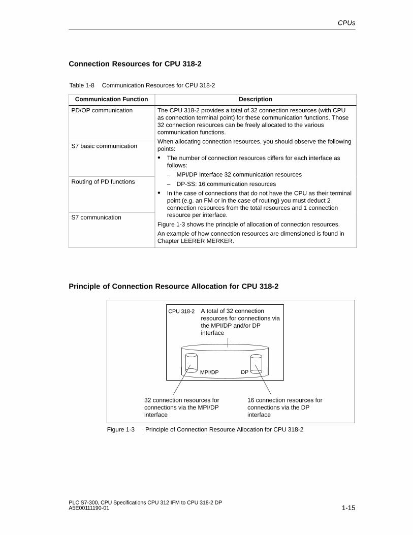
PD/OP communication The CPU 318-2 provides a total of 32 connection resources (with CPUas connection terminal point) for these communication functions. Those32 connection resources can be freely allocated to the variouscommunication functions.
S7 basic communicationWhen allocating connection resources, you should observe the followingpoints:
� The number of connection resources differs for each interface asfollows:
Routing of PD functions– MPI/DP Interface 32 communication resources
– DP-SS: 16 communication resources
� In the case of connections that do not have the CPU as their terminalpoint (e.g. an FM or in the case of routing) you must deduct 2connection resources from the total resources and 1 connection
S7 communication resource per interface.
Figure 1-3 shows the principle of allocation of connection resources.
An example of how connection resources are dimensioned is found inChapter LEERER MERKER.
Principle of Connection Resource Allocation for CPU 318-2
CPU 318-2
MPI/DP DP
32 connection resources forconnections via the MPI/DPinterface
16 connection resources forconnections via the DPinterface
A total of 32 connectionresources for connections viathe MPI/DP and/or DPinterface
Figure 1-3 Principle of Connection Resource Allocation for CPU 318-2

CPUs
1-16PLC S7-300, CPU Specifications CPU 312 IFM to CPU 318-2 DP
A5E00111190-01
Interface Resources for CPU 318-2 - Example Calculation
1. Two network transitions by routing on the CPU
Resources used:- 2 connection resources of the MPI/DP interface are used;- 2 connection resources of the DP interface are used;- all 4 connection resources available to both interfaces
are used;
2. 4 connections for S7 basic communication and PG/OP communication with theCPU as connection terminal point via MPI/DP interface
Resources used:- 4 connection resources of the MPI/DP interface are used;- all 4 connection resources available to both interfaces
are used;
Resources still availabe:- 26 connection resources of the MPI/DP interface;- 14 connection resources of the DP interface;- 24 of the connection resources available to both interfaces
Data Consistency for Communication
An essential aspect of the transmission of data between devices is its consistency.The data that is transmitted together should all originate from the same processingcycle and should thus belong together, i.e. be consistent.
If there is a programmed communication function such as X-SEND/ X-RCV whichaccesses shared data, then access to that data area can be co-ordinated bymeans of the parameter “BUSY” itself.
However, with S7 communication functions not requiring a block in the userprogram of the 31x CPU (as server), e.g. PUT/GET or read/write operations viaOP communication, the dimension of data consistency must be taken into accountduring programming. The following differences between CPUs 312IFM to 316-2 DPand CPU 318-2 must be taken into account:

CPUs
1-17PLC S7-300, CPU Specifications CPU 312 IFM to CPU 318-2 DPA5E00111190-01
CPU 312 IFM to 316-2 DP CPU 318-2
PUT/GET functions of S7 communication, orreading/writing variables via OPcommunication, are processed during the
PUT/GET functions of S7 communication, orreading/writing to variable via OPcommunication are processed in defined time
cycle checkpoint of the CPU.
A defined process interrupt reaction time isensured by consistent copying ofcommunication variables in blocks of 32 bytes(CPU Versions lower than described in this
windows in the CPU 318-2 operating system.For that reason, the user program can beinterrupted after every command(Byte/Word/Double Word command) when acommunication variable is being accessed.The data consistency of a communicationmanual: Blocks of up to 8 Bytes) into/out of
user memory during the cycle checkpoint ofthe operating system. Data consistency is notguaranteed for any larger data areas.
Therefore, communication variables in the
The data consistency of a communicationvariable is therefore only possible within thelimits of the command boundaries used in theuser program.
If a data consistency size greater than Byte,
user program must not exceed a length of 8or 32 byte if data consistency is required.
If you copy communication variables usingSFC 81 “UBLKMOV”, the copying process isnot interrupted by higher priority classes.
Word or DWord is required, communicationvariables in the user program must always becopied using SFC81 “UBLKMOV” thatguarantees consistent reading/writing of thecomplete communication variable area.

CPUs
1-18PLC S7-300, CPU Specifications CPU 312 IFM to CPU 318-2 DP
A5E00111190-01
Details
... on the communication topic are found in the STEP 7 Online Help and in themanual Communication with SIMATIC.
... on communications SFCs/SFBs are found in the STEP 7 Online Help and in theStandard and System functions reference manual.
Global Data Communication with S7-300 CPUs
Below you will find important features of global data communication in the S7-300.
Send/Receive Conditions
For the communication via GD circuits, you should observe the followingconditions:
� Required for the GD packet transmitter is:Reduction ratio Transmitter � Cycle time Transmitter � 60 ms (CPU 318-2: �10 ms
� Required for the GD packet receiver is:Reduction ratio Receiver � Cycle timer eceiver � Reduction ratio Transmitter � Cycletime Transmitter
Non-observance of these conditions can lead to the loss of a GD packet. Thereasons for this are:
� The performance capability of the smallest CPU in the GD circuit
� Sending and receiving of global data is carried out asynchronously by thesender and receiver.
Loss of global data is displayed in the status field of a GD circuit if you haveconfigured this with STEP 7.
Note
Note when communicating via global data: sent global data is not acknowledgedby the receiving partner!
The sender therefore receives no information on whether a receiver and whichreceiver has received the sent global data.
Send Cycles for Global Data
In STEP 7 (as of Version 3.0), the following situation can arise if you set “Sendafter every CPU cycle” with a short CPU cycle time (< 60 ms): the operatingsystem overwrites GD packets the CPU has not yet transmitted. Tip: Loss ofglobal data is displayed in the status field of a GD circuit if you have configured thiswith STEP 7.

CPUs
1-19PLC S7-300, CPU Specifications CPU 312 IFM to CPU 318-2 DPA5E00111190-01
1.3 Test Functions and Diagnostics
The CPUs provide you with:
� Testing functions for commissioning
� Diagnostics via LEDs and STEP 7.
1.3.1 Testing Functions
The CPUs offer you the following testing functions:
� Monitor Variables
� Modify Variables
� Forcing (note the differences between CPUs)
� Monitor block
� Set Breakpoint
Details on the testing functions are found in the STEP 7 Online Help.
Important for the Status FB!
The STEP 7 function “Status FB” increases CPU cycle time!
In STEP 7 you can specify a maximum permissible increase in cycle time (notCPU 318-2). In this case, in STEP 7 you must specify process mode for the CPUparameters.

CPUs
1-20PLC S7-300, CPU Specifications CPU 312 IFM to CPU 318-2 DP
A5E00111190-01
Different Features of Forcing S7-300
Please note the different features of forcing in the different CPUs:
CPU 318-2 CPU 312IFM to 316-2DP
The variables of a user program withfixed preset values (force values)cannot be changed or overwritten bythe user program.
It is not permissible to force peripheralor process image areas lying in therange of consistent user data.
The variables of a user program withfixed preset values (force values) canbe changed or overwritten in the userprogram.(See Figure 1-4 on page 1-21)
The following can be variables:
Inputs/outputsPeripheral I/OsMemory markers
You can force up to 256 variables.
The following can be variables:
Inputs/Outputs
You can force up to 10 variables.

CPUs
1-21PLC S7-300, CPU Specifications CPU 312 IFM to CPU 318-2 DPA5E00111190-01
Forcing with the CPU 312 IFM to 316-2 DP:
!Caution
Forced values in the input process image can be overwritten by write instructions(e.g. T EB x, = E x.y, copying with SFC etc.) and peripheral read instructions (e.g.L PEW x) in the user program, as well as by write instructions of PG/OP opera-tions!
Outputs initialized with forced values only return the forced value if the user pro-gram does not execute any write accesses to the outputs using peripheral writecommands (e.g. TPQB x ) and if no PG/OP functions write to these outputs!
Always note that forced values in the I/O process image cannot be overwritten bythe user program or PG/OP functions!
Execute forcejob for outputs
With S7-300 CPUs, forcing is the same as “cyclical modify”
PIItransfer User programOS
T PQW
Forced valueoverwritten by TPQW!
Execute forcejob for inputs
Forcedvalue
Execute forcejob for outputs
Forcedvalue
Execute forcejob for inputs
OS .... Operating system execution
PIOtransfer
PIItransfer
OSPIOtransfer
Figure 1-4 The Principle of Forcing with S7-300 CPUs (CPU 312IFM to 316-2DP)

CPUs
1-22PLC S7-300, CPU Specifications CPU 312 IFM to CPU 318-2 DP
A5E00111190-01
1.3.2 Diagnostics with LED Display
In Table 1-9, only the LEDs relevant to the diagnosis of the CPU and S7-300 arelisted. You will find the significance of the PROFIBUS-DP interface LEDs explainedin Chapter 2.
Table 1-9 Diagnostic LEDs of the CPU
LED Description
SF Comes on inthe event of
Hardware faultsProgramming errorsParameter assignment errorsCalculation errorsTiming errorsFaulty memory cardBattery fault or no backup at power onI/O fault/error (external I/O only)Communication error
BATF Comes onwhen
The backup battery is missing, faulty or not charged.Note Also lit if a rechargeable battery is installed. Reason:The user program is not backed up the rechargeable battery.
Stop Comes onwhen
Flashes when
The CPU is not processing a user program
The CPU requests a memory reset
1.3.3 Diagnostics with STEP 7
Note
Please note that this is not a fail-safe or redundant system, regardless of its exi-sting extensive monitoring and error reaction functions.
If an error occurs, the CPU enters the cause of the error in the diagnostic buffer.You can read the diagnostic buffer using the programming device.
The CPU switches to STOP if an error or interrupt event occurs, or your userprogram reacts accordingly with error or interrupt OBs. Details on STEP 7diagnostic functions are found in the STEP 7 Online Help.
In the Instruction list you can find an overview
� of the OBs you can use to react to respective error or interrupt events, as well
� as of the OBs you can program in the respective CPU

CPUs
1-23PLC S7-300, CPU Specifications CPU 312 IFM to CPU 318-2 DPA5E00111190-01
CPU Reaction on Missing Error OB
If you have not programmed an error OB, the CPU reacts as follows:
CPU goes into STOP on missing ... CPU Remains in RUN with Missing ...
OB 80 (Runtime error)
OB 85 (Program cycle error)
OB 86 (Station failure in the PROFIBUS-DP subnet)
OB 87 (Communication error)
OB 121 (Programming error)
OB 122 (Peripheral direct accesserror)
OB 81 (Power break)
CPU Behavior When There Is No Interrupt OB
If you have not programmed an interrupt OB, the CPU reacts as follows:
CPU goes into STOP on missing ... CPU Remains in RUN with Missing ...
OB 10/11 (TOD interrupt)
OB 20/21 (Delay interrupt)
OB 40/41 (Process interrupt)
OB 55 (TOD interrupt)
OB 56 (Delay interrupt)
OB 57 (for manufacturer-specificinterrupts)
OB 82 (Diagnostic interrupt)
OB 83 (Insertion/Removal interrupt)
OB 32/35 (Watchdog interrupt)
Tip on OB35 (CPU 318-2: also OB32)
For the watchdog interrupt OB 35/32, you can specify times starting from 1 ms.Note: The smaller the selected watchdog interrupt period, the more likelywatchdog interrupt errors will occur. You must take into account the operatingsystem times of the CPU in question, the runtime of the user program and theextension of the cycle by active programming device functions, for example.

CPUs
1-24PLC S7-300, CPU Specifications CPU 312 IFM to CPU 318-2 DP
A5E00111190-01
1.4 CPUs - Technical Specifications
In This Section
� You will find the technical specifications of the CPU.
� You will find the technical specifications of the integrated inputs/outputs of theCPU 312 IFM and 314 IFM.
� You will not find the features of the CPU 31x-2 DP as a DP master/DP slave.Refer to Chapter 2.
Section Contents Page
1.4.1 CPU 312 IFM 1-25
1.4.2 CPU 313 1-37
1.4.3 CPU 314 1-40
1.4.4 CPU 314 IFM 1-43
1.4.5 CPU 315 1-60
1.4.6 CPU 315-2 DP 1-63
1.4.7 CPU 316-2 DP 1-66
1.4.8 CPU 318-2 1-69

CPUs
1-25PLC S7-300, CPU Specifications CPU 312 IFM to CPU 318-2 DPA5E00111190-01
1.4.1 CPU 312 IFM
Special Features
� Integrated I/Os (Wiring via 20-pole front connector)
� No backup battery and therefore maintenance-free
� An S7-300 with CPU 312 IFM can be mounted only on one rack
Integrated Functions of the CPU 312 IFM
Integrated Functions Description
Process interrupt Interrupt input means: inputs configured with this function trigger a processinterrupt at the corresponding signal edge.
Interrupt input options for the digital inputs 124.6 to 125.1 must be programmedin STEP 7.
Counter The CPU 312 IFM offers these special functions as an alternative at the digitalinputs 124.6 to 125.1.
Frequency meter For a description of the special functions “Counter” and “Frequency meter”,please refer to the Integrated Functions Manual.
“Interrupt Inputs” of the CPU 312 IFM
If you wish to use the digital inputs 124.6 to 125.1 as interrupt inputs, you mustprogram these in STEP 7 in the CPU parameters.
Note the following points:
� These digital inputs have a very low signal delay. At this interrupt input, themodule recognizes pulses with a length as of approx. 10 to 50 �s. Always useshielded cable to connect active interrupt inputs in order to avoid interruptstriggered by line interference.Note The minimum pulse width of an interrupt trigger pulse is 50 �s.
� The input status associated with an interrupt in the input process image or withLPIB always changes with ”normal” input delay of approx.3 ms.
CPUs
1-26PLC S7-300, CPU Specifications CPU 312 IFM to CPU 318-2 DP
A5E00111190-01
Start information for OB40
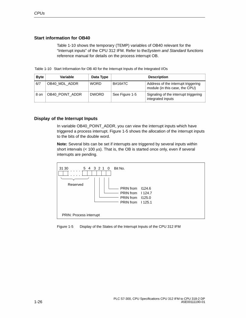
Table 1-10 shows the temporary (TEMP) variables of OB40 relevant for the“Interrupt inputs” of the CPU 312 IFM. Refer to theSystem and Standard functionsreference manual for details on the process interrupt OB.
Table 1-10 Start Information for OB 40 for the Interrupt Inputs of the Integrated I/Os
Byte Variable Data Type Description
6/7 OB40_MDL_ADDR WORD B#16#7C Address of the interrupt triggeringmodule (in this case, the CPU)
8 on OB40_POINT_ADDR DWORD See Figure 1-5 Signaling of the interrupt triggeringintegrated inputs
Display of the Interrupt Inputs
In variable OB40_POINT_ADDR, you can view the interrupt inputs which havetriggered a process interrupt. Figure 1-5 shows the allocation of the interrupt inputsto the bits of the double word.
Note: Several bits can be set if interrupts are triggered by several inputs withinshort intervals (< 100 �s). That is, the OB is started once only, even if severalinterrupts are pending.
0 Bit No.
PRIN from I124.6
5 4 13 231 30
PRIN from I 124.7PRIN from I125.0PRIN from I 125.1
Reserved
PRIN: Process interrupt
Figure 1-5 Display of the States of the Interrupt Inputs of the CPU 312 IFM

CPUs
1-27PLC S7-300, CPU Specifications CPU 312 IFM to CPU 318-2 DPA5E00111190-01
Front View
Status and fault LEDs
Mode selector
Multipoint Interface(MPI)
Front connector,used to connectthe integratedI/O, powersupply andsystem ground.
I124.0I 1I 2I 3I 4I 5I 6I 7I125.0
I 1Q124.0Q 1
Q 3Q 2
Q 4Q 5
Figure 1-6 Front View of the CPU 312 IFM

CPUs
1-28PLC S7-300, CPU Specifications CPU 312 IFM to CPU 318-2 DP
A5E00111190-01
Technical Specifications of the CPU 312 IFMCPU and Product Version
MLFB
� Hardware version
6ES7 312-5AC02-0AB0
01
� Firmware version V 1.1.0
� Matching programmingpackage
STEP 7 V 5.0;Service Pack 03
Memory
Work memory
� integral 6 KB
� Expandable no
Load memory
� integral 20 KB RAM20 KB EEPROM
� Expandable FEPROM no
� Expandable RAM no
Backup Yes
� With battery no
� Without battery 72 bytes retentiveConfigurable(data, flags, timers)
Processing times
Processing times for
� Bit instructions 0.6 �s minimum
� Word instructions 2 �s minimum
� Double integer math 3 �s minimum
� Floating-point mathinstructions
60 �s minimum
Timers/Counters and their retentive characteristics
S7 counters 32
� Adjustable retentivity from C 0 to C 31
� Preset from C 0 to C 7
� Counting range 1 to 999
IEC Counters Yes
� Type SFBs
S7 timers 64
� Adjustable retentivity No
� Timing range 10 ms to 9990 s
IEC Timers Yes
� Type SFBs
Data areas and their retentive characteristics
Retentive data area as awhole (inc. flags, timers,counters)
max. 1 DB, 72 data bytes
Bit memories 1024
� Adjustable retentivity MB 0 to MB 71
� Preset MB 0 to MB 15
Clock memories 8 (1 memory byte)
Data blocks max. 63 (DB 0 reserved)
� Size max. 6 KB
� Adjustable retentivity max. 1 DB, 72 bytes
� Preset No retentivity
Local data (non-alterable) max. 512 bytes
� Per priority class 256 bytes
Blocks
OBs See Instruction List
� Size max. 6 KB
Nesting depth
� Per priority class 8
� additional levels withinan error OB
None
FBs max. 32;
� Size max. 6 KB
FCs max. 32;
� Size max. 6 KB
Address areas (I/O)
Peripheral address area
� Digital
– integrated
0 to 31/0 to 31
124,125 E/124 A
� Analog 256 to 383/256 to 383
Process image (cannot becustomized)
32 bytes+4 bytesintegrated/ 32 bytes+4bytes integrated
Digital channels 256+10 integrated/256+6integrated
Analog channels 64/32

CPUs
1-29PLC S7-300, CPU Specifications CPU 312 IFM to CPU 318-2 DPA5E00111190-01
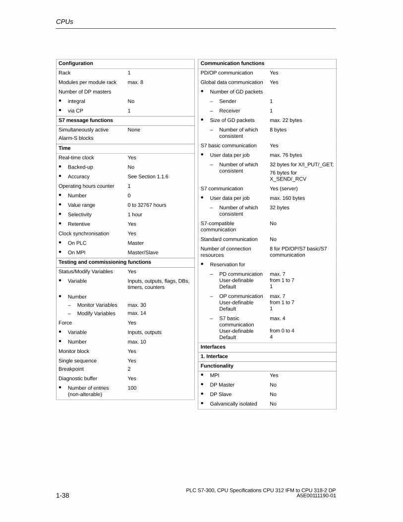
Configuration
Rack 1
Modules per module rack max. 8
DP Master
� integral None
� via CP Yes
S7 message functions
Simultaneously active
Alarm-S blocks
None
Time
Real-time clock Yes
� Backed-up No
� Accuracy See Section 1.1.6
Operating hours counter No
Clock synchronisation Yes
� On PLC Master
� On MPI Master/Slave
Testing and commissioning functions
Status/Modify Variables Yes
� Variable Inputs, outputs, flags, DBs,timers, counters
� Number
– Monitor Variables
– Modify Variables
max. 30
max. 14
Force Yes
� Variable Inputs, outputs
� Number max. 10
Monitor block Yes
Single sequence
Breakpoint
Yes
2
Diagnostic buffer Yes
� Number of entries(non-alterable)
100
Communication functions
PD/OP communication Yes
Global data communication Yes
� Number of GD packets
– Sender 1
– Receiver 1
� Size of GD packets max. 22 bytes
– Number of whichconsistent
8 bytes
S7 basic communication Yes
� User data per job max. 76 bytes
– Number of whichconsistent
32 bytes for X/I_PUT/_GET;
76 bytes forX_SEND/_RCV
S7 communication Yes (server)
� User data per job max. 160 bytes
– Number of whichconsistent
32 bytes
S7-compatiblecommunication
No
Standard communication No
Number of connectionresources
6 for PD/OP/S7 basic/S7communication
� Reservation for
– PD communicationUser-definableDefault
max. 5from 1 to 51
– OP communicationUser-definableDefault
max. 5from 1 to 51
– S7 basiccommunication User-definableDefault
max. 2
from 0 to 22
Interfaces
1. Interface
Functionality
� MPI Yes
� DP Master No
� DP Slave No
� Galvanically isolated No

CPUs
1-30PLC S7-300, CPU Specifications CPU 312 IFM to CPU 318-2 DP
A5E00111190-01
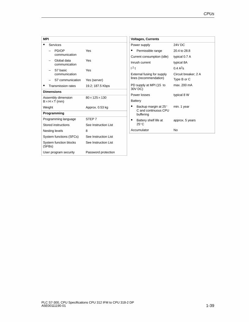
MPI
� Services
– PD/OPcommunication
Yes
– Global datacommunication
Yes
– S7 basiccommunication
Yes
– S7 communication Yes (server)
� Transmission rates 19.2; 187.5 Kbps
Dimensions
Assembly dimensionB�H�T (mm)
80�125�130
Weight Approx. 0.45 kg
Programming
Programming language STEP 7
Stored instructions See Instruction List
Nesting levels 8
System functions (SFCs) See Instruction List
System function blocks(SFBs)
See Instruction List
User program security Password protection
Voltages, Currents
Power supply 24V DC
� Permissible range 20.4 to 28.8 V
Current consumption (idle) typical 0.7 A
Inrush current typical 8A
l 2 t 0.4 A2s
External fusing for supplylines (recommendation)
Circuit breaker; 10 A,
Type B or C
PG supply on MPI (15 to30V DC)
max. 200 mA
Power losses typical 9 W
Battery No
Accumulator No
Integrated inputs/outputs
Addresses of integral
� Digital inputs E 124.0 to E 127.7
� Digital outputs A 124.0 to A 124.7
Integrated Functions
Counter 1 (see IntegratedFunctions)
manual
Frequency meter up to 10 kHz max.
(see Integrated Functions)
manual

CPUs
1-31PLC S7-300, CPU Specifications CPU 312 IFM to CPU 318-2 DPA5E00111190-01
Technical Specifications of the Special Inputs of the CPU 312IFM
Module-Specific Data
Number of inputs 4I 124.6 to 125.1
Cable length
� Shielded max. 100 m (109yd.)
Voltages, Currents, Potentials
Number of inputs that canbe triggered simultaneously
� (horizontalconfiguration)
up to 60°C� (vertical configuration)
up to 40°C
4
4
4
Status, Interrupts; Diagnostics
Status display 1 green LED perchannel
Interrupts
� Process interrupt Configurable
Diagnostic functions None
Sensor Selection Data
Input voltage
� Rated value
� For “1” signalI 125.0 and I 125.1I 124.6 and I 124.7
� For “0” signal
24V DC
15 to 30 V15 to 30 V
-3 to 5 V
Input current
� For “1” signalI 125.0 and I 125.1I 124.6 and I 124.7
min. 2 mAmin. 6.5 mA
Input delay time
� For “0” to “1”
� For “1” to “0”
max. 50 �s
max. 50 �s
Input characteristic
E 125.0 and E 125.1
E 124.6 and 124.7
to IEC 1131, Type 1to IEC 1131, Type 1
Connection of 2-wireBEROs
� Permissible idle currentI 125.0 and I 125.1I 124.6 and I 124.7
no
max. 0.5 mAmax. 2 mA
Time, Frequency
Internal conditioning timefor
� Interrupt processing
max. 1.5 ms
Input frequency � 10 kHz

CPUs
1-32PLC S7-300, CPU Specifications CPU 312 IFM to CPU 318-2 DP
A5E00111190-01
Technical Specifications of the Digital Inputs of the CPU 312IFM
Note
Alternatively, you can configure the inputs I 124.6 and I 124.7 as special inputs, inwhich case the technical specifications listed for the special inputs apply to theinputs I 124.6 and I 124.7.
Module-Specific Data
Number of inputs 8
Cable length
� Unshielded
� Shielded
max. 600 m
max. 1000 m
Voltages, Currents, Potentials
Number of inputs that canbe triggered simultaneously
� (horizontalconfiguration)
up to 60°C� (vertical configuration)
up to 40°C
8
8
8
Galvanic isolation No
Status, Interrupts; Diagnostics
Status display 1 green LED perchannel
Interrupts None
Diagnostic functions None
Sensor Selection Data
Input voltage
� Rated value
� For “1” signal
� For “0” signal
24V DC
11 to 30 V
-3 to 5 V
Input current
� For “1” signal typical 7 mA
Input delay time
� For “0” to “1”
� For “1” to “0”
1.2 to 4.8 ms
1.2 to 4.8 ms
Input characteristic to IEC 1131, Type 2
Connection of 2-wireBEROs
� Permissible quiescentcurrent
Possible
max. 2 mA

CPUs
1-33PLC S7-300, CPU Specifications CPU 312 IFM to CPU 318-2 DPA5E00111190-01
Technical Specifications of the Digital Outputs of the CPU 312IFM
Module-Specific Data
Number of outputs 6
Cable length
� Unshielded
� Shielded
max. 600 m
max. 1000 m
Voltages, Currents, Potentials
Total current of outputs (pergroup)
� (horizontalconfiguration)
up to 40°Cup to 60°C
� (vertical configuration)
up to 40°C
max. 3 A
max. 3 A
max. 3 A
Galvanic isolation No
Status, Interrupts; Diagnostics
Status display 1 green LED perchannel
Interrupts None
Diagnostic functions None
Actuator Selection Data
Output voltage
� For “1” signal min. L+ (-0.8 V)
Output current
� For “1” signal
Rated value
Permissible range
� For “0” signal Residual current
0.5 A
5 mA to 0.6 A
max. 0.5 mA
Load impedance range 48 � to 4 k�
Lamp load max. 5 W
Parallel connection of 2outputs
� For dual-channeltriggering of a load
� For performanceincrease
Possible
Not possible
Triggering of a digital input Possible
Switching frequency
� For resistive load
� For inductive load toIEC947-5-1, DC 13
� For lamp load
max. 100 Hz
max. 0.5 Hz
max. 100 Hz
Inductive breaking voltagelimited internally to
typical V 30
Short-circuit protection ofthe output
� Response threshold
yes, electronicallytimed
typical 1 A

CPUs
1-34PLC S7-300, CPU Specifications CPU 312 IFM to CPU 318-2 DP
A5E00111190-01
Wiring diagram of the CPU 312 IFM
Figure 1-7 shows the wiring diagram of the CPU 312 IFM. Use a 20-pole frontconnector to wire the CPU’s integrated I/O.
!Caution
The CPU 312 IFM has no reverse polarity protection. Polarity reversal destroysthe integrated outputs. Nonetheless, in this case the CPU does not switch toSTOP and the status displays are lit. In other words, the fault is not indicated.
I124.0I 1I 2I 3I 4I 5I 6I 7I125.0
I 1Q124.0Q 1
Q 3Q 2
Q 4Q 5
Figure 1-7 Wiring diagram of the CPU 312 IFM
Grounded Configuration Only
You can use the CPU 312 IFM in a grounded configuration only. In the CPU 312IGFM, system ground is connected internally to chassis ground (M) (seeFigure 1-8, page 1-36).

CPUs
1-35PLC S7-300, CPU Specifications CPU 312 IFM to CPU 318-2 DPA5E00111190-01
Power Supply Connections
The
� CPU 312 IFM and
� the integrated I/Os
are connected to power at the terminals 18 and 19 (see Figure 1-7).
Short-circuit reaction
On short-circuit at one of the integrated outputs of CPU 312 IFM, proceed asfollows:
1. Switch the CPU 312 IFM to STOP or switch off the power supply.
2. Eliminate the cause of the short-circuit.
3. Switch the CPU 312 IFM back to RUN or switch the power supply back on.

CPUs
1-36PLC S7-300, CPU Specifications CPU 312 IFM to CPU 318-2 DP
A5E00111190-01
Basic Circuit Diagram of the CPU 312 IFM
Figure 1-8 shows the block diagram of CPU 312 IFM.
CPU
CPU powersupply
M
L +
M
Figure 1-8 Basic Circuit Diagram of the CPU 312 IFM

CPUs
1-37PLC S7-300, CPU Specifications CPU 312 IFM to CPU 318-2 DPA5E00111190-01
1.4.2 CPU 313
Technical Specifications of the CPU 313CPU and Product Version
MLFB
� Hardware version
6ES7 313-1AD03-0AB0
01
� Firmware version V 1.1.0
� Matching programmingpackage
STEP 7 V 5.0;Service Pack 03
Memory
Work memory
� integral 12 KB
� Expandable no
Load memory
� integral 20 KB RAM
� Expandable FEPROM Up to 4 MB
� Expandable RAM no
Backup Yes
� With battery All data
� Without battery 72 bytes retentiveConfigurable(data, flags, timers)
Processing times
Processing times for
� Bit instructions 0.6 �s minimum
� Word instructions 2 �s minimum
� Double integer math 2 �s minimum
� Floating-point mathinstructions
60 �s minimum
Timers/Counters and their retentive characteristics
S7 counters 64
� Adjustable retentivity from C 0 to C 63
� Preset from C 0 to C 7
� Counting range 1 to 999
IEC Counters Yes
� Type SFB
S7 timers 128
� Adjustable retentivity from T 0 to T 31
� Preset No retentive times
� Timing range 10 ms to 9990 s
IEC Timers Yes
� Type SFB
Data areas and their retentive characteristics
Retentive data area as awhole (inc. flags, timers,counters)
max. 1 DB, 72 data bytes
Bit memories 2048
� Adjustable retentivity MB 0 to MB 71
� Preset MB 0 to MB 15
Clock memories 8 (1 memory byte)
Data blocks max. 127 (DB 0 reserved)
� Size max. 8 KB
� Adjustable retentivity 1 DB, 72 bytes
� Preset No retentivity
Local data (non-alterable) max. 1536 bytes
� Per priority class 256 bytes
Blocks
OBs See Instruction List
� Size max. 8 KB
Nesting depth
� Per priority class 8
� additional levels withinan error OB
4
FBs 128
� Size max. 8 KB
FCs 128
� Size max. 8 KB
Address areas (I/O)
Peripheral address area
� Digital 0 to 31/0 to 31
� Analog 256 to 383/256 to 383
Process image (cannot becustomized)
32 bytes/32 bytes
Digital channels max. 256/256
Analog channels max. 64/32
CPUs
1-38PLC S7-300, CPU Specifications CPU 312 IFM to CPU 318-2 DP
A5E00111190-01
Configuration
Rack 1
Modules per module rack max. 8
Number of DP masters
� integral No
� via CP 1
S7 message functions
Simultaneously active
Alarm-S blocks
None
Time
Real-time clock Yes
� Backed-up No
� Accuracy See Section 1.1.6
Operating hours counter 1
� Number 0
� Value range 0 to 32767 hours
� Selectivity 1 hour
� Retentive Yes
Clock synchronisation Yes
� On PLC Master
� On MPI Master/Slave
Testing and commissioning functions
Status/Modify Variables Yes
� Variable Inputs, outputs, flags, DBs,timers, counters
� Number
– Monitor Variables
– Modify Variables
max. 30
max. 14
Force Yes
� Variable Inputs, outputs
� Number max. 10
Monitor block Yes
Single sequence
Breakpoint
Yes
2
Diagnostic buffer Yes
� Number of entries(non-alterable)
100
Communication functions
PD/OP communication Yes
Global data communication Yes
� Number of GD packets
– Sender 1
– Receiver 1
� Size of GD packets max. 22 bytes
– Number of whichconsistent
8 bytes
S7 basic communication Yes
� User data per job max. 76 bytes
– Number of whichconsistent
32 bytes for X/I_PUT/_GET;
76 bytes forX_SEND/_RCV
S7 communication Yes (server)
� User data per job max. 160 bytes
– Number of whichconsistent
32 bytes
S7-compatiblecommunication
No
Standard communication No
Number of connectionresources
8 for PD/OP/S7 basic/S7communication
� Reservation for
– PD communicationUser-definableDefault
max. 7from 1 to 71
– OP communicationUser-definableDefault
max. 7from 1 to 71
– S7 basiccommunication User-definableDefault
max. 4
from 0 to 44
Interfaces
1. Interface
Functionality
� MPI Yes
� DP Master No
� DP Slave No
� Galvanically isolated No
CPUs
1-39PLC S7-300, CPU Specifications CPU 312 IFM to CPU 318-2 DPA5E00111190-01
MPI
� Services
– PD/OPcommunication
Yes
– Global datacommunication
Yes
– S7 basiccommunication
Yes
– S7 communication Yes (server)
� Transmission rates 19.2; 187.5 Kbps
Dimensions
Assembly dimensionB�H�T (mm)
80�125�130
Weight Approx. 0.53 kg
Programming
Programming language STEP 7
Stored instructions See Instruction List
Nesting levels 8
System functions (SFCs) See Instruction List
System function blocks(SFBs)
See Instruction List
User program security Password protection
Voltages, Currents
Power supply 24V DC
� Permissible range 20.4 to 28.8
Current consumption (idle) typical 0.7 A
Inrush current typical 8A
l 2 t 0.4 A2s
External fusing for supplylines (recommendation)
Circuit breaker; 2 A
Type B or C
PD supply at MPI (15 to30V DC)
max. 200 mA
Power losses typical 8 W
Battery
� Backup margin at 25�C and continuous CPUbuffering
min. 1 year
� Battery shelf life at25�C
approx. 5 years
Accumulator No

CPUs
1-40PLC S7-300, CPU Specifications CPU 312 IFM to CPU 318-2 DP
A5E00111190-01
1.4.3 CPU 314
Technical Specifications of the CPU 314CPU and Product Version
MLFB
� Hardware version
6ES7 314-1AE04-0AB0
01
� Firmware version V 1.1.0
� Matching programmingpackage
STEP 7 V 5.0;Service Pack 03
Memory
Work memory
� integral 24 KB
� Expandable no
Load memory
� integral 40 KB RAM
� Expandable FEPROM Up to 4 MB
� Expandable RAM no
Backup Yes
� With battery All data
� Without battery 4736 bytes, configurable,(data, flags, timers)
Processing times
Processing times for
� Bit instructions 0.3 �s minimum
� Word instructions 1 �s minimum
� Double integer math 2 �s minimum
� Floating-point mathinstructions
50 �s minimum
Timers/Counters and their retentive characteristics
S7 counters 64
� Adjustable retentivity from C 0 to C 63
� Preset from C 0 to C 7
� Counting range 0 to 999
IEC Counters Yes
� Type SFB
S7 timers 128
� Adjustable retentivity from T 0 to T 127
� Preset No retentive times
� Timing range 10 ms to 9990 s
IEC Timers Yes
� Type SFB
Data areas and their retentive characteristics
Retentive data area as awhole (inc. flags, timers,counters)
4736 bytes
Bit memories 2048
� Adjustable retentivity MB 0 to MB 255
� Preset MB 0 to MB 15
Clock memories 8 (1 memory byte)
Data blocks max. 127 (DB 0 reserved)
� Size max. 8 KB
� Adjustable retentivity max. 8 DB, 4096 data bytesin all
� Preset No retentivity
Local data (non-alterable) max. 1536 bytes
� Per priority class 256 bytes
Blocks
OBs See Instruction List
� Size max. 8 KB
Nesting depth
� Per priority class 8
� additional levels withinan error OB
4
FBs max. 128
� Size max. 8 KB
FCs max. 128
� Size max. 8 KB
Address areas (I/O)
Peripheral address area
� Digital 0 to 127/0 to 127
� Analog 256 to 767/256 to 767
Process image (cannot becustomized)
128 bytes/128 bytes
Digital channels max. 1024/1024
Analog channels max. 256/128

CPUs
1-41PLC S7-300, CPU Specifications CPU 312 IFM to CPU 318-2 DPA5E00111190-01
Configuration
Rack max. 4
Modules per module rack max. 8
Number of DP masters
� integral None
� via CP 1
S7 message functions
Simultaneously active
Alarm-S blocks
max. 40
Time
Real-time clock Yes
� Backed-up Yes
� Accuracy See Section 1.1.6
Operating hours counter 1
� Number 0
� Value range 0 to 32767 hours
� Selectivity 1 hour
� Retentive Yes
Clock synchronisation Yes
� On PLC Master
� On MPI Master/Slave
Testing and commissioning functions
Status/Modify Variables Yes
� Variable Inputs, outputs, flags, DBs,timers, counters
� Number
– Monitor Variables
– Modify Variables
max. 30
max. 14
Force Yes
� Variable Inputs, outputs
� Number max. 10
Monitor block Yes
Single sequence
Breakpoint
Yes
2
Diagnostic buffer Yes
� Number of entries(non-alterable)
100
Communication functions
PD/OP communication Yes
Global data communication Yes
� Number of GD packets
– Sender 1
– Receiver 1
� Size of GD packets max. 22 bytes
– Number of whichconsistent
8 bytes
S7 basic communication Yes
� User data per job max. 76 bytes
– Number of whichconsistent
32 bytes for X/I_PUT/_GET;
76 bytes forX_SEND/_RCV
S7 communication Yes (server)
� User data per job max. 160 bytes
– Number of whichconsistent
32 bytes
S7-compatiblecommunication
Yes (via CP and loadableFC)
� User data per job Dependent on CP
– Number of whichconsistent
Dependent on CP
Standard communication Yes (via CP and loadableFC)
� User data per job Dependent on CP
– Number of whichconsistent
Dependent on CP
Number of connectionresources
12 for PD/OP/S7 basic/S7communication
� Reservation for
– PD communicationUser-definableDefault
max. 11from 1 to 111
– OP communicationUser-definableDefault
max. 11from 1 to 111
– S7 basiccommunication User-definableDefault
max. 8
from 0 to 88
Interfaces
1. Interface
Functionality
� MPI Yes
� DP Master No
� DP Slave No
� Galvanically isolated No

CPUs
1-42PLC S7-300, CPU Specifications CPU 312 IFM to CPU 318-2 DP
A5E00111190-01
MPI
� Services
– PD/OPcommunication
Yes
– Global datacommunication
Yes
– S7 basiccommunication
Yes
– S7 communication Yes (server)
� Transmission rates 19.2; 187.5 Kbps
Dimensions
Assembly dimensionB�H�T (mm)
80�125�130
Weight Approx. 0.53 kg
Programming
Programming language STEP 7
Stored instructions See Instruction List
Nesting levels 8
System functions (SFCs) See Instruction List
System function blocks(SFBs)
See Instruction List
User program security Password protection
Voltages, Currents
Power supply 24V DC
� Permissible range 20.4 V to 28.8 V
Current consumption (idle) typical 0.7 A
Inrush current typical 8A
l 2 t 0.4 A2s
External fusing for supplylines (recommendation)
Circuit breaker; 2 A,
Type B or C
PD supply at MPI (15 to30V DC)
max. 200 mA
Power losses typical 8 W
Battery Yes
� Backup margin at 25�C and continuous CPUbuffering
min. 1 year
� Battery shelf life at25�C
approx. 5 years
Accumulator Yes
� Clock back-up period
– at 0 to 25�C Approx. 4 weeks
– at 40� C Approx. 3 weeks
– at 60 � C Approx. 1 week
� Battery charging time Approx. 1 hour

CPUs
1-43PLC S7-300, CPU Specifications CPU 312 IFM to CPU 318-2 DPA5E00111190-01
1.4.4 CPU 314IFM
Special Features
� Integrated I/Os (wired with 40-pole front connector)
Details on analog value processing and how to connect measuring transducers,load and actuators to analog I/O is found in the Module Data reference manual.Figures 1-14 and 1-15 on page 1-59 show wiring examples.
Memory card
The CPU 314 IFM is available in 2 versions: with and without Memory Card slot.
� With slot for memory card: 6ES7 314-5AE10-0AB0
� Without slot for memory card: 6ES7 314-5AE0x-0AB0
Integrated Functions of the CPU 314 IFM
IntegratedFunctions
Description
Process interrupt Interrupt input means: inputs configured with this function trigger a processinterrupt at the corresponding signal edge.
If you wish to use the digital inputs 126.0 to 126.3 as interrupt inputs, you mustprogram these using STEP 7.
Note: Your user program should access analog inputs of your CPUindividually per L PEW in order to avoid an increase of interruptresponse times. Double-word addressing can increase the accesstimes by up to 200 �s!
Counter The CPU 314 IFM offers these special functions as an alternative at the
Frequency meter digital inputs 126.0 to 126.3. For a description of these special
Counter A/Bfunctions, please refer to the Integrated Functions Manual.
Positioning
CONT_C These functions are not restricted to specific inputs and outputs of the
CONT_S CPU 314 IFM. For a description of these functions, please refer to the
PULSEGENSystem and Standard Functions Reference Manual.

CPUs
1-44PLC S7-300, CPU Specifications CPU 312 IFM to CPU 318-2 DP
A5E00111190-01
“Interrupt Inputs” of the CPU 314 IFM
If you want to assign interrupt functions to the digital inputs 126.0 to 126.4,configure your CPU parameters in STEP 7 accordingly.
Note the following points:
These digital inputs have a very low signal delay. At this interrupt input, the modulerecognizes pulses with a length as of approx. 10 to 50 �s. Always use shieldedcable to connect active interrupt inputs in order to avoid interrupts triggered by lineinterference.
Note The minimum pulse width of an interrupt trigger pulse is 50 �s.
Start information for OB40
Table 1-10 shows the temporary (TEMP) variables of OB40 relevant for the“Interrupt inputs” of the CPU 314 IFM. Refer to theSystem and Standard functionsreference manual for details on the process interrupt OB.
Table 1-11 Start Information for OB 40 for the Interrupt Inputs of the Integrated I/Os
Byte Variable Data Type Description
6/7 OB40_MDL_ADDR WORD B#16#7C Address of the interrupt triggeringmodule (in this case, the CPU)
8 on OB40_POINT_ADDR DWORD See Figure 1-9 Signaling of the interrupt triggeringintegrated inputs

CPUs
1-45PLC S7-300, CPU Specifications CPU 312 IFM to CPU 318-2 DPA5E00111190-01
Display of the Interrupt Inputs
In variable OB40_POINT_ADDR, you can view the interrupt inputs which havetriggered a process interrupt. Figure 1-9 shows the allocation of the interrupt inputsto the bits of the double word.
Note: Several bits can be set if interrupts are triggered by several inputs withinshort intervals (< 100 �s). That is, the OB is started once only, even if severalinterrupts are pending.
0 Bit No.
PRIN from I126.0
5 4 13 231 30
PRIN from I126.1PRIN from I 126.2PRIN from I126.3
Reserved
PRIN: Processinterrupt
Figure 1-9 Display of the States of the Interrupt Inputs of the CPU 314 IFM

CPUs
1-46PLC S7-300, CPU Specifications CPU 312 IFM to CPU 318-2 DP
A5E00111190-01
Front View of the CPU 314 IFM
IN OUTOUT
ML+M
�
�
�
�
� �
� Status and error LEDs� Mode selector switch� Compartment for backup battery or rechargeable battery� Jumper (removable)
�
� Connection for power supply and system ground
� Multipoint interface MPI� Integrated I/Os
�
Memory Card slot (only -5AE10-)
Figure 1-10 Front View of the CPU 314 IFM
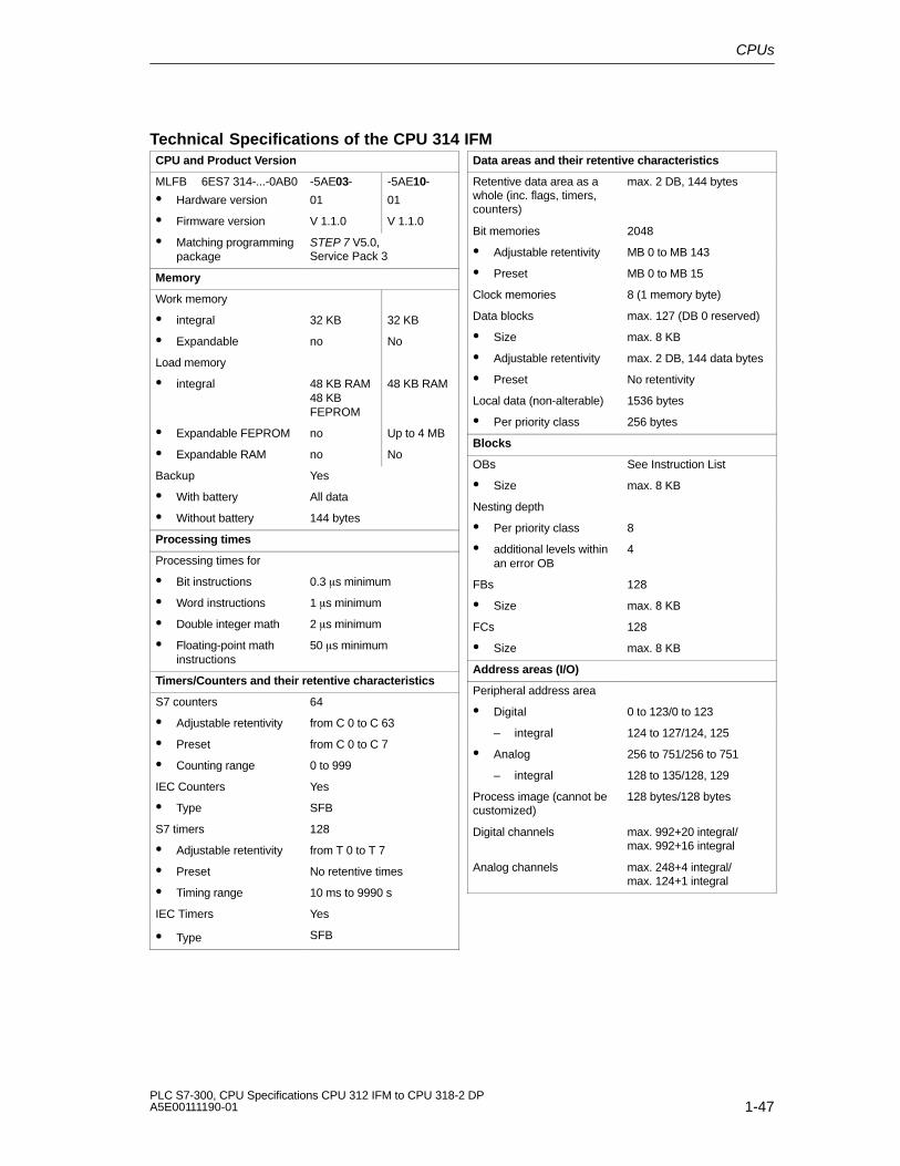
CPUs
1-47PLC S7-300, CPU Specifications CPU 312 IFM to CPU 318-2 DPA5E00111190-01
Technical Specifications of the CPU 314 IFMCPU and Product Version
MLFB 6ES7 314-...-0AB0
� Hardware version
-5AE03-
01
-5AE10-
01
� Firmware version V 1.1.0 V 1.1.0
� Matching programmingpackage
STEP 7 V5.0,Service Pack 3
Memory
Work memory
� integral 32 KB 32 KB
� Expandable no No
Load memory
� integral 48 KB RAM48 KBFEPROM
48 KB RAM
� Expandable FEPROM no Up to 4 MB
� Expandable RAM no No
Backup Yes
� With battery All data
� Without battery 144 bytes
Processing times
Processing times for
� Bit instructions 0.3 �s minimum
� Word instructions 1 �s minimum
� Double integer math 2 �s minimum
� Floating-point mathinstructions
50 �s minimum
Timers/Counters and their retentive characteristics
S7 counters 64
� Adjustable retentivity from C 0 to C 63
� Preset from C 0 to C 7
� Counting range 0 to 999
IEC Counters Yes
� Type SFB
S7 timers 128
� Adjustable retentivity from T 0 to T 7
� Preset No retentive times
� Timing range 10 ms to 9990 s
IEC Timers Yes
� Type SFB
Data areas and their retentive characteristics
Retentive data area as awhole (inc. flags, timers,counters)
max. 2 DB, 144 bytes
Bit memories 2048
� Adjustable retentivity MB 0 to MB 143
� Preset MB 0 to MB 15
Clock memories 8 (1 memory byte)
Data blocks max. 127 (DB 0 reserved)
� Size max. 8 KB
� Adjustable retentivity max. 2 DB, 144 data bytes
� Preset No retentivity
Local data (non-alterable) 1536 bytes
� Per priority class 256 bytes
Blocks
OBs See Instruction List
� Size max. 8 KB
Nesting depth
� Per priority class 8
� additional levels withinan error OB
4
FBs 128
� Size max. 8 KB
FCs 128
� Size max. 8 KB
Address areas (I/O)
Peripheral address area
� Digital 0 to 123/0 to 123
– integral 124 to 127/124, 125
� Analog 256 to 751/256 to 751
– integral 128 to 135/128, 129
Process image (cannot becustomized)
128 bytes/128 bytes
Digital channels max. 992+20 integral/max. 992+16 integral
Analog channels max. 248+4 integral/max. 124+1 integral

CPUs
1-48PLC S7-300, CPU Specifications CPU 312 IFM to CPU 318-2 DP
A5E00111190-01
Configuration
Rack max. 4
Modules per module rack max. 8; max. 7 in modulerack 3
Number of DP masters
� integral None
� via CP 1
S7 message functions
Simultaneously active
Alarm-S blocks
max. 40
Time
Real-time clock Yes
� Backed-up Yes
� Accuracy See Section 1.1.6
Operating hours counter 1
� Number 0
� Value range 0 to 32767 hours
� Selectivity 1 hour
� Retentive Yes
Clock synchronisation Yes
� On PLC Master
� On MPI Master/Slave
Testing and commissioning functions
Status/Modify Variables Yes
� Variable Inputs, outputs, flags, DBs,timers, counters
� Number
– Monitor Variables
– Modify Variables
max. 30
max. 14
Force Yes
� Variable Inputs, outputs
� Number max. 10
Monitor block Yes
Single sequence
Breakpoint
Yes
2
Diagnostic buffer Yes
� Number of entries(non-alterable)
100
Communication functions
PD/OP communication Yes
Global data communication Yes
� Number of GD packets
– Sender 1
– Receiver 1
� Size of GD packets max. 22 bytes
– Number of whichconsistent
8 bytes
S7 basic communication Yes
� User data per job max. 76 bytes
– Number of whichconsistent
32 bytes for X/I_PUT/_GET;
76 bytes forX_SEND/_RCV
S7 communication Yes (server)
� User data per job max. 160 bytes
– Number of whichconsistent
32 bytes
S7-compatiblecommunication
Yes (via CP and loadableFC)
� User data per job Dependent on CP
– Number of whichconsistent
Dependent on CP
Standard communication Yes (via FC and loadableFC)
� User data per job Dependent on CP
– Number of whichconsistent
Dependent on CP
Number of connectionresources
12 for PD/OP/S7 basic/S7communication
� Reservation for
– PD communicationUser-definableDefault
max. 11from 1 to 111
– OP communicationUser-definableDefault
max. 11from 1 to 111
– S7 basiccommunication User-definableDefault
max. 8
from 0 to 88
Interfaces
1. Interface
Functionality
� MPI Yes
� DP Master No
� DP Slave No
� Galvanically isolated No

CPUs
1-49PLC S7-300, CPU Specifications CPU 312 IFM to CPU 318-2 DPA5E00111190-01
MPI
� Services
– PD/OPcommunication
Yes
– Global datacommunication
Yes
– S7 basiccommunication
Yes
– S7 communication Yes (server)
� Transmission rates 19.2; 187.5 Kbps
Dimensions
Assembly dimensionB�H�T (mm)
160�125�130
Weight Approx. 0.9 kg
Programming
Programming language STEP 7
Stored instructions See Instruction List
Nesting levels 8
System functions (SFCs) See Instruction List
System function blocks(SFBs)
See Instruction List
User program security Password protection
Voltages, Currents
Power supply 24V DC
� Permissible range 20.4 to 28.8 V
Current consumption (idle) typical 1.0 A
Inrush current typical 8A
l 2 t 0.4 A2s
External fusing for supplylines (recommendation)
Circuit breaker; 2 A
Type B or C
PD supply at MPI (15 to30V DC)
max. 200 mA
Power losses Typically 16 W
Battery Yes
� Backup margin at 25�C and continuous CPUbuffering
min. 1 year
� Battery shelf life at25�C
approx. 5 years
Accumulator Yes
� Clock back-up period
– at 0 to 25�C Approx. 4 weeks
– at 40� C Approx. 3 weeks
– at 60 � C Approx. 1 week
� Battery charging time Approx. 1 hour
Integrated inputs/outputs
Addresses of integral
� Digital inputs E 124.0 to E 127.7
� Digital outputs A 124.0 to A 127.7
� Analog inputs PIW 128 to PIW 134
� Analog outputs PQW 128
Integrated Functions
Counter 1 or 2, 2 directionalcomparisons
(see Integrated Functions)
manual
Frequency meter up to 10 kHz max.
(see Integrated Functions)
manual
Positioning Channel 1
(see Integrated Functions)
manual

CPUs
1-50PLC S7-300, CPU Specifications CPU 312 IFM to CPU 318-2 DP
A5E00111190-01
Characteristic Features of the Integrated Inputs and Outputs of the CPU 314 IFM
Table 1-12 Characteristic Features of the Integrated Inputs and Outputs of the CPU 314 IFM
Inputs/Outputs Characteristics
Analog inputs � Voltage inputs ��10 V
� Current inputs ��20 mA
� Resolution 11 bits + sign bit
� Galvanically isolated
All information required for
� analog value display, as well asfor
� connecting measuring
Analog output � Voltage output ��10 V
� Current output ��20 mA
� Resolution 11 bits + sign bit
� Galvanically isolated
transducers, loads and actuatorsto the analog I/Os
can be found in the ModuleSpecifications Reference Manual.
Digital inputs Special inputs (E 126.0 to E 126.3) “Standard” Inputs
� Input frequency up to 10 kHz
� Non-isolated
� Galvanically isolated
� Rated input voltage 24V DC
� Suitable for switch and 2-wire proximity switches (BEROs)
Digital outputs � Output current 0.5 A
� Rated load voltage 24V DC
� Galvanically isolated
� Suitable for solenoid valves and DC contactors

CPUs
1-51PLC S7-300, CPU Specifications CPU 312 IFM to CPU 318-2 DPA5E00111190-01
Technical Specifications of the Analog Inputs of the CPU 314IFM
Module-Specific Data
Number of inputs 4
Cable length
� Shielded max. 100 m (109yd.)
Voltages, Currents, Potentials
Galvanic isolation
� between channels andbackplane bus
Yes
Permissible potentialdifference
� between inputs andMANA (UCM)
� between MANA andMinternal (UISO)
1.0V DC
75V DC60V AC
Insulation tested at 500V DC
Analog Value Generation
Measurement principle
Conversion time/Resolution(per channel)
� Basic conversion time
� Resolution (inc.overdrive range)
Momentary valueencoding(successiveapproximation)
100 �s
11 bits + sign bit
Interference Suppression, Error Limits
Interference voltagesuppression
� Common-modeinterference (UCM<1.0V)
> 40 dB
Crosstalk between theinputs
> 60 dB
Operational error limits(throughout temperaturerange, relative to inputrange)
� Voltage input
� Current input
� 1.0 %
� 1.0 %
Interference Suppression, Error Limits, Conti-nued
Basic error limits(operational limit at 25°C,relative to input range)
� Voltage input
� Current input � 0.9 %
� 0.8 %
Temperature error (referredto input range)
�� 0.01 %/K
Linearity error (referred toinput range)
� 0.06 %
Accuracy of reproducibility(in transient state at 25°C,referring to input range)
� 0.06 %
Status, Interrupts, Diagnostics
Interrupts None
Diagnostic functions None
Sensor Selection Data
Input ranges(rated value)/inputresistance
� Voltage
� Current
�� 10 V/50 k�
�� 20 mA/105.5 �
Permissible input voltagefor voltage input(destruction limit)
max. 30 Vcontinuous; 38 V for max. 1 s(pulse duty factor1:20)
Permissible input current forcurrent input (destructionlimit)
34 mA
Connecting signalgenerators
� for voltagemeasurement
� for currentmeasurement
as 2-pole measurementtransducer
as 4-pole measurementtransducer
Possible
Not possible
Possible

CPUs
1-52PLC S7-300, CPU Specifications CPU 312 IFM to CPU 318-2 DP
A5E00111190-01
Technical Specifications of the Analog Output of the CPU 314IFM
Module-Specific Data
Number of outputs 1
Cable length
� Shielded max. 100 m (109yd.)
Voltages, Currents, Potentials
Galvanic isolation
� Between channels andbackplane bus
Yes
Permissible potentialdifference
� between MANA andMinternal (UISO)
75V DC60V AC
Insulation tested at 500V DC
Analog Value Generation
Resolution (inc. overdriverange)
Conversion time
Settling time
� For resistive load
� For capacitive load
� For inductive load
Connection of substitutevalues
11 bits + sign bit
40 �s
0.6 ms
1.0 ms
0.5 ms
No
Interference Suppression, Error Limits
Operational error limits(throughout temperaturerange, relative to outputrange)
� Voltage output
� Current output
� 1.0 %
� 1.0 %
Basic error limit (operationallimit at 25°C, relative tooutput range)
� Voltage output
� Current output
� 0.8 %
� 0.9 %
Temperature error (relativeto output range)
�� 0.01 %/K
Linearity error (relative tooutput range)
� 0.06 %
Accuracy of reproducibility(in transient state at 25°C,relative to output range)
� 0.05 %
Output ripple; Range of 0 to50 kHz (referring to outputrange)
� 0.05 %
Status, Interrupts; Diagnostics
Interrupts None
Diagnostic functions None
Actuator Selection Data
Output ranges (ratedvalues)
� Voltage
� Current
�� 10 V
�� 20 mA
Load impedance
� For voltage output
capacitive load
� For current output
inductive load
min. 2.0 k�
max. 0.1 �F
max. 300 �
max. 0.1 mH
Voltage output
� Short-circuit protection
� Short-circuit current
Yes
max. 40 mA
Current output
� Idle voltage max. 16 V
Destruction limit forexternally appliedvoltages/currents
� Voltages at the outputwith ref. to MANA
� Current
max. �� 15 V,continuous;�� 15 V for max. 1s (duty factor 1:20)
max. 30 mA
Connecting actuators
� for voltage output
2-wire connection
4-wire connection
� for current output
2-wire connection
Possible
Not possible
Possible

CPUs
1-53PLC S7-300, CPU Specifications CPU 312 IFM to CPU 318-2 DPA5E00111190-01
Technical Specifications of the Special Inputs of the CPU 314IFM
Module-Specific Data
Number of inputs 4I 126.0 to 126.3
Cable length
� Shielded max. 100 m (109yd.)
Voltages, Currents, Potentials
Number of inputs that canbe triggered simultaneously
� (horizontalconfiguration)
up to 60°C� (vertical configuration)
up to 40°C
4
4
4
Status, Interrupts; Diagnostics
Status display 1 green LED perchannel
Interrupts
� Process interrupt Configurable
Diagnostic functions None
Sensor Selection Data
Input voltage
� Rated value
� For “1” signal
� For “0” signal
24V DC
11 V to 30 V18 to 30 V withangular encoder andintegrated”Positioning”function
-3 to 5 V
Input current
� For “1” signal typical 6.5 mA
Input delay time
� For “0” to “1”
� For “1” to “0”
< 50 �s (typical 17�s)
< 50 �s (typical 20�s)
Input characteristic to IEC 1131, Type 2
Connection of 2-wireBEROs
� Permissible quiescentcurrent
Possible
max. 2 mA
Time, Frequency
Internal conditioning timefor
� Interrupt processing
max. 1.2 ms
Input frequency � 10 kHz

CPUs
1-54PLC S7-300, CPU Specifications CPU 312 IFM to CPU 318-2 DP
A5E00111190-01
Technical Specifications of the Digital Inputs of the CPU 314IFM
Module-Specific Data
Number of inputs 16
Cable length
� Unshielded
� Shielded
max. 600 m
max. 1000 m
Voltages, Currents, Potentials
Rated load current L+
� Polarity reversalprotection
24V DC
Yes
Number of inputs that canbe triggered simultaneously
� (horizontalconfiguration)
up to 60°C� (vertical configuration)
up to 40°C
16
16
16
Galvanic isolation
� between channels andbackplane bus
Yes
Permissible potentialdifference
� Between differentcircuits
75V DC60V AC
Insulation tested at 500V DC
Current consumption
� on power supply L+ max. 40 mA
Status, Interrupts; Diagnostics
Status display 1 green LED perchannel
Interrupts None
Diagnostic functions None
Sensor Selection Data
Input voltage
� Rated value
� For “1” signal
� For “0” signal
24V DC
11 to 30 V
-3 to 5 V
Input current
� For “1” signal typical 7 mA
Input delay time
� For “0” to “1”
� For “1” to “0”
1.2 to 4.8 ms
1.2 to 4.8 ms
Input characteristic to IEC 1131, Type 2
Connection of 2-wireBEROs
� Permissible quiescentcurrent
Possible
max. 2 mA

CPUs
1-55PLC S7-300, CPU Specifications CPU 312 IFM to CPU 318-2 DPA5E00111190-01
Technical Specifications of the Digital Outputs of the CPU 314IFM
Remarks
When the supply voltage is switched on a pulse occurs on the digital outputs! Thiscan be 50 ms long within the permissible output current range. You must not,therefore, use the digital outputs to trigger high-speed counters.
Module-Specific Data
Number of outputs 16
Cable length
� Unshielded
� Shielded
max. 600 m
max. 1000 m
Voltages, Currents, Potentials
Rated load current L+
� Polarity reversalprotection
24V DC
No
Total current of outputs (pergroup)
� (horizontalconfiguration)
up to 40°Cup to 60°C
� (vertical configuration)
up to 40°C
max. 4 A
max. 2 A
max. 2 A
Galvanic isolation
� between channels andbackplane bus
� Between the channels
in groups of
Yes
Yes
8
Permissible potentialdifference
� Between differentcircuits
75V DC60V AC
Insulation tested at 500V DC
Current consumption
� on L+ supply (no load) max. 100 mA
Status, Interrupts; Diagnostics
Status display 1 green LED perchannel
Interrupts None
Diagnostic functions None
Actuator Selection Data
Output voltage
� For “1” signal min. L+ (-0.8 V)
Output current
� For “1” signal
Rated value
Permissible range
� For “0” signal(residual current)
0.5 A
5 mA to 0.6 A
max. 0.5 mA
Load impedance range 48 � to 4 k�
Lamp load max. 5 W
Parallel connection of 2outputs
� For dual-channeltriggering of a load
� For performanceincrease
Possible, onlyoutputs of the samegroup
Not possible
Triggering of a digital input Possible
Switching frequency
� For resistive load
� For inductive load toIEC947-5-1, DC 13
� For lamp load
max. 100 Hz
max. 0.5 Hz
max. 100 Hz
Inductive breaking voltagelimited internally to
typical L+ (- 48 V)
Short-circuit protection ofthe output
� Response threshold
yes, electronicallytimed
typical 1a
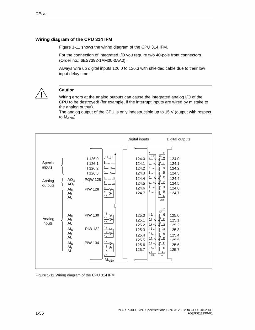
CPUs
1-56PLC S7-300, CPU Specifications CPU 312 IFM to CPU 318-2 DP
A5E00111190-01
Wiring diagram of the CPU 314 IFM
Figure 1-11 shows the wiring diagram of the CPU 314 IFM.
For the connection of integrated I/O you require two 40-pole front connectors(Order no.: 6ES7392-1AM00-0AA0).
Always wire up digital inputs 126.0 to 126.3 with shielded cable due to their lowinput delay time.
!Caution
Wiring errors at the analog outputs can cause the integrated analog I/O of theCPU to be destroyed! (for example, if the interrupt inputs are wired by mistake tothe analog output).The analog output of the CPU is only indestructible up to 15 V (output with respectto MANA).
1M
1 L+
3L+
3M
2L+
2M
1 L+
MANA
Special inputs
Analog outputs
Analog inputs
I 126.0I 126.1I 126.2I 126.3
PQW 128
PIW 128
PIW 130
PIW 132
PIW 134
AOUAOI
AIUAIIAI-
AIUAIIAI-AIUAIIAI-AIUAIIAI-
124.0124.1124.2124.3124.4124.5124.6124.7
125.0125.1125.2125.3125.4125.5125.6125.7
124.0124.1124.2124.3124.4124.5124.6124.7
125.0125.1125.2125.3125.4125.5125.6125.7
Digital inputs Digital outputs
Figure 1-11 Wiring diagram of the CPU 314 IFM
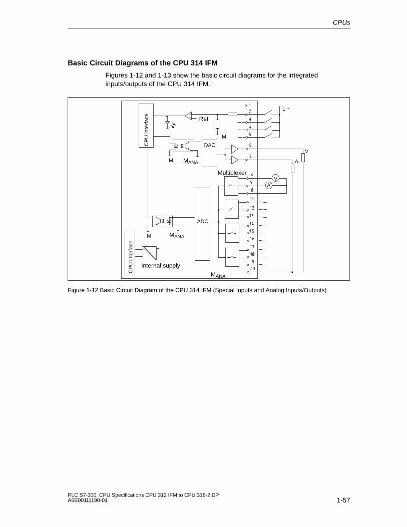
CPUs
1-57PLC S7-300, CPU Specifications CPU 312 IFM to CPU 318-2 DPA5E00111190-01
Basic Circuit Diagrams of the CPU 314 IFM
Figures 1-12 and 1-13 show the basic circuit diagrams for the integratedinputs/outputs of the CPU 314 IFM.
L +
DAC
Internal supply
+� Ref
M
ADC
VA
MANA
MANA
Multiplexer
V
A
MANA
CP
U in
terf
ace
CP
U in
terf
ace
M
M
Figure 1-12 Basic Circuit Diagram of the CPU 314 IFM (Special Inputs and Analog Inputs/Outputs)

CPUs
1-58PLC S7-300, CPU Specifications CPU 312 IFM to CPU 318-2 DP
A5E00111190-01
1 L+
CPUinterface
24V1M M
2L+
M
2M
3M
24V
24V
3L+
M
Figure 1-13 Basic Circuit Diagram of the CPU 314 IFM (Digital Inputs/Outputs)

CPUs
1-59PLC S7-300, CPU Specifications CPU 312 IFM to CPU 318-2 DPA5E00111190-01
Wiring the Analog Inputs
L +
MANA
AIUAIIAI_
2-wiremeasurementtransducer
AI_ and MANA - we recommend to jumperthem.
1 L+
M
Figure 1-14 Connecting 2-wire measurement transducers to the analog inputs of CPU 314 IFM
1 L+
MANA
AIUAIIAI_
AIUAIIAI_
4-wiremeasurementtransducer
When using 4-wire measurement transducers,we recommend you interconnect AI_ and MANA.
Unwired channel groups:Connect AI_ with MANA.
L + M
M
Shielded cables
Figure 1-15 Wiring of 4-wire measurement transducers to the analog inputs of CPU 314 IFM

CPUs
1-60PLC S7-300, CPU Specifications CPU 312 IFM to CPU 318-2 DP
A5E00111190-01
1.4.5 CPU 315
Technical Specifications of the CPU 315
CPU and Product Version
MLFB
� Hardware version
6ES7 315-5AF03-0AB0
01
� Firmware version V 1.1.0
� Matching programmingpackage
STEP 7 V 5.0;Service Pack 03
Memory
Work memory
� integral 48 KB
� Expandable no
Load memory
� integral 80 KB RAM
� Expandable FEPROM Up to 4 MB
� Expandable RAM no
Backup Yes
� With battery All data
� Without battery 4736 bytes, configurable,(data, flags, timers)
Processing times
Processing times for
� Bit instructions 0.3 �s minimum
� Word instructions 1 �s minimum
� Double integer math 2 �s minimum
� Floating-point mathinstructions
50 �s minimum
Timers/Counters and their retentive characteristics
S7 counters 64
� Adjustable retentivity from C 0 to C 63
� Preset from C 0 to C 7
� Counting range 0 to 999
IEC Counters Yes
� Type SFB
S7 timers 128
� Adjustable retentivity from T 0 to T 127
� Preset No retentive times
� Timing range 10 ms to 9990 s
IEC Timers Yes
� Type SFB
Data areas and their retentive characteristics
Retentive data area as awhole (inc. flags, timers,counters)
4736 bytes
Bit memories 2048
� Adjustable retentivity MB 0 to MB 255
� Preset MB 0 to MB 15
Clock memories 8 (1 memory byte)
Data blocks max. 255 (DB 0 reserved)
� Size max. 16 KB
� Adjustable retentivity max. 8 DB, 4096 data bytesin all
� Preset No retentivity
Local data (non-alterable) max. 1536 bytes
� Per priority class 256 bytes
Blocks
OBs See Instruction List
� Size max. 16 KB
Nesting depth
� Per priority class 8
� additional levels withinan error OB
4
FBs max. 192
� Size max. 16 KB
FCs max. 192
� Size max. 16 KB
Address areas (I/O)
Peripheral address area
Digital/Analog 1 KB/1 KB (freelyaddressable)
Process image (cannot becustomized)
128 bytes/128 bytes
Digital channels max. 1024/1024
Analog channels max. 256/128

CPUs
1-61PLC S7-300, CPU Specifications CPU 312 IFM to CPU 318-2 DPA5E00111190-01
Configuration
Rack max. 4
Modules per module rack max. 8
Number of DP masters
� integral None
� via CP 1
S7 message functions
Simultaneously active
Alarm-S blocks
50
Time
Real-time clock Yes
� Backed-up Yes
� Accuracy See Section 1.1.6
Operating hours counter 1
� Number 0
� Value range 0 to 32767 hours
� Selectivity 1 hour
� Retentive Yes
Clock synchronisation Yes
� On PLC Master
� On MPI Master/Slave
Testing and commissioning functions
Status/Modify Variables Yes
� Variable Inputs, outputs, flags, DPs,timers, counters
� Number
– Monitor Variables
– Modify Variables
max. 30
max. 14
Force Yes
� Variable Inputs, outputs
� Number max. 10
Monitor block Yes
Single sequence
Breakpoint
Yes
2
Diagnostic buffer Yes
� Number of entries(non-alterable)
100
Communication functions
PD/OP communication Yes
Global data communication Yes
� Number of GD packets
– Sender 1
– Receiver 1
� Size of GD packets max. 22 bytes
– Number of whichconsistent
8 bytes
S7 basic communication Yes
� User data per job max. 76 bytes
– Number of whichconsistent
32 bytes for X/I_PUT/_GET;
76 bytes forX_SEND/_RCV
S7 communication Yes (server)
� User data per job max. 160 bytes
– Number of whichconsistent
32 bytes
S7-compatiblecommunication
Yes (via CP and loadableFC)
� User data per job Dependent on CP
– Number of whichconsistent
Dependent on CP
Standard communication Yes (via CP and loadableFC)
� User data per job Dependent on CP
– Number of whichconsistent
Dependent on CP
Number of connectionresources
12 for PD/OP/S7 basic/S7communication
� Reservation for
– PD communicationUser-definableDefault
max. 11from 1 to 111
– OP communicationUser-definableDefault
max. 11from 1 to 111
– S7 basiccommunication User-definableDefault
max. 8
from 0 to 88
Interfaces
1. Interface
Functionality
� MPI Yes
� DP Master No
� DP Slave No
� Galvanically isolated No

CPUs
1-62PLC S7-300, CPU Specifications CPU 312 IFM to CPU 318-2 DP
A5E00111190-01
MPI
� Services
– PD/OPcommunication
Yes
– Global datacommunication
Yes
– S7 basiccommunication
Yes
– S7 communication Yes (server)
� Transmission rates 19.2; 187.5 Kbps
Dimensions
Assembly dimensionB�H�T (mm)
80�125�130
Weight Approx. 0.53 kg
Programming
Programming language STEP 7
Stored instructions See Instruction List
Nesting levels 8
System functions (SFCs) See Instruction List
System function blocks(SFBs)
See Instruction List
User program security Password protection
Voltages, Currents
Power supply 24V DC
� Permissible range 20.4 to 28.8 V
Current consumption (idle) typical 7.0 A
Inrush current typical 8A
l 2 t 0.4 A2s
External fusing for supplylines (recommendation)
Circuit breaker; 2 A
Type B or C
PD supply at MPI (15 to30V DC)
max. 200 mA
Power losses typical 8 W
Battery Yes
� Backup margin at 25�C and continuous CPUbuffering
min. 1 year
� Battery shelf life at25�C
approx. 5 years
Accumulator Yes
– at 0 to 25�C Approx. 4 weeks
– at 40� C Approx. 3 weeks
– at 60 � C Approx. 1 week
� Battery charging time Approx. 1 hour
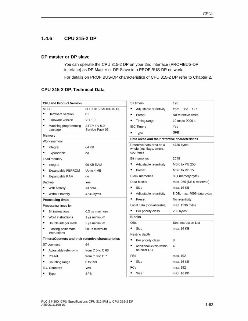
CPUs
1-63PLC S7-300, CPU Specifications CPU 312 IFM to CPU 318-2 DPA5E00111190-01
1.4.6 CPU 315-2 DP
DP master or DP slave
You can operate the CPU 315-2 DP on your 2nd interface (PROFIBUS-DPinterface) as DP Master or DP Slave in a PROFIBUS-DP network.
For details on PROFIBUS-DP characteristics of CPU 315-2 DP refer to Chapter 2.
CPU 315-2 DP, Technical Data
CPU and Product Version
MLFB
� Hardware version
6ES7 315-2AF03-0AB0
01
� Firmware version V 1.1.0
� Matching programmingpackage
STEP 7 V 5.0;Service Pack 03
Memory
Work memory
� integral 64 KB
� Expandable no
Load memory
� integral 96 KB RAM
� Expandable FEPROM Up to 4 MB
� Expandable RAM no
Backup Yes
� With battery All data
� Without battery 4736 bytes
Processing times
Processing times for
� Bit instructions 0.3 �s minimum
� Word instructions 1 �s minimum
� Double integer math 2 �s minimum
� Floating-point mathinstructions
50 �s minimum
Timers/Counters and their retentive characteristics
S7 counters 64
� Adjustable retentivity from C 0 to C 63
� Preset from C 0 to C 7
� Counting range 0 to 999
IEC Counters Yes
� Type SFB
S7 timers 128
� Adjustable retentivity from T 0 to T 127
� Preset No retentive times
� Timing range 10 ms to 9990 s
IEC Timers Yes
� Type SFB
Data areas and their retentive characteristics
Retentive data area as awhole (inc. flags, timers,counters)
4736 bytes
Bit memories 2048
� Adjustable retentivity MB 0 to MB 255
� Preset MB 0 to MB 15
Clock memories 8 (1 memory byte)
Data blocks max. 255 (DB 0 reserved)
� Size max. 16 KB
� Adjustable retentivity 8 DB; max. 4096 data bytes
� Preset No retentivity
Local data (non-alterable) max. 1536 bytes
� Per priority class 256 bytes
Blocks
OBs See Instruction List
� Size max. 16 KB
Nesting depth
� Per priority class 8
� additional levels withinan error OB
4
FBs max. 192
� Size max. 16 KB
FCs max. 192
� Size max. 16 KB

CPUs
1-64PLC S7-300, CPU Specifications CPU 312 IFM to CPU 318-2 DP
A5E00111190-01
Address areas (I/O)
Peripheral address area,digital/analog
1 KB/1 KB (freelyaddressable)of these are
� distributed 1 KB/1 KB
Process image (cannot becustomized)
128/128 bytes
Digital channels max. 8192 (minus 1 bytediagnostic address per DPslave)/8192
� Centralized max. 1024/1024
Analog channels max. 512 (minus 1 bytediagnostic address per DPslave)/512
� Centralized max. 256/128
Configuration
Rack max. 4
Modules per module rack max. 8
Number of DP masters
� integral 1
� via CP 1
S7 message functions
Simultaneously active
Alarm-S blocks
max. 50
Time
Real-time clock Yes
� Backed-up Yes
� Accuracy See Section 1.1.6
Operating hours counter 1
� Number 0
� Value range 0 to 32767 hours
� Selectivity 1 hour
� Retentive Yes
Clock synchronisation Yes
� On PLC Master
� CP on MPI Master/Slave
Testing and commissioning functions
Status/Modify Variables Yes
� Variable Inputs, outputs, flags, DBs,timers, counters
� Number
– Monitor Variables
– Modify Variables
max. 30
max. 14
Force Yes
� Variable Inputs, outputs
� Number max. 10
Monitor block Yes
Single sequence
Breakpoint
Yes
2
Diagnostic buffer Yes
� Number of entries(non-alterable)
100
Communication functions
PD/OP communication Yes
Global data communication Yes
� Number of GD packets
– Sender 1
– Receiver 1
� Size of GD packets max. 22 bytes
– Number of whichconsistent
8 bytes
S7 basic communication Yes (server)
� User data per job max. 76 bytes
– Number of whichconsistent
32 bytes for X/I_PUT/_GET;
76 bytes forX_SEND/_RCV
S7 communication Yes
� User data per job max. 160 bytes
– Number of whichconsistent
32 bytes
S7-compatiblecommunication
Yes (via CP and loadableFC)
� User data per job Dependent on CP
– Number of whichconsistent
Dependent on CP
Standard communication Yes (via CP and loadableFC)
� User data per job Dependent on CP
– Number of whichconsistent
Dependent on CP
Number of connectionresources
12 for PD/OP/S7 basic/S7communication
� Reservation for
– PD communicationUser-definableDefault
max. 11from 1 to 111
– OP communicationUser-definableDefault
max. 11from 1 to 111
– S7 basiccommunication User-definableDefault
max. 8
from 0 to 88
Routing connections max. 4

CPUs
1-65PLC S7-300, CPU Specifications CPU 312 IFM to CPU 318-2 DPA5E00111190-01
Interfaces
1. Interface
Functionality
� MPI Yes
� DP Master No
� DP Slave No
� Galvanically isolated No
MPI
� Services
– PD/OPcommunication
Yes
– Global datacommunication
Yes
– S7 basiccommunication
Yes
– S7 communication Yes (server)
� Transmission rates 19.2; 187.5 Kbps
2. Interface
Functionality
� DP Master Yes
� DP Slave Yes
– Status/Modify;Program; Routing
Yes, can be activated
� Direct data exchange Yes
� Point-to-pointconnection
No
� Default setting None
� Galvanically isolated Yes
DP Master
� Services
– Equidistance Yes
– SYNC/FREEZE Yes
– Activation/deactivation of DP slaves
Yes
� Transmission rates Up to 12 Mbps
� Number of DP slaves max. 64
� Address area max. 1 KB I/1 Kbyte O
� User data per DP slave max. 244 bytes I and244 bytes O
DP Slave
� Services
– Status/Modify;Program viaPROFIBUSRouting
Yes, can be activated
� Device master file Sie3802f.gsg
� Transmission rate ... up to 12 Mbps
� Transfer memory 244 bytes I/244 bytes O
– Address areas max. 32 with max. 32 byteseach
Dimensions
Assembly dimensionB�H�T mm
(mm)
80�125�130
Weight Approx. 0.53 kg
Programming
Programming language STEP 7
Stored instructions See Instruction List
Nesting levels 8
System functions (SFCs) See Instruction List
System function blocks(SFBs)
See Instruction List
User program security Password protection
Voltages, Currents
Power supply 24V DC
� Permissible range 20.4 to 28.8 V
Current consumption (idle) typical 0.9 A
Inrush current typical 8A
l 2 t 0.4 A2s
External fusing for supplylines (recommendation)
Circuit breaker; 2 A,
Type B or C
PD supply at MPI (15 to30V DC)
max. 200 mA
Power losses typical 10 W
Battery Yes
� Backup margin at 25�C and continuous CPUbuffering
min. 1 year
� Battery shelf life at25�C
approx. 5 years
Accumulator Yes
– at 0 to 25�C Approx. 4 weeks
– at 40� C Approx. 3 weeks
– at 60 � C Approx. 1 week
� Battery charging time Approx. 1 hour

CPUs
1-66PLC S7-300, CPU Specifications CPU 312 IFM to CPU 318-2 DP
A5E00111190-01
1.4.7 CPU 316-2 DP
DP master or DP slave
You can operate the CPU 316-2 DP on your 2nd interface (PROFIBUS-DPinterface) as DP Master or DP Slave in a PROFIBUS-DP network.
For details on PROFIBUS-DP characteristics of CPU 316-2 DP refer to Chapter 2.
CPU 316-2 DP, Technical Data
CPU and Product Version
MLFB
� Hardware version
6ES57 316-2AG00-0AB0
01
� Firmware version V 1.1.0
� Matching programmingpackage
STEP 7 V 5.0;Service Pack 03
Memory
Work memory
� integral 128 KB
� Expandable no
Load memory
� integral 192 KB
� Expandable FEPROM Up to 4 MB
� Expandable RAM no
Backup Yes
� With battery All data
� Without battery 4736 bytes
Processing times
Processing times for
� Bit instructions 0.3 �s minimum
� Word instructions 1 �s minimum
� Double integer math 2 �s minimum
� Floating-point mathinstructions
50 �s minimum
Timers/Counters and their retentive characteristics
S7 counters 64
� Adjustable retentivity from C 0 to C 63
� Preset from C 0 to C 7
� Counting range 0 to 999
IEC Counters Yes
� Type SFB
S7 timers 128
� Adjustable retentivity from T 0 to T 127
� Preset No retentive times
� Timing range 10 ms to 9990 s
IEC Timers Yes
� Type SFB
Data areas and their retentive characteristics
Retentive data area as awhole (inc. flags, timers,counters)
4736 bytes
Bit memories 2048
� Adjustable retentivity MB 0 to MB 255
� Preset MB 0 to MB 17
Clock memories 8 (1 memory byte)
Data blocks 511 (DB 0 reserved)
� Size max. 16 KB
� Adjustable retentivity max. 8 DB 4096 data bytes
� Preset No retentivity
Local data (non-alterable) max. 1536 bytes
� Per priority class 256 bytes
Blocks
OBs See Instruction List
� Size max. 16 KB
Nesting depth
� Per priority class 8
� additional levels withinan error OB
4
FBs max. 256
� Size max. 16 KB
FCs max. 256
� Size max. 16 KB

CPUs
1-67PLC S7-300, CPU Specifications CPU 312 IFM to CPU 318-2 DPA5E00111190-01
Address areas (I/O)
Peripheral address area,digital/analog
2 KB/2 KB (freelyaddressable)
� Distributed 2 KB/2 KB
Process image (cannot becustomized)
128/128 bytes
Digital channels max. 16384 (minus 1 bytediagnostic address per DPslave)/16384
� Centralized max. 1024/1024
Analog channels max. 1024 (minus 1 bytediagnostic address per DPslave)/1024
� Centralized max. 256/128
Configuration
Rack max. 4
Modules per
Rack
max. 8
Number of DP masters
� integral 1
� via CP 1
S7 message functions
Simultaneously active
Alarm-S blocks
max. 50
Time
Real-time clock Yes
� Backed-up Yes
� Accuracy See Section 1.1.6
Operating hours counter 1
� Number 0
� Value range 0 to 32767 hours
� Selectivity 1 hour
� Retentive Yes
Clock synchronisation Yes
� On PLC Master
� On MPI Master/Slave
Testing and commissioning functions
Status/Modify Variables Yes
� Variable Inputs, outputs, flags, DBs,timers, counters
� Number
– Monitor Variables
– Modify Variables
max. 30
max. 14
Force Yes
� Variable Inputs, outputs
� Number max. 10
Monitor block Yes
Single sequence
Breakpoint
Yes
2
Diagnostic buffer Yes
� Number of entries(non-alterable)
100
Communication functions
PD/OP communication Yes
Global data communication Yes
� Number of GD packets
– Sender 1
– Receiver 1
� Size of GD packets max. 22 bytes
– Number of whichconsistent
8 bytes
S7 basic communication Yes
� User data per job max. 76 bytes
– Number of whichconsistent
32 bytes for X/I_PUT/_GET;
76 bytes forX_SEND/_RCV
S7 communication Yes (server)
� User data per job max. 160 bytes
– Number of whichconsistent
32 bytes
S7-compatiblecommunication
Yes (via CP and loadableFC)
� User data per job Dependent on CP
– Number of whichconsistent
Dependent on CP
Standard communication Yes (via CP and loadableFC)
� User data per job Dependent on CP
– Number of whichconsistent
Dependent on CP
Number of connectionresources
12 for PD/OP/S7 basic/S7communication
� Reservation for
– PD communicationUser-definableDefault
max. 11from 1 to 111
– OP communicationUser-definableDefault
max. 11from 1 to 111
– S7 basiccommunication User-definableDefault
max. 8
from 0 to 88
Routing connections max. 4
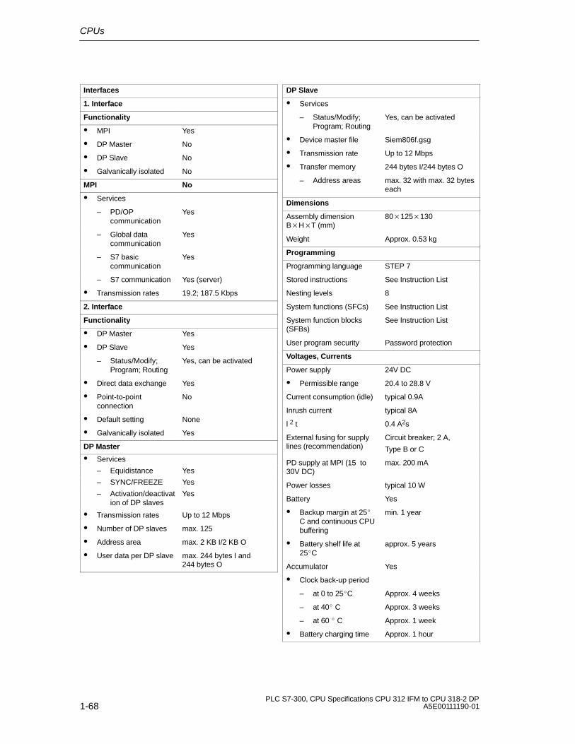
CPUs
1-68PLC S7-300, CPU Specifications CPU 312 IFM to CPU 318-2 DP
A5E00111190-01
Interfaces
1. Interface
Functionality
� MPI Yes
� DP Master No
� DP Slave No
� Galvanically isolated No
MPI No
� Services
– PD/OPcommunication
Yes
– Global datacommunication
Yes
– S7 basiccommunication
Yes
– S7 communication Yes (server)
� Transmission rates 19.2; 187.5 Kbps
2. Interface
Functionality
� DP Master Yes
� DP Slave Yes
– Status/Modify;Program; Routing
Yes, can be activated
� Direct data exchange Yes
� Point-to-pointconnection
No
� Default setting None
� Galvanically isolated Yes
DP Master
� Services
– Equidistance Yes
– SYNC/FREEZE Yes
– Activation/deactivation of DP slaves
Yes
� Transmission rates Up to 12 Mbps
� Number of DP slaves max. 125
� Address area max. 2 KB I/2 KB O
� User data per DP slave max. 244 bytes I and244 bytes O
DP Slave
� Services
– Status/Modify;Program; Routing
Yes, can be activated
� Device master file Siem806f.gsg
� Transmission rate Up to 12 Mbps
� Transfer memory 244 bytes I/244 bytes O
– Address areas max. 32 with max. 32 byteseach
Dimensions
Assembly dimensionB�H�T (mm)
80�125�130
Weight Approx. 0.53 kg
Programming
Programming language STEP 7
Stored instructions See Instruction List
Nesting levels 8
System functions (SFCs) See Instruction List
System function blocks(SFBs)
See Instruction List
User program security Password protection
Voltages, Currents
Power supply 24V DC
� Permissible range 20.4 to 28.8 V
Current consumption (idle) typical 0.9A
Inrush current typical 8A
l 2 t 0.4 A2s
External fusing for supplylines (recommendation)
Circuit breaker; 2 A,
Type B or C
PD supply at MPI (15 to30V DC)
max. 200 mA
Power losses typical 10 W
Battery Yes
� Backup margin at 25�C and continuous CPUbuffering
min. 1 year
� Battery shelf life at25�C
approx. 5 years
Accumulator Yes
� Clock back-up period
– at 0 to 25�C Approx. 4 weeks
– at 40� C Approx. 3 weeks
– at 60 � C Approx. 1 week
� Battery charging time Approx. 1 hour

CPUs
1-69PLC S7-300, CPU Specifications CPU 312 IFM to CPU 318-2 DPA5E00111190-01
1.4.8 CPU 318-2
Special Features
� 4 accumulators
� The configuration of MPI interfaces can be changed: MPI or PROFIBUS DP(DP Master).
� Configurable data areas (Process image, local data)
Information on differences between CPU 318-2 and other CPUs is found inChapter 4.1.
DP master or DP slave
You can operate the CPU 318-2 DP as DP Master or DP Slave in aPROFIBUS-DP network. However, note that only one of the interfaces can be aDP Slave. For details on PROFIBUS-DP characteristics of CPU 318-2 DP refer toChapter 2.
Definable Data Areas and Occupied Working Memory
In your CPU 318-2 configuration, you can change the size of the I/O processimage and the local data areas.Increasing default values for the process image and local data requires additionalmemory that would otherwise be available for user programs.Take following dimensions into account:
� Input process image: 1 byte PII occupies 12 Byte in memoryOutput process image: 1 Byte PIO occupies 12 bytes in memoryExample: 256 bytes in PII occupy 3072 bytes, 2047 byte in PIO already occupy 24564 bytes in memory.
� Local data 1 local data byte occupies1 byte in memory 256 byte is default, depending on the priority class. With 14 priority classesthere are therefore 3584 bytes occupied in the working memory. With amaximum size of 8192 bytes you can still allocate 4608 bytes, which are thenno longer available for the user program in the working memory.
Communication
You can transform the first CPU interface from MPI to DP interface operation. Youcan operate the CPU as DP Master or DP Slave on this DP interface. Routingreduces the maximum possible number of connections for each one of the twointerfaces by one connection per active PG/OP communication used by the CPU318-2 as network node.

CPUs
1-70PLC S7-300, CPU Specifications CPU 312 IFM to CPU 318-2 DP
A5E00111190-01
FM 353/354, distributed
If you implement the CPU 318-2 as DP Master, you can operate FM 353 as of6ES7 353-1AH01-0AE0, firmware version 3.4/03 and FM 354 as of 6ES7354-1AH01-0AE0, firmware version 3.4/03 in distributed mode with an ET 200M.
You cannot operate the following modules in an S7-300 equipped with a 318-2CPU
FM 357 up to 6ES7 357-4_H02-3AE_, firmware version 2.1;
FM NC up to 6FC5 250-3AX00-7AH0, firmware version 3.7 + Toolbox 6FC5252-3AX2Z-6AB0, Software Version 3.6;
SM 338 up to 6ES7 338-7UH00-0AC0, version 07;
SIXWAREX M up to 7MH4 553-1AA41, firmware version 0119;
SINAUT ST7 TIM, 6NH7 800-_A__0 (Tip: Use a TIM module as stand alone node)
Peripheral access in CPU 318-2 is not permitted
for T PAW operations on centrally inserted peripheral modules with correspondingaddress bytes assigned to different peripheral modules.

CPUs
1-71PLC S7-300, CPU Specifications CPU 312 IFM to CPU 318-2 DPA5E00111190-01
CPU 318-2, Technical DataCPU and Product Version
MLFB
� Hardware version
6ES7 318-2AJ00-0AB0
03
� Firmware version V 3.0
� Matching programmingpackage
STEP 7 V 5.1 +Service Pack 02
Memory
Work memory
� integral 256 KB data/256 KB code
� Expandable no
Load memory
� integral 64 KB
� Expandable FEPROM Up to 4 MB
� Expandable RAM Up to 2 MB
Backup Yes
� With battery All data
� Without battery max. 11 KB
Processing times
Processing times for
� Bit instructions 0.1 �s minimum
� Word instructions 0.1 �s minimum
� Double integerarithmetic
0.1 �s minimum
� Floating-pointarithmetic
0.6 �s minimum
Timers/Counters and their retentive characteristics
S7 counters 512
� Adjustable retentivity from C 0 to C 511
� Preset from C 0 to C 7
� Counting range 0 to 999
IEC Counters Yes
� Type SFB
S7 timers 512
� Adjustable retentivity from T 0 to T 511
� Preset No retentive times
� Timing range 10 ms to 9990 s
IEC Timers Yes
� Type SFB
Data areas and their retentive characteristics
Retentive data area as awhole (inc. flags, timers,counters)
max. 11 KB
Bit memories 8192
� Adjustable retentivity MB 0 to MB 1023
� Preset MB 0 to MB 15
Clock memories 8 (1 memory byte)
Data blocks 2047 (DB 0 reserved)KB
� Size max. 64 KB
� Adjustable retentivity max. 8 DB, max. 8192 databytes
� Preset No retentivity
Local data (alterable) max. 8192 bytes
� Preset 3584 bytes
� Per priority class 256 bytes (expandable to8192 bytes)
Blocks
OBs See Instruction List
� Size max. 64 KB
Nesting depth
� Per priority class 16
� additional levels withinan error OB
3
FBs max. 1024
� Size max. 64 KB
FCs max. 1024
� Size max. 64 KB
Address areas (I/O)
Peripheral address area,digital/analog
max. 8 KB/8 KB (freelyaddressable)
� Distributed
– MPI/DP Interface max. 2 KB/2 KB
– DP interface max. 8 KB/8 KB
Process image(configurable)
2048/2048 bytes
� Preset 256/256 bytes
Digital channels max. 65536 (minus 1 bytediagnostic address per DPslave)/65536
� Centralized max. 1024/1024
Analog channels max. 4096/4096
� Centralized max. 256/128

CPUs
1-72PLC S7-300, CPU Specifications CPU 312 IFM to CPU 318-2 DP
A5E00111190-01
Configuration
Rack max. 4
Modules per module rack max. 8
Number of DP masters
� integral 2
� via CP 2
S7 message functions
Simultaneously active
Interrupt S function blocksand
Interrupt D function blocksmax. 100
Time
Real-time clock Yes
� Backed-up Yes
� Accuracy See Section 1.1.6
Operating hours counter 8
� Number 0 to 7
� Value range 0 to 32767 hours
� Selectivity 1 hour
� Retentive Yes
Clock synchronisation Yes
� On PLC Master/Slave
� via MPI
� via DP
Master/Slave
Master/Slave
Testing and commissioning functions
Status/Modify Variables Yes
� Variable Inputs, outputs, flags, DBs,timers, counters
� Number max. 70
Force Yes
� Variable Inputs, outputs, flags,peripheral inputs, peripheraloutputs
� Number max. 256
Monitor block Yes
Single sequence
Breakpoint
Yes
4
Diagnostic buffer
� Number of entries(non-alterable)
100
Communication functions
PD/OP communication Yes
Global data communication Yes
� Number of GD packets
– Sender 1
– Receiver 2
� Size of GD packets 54 bytes
– Number of whichconsistent
32 bytes
S7 basic communication Yes
� User data per job max. 76 bytes
– Number of whichconsistent
76 bytes
S7 communication Yes (server)
� User data per job max. 160 bytes
– Number of whichconsistent
Byte, Word, Double word
S7-compatiblecommunication
Yes (via CP and loadableFC)
� User data per job Dependent on CP
– Number of whichconsistent
Dependent on CP
Standard communication Yes (via CP and loadableFC)
� User data per job Dependent on CP
– Number of whichconsistent
Dependent on CP
Interfaces
1. Interface
Functionality
� MPI Yes
� DP Master Yes
� DP Slave Yes
� Direct data exchange Yes
� Default setting MPI
� Electrically isolated Yes
Number of connections max. 32;
– Of these, thefollowing arereserved:
1 PD connection
1 OP connection
MPI
� Services
– PD/OPcommunication
Yes
– Global datacommunication
Yes
– S7 basiccommunication
Yes
– S7 communication Yes (server)
� Transmission rates Up to 12 Mbps

CPUs
1-73PLC S7-300, CPU Specifications CPU 312 IFM to CPU 318-2 DPA5E00111190-01
DP Master
� Services
– Equidistance Yes
– SYNC/FREEZE Yes
– Activation/deactivation of DP slaves
Yes
� Transmission rates Up to 12 Mbps
� Address area max. 2 KB I/2 KB O
� User data per DP slave max. 244 bytes I and244 bytes O
DP Slave
� Services
– Status/Modify;Program; Routing
Yes, can be activated
� Device master file siem807f.gsg
� Transmission rate Up to 12 Mbps
� Transfer memory 244 bytes I/244 bytes O
2. Interface
Functionality
� DP Master Yes
� DP Slave Yes
– Status/Modify;Program; Routing
Yes, can be activated
� Direct data exchange Yes
� PtP Connection No
� Default setting None
� Galvanically isolated Yes
Number of connections max. 16
– Of these, thefollowing arereserved:
1 PD connection
1 OP connection
DP Master
� Services
– PD/OPcommunication
Yes
– Equidistance Yes
– SYNC/FREEZE Yes
– Activation/deactivation of DP slaves
Yes
� Transmission rates Up to 12 Mbps
� Number of DP slaves max. 125
� Address area max. 8 KB I/8 KB O
� User data per DP slave max. 244 bytes I and244 bytes O
DP Slave
� Services
– Status/Modify;
Program;
Routing
� GSD file
� Transmission speed
� Transfer memory
Yes, can be activated
siem807f.gsg
Up to 12 Mbps
244 bytes I/244 bytes O
Dimensions
Assembly dimensionB�H�T (mm)
160�125�130
Weight Approx. 0.93 kg
Programming
Programming language STEP 7
Stored instructions See Instruction List
Nesting levels 16
System functions (SFCs) See Instruction List
System function blocks(SFBs)
See Instruction List
User program security Password protection
Voltages, Currents
Power supply 24V DC
� Permissible range 20.4 V to 28.8 V
Current consumption (idle) typical 1.2 A
Inrush current typical 8A
l 2 t 0.4 A2s
External fusing for supplylines (recommendation)
Circuit breaker; 2 A,
Type B or C
PD supply at MPI (15 to30V DC)
max. 200 mA
Power losses typical 12 W
Battery Yes
� Backup margin at 25�C and continuous CPUbuffering
min. 1 year
� Battery shelf life at25�C
approx. 5 years
Accumulator Yes
� Clock back-up period
– at 0 to 25�C Approx. 4 weeks
– at 40� C Approx. 3 weeks
– at 60 � C Approx. 1 week
� Battery charging time Approx. 1 hour

CPUs
1-74PLC S7-300, CPU Specifications CPU 312 IFM to CPU 318-2 DP
A5E00111190-01

2-1PLC S7-300, CPU Specifications CPU 312 IFM to CPU 318-2 DPA5E00111190-01
CPU 31x-2 as DP Master/DP Slave andDirect Communication
Introduction
In this chapter you will find the features and technical specifications of the CPUs315-2 DP, 316-2DP and 318-2. You will need these in order to use the CPU as aDP master or a DP slave and configure it for direct communication.
Agreement: Since DP Master/Slave behavior is the same for all CPUs, the CPUsdescribed below are referred to as CPU 31x-2.
Note on CPU 318-2: With a CPU 318-2 you can operate the MPI-/DP interface asDP interface. In this case, however, you can only configure it as DP Master andnot as DP Slave.
In This Chapter
Section Contents Page
2.1 Information on DPV1 Functionality 2-2
2.2 DP Address Areas of the CPUs 31x-2 2-4
2.3 CPU 31x-2 as DP Master 2-5
2.4 Diagnostics of the CPU 31x-2 as DP Master 2-6
2.5 CPU 31x-2 as DP Slave 2-13
2.6 Diagnostics of the CPU 31x-2 as DP Slave 2-18
2.7 Direct data exchange 2-32
2.8 Diagnosis with Direct Communication 2-33
Additional Literature
Descriptions and notes on system configuration, configuration of a PROFIBUSsubnet and on diagnostics in a PROFIBUS subnet is found in the STEP 7 OnlineHelp.
2
CPU 31x-2 as DP Master/DP Slave and Direct Communication
2-2PLC S7-300, CPU Specifications CPU 312 IFM to CPU 318-2 DP
A5E00111190-01
2.1 Information on DPV1 Functionality
The aim
The EN50170 Standard for Distributed Peripherals was subject to furtherdevelopment. All changes were incorporated in IEC 61158 / EN 50170,Volume 2, PROFIBUS. In order to simplify matters we now refer to DPV1Mode.
How do I identify a DPV1 Master/Slave?
DP Master CPUs of the S7-400 family and the CPU 318-2, respectively withintegrated DP interface, support DPV1 Master functionality as of Firmware Version3.0.0.
DP Slaves, listed in the STEP 7 hardware catalog under their family name can beidentified as DPV1 Slaves with the help of the info text. DP Slaves implemented inSTEP 7 via GSD files support V1 functionality as of GSD Revision 3.
As of which STEP 7 version is migration to DPV1 mode possible?
As of STEP 7 V5.1, Servicepack 2.
Which operating modes are available for DPV1 modules?
You are using a DPV1 automation module, but do not want to migrate to DPV1mode. In this case you use S7 compatible mode. In this mode, the automationmodule is compatible to EN50170. In this case, however, you cannot utilize fullDPV1 functionality. You could, for example, use the new SFBs 52...54. However,default values are written to non-existing data.
You are using a DPV1 compatible automation module and want to migrate to DPV1mode. In this case, use DPV1 mode for full functionality. In your station you cancontinue using automation modules not supporting DPV1 as usual.
Can I use all previous slaves after migration to DPV1 mode?
Yes, without restriction. The only difference here is that your previous slaves do notsupport extended DPV1 functions.

CPU 31x-2 as DP Master/DP Slave and Direct Communication
2-3PLC S7-300, CPU Specifications CPU 312 IFM to CPU 318-2 DPA5E00111190-01
Can I use DPV1 Slaves without this migration?
Yes, without restriction. In this case, DPV1 Slaves behave as conventional Slaves.SIEMENS DPV1 Slaves can also be operated in S7 compatible mode. For DPV1Slaves of other manufacturers you require a GSD file to EN50170 below Revision3. DPV1 – station-wide.
You must convert the complete station to DPV1 mode if you migrate to DPV1. InSTEP 7 you can configure this mode in the HW Config module (DP Mode).
Details on migration to DPV1 mode are found in our Customer Supportunder FAQ topic ID: 7027576

CPU 31x-2 as DP Master/DP Slave and Direct Communication
2-4PLC S7-300, CPU Specifications CPU 312 IFM to CPU 318-2 DP
A5E00111190-01
2.2 DP Address Areas of the CPUs 31x-2
Address areas of CPUs 31x-2
Address area 315-2 DP 316-2DP 318-2
DP address areafor I/Os
1024 bytes 2048 bytes 8192 bytes
of these in the I/Oprocess images
Bytes 0 to 127 Bytes 0 to 127 Bytes 0 to 255(default)
Can be set up tobyte 2047
In the input address area, DP diagnostic addresses occupy 1 byte for the DPmaster and for each DP slave. Under these addresses, for example, you can callDP standard diagnostics for the respective nodes (LADDR parameter of SFC13).The DP diagnostic addresses are specified during configuration. If you do notspecify any DP diagnostic addresses, STEP 7 assigns these addresses, indecrements starting at the highest byte.
Configuring modules with addresses assigned to the peripheral area
Always configure a module address in a peripheral area either completely inside orcompletely outside of the process image. Otherwise, consistency is not ensuredand corrupted data might be generated.

CPU 31x-2 as DP Master/DP Slave and Direct Communication
2-5PLC S7-300, CPU Specifications CPU 312 IFM to CPU 318-2 DPA5E00111190-01
2.3 CPU 31x-2 as DP Master
Introduction
This section covers the features and technical specifications of the CPU when it isused as a DP master.
The features and technical specifications of the CPU 31x-2 as the “standard” CPUare listed in Section 1.
Prerequisite
Should the MPI/DP interface be a DP interface? If so, you must then configure theinterface as a DP interface.
Before the CPU can be put into operation, it must be configured as a DP master.This means carrying out the following steps in STEP 7 :
� Configure the CPU as a DP master.
� Assign a PROFIBUS address.
� Assign a master diagnostic address.
� Integrate DP slaves into the DP master system.
Is a DP slave a CPU 31x-2?
If so, you will find that DP slave in the PROFIBUS-DP catalog as“pre-configured station”. This DP slave CPU must be assigned a slavediagnostic address in the DP master. Interconnect the DP master and the DPslave CPU. Specify the address areas for data exchange with the DP slaveCPU.
Status/Control, Programming via PROFIBUS
As an alternative to the MPI interface, you can program the CPU viaPROFIBUS-DP interface or execute the PG’s status and control functions.
Note
The use of Monitor and Modify via the PROFIBUS-DP interface lengthens the DPcycle.
Equidistance
As of STEP 7 V 5.x you can configure bus cycles of the same length (equidistant)for PROFIBUS subnets. You can find a detailed description of equidistance in theSTEP 7 online help system.

CPU 31x-2 as DP Master/DP Slave and Direct Communication
2-6PLC S7-300, CPU Specifications CPU 312 IFM to CPU 318-2 DP
A5E00111190-01
Power-Up of the DP Master System
CPU 31x-2DP is DP Master CPU 318-2 is DP Master
You can also set power-up time monitoringof the DP slaves with the “Transfer of parameters to modules”parameter.
Using the parameters “Transfer of parameters to modules” and “Ready message from modules” you canset power-up time monitoring for the DPslaves.
This means that the DP slaves must be powered up and configured by the CPU (as DPmaster) in the set time.
PROFIBUS Address of the DP Master
You cannot set the 126 as the PROFIBUS address for the CPU 31x-2.
2.4 Diagnostics of the CPU 31x-2 as DP Master
Diagnosis with LEDs
Table 2-1 describes the meaning of the BUSF LED.For display the BUSF LED assigned to the PROFIBUS-DP interface is always it orit flashes.
Table 2-1 Meaning of the BUSF LED of the CPU 31x-2 as DP Master
BUSF Description Remedy
LED off Configuring data OK;
all configured slaves are addressable.
–
LED on � Bus fault (hardware fault). � Check for bus cable breaks or short-circuit.
� DP interface fault.
� Different transmission rates inmultiple DP master mode.
� Evaluate the diagnostic data. Reconfigure orcorrect the configuring data.
LEDflashes
� Station failure.
� At least one of the configured slavescannot be addressed.
� Check the bus cable connection to theCPU31x-312, or check whether the bus isinterrupted.
� Wait until the CPU 31x-2 has powered up. If theLED does not stop flashing, check the DPslaves or evaluate the diagnostic data for theDP slaves.

CPU 31x-2 as DP Master/DP Slave and Direct Communication
2-7PLC S7-300, CPU Specifications CPU 312 IFM to CPU 318-2 DPA5E00111190-01
Reading Diagnostic Data with STEP 7
Table 2-2 Reading Diagnostic Data with STEP 7
DP Master Modules orregisters in
STEP 7
Application See...
CPU 31x-2 ”DP slavediagnostics”tab
Display slave diagnostic dataas plain text on the STEP 7user interface
See “Diagnosis of Hardware” inthe STEP 7 Online Help andSTEP 7 User Manual
SFC 13“DPNRM_DG”
Reading out slave diagnosis(store in the data area of theuser program)
Configuration for the CPU 31x-2,see Section 2.6.4; SFC, seeSystem and Standard FunctionsReference ManualConfiguration for other slaves,see their description
SFC 59“RD_REC”
Read out data records of the S7diagnosis (store in the dataarea of the user program)
SFC 51“RDSYSST”
Read out system state sub-lists.In the diagnostics interrupt withthe SSL ID W#16#00B4, callSFC51 and read out the SSL(system diagnostic list) of theslave CPU.
SFB 52“RDREC”(only 318-2)
Applicable to DPV1environment:
Read out data records of the S7diagnosis (store in the dataarea of the user program)
System and Standard Functions
Reference Manual
SFB 54“RALRM”(only 318-2)
Applicable to DPV1environment:
Read out interrupt informationwithin the correspondinginterrupt OB
Evaluating Diagnostics in the User Program
The following figures show you how to evaluate the diagnosis in the user program. Note the order number for the CPU 315-2DP:
CPU 315-2DP < 6ES7 315-2AF03-0AB0 CPU 315-2DP as of 6ES7315-2AF03-0AB0CPU 316-2DP as of 6ES7316-2AG00-0AB0CPU 316-2 as of 6ES7318-2AJ00-0AB0
...see Figure 2-1 on page 2-8 ...see Figure 2-2 on page 2-9
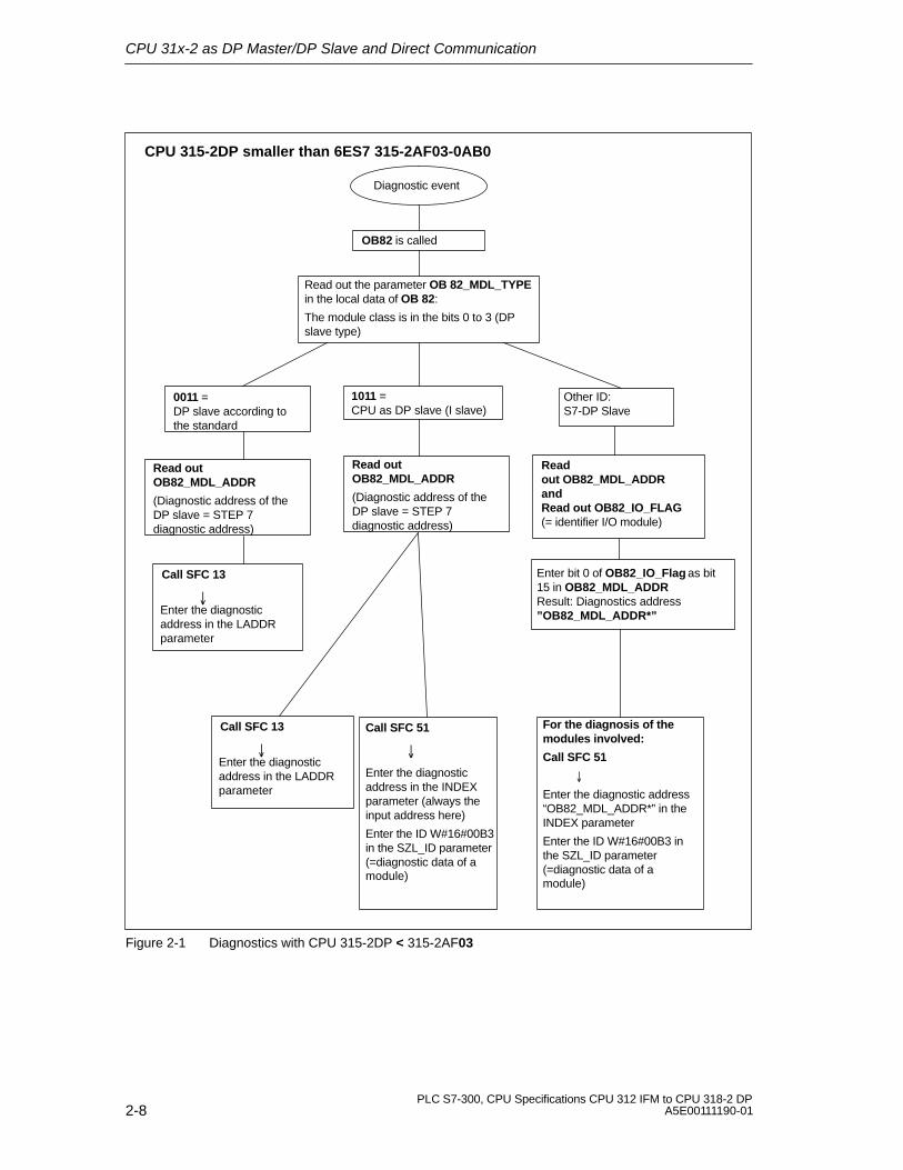
CPU 31x-2 as DP Master/DP Slave and Direct Communication
2-8PLC S7-300, CPU Specifications CPU 312 IFM to CPU 318-2 DP
A5E00111190-01
Read outOB82_MDL_ADDR
(Diagnostic address of theDP slave = STEP 7diagnostic address)
Diagnostic event
OB82 is called
Read out the parameter OB 82_MDL_TYPEin the local data of OB 82:
The module class is in the bits 0 to 3 (DPslave type)
0011 =DP slave according tothe standard
1011 =CPU as DP slave (I slave)
Call SFC 13
�Enter the diagnosticaddress in the LADDRparameter
Read outOB82_MDL_ADDR
(Diagnostic address of theDP slave = STEP 7diagnostic address)
Call SFC 51
�
Enter the diagnosticaddress in the INDEXparameter (always theinput address here)
Enter the ID W#16#00B3in the SZL_ID parameter(=diagnostic data of amodule)
Call SFC 13
�Enter the diagnosticaddress in the LADDRparameter
CPU 315-2DP smaller than 6ES7 315-2AF03-0AB0
Read out OB82_MDL_ADDR andRead out OB82_IO_FLAG (= identifier I/O module)
Enter bit 0 of OB82_IO_Flag as bit15 in OB82_MDL_ADDRResult: Diagnostics address”OB82_MDL_ADDR*”
For the diagnosis of themodules involved:
Call SFC 51
�
Enter the diagnostic address“OB82_MDL_ADDR*” in theINDEX parameter
Enter the ID W#16#00B3 inthe SZL_ID parameter(=diagnostic data of amodule)
Other ID:S7-DP Slave
Figure 2-1 Diagnostics with CPU 315-2DP < 315-2AF03

CPU 31x-2 as DP Master/DP Slave and Direct Communication
2-9PLC S7-300, CPU Specifications CPU 312 IFM to CPU 318-2 DPA5E00111190-01
Diagnostic event
Read out OB82_MDL_ADDRand
Read out OB82_IO_FLAG (= identifier I/O module)
For diagnosis of the whole DP slave:
Call SFC 13
�
Enter the diagnostic address“OB82_MDL_ADDR*” in the LADDRparameter
Enter bit 0 of OB82_IO_Flag as bit15 in OB82_MDL_ADDRResult: Diagnostics address”OB82_MDL_ADDR*”
For the diagnosis of the modules involved:
Call SFC 51
�
Enter the diagnostic address“OB82_MDL_ADDR*” in the INDEX parameter
Enter the ID W#16#00B3 in the SZL_ID parameter(=diagnostic data of a module)
CPU 315-2DP as of 6ES7 315-2AF03-0AB0CPU 3162DP; 318-2
OB82 is called
For the diagnostics of therespective modules:
call SFB 54 (in DPV1 mode)
�
Set MODE = 1
Diagnostic data is written to
the parameters TINFO and
AINFO.
only 318-2
Figure 2-2 Diagnostics with CPU 31x-2 (315-2DP as of 315-2AF03)

CPU 31x-2 as DP Master/DP Slave and Direct Communication
2-10PLC S7-300, CPU Specifications CPU 312 IFM to CPU 318-2 DP
A5E00111190-01
Diagnostic Addresses
With a CPU 31x-2, you assign the diagnostic addresses for the PROFIBUS-DP.Make sure during configuration that DP diagnostic addresses are assigned to boththe DP master and the DP slave.
During configuration you must specify two diagnosticaddresses:
PROFIBUS
CPU 31x-2 as DP SlaveCPU 31x-2 as DP Master
Diagnosticaddress
Diagnosticaddress
When you configure the DP master, youmust specify (in the associated project ofthe DP master) a diagnostic address forthe DP slave. In the following, thisdiagnostic address is referred to asallocated to the DP master.
When you configure the DP slave, youmust also specify (in the associatedproject of the DP slave) a diagnosticaddress that is allocated to the DP slave.In the following, this diagnostic addressis referred to as allocated to the DPslave.
The DP master receives information onthe status of the DP slave or on a businterruption via this diagnostic address(see also Table 2-3).
The DP slave receives information onthe status of the DP master or on a businterruption via this diagnostic address(see also Table 2-8 on page 2-23).
Figure 2-3 Diagnostic Addresses for DP Master and DP Slave

CPU 31x-2 as DP Master/DP Slave and Direct Communication
2-11PLC S7-300, CPU Specifications CPU 312 IFM to CPU 318-2 DPA5E00111190-01
Event Detection
Table 2-3 shows how a DP Master CPU 31x-2 recognizes operating statetransitions of a DP Slave CPU or or data transfer interrupts.
Table 2-3 Event Detection of the CPU 31x-2 as DP Master
Event What Happens in the DP Master
Bus interruption(short-circuit, plugdisconnected)
� OB 86 is called and a station failure reported(incoming event; Diagnostic address of the DP slave, assigned to the DPmaster)
� on peripheral access: Call of OB 122 (Peripheral access error)
DP Slave RUN → STOP
� OB 82 is called and Module fault reported(incoming event; Diagnostic address of the DP slave assigned to the DPmaster; Variable OB82_MDL_STOP=1)
DP Slave STOP → RUN
� Call of OB82 with the message Module OK.(outgoing event; Diagnostic address of the DP slave assigned to the DPmaster; Variable OB82_MDL_STOP=0)

CPU 31x-2 as DP Master/DP Slave and Direct Communication
2-12PLC S7-300, CPU Specifications CPU 312 IFM to CPU 318-2 DP
A5E00111190-01
Evaluation in the User Program
Table 2-4 shows you how you can, for example, evaluate RUN-STOP transitions ofthe DP slave in the DP master (see Table 2-3).
Table 2-4 Evaluating RUN-STOP Transitions of the DP Slaves in the DP Master
In the DP Master In the DP Slave (CPU 31x-2DP)
Diagnostic Addresses Example:Master diagnostic address =1023Slave diagnostic address in the mastersystem =1022
Diagnostic Addresses Example:Slave diagnostic address =422Master diagnostic address = not relevant
The CPU calls OB 82 with the followinginformation:
� OB 82_MDL_ADDR:=1022
� OB82_EV_CLASS:=B#16#39(incoming event)
� OB82_MDL_DEFECT:=Module fault
Tip: The CPU’s diagnostic data buffer alsocontains this information
In your user program, you should alsoprogram SFC13 “DPNRM_DG” to fetchdiagnostic data from the DP Slave.
We recommend you use SFB54 whenoperating in DPV1 mode. It outputs completeinterrupt information.
CPU: RUN → STOP
CPU generates a DP slave diagnostic frame(see Section 2.6.4).

CPU 31x-2 as DP Master/DP Slave and Direct Communication
2-13PLC S7-300, CPU Specifications CPU 312 IFM to CPU 318-2 DPA5E00111190-01
2.5 CPU 31x-2 as DP-Slave
Introduction
This section lists the characteristics and technical specifications for the CPU whenit is operated as a DP slave.
The characteristics and technical specifications of the CPU as the “standard” CPUcan be found in Section 1.
Prerequisite
Should the MPI/DP interface be a DP interface? If so, you must then configure theinterface as a DP interface.
Prior to startup, the CPU must be configured as a DP slave. This means carryingout the following steps in STEP 7:
� “Switch on” the CPU as DP slave.
� Assign a PROFIBUS address.
� Assign a slave diagnostic address.
� Specify the address areas for data exchange with the DP Master.
Device Master Files
You need a device master file to configure the CPU 31x-2 as a DP slave in a DPmaster system.COM PROFIBUS as of V 4.0 includes the GSD file.
If you are working with an older version or another configuration tool, you can getthe device master file from the following sources:
� On the Internet at http://www.ad.siemens.de/csi_e/gsd
or
� Via modem from the SSC (Interface Center) Fuerth by calling 0911/911/737972.
Configuration and parameter assignment message frame
STEP 7 provides support for the configuration and parameter assignment of 31x-2CPUs. If you require a description of the configuration and parameter assignmentmessage frame, for example, to carry out a check using a bus monitor, refer to theInternet URL http://www.ad.siemens.de/simatic-cs, article ID 1452338.
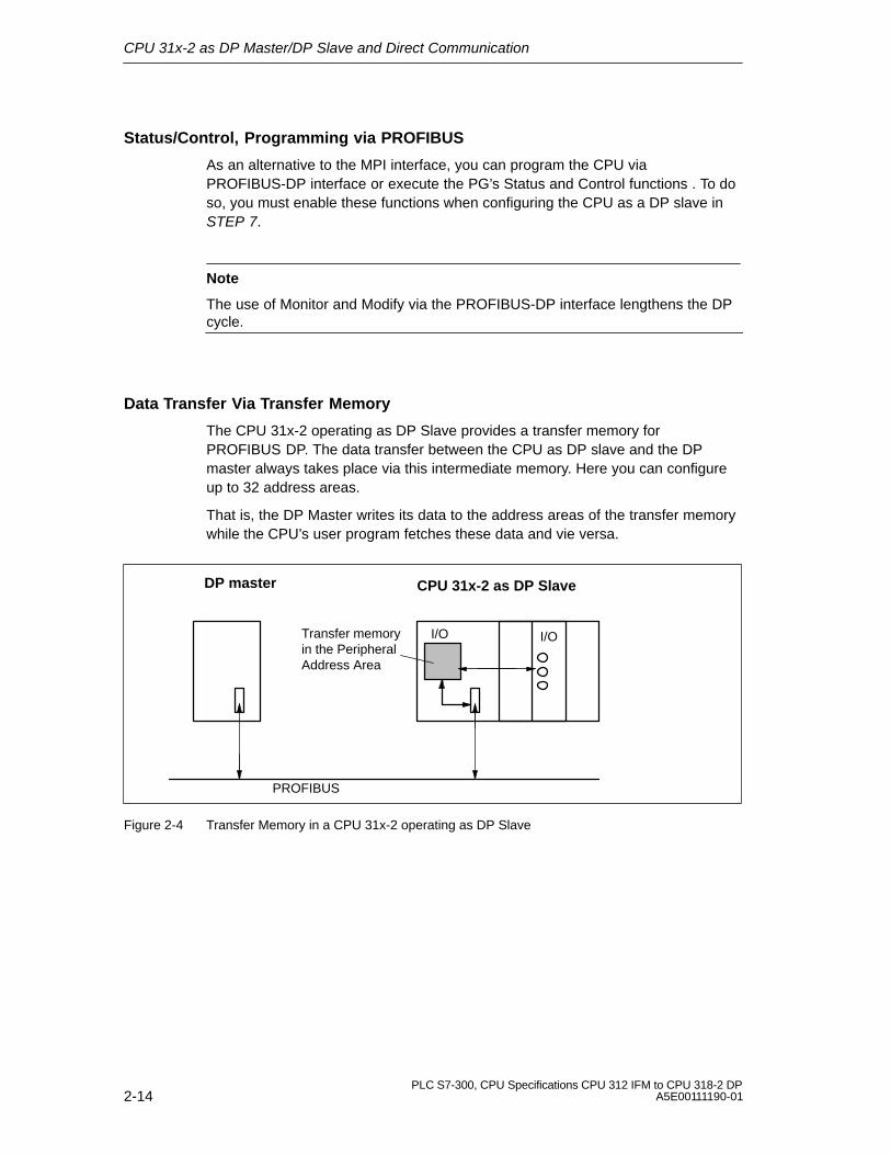
CPU 31x-2 as DP Master/DP Slave and Direct Communication
2-14PLC S7-300, CPU Specifications CPU 312 IFM to CPU 318-2 DP
A5E00111190-01
Status/Control, Programming via PROFIBUS
As an alternative to the MPI interface, you can program the CPU viaPROFIBUS-DP interface or execute the PG’s Status and Control functions . To doso, you must enable these functions when configuring the CPU as a DP slave inSTEP 7.
Note
The use of Monitor and Modify via the PROFIBUS-DP interface lengthens the DPcycle.
Data Transfer Via Transfer Memory
The CPU 31x-2 operating as DP Slave provides a transfer memory forPROFIBUS DP. The data transfer between the CPU as DP slave and the DPmaster always takes place via this intermediate memory. Here you can configureup to 32 address areas.
That is, the DP Master writes its data to the address areas of the transfer memorywhile the CPU’s user program fetches these data and vie versa.
Transfer memoryin the PeripheralAddress Area
PROFIBUS
I/O
CPU 31x-2 as DP SlaveDP master
I/O
Figure 2-4 Transfer Memory in a CPU 31x-2 operating as DP Slave

CPU 31x-2 as DP Master/DP Slave and Direct Communication
2-15PLC S7-300, CPU Specifications CPU 312 IFM to CPU 318-2 DPA5E00111190-01
Address areas of the transfer memory
Configure the I/O address areas in STEP 7:
� you can configure up to 32 I/O address areas
� the maximum length of each one of these address areas is 32 bytes
� You can configure a maximum of 244 bytes for inputs and 244 bytes foroutputs.
The table below shows the principle of address areas. You can also find this figurein the STEP 7 configuration.
Table 2-5 Example of an address area configuration for transfer memory
Type
MasterAddress
Type
SlaveAddress
Length
Unit Consistency
1 E 222 A 310 2 Byte Unit
2 A 0 E 13 10 Word Total length
:
32
Address areas in theDP Master CPU
Address areas in theDP Slave CPU
These address area parametersmust be the same for both the DPMaster and DP Slave
Rules
The following rules must be followed when using the intermediate memory:
� Address area assignment:
– Input data of the DP slave are always output data of the DP master
– Output data of the DP slave are always input data of the DP master
� The addresses can be freely allocated. In the user program, access the datawith Load/Transfer statements or with SFCs 14 and 15. You can also specifyaddresses from the I/O process images.
Note
Transfer memory addresses are assigned from the DP address area of the CPU31x-2.
Do not assign transfer memory addresses to the I/O modules in the CPU 31x-2!
� The lowest address represents the start address of the respective addressarea.
� Length, unit and consistency of DP Master/Slave address areas related to eachother must be identical.

CPU 31x-2 as DP Master/DP Slave and Direct Communication
2-16PLC S7-300, CPU Specifications CPU 312 IFM to CPU 318-2 DP
A5E00111190-01
S5 DP Master
If you are using an IM 308 C as a DP master and the CPU 31x-2 as a DP slave,the exchange of consistent data requires the following:
In the IM 308 C, you must program FB 192 to enable the exchange of consistentdata between DP master and DP slave. FB192 outputs/fetches all CPU 31x-2 datain a single block!
S5-95 as a DP master
If you are using an AG S5-95 as a DP master, you must also set its busparameters for the CPU 31x-2 as a DP slave.

CPU 31x-2 as DP Master/DP Slave and Direct Communication
2-17PLC S7-300, CPU Specifications CPU 312 IFM to CPU 318-2 DPA5E00111190-01
Sample Program
Below you will see a small sample program for the exchange of data between DPmaster and DP slave. The addresses used in the example are those from Table2-5.
In the DP Slave CPU In the DP Master CPU
L 2T MB 6L EB 0T MB 7
Datapre-processingin DP slave
L MW 6T PAW 310
Forward data toDP master
L PEB 222T MB 50L PEB 223L B#16#3+ IT MB 51
Furtherprocessing ofreceived data inthe DP master
L 10+ 3T MB 60
Data Processingin DP master
CALL SFC 15 LADDR:= W#16#0 RECORD:= P#M60.0 Byte20 RET_VAL:= 22 MW
Send data to DPslave
CALL SFC 14 LADDR:=W#16#D RET_VAL:=MW 20 RECORD:=P#M30.0 Byte 20
Receive datafrom DP master
L MB 30L MB 7+ IT MW 100
Furtherprocessing ofreceived data
Data Transfer in STOP Mode
The DP-Slave CPU goes into STOP: Data in the CPU’s transfer memory areoverwritten with “0”, that is, the DP Master reads “0”.
The DP Master goes into STOP: Current data in the CPU’s transfer memory areretained and can still be fetched by the CPU.
PROFIBUS address
You cannot set the 126 as the PROFIBUS address for the CPU 31x-2.

CPU 31x-2 as DP Master/DP Slave and Direct Communication
2-18PLC S7-300, CPU Specifications CPU 312 IFM to CPU 318-2 DP
A5E00111190-01
2.6 Diagnosis of the CPU 31x-2 operating as DP-Slave
In This Section
Section Contents Page
2.6.1 Diagnosis with LEDs 2-19
2.6.2 Diagnostics with STEP 5 or STEP 7 2-19
2.6.3 Reading Out the Diagnostic Data 2-20
2.6.4 Format of the Slave Diagnostic Data 2-24
2.6.5 Station Status 1 to 3 2-25
2.6.6 Master PROFIBUS Address 2-27
2.6.7 Manufacturer Identification 2-27
2.6.8 Module Diagnostics 2-28
2.6.9 Station Diagnostics 2-29
2.6.10 Interrupts 2-31

CPU 31x-2 as DP Master/DP Slave and Direct Communication
2-19PLC S7-300, CPU Specifications CPU 312 IFM to CPU 318-2 DPA5E00111190-01
2.6.1 Diagnosis with LEDs
Diagnostics with LED displays - CPU 31x-2
Table 2-6 explains the meaning of the BUSF LEDs.The BUSF LED assigned to the interface configured as the PROFIBUS-DPinterface will always come on or flash.
Table 2-6 Meaning of the BUSF LEDs in the CPU 31x-2 as DP Slave
BUSF Description Remedy
LED off Configuring OK. –
LEDflashes
The CPU 31x-2 is incorrectly configured.There is no data interchange betweenthe DP master and the CPU 31x-2.
Reasons:
� Check the CPU 31x-2.
� Check whether the bus connector is plugged inproperly.
� Check for interruptions in the bus cable to the� Timeout.
� Bus communication via PROFIBUSinterrupted.
� Incorrect PROFIBUS address.
Check for interruptions in the bus cable to theDP master.
� Check configuring data and parameters.
� �LED on � Bus short-circuit � Check the bus configuration.
2.6.2 Diagnostics with STEP 5 or STEP 7
Slave Diagnosis
The slave diagnosis complies with EN 50170, Volume 2, PROFIBUS. Dependingon the DP master, the diagnosis can be read for all DP slaves that comply with thestandard, using 5 STEP5 or 7 STEP 7.
The following sections describe how the slave diagnosis is read and structured.

CPU 31x-2 as DP Master/DP Slave and Direct Communication
2-20PLC S7-300, CPU Specifications CPU 312 IFM to CPU 318-2 DP
A5E00111190-01
S7 Diagnosis
An S7 diagnosis can be requested for all the modules in the SIMATIC S7/M7 rangeof modules in the user program. The structure of the S7 diagnostic data is thesame for both central and distributed modules.
The diagnostic data of a module is in data records 0 and 1 of the system data areaof the module. Data record 0 contains 4 bytes of diagnostic data describing thecurrent state of a module. Data record 1 also contains module-specific diagnosticdata.
You can find out how to configure the diagnostic data in the System and StandardFunctions Reference Manual.
2.6.3 Reading Out the Diagnostic Data
Table 2-7 Fetching diagnostic data with STEP 5 and STEP 7 in the master system
ProgrammableController with DP
Master
Modules orregisters in
STEP 7
Application See...
SIMATIC S7/M7 “DP SlaveDiagnostics”tab
Display slave diagnostic data asplain text on the STEP 7 userinterface
See “Diagnosis ofHardware” in the STEP 7Online Help and STEP 7User Manual
SFC 13“DP NRM_DG”
Reading out slave diagnosis(store in the data area of the userprogram)
See Section 2.6.4; SFC: seeSystem and StandardFunctions ReferenceManual
SFC 51“RDSYSST”
Read out system state sublists.In the diagnostics interrupt withthe SSL ID W#16#00B4, callSFC51 and read out the SSL(system diagnostic list) of theSlave CPU.
System and StandardFunctions ReferenceManual
SFB 54“RDREC”(only 318-2)
Applicable to DPV1 environment:
Read out interrupt informationwithin the corresponding interruptOB
System and StandardFunctions
Reference Manual
SIMATIC S5 withIM 308-C operatingas DP Master
FB 192“IM308C”
Reading out slave diagnosis(store in the data area of the userprogram)
See Section 2.6.4; for FBsrefer to the Distributed I/OSystem ET200 Manual
SIMATIC S5 withS5-95U PLCoperating as DPMaster
FB 230“S_DIAG”
200

CPU 31x-2 as DP Master/DP Slave and Direct Communication
2-21PLC S7-300, CPU Specifications CPU 312 IFM to CPU 318-2 DPA5E00111190-01
Example of fetching Slave diagnostic data with FB192 “IM 308C”
Here you will find an example of how to use FB192 to fetch slave diagnostic dataof a DP slave in the 192 STEP 5 user program.
Assumptions
The following assumptions are made for this STEP 5 user program:
� IM 308-C, operating as DP Master, occupies frames 0 ... 15 (number 0 ofIM 308-C).
� The DP Slave has the PROFIBUS address 3.3
� The slave diagnostic data should be written to DB20. You can also use anydata block for this.
� The slave diagnosis consists of 26 bytes.
STEP 5 Use Program
STL Description
:A DB 30:SPA FB 192
Name :IM308CDPAD : KH F800IMST : KY 0, 3FCT : KC SDGCGR : KM 0TYPE : KY 0, 20STAD : KF +1LENG : KF 26ERR : DW 0
Default address area of IM 308-CIM no. = 0, PROFIBUS address of the DP slave = 3Function: Read Slave diagnostic dataNot evaluatedS5 Data area: DB 20Diagnostic data, starting at Data Word 1Length of diagnostic data = 26 bytesError code area in DW 0 of DB30
Example of reading out S7 diagnostic data with SFC59 “RD_REC”
Here you will find an example of how to use SFC59 to fetch S7 diagnostic datarecords for a DP Slave in the STEP 7 user program. Reading out the slavediagnostic data with SFC13 is similar.
Assumptions
The following assumptions are made for this STEP 7 user program:
� The diagnosis for the input module with the address 200H is to be read.
� Data record 1 is to be read out.
� Data record 1 is to be stored in DB 10.
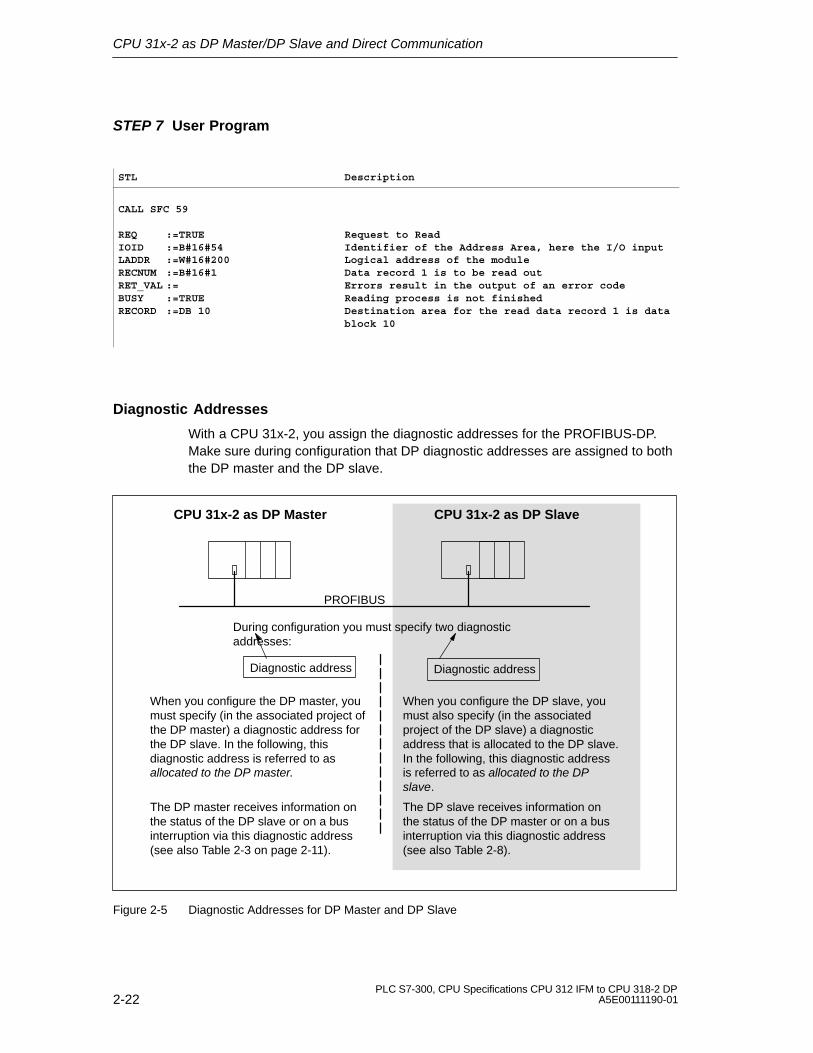
CPU 31x-2 as DP Master/DP Slave and Direct Communication
2-22PLC S7-300, CPU Specifications CPU 312 IFM to CPU 318-2 DP
A5E00111190-01
STEP 7 User Program
STL Description
CALL SFC 59
REQ :=TRUEIOID :=B#16#54LADDR :=W#16#200RECNUM :=B#16#1RET_VAL :=BUSY :=TRUERECORD :=DB 10
Request to ReadIdentifier of the Address Area, here the I/O inputLogical address of the moduleData record 1 is to be read outErrors result in the output of an error codeReading process is not finishedDestination area for the read data record 1 is datablock 10
Diagnostic Addresses
With a CPU 31x-2, you assign the diagnostic addresses for the PROFIBUS-DP.Make sure during configuration that DP diagnostic addresses are assigned to boththe DP master and the DP slave.
During configuration you must specify two diagnosticaddresses:
PROFIBUS
CPU 31x-2 as DP SlaveCPU 31x-2 as DP Master
Diagnostic address Diagnostic address
When you configure the DP master, youmust specify (in the associated project ofthe DP master) a diagnostic address forthe DP slave. In the following, thisdiagnostic address is referred to asallocated to the DP master.
When you configure the DP slave, youmust also specify (in the associatedproject of the DP slave) a diagnosticaddress that is allocated to the DP slave.In the following, this diagnostic addressis referred to as allocated to the DPslave.
The DP master receives information onthe status of the DP slave or on a businterruption via this diagnostic address(see also Table 2-3 on page 2-11).
The DP slave receives information onthe status of the DP master or on a businterruption via this diagnostic address(see also Table 2-8).
Figure 2-5 Diagnostic Addresses for DP Master and DP Slave

CPU 31x-2 as DP Master/DP Slave and Direct Communication
2-23PLC S7-300, CPU Specifications CPU 312 IFM to CPU 318-2 DPA5E00111190-01
Event Detection
Table 2-8 shows how a DP Master CPU 31x-2 recognizes operating statetransitions of a DP Slave CPU or or data transfer interrupts.
Table 2-8 Event Detection of the CPU 31x-2 as DP Slave
Event What Happens in the DP Slave
Bus interruption(short-circuit, plugdisconnected)
� OB 86 is called and a station failure reported(incoming event; diagnostic address of the DP slave assignedto the DP slave)
� on peripheral access: Call of OB 122 (Peripheral access error)
DP Master: RUN → STOP
� OB 82 is called and Module fault reported(incoming event; diagnostic address of the DP slave assigned to the DP slave) Variable OB82_MDL_STOP=1)
DP Master: STOP → RUN
� Call of OB82 with the message Module OK. (outgoing event; diagnostic address of the DP slave assigned to the DP slave) Variable OB82_MDL_STOP=0)
Evaluation in the User Program
Table 2-9 shows you how you can, for example, evaluate RUN-STOP transitions ofthe DP master in the DP slave (see Table 2-8).
Table 2-9 Evaluating RUN-STOP Transitions in the DP Master/DP Slave
In the DP Master In the DP Slave
Diagnostic Addresses Example:Master diagnostic address =1023Slave diagnostic address in the mastersystem =1022
Diagnostic Addresses Example:Slave diagnostic address =422Master diagnostic address = not relevant
CPU: RUN → STOP The CPU calls OB 82 with the followinginformation:
� OB 82_MDL_ADDR:=422
� OB82_EV_CLASS:=B#16#39(incoming event)
� OB82_MDL_DEFECT:=Module fault
Tip: The CPU’s diagnostic data buffer alsocontains this information

CPU 31x-2 as DP Master/DP Slave and Direct Communication
2-24PLC S7-300, CPU Specifications CPU 312 IFM to CPU 318-2 DP
A5E00111190-01
2.6.4 Format of the Slave Diagnostic Data
Structure of Slave Diagnostics
Byte 0Byte 1 Station Status 1 to 3Byte 2
Byte 3 Master PROFIBUS Address
Byte 4Byte 5 Low byte
High byteManufacturerIdentification
Byte 6to
Module Diagnostics
Byte x
Station Diagnostics...
.
.
.
Byte x+1toByte y
(the length depends on thenumber of address areasconfigured for transfer memory 1)
(the length depends on thenumber of address areasconfigured for transfer memory)
1 Exception: If the DP master is incorrectly configured, the DP slaveinterprets 35 configured address areas (46H).
Figure 2-6 Format of the Slave Diagnostic Data

CPU 31x-2 as DP Master/DP Slave and Direct Communication
2-25PLC S7-300, CPU Specifications CPU 312 IFM to CPU 318-2 DPA5E00111190-01
2.6.5 Station Status 1 to 3
Definition
Station status 1 to 3 provides an overview of the status of a DP slave.
Station Status 1
Table 2-10 Structure of Station Status 1 (Byte 0)
Bit Description Remedy
0 1: DP slave cannot be addressed byDP master.
� Is the correct DP address set on the DPslave?
� Bus connector plugged in?
� Does the DP slave have power?
� RS 485 Repeater setting OK?
� Execute a Reset on the DP slave.
1 1: DP slave is not ready for datainterchange.
� Wait; the DP slave is still doing its run-up.
2 1: The configuration data which theDP master sent to the DP slave donot correspond with the DP slave’sactual configuration.
� Was the software set for the right stationtype or the right DP slave configuration?
3 1: Diagnostic interrupt, generated by aRUN/STOP transition on the CPU
0: Diagnostic interrupt, generated by aSTOP/RUN transition on the CPU
� You can read out the diagnostic data.
4 1: Function is not supported, forinstance changing the DP addressat the software level.
� Check the configuring data.
5 0: This bit is always “0”. -
6 1: DP slave type does not correspondto the software configuration.
� Was the software set for the right stationtype? (parameter assignment error)
7 1: DP slave was configured by adifferent DP master to the one thatcurrently has access to it.
� Bit is always “1” when, for instance, you arecurrently accessing the DP slave via the PGor a different DP master.
The DP address of the master thatconfigured the slave is located in the“Master PROFIBUS address” diagnosticbyte.

CPU 31x-2 as DP Master/DP Slave and Direct Communication
2-26PLC S7-300, CPU Specifications CPU 312 IFM to CPU 318-2 DP
A5E00111190-01
Station Status 2
Table 2-11 Structure of Station Status 2 (Byte 1)
Bit Meaning
0 1: New parameter assignment and configuration of the DP Slave isrequired.
1 1: A diagnostic message has arrived. The DP slave cannot continueoperation until the error has been rectified (static diagnostic message).
2 1: This bit is always “1” when there is a DP slave with this DP address.
3 1: The watchdog monitor has been activated for this DP slave.
4 0: This bit is always “0”.
5 0: This bit is always “0”.
6 0: This bit is always “0”.
7 1: DP slave is deactivated, that is to say, it has been removed from thescan cycle.
Station Status 3
Table 2-12 Structure of Station Status 3 (Byte 2)
Bit Description
0
to
6
0: These bits are always “0”.
7 1: � More diagnostic messages have arrived than the DP slave canbuffer.
� The DP master cannot enter all the diagnostic messages sent by theDP slave in its diagnostic buffer.

CPU 31x-2 as DP Master/DP Slave and Direct Communication
2-27PLC S7-300, CPU Specifications CPU 312 IFM to CPU 318-2 DPA5E00111190-01
2.6.6 Master PROFIBUS Address
Definition
The DP address of the DP Master is written to the diagnostic byte MasterPROFIBUS address:
� The master that has configured the DP slave
� The master that has read and write access to the DP slave
Master PROFIBUS Address
Table 2-13 Structure of the Master PROFIBUS Address (Byte 3)
Bit Description
0 to 7 DP address of the DP master that configured the DP slave and hasread/write access to that DP slave.
FFH: DP slave was not configured by a DP master.
2.6.7 Manufacturer ID
Definition
The manufacturer identification contains a code specifying the DP slave’s type.
Manufacturer Identification
Table 2-14 Structure of the Manufacturer Identification (Bytes 4 and 5)
Byte 4 Byte 5 Manufacturer Identification for
80H 2FH CPU 315-2 DP
80H 6FH CPU 316-2 DP
80H 7FH CPU 318-2

CPU 31x-2 as DP Master/DP Slave and Direct Communication
2-28PLC S7-300, CPU Specifications CPU 312 IFM to CPU 318-2 DP
A5E00111190-01
2.6.8 Module Diagnostics
Definition
ID related diagnostics specifies in which one of the configured address areas oftransient memory an entry was made.
Byte 67 0 Bit No.
Length of ID-related diagnostic data incl. byte 6 (up to 6 bytes, depending on the number of configuredaddress areas)
Byte 7
Default and actual config. Slave CPU in STOP
Entry for the 2nd configured address areaEntry for the 3rd configured address area
Entry for the 4th configured address area
Entry for the 5th configured address area
Byte 8
Entry for the 6th to 13th configured address area
Code for module diagnosis
0 1
7 6 5 4 1
02 1
3
Entry for the 1st configured address area
Bit No.
Bit No.7 6 5 4 3
Byte 11
Entry for the 30th configured address area
Entry for the 31st configured address area
02 1 Bit No.7 6 5 4 3
Byte 802 1 Bit No.7 6 5 4 3
Byte 802 1 Bit No.7 6 5 4 3
Byte 9
Entry for the 14th to 21st configured address area
02 1 Bit No.7 6 5 4 3
Byte 10
Entry for the 22nd to 29th configured address area
02 1 Bit No.7 6 5 4 3
Entry for the 32nd configured address area
00 00 0
Default and actual configuration
Default and actual configuration
Figure 2-7 Structure of the Module Diagnosis of the CPU 31x-2

CPU 31x-2 as DP Master/DP Slave and Direct Communication
2-29PLC S7-300, CPU Specifications CPU 312 IFM to CPU 318-2 DPA5E00111190-01
2.6.9 Station Diagnostics
Definition
Device diagnostics provides details on a DP Slave. The station diagnosis beginsas of byte x and can have a maximum of 20 bytes.
Station Diagnostics
The figure below describes the structure and content of the bytes for a configuredaddress area in transfer memory.
Byte x+1 01H: Code for Diagnostic Interrupt02H: Code for Process Interrupt
Byte x +4tobyte x +7
Byte x7 0 Bit No.
Length of the station diagnosisincl. byte x (= max. 20 bytes)
Code for station diagnostics
0 0
6
Byte x+2
Byte x+3
Number of the configured addressarea in transfer memory. Valid is: Number+3(Example:CPU = 02H1. Address area = 04H2. Address area = 05H etc.)
(Always 0)
Diagnostic data (see Figure 2-9) or Interrupt data
7 0
0 0 0 0 0 0 0 0
Figure 2-8 Structure of the Station Diagnosis

CPU 31x-2 as DP Master/DP Slave and Direct Communication
2-30PLC S7-300, CPU Specifications CPU 312 IFM to CPU 318-2 DP
A5E00111190-01
As of byte x +4
The purpose of the bytes beginning with byte x+4 depends on byte x+1 (seeFigure 2-8).
Byte x+1 Contains the Code for...
Diagnostic Interrupt (01H) Hardware interrupt (02H)
The diagnostic data contains the 16 bytes ofstatus information from the CPU. Figure 2-9shows the contents of the first four bytes ofdiagnostic data. The next 12 bytes are always0.
You can freely program 4 interrupt informationbytes for the process interrupt. In STEP 7,transfer these bytes with SFC 7 “DP_PRAL”to the DP Master (refer to Chapter 2.6.10).
Bytes x+4 to x+7 for Diagnostic Interrupts
Figure 2-9 shows the structure and content of bytes x +4 to x +7 for the diagnosticinterrupt. The contents of these bytes correspond to the contents of data record 0of the diagnostic data in STEP 7 (in this case, not all bits are assigned).
Byte x+47 0 Bit No.
Byte x+5
Byte x+6
0: Operating state RUN1: Operating state STOP
0: Module OK.1: Module error
0
1
0 0 0 0
1
7 4 0
02
3 Bit No.
Bit No.7 027
0 0
0 0 00 01
ID for the address area in transfermemory (constant)
0000000
Byte x+77 0 Bit No.0 0 0 0 00 0 0
Figure 2-9 Byte x +4 to x +7 for Diagnostic and Hardware interrupt

CPU 31x-2 as DP Master/DP Slave and Direct Communication
2-31PLC S7-300, CPU Specifications CPU 312 IFM to CPU 318-2 DPA5E00111190-01
2.6.10 Interrupts
Interrupts with S7/M7 DP Master
You can trigger a process interrupt at the DP Master in the user program of a CPU31x-2 operating as DP Slave. A call of SFC 7 “DP_PRAL” triggers an OB40 in theuser program of the DP Master. SFC 7 allows you to forward interrupt informationin a DWORD to the DP master; this information can then be evaluated in OB 40 invariable OB40_POINT_ADDR. You can program the interrupt information asdesired. A detailed description of SFC 7 “DP_PRAL” can be found in the referencemanual entitled System Software S7-300/400 - System and Standard Functions.
Interrupts with Another DP Master
If you are running the CPU 31x-2 with another DP master, these interrupts arereflected in the station diagnosis of the CPU 31x-2. You must post-process therelevant diagnostic events in the DP master’s user program.
Note
When evaluating diagnostic/process interrupts with another DP Master viadevice-specific diagnostics, take into consideration:
� The DP master should be able to store the diagnostic messages, that is, theDP master should have a ring buffer in which to place these messages. If theDP master can not store diagnostic messages, only the last diagnosticmessage would be available for evaluation.
� You must scan the relevant bits in the device-related diagnostic data in youruser program at regular intervals. You must also take the PROFIBUS-DP’s buscycle time into consideration so that you can scan the bits at least once in syncwith the bus cycle time, for example.
� With an IM 308-C operating as DP Master, you cannot use process interruptsin a device-specific diagnosis because only incoming interrupts are reported,rather than outgoing interrupts.

CPU 31x-2 as DP Master/DP Slave and Direct Communication
2-32PLC S7-300, CPU Specifications CPU 312 IFM to CPU 318-2 DP
A5E00111190-01
2.7 Direct Data Exchange
As of STEP 7 V 5.x you can configure “Direct Data Exchange” for your PROFIBUSnodes. The CPU 31x-2 can take part in direct communication as the sender orreceiver.
“Direct communication” is a special communication relationship betweenPROFIBUS-DP nodes.
Principle
Direct communication is characterized by the fact that the PROFIBUS-DP nodes“listen in” to find out which data a DP slave is sending back to its DP master.Using this function the eavesdropper (receiver) can directly access changes in theinput data of remote DP slaves.
In your configuration with STEP 7, specify via respective peripheral inputaddresses the address area of the receiving station to which requested send datais fetched.
A CPU 31x-2 can be:Transmitter operating as DP SlaveReceiver operating as DP Slave or DP Master, or as CPU that is not
tied into a master system (see Figure 2-10).
Example:
Figure 2-10 shows an example of the direct communication “relationships” you canconfigure. The figure shows all DP Masters and DP Slaves as CPU 31x-2. Notethat other DP Slaves (ET 200M, ET 200X, ET 200S) can only operate astransmitters.
PROFIBUS
CPU 31x-2 asDP master
1
CPU31x-2
DP slave3
DP slave5CPU
31x-2 as DPslave 1
DP master system 1 DP master system 2
CPU 31x-2 asDP master
2
CPU31x-2 as DPslave 2
CPU31x-2 as DPslave 4
Figure 2-10 Direct Communication using CPU 31x-2

CPU 31x-2 as DP Master/DP Slave and Direct Communication
2-33PLC S7-300, CPU Specifications CPU 312 IFM to CPU 318-2 DPA5E00111190-01
2.8 Diagnosis with Direct Communication
Diagnostic Addresses
With direct communication you allocate a diagnostic address on the receiver:
PROFIBUS
CPU 31x-2 as ReceiverCPU 31x-2 as Sender
Diagnostic address
During configuration you define in thereceiver a diagnostic address that isallocated to the sender.
The receiver receives information on thestatus of the sender or on a businterruption via this diagnostic address(see also Table 2-15).
Figure 2-11 Diagnostic address for receiver with direct communication
Event Detection
Table 2-15 shows how a CPU 31x-2 operating as receiver recognizes datatransmission errors.
Table 2-15 Event Detection by CPU 31x-2 Acting as Receiver in Direct Communication
Event What Happens in the Receiver
Businterruption<FJ>(short-circuit, plugdisconnected)
� OB 86 is called and a station failure reported(incoming event; diagnostic address of the receiver, assignedto the sender)
� on peripheral access: Call of OB 122 <FJ>(Peripheral accesserror)

CPU 31x-2 as DP Master/DP Slave and Direct Communication
2-34PLC S7-300, CPU Specifications CPU 312 IFM to CPU 318-2 DP
A5E00111190-01
Evaluation in the User Program
Table 2-16 shows you how you can, for example, evaluate the station failure of thesender in the receiver (see also Table 2-15).
Table 2-16 Evaluation of the Station Failure of the Sender During Direct Communication
In the Sender In the Receiver
Diagnostic Addresses Example:<FJ>Master diagnostic address =1023<FJ>Slave diagnostic address in the master<FJ>system =1022
Diagnostic address: (Example)Diagnostic address =444
Station failure The CPU calls OB 86 with the followinginformation:
� OB 86_MDL_ADDR:=444
� OB86_EV_CLASS:=B#16#38(incoming event)
� OB86_FLT_ID:=B#16#C4 (failure of a DP station)
Tip: The CPU’s diagnostic data buffer alsocontains this information

3-1PLC S7-300, CPU Specifications CPU 312 IFM to CPU 318-2 DPA5E00111190-01
Cycle and Reaction times
Introduction
In this section, we explain what the cycle time and the response time of the S7-300consist of.
You can use the programming device to read the cycle time of your user program(see the STEP 7 online help system).
The example below shows you how to calculate the cycle time.
The response time is more important for the process. In this chapter we will showyou in detail how to calculate the response time.
In This Section
Section Contents Page
3.1 Cycle Time 3-2
3.2 Response Time 3-3
3.3 Calculation Example for Cycle Time and Response Time 3-10
3.4 Interrupt Response Time 3-14
3.5 Calculation Example for the Interrupt Response Time 3-16
3.6 Reproducibility for Delay and Watchdog Interrupt 3-16
Execution times
� for the STEP 7 instructions processed by the CPU
� for the SFCs/SFBs integrated in the CPUs
� for IEC functions you can call in STEP 7
can be found in the S7300 Instruction List
3

Cycle and Reaction times
3-2PLC S7-300, CPU Specifications CPU 312 IFM to CPU 318-2 DP
A5E00111190-01
3.1 Cycle time
Cycle Time – A Definition
The cycle time is the time that elapses during one program cycle.
Component Parts of the Cycle Time
The cycle time comprises:
Factors Remarks
Operating system execution time
Process image transfer time(PII and PIO)
See Section 3.2
User program execution time Can be calculated on the basis of the execution times of theindividual instructions (see the S7-300 Instruction List ) and aCPU-specific factor (see Table 3-3)
S7 timer (not in the case of theCPU318-2)
PROFIBUS DP See Section 3.2
Integrated functions
Communication via the MPI You configure the maximum permissible cycle load produced bycommunication in percent in STEP 7
Loading through interrupts See Sections 3.4 and 3.5
Figure 3-1 shows the component parts of the cycle time
PII
Operatingsystem
Userprogram
PIO
Interrupts
Operatingsystem
Userprogram
Figure 3-1 Component Parts of the Cycle Time

Cycle and Reaction times
3-3PLC S7-300, CPU Specifications CPU 312 IFM to CPU 318-2 DPA5E00111190-01
Extending the Cycle Time
Note that the cycle time of a user program is extended by the following:
� Time-controlled interrupt handling
� process interrupt processing (also refer to Chapter 3.4)
� Diagnostics and error handling (see also Section 3.4)
� Communication via MPI
3.2 Response Time
Response Time – A Definition
The response time is the time between detection of an input signal andmodification of an associated output signal.
Factors
The response time depends on the cycle time and the following factors:
Factors Remarks
Delay of the inputs and outputs The delay times are given in the technical specifications
� In the Module Specifications Reference Manual for thesignal modules
� In Chapter1.4.1 for the integrated I/O of the CPU 312IFM.
� In Chapter1.4.4 for the integrated inputs/outputs of theCPU 314 IFM.
Additional bus runtimes on the PROFIBUSsubnet
CPU 31x-2 DP only
Range of Fluctuation
The actual response time lies between a shortest and a longest response time.You must always reckon on the longest response time when configuring yoursystem.
The shortest and longest response times are considered below to let you get anidea of the width of fluctuation of the response time.

Cycle and Reaction times
3-4PLC S7-300, CPU Specifications CPU 312 IFM to CPU 318-2 DP
A5E00111190-01
Shortest Response Time
Figure 3-2 shows you the conditions under which the shortest response time isreached.
Operatingsystem
Userprogram
PIIThe status of the observed input changesimmediately before reading in the PII. Thechange in the input signal is therefore takenaccount of in the PII.
PIO
The change in the input signal is processedby the user program here.
The response of the user program to theinput signal change is passed on to theoutputs here.
Res
pons
e T
ime
Delay of the inputs
Delay of the outputs
Figure 3-2 Shortest Response Time
Calculation
The (shortest) response time consists of the following:
� 1 � Process image transfer time of the inputs +
� 1 �operating system execution time +
� 1 � Program execution time +
� 1 �Process image transfer time of outputs +
� Execution time of S7 timer
� Delay of the inputs and outputs
This corresponds to the sum of the cycle time and the delay of the inputs andoutputs.
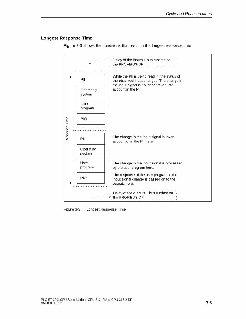
Cycle and Reaction times
3-5PLC S7-300, CPU Specifications CPU 312 IFM to CPU 318-2 DPA5E00111190-01
Longest Response Time
Figure 3-3 shows the conditions that result in the longest response time.
Operatingsystem
Userprogram
PIIWhile the PII is being read in, the status ofthe observed input changes. The change inthe input signal is no longer taken intoaccount in the PII.
PIO
The change in the input signal is takenaccount of in the PII here.
The change in the input signal is processedby the user program here.
The response of the user program to theinput signal change is passed on to theoutputs here.
Res
pons
e T
ime
Delay of the inputs + bus runtime onthe PROFIBUS-DP
Delay of the outputs + bus runtime onthe PROFIBUS-DP
Operatingsystem
Userprogram
PII
PIO
Figure 3-3 Longest Response Time

Cycle and Reaction times
3-6PLC S7-300, CPU Specifications CPU 312 IFM to CPU 318-2 DP
A5E00111190-01
Calculation
The (longest) response time consists of the following:
� 2 � Process image transfer time of inputs +
� 2 �Process image transfer time of outputs +
� 2 �Operating system execution time+
� 2 �program execution time+
� 2 �Bus runtime on the PROFIBUS-DP bus system (with CPU 31x-2 DP)
� Execution time of the S7 timer+
� Delay of the inputs and outputs
This corresponds to the sum of the double cycle time and the delay of the inputsand outputs plus the double bus runtime.
Operating System Processing Time
Table 3-1 contains all the times needed to calculate the operating systemprocessing times of the CPUs.
The times listed do not take account of
� Test functions, e.g. monitor, modify
� Functions: Load block, delete block, compress block
� Communication
Table 3-1 Operating System Processing Times of the CPUs
Sequence CPU312 IFM
CPU313
CPU314
CPU314 IFM
CPU315
CPU315-2 DP
CPU316-2 DP
CPU318-2
Cycle control 600 to1200ms
540 to1040ms
540 to1040ms
770 to1340ms
390 to820 ms
500 to1030 ms
500 to1030 ms
200 �s
Process Image Update
Table 3-2 contains the CPU times for process image updates (Process imagetransfer time). The times specified are “ideal values” which are prolonged byinterrupts or by communication of the CPU.(Process image = PI)
The time required by the CPU time for a process image update is calculated by
K + number of bytes in the PI of module rack “0”�A + number of bytes in the PI of module racks “1 to 3“�B+ number of bytes in the PI via DP �D= Process image transfer time

Cycle and Reaction times
3-7PLC S7-300, CPU Specifications CPU 312 IFM to CPU 318-2 DPA5E00111190-01
Table 3-2 Process image update of the CPUs
Components CPU312IFM
CPU313
CPU314
CPU314IFM
CPU315
CPU315-2
DP
CPU316-2
DP
CPU318-2
K Base load 162�s 142�s 142�s 147�s 109�s 10�s 10�s 20�s
A For each byte in rack“0”
14.5�s 13.3�s 13.3�s 13.6�s 10.6�s 20�s(perword)
20�s(perword)
6 �s
B For each byte in racks“1 to 3”
16.5�s 15.3�s 15.3�s 15.6�s 12.6�s 22�s(perword)
22�s(perword)
12.4�s
D For each byte in DParea for integrated DPinterface
– – – – – 12�s(perword)
12�s(perword)
1�s
User Program Processing Time:
The user program processing time is made up of the sum of the execution timesfor the instructions and the SFB/SFCs called up. These execution times can befound in the Instruction List. Additionally, you must multiply the user programprocessing time by a CPU-specific factor. This factor is listed in Table 3-3 for theindividual CPUs.
Table 3-3 CPU-specific Factors for the User Program Processing Time
Se-quence
CPU 312IFM
CPU 313 CPU 314 CPU 314IFM
CPU 315 CPU315-2DP
CPU316-2 DP
CPU318-2
Factor 1.23 1.19 1.15 1.15 1.15 1.19 1.19 1.0
S7 timers
In the case of the CPU 318-2, the updating of the S7 timers does not extend thecycle time.
The S7 Timer is updated every 10 ms.You can find out in Section 3.3 how to include the S7 timers in calculations of thecycle and response times.
Table 3-4 Updating the S7 Timers
Sequence 312 IFM 313 314 314 IFM 315 315-2DP 316-2DP
Updating the S7timers (every 10 ms)
Number ofsimultaneouslyactive S7timers � 10 �s
Number of simultaneously active S7 timers � 8 ms

Cycle and Reaction times
3-8PLC S7-300, CPU Specifications CPU 312 IFM to CPU 318-2 DP
A5E00111190-01
PROFIBUS-DP interface
In the case of the CPU 315-2 DP/316-2DP, the cycle time is typically extended by5% when the PROFIBUS-DP interface is used.
In the case of the CPU 318-2, there is no increase in cycle time when thePROFIBUS-DP interface is used.
Integrated Functions
With CPU 312-IFM and 314-IFM operation the cycle time increases by a maximumof 10% when using integrated functions. Also take into consideration a possibleinstance DB update during the cycle checkpoint.
Table 3-5 shows the update times of the instance DB at the scan cycle checkpoint,together with the corresponding SFB runtimes.
Table 3-5 Update Time and SFB Runtimes
CPU 312 IFM/314 IFM Update Time of theInstance DB at the Scan
Cycle Checkpoint
SFB Runtime
IF Frequency Measurement(SFB 30)
100 �s 220 �s
IF Counting (SFB 29) 150 �s 300 �s
IF Counting (Parallelcounter) (SFB 38)
100 �s 230 �s
IF Positioning (SFB 39) 100 �s 150 �s
Delay of the Inputs and Outputs
You must take account of the following delay times, depending on the module:
� For digital inputs: The input delay time
� For digital outputs: Negligible delay times
� For relay outputs: Typical delay times of between 10 ms and 20 ms.
The delay of the relay outputs depends, among other things, on thetemperature and voltage.
� For analog inputs: Cycle time of the analog input
� For analog outputs: Response time of the analog output

Cycle and Reaction times
3-9PLC S7-300, CPU Specifications CPU 312 IFM to CPU 318-2 DPA5E00111190-01
Bus Runtimes in the PROFIBUS Subnet
If you have used STEP 7 to configure your PROFIBUS subnet, STEP 7 calculatesthe expected normal bus cycle time. On the PG you can then view the bus cycletime of your configuration (refer to the STEP 7 User Manual).
An overview of the bus runtime is provided in Figure 3-4. In this example, weassume that each DP slave has an average of 4 bytes of data.
Bus runtime
Number of DP slaves
6 ms
4 ms
2 ms
1 2 4 8 16 32
Baud rate: 12Mbit/s
Baud rate: 1.5 Mbit/s
1 ms
3 ms
5 ms
7 ms
Min. slaveinterval
64
Figure 3-4 Overview of the Bus Runtime on PROFIBUS-DP at 1.5 Mbps and 12Mbps
Take the bus cycle time into consideration for every master when operating aPROFIBUS subnet with more than one master. That is, bus cycle time total = buscycle time � number of masters.

Cycle and Reaction times
3-10PLC S7-300, CPU Specifications CPU 312 IFM to CPU 318-2 DP
A5E00111190-01
Extending the Cycle by Nesting Interrupts
Table 3-6 shows typical extensions of the cycle time through nesting of aninterrupt. The program runtime at the interrupt level must be added to these. Ifseveral interrupts are nested, the corresponding times need to be added.
Table 3-6 Extending the Cycle by Nesting Interrupts
Interrupts 312 IFM 313 314 314 IFM 315 315-2 DP 316-2DP 318-2
Hardware<FJ>interrupt
approx.
840 �s
approx.
700 �s
approx.
700 �s
approx.
730 �s
approx.
480 �s
approx.
590 �s
approx.
590 �s
approx.
340ms
Diagnosticinterrupt
– approx.
880 �s
approx.
880 �s
approx.
1000 �s
approx.
700 �s
approx.
860 �s
approx.
860 �s
approx.
450 �s
Time–of–dayinterrupt
– – approx.
680 �s
approx.
700 �s
approx.
460 �s
approx.
560 �s
approx.
560 �s
approx.
350 �s
Delayinterrupt
– – approx.
550 �s
approx.
560 �s
approx.
370 �s
approx.
450 �s
approx.
450 �s
approx.
260 �s
Watchdoginterrupt
– – approx.
360 �s
approx.
380 �s
approx.
280 �s
approx.
220 ��
approx.
220 ��
approx.
260 �s
Programming/accesserror/programexecutionerror
– approx.
740 �s
approx.
740 �s
approx.
760 �s
approx.
560 �s
approx.
490 �s
approx.
490 �s
approx.130/ 155/285 �s
3.3 Calculation Examples for Cycle Time and Response Time
Component Parts of the Cycle Time
As a reminder: The cycle time comprises:
� process image transfer time +
� operating system processing time +
� user program processing time +
� Processing time of S7 timers
Cycle and Reaction times
3-11PLC S7-300, CPU Specifications CPU 312 IFM to CPU 318-2 DPA5E00111190-01
Sample Configuration 1
You have configured an S7-300 with the following modules on one rack:
� 1 CPU 314
� 2 SM 321 DI 32DC 24 V digital input modules (4 bytes each in the PI)
� 2 SM 322 DO 32�DC 24 V/0.5A (4 bytes each in the PI)
According to the Instruction List, the user program has a runtime of 1.5 ms.There is no communication.
Calculation
In this example, the cycle time is calculated from the following times:
� Process image transfer time
Input process image: 147 �s + 8 bytes�13.6 �s = approx. 0.26 ms
Output process image: 147 �s + 8 bytes 13.6 �s = approx. 0.26 ms
� Operating system cycle time
Cycle control: approx. 1 ms
� User program processing time:
approx. 1.5 ms CPU specific factor 1.15 = approx. 1.8 ms
� Processing time of S7 timers
Assumption: 30 S7 timers are running.
For 30 S7 timers, the one-off update takes
30 � 8 �s = 240��s.
Process image transfer time + operating system processing time + userprogram cycle time results in this time interval:
0.26 ms + 0.26 ms + 1 ms + 1.8 ms = 3.32 ms.
Since the S7 timers are called every 10 ms, a maximum of one call can bemade in this time interval, i.e. the S7 timers might increase cycle time by amaximum of 240 �s (= 0.24 ms)
The cycle time is calculated from the sum of the listed times:
Cycle time = 0.26 ms + 0.26 ms + 1 ms + 1.8 ms + 0.24 ms = 3.56 ms.
Cycle and Reaction times
3-12PLC S7-300, CPU Specifications CPU 312 IFM to CPU 318-2 DP
A5E00111190-01
Parts of the Response Time
As a reminder, the response time is formed by the sum of:
� 2 � Process image transfer time of inputs +
� 2 � Process image transfer time of outputs +
� 2 � operating system cycle time+
� 2 �program cycle time+
� Processing time of the S7 timers +
� Delay times of the inputs and outputs
Tip: Simple calculation: calculated cycle time � 2 + delay times.
Thus, for example one applies: 3.34 ms � 2 + timers the I/O modules.
Sample Configuration 2
You have configured an S7-300 with the following modules on two racks:
� 1 CPU 314
� 4 SM 321 DI 32DC 24 V digital input modules (4 bytes each in the PI)
� 3 SM 322 DO 16 DC 24 V/0.5A (2 bytes each in the PI)
� 2 SM 331 AI 8�12 bits (not in the process image)
� 2 SM 332 AI 4�12 bits (not in the process image)
User program
According to the Instruction List, the user program has a runtime of 2 ms. Bytaking into account the CPU-specific factor of 1.15, the resulting runtime is approx.2.3 ms. The user program operates up to 56 S7 timers simultaneously. Noactivities are required at the scan cycle checkpoint.
Calculation
In this example, the response time is calculated from the following times:
� Process image transfer time
Input process image: 147 �s + 16 bytes 13.6 �s = approx. 0.36 ms
Output process image: 147 �s + 6 bytes 13.6 �s = approx. 0.23 ms
� Operating system execution time
Cycle control: approx. 1 ms
� User program processing time: 2.3 ms

Cycle and Reaction times
3-13PLC S7-300, CPU Specifications CPU 312 IFM to CPU 318-2 DPA5E00111190-01
� 1. Intermediate calculation: Timebase for the calculation of S7 timerprocessing time is the sum of all times mentioned above:
2�0.36 ms (Input process image transfer time)+ 2�0.23 ms (Output process image transfer time) + 2�1 ms (Operating system cycle time) + 2�2.3 ms User program cycle time) 7.8 ms.
� Processing time of S7 timers
Time required for a single update of 56 S7 timers: 56�8 �s = 448 ��s 0.45ms.
Since the S7 timers are called every 10 ms, a maximum of one call can bemade in the cycle time, i.e. the cycle time can be increased through the S7timers by a maximum of 0.45 ms.
� 2. Intermediate calculation:The response time without I/O delay is formed bythe sum of
8.0 ms (result of the first intermediate calculation)+ 0.45 ms (S7 timer processing time) =8.45 ms.
� Delay times of the inputs and outputs
– The SM 321 The maximum delay time of the DI 32DC 24 V digital inputmodule is 4.8ms per channel.
– Output delay of the digital output module SM 322; DO 16�DC 24 V/0.5Acan be ignored.
– The SM 331; AI 8 12bit analog input module was configured for aninterference frequency suppression of 50 Hz. This yields a conversion timeof 22 ms per channel. Since 8 channels are active, the cycle time for theanalog input module is 176 ms.
– Analog output module SM 332 AO 4�12–bit was configured for ameasurement range of 0 ...10V. The conversion time is 0.8 ms per channel.Thus, 4 active channels result in a cycle time of 3.2 ms. To be added is thesettling time of 0.1 ms for ohmic loads. Thus, the response time at theanalog output is 3.3 ms.
� Response times with delay times for inputs and outputs:
� Case 1: A digital output module channel is set after a digital input signal isreceived. This results in a response time of:
Response time = 4.8 ms + 8.45 ms = 13.25 ms.
� Case 2: An analog value is fetched and an analog value is output. This resultsin a response time of:
Response time = 176 ms + 8.45 ms + 3.3 ms = 187.75 ms.

Cycle and Reaction times
3-14PLC S7-300, CPU Specifications CPU 312 IFM to CPU 318-2 DP
A5E00111190-01
3.4 Interrupt response time
Interrupt Response Time – A Definition
The interrupt response time is the time that elapses between the first occurrence ofan interrupt signal and the calling of the first instruction in the interrupt OB.
Generally valid is: High-priority interrupts are preferred. This means the interruptresponse time is increased by the program processing time of the higher-priorityinterrupt OBs and the interrupt OBs of equal priority that have not yet beenexecuted.
Calculation
The interrupt response time is calculated as follows:
Shortest interrupt response time = minimum CPU interrupt response time +
minimum interrupt response time of the signal modules +PROFIBUS-DPbus cycle time
Longest interrupt response time = maximum CPU interrupt response time +
maximum interrupt response time of the signal modules +2 PROFIBUS-DPbus cycle time
Process interrupt response time of the CPUs
Table 3-7 lists the response time of the CPUs to process interrupts (withoutcommunication).
Table 3-7 Response time of the CPUs to process interrupts
CPU Min. Max.
312 IFM 0.6 ms 1.5 ms
313 0.5 ms 1.1 ms
314 0.5 ms 1.1 ms
314 IFM 0.5 ms 1.1 ms
315 0.3 ms 1.1 ms
315-2 DP 0.4 ms 1.1 ms
316-2DP 0.4 ms 1.1 ms
318-2 0.23 ms 0.27 ms

Cycle and Reaction times
3-15PLC S7-300, CPU Specifications CPU 312 IFM to CPU 318-2 DPA5E00111190-01
Diagnostic Interrupt Response Times of the CPUs
Table 3-8 lists the diagnostic interrupt response times of the CPUs (withoutcommunication).
Table 3-8 Diagnostic Interrupt Response Times of the CPUs
CPU Min. Max.
312 IFM – –
313 0.6 ms 1.3 ms
314 0.6 ms 1.3 ms
314 IFM 0.7 ms 1.3 ms
315 0.5 ms 1.3 ms
315-2 DP 0.6 ms 1.3 ms
316-2DP 0.6 ms 1.3 ms
318-2 0.32 ms 0.38 ms
Signal Modules
The response time of signal modules to process interrupts is calculated as follows:
� Digital input modules
Process interrupt response time = internal interrupt processing time + Inputdelay
You will find the times in the data sheet for the individual analog input module.
� Analog input modules
Process interrupt response time = internal interrupt processing time +Conversion time
The internal interrupt preparation time for the analog input modules is negligible.The conversion times can be found in the data sheet for the individual digitalinput modules.
The diagnostic interrupt response time of the signal modules is the time thatelapses between the detection of a diagnostic event by the signal module and thetriggering of the diagnostics interrupt by the signal module. This time is negligible.
Process interrupt processing
process interrupts are processed at the call of interrupt OB40. Higher-priorityinterrupts interrupt hardware interrupt processing, the I/O is accessed directly atthe time of instruction execution. After the process interrupt has been processed,cyclic program processing continues, or lower-/higher-priority interrupt OBs arecalled and processed.

Cycle and Reaction times
3-16PLC S7-300, CPU Specifications CPU 312 IFM to CPU 318-2 DP
A5E00111190-01
3.5 Calculation Example for the Interrupt Response Time
Parts of the Interrupt Response Time
As a reminder: The process interrupt response time is formed by:
� Response time of the CPU to process interrupt and
� the response time of the signal module to process interrupt.
Example: Your S7-300 assembly consists of a CPU 314 and four digital modules.One digital input module is the SM 321; DI 16�DC 24V; with hardware/diagnosticinterrupt configuration. In your CPU and SM configuration you have enabled onlyprocess interrupt. You decided not to use time-controlled processing, diagnosticsor error handling. You configured an input delay of 0.5 ms for the digital inputmodule. No activities are necessary at the scan cycle checkpoint. There is nocommunication via the MPI.
Calculation
In this example, the response time to process interrupt is calculated from followingtimes:
� Response time of CPU 314 to process interrupt: approx. 1.1 ms
� Process interrupt response time of SM 321; DI 16�DC 24V:
– Internal interrupt preparation time:0.25 ms
– Input delay 0.5 ms
The process interrupt response time is formed by the sum of all specified times:
Process interrupt response time = 1.1 ms + 0.25 ms + 0.5 ms = approx. 1.85 ms.
This calculated process interrupt response time represents the time expiringbetween an incoming signal at the digital input and the first instruction in OB40.
3.6 Reproducibility of Delay and Watchdog Interrupts
Definition of Reproducibility
Delay Interrupt:
The interval between the call-up of the first instruction in the OB and theprogrammed time of the interrupt.
Watchdog Interrupt:
The fluctuation of the time interval between two successive call-ups, measured ineach case between the first instruction in the OB.

Cycle and Reaction times
3-17PLC S7-300, CPU Specifications CPU 312 IFM to CPU 318-2 DPA5E00111190-01
Reproducibility
Table 3-9 lists reproducibility of the delay and watchdog interrupts of the CPUs(without communication).
Table 3-9 Reproducibility of the Delay and Watchdog Interrupts of the CPUs
CPU Reproducibility
Delay Interrupt Watchdog Interrupt
314 approx. –1/+0.4 ms approx. �0.2 ms
314 IFM approx. –1/+0.4 ms approx. �0.2 ms
315 approx. –1/+0.4 ms approx. �0.2 ms
315-2 DP approx. –1/+0.4 ms approx. �0.2 ms
316-2DP approx. –1/+0.4 ms approx. �0.2 ms
318-2 approx. –0.8/+0.38 ms approx. �0.04 ms

Cycle and Reaction times
3-18PLC S7-300, CPU Specifications CPU 312 IFM to CPU 318-2 DP
A5E00111190-01

4-1PLC S7-300, CPU Specifications CPU 312 IFM to CPU 318-2 DPA5E00111190-01
CPU Function, depending on CPU andSTEP 7 Version
In this chapter we describe the functional differences between the various CPUversions.
These differences are determined by
� CPU performance characteristics (especially CPU 318-2) compared to otherCPUs
� the functionaliy of CPUs described in this manual in comparison to previousversions.
Section Contents Page
4.1 Differences between CPU 318-2 and CPUs 312 IFM to 316-2 DP 4-2
4.2 Differences of CPUs 312 IFM to 318 to previous versions 4-6
4

CPU Function, depending on CPU and STEP 7 Version
4-2PLC S7-300, CPU Specifications CPU 312 IFM to CPU 318-2 DP
A5E00111190-01
4.1 Differences between CPU 3182 and CPUs 312 IFM to 3162 DP
4 rechargeable batteries for 318-2
CPU 318-2 CPUs 312IFM to 316-2DP
4 accumulators 2 accumulators
The following table shows you what to watch for if you want to use an STL userprogram of a CPU 312IFM to a CPU 316-2DP for the CPU 318-2.
Instructions User Program from the CPU 312IFM to 316-2DP for theCPU 318
Double integer math(+I, –I, *I, /I;+D, –D, *D, /D,MOD;+R, –R, *R, /R)
The CPU 318 transfers the contents of accumulators 3 and 4to accumulators 2 and 3 after these operations.
If accumulator 2 is evaluated in the (accepted) user program,you now receive incorrect values with the CPU 318-2because the value has been overwritten by the contents ofaccumulator 3.
Configuration
From 312 IFM to 316-2 DP CPUs, the CPU 318-2 “imports” only projects createdwith STEP 7 V 5.x.
You cannot operate programs containing FM or CP (SDB 1xxx) configuration data(e.g. FM 353/354) in a CPU 318-2!In this case, the respective project needs to be edited accordingly or recreated.
Starting a Timer in the User Program
The accumulator register in CPU 318–2 must contain a number in BCD formatwhen starting a timer in your user program (e.g. with SI T).
Force
The differences of force operations are described in Chapter 1.3.1.
Loading the User Program to the Memory Card
CPU 318-2 CPUs 312IFM to 316-2DP
... using the PD function Load UserProgram
... using the PD function Copy RAM ToROM or Load User Program

CPU Function, depending on CPU and STEP 7 Version
4-3PLC S7-300, CPU Specifications CPU 312 IFM to CPU 318-2 DPA5E00111190-01
System ID (only CPU 318-2)
In the object properties of the ”General” tab, you can assign a system ID whenconfiguring your CPU. This ID can be evaluated in the CPU user program (alsorefer to the STEP 7 Online Help relating to the “General” tab).
MPI Addressing
CPU 318-2 CPUs 312IFM to 316-2DP
The CPU addresses the MPI nodes within itsconfiguration (FM/CP) via the module startaddress.
If FM/CP are in the central configuration of anS7–300 with their own MPI address, the CPU formsits own communication bus (via the backplane bus)with the FM/CP, separate from the other subnets.The MPI address of the FM/CP is no longerrelevant for the nodes of other subnets.Communication to the FM/CP takes place via theCPU MPI address.
The CPUs address the MPI nodes within theirconfiguration via the MPI address.
If FM/CP are in the central configuration of anS7–300 with their own MPI address, the FM/CPand CPU MPI nodes are in the same CPU subnet.
Your S7-300 structure includes an FM/CP addressed via MPI. You want to replacethe CPU 312 IFM ... 316 with a CPU 318-2. An example is shown in Figure 4-1,Page 4-4.

CPU Function, depending on CPU and STEP 7 Version
4-4PLC S7-300, CPU Specifications CPU 312 IFM to CPU 318-2 DP
A5E00111190-01
OP 25RS 485repeater
S7-300 S7-300
S7-300
S7-300 with CPU 316
OP 25
PG
PG
FM FM
The CPU 316 is replacedwith a CPU 318-2
FM
Figure 4-1 Sample Configuration
After the CPUs have been swapped, you must proceed as follows (based on theabove example):
� Replace the CPU 316 with the CPU 318-2 in the STEP 7 project.
� Reconfigure the operator panel/programming device. That means: Reassign thecontrols and start address (= MPI address of CPU 318-2 and the respective FMslot)
� Reconfigure the configuration data for the FM/CP to be loaded onto the CPU.
This is necessary to ensure that the FM/CP in this configuration remain accessibleto the operator panel/programming device.
Inserting and Removing a Memory Card (FEPROM)
If you remove a Memory Card and insert a card in with identical content in POWEROFF state (CPU is not buffered), the result after POWER ON is:
CPU 318-2 CPUs 312IFM to 316-2DP
The CPU 318-2 goes into STOP mode andrequest a memory reset.
The CPU switches to the mode it was inprior to POWER OFF, i.e. RUN or STOP.
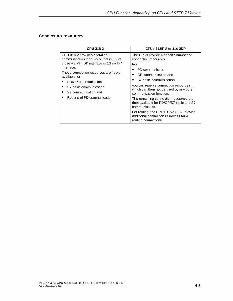
CPU Function, depending on CPU and STEP 7 Version
4-5PLC S7-300, CPU Specifications CPU 312 IFM to CPU 318-2 DPA5E00111190-01
Connection resources
CPU 318-2 CPUs 312IFM to 316-2DP
CPU 318-2 provides a total of 32communication resources, that is, 32 ofthose via MPI/DP interface or 16 via DPinterface.
Those connection resources are freelyavailable for
� PD/OP communication
� S7 basic communication
� S7 communication and
� Routing of PD communication
The CPUs provide a specific number ofconnection resources.
For
� PD communication
� OP communication and
� S7 basic communication
you can reserve connection resourceswhich can then not be used by any othercommunication function.
The remaining connection resources arethen available for PD/OP/S7 basic and S7communication.
For routing, the CPUs 315-/316-2 provideadditional connection resources for 4routing connections.

CPU Function, depending on CPU and STEP 7 Version
4-6PLC S7-300, CPU Specifications CPU 312 IFM to CPU 318-2 DP
A5E00111190-01
4.2 The Differences Between the CPUs 312 IFM to 318 andTheir Previous Versions
Memory Cards and Backing Up Firmware on Memory Card
As of the following CPUs:
CPU Order No. As of Version
Firmware Hardware
CPU 313 6ES7 313-1AD03-0AB0 1.0.0 01
CPU 314 6ES7 314-1AE04-0AB0 1.0.0 01
CPU 315 6ES7 315-1AF03-0AB0 1.0.0 01
CPU 315-2 6ES7 315-2AF03-0AB0 1.0.0 01
CPU 316-2 6ES7 316-1AG00-0AB0 1.0.0 01
You can:
� Insert the 16 bit-wide memory cards:
256 Kbyte FEPROM 6ES7 951-1KH00-0AA0
1 Mbyte FEPROM 6ES7 951-1KK00-0AA0
2 Mbyte FEPROM 6ES7 951-1KL00-0AA0
4 Mbyte FEPROM 6ES7 951-1KM00-0AA0
� Back up the CPU firmware on memory card

CPU Function, depending on CPU and STEP 7 Version
4-7PLC S7-300, CPU Specifications CPU 312 IFM to CPU 318-2 DPA5E00111190-01
MPI Addressing
You Have a CPU as of Order Number and Version:
Your CPU version and order number is lowerthan the following:
6ES7312-5AC01-0AB0, version 01
6ES7313-1AD02-0AB0, version 01
6ES7314-1AE03-0AB0, version 01
6ES7314-5AE02-0AB0, version 01
6ES7315-1AF02-0AB0, version 01
6ES7315-2AF02-0AB0, version 01
6ES7316-1AG00-0AB0, version 01 –
and STEP 7 V4.02 or later and STEP 7 < V4.02
The CPU accepts the MPI addresses configured byyou in STEP 7 for the relevant CP/FM in an S7300 or automatically determines the MPI address of theCP/FM in an S7-300 on the pattern MPI addr. CPU; MPI addr.+1 MPI addr.+2 etc.
The CPU automatically establishes the MPIaddress of the CP/FM in an S7–300 on the pattern MPI addr. CPU; MPI addr.+1 MPI addr.+2etc.
MPIaddr.
MPIaddr.“x”
MPIaddr.“z”
CPU CP CP
MPIaddr.
MPIaddr.+1
MPIaddr.+2
CPU CP CP
MPI with 19.2 Kbps
With STEP 7 as of V4.02 you can set a transmission rate for the MPI of 19.2 Kbps.
The CPUs support 19.2 Kbps as of the following order numbers:
6ES7312-5AC01-0AB0, version 016ES7313-1AD02-0AB0, version 016ES7314-1AE03-0AB0, version 016ES7314-5AE02-0AB0, version 016ES7315-1AF02-0AB0, version 016ES7315-2AF02-0AB0, version 01

CPU Function, depending on CPU and STEP 7 Version
4-8PLC S7-300, CPU Specifications CPU 312 IFM to CPU 318-2 DP
A5E00111190-01
CPU 315-2 DP
CPU 315-2 DP � 6ES7 315-2AF03-0AB0and STEP 7 < V 5.x
as of 6ES7315-2AF03-0AB0 andSTEP 7 as of V 5.x
Direct communication No Yes
Equidistance No Yes
Activation/deactivation of DPslaves
No Yes
Routing No Yes
Reading out of slavediagnosis
See Figure 2-1 on page 2-8 See Figure 2-2 on page 2-9
Connection resources
From CPU Order No. As of Version
Firmware Hardware
CPU 312 IFM 6ES7 312-5AC02-0AB0 1.1.0 01
CPU 313 6ES7 313-1AD03-0AB0 1.1.0 01
CPU 314 6ES7 314-1AE04-0AB0 1.1.0 01
CPU 314 IFM 6ES7 314-5AE03-0AB0 1.1.0 01
CPU 314 IFM 6ES7 314-5AE10-0AB0 1.1.0 01
CPU 315 6ES7 315-1AF03-0AB0 1.1.0 01
CPU 315-2 DP 6ES7 315-2AF03-0AB0 1.1.0 01
CPU 316-2 DP 6ES7 316-2AG00-0AB0 1.1.0 01
... can be reserved for PD communication, OP communication and S7 basiccommunication.In this case, the free communication resources are available for PD/OP/S7 basicor S7 communication (see also Chapter 1.2).
CPU versions earlier than those referred to above provide a fixed number ofconnection resources for the applicable communication functions.

CPU Function, depending on CPU and STEP 7 Version
4-9PLC S7-300, CPU Specifications CPU 312 IFM to CPU 318-2 DPA5E00111190-01
New SFBs and SFCs in CPU 318-2
FunctionBlock
Application Execution timein �s
See...
SFB 52
SFB 53
Fetching data records to a DP Slave
Fetching data records to a DP Slave
Initial call 221
Intermediate call 111
Final call 158
Initial call 284
Second call 110
Online help Standard andSystem functionsin STEP 7
SFB 54 Receiving interrupts from a DP Slave
(not for I/O-dependent
OBs,MODE 1, OB1)
integrated DP interface,
Final call 110
90
(MODE 1, OB 40, 83, 86)
(OB 55 to OB 57, OB 82)
(central peripherals,
MODE 1, OB 40, OB 82)
170
176
140

CPU Function, depending on CPU and STEP 7 Version
4-10PLC S7-300, CPU Specifications CPU 312 IFM to CPU 318-2 DP
A5E00111190-01
FunctionBlock
See...Execution timein �s
Application
SFC 100* Setting TOD and TOD Status MODE 1 274
MODE 2 84
MODE 3 275
Online helpStandardandSystem-
SFC 105*
Reading dynamic system resources
MODE 0 117-1832MODE 1 138-2098
MODE 2 139-1483
functions inSTEP 7
SFC 106
Releasing dynamic systemresources
MODE 3 140-2128
MODE 1 123-1376MODE 2 126-1334
SFC 107
resources
Creating block related messages
MODE 2 126-1334
MODE 3 125-1407
Initial call 257
SFC 108
including an acknowledgementfunction
Creating block related messages
without acknowledgement function
Empty call 101
Initial call 271
Empty call 115
* MODE 0: Depending on the size of the target area SYS_INST and the number of system resources still to be fetched. MODE 1 and 2: Depends on the number of active messages (occupied system resources).
MODE 3: Depends on the number of active messages (occupied system resources) andthe number of instances used with the CMP_ID to be found.

CPU Function, depending on CPU and STEP 7 Version
4-11PLC S7-300, CPU Specifications CPU 312 IFM to CPU 318-2 DPA5E00111190-01
Description of Diverse SFB Execution Times
The BUSY output parameter indicates the current job status.
Initial call: Job starts with the execution, d. h. BUSY status is toggled from 0 to 1.
Intermediate call: The job is being executed, d. h. BUSY retains 1 status.
Final call: The job was executed, d. h. BUSY status is reset from 1 to 0.
Description of Diverse SFC Execution Times
Configure the desired operating mode in your SFCs modes. The significance of aspecific mode depends on the respective function block. For details please refer tothe Online Help on Standard and System Functions in STEP 7.
Consistent User Data
If you want to download consistent user data areas (I/O area with full lengthconsistency) to a DP system, note the following:
CPU 315–2 DPCPU 316–2 DPCPU 318–2 DP
(Firmware Version < 3.0)
CPU 318–2 DP (Firmware Version > 3.0)
Consistent user data are not updated automatically, even ifthey exist in the process image.
SFC14 and SFC 15 are required forreading/writing consistent user data.
You can select whether or not to update thisarea, provided the address area of consistentuser data exists in the process image.
You can also use SFC14 and SFC 15 to readand write consistent data.
User data areas can also be accessed directly (e.g. L PEW... T PAW...).

CPU Function, depending on CPU and STEP 7 Version
4-12PLC S7-300, CPU Specifications CPU 312 IFM to CPU 318-2 DP
A5E00111190-01

5-1PLC S7-300, CPU Specifications CPU 312 IFM to CPU 318-2 DPA5E00111190-01
Tips and Tricks
Tip on the Parameter “Monitoring time for ...” in STEP 7
Configure the parameters for “Monitoring time
� for parameter download to module”
� ready message by module”
the highest values if you are not certain of the times required on the S7-300.
CPU 31x-2DP is DP Master CPU 318-2 is DP Master
You can also set power-up time monitoringfor the DP slaves with the “Transfer ofparameters to modules” parameter.
You can set power-up time monitoring forthe DP slaves with both of the aboveparameters.
This means that the DP slaves must be powered up and configured by the CPU (as DPmaster) in the set time.
FM in a Distributed Configuration in an ET 200M (CPU 31x-2 is DP Master)
If you operate an FM 353/354/355 in an ET 200M with IM 153-2 and remove andreinsert the FM in ET 200M, you must perform a cold restart (power off/on) in theET 200M.Reason: The CPU does not rewrite the parameters to the FM unless the ET200Mis initialized with “POWER ON”.
The Retentive Feature of Data Blocks
You must note the following for the retentivity of data areas in data blocks:
5
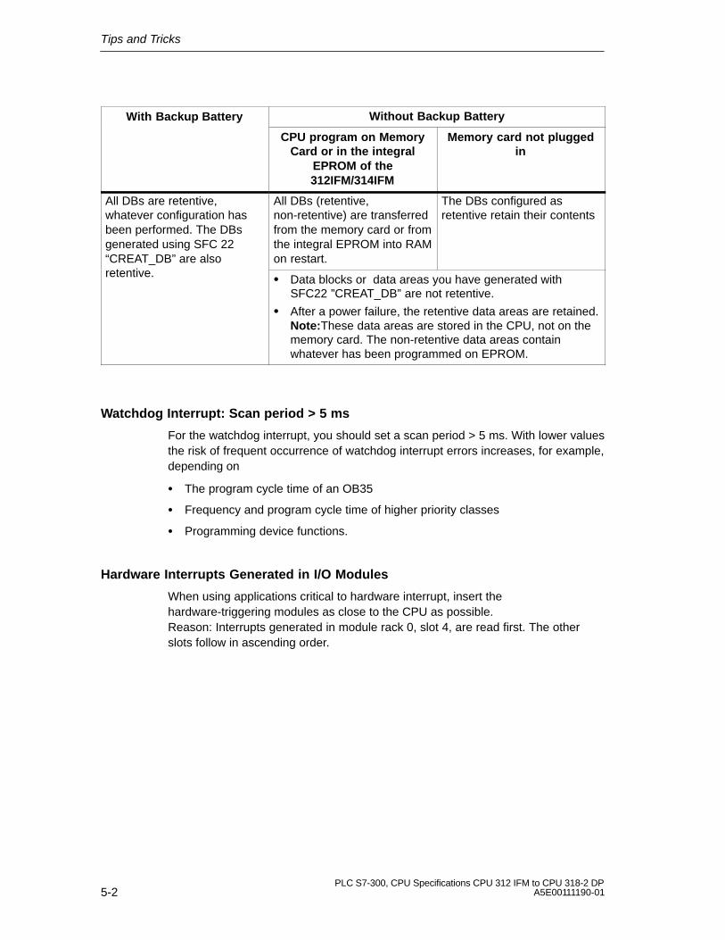
Tips and Tricks
5-2PLC S7-300, CPU Specifications CPU 312 IFM to CPU 318-2 DP
A5E00111190-01
With Backup Battery Without Backup Battery
CPU program on MemoryCard or in the integral
EPROM of the312IFM/314IFM
Memory card not pluggedin
All DBs are retentive,whatever configuration hasbeen performed. The DBsgenerated using SFC 22“CREAT_DB” are also
All DBs (retentive,non-retentive) are transferredfrom the memory card or fromthe integral EPROM into RAMon restart.
The DBs configured asretentive retain their contents
retentive.� Data blocks or data areas you have generated with
SFC22 ”CREAT_DB” are not retentive.
� After a power failure, the retentive data areas are retained.Note:These data areas are stored in the CPU, not on thememory card. The non-retentive data areas containwhatever has been programmed on EPROM.
Watchdog Interrupt: Scan period > 5 ms
For the watchdog interrupt, you should set a scan period > 5 ms. With lower valuesthe risk of frequent occurrence of watchdog interrupt errors increases, for example,depending on
� The program cycle time of an OB35
� Frequency and program cycle time of higher priority classes
� Programming device functions.
Hardware Interrupts Generated in I/O Modules
When using applications critical to hardware interrupt, insert thehardware-triggering modules as close to the CPU as possible. Reason: Interrupts generated in module rack 0, slot 4, are read first. The otherslots follow in ascending order.

Tips and Tricks
5-3PLC S7-300, CPU Specifications CPU 312 IFM to CPU 318-2 DPA5E00111190-01
CPU 312 IFM and 314 IFM: Erasing the integrated EPROM
If you wish to erase the contents of the integrated EPROM, proceed as follows:
1. Open a window with an Online view of the opened project via menu commandView � Online, or
open the Online nodes window per click on the Online nodes in the functionbar, or select the menu item PLC � Show online nodes.
2. Select the MPI number of the target CPU (double-click).
3. Select the Function Block container.
4. Select the menu item Edit� Mark all.
5. Then select the menu item File � Delete, or press the DEL key. This deletes allthe selected blocks from the target memory.
6. Select the MPI number of the target CPU.
7. Select the menu item PLC � Copy RAM to ROM.
This command deletes all blocks online and overwrites the EPROM with the blankcontents of the RAM.
SFB “DRUM” - Reversed Bytes in Output Parameter OUT-WORD
With the SFB “DRUM”, the following CPUs return the value with reversed bytes onthe output parameter OUT_WORD.
CPU 312 IFM up to 6ES7312-5ACx2-0AB0, firmware V 1.0.0CPU 313 up to 6ES7313-1AD03-0AB0, firmware V 1.0.0CPU 314 up to 6ES7314-1AEx4-0AB0, firmware V 1.0.0CPU 314 IFM up to 6ES7314-5AEx3-0AB0; firmware V 1.0.0CPU 315 up to 6ES7315-1AF03-0AB0, firmware V 1.0.0CPU 315-2 DP up to 6ES7315-2AFx2-0AB0,CPU 316 up to 6ES7316-1AG00-0AB0
The result is the following assignment, with reference to output parameter OUTj,0�j�15:
OUTj, 0�j�15:
7 6 0
j = 7 .... 0
5 4 3 2 1OUT_WORD
15 14 813 12 1110 9
j = 15 .... 8

Tips and Tricks
5-4PLC S7-300, CPU Specifications CPU 312 IFM to CPU 318-2 DP
A5E00111190-01

A-1PLC S7-300, CPU Specifications CPU 312 IFM to CPU 318-2 DPA5E00111190-01
Standards, Certificates and Approvals
Introduction
This Appendix provides the following information on the S7-300 modules andcomponents:
� The most important standards and criteria met by S7-300 and
� Approvals that have been granted for the S7-300.
IEC 1131
The S7-300 programmable controller meets the requirements and criteria tostandard IEC 1131, Part 2.
CE Symbol
Our products meet the requirements and protection guidelines of the following ECDirectives and comply with the harmonized European standards (EN) issued in theOfficial Journal of the European Communities with regard to programmablecontrollers:
� 89/336/EEC “Electromagnetic Compatibility” (EMC Directive)
� 73/23/EEC “Electrical Equipment Designed for Use between Certain VoltageLimits” (Low-Voltage Directive)
The declarations of conformity are held at the address below, where they can beobtained if and when required by the respective authorities:
Siemens AktiengesellschaftAutomation Group A&D AS RD 4P.O. Box 1963D-92209 Amberg Federal Republic of Germany
A
Standards, Certificates and Approvals
A-2PLC S7-300, CPU Specifications CPU 312 IFM to CPU 318-2 DP
A5E00111190-01
EMC Guidelines
SIMATIC products are designed for industrial use.
Area of Application Requirements:
Emittedinterference
Immunity
Industry EN 50081-2 : 1993 EN 50082-2 : 1995
If you use the S7-300 in residential areas, you must ensure emission of radiointerference complies with Limit Class B as per EN 55011.
The following measures can be taken to achieve compliance with Limit Class B:
� Install the S7-300 in an earthed control/switch cabinet
� Fit filters to supply lines
UL Recognition
UL Recognition MarkUnderwriters Laboratories (UL) toUL standard 508, Report 116536
CSA Certification
CSA-Certification-MarkCanadian Standard Association (CSA) toStandard C22.2 No. 142, File No. LR 48323
FM Approval
FM Approval to Factory Mutual Approval Standard Class Number 3611, Class I,Division 2, Group A, B, C, D.
!Warning
Personal injury or property damage can result.
In hazardous areas, personal injury or property damage can result if you withdrawany connectors while an S7-300 is in operation.
Always isolate the S7-300 in hazardous areas before withdrawing connectors.

Standards, Certificates and Approvals
A-3PLC S7-300, CPU Specifications CPU 312 IFM to CPU 318-2 DPA5E00111190-01
PNO
CPU Certificate No. As ...
DP Master DP Slave
315-2 DP Z00349 Z00258
316-2DP Yes * Yes *
318-2 Yes * Yes *
* Number was not available at time of going to press

Standards, Certificates and Approvals
A-4PLC S7-300, CPU Specifications CPU 312 IFM to CPU 318-2 DP
A5E00111190-01

B-1PLC S7-300, CPU Specifications CPU 312 IFM to CPU 318-2 DPA5E00111190-01
Dimensioned Drawings
Introduction
This appendix contains the dimensioned drawings of S7-300 CPUs. Thespecifications in these drawings are required of you for dimensioning your S7-300assembly. The dimensioned drawings of the other S7-300 modules andcomponents are contained in the Module Specifications Reference Manual.
CPU 312 IFM
Figure B-1 shows the dimensioned drawing of CPU 312IFM.
130
12080
43 23
125
130
9 25
195 with front door open
Figure B-1 Dimensioned Drawing of the CPU 312 IFM
B
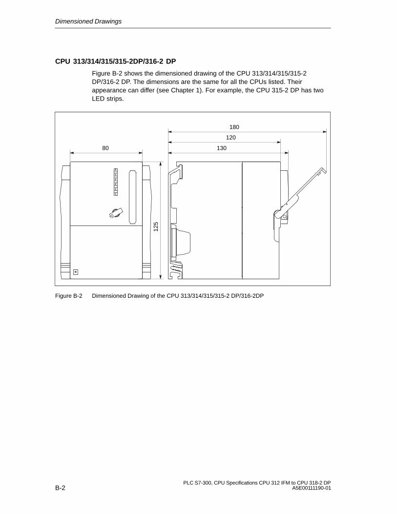
Dimensioned Drawings
B-2PLC S7-300, CPU Specifications CPU 312 IFM to CPU 318-2 DP
A5E00111190-01
CPU 313/314/315/315-2DP/316-2 DP
Figure B-2 shows the dimensioned drawing of the CPU 313/314/315/315-2DP/316-2 DP. The dimensions are the same for all the CPUs listed. Theirappearance can differ (see Chapter 1). For example, the CPU 315-2 DP has twoLED strips.
125
130
120
180
80
Figure B-2 Dimensioned Drawing of the CPU 313/314/315/315-2 DP/316-2DP

Dimensioned Drawings
B-3PLC S7-300, CPU Specifications CPU 312 IFM to CPU 318-2 DPA5E00111190-01
CPU 318-2
Figure B-3 shows the dimensioned drawing of the CPU 318-2, front view. The sideview is illustrated in Figure B-2
125
160
Figure B-3 Dimensioned Drawing of the CPU 318-2

Dimensioned Drawings
B-4PLC S7-300, CPU Specifications CPU 312 IFM to CPU 318-2 DP
A5E00111190-01
CPU 314 IFM, Front View
Figure B-4 shows the dimensioned drawing of CPU 314IFM, front view. The sideview is shown in Figure B-5.
125
160
Figure B-4 Dimensioned Drawing of the CPU 314 IFM, Front View

Dimensioned Drawings
B-5PLC S7-300, CPU Specifications CPU 312 IFM to CPU 318-2 DPA5E00111190-01
CPU 314 IFM, Side View
Figure B-5 shows the dimensioned drawing of the CPU 314 IFM, side view.
130
120
180
Figure B-5 Dimensioned Drawing of the CPU 314 IFM, Side View

Dimensioned Drawings
B-6PLC S7-300, CPU Specifications CPU 312 IFM to CPU 318-2 DP
A5E00111190-01

C-1PLC S7-300, CPU Specifications CPU 312 IFM to CPU 318-2 DPA5E00111190-01
List of Abbreviations
Abbrevia-tions
Description
STL Statement List (programming language representation in STEP 7)
CP Communication processor
CPU Central processing unit
DB Data block
FB Function block
FC Function
FM Function module
GD Global data communication
IM Interface module
IP Intelligent I/O
LAD Ladder logic (programming language representation in STEP 7)
FO Fiber-optic cable
M Chassis ground
MPI Multipoint Interface
OB Organization block
OP Operator panel
PIO Output process image
PII Input process image
PG Programming device
PS Power supply
SFB System function block
SFC System function
SM Signal module
C

List of Abbreviations
C-2PLC S7-300, CPU Specifications CPU 312 IFM to CPU 318-2 DP
A5E00111190-01

Glossary-1PLC S7-300, CPU Specifications CPU 312 IFM to CPU 318-2 DPA5E00111190-01
Glossary
Accumulator
Accumulators are registers in the � CPU. They are an intermediate memory forloading, transfer, compare, calculation and conversion operations.
Address
An address is an ID for a specific operand or operand area, for example: Input I12.1; memory word MW 25, data block DB 3).
Analog module
Analog modules convert process values (e.g. temperature) into digital values, sothat they can be processed by the central processing unit, or convert digitalvalues into analog manipulated variables.
Automation system
An SIMATIC S7 automation system is a � programmable logic controller.
Backplane bus
The backplane bus is a serial data bus over which the modules communicateand over which the necessary power is supplied to the modules. The connectionbetween the modules is established by bus connectors.
Backup battery
The backup battery ensures that the� user program in the � CPU is saved inthe event of a power failure and that defined data areas, memory bits, timers andcounters are retentive.

Glossary
Glossary-2PLC S7-300, CPU Specifications CPU 312 IFM to CPU 318-2 DP
A5E00111190-01
Backup memory
Backup memory ensures buffering of CPU memory areas � CPU, using no battery. A configurable number of timers, counters, memoriesand data bytes (retentive timers, counters, memories and data bytes) is backedup.
Bit memory
Memory bits are objects of � CPU system memory, used for storingintermediate results. They can be accessed in units of a bit, byte, word orDWORD.
Bus
A bus is a communication medium connecting several nodes. Data transmissioncan be serial or parallel across electrical conductors or fiber-optic cables.
Bus segment
A bus segment is a self-contained section of a serial bus system. Bus segmentsare interconnected using repeaters.
Chassis ground
Chassis ground is the totality of all the interconnected inactive parts of a piece ofequipment on which a hazardous touch voltage cannot build up even in the eventof a fault.
Clock memories
Memories that can be used for clocking purposes in the user program (1 memorybyte).
Note
Note in the case of S7-300 CPUs that the clock memory byte is not exceeded inthe user program.

Glossary
Glossary-3PLC S7-300, CPU Specifications CPU 312 IFM to CPU 318-2 DPA5E00111190-01
Code block
A SIMATIC S7 code block contains part of the STEP 7 user program. (Incontrast: � data block only contains data.)
Compress
The programming device online function “Compress” is used to align all validblocks contiguously in the RAM of the CPU at the start of the user memory. Thiseliminates all gaps which arose when blocks were deleted or modified.
Communication processor
Communication processors are modules for point-to-point and bus links.
Configuration
Assignment of modules to racks/slots and (e.g. for signal modules) addresses.
Consistent data
Data whose contents are related and which should not be separated are knownas consistent data.
For example, the values of analog modules must always be handled consistently,that is the value of an analog module must not be corrupted by reading it out attwo different times.
Counter
Counters are integrated in � CPU system memory. The content of the “countercells” can by modified by STEP 7 instructions (e.g. count up/down).
CP
� Communication processor
CPU
Central processing unit of the S7 programmable controller with open andclosed-loop control systems, memory, operating system and interface forprogramming device.

Glossary
Glossary-4PLC S7-300, CPU Specifications CPU 312 IFM to CPU 318-2 DP
A5E00111190-01
Cycle time
The cycle time represents the time � a CPU requires for a single � userprogram execution.
Data block
Data blocks (DB) are data areas in the user program which contain user data.Global data blocks can be accessed by all code blocks while instance datablocks are assigned to a specific FB call.
Data, static
Static data is data which can only be used within a function block. The data issaved in an instance data block belonging to the function block. The data storedin the instance data block is retained until the next function block call.
Data, temporary
Temporary data is local data of a block which is stored in the L stack duringexecution of a block and which is no longer available after execution.
Delay Interrupt
� Interrupt, Delay
Device master file
A Device Master File (GSD -file) contains all slave-specific characteristics data.Standard EN 50170,Volume 2, PROFIBUS, specifies the GSD file format.
Diagnostics
� System diagnostics
Diagnostic Interrupt
Modules with diagnostic function use diagnostic interrupts to report detectederrors to the � CPU.

Glossary
Glossary-5PLC S7-300, CPU Specifications CPU 312 IFM to CPU 318-2 DPA5E00111190-01
Diagnostic buffer
The diagnostic buffer is a buffered memory area in the CPU in which diagnosticevents are stored in the order of their occurrence.
DP Master
A � master which behaves in accordance with EN 50170, Part 3 is known as aDP master.
DP Slave
A � DP Slave is operated on a PROFIBUS bus system, using thePROFIBUS-DP protocol and behaves in accordance with EN 50170, Part 3.
Equipotential bonding
Electrical connection (equipotential bonding conductor) which gives the bodies ofelectrical equipment and external conducting bodies the same or approximatelythe same potential, in order to prevent disturbing or dangerous voltages frombeing generated between these bodies.
Error display
Error display is one of the possible responses of the operating system to �runtime error. Other possible reactions are: � Error response in the userprogram, CPU STOP status.
Error handling via OB
If the operating system detects a specific error (e.g. an access error with STEP7), it calls the organization block (error OB) which is provided for this event andwhich specifies the subsequent behavior of the CPU.
Error response
Reaction to a � runtime error. The operating system can react as follows:Switching the PLC to STOP, call of an OB in which the user can program aspecific reaction, or display of the error.
External power supply
Power supply for signal/function modules and the connected hardware I/O.

Glossary
Glossary-6PLC S7-300, CPU Specifications CPU 312 IFM to CPU 318-2 DP
A5E00111190-01
FB
� Function block
FC
� Function
Flash EPROM
FEPROMs are the same as electrically erasable EEPROMS in that they canretain data in the event of a power failure, but they can be erased much morequickly (FEPROM = Flash Erasable Programmable Read Only Memory). Theyare used on � Memory Cards.
Force
The “Force” function overwrites a variable (e.g. memory marker, output) with avalue defined by the S7 user. This variable is then write protected to preventmodification by any other operation (including the STEP 7 user program). Thevalue is retained after the programming device is disconnected. The writeprotection is not canceled until the “Unforce” function is called and the variable iswritten again with the value defined by the user program. During commissioning,for example, the “Force” function allows certain outputs to be set to the “ON”state for any length of time even if the logic operations of the user program arenot fulfilled (e.g. because inputs are not wired).
Function
A function (FC) according to IEC 1131-3 is a � code block containing no �static data. A function allows parameters to be passed in the user program.Functions are therefore suitable for programming complex functions, e.g.calculations, which are repeated frequently.
Function block
A function block (FB) according to IEC 1131-3 is a � code block containing� static data. An FB allows parameters to be passed in the user program.Function blocks are therefore suitable for programming complex functions, e.g.closed-loop controls, mode selections, which are repeated frequently.

Glossary
Glossary-7PLC S7-300, CPU Specifications CPU 312 IFM to CPU 318-2 DPA5E00111190-01
Functional grounding
Grounding which has the sole purpose of safeguarding the intended function ofthe electrical equipment. Functional grounding short-circuits interference voltagewhich would otherwise have an impermissible impact on the equipment.
GD circuit
A GD circuit encompasses a number of CPUs which exchange data by means ofglobal data communication. They are used as follows:
� A CPU broadcasts a GD packet to the other CPUs.
� One CPU sends and receives a GD packet from another CPU.
A GD circuit is identified by a GD circuit number.
GD Element
A GD element is generated by assigning shared � global data. It is uniquelyidentified in the global data table by its GD ID.
GD Packet
A GD packet can consist of one or multiple � GD elements transmitted in asingle message frame.
Global data
Global data can be addressed from any � code block (FC, FB, OB). In detail,this refers to memory bits M, inputs I, outputs Q, timers, counters and datablocks (DBs). Absolute or symbolic access can be made to global data.
Global data communication
Global data communication represents a method � for exchanging global databetween CPUs (without CFBs).
Ground
The conductive earth whose electrical potential can be set equal to zero at anypoint.
In the vicinity of grounding electrodes, the earth can have a potential different tozero. The term “reference ground” is frequently used to describe thesecircumstances.

Glossary
Glossary-8PLC S7-300, CPU Specifications CPU 312 IFM to CPU 318-2 DP
A5E00111190-01
Ground (to)
To ground means to connect an electrically conducting component to thegrounding electrode (one or more conducting components which have a verygood contact with the earth) across a grounding system.
Instance data block
A data block, which is generated automatically, is assigned to each functionblock call in the STEP 7 user program. The values of the input, output and in/outparameters are stored in the instance data block, together with the local blockdata.
Interface, multipoint
� MPI
Interrupt
� The CPU operating system knows 10 different priority classes that controluser program processing. Belonging to these priority classes are, for example,e.g. process interrupts. When an interrupt is triggered, the operating systemautomatically calls an assigned organization block in which the user can programthe desired response (for example in an FB).
Interrupt, Delay
The Delay Interrupt belongs to on of the priority classes for SIMATIC S7 programprocessing. It is generated on expiration of a time started in the user program. Acorresponding organization block is then executed.
Interrupt, diagnostic
� Diagnostic Interrupt
Interrupt, Process
�Process interrupt
Interrupt, Watchdog
A watchdog interrupt is generated periodically by the CPU in configurable timeintervals. A corresponding � OB is then processed.

Glossary
Glossary-9PLC S7-300, CPU Specifications CPU 312 IFM to CPU 318-2 DPA5E00111190-01
Interrupt, Time-Of-Day-
The TOD interrupt belongs to on of the priority classes for SIMATIC S7 programprocessing. It is generated according to a specified date (or daily) andtime-of-day (e.g. at 9:50, hourly, or once a minute). A corresponding organizationblock is then executed.
Isolated
The reference potential of the control and load voltage circuits is isolatedgalvanically in isolated I/O modules; e.g. with optocouplers, relay contacts ortransformers. I/O circuits can be connected to a common potential.alena
Local data
� Data, temporary
Load memory
The load memory is part of the central processing unit. It contains objectsgenerated by the programming device. It is implemented either as a plug-inmemory card or a permanently integrated memory.
Main memory
Main memory is the RAM memory in the � CPU, used by the processor for userprogram access during program processing.
Master
Masters holding the � Token can send/request data to/from other nodes (=active nodes).
Memory card
Memory cards are card-size memory media for CPUs and CPs, equipped with �RAM or � FEPROM memory modules.
Module parameters
Module parameters are values which can be used to control the response of themodule. A distinction is made between static and dynamic module parameters.

Glossary
Glossary-10PLC S7-300, CPU Specifications CPU 312 IFM to CPU 318-2 DP
A5E00111190-01
MPI
The Multipoint Interface (MPI) represents the SIMATIC S7 programminginterface, used to operate multiple nodes (Programming devices, text displays,operator panels) on one or multiple central modules. Each station is identified bya unique address (MPI address).
MPI address
� MPI
Nesting depth
One block can be called from another by means of block calls. Nesting depth isthe number of � code blocks called simultaneously.
Non-isolated
On non-isolated input/output modules, there is an electrical connection betweenthe reference potentials of the control and load circuits.
OB
�Organization block
OB Priority
The CPU � operating system differentiates between different priority classes,e.g. cyclic program processing, process-interrupt controlled program processing.An OB is assigned to each one of the priority classes. � The S7 user canprogram a reaction in these OBs. The OBs have different standard prioritieswhich determine the order in which they are executed or interrupted in the eventthat they are activated simultaneously.
Organization block
Organization blocks (OBs) represent the interface between the operating systemof the CPU and the user program. The processing sequence of the user programis defined in the organization blocks.
Operating mode
SIMATIC S7 automation systems know the following operating states: STOP,� STARTUP, RUN.

Glossary
Glossary-11PLC S7-300, CPU Specifications CPU 312 IFM to CPU 318-2 DPA5E00111190-01
Operating system of the CPU
The operating system of the CPU organizes all functions and processes of theCPU which are not associated with a special control task.
Parameter
1. STEP 7 code block variable2. Variable for specifying module behavior (one or several per module). Eachmodule is delivered with a suitable default setting, which can be changed byconfiguring the parameters in STEP 7.There are � static and � dynamic parameters
Parameters, dynamic
Unlike static parameters, dynamic parameters of modules can be changedduring operation by calling an SFC in the user program, for example limit valuesof an analog signal input module.
Parameters, static
Unlike dynamic parameters, static parameters of modules cannot be changed bythe user program, but only by changing the configuration in STEP 7, for examplethe input delay on a digital signal input module.
PG
�Programming device
PLC
� Programmable controller
Priority class
The S7 CPU operating system offers a maximum of 26 priority classes (or”program execution levels”), Diverse OBs are assigned to these classes. Thepriority classes determine which OBs interrupt other OBs. If a priority classincludes several OBs, they do not interrupt each other, but are executedsequentially.

Glossary
Glossary-12PLC S7-300, CPU Specifications CPU 312 IFM to CPU 318-2 DP
A5E00111190-01
Process image
The process image forms part of � CPU system memory. The signal states ofthe input modules are written to the input process image at the start of the cyclicprogram. At the end of the cyclic program, the signal states in the output processimage are transferred to the output modules.
Process Interrupt
A process interrupt is generated by respective modules, triggered as a result ofspecific hardware events. The process interrupt is reported to the CPU. Anassigned OB is then processed, according to the interrupt priority�.
Product version
The product version differentiates between products which have the same ordernumber. The product version is increased with each upwardly compatiblefunction extension, production-related modification (use of new components) orbug-fix.
PROFIBUS-DP
Digital, analog and intelligent modules and a wide range of field devices to EN50170, Part 3, e.g. drives or valve blocks, are distributed local to the localprocess by the PLC - across distances of up to 23 km.
The modules and field devices are connected to the programmable controller viathe PROFIBUS-DP fieldbus and addressed in the same way as centralized I/Os.
Programmable controller
Programmable controllers (PLCs) are electronic controllers whose function issaved as a program in the control unit. The configuration and wiring of the unitare therefore independent of the function of the control system. Theprogrammable controller has the structure of a computer; it consists of the �CPU (central module) with its memory, I/O modules and an internal bus system.The I/Os and the programming language are oriented to control engineeringneeds.
Programming device
Programming devices are essentially personal computers which are compact,portable and suitable for industrial applications. They are equipped with specialhardware and software for SIMATIC programmable controllers.
Glossary
Glossary-13PLC S7-300, CPU Specifications CPU 312 IFM to CPU 318-2 DPA5E00111190-01
RAM
A RAM (Random Access Memory, read/write) is a semiconductor chip.
Reduction factor
The reduction factor based on CPU cycle time determines the frequency � ofGD package exchange.
Reference ground
� Ground
Reference potential
Potential with reference to which the voltages of participating circuits areobserved and/or measured.
Restart
When a central processing unit is started up (e.g. by switching the mode selectorfrom STOP to RUN or by switching the power on), organization block OB 100(complete restart) is executed before cyclic program execution commences (OB1). On restart the input process image is read and the STEP 7- user program isexecuted, starting at the first OB1 instruction.
Retentivity
A memory area is retentive if its contents are retained even after a power failureand transition from STOP to RUN. The volatile area of memory markers, timersand counters is reset following a power failure and a transition from the STOPmode to the RUN mode.
The following can be made retentive:
� Bit memories
� S7 timers (not for CPU 312 IFM)
� S7 counters
� Data areas (only with memory card or integral EPROM)
Runtime error
Errors occurring during program execution in the PLC (that is, not in theprocess).

Glossary
Glossary-14PLC S7-300, CPU Specifications CPU 312 IFM to CPU 318-2 DP
A5E00111190-01
Start-up
RESTART mode is activated on a transition from STOP mode to RUN mode.Can be triggered with the � Mode Selector Switch or after Power On or with aPG operation. With an S7-300 a ��complete restart is performed.
Segment
� Bus segment
SFB
� System function block (SFB)
SFC
� System function
Signal module
Signal modules (SM) form the interface between the process and the PLC. Thereare digital modules digital modules (I/O module, digital) and analog modules (I/Omodule, analog).
Slave
A Slave can exchange data only on � Master request.
System diagnostics
System diagnostics is a method used to recognize, evaluate and report PLCerrors. Examples of such errors: program error or module failure. System errorscan be displayed with LED indicators or in STEP 7.
System Function
This function (SFC) is � integrated in the CPU operating system. It can be called as required in theSTEP 7 user program.
System Function Block
The SFB is integrated in the CPU operating system. � This function block canbe called as required in the STEP 7 user program.

Glossary
Glossary-15PLC S7-300, CPU Specifications CPU 312 IFM to CPU 318-2 DPA5E00111190-01
System memory
System memory is an integrated CPU RAM memory. This system memorycontains the operand areas (e.g. timers, counters, memory bits) and data areas� required internally by the operating system (e.g. communication buffer).
System state list
The system status list contains data describing the current status of an S7-300.You can use it to gain an overview of the following at any time:
� S7-300 configuration
� Current CPU configuration and the configurable signal modules
� The current states and sequences in the CPU and the configurable signalmodules.
STEP 7
Programming language for developing user programs for SIMATIC S7 PLCs.
Substitute value
Substitute values are configurable values which output modules transmit to theprocess when the CPU switches to STOP mode.
In the event of an input access error, a substitute value can be written to theaccumulator instead of the input value which could not be read (SFC 44).
Terminating resistor
A resistance for terminating a data transmission line. Avoids reflections.
Times
Times are integrated in � CPU system memory. The contents of the “timer cells”are updated automatically by the operating system, asynchronously to the userprogram. STEP 7 instructions are used to define the exact function of the timercells (for example on-delay) and initiate their execution (e.g. start).
Timer
� Times

Glossary
Glossary-16PLC S7-300, CPU Specifications CPU 312 IFM to CPU 318-2 DP
A5E00111190-01
Time-of-day interrupt
� Interrupt, time-of-day
Token
Access right on bus
Transmission rate
Rate of data transfer (bps)
User memory
User memory contains � Code/Data � blocks of the user program. Usermemory can be integrated in the CPU, on Memory Card or Memory modules.The user program, however, is always processed from � CPU main memory.
User program
SIMATIC differentiates between the � CPU operating system and userprograms. The latter are created with the Programming Software ��STEP 7 inthe possible Programming languages ( FUP, STL) and stored in code blocks.Data are stored in data blocks.
Ungrounded
Having no galvanic connection to ground
Varistor
Voltage-independent resistor
Watchdog Interrupt
� Interrupt, Watchdog

Index-1PLC S7-300, CPU Specifications CPU 312 IFM to CPU 318-2 DPA5E00111190-01
Index
AAccumulator, Glossary-1Address, Glossary-1Address areas, CPU 31x-2, 2-4Analog module, Glossary-1Approvals, A-1
BBackplane bus, Glossary-1Backup, 1-5Backup battery, Glossary-1
Backup, 1-5Backup-memory, Glossary-2BATF, 1-22Battery, Glossary-1Bit memory, Glossary-2Block diagram, CPU 312 IFM, 1-36Bus, Glossary-2
Backplane-, Glossary-1Bus cycle times, PROFIBUS-DP-Subnet, 3-9Bus segment, Glossary-2BUSF, 2-6, 2-19
CCalculation, response time, 3-3Calculation example, interrupt response time,
3-16CE, symbol, A-1Chassis ground, Glossary-2Clock, CPU, 1-10Code block, Glossary-3Communication
CPU, 1-11CPU 318-2, 1-69Global Data-, 1-12PG-/OP-, 1-12
Communication -SFCs for not configured S7-connections. See S7-Basic-Communication
Communication via MPI, cycle load, 3-2
Communication-SFBs for configuredS7-Connections. See S7-Communication
Compression, Glossary-3Configuration, Glossary-3Configuration message frame. See in the
Internet under the URLhttp://www.ad.siemens.de/simatic-cs
Connection resources, 1-13Consistent data, Glossary-3CONT_C, CPU 314 IFM, 1-43CONT_S, CPU 314 IFM, 1-43Control elements, CPU, 1-2Counter, Glossary-3
CPU 312 IFM, 1-25CPU 314 IFM, 1-43
Counter A/B, CPU 314 IFM, 1-43CPU
clock, 1-10communication, 1-11Connection resources, 1-13control elements, 1-2differences between the versions, 4-6dimensioned drawing, B-1display elements, 1-2fault displays, 1-3Mode selector switch, 1-4operating system, Glossary-11runtime meter, 1-10status displays, 1-3testing functions, 1-19
CPU 312 IFM, 1-25Block diagram, 1-36connecting the power supply, 1-35Grounded assembly, 1-34integrated functions, 1-25Short–circuit reaction, 1-35technical specifications, 1-28Wiring diagram, 1-34, 1-56
CPU 313, 1-37technical specifications, 1-37
CPU 314, 1-40technical specifications, 1-40

Index
Index-2PLC S7-300, CPU Specifications CPU 312 IFM to CPU 318-2 DP
A5E00111190-01
CPU 314 IFM, 1-43basic circuit diagrams, 1-57integrated functions, 1-43technical specifications, 1-47
CPU 315, 1-602 DP, 1-66technical specifications, 1-60
CPU 315-2 DP, 1-63See also CPU 31x-2DP-Master, 2-5technical data, 1-63
CPU 316-2 DP, 1-66See also CPU 31x-2
CPU 318-2, 1-69See also CPU 31x-2Communication, 1-69Differences to other CPUs of the 300
family, 4-2technical data, 1-71
CPU 31x-2Bus Interruption, 2-11, 2-23, 2-33Diagnostic addresses for PROFIBUS, 2-10,
2-22Direct Data Exchange, 2-32DP-Address areas, 2-4DP-Master
Diagnostics with LEDs, 2-6Diagnostics with STEP 7, 2-7
DP-Slave, 2-13Diagnostics, 2-18Diagnostics with LEDs, 2-19Diagnostics with STEP 7, 2-19
Operating State Transition, 2-11, 2-23, 2-33Transfer Memory, 2-14
Cross–traffic. See Direct Data ExchangeCSA, A-2Cycle control, processing time, 3-6Cycle extension, through interrupts, 3-10Cycle load, communication via MPI, 3-2Cycle time, 3-2, Glossary-4
calculation example, 3-10extending, 3-3
DData
consistent, Glossary-3statistic, Glossary-4temporary, Glossary-4
Data block, Glossary-4Data Exchange, direct, 2-32
Delay, of inputs / outputs, 3-8Delay Interrupt, Glossary-8Delay interrupt, reproducibility, 3-17Device–specific Diagnostics, CPU 31x-2
operating as DP-Slave, 2-29Device-Master-File, Glossary-4Diagnosis, Direct communication, 2-33Diagnostic addresses, CPU 31x-2, 2-10, 2-22Diagnostic buffer, Glossary-5Diagnostic Interrupt, Glossary-4
CPU 31x-2 operating as DP-Slave, 2-30Diagnostic interrupt response time, of the
CPUs, 3-15Diagnostics
CPU 31x-2 operating as DP-Slave, 2-18device–specific, CPU 31x-2 operating as
-Slave, 2-29Id related, CPU 315-2 DP operating as
DP-Slave, 2-28LED-Display, 1-22System-, Glossary-14with STEP 7, 1-22
Differences, 318-2 to other CPUs, 4-2Dimensioned drawing, CPU, B-1Direct communication, Diagnosis, 2-33Direct Data Exchange, CPU 31x-2, 2-32Display elements, CPU, 1-2DP-Master, Glossary-5
CPU 31x-2, 2-5Diagnostics with LEDs, 2-6Diagnostics with STEP 7, 2-7
DP-Slave, Glossary-5CPU 31x-2, 2-13Diagnostics with LEDs, 2-19Diagnostics with STEP 7, 2-19
DP-Slave-Diagnostics, Structure, 2-24
EEMC-Guideline, A-2Equipotential bonding, Glossary-5Error display, Glossary-5Error response, Glossary-5Execution time, user program, 3-2
FFault displays, CPU, 1-3FM, approval, A-2Force, Glossary-6
Index
Index-3PLC S7-300, CPU Specifications CPU 312 IFM to CPU 318-2 DPA5E00111190-01
Forcing, 1-20Frequency meter
CPU 312 IFM, 1-25CPU 314 IFM, 1-43
Function, FC, Glossary-6Function block, FB, Glossary-6Functional grounding, Glossary-7
GGD-Circuit
Receive Conditions, 1-18Reduction ratio, 1-18Send Conditions, 1-18
GD-circuit, Glossary-7GD-Element, Glossary-7GD-Packet, Glossary-7Global data, Glossary-7
send cycles, 1-18Global Data Communication, 1-12Ground, Glossary-7Ground (to), Glossary-8Grounded assembly, CPU 312 IFM, 1-34GSD-File, Glossary-4
IID related diagnostics, CPU 31x-2 operating as
DP-Slave, 2-28IEC 1131, A-1Inputs, delay time, 3-8Inputs-/Outputs
integrated, CPU 312 IFM, 1-25integrated, CPU 314 IFM, 1-43
Instance data block, Glossary-8Integrated functions, CPU 314 IFM, 1-43Integrated Inputs-/Outputs
of CPU 314 IFM, 1-43of the CPU 312 IFM, 1-25
Interface, CPU, 1-7Interrupt, Glossary-8
Delay-, Glossary-8Diagnostic-, Glossary-4Process-, Glossary-12Time–Of–Day-, Glossary-9Watchdog-, Glossary-8
Interrupt response time, 3-14calculation example, 3-16
InterruptsCPU 315-2 DP operating as DP-Slave, 2-31cycle extension, 3-10
Isolated, Glossary-9
LLoad memory, Glossary-9Local data, Glossary-9
MMain memory, Glossary-9Manufacturer ID, CPU 31x-2 operating as
DP-Slave, 2-27Master-PROFIBUS-Address, 2-27Memory
Backup, Glossary-2Main-, Glossary-9user, Glossary-16
memoryLoad-, Glossary-9System-, Glossary-15
Memory card, 1-6, Glossary-9purpose, 1-6
Mode selector. See Mode selector switchMode selector switch, 1-4Module parameters, Glossary-9MPI, Glossary-10MPI-interface, 1-7MRES mode, 1-4
NNesting depth, Glossary-10Non–isolated, Glossary-10
OOB, Glossary-10OB 40, Start information for integrated
inputs-/outputs, 1-26, 1-44OB-Priority, Glossary-10Operating mode, Glossary-10Operating system
of the CPU, Glossary-11processing time, 3-6
Organization block, Glossary-10Outputs, delay time, 3-8

Index
Index-4PLC S7-300, CPU Specifications CPU 312 IFM to CPU 318-2 DP
A5E00111190-01
PParameter, Glossary-11Parameter assignment message frame. See in
the Internet under the URLhttp://www.ad.siemens.de/simatic-cs
Parameters, Modules-, Glossary-9PG-/OP-Communication, 1-12PNO, certificate, A-3Positioning, CPU 314 IFM, 1-43Priority, OB, Glossary-10Priority class, Glossary-11Process image, Glossary-12Process Image -Update, Processing time, 3-6Process Interrupt, Glossary-12Process interrupt, CPU 312 IFM, 1-25, 1-43Process interrupt processing, 3-15Process interrupt response time
of the CPUs, 3-14of the signal modules, 3-15
Processing time Process Image - Update, 3-6cycle control, 3-6operating system, 3-6user program, 3-7
Product version, Glossary-12PROFIBUS-DP, Glossary-12PROFIBUS-DP-Interface, 1-7PROFIBUS-DP-Subnet, Bus cycle times, 3-9PULSEGEN, CPU 314 IFM, 1-43
RReceive Conditions, GD-Circuit, 1-18Rechargeable battery, Backup, 1-5Reduction factor, Glossary-13Reduction ratio, GD-Circuit, 1-18Reproducibility, delay/watchdog interrupts,
3-17Reset, with mode selector, 1-4Response time, 3-3
calculation, 3-3calculation example, 3-10calculation of, 3-6Interrupt-, 3-14longest, 3-5shortest, 3-4
Restart, Glossary-13Retentivity, Glossary-13Routing of PG-Functions, 1-12RUN mode, 1-4Runtime error, Glossary-13
Runtime meter, CPU, 1-10
SS7-Basic-Communication, 1-12S7-Timer, Update, 3-7Send Conditions, GD-Circuit, 1-18Send cycles, for global data, 1-18SF, 1-22Short–circuit reaction, CPU 312 IFM, 1-35Signal module, Glossary-14SINEC L2-DP. See PROFIBUS DPStandards, A-1Start information for integrated inputs-/outputs,
OB 40, 1-26, 1-44Start–up, Glossary-14Station status 1 to 3, 2-25Status displays, CPU, 1-3STOP, 1-4
LED, 1-22Substitute value, Glossary-15System diagnostics, Glossary-14System memory, Glossary-15System-Function, SFC, Glossary-14System-Function Block, SFB, Glossary-14
TTerminating resistor, Glossary-15Testing functions, 1-19Times, Glossary-15TOD Interrupt, Glossary-9Transfer Memory
CPU 31x-2, 2-14for Data transfer, 2-14
UUL, A-2Ungrounded, Glossary-16Update, of the S7-Timer, 3-7User memory, Glossary-16User program, Glossary-16
processing time, 3-7User program execution time, 3-2
VVersion. See Product version
Index
Index-5PLC S7-300, CPU Specifications CPU 312 IFM to CPU 318-2 DPA5E00111190-01
WWatchdog Interrupt, Glossary-8
Watchdog interrupt, reproducibility, 3-17

Index
Index-6PLC S7-300, CPU Specifications CPU 312 IFM to CPU 318-2 DP
A5E00111190-01


