
GE MULTILIN TM PMCS 6.14 Read-This-Book-First
Installation Guide DEH-211
GE Power Management Control System

Notice
The information contained in this document is subject to change without notice. GE makes no warranty of any kind with regard to this material, including, but not limited to, the implied warranties of merchantability and fitness for a particular purpose. GE shall not be liable for errors contained herein or incidental consequential damages in connection with the furnishing, performance, or use of this material.
This document contains proprietary information, which is protected by copyright. All rights are reserved. No part of this document may be photocopied or otherwise reproduced without consent of GE.
Copyright ©2000 - 2005 by GE. Published in a limited copyright sense, and all rights, including trade secrets, are reserved.
Document Edition - First 4/98 Second 5/99 Third 8/99 Fourth 11/99 Fifth 03/00 Sixth 10/00
Seventh 02/01 Eighth 06/01 Ninth 07/01 Tenth 09/01 Eleventh 01/02 Twelfth 03/02 Thirteenth 12/03 Fourteenth 05/05
The following are products of General Electric Company: POWER LEADERTM Meter 239 Motor Protection Relay GE Fanuc Series 90/30 PLC POWER LEADER Modbus Monitor 269 Plus Motor Management Relay GE Fanuc Series 90/70 PLC POWER LEADER Electronic Power Meter
369 Motor Management Relay Power Quality Meter (PQM)
Spectra MicroVersaTrip SR469 Motor Management Relay EPM 7300 Electronic Power Meter EPM 7600 Electronic Power Meter EPM 7500 Electronic Power Meter EPM 7330 Electronic Power Meter Enhanced MicroVersaTrip-C SR489 Generator Management Relay EPM 7700 Electronic Power Meter Enhanced MicroVersaTrip-D 565 Feeder Management Relay EPM 3710 Electronic Power Meter MDP Overcurrent Relay 735 Feeder Relay EPM 3720 Electronic Power Meter SR750/SR760 Feeder Management Relay
SR745 Transformer Management Relay Spectra Electronic Control Module
Universal Relay EPM7430D/EPM7450D (Futura) Motor Manager II (MMII) GE-Zenith MX200 (Microprocessor Controller)
GE-Zenith Generator PLC (Series 90-70)
EPM5300P/EPM5200P
EPM5350P (DMMS350) EPM5000P (DMWH300) EPM9450Q (Nexus1250) EPM9650Q (Nexus1252) EPM8000 (PQMII) F650 Bay Controller Remote RTD Motor Manager III (MMIII) 737 Feeder Relay Entellisys Low Voltage Switchgear MIFII Feeder Management Relay EPM 2000 Digital Power Meter EPM 1000 Sub-Meter EPM 4000 Sub-Meter EPM 6000 Multifunction Electricity
Meter GE-Zenith MX250 GE-Zenith MX150
Microsoft, Microsoft Excel and Microsoft PowerPoint are registered trademarks, and Windows 2000 is a trademark of Microsoft Corporation.

GE MULTILIN TM PMCS 6.14 Read-This-Book-First
Multilin 269+ Motor Management Relay® are registered trademarks of Multilin Inc., and Multilin SR489 Generator Management Relay™ and Multilin SR745 Transformer Management Relay™ are trademarks of Multilin Inc.
US Pat Nos 5,768,148; 5,764,155; 5,862,391

Back to Main Page
Contents
Introduction 3 Welcome....................................................................................................................................3 How to Use this Book................................................................................................................3 About CIMPLICITY PMCS Version 6.14 ................................................................................4
Performance ................................................................................................................4 Features .......................................................................................................................4 Supported Devices.......................................................................................................6
Getting Started 9 First Steps ..................................................................................................................................9
Understanding Terminology........................................................................................9 System Requirements ................................................................................................13 PMCS 6.14 Envelope definition................................................................................14 Where to Get Help.....................................................................................................15 What’s next?..............................................................................................................15
Installing the Software 17 Computer Preparation..............................................................................................................17
Installing CIMPLICITY ............................................................................................18 Installing Additional Software ..................................................................................18 Installing Additional Software ..................................................................................22 Installing the EPM Software Components ................................................................22
Installing the PMCS software..................................................................................................23 eLicensing PMCS software .......................................................................................23 Host PC Installation...................................................................................................25 Viewer Workstation Installation ...............................................................................25 PMCS Installation Steps............................................................................................25 Un-elicensing PMCS.................................................................................................41 Uninstalling PMCS....................................................................................................42 Reinstallation Steps ...................................................................................................43 Upgrading from previous versions to PMCS 6.14 ....................................................44
Working with Cimplicity Viewer Node 47
CIMPLICITY PMCS Read-This-Book-First HTBack to Main PageTH • i
How to view the screens on a viewer node..............................................................................47
Configuring the Software 49 Organize Your Information .......................................................................................49 Configuration Procedure ...........................................................................................51
EPM Device-Special Considerations 55 Introduction..............................................................................................................................55 EPM Software Components.....................................................................................................56
Network Builder: Building the Network Configuration File.....................................56 ION Designer: Programming Devices and Software Nodes .....................................56 Communications Server: System Communications...................................................56 ION_LINK DDE Server: Communication with Windows Applications ..................56
Workstation Configuration Guidelines ....................................................................................57 Configuring the EPM Device Network ...................................................................................58
Running Network Builder .........................................................................................58 Building the Power-Monitoring Network in NetBuilder...........................................59 Adding Devices (Meters) ..........................................................................................63 Saving and Exiting ....................................................................................................63
Index 66
ii • Contents CIMPLICITY PMCS Read-This-Book-First

Introduction
Welcome Hello and welcome to the POWER LEADER Power Management Control System for CIMPLICITY® HMI. You are about to begin using your computer in an exciting new way—as a tool to help you increase productivity while reducing downtime and energy costs.
This book is for anyone getting started with CIMPLICITY PMCS. It contains the information you need to install and begin using PMCS effectively.
• Chapter 2, Getting Started, explains the terminology of power-management systems, describes each of your PMCS items, outlines the minimum system requirements, and lists methods of getting GE Technical Support.
• Chapter 3, Installing the Software, explains how to prepare your system and install all of the PMCS software. Any special installation steps are outlined for each software module.
• Chapter 4, Configuring the Software, describes how to efficiently configure PMCS to get up and running in the shortest time.
• Chapter 5, EPM Device Special Considerations, details the additional configuration required to use EPM 7700, EPM 7600 and EPM 7500 meters in a PMCS network.
How to Use this Book You will find this book easy to use if you look for these simple conventions:
• Boldface type indicates the name of an item you need to select.
• Monospace type indicates an example or text that is displayed on the screen.
• UPPERCASE type indicates a file name, command name, or acronym.
CIMPLICITY PMCS Read-This-Book-First Introduction • 3

About CIMPLICITY PMCS Version 6.14 CIMPLICITY PMCS Version 6.14 is the latest Power Management Control System in the robust line of POWER LEADER power-management products from GE Industrial Systems. CIMPLICITY PMCS seamlessly integrates the comprehensive line of POWER LEADER devices, as well as many new Modbus RTU devices and systems. PMCS comes with built-in Ethernet compatibility and is optimized for the Windows 2000 operating system. All of this adds up to the most flexible, high-performance, open-architecture power-management system available. PMCS software is the backbone of your new power management system, with state-of-the-art graphics and features designed to maximize productivity and minimize downtime and energy costs.
Performance With built-in Modbus RTU and Ethernet compatibility, PMCS delivers critical power-management information faster than ever. PMCS supports baud rates of up to 38.4 kbps on a Modbus RTU network and 10 Mbps on an Ethernet TCP/IP network. This results in near “real-time” screen refresh rates and immediate access to critical event and alarm data.
Features PMCS comes with the following features that make the system more powerful and easy to use:
• Compatible with industry-standard third-party SCADA platforms.
• Built-in Modbus RTU network compatibility for an open network architecture and high-speed communications.
• Built-in Ethernet TCP/IP network compatibility for very high-speed communications and reduced wiring costs.
• Built-in support for the comprehensive line of POWER LEADER power-management devices, as well as additional GE meters and relays, Fanuc 90/30 and 90/70 programmable logic controllers, plus support for third-party meters and relays.
• 3D virtual-device interaction with accurately reproduced device look and feel.
• Improved waveform capture, including extensive analysis tools.
• Comprehensive alarm and event reporting for immediate diagnosis of electrical system problems.
• Single Viewer Workstation support for seamless access and sharing of power-management data across your existing LAN.
• Configurable password protection and user-activity logging for improved security and restriction of setup or control operations.
PMCS option modules are available to further increase productivity and reduce energy costs. Your system may include one or more of the following modules:
4 • Introduction CIMPLICITY PMCS Read-This-Book-First

• CIMPLICITY PMCS Interface Toolkit with tools to quickly create accurate, intelligent floorplans, one-line diagrams, and elevation views.
• System Test Simulator to design and test PMCS systems without connection to real networks or devices.
CIMPLICITY PMCS Read-This-Book-First Introduction • 5

Supported Devices CIMPLICITY PMCS 6.14 supports the following devices. Firmware revisions other than those listed may not be compatible with PMCS. Contact your GE Sales Representative or the GE Resolution Center, at 1-888-GE-RESOLV for more information.
Device Firmware Revision Supported
POWER LEADER EPM (Mother Board) (Commnet Card) (Modbus Card)
3.06 1.06 3.5
POWER LEADER Meter 2.00 POWER LEADER Ethernet Gateway(G04) (OS Version) (Firmware Version) (NativeCom)
06E01 06A 5.0
POWER LEADER Ethernet Gateway(G05,G06) (OS Version) (Firmware Version) (NativeCom)
06E01 06A 5.0
EPM 3710 Electronic Power Meter 3.0.1.1.b 4.0.0.0.b (New devices)
EPM 3720 Electronic Power Meter (Comm Card)
1.5.1.0 ISOCOM 2
Power Quality Meter (PQM) 3.62 POWER LEADER MDP Overcurrent Relay
(Mother Board) (commnet communications option)
(Modbus communications option)
Version D
1.06 3.5
Spectra MicroVersaTrip™ 5.16 Enhanced MicroVersaTrip™ C 4.13 Enhanced MicroVersaTrip™ D 4.13 Spectra ECM™ Electronic Control Module 7.2 239 Motor Protection Relay 2.6 269 Plus Motor Management Relay D.6.0.4 369 Motor Management Relay 1.91 SR469 Motor Management Relay 2.83 SR489 Generator Management Relay 32G141A8.000 565 Feeder Management Relay VE2.71 735 Feeder Relay 25D152D1.000 SR745 Transformer Management Relay 2.82 SR750 Feeder Management Relay 5.01, 7.0 SR760 Feeder Management Relay 5.01, 7.0 POWER LEADER Modbus Concentrator Main Firmware 2.2
Segment Firmware 2.2 POWER LEADER Modbus Monitor 2.05 GE Fanuc MicroPLC Programmable Logic Controller n/a EPM7300 Meter 2.05 EPM7330 Meter 2.54 EPM7500 Meter 2.05 EPM7600 Meter 2.01
6 • Introduction CIMPLICITY PMCS Read-This-Book-First

Device Firmware Revision Supported EPM7700 Meter 2.0 Universal Relay 3.33, 4.6 Motor Manager II 5.1 GE-Zenith MX200 (Microprocessor Controller) (Mother Board) (Modbus Comm Card)
735 3B34X
1.1 GE-Zenith Generator PLC (Series 90-70) 4.1 EPM5300P/EPM5200P (Motherboard) (Communication)
2.4 1.6
EPM5350P (Motherboard) (Communication)
2.4 1.6
EPM5000P (DMWH 300) 3.9 EPM9450Q (Nexus1250) DSP 218/COM 223 EPM9650Q (Nexus 1252) DSP 608/COM 610 EPM7430D/EPM7450D (Futura) Analog processor version 3.0
Digital processor version 2.8 EPM8000 (PQMII) 2.00 F650 1.50, 1.80 EntellisysLVS 3.0 MIFII 4.0 EPM 1000 3.8 EPM 2000 2.01.04 EPM 4000 3.8 EPM 6000 1.06 MX150 6.0 MX250 6.0
CIMPLICITY PMCS Read-This-Book-First Introduction • 7

(This page left blank intentionally)
8 • Introduction CIMPLICITY PMCS Read-This-Book-First

Getting Started
First Steps If you are already familiar with PMCS, simply review the system requirements and skip ahead to Chapter 3.
Getting started with PMCS is easy. This chapter explains power management and leads you through the steps to take prior to installing your PMCS software. If you need help with your PMCS system, the GE Technical Support telephone number is given at the end of this chapter.
Understanding Terminology Power-management system terminology can be intimidating to new PMCS users. The list below defines many of the important terms and acronyms used in this guide and other PMCS manuals. Refer back to this list as new terms are presented later.
Baud rate: A measurement of a communication channel's signaling rate or information-carrying capacity. Communicating devices typically have
CIMPLICITY PMCS Read-This-Book-First Getting Started • 9

configurable baud rates to provide compatibility with various speed communication networks. Higher baud rates generally provide faster data-refresh times.
CIMPLICITY HMI: An industry-standard SCADA software package providing flexible, accurate, and easy-to-use graphics. CIMPLICITY HMI is based on client-server architecture, consisting of Servers and Viewer Workstations. Servers are responsible for the collection and distribution of data. Viewer Workstations connect into Servers and have full access to the collected data for viewing and control actions. Servers and Viewer Workstations can be easily networked together to seamlessly share data without the need to replicate your point database from node to node.
CIMPLICITY HMI Server Development: CIMPLICITY HMI Server Development allows you to create new projects and can also function as a runtime system.
CIMPLICITY HMI Server Runtime: CIMPLICITY HMI Server Runtime systems do not support project configuration. They may be used as runtime systems only.
CIMPLICITY HMI Viewer Runtime: CIMPLICITY HMI Viewer Runtime connects to Servers for viewing data and controlling actions.
Commnet: A GE Industrial Systems standard for device communications that specifies the communication protocol and the communication network.
Communication network: A physical standard for wiring and interconnection of communicating devices. A communication network standard usually includes specifications of voltages, maximum cable-run lengths, shielding, termination, and cable requirements. RS485 and Ethernet are examples of communication-network standards.
Communication protocol: A language or convention used for reliable transmission and reception of binary data. A communication protocol is often independent of the physical method or network used for transmission. Modbus RTU and TCP/IP are examples of communication protocol standards.
DDE Server: A software application that typically runs in the background, gathering information from the network and providing the information in DDE format for use by one or more applications. The PMCS DDE Server is included in the PMCS Network & Device Configurator and comes in versions optimized for Ethernet TCP/IP or RS485 Modbus RTU networks.
DDE: Dynamic Data Exchange. A Microsoft Windows standard for efficient sharing of data between applications on the same PC. See also NetDDE.
Ethernet Gateway: A POWER LEADER device used to connect four RS485 Modbus RTU networks to an Ethernet TCP/IP network. The Gateway increases performance of a PMCS system through multiple Modbus networks and reduces overall wiring costs through reuse of existing Ethernet LAN wiring.
Ethernet: An industry-standard communication network commonly used for local-area networks (LANs) of PCs. Ethernet PMCS systems provide very high-speed, reliable communications at 10 megabits per second.
Event Logger: A standard PMCS application that efficiently analyzes, sorts, and logs unusual system behavior such as circuit breaker trips, undervoltages, and overcurrents. Extensive data-logging capabilities make it a useful tool for analyzing and predicting system maintenance patterns.
10 • Getting Started CIMPLICITY PMCS Read-This-Book-First

Host PC: The PC running the PMCS DDE Server is referred to as the Host PC. All other PCs running PMCS client programs are referred to as Viewer Workstations or networked PCs.
Interface Toolkit: An optional PMCS tool used to quickly generate accurate and friendly graphical user interfaces. The Interface Toolkit provides dozens of wizards to efficiently create intelligent one-line diagrams, equipment elevation views, floor plans, 3D virtual-faceplate views, and tabular displays.
Modbus Concentrator: A POWER LEADER device used to connect eight commnet networks to an RS485 Modbus RTU network. The Concentrator provides full compatibility between the PMCS software and the extensive line of POWER LEADER devices with commnet communications, as well as simple expansion of a RS485 Modbus RTU network to up to 247 devices.
Modbus RTU: An industry-standard, nonproprietary communications protocol typically used in medium-speed networks (up to 38.4 kpbs) on RS485.
Multinet: Multinet is an Ethernet communications module that allows connection for up to 32 ModBus devices, providing ModBus TCP/IP communications for these devices over Ethernet. This allows connection to Fiber Optic LAN and WAN systems for remote access to data
NetBEUI: A network protocol usually used in small, department-size local-area networks of 1 to 200 clients.
NetDDE: A version of Dynamic Data Exchange (DDE) that allows communications between applications running on different PCs over network connections.
NT Service: A designated piece of software which runs in the background of Windows NT and can be set to automatically start when the machine is booted up. For example, the PMCS DDE Server can be set to operate as a Windows NT Service, rather than a manually launched application. Another advantage of NT Services is that they are persistent across multiple user logins and logouts; that is, PMCS DDE Server when operating as a Windows NT Service will not shut down when a user logs off.
ODBC: Open Database Connectivity. An inter-application communication protocol required for certain PMCS client applications to share data. Automatically installed and configured as part of the PMCS installation routine.
PMCS: Power Management Control System. GE’s high-performance power-management system for Windows 2000, including open network protocols, waveform capture and analysis, event logging, and several optional modules.
POWER LEADER: The family of GE power-management devices, including meters, relays, trip units, and software.
RS485: An industry-standard communication network supporting up to 32-networked devices. RS485 provides medium-speed, reliable communication transport through shielding, balanced transmission voltages, and termination.
SCADA: Supervisory Control and Data Acquisition. A category of systems that primarily acquires data for logging and analysis, as well as providing supervisory control in applications without time-critical requirements. Power-management systems are a direct application of SCADA technology.
TCP/IP: Transmission Control Protocol / Internet Protocol. An industry-standard protocol typically used on Ethernet or Token-Ring local-area networks (LANs).
CIMPLICITY PMCS Read-This-Book-First Getting Started • 11

Waveform Capture: A standard PMCS application that provides a window into power-quality data in an electrical system. Waveform Capture is used to view snapshots of voltage and current waveforms from various points in an electrical system to analyze harmonics and unusual system behavior.
12 • Getting Started CIMPLICITY PMCS Read-This-Book-First

System Requirements The following table shows the minimum and recommended PC system configuration for running PMCS Version 6.14. Note that regardless of configuration, the PC system must be Windows NT-certified according to the Windows 2000 with Service Pack 2 or Service Pack 4 Hardware Compatibility List, available from Microsoft (www.microsoft.com). In addition to the requirements described below, setting up PMCS and EPM 7700 workstations will require Windows NT Administrator-level authority privileges.
Recommended 1GHz or greater single processor Dell OptiPlex Windows 2000 SP3/SP4 Professional Windows XP SP1/SP2 Professional Cimplicity HMI Version 6.1 512MB or greater RAM 512K cache 30GB or greater AT-100 hard drive 10/10/32 CDRW (not operating burning CDs while application is running) 2 10-BaseT Ethernet Cards (static IP addresses only- no DHCP support) 1 parallel port printer 1 analog phone modem (no Winmodems)
Additional hard disk space is recommended for increased storage of log and trend data. Also recommended are an uninterruptible power supply (UPS), 17” or larger monitor, tape drive or other backup mechanism, and (if Remote Access technical support is desired) a 28.8 Kbps or faster modem.
The version of CIMPLICITY installed must be 6.1. Also, the "Advanced DDE Communications" option must be installed.
Microsoft Internet Explorer 3.02 or later is required to run the EPM 7700 component help system. To take advantage of all available HTML help features, Internet Explorer version 4.0 or higher must be installed. (The latest version of Internet Explorer is available at www.microsoft.com.)
Please note that the host PC requirements are directly tied to the complexity of your PMCS system. The minimum requirements will suffice for a simple PMCS system. However, as the number and complexity of your power management device grows, and you add more complex software requirements such as custom interfaces designed with third-party HMI tools, your PC requirements increase as well. A faster processor and more memory provide better performance for your PMCS system.
CIMPLICITY PMCS Read-This-Book-First Getting Started • 13

PMCS 6.14 Envelope definition
1) Physical System Size
• 75 power management devices (IEDs) (100 max), • 150 I/O points (through IEDs or PLCs) • 64 ethernet serial communications ports, • 2 Modbus Monitors (maximum) using standard Modbus Monitor Proxy
2) HMI Application Size - • 20,000 points/tags in HMI database (30K Max) • 600 HMI alarms configured max • 600 trended points (8 max per device) • HMI I/O rates, alarm rates, and logging rates not to exceed 750 pts/sec • 13 HMI screens in CIMPLICITY utilizing Power Builder -10 device
type and 50 user screens • 150 HMI screens in InTouch • 5 DDE ports in CIMPLICITY with no more than 10 devices
configured per port • 10% of tags connected to enterprise solution • Web-enabled only via CIMPLICITY WebView - no waveform or
event viewers • Maximum of one Viewer node
3) Special Application Issues • No redundancy • Components to be run as NT services by default
4) Performance Response times:
• 1 second or less to open an HMI screen • 1 seconds update time to populate a screen per device per serial
port*(Except for UR Device) • 4 to 7 second time delay to display event in PMCS Event Viewer • 1 second response time to make device change (settings/ command
coil) not including device feedback • 1000 device events/ sec burst support
Configuration: • Maximum 15 devices per serial port • Device baud rates set to maximum • CIMPLICITY HMI points set for on-demand • Devices supporting 125 register block reads • Average CPU utilization <35% • 99% system uptime
14 • Getting Started CIMPLICITY PMCS Read-This-Book-First

Where to Get Help The GE Industrial Systems Resolution Center is available at 1-888-GE-RESOLV to answer your questions about installing or using PMCS. Please have your product serial number(s) ready when calling.
Also, technical notes are available on the Internet at: http://www.ge.com/industrialsystems/pmsys/Technote/noteidx.htm
What’s next? The following chapters discuss the details of installing and getting quick results from your new PMCS software. Set aside at least an hour and be sure to follow the procedures carefully to guarantee correct installation of your PMCS software.
CIMPLICITY PMCS Read-This-Book-First Getting Started • 15

(This page left blank intentionally)
16 • Getting Started CIMPLICITY PMCS Read-This-Book-First
Installing the Software
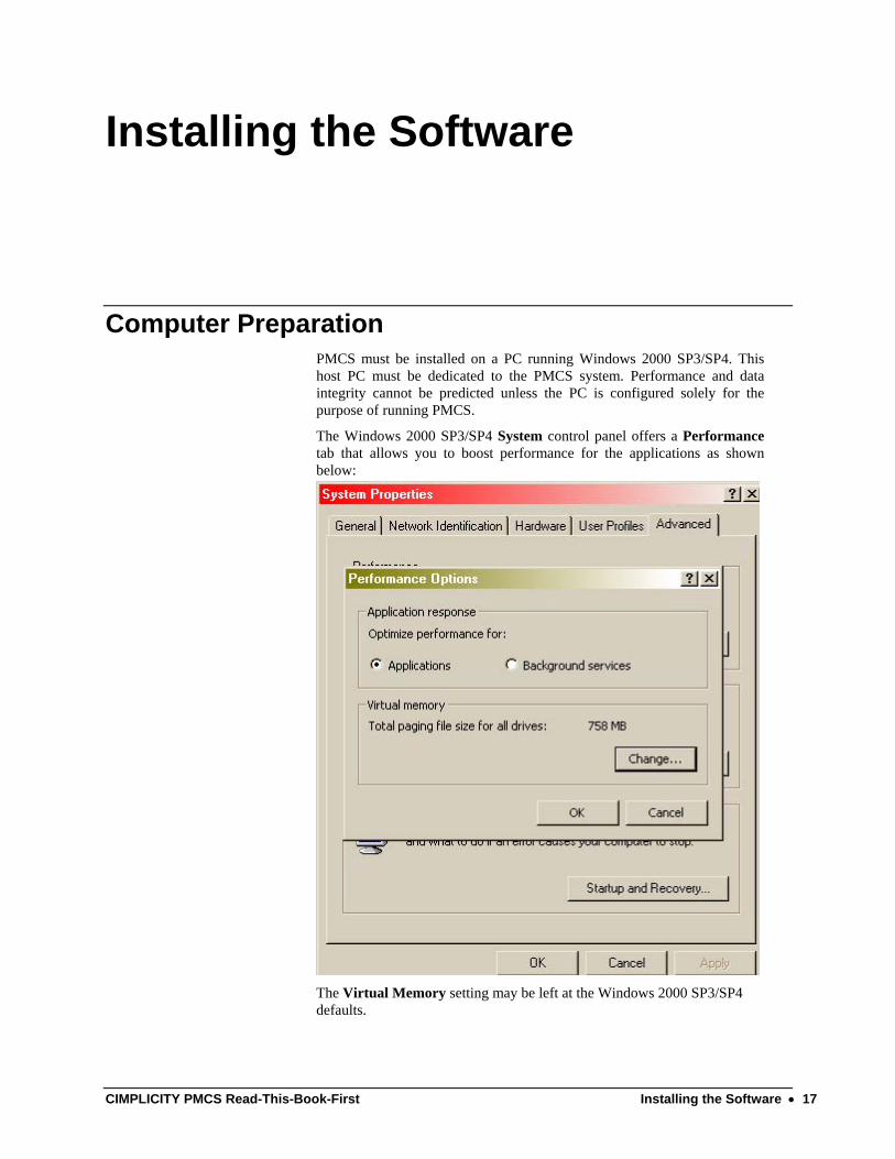
Computer Preparation PMCS must be installed on a PC running Windows 2000 SP3/SP4. This host PC must be dedicated to the PMCS system. Performance and data integrity cannot be predicted unless the PC is configured solely for the purpose of running PMCS.
The Windows 2000 SP3/SP4 System control panel offers a Performance tab that allows you to boost performance for the applications as shown below:
The Virtual Memory setting may be left at the Windows 2000 SP3/SP4 defaults.
CIMPLICITY PMCS Read-This-Book-First Installing the Software • 17
Make sure your system meets these requirements before proceeding with the remaining installation steps. PMCS will not run correctly unless these requirements are satisfied.
Installing CIMPLICITY If CIMPLICITY HMI was provided with your PMCS software, you must install it before proceeding. If your computer already has CIMPLICITY HMI installed, make sure the following requirements are met.
• CIMPLICITY HMI for Windows 2000 SP3/SP4 (Intel) Version 6.1 is required. Other versions of CIMPLICITY may not be compatible with PMCS.
If you are installing CIMPLICITY HMI, follow the directions provided with the software (inside the CD jewel case). Choose CIMPLICITY HMI as the product to install, then select either the HMI Server or Viewer as the product option to install, and C:\CIMPLICITY\HMI as the installation directory. If you install the Server option, also install Server Option - Communications - Advanced DDE/DDE Client.
Installing Additional Software Install any additional software, such as Microsoft Excel, at this point in the procedure. Follow the instruction procedures provided by the manufacturer.
RS485 PMCS Network Interfaces If you are using an RS485 interface card to connect to the PMCS network, install the card following the manufacturer’s installation instructions. Be sure to install any Windows NT drivers provided by the interface-card vendor. Typically, drivers are installed at Control Panel>Administrative Tools >Computer Management>System Information> Components>Network>Adapter by following the instructions. You may be prompted to insert the manufacturer’s disk into the A: drive.
18 • Installing the Software CIMPLICITY PMCS Read-This-Book-First
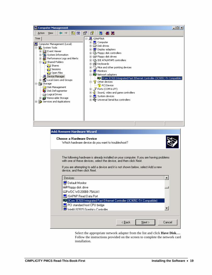
Select the appropriate network adapter from the list and click Have Disk…. Follow the instructions provided on the screen to complete the network card installation.
CIMPLICITY PMCS Read-This-Book-First Installing the Software • 19
For PMCS systems using one or more GE Multilin RS232 to RS485 converters (or equivalent), no additional drivers are required.
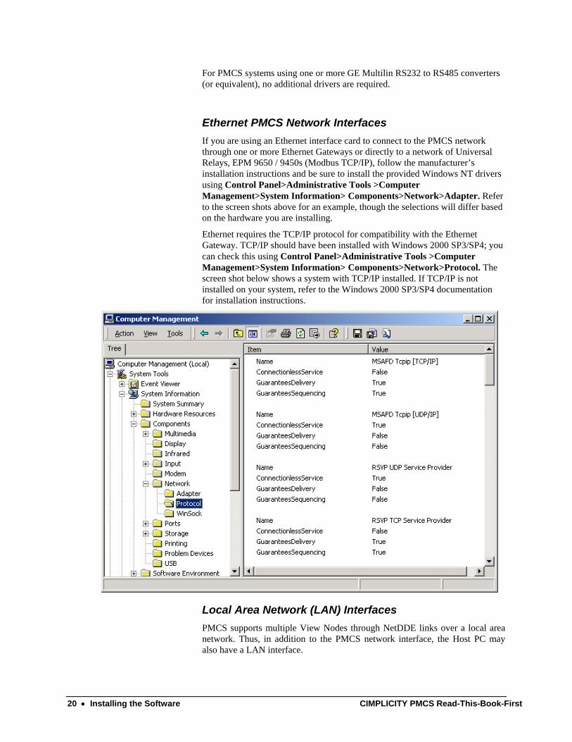
Ethernet PMCS Network Interfaces If you are using an Ethernet interface card to connect to the PMCS network through one or more Ethernet Gateways or directly to a network of Universal Relays, EPM 9650 / 9450s (Modbus TCP/IP), follow the manufacturer’s installation instructions and be sure to install the provided Windows NT drivers using Control Panel>Administrative Tools >Computer Management>System Information> Components>Network>Adapter. Refer to the screen shots above for an example, though the selections will differ based on the hardware you are installing.
Ethernet requires the TCP/IP protocol for compatibility with the Ethernet Gateway. TCP/IP should have been installed with Windows 2000 SP3/SP4; you can check this using Control Panel>Administrative Tools >Computer Management>System Information> Components>Network>Protocol. The screen shot below shows a system with TCP/IP installed. If TCP/IP is not installed on your system, refer to the Windows 2000 SP3/SP4 documentation for installation instructions.
Local Area Network (LAN) Interfaces PMCS supports multiple View Nodes through NetDDE links over a local area network. Thus, in addition to the PMCS network interface, the Host PC may also have a LAN interface.
20 • Installing the Software CIMPLICITY PMCS Read-This-Book-First

A Host PC with an Ethernet PMCS network interface may use either the same Ethernet card as the LAN interface or a separate LAN interface card. A Host PC with an RS485 PMCS network interface requires an additional LAN interface card to support View Nodes.
Typical LAN interface cards include Ethernet and Token Ring. Any LAN interface card should be installed according to the manufacturer’s instructions.
CIMPLICITY PMCS Read-This-Book-First Installing the Software • 21

Installing Additional Software Install any additional software, such as Microsoft Excel or COMTRADE file browsers for analyzing waveform files, at this point in the procedure. Follow the instruction procedures provided by the manufacturer.
Installing the EPM Software Components The EPM 7700, EPM 7600 and EPM 7500 Meters require additional software to operate with PMCS client software such as the Event Logger, Waveform Capture Module, or CIMPLICITY Wizards. This is because the EPM 7700, EPM 7600 and EPM 7500 are not compatible with the standard PMCS DDE Server. Instead, a separate DDE Server called the 7700 Gateway Server must be installed, along with a pair of ‘helper’ applications, the Communications Server and the ION_Link Server. The Communications Server processes all communications between the Gateway Server and/or the ION_Link and the Ethernet-based EPM 7700, EPM 7600 and EPM 7500 meters.
The EPM 7700 software may be selected during the standard PMCS installation routine. If you are not using any EPM devices in your PMCS setup, you do not need to install the EPM options during PMCS installation.
The EPM software components do require some special configuration beyond that required for other PMCS components. Refer to the section titled EPM Device Special Considerations for details after running the installation routine described in this section.
22 • Installing the Software CIMPLICITY PMCS Read-This-Book-First
Installing the PMCS software Once you have set up Windows NT and any third-party software (if appropriate) you are ready to install the PMCS software. PMCS should be installed last, after all other software installations are completed. Your PMCS software is provided on a CD-ROM.
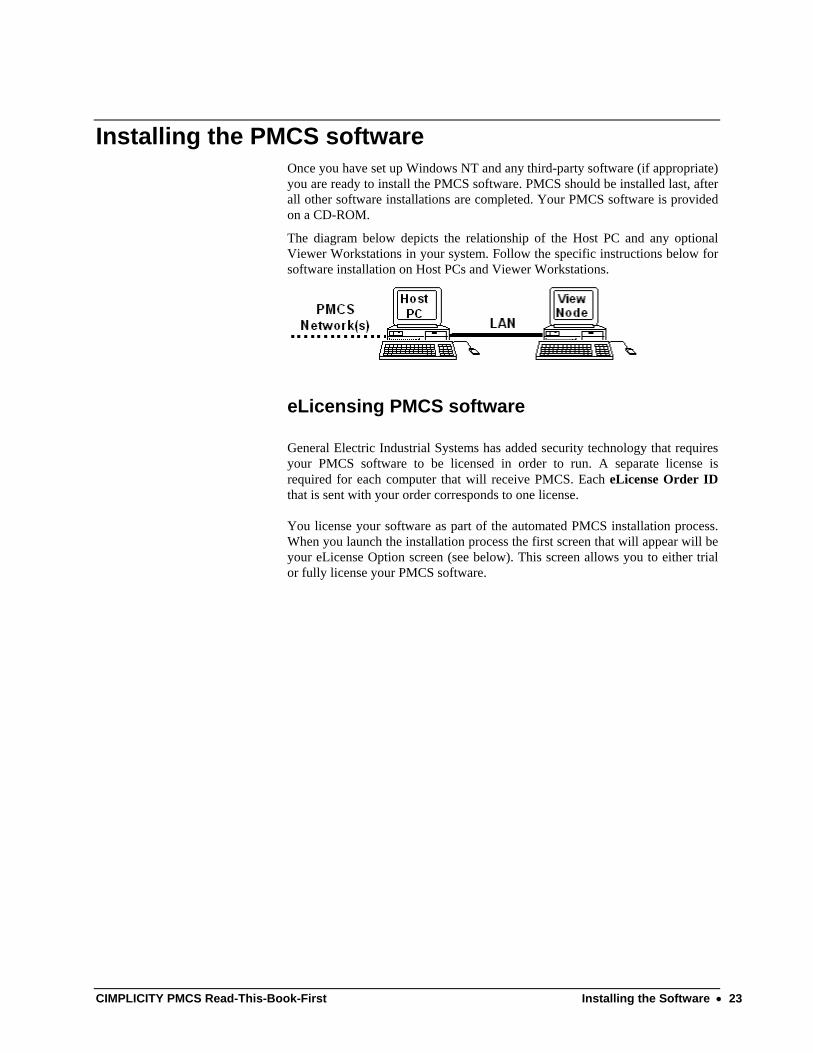
The diagram below depicts the relationship of the Host PC and any optional Viewer Workstations in your system. Follow the specific instructions below for software installation on Host PCs and Viewer Workstations.
eLicensing PMCS software General Electric Industrial Systems has added security technology that requires your PMCS software to be licensed in order to run. A separate license is required for each computer that will receive PMCS. Each eLicense Order ID that is sent with your order corresponds to one license. You license your software as part of the automated PMCS installation process. When you launch the installation process the first screen that will appear will be your eLicense Option screen (see below). This screen allows you to either trial or fully license your PMCS software.
CIMPLICITY PMCS Read-This-Book-First Installing the Software • 23

720 Hours (30-Day) Trial You have the option to Trial PMCS for 720 Hours (30 days) through the 720 Hours Trial selection on this screen. All functionality of PMCS is available to trial users and all configurations made for the software will be maintained from one use to the next. A single trial is registered to each PC and may not be uninstalled and re-installed for another trial.
Licensing via the Web Choose the Web License option if you have a working Internet connection on your PMCS computer. This option will automatically connect you to General Electric Industrial Systems’ eLicense distribution system. Once connected, an automated process will retrieve your unique PMCS eLicense key. Selecting the Web License option from the License Option brings you to the Web License Screen. This screen requires you to enter your eLicense Order ID. This information is contained on the Order Confirmation Sheet that accompanied your PMCS software or it can be obtained from your Purchase Confirmation e-mail Enter the Order ID and click on Get License to initiate the
24 • Installing the Software CIMPLICITY PMCS Read-This-Book-First

Web connection to General Electric Industrial Systems’ eLicense distribution system.
Similar to the trial, each eLicense is registered to the computer in which case, the eLicense Order ID can only be used for one computer The software must be unlicensed to be re-licensed with the same eLicense Order ID on another computer Select Launch from your License Installation Success Screen to continue installing PMCS.
Host PC Installation Every PMCS system requires one Host PC that is directly connected to the PMCS network and communicates with the power-management devices. The Host PC is also typically used to view and analyze data.
If you are installing multiple PMCS catalog numbers on the Host PC, you will need the CD and serial number from each package. Follow the Installation Steps section below. If the Host PC will be providing data to View Nodes, be sure to refer to GEH-6510, Network and Device Configurator, to configure NetDDE for operation with the View Node PCs.
Viewer Workstation Installation PMCS supports optional Viewer Workstations, which interact with the power-management network through NetDDE links to the Host PC. Viewer Workstations are not directly connected to the PMCS network but are connected via LAN to the Host PC. Viewer Workstations are not mandatory in a PMCS system because the data is available for display and analysis at the Host PC. When installing PMCS View Nodes, be sure to use only an appropriate catalog number for the installation. Do not install any other PMCS software on a PMCS Viewer Workstation.
NOTE: The EPM software differs from the standard PMCS usage of Viewer Workstations. Refer to the section titled EPM Device - Special Considerations for more details on EPM Workstations and View Nodes.
PMCS Installation Steps Note: When the system on which PMCS is being installed is not having any database server installed on it. The PMCs 6.14 installation will go ahead by installing MSDE 1.0 for PMCS databases. This is applicable for all licenses where database installation takes place.
Follow the procedure below to install each PMCS catalog number. Be sure the catalog numbers you are installing are appropriate for the destination PC (Host PC or View Node). Close any open applications before installation.
1. Insert the PMCS Installation CD into the CD-ROM drive.
CIMPLICITY PMCS Read-This-Book-First Installing the Software • 25
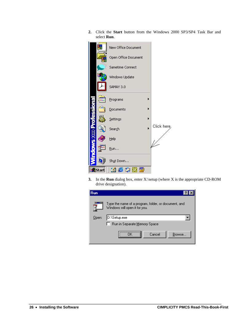
2. Click the Start button from the Windows 2000 SP3/SP4 Task Bar and select Run.
3. In the Run dialog box, enter X:\setup (where X is the appropriate CD-ROM
drive designation).
26 • Installing the Software CIMPLICITY PMCS Read-This-Book-First
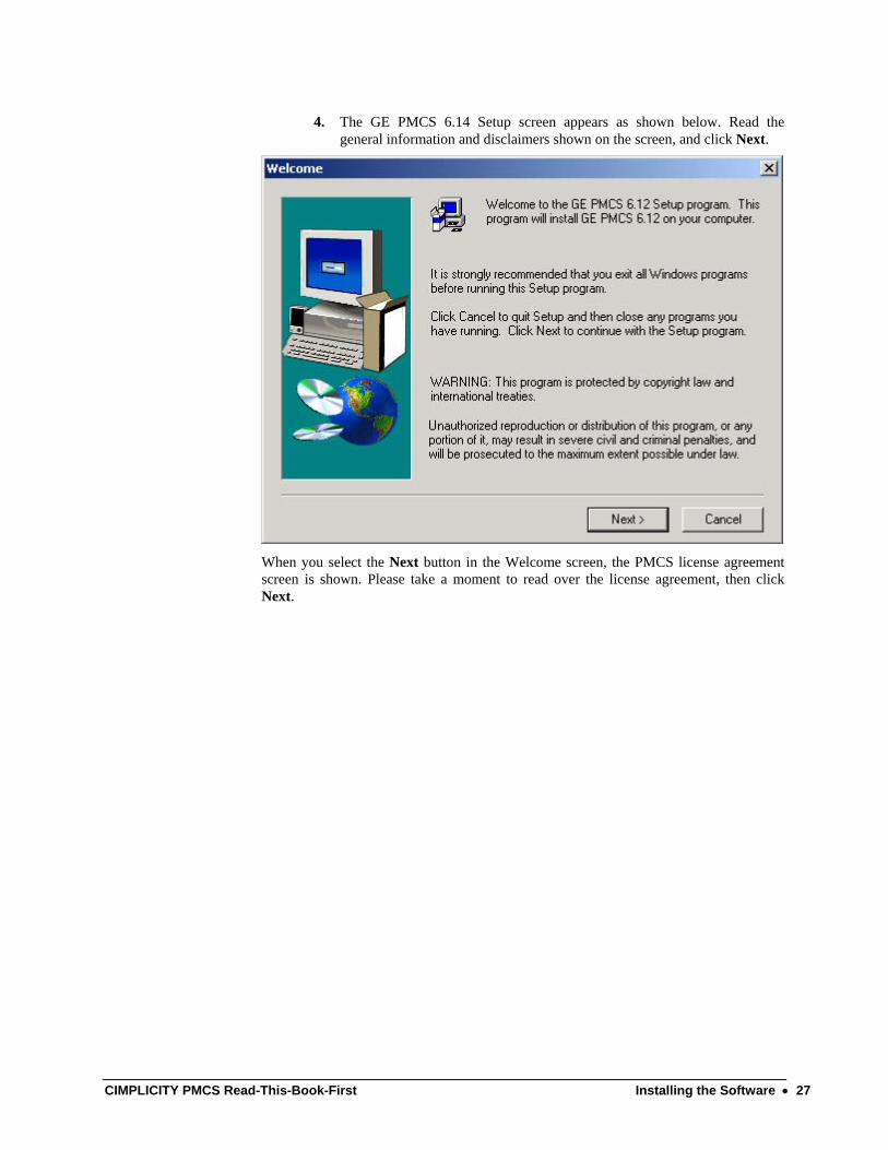
4. The GE PMCS 6.14 Setup screen appears as shown below. Read the general information and disclaimers shown on the screen, and click Next.
When you select the Next button in the Welcome screen, the PMCS license agreement screen is shown. Please take a moment to read over the license agreement, then click Next.
CIMPLICITY PMCS Read-This-Book-First Installing the Software • 27
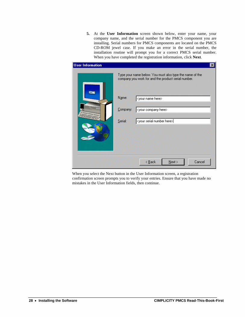
5. At the User Information screen shown below, enter your name, your company name, and the serial number for the PMCS component you are installing. Serial numbers for PMCS components are located on the PMCS CD-ROM jewel case. If you make an error in the serial number, the installation routine will prompt you for a correct PMCS serial number. When you have completed the registration information, click Next.
When you select the Next button in the User Information screen, a registration confirmation screen prompts you to verify your entries. Ensure that you have made no mistakes in the User Information fields, then continue.
28 • Installing the Software CIMPLICITY PMCS Read-This-Book-First
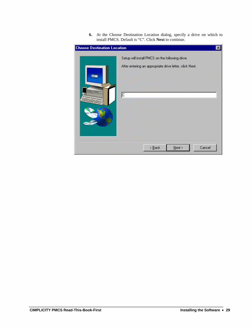
6. At the Choose Destination Location dialog, specify a drive on which to install PMCS. Default is “C”. Click Next to continue.
CIMPLICITY PMCS Read-This-Book-First Installing the Software • 29
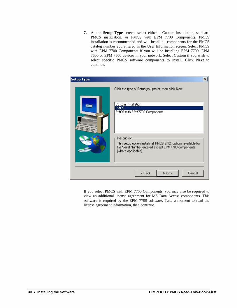
7. At the Setup Type screen, select either a Custom installation, standard PMCS installation, or PMCS with EPM 7700 Components. PMCS installation is recommended and will install all components for the PMCS catalog number you entered in the User Information screen. Select PMCS with EPM 7700 Components if you will be installing EPM 7700, EPM 7600 or EPM 7500 devices in your network. Select Custom if you wish to select specific PMCS software components to install. Click Next to continue.
If you select PMCS with EPM 7700 Components, you may also be required to view an additional license agreement for MS Data Access components. This software is required by the EPM 7700 software. Take a moment to read the license agreement information, then continue.
30 • Installing the Software CIMPLICITY PMCS Read-This-Book-First

8. If you did not select “PMCS with EPM 7700 Components” in the Setup Type dialog box (Step 7), skip this step and proceed to Step 11.
If you are installing the EPM 7700 Components, select whether this is to be a Primary node installation or Secondary node installation. You must install at least one Primary node on your PMCS network; it is recommended that you install the Primary node at the same machine as the PMCS DDE Server for convenience in configuration. Secondary nodes are akin to PMCS view nodes and may be installed on remote machines to access EPM 7700 data from the Primary node. (For additional details on Primary and Secondary nodes, see the section on configuring EPM 7700 components later in this chapter.)
CIMPLICITY PMCS Read-This-Book-First Installing the Software • 31
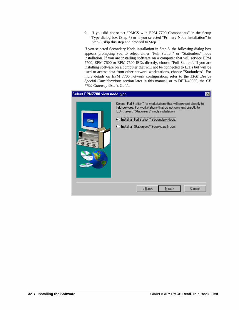
9. If you did not select “PMCS with EPM 7700 Components” in the Setup Type dialog box (Step 7) or if you selected “Primary Node Installation” in Step 8, skip this step and proceed to Step 11.
If you selected Secondary Node installation in Step 8, the following dialog box appears prompting you to select either "Full Station" or "Stationless" node installation. If you are installing software on a computer that will service EPM 7700, EPM 7600 or EPM 7500 IEDs directly, choose "Full Station". If you are installing software on a computer that will not be connected to IEDs but will be used to access data from other network workstations, choose "Stationless". For more details on EPM 7700 network configuration, refer to the EPM Device Special Considerations section later in this manual, or to DEH-40035, the GE 7700 Gateway User’s Guide.
32 • Installing the Software CIMPLICITY PMCS Read-This-Book-First
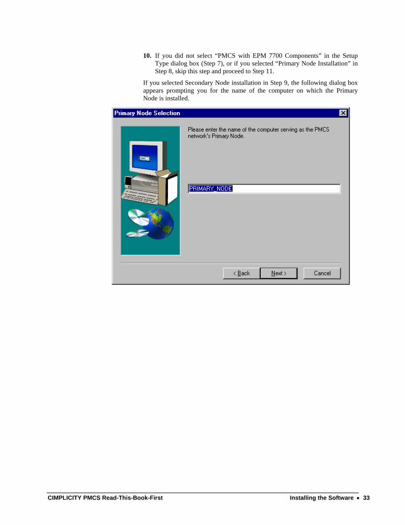
10. If you did not select “PMCS with EPM 7700 Components” in the Setup Type dialog box (Step 7), or if you selected “Primary Node Installation” in Step 8, skip this step and proceed to Step 11.
If you selected Secondary Node installation in Step 9, the following dialog box appears prompting you for the name of the computer on which the Primary Node is installed.
CIMPLICITY PMCS Read-This-Book-First Installing the Software • 33
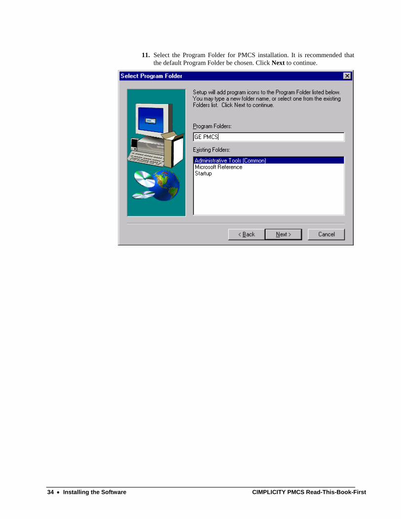
11. Select the Program Folder for PMCS installation. It is recommended that the default Program Folder be chosen. Click Next to continue.
34 • Installing the Software CIMPLICITY PMCS Read-This-Book-First
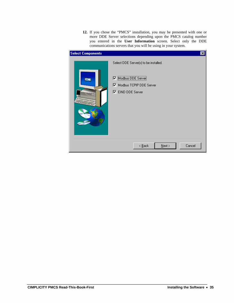
12. If you chose the “PMCS” installation, you may be presented with one or more DDE Server selections depending upon the PMCS catalog number you entered in the User Information screen. Select only the DDE communications servers that you will be using in your system.
CIMPLICITY PMCS Read-This-Book-First Installing the Software • 35
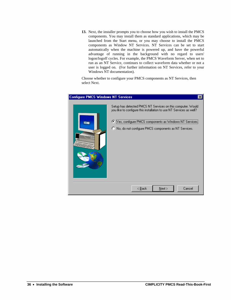
13. Next, the installer prompts you to choose how you wish to install the PMCS components. You may install them as standard applications, which may be launched from the Start menu, or you may choose to install the PMCS components as Window NT Services. NT Services can be set to start automatically when the machine is powered up, and have the powerful advantage of running in the background with no regard to users' logon/logoff cycles. For example, the PMCS Waveform Server, when set to run as an NT Service, continues to collect waveform data whether or not a user is logged on. (For further information on NT Services, refer to your Windows NT documentation).
Choose whether to configure your PMCS components as NT Services, then select Next.
36 • Installing the Software CIMPLICITY PMCS Read-This-Book-First
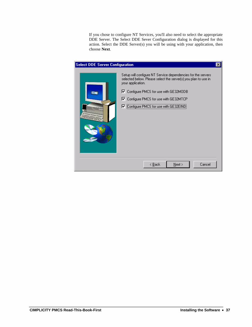
If you chose to configure NT Services, you'll also need to select the appropriate DDE Server. The Select DDE Sever Configuration dialog is displayed for this action. Select the DDE Server(s) you will be using with your application, then choose Next.
CIMPLICITY PMCS Read-This-Book-First Installing the Software • 37
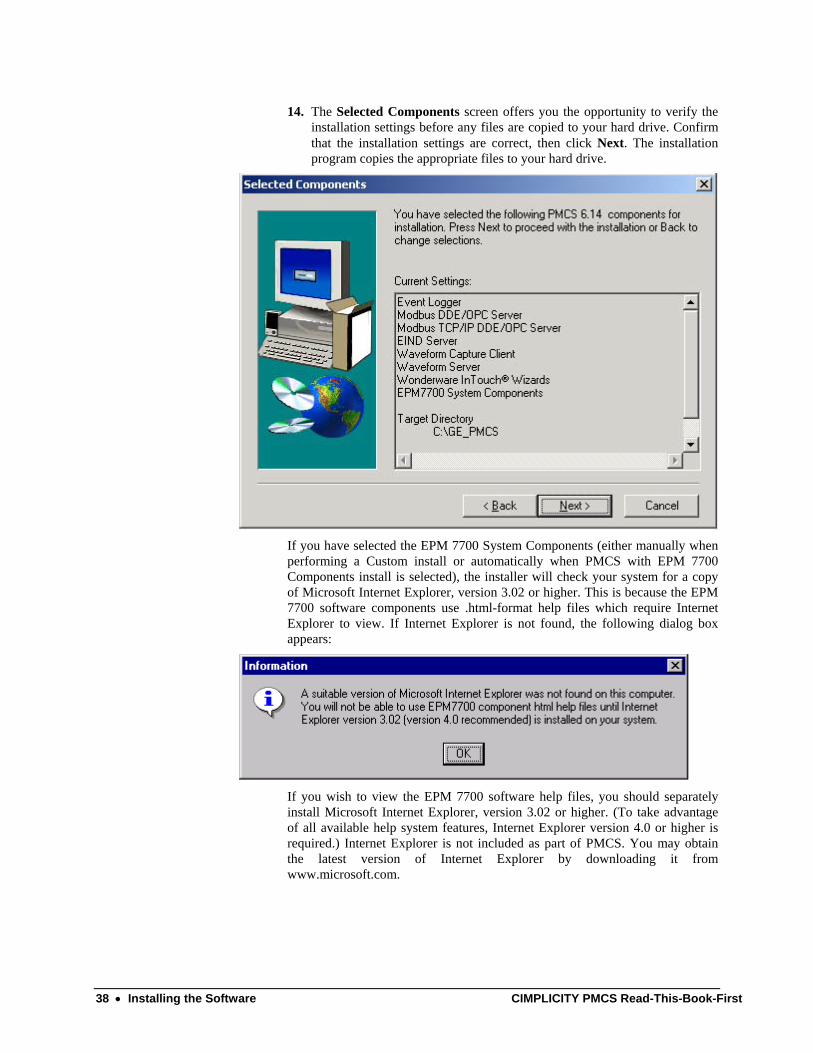
14. The Selected Components screen offers you the opportunity to verify the installation settings before any files are copied to your hard drive. Confirm that the installation settings are correct, then click Next. The installation program copies the appropriate files to your hard drive.
If you have selected the EPM 7700 System Components (either manually when performing a Custom install or automatically when PMCS with EPM 7700 Components install is selected), the installer will check your system for a copy of Microsoft Internet Explorer, version 3.02 or higher. This is because the EPM 7700 software components use .html-format help files which require Internet Explorer to view. If Internet Explorer is not found, the following dialog box appears:
If you wish to view the EPM 7700 software help files, you should separately install Microsoft Internet Explorer, version 3.02 or higher. (To take advantage of all available help system features, Internet Explorer version 4.0 or higher is required.) Internet Explorer is not included as part of PMCS. You may obtain the latest version of Internet Explorer by downloading it from www.microsoft.com.
38 • Installing the Software CIMPLICITY PMCS Read-This-Book-First
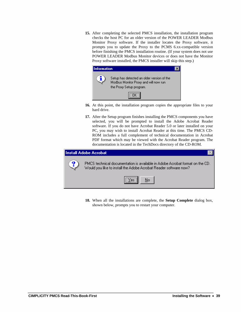
15. After completing the selected PMCS installation, the installation program checks the host PC for an older version of the POWER LEADER Modbus Monitor Proxy software. If the installer locates the Proxy software, it prompts you to update the Proxy to the PCMS 6.xx-compatible version before finishing the PMCS installation routine. (If your system does not use POWER LEADER Modbus Monitor devices or does not have the Monitor Proxy software installed, the PMCS installer will skip this step.)
16. At this point, the installation program copies the appropriate files to your
hard drive.
17. After the Setup program finishes installing the PMCS components you have selected, you will be prompted to install the Adobe Acrobat Reader software. If you do not have Acrobat Reader 5.0 or later installed on your PC, you may wish to install Acrobat Reader at this time. The PMCS CD-ROM includes a full complement of technical documentation in Acrobat PDF format which may be viewed with the Acrobat Reader program. The documentation is located in the TechDocs directory of the CD-ROM.
18. When all the installations are complete, the Setup Complete dialog box, shown below, prompts you to restart your computer.
CIMPLICITY PMCS Read-This-Book-First Installing the Software • 39
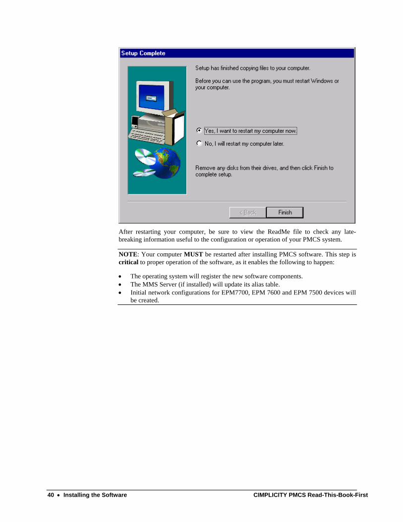
After restarting your computer, be sure to view the ReadMe file to check any late-breaking information useful to the configuration or operation of your PMCS system.
NOTE: Your computer MUST be restarted after installing PMCS software. This step is critical to proper operation of the software, as it enables the following to happen:
• The operating system will register the new software components. • The MMS Server (if installed) will update its alias table. • Initial network configurations for EPM7700, EPM 7600 and EPM 7500 devices will
be created.
40 • Installing the Software CIMPLICITY PMCS Read-This-Book-First
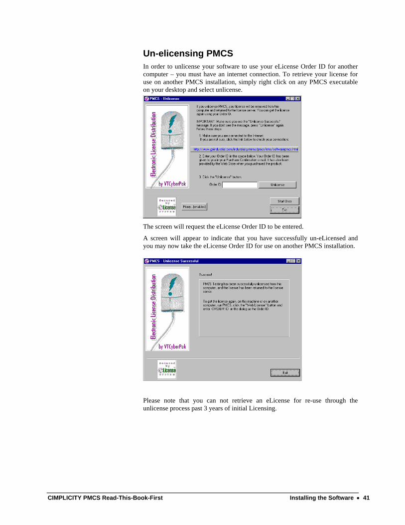
Un-elicensing PMCS In order to unlicense your software to use your eLicense Order ID for another computer – you must have an internet connection. To retrieve your license for use on another PMCS installation, simply right click on any PMCS executable on your desktop and select unlicense.
The screen will request the eLicense Order ID to be entered.
A screen will appear to indicate that you have successfully un-eLicensed and you may now take the eLicense Order ID for use on another PMCS installation.
Please note that you can not retrieve an eLicense for re-use through the unlicense process past 3 years of initial Licensing.
CIMPLICITY PMCS Read-This-Book-First Installing the Software • 41

Uninstalling PMCS All PMCS software is provided with an uninstall utility to fully remove PMCS components from your system. Uninstalling PMCS will permanently delete any configuration information.
NOTE: The Uninstaller may not delete some files such as error logs, system logs, and configuration records, which are created after the PMCS installation is complete. Since these files are not part of the initial installation, they will not be removed by the Uninstaller, and must be deleted manually.
If you are uninstalling EPM 7700 components, be aware that the Pegasys System Log Service does not properly unregister itself as an NT Service. The following procedure will allow you to manually uninstall this component: the remaining PMCS software can then be uninstalled in the usual manner.
Uninstalling the Pegasys System Log Service: 1. Open a Command Prompt window.
2. Make the C drive the current directory (assuming your Windows system files reside on the C drive).
3. Type “slservice –e” EXACTLY as shown and hit enter.
4. If the Pegasys System Log Service was installed and running you will receive the message “Pegasys System Log Service stopped”. If you do not receive this message, the Log Service was not installed on your system. Exit the command prompt and continue uninstalling PMCS.
5. If you received the correct message in step 4, uninstall the service. Type “slservice –u” EXACTLY as shown and hit enter. A message appears indicating “Pegasys System Log Service uninstalled”. Exit the command prompt and continue uninstalling PMCS.
42 • Installing the Software CIMPLICITY PMCS Read-This-Book-First

Reinstallation Steps Follow the procedure below to reinstall your PMCS software.
1. If your system includes the PMCS Interface Toolkit, uninstall the CIMPLICITY Wizards from any third-party HMI tools.
2. Close any open applications.
3. Insert the PMCS Version 6.14 CD into the CD-ROM drive.
4. From Start menu, select Run and enter X:\setup (where X is the appropriate CD-ROM drive designation).
5. Read the general information and disclaimers shown on the screen and click Next.
6. Enter your name, your company name, and the serial number located on the PMCS CD jewel case, then click Next. If you make an error in the serial number, the installation routine will prompt you for a correct PMCS serial number.
7. Choose the installation type; either PMCS, PMCS with EPM 7700 Components, or Custom installation. PMCS or PMCS with EPM 7700 Components installation will reinstall all components of the appropriate PMCS catalog number. Select Custom if you wish to reinstall only selected PMCS software components.
CIMPLICITY PMCS Read-This-Book-First Installing the Software • 43

Upgrading from previous versions to PMCS 6.14 PMCS 6.14 provides an easy-to-use, automatic upgrade path from previous versions of PMCS. The software installer examines your hard drive and, if it locates any previous version of PMCS, it makes decisions on upgrading each component.
Follow the procedure below to upgrade your currently installed PMCS version (such as 5.0, 5.1, or 6.xx) to PMCS version 6.14. This procedure assumes you have an existing PMCS installation with configured ports, topics and (optionally) generic topics, and that CIMPLICITY Wizards are installed in the generic HMI application.
WARNING: PMCS 5.1 and PMCS 5.1b Modbus DDE Server users only: Upgrading from PMCS 5.1 to PMCS 6.14 may cause the Modbus version of the DDE Server to lose its port configuration. You may need to reconfigure your communications ports from the PMCS DDE Server after upgrading. The Ethernet version of the DDE Server is not affected.
PMCS 5.0 users: Port configuration is lost when a PMCS 5.0 configuration file is converted to a PMCS 5.1b configuration file. You will need to reconfigure your communications ports from the PMCS DDE Server. Refer to GEH-6510 for instructions. Also, any generic topics you may have configured at the PMCS DDE Server will be lost, and you will need to re-configure these generic topics.
Note: While upgrading the previous versions to PMCS 6.14, a message appears saying that EPM 7330 device is configured as a generic device and in PMCS 6.14 this device is a tightly integrated device. Ignore this message and proceed further.
1. Close any open applications, and insert the PMCS 6.14 CD into the CD-ROM drive.
2. From Start menu, select Run and enter X:\setup (where X is the appropriate CD-ROM drive designation).
3. Read the general information and disclaimers shown, then click Next.
4. Enter your name, your company name, and the serial number located on the PMCS CD jewel case, then click Next. If you make an error in the serial number, the installation routine prompts you for a correct PMCS serial number.
5. Choose either PMCS, PMCS with EPM 7700 Components or Custom installation. PMCS or PMCS with EPM 7700 Components installation will reinstall all components of the appropriate PMCS catalog number. Select Custom if you wish to reinstall only selected PMCS software components.
6. After upgrading, existing HMI applications that use PMCS wizards will continue to work. If you upgrade device firmware you will need to replace the old wizard screens with new screens to maintain compatibility between your application and the device. The old PMCS wizards will remain on your system unless you uninstall the previous version of PMCS. It is highly recommended that all new applications use PMCS 6.14 Advanced wizards exclusively.
7. After upgrading, launch the PMCS DDE Server. The Server will convert your previous PMCS configuration to a PMCS 6.14 configuration.
44 • Installing the Software CIMPLICITY PMCS Read-This-Book-First

WARNING: Event Logger users only: Upgrading your EventServer or Eventlogger application will result in the loss of all device configurations and annunciator panel items. Make a list of these items so that they may be reconstructed in the new application. Existing database files will be backed up by the installation program, but they cannot be viewed with the PMCS 6.14 EventViewer. To view databases created with earlier editions of PMCS, use Microsoft Access to open the .mdb files.
CIMPLICITY PMCS Read-This-Book-First • 45

(This page left blank intentionally)
46 • CIMPLICITY PMCS Read-This-Book-First
Working with Cimplicity Viewer Node How to view the screens on a viewer node
To configure the project on a Cimplicity viewer node, running on a HMI server, follow the directions below.
1) Install Cimplicity HMI 6.1 SP1 on one machine with HMI Server option on a Windows 2000 SP3/SP4 machine.
2) Install PMCS 6.14 on the same machine with the serial numbers given.
3) Install Cimplicity HMI 6.1 on another machine with Viewer Runtime option on a Windows 2000 SP3/SP4 machine.
4) Install PMCS 6.14 on the same machine with the serial numbers given for a viewer node, which installs Runtime wizards and WC and EV only.
5) Now create a project in HMI Server node, with Enable project Broadcast option. Drop the wizards which contains LFP and also tab selection mode wizards.
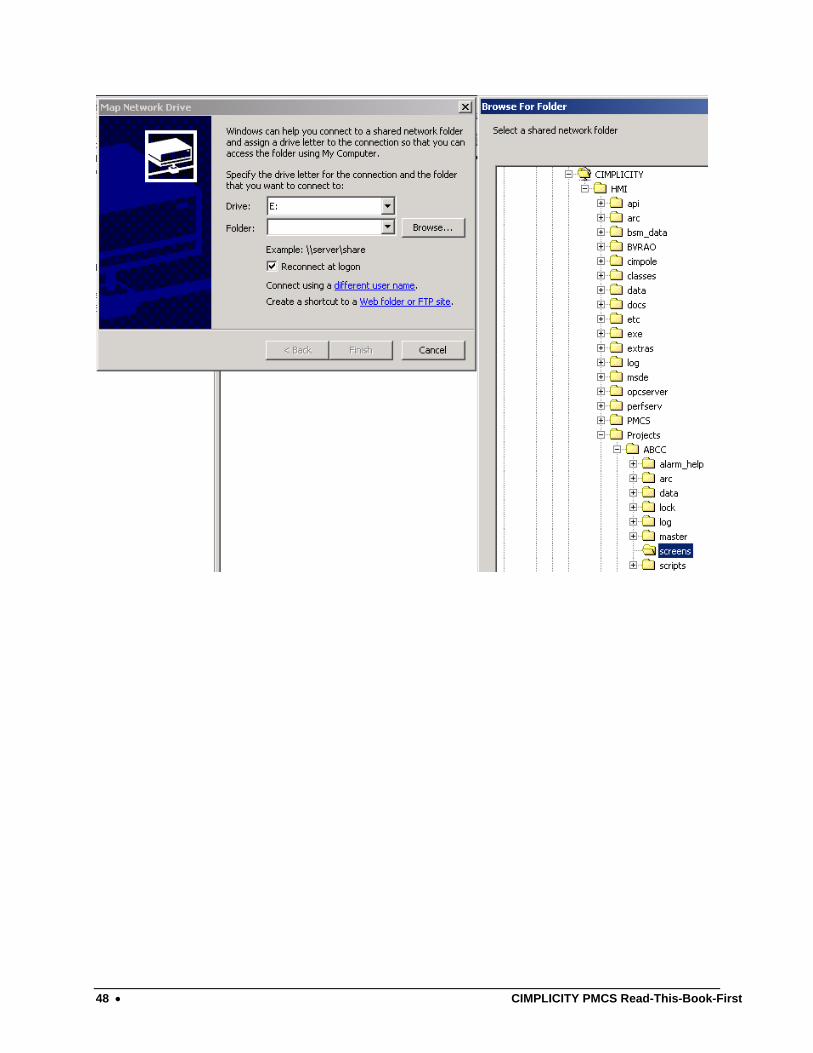
6) On the viewer node now map the drive (preferably Cimplicity Directory) of HMI server node.
7) Important Note: On the viewer node neither you copy the project nor screens.
8) Now after mapping the drive, open the MainMenu.cim file, which is on HMI server node from the Viewer node. Or On the viewer node, Go to Start\Programs\Cimplicity\HMI\Cimview-> Common dialog box appears, select\point the Mainmenu.cim file (obviously on the HMI server node’s file). See the following figure.
9) Open the small faceplate wizard files to get the configured screens.
CIMPLICITY PMCS Read-This-Book-First Working with Cimplicity Viewer Node • 47
48 • CIMPLICITY PMCS Read-This-Book-First

Configuring the Software
To get the most out of your new PMCS system, follow the directions below to configure your system.
Organize Your Information
Host PC You need the following information to properly configure the PMCS software for the Host PC. This information is used throughout the configuration process and you should archive it for any future maintenance of your system.
For RS485 PMCS network interfaces, you need to list all devices in the power-management network (including Modbus Concentrators) with associated device types, Modbus RTU addresses, and COM ports. Assign names of less than 20 characters (no spaces) to these devices.
For example, in a simple system with four devices (and one Modbus Concentrator), you may have a table similar to the following:
COM port Modbus RTU Address Device Type Device (Topic) Name 1 2 MODCONC MCI 1 12 E3720 Main_Meter 1 33 PLEPM Mfg_Meter 1 61 MVT Mfg_Breaker 2 210 ML269 Mill_Relay
For an Ethernet PMCS network interface (Ethernet Gateway), you must list all devices in the power-management network, including the device types and Modbus RTU addresses. You need to know the appropriate Ethernet Gateway IP address and COM port (1–4) to which each device is connected. Assign names of less than 20 characters (no spaces) to these devices.
For example, in a simple system with 10 devices, you may have a table similar to the following (this system uses one Ethernet Gateway and other devices).
CIMPLICITY PMCS Read-This-Book-First Configuring the Software • 49

Ethernet Gateway IP Address
COM port
Modbus RTU Address
Device Type
Device (Topic) Name
10.47.28.201 1 2 EPM 9650Q E9650Q 10.47.28.201 1 12 E3720 Main_Meter 10.47.28.201 1 33 PLEPM Mfg_Meter 10.47.28.201 1 61 PLEPM Plating_Meter 10.47.28.201 2 12 UR L90 UR 10.47.28.201 2 66 PLEPM Office1_Meter 10.47.28.201 2 80 PLM Office2_Meter 10.47.28.201 2 90 MDP Feeder1_Relay 10.47.28.201 2 100 MVT Mfg_Breaker 10.47.28.201 3 200 ML269 Mill_Relay 10.47.28.201 4 21 EPM5350P E5350P 10.47.28.201 4 201 MVT Plating_Breaker 10.47.28.201 4 210 MVT Office_Breaker
View Node You should configure View Nodes after you have configured and tested the Host PC to ensure all functions are operating. View Nodes require a copy of the network architecture list used above. Refer to GEH-6510, Network and Device Configurator, for complete configuration instructions.
50 • Configuring the Software CIMPLICITY PMCS Read-This-Book-First

Configuration Procedure Follow the procedure below to efficiently configure your system and minimize your time to startup.
Host PC Configuration 1. Configure the DDE Server. Your Host PC will likely have several versions
of the DDE Server installed (RS485-Modbus, TCP/IP Modbus, TCP/IP Encapsulated Modbus and Ethernet-TCP/IP). Configure only the server appropriate for your PMCS network interface (GE32MODB, GE32MTCP, GE32GTWY or GE32ENET). See GEH-6510, Network and Device Configurator, for complete details.
2. EPM 7700, EPM 7600 and EPM 7500 users only (all others proceed to step 3): Configure the Communications Server and GE 7700 Gateway Server. If you installed the EPM software options and you are going to use EPM 7700, EPM 7600 or EPM 7500 devices in your PMCS network, you will need to configure both the Communications Server and the GE 7700 Gateway Server. For Comm Server configuration instructions, refer to EPM Software Components Configuration later in this guide. For GE 7700 Gateway Server configuration instructions, refer to DEH-40035, the GE 7700 Gateway Server User’s Guide.
3. Configure the user interface. If your system was provided with a generic HMI software application, either load or create the custom HMI (using the Interface Toolkit wizards, if appropriate; see DEH-210, CIMPLICITY PMCS Interface Toolkit or refer to the HMI software’s documentation.
4. Configure the applications. As appropriate, configure the following application modules, referring to the instruction manuals provided.
• Event Logger, GEH-6512 • Waveform Capture, GEH-6511
5. Test the applications. Test the functioning of all applications to ensure proper Host PC operation. Do not proceed to step 5 until you are sure the Host PC operates as expected.
6. Set up NetDDE. If your system has one or more View Nodes, set up NetDDE shares and trusts in the Host PC, following the procedures in GEH-6510, Network & Device Configurator and the CIMPLICITY HMI documentation.
7. Set up NetDDE. If your system uses the PMCS Waveform Capture client, and you intend to access waveform data from View Nodes, set up NetDDE shares and trusts for the PMCS Waveform Server following the procedures in GEH-6511, PMCS Waveform Capture Module.
Viewer Workstation Configuration 1. Configure the user interface. Load the custom HMI. Refer to the
CIMPLICITY HMI documentation as appropriate.
2. Configure the applications. As appropriate, configure the application modules, referring to the instruction manuals provided. See step 3 of the Host PC Configuration for the appropriate instruction manual numbers.
CIMPLICITY PMCS Read-This-Book-First Configuring the Software • 51

EPM Software Components Configuration The EPM 7700, EPM 7600 and EPM 7500 requires several separate software components which are installed during the PMCS setup. This section provides a brief overview of the steps required to configure these components; the following section describes the EPM software components in greater detail.
For details of using the NetBuilder software, refer to the Configuring the EPM 7700 Device Network section of this manual, and to DEH-440035, the GE 7700 Gateway User’s Guide.
1. Launch the NetBuilder application. From the Start menu, select Programs>Power Management Ltd>Utilities>Network Builder.
2. Insert a workstation(s). Normally all the workstations in a PMCS network are automatically configured during the installation of the software – these instructions are provided in case you need to enter the information manually. Select the Items menu from NetBuilder, and choose Workstation to insert a workstation. Name the workstation (up to 15 alphanumeric characters, the first character must be alphabetic), and choose OK. Repeat this step for each workstation (computer) in your network.
3. Insert Ethernet Sites. Select Items>Insert>Ethernet Site to insert an Ethernet site. Set the proper time synchronization options, then choose OK. Repeat this step to add additional sites to the workstation if necessary.
4. Insert devices to the site. Select Items>Insert>Device, and complete the dialog box with the proper device type, Group, Ethernet address and name for an Ethernet device (EPM 7700, EPM 7600 or EPM 7500). The device name may be no more than eight alphanumeric characters, and the first character must be alphabetic. The IP service port field must be "7700" for any device connected to the Ethernet, and "7800" for any additional device connected through an EPM 7700’s RS485 port. Choose OK to close the Insert Device dialog box. Repeat this step as necessary to add additional devices to the site.
5. Save and exit. When all workstations, sites, and devices have been added, select the save icon and then exit.
52 • Configuring the Software CIMPLICITY PMCS Read-This-Book-First

(This page left blank intentionally)
CIMPLICITY PMCS Read-This-Book-First Configuring the Software • 53


EPM Device-Special Considerations
Introduction The GE EPM 7700, EPM 7600 and EPM 7500 devices add new level of power management capabilities to PMCS. These EPM devices also require some special configuration which is not necessary for other PMCS-compatible devices. This section describes the additional requirements and configuration steps necessary to use the EPM 7700, EPM 7600 and EPM 7500 in conjunction with PMCS.
NOTE: If you are not using the EPM 7700, EPM 7600 or EPM 7500 meters in your PMCS network, it is not necessary to read this section of the manual.
Although the EPM 7700, EPM 7600 and EPM 7500 meters are compatible with PMCS and its client applications (Waveform Capture, custom wizards, etc.), and EPM 7700, EPM 7600 and EPM 7500 meters may co-exist on the same Ethernet as other PMCS network segments, the EPM 7700, EPM 7600 and EPM 7500 use a slightly different metaphor than a straight PMCS network. An EPM device power-monitoring network is comprised of a number of nodes that are connected to the PMCS workstation through Ethernet links. Nodes in the power-monitoring network are IEDs such as the EPM 7700 meter (power meters are also referred to ‘meters’ or ‘devices’). IEDs may be distributed across one or more networks as required to service the particular application.
CIMPLICITY PMCS Read-This-Book-First EPM Device-Special Considerations • 55
EPM Software Components There are four major components of the EPM software. The Network Builder, ION Designer, Communications Server, and ION_LINK DDE Server each interact to support the EPM 7700, EPM 7600 and EPM 7500 Meters. When you selected the “PMCS with EPM 7700 Components” selection during the PMCS installation routine, these software components were installed automatically. The four components and their functions are described below.
Network Builder: Building the Network Configuration File The Network Builder presents a graphical view of the EPM 7700, EPM 7600 and EPM 7500 devices in your network, allowing you to easily add, remove or configure sites, services and meters. Network Builder creates a central network configuration file that holds information for the workstation, the network connections, and every connected device. You may want to restrict access to Network Builder or the network configuration file, since if the file is tampered with, EPM 7700, EPM 7600 and EPM 7500 components may be rendered inoperable.
ION Designer: Programming Devices and Software Nodes The ION Designer component allows you to customize the operation of an ION-compliant node, such as 7000-series meters and 3000-series meters. Be aware that misuse of ION Designer can adversely affect the operation of your meters.
IMPORTANT: For purposes of PMCS network compatibility, it is CRITICAL that any EPM 7700, EPM 7600 and EPM 7500 meters be configured with the GE PMCS standard configuration. Using ION Designer to customize EPM 7700, EPM 7600 or EPM 7500 functionality can compromise compatibility with the PMCS client applications attempting to access the device.
Communications Server: System Communications The Communications Server is the core communications component for EPM 7700, EPM 7600 and EPM 7500 meters. The Communications Server manages all communications between the meters connected to your network and the GE77GTWY and ION_Link DDE Server software applications.
ION_LINK DDE Server: Communication with Windows Applications The ION_LINK DDE Server uses Dynamic Data Exchange to share information with applications such as Microsoft Excel or the CIMPLICITY Wizards.
56 • EPM Device-Special Considerations CIMPLICITY PMCS Read-This-Book-First

Workstation Configuration Guidelines If you are using the EPM 7700, EPM 7600 or EPM 7500 Meters in your PMCS network, the following guidelines in this section must be adhered to before continuing with the EPM configuration.
NOTE: If you are adding a PMCS installation to an existing network, please refer your network administrator to GEH-6502, the PMCS Network Architecture Guide, for integration details.
• Each computer in the network must be assigned a Windows 2000 SP3/SP4 computer name. The name must be one to fifteen alphanumeric characters in length. Spaces may not be used, and the first character of the computer name may not be numeric.
• The System Control Panel should have the Performance Boost for Foreground Application value set to None, and a paging file should be created on the C: drive with the Initial and Maximum sizes set to twice the workstation’s installed RAM.
• The Network Control Panel’s Adapter tab should have the MS Loopback adapter installed if a physical network adapter is not installed in the workstation. Under the Protocols tab, TCP/IP or NetBEUI should be installed; if TCP/IP is installed, use IP address 192.168.100.xxx and subnet mask 255.255.255.0 unless your network administrator has assigned you an IP address. Under the Services tab, install Remote Access Server (RAS) and configure it by enabling NetBEUI (if using NetBEUI or, if TCP/IP is used, assign two or more IP addresses, starting at xxx.xxx.xxx.254 and working down. Set RAS to start automatically and set access to “entire network” (if available).
CIMPLICITY PMCS Read-This-Book-First EPM Device-Special Considerations • 57
Configuring the EPM Device Network
The PMCS installation routine described earlier in this manual creates initial workstation and software node entries in the EPM 7700 network configuration file. After EPM 7700 software components are installed, the next step is to add Ethernet sites and devices to the PMCS power-monitoring network using Network Builder software.
Running Network Builder Network Builder software presents your EPM power-monitoring network graphically, showing the installed components in a hierarchical tree. Network Builder allows you to edit the Network Configuration file— the file that identifies every node in the EPM power-monitoring network.
The first step is to run Network Builder from the Start Menu: (Programs > Power Measurement Ltd > Utilities > Network Builder.)
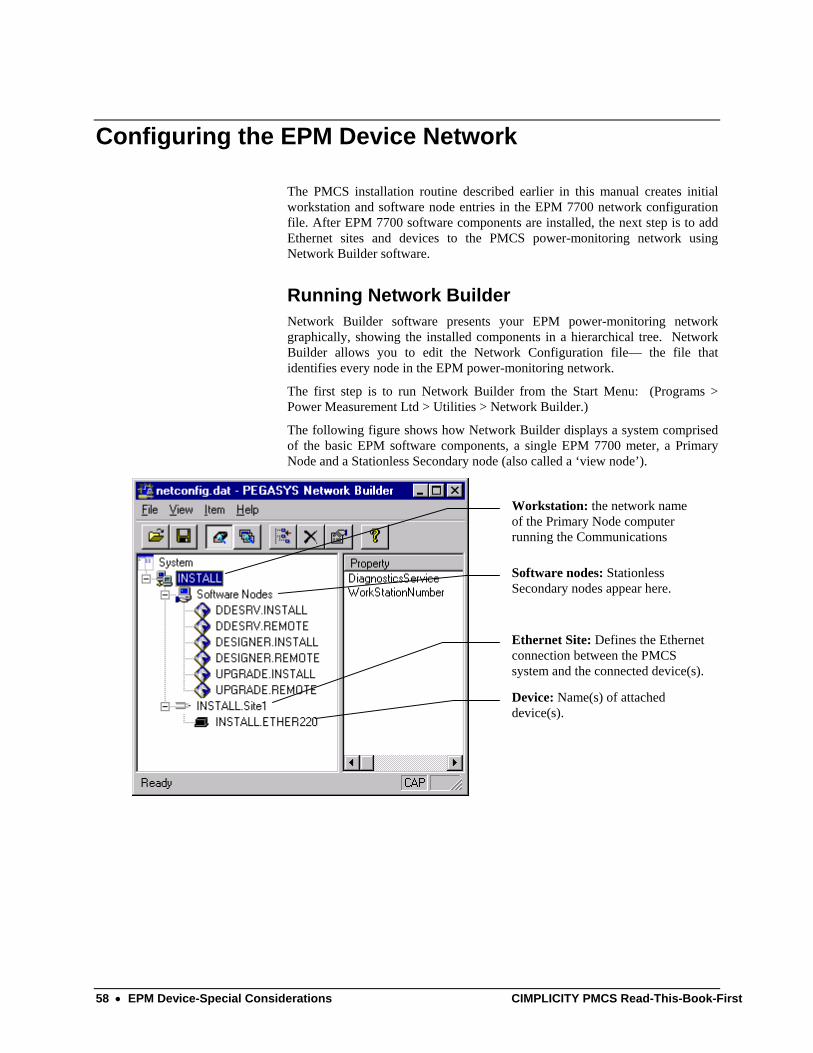
The following figure shows how Network Builder displays a system comprised of the basic EPM software components, a single EPM 7700 meter, a Primary Node and a Stationless Secondary node (also called a ‘view node’).
Workstation: the network name of the Primary Node computer running the Communications
Software nodes: Stationless Secondary nodes appear here.
Ethernet Site: Defines the Ethernet connection between the PMCS system and the connected device(s).
Device: Name(s) of attached device(s).
58 • EPM Device-Special Considerations CIMPLICITY PMCS Read-This-Book-First
Building the Power-Monitoring Network in NetBuilder When Network Builder is running, you can begin configuring your EPM system by adding a site to the workstation, then adding devices to the site. For larger systems multiple sites are added; one for each network of devices monitored.
NOTE: The PMCS installation wizard creates initial entries for the workstation and software nodes. If you do not need to make changes to the information provided during installation, skip this section and begin with the section title "Adding an Ethernet Site".
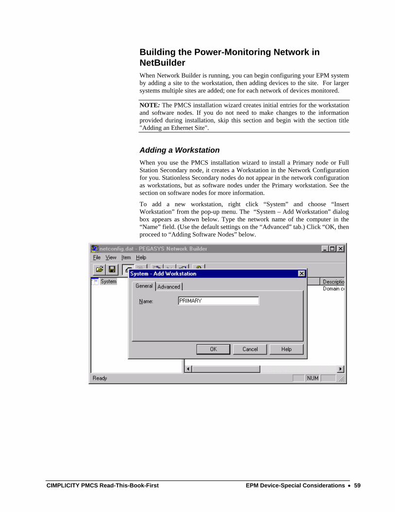
Adding a Workstation When you use the PMCS installation wizard to install a Primary node or Full Station Secondary node, it creates a Workstation in the Network Configuration for you. Stationless Secondary nodes do not appear in the network configuration as workstations, but as software nodes under the Primary workstation. See the section on software nodes for more information.
To add a new workstation, right click “System” and choose “Insert Workstation” from the pop-up menu. The “System – Add Workstation” dialog box appears as shown below. Type the network name of the computer in the “Name” field. (Use the default settings on the “Advanced” tab.) Click “OK, then proceed to “Adding Software Nodes” below.
CIMPLICITY PMCS Read-This-Book-First EPM Device-Special Considerations • 59
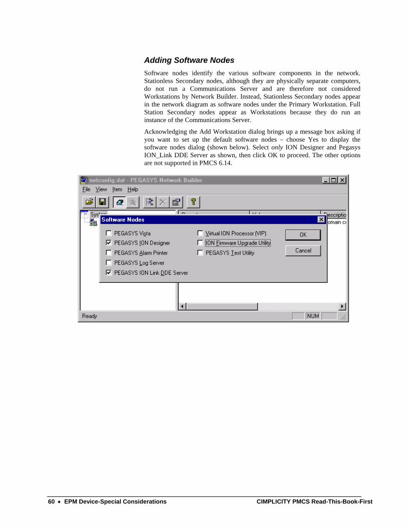
Adding Software Nodes Software nodes identify the various software components in the network. Stationless Secondary nodes, although they are physically separate computers, do not run a Communications Server and are therefore not considered Workstations by Network Builder. Instead, Stationless Secondary nodes appear in the network diagram as software nodes under the Primary Workstation. Full Station Secondary nodes appear as Workstations because they do run an instance of the Communications Server.
Acknowledging the Add Workstation dialog brings up a message box asking if you want to set up the default software nodes – choose Yes to display the software nodes dialog (shown below). Select only ION Designer and Pegasys ION_Link DDE Server as shown, then click OK to proceed. The other options are not supported in PMCS 6.14.
60 • EPM Device-Special Considerations CIMPLICITY PMCS Read-This-Book-First
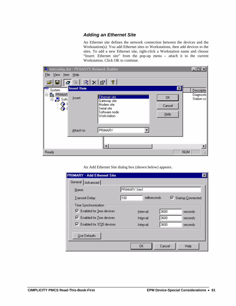
Adding an Ethernet Site An Ethernet site defines the network connection between the devices and the Workstation(s). You add Ethernet sites to Workstations, then add devices to the sites. To add a new Ethernet site, right-click a Workstation name and choose “Insert: Ethernet site” from the pop-up menu – attach it to the current Workstation. Click OK to continue.
An Add Ethernet Site dialog box (shown below) appears.
CIMPLICITY PMCS Read-This-Book-First EPM Device-Special Considerations • 61
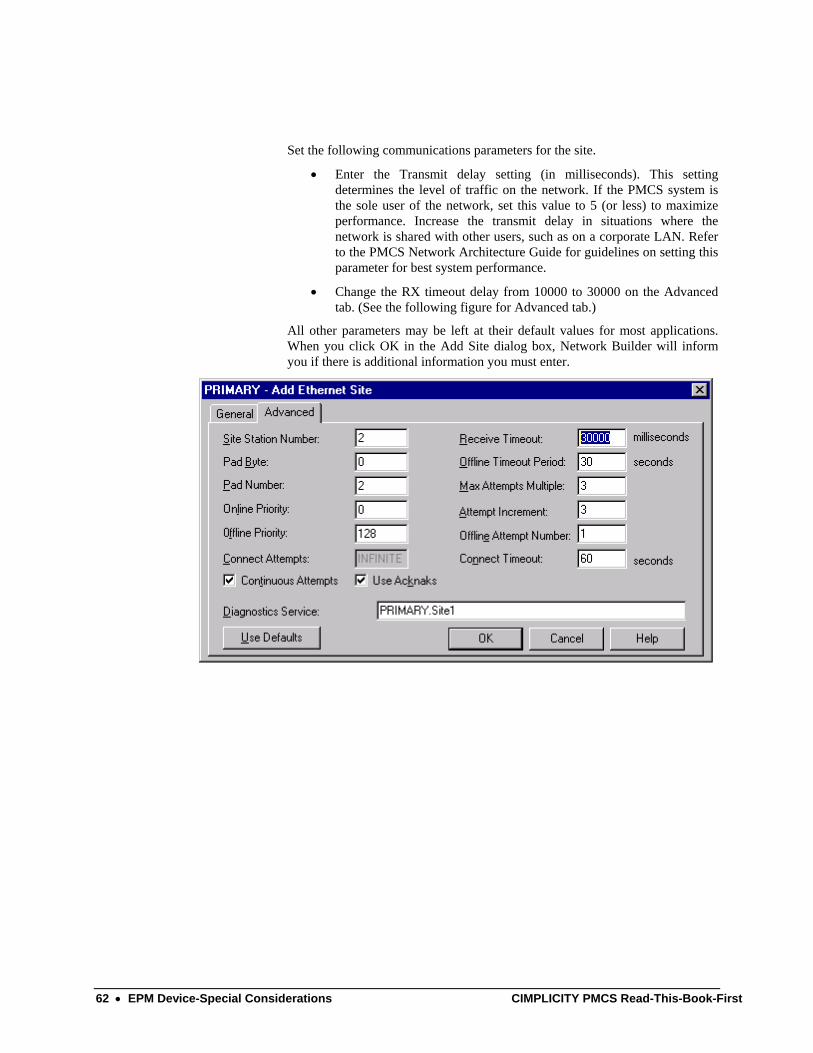
Set the following communications parameters for the site.
• Enter the Transmit delay setting (in milliseconds). This setting determines the level of traffic on the network. If the PMCS system is the sole user of the network, set this value to 5 (or less) to maximize performance. Increase the transmit delay in situations where the network is shared with other users, such as on a corporate LAN. Refer to the PMCS Network Architecture Guide for guidelines on setting this parameter for best system performance.
• Change the RX timeout delay from 10000 to 30000 on the Advanced tab. (See the following figure for Advanced tab.)
All other parameters may be left at their default values for most applications. When you click OK in the Add Site dialog box, Network Builder will inform you if there is additional information you must enter.
62 • EPM Device-Special Considerations CIMPLICITY PMCS Read-This-Book-First
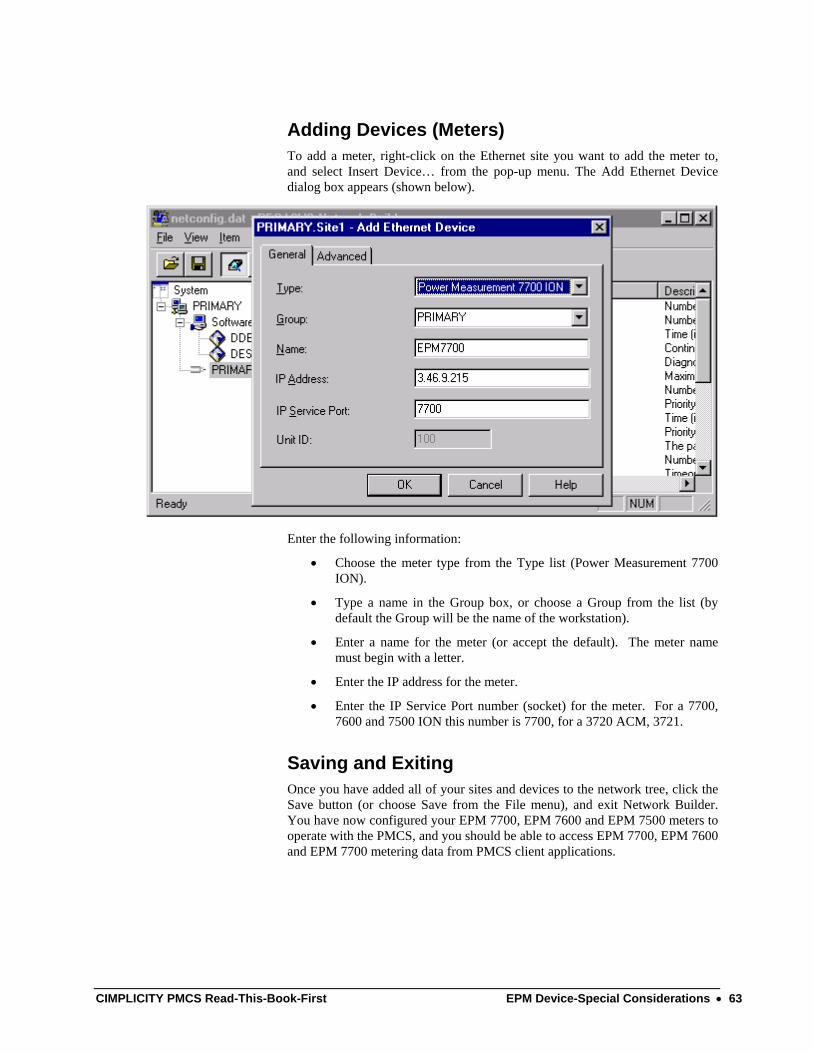
Adding Devices (Meters) To add a meter, right-click on the Ethernet site you want to add the meter to, and select Insert Device… from the pop-up menu. The Add Ethernet Device dialog box appears (shown below).
Enter the following information:
• Choose the meter type from the Type list (Power Measurement 7700 ION).
• Type a name in the Group box, or choose a Group from the list (by default the Group will be the name of the workstation).
• Enter a name for the meter (or accept the default). The meter name must begin with a letter.
• Enter the IP address for the meter.
• Enter the IP Service Port number (socket) for the meter. For a 7700, 7600 and 7500 ION this number is 7700, for a 3720 ACM, 3721.
Saving and Exiting Once you have added all of your sites and devices to the network tree, click the Save button (or choose Save from the File menu), and exit Network Builder. You have now configured your EPM 7700, EPM 7600 and EPM 7500 meters to operate with the PMCS, and you should be able to access EPM 7700, EPM 7600 and EPM 7700 metering data from PMCS client applications.
CIMPLICITY PMCS Read-This-Book-First EPM Device-Special Considerations • 63

(This page left blank intentionally)
64 • EPM Device-Special Considerations CIMPLICITY PMCS Read-This-Book-First

This page is intentionally left blank
CIMPLICITY PMCS Read-This-Book-First EPM Device-Special Considerations • 65

Index
A alarm, 4
D DDE Server, 58
E Ethernet, 4, 10, 18, 19, 51, 53 event, 4
F Fanuc, 4 First Steps, 9
I Interface Toolkit, 5, 10, 45, 53
M minimum system requirements, 3 Modbus Monitor Proxy, 37 Modbus RTU, 4, 10, 51
N NetBuilder, 54 Network Builder, 54
O option modules, 4
P PEGASYS
nodes, 57 Performance, 4
S servers
DDE, 58
T TCP/IP, 4, 10, 11, 18, 53 Technical Support, 3, 9, 14 Terminology, 9
W waveform capture, 4 Windows NT, 11, 18, 21
66 • Index CIMPLICITY PMCS Read-This-Book-First


GE MULTILIN General Electric Company 215 Anderson Avenue, Markham ON, L6E 1B3, CANADA USA & Canada: 1-800-547-8629 Global: (905) 294-6222 Fax: (905) 201-2098 Email: [email protected] <mailto:[email protected]>
DEH-211 R12 03/02 © 2000 – 2005 General Electric Company


