Download - Polled Serial Communications
1
Polled Serial CommunicationsPolled Serial Communications
These lecture notes created by Dr. Alex Dean, NCSU
2
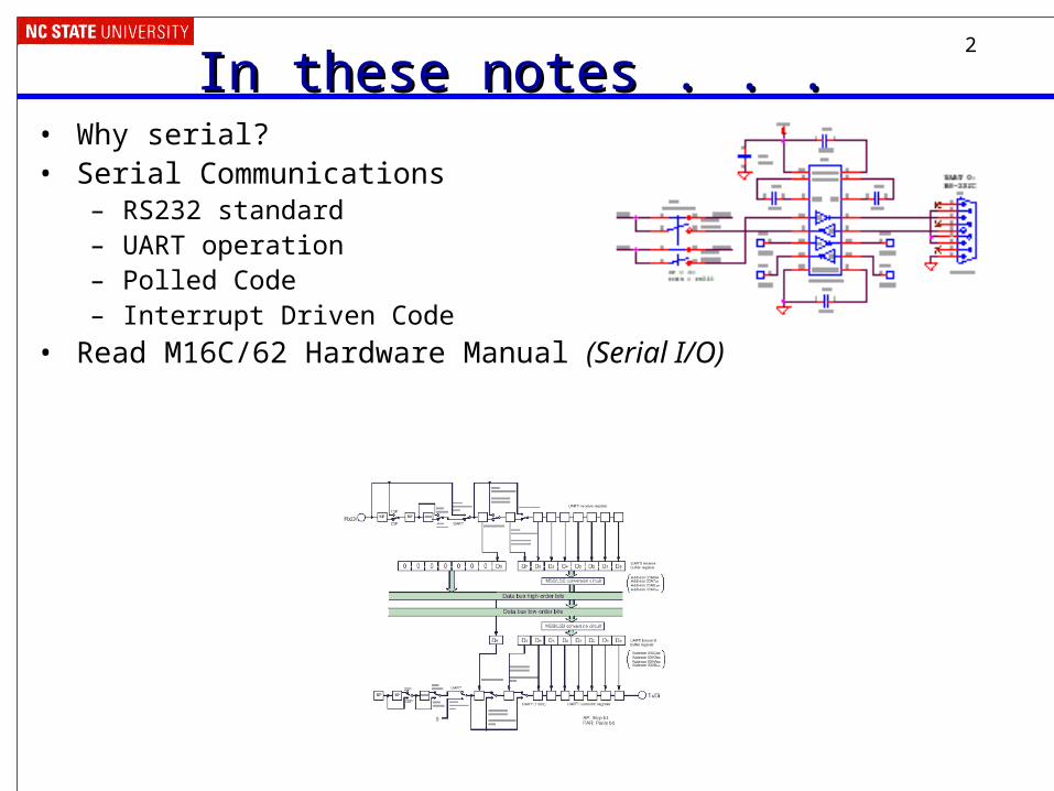
In these notes . . . In these notes . . . • Why serial?• Serial Communications
– RS232 standard– UART operation– Polled Code– Interrupt Driven Code
• Read M16C/62 Hardware Manual (Serial I/O)

3
Why Communicate Serially?Why Communicate Serially?• Native word size is multi-bit (8, 16, 32, etc.)• Often it’s not feasible to support sending all the word’s
bits at the same time– Cost and weight: more wires needed, larger connectors needed
– Mechanical reliability: more wires => more connector contacts to fail
– Timing Complexity: some bits may arrive later than others due to variations in capacitance and resistance across conductors
– Circuit complexity and power: may not want to have 16 different radio transmitters + receivers in the system
4
Example System: Voyager SpacecraftExample System: Voyager Spacecraft
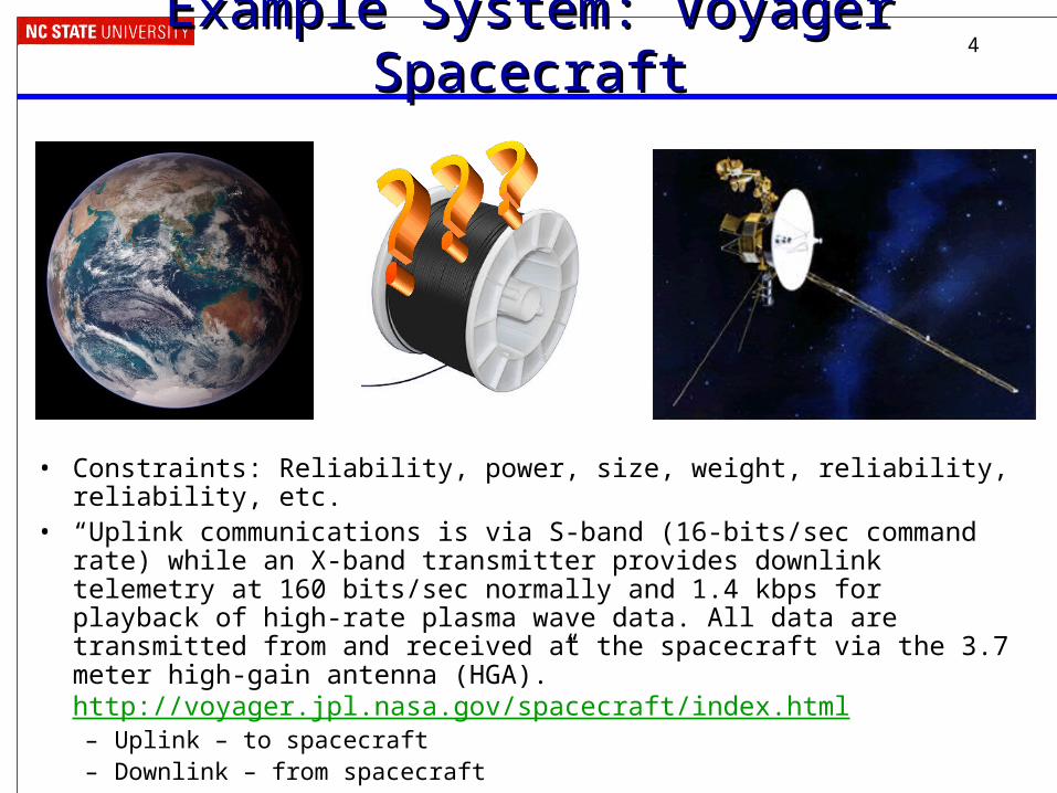
• Constraints: Reliability, power, size, weight, reliability, reliability, etc. • “Uplink communications is via S-band (16-bits/sec command rate) while an X-
band transmitter provides downlink telemetry at 160 bits/sec normally and 1.4 kbps for playback of high-rate plasma wave data. All data are transmitted from and received at the spacecraft via the 3.7 meter high-gain antenna (HGA).” http://voyager.jpl.nasa.gov/spacecraft/index.html – Uplink – to spacecraft– Downlink – from spacecraft

5
How can we communicate serially?How can we communicate serially?• Need clocking information
– When does a word start?– When is a bit being sent?– When does a word end?
• Options– Explicit clock – synchronous
• Separate signal– SPI has 1 clock and 1 data line
• Modify signal to provide clocking– Example: short pulse = 0, long pulse = 1
– Implicit clock – asynchronous• Transmitter and receiver follow same rules (protocol)• Protocol specifies how to know when word starts, when to sample bits,
when word is done– Maybe also error detection and other information
6
Asynchronous Serial Communication BasicsAsynchronous Serial Communication Basics
• Transmitter– If no data to send, keep sending 1 (stop bit)– When there is a data word to send
• Send a 0 (start bit) to indicate the start of a word• Send each data bit in the word (use a shift register for the transmit buffer)• Send a 1 (stop bit) to indicate the end of the word (keep sending it until more data
to send)• Receiver
– Wait for a falling edge (beginning of a Start bit)• Then wait ½ bit time • Do the following for as many data bits in the word
– Wait 1 bit time– Read the data bit and shift it into a receive buffer (shift register)
• Wait 1 bit time• Read the bit
– if 1 (Stop bit), then OK– if 0, there’s a problem!

7
For this to work…For this to work…• Transmitter and receiver must agree on several things
(protocol)– Order of data bits
– Number of data bits
– What a start bit is (1 or 0)
– What a stop bit is (1 or 0)
– How long a bit lasts• Transmitter and receiver clocks must be pretty close, since the only
timing reference is the start of the start bit
8
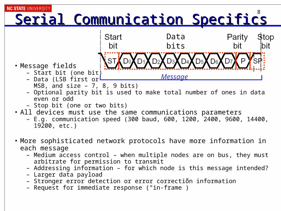
Serial Communication SpecificsSerial Communication Specifics
• Message fields– Start bit (one bit)– Data (LSB first or
MSB, and size – 7, 8, 9 bits)– Optional parity bit is used to make total number of ones in data even or odd– Stop bit (one or two bits)
• All devices must use the same communications parameters – E.g. communication speed (300 baud, 600, 1200, 2400, 9600, 14400, 19200, etc.)
• More sophisticated network protocols have more information in each message– Medium access control – when multiple nodes are on bus, they must arbitrate for
permission to transmit– Addressing information – for which node is this message intended?– Larger data payload– Stronger error detection or error correction information– Request for immediate response (“in-frame”)
Message
Databits
9
UART ConceptsUART Concepts• UART
– Universal – configurable to fit protocol requirements (for the whole universe)
– Asynchronous – no clock line needed to deserialize bits
– Receiver/Transmitter
• M30626 has three– UART0, 1, and 2
– UART1 talks to FoUSB-Mon circuit on back of board, enables us to do in-circuit debugging
– Can operate in asynchronous or synchronous (not used here) modes
– See MCU Hardware Manual for details, or else the remaining slides might be confusing

10
UART ConceptsUART Concepts
UART subsystems–Two fancy shift registers
• Parallel to serial for transmit
• Serial to parallel for receive
–Programmable clock source
• Clock must run at 16x desired bit rate
–Error detection• Detect bad stop or parity
bits• Detect receive buffer
overwrite–Interrupt generators
• Character received• Character transmitted,
ready to send another

11
Setting up the Serial PortSetting up the Serial Port• We will use UART 0, so all of the references to a
UART will have “u0” in them.• There are several control registers to set up before
communicating– Set the port speed
– Select 8 data bits, no parity, one stop bit (8N1)
– Enable transmitter and receiver
• Code examples:– SerPoll, SerInt
– Renesas application note and code for UART (check baud rate!)

12
Setting the Speed of the Serial PortSetting the Speed of the Serial Port• Actual Baud rate = Fcount_source/(16*(UiBRG+1))
– Multiple count sources available, based on system clock (24 MHz): f1 (system clock), f8SIO (1/8 system clock) and f32SIO (1/32 system clock)
– Note that CPU runs at 24 MHz! Frequency doubler (PLL) derives a 24 MHz signal from the 12 MHz crystal
– Solve for UiBRG = floor(Fcount_source/(16*(desired Baud Rate))+0.5) - 1
• Desired Baud rate = 19,200 baud– 24 MHz/(16*19,200 baud) = 78.125
– Load u0brg with 78 – 1 = 77
– Actual baud rate = 24 MHz/(16*78) = 19230.77baud = 0.16% error
– If error is too large, communication fails
– This uses count source f1.
13
More Baud Rate ExamplesMore Baud Rate Examples• 24 MHz clock, 57600 baud
• 10 MHz clock, 1234 baud
14
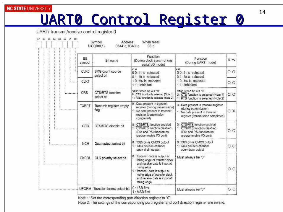
UART0 Control Register 0UART0 Control Register 0
15
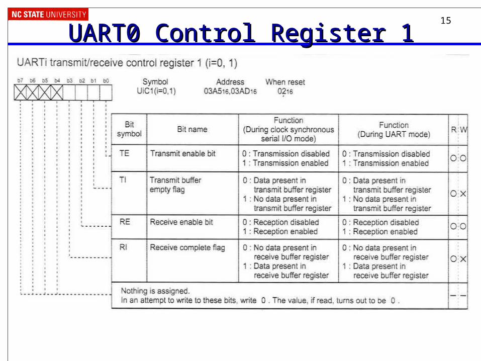
UART0 Control Register 1UART0 Control Register 1
16
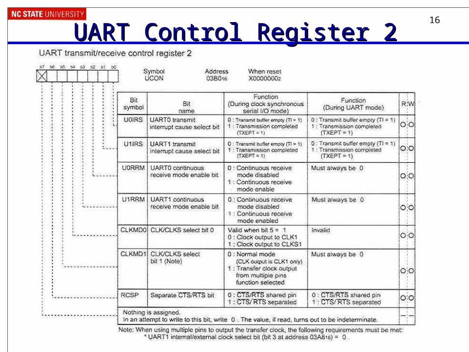
UART Control Register 2UART Control Register 2

17
UART0 Tx/Rx Mode RegisterUART0 Tx/Rx Mode Register
18
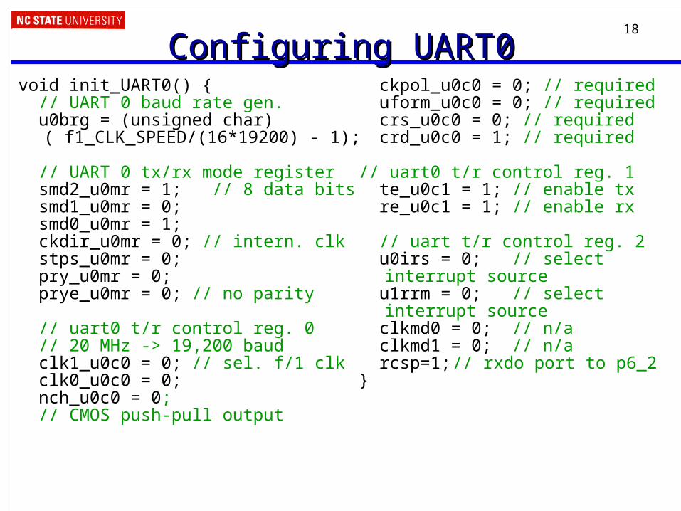
Configuring UART0Configuring UART0void init_UART0() { // UART 0 baud rate gen. u0brg = (unsigned char)
( f1_CLK_SPEED/(16*19200) - 1);
// UART 0 tx/rx mode register smd2_u0mr = 1; // 8 data bits smd1_u0mr = 0; smd0_u0mr = 1; ckdir_u0mr = 0; // intern. clk stps_u0mr = 0; pry_u0mr = 0; prye_u0mr = 0; // no parity
// uart0 t/r control reg. 0 // 20 MHz -> 19,200 baud clk1_u0c0 = 0; // sel. f/1 clk clk0_u0c0 = 0; nch_u0c0 = 0; // CMOS push-pull output
ckpol_u0c0 = 0; // required uform_u0c0 = 0; // required crs_u0c0 = 0; // required crd_u0c0 = 1; // required
// uart0 t/r control reg. 1 te_u0c1 = 1; // enable tx re_u0c1 = 1; // enable rx
// uart t/r control reg. 2 u0irs = 0; // select
interrupt source u1rrm = 0; // select
interrupt source clkmd0 = 0; // n/a clkmd1 = 0; // n/a rcsp=1;// rxdo port to p6_2 }
19
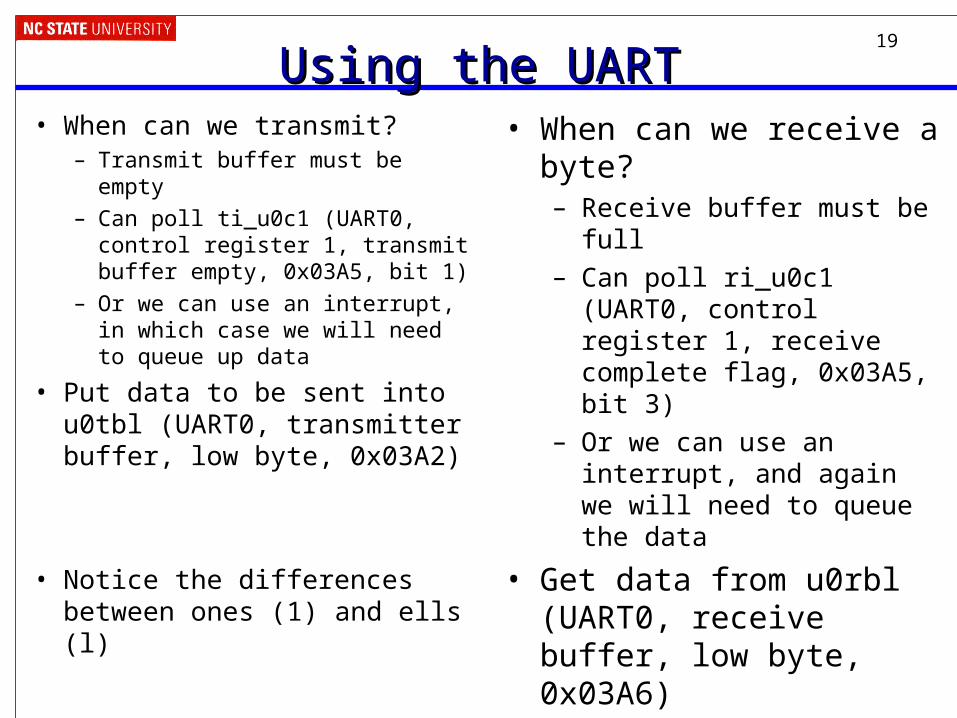
Using the UARTUsing the UART• When can we transmit?
– Transmit buffer must be empty
– Can poll ti_u0c1 (UART0, control register 1, transmit buffer empty, 0x03A5, bit 1)
– Or we can use an interrupt, in which case we will need to queue up data
• Put data to be sent into u0tbl (UART0, transmitter buffer, low byte, 0x03A2)
• Notice the differences between ones (1) and ells (l)
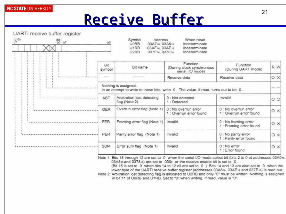
• When can we receive a byte?– Receive buffer must be full
– Can poll ri_u0c1 (UART0, control register 1, receive complete flag, 0x03A5, bit 3)
– Or we can use an interrupt, and again we will need to queue the data
• Get data from u0rbl (UART0, receive buffer, low byte, 0x03A6)

20
Transmit BufferTransmit Buffer
21
Receive BufferReceive Buffer

22
Example 1: Send Out Many CharactersExample 1: Send Out Many Characters• Send out every character and
symbol from ‘A’ to ‘z’ and then repeat
• Use polling to determine when transmit buffer is empty and can be reloaded
void demo1() { // polled transmit demo unsigned long ctr; char c='A'; while (1) { while (!ti_u0c1); // wait for
// transmit buffer empty
for (ctr=0; ctr<1000; ctr++);// delay so the letters// come out slowly
u0tbl = c; // load c into // transmit buffer
c++; // ! if (c>'z') c = 'A'; // wrap around }}

23
Example 2: Make the Code More ElegantExample 2: Make the Code More Elegant• Create a function to transmit a
null-terminated string
void demo2_ser_tx(far char * buf) {
// polled buffer transmit demo // transmit a null-terminated // string while (*buf) { while (!ti_u0c1); // wait for
// transmitter empty u0tbl = *buf; // load
// character into buffer
buf++; // increment buffer // pointer
}} void demo2() { while (1) { demo2_ser_tx("Testing!\n\r"); delay(100000); }}
24
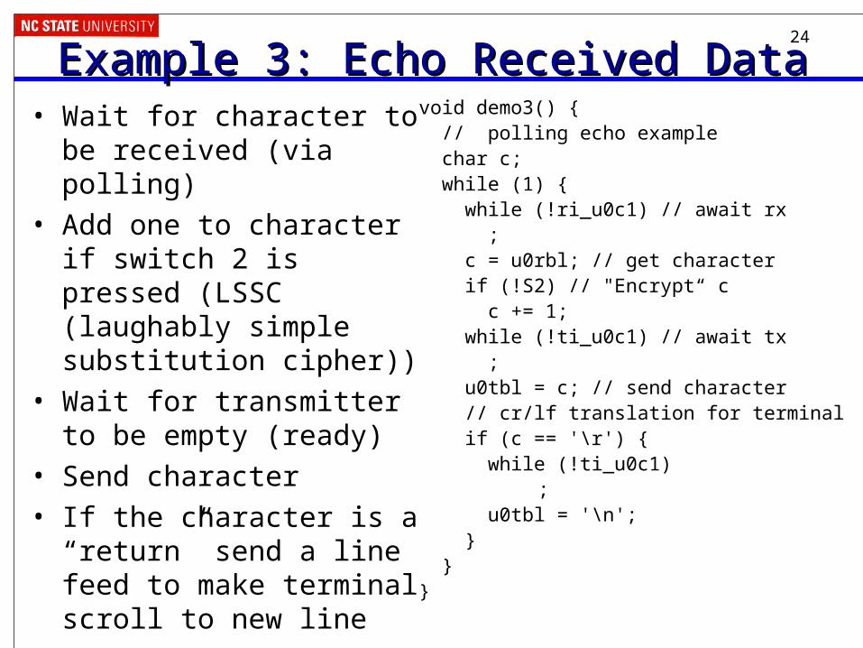
Example 3: Echo Received DataExample 3: Echo Received Data• Wait for character to be
received (via polling)
• Add one to character if switch 2 is pressed (LSSC (laughably simple substitution cipher))
• Wait for transmitter to be empty (ready)
• Send character
• If the character is a “return” send a line feed to make terminal scroll to new line
void demo3() { // polling echo example char c; while (1) { while (!ri_u0c1) // await rx ; c = u0rbl; // get character if (!S2) // "Encrypt“ c c += 1; while (!ti_u0c1) // await tx ; u0tbl = c; // send character // cr/lf translation for terminal if (c == '\r') { while (!ti_u0c1)
; u0tbl = '\n'; } }}

25
Bit Rate vs. Baud RateBit Rate vs. Baud Rate• Bit Rate: how many data bits are transmitted per second?• Baud Rate: how many symbols are transmitted per
second? – How many times does the communication channel change state
per second?
– A symbol may be represented by a voltage level, a sine wave’s frequency or phase, etc.
• These may be different– Extra symbols (channel changes) may be inserted for framing,
error detection, acknowledgment, etc. These reduce the bit rate
– A single symbol might encode more than one bit. This increases the bit rate.
• E.g. multilevel signaling, quadrature amplitude modulation, phase amplitude modulation, etc.
26
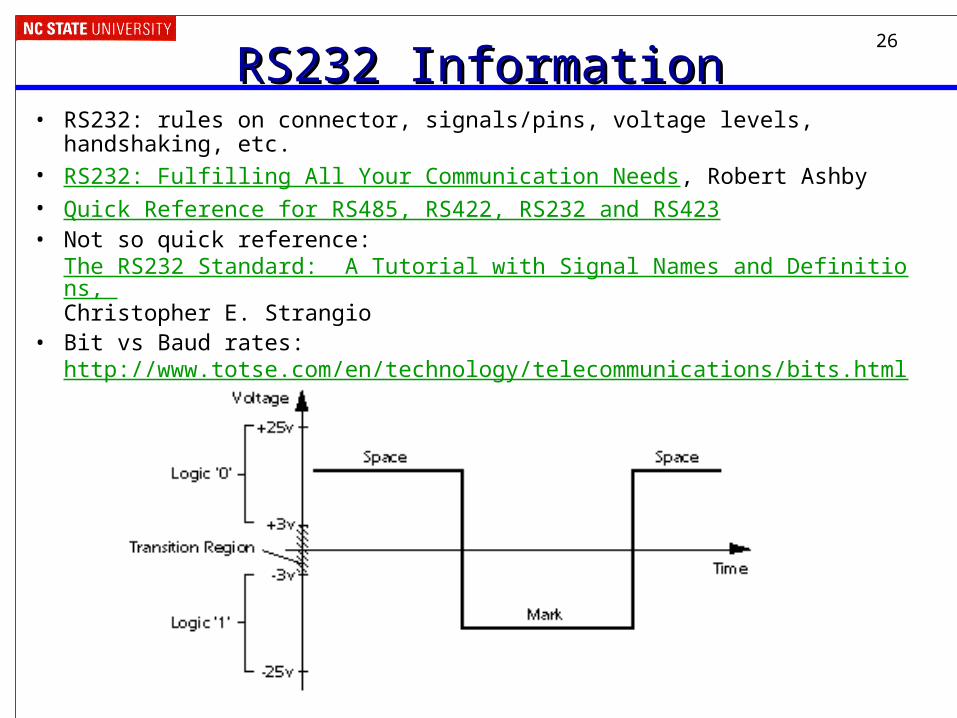
RS232 InformationRS232 Information• RS232: rules on connector, signals/pins, voltage levels, handshaking, etc.• RS232: Fulfilling All Your Communication Needs, Robert Ashby• Quick Reference for RS485, RS422, RS232 and RS423• Not so quick reference:
The RS232 Standard: A Tutorial with Signal Names and Definitions, Christopher E. Strangio
• Bit vs Baud rates: http://www.totse.com/en/technology/telecommunications/bits.html
27
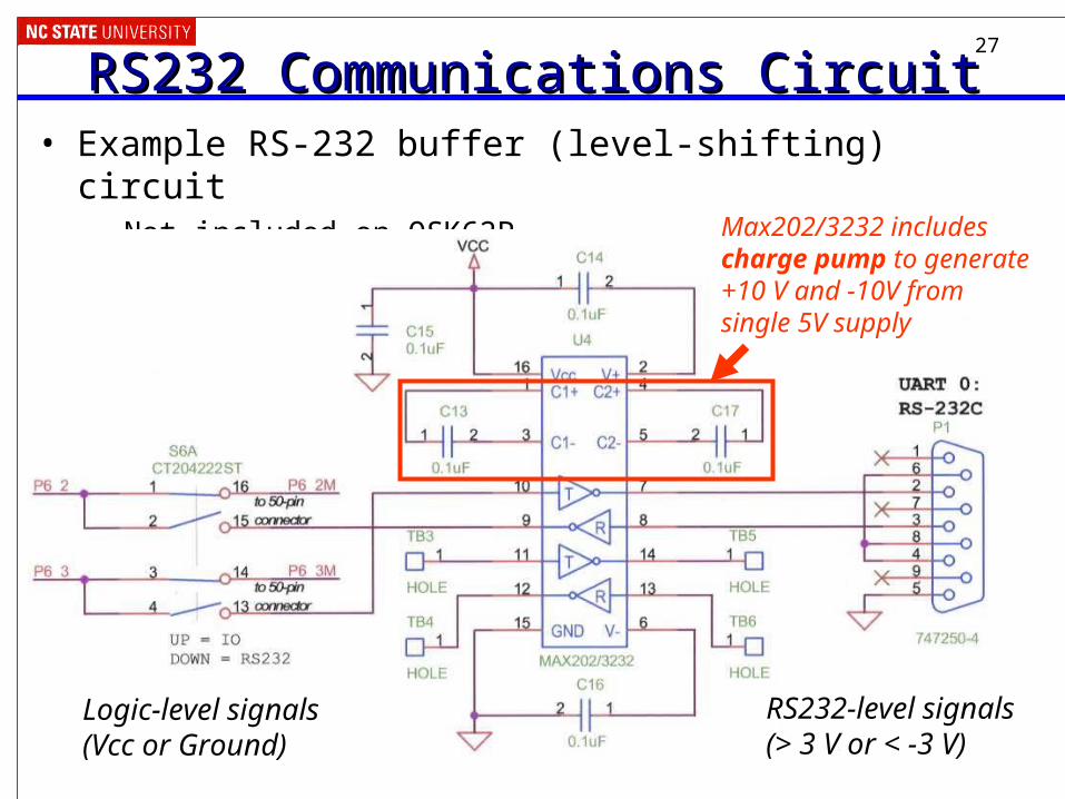
RS232 Communications CircuitRS232 Communications Circuit• Example RS-232 buffer (level-shifting) circuit
– Not included on QSK62PMax202/3232 includescharge pump to generate+10 V and -10V from single 5V supply
Logic-level signals(Vcc or Ground)
RS232-level signals(> 3 V or < -3 V)


