Download - POSIROT - asm-sensor · USA: . POSIROT

POSIROT® ®
Magnetic Angle Sensors PRAS3 Magnetic Angle Sensor Datasheet

POSIROT® PRAS3
DB-PRAS3-E-2017-01 2.0.0 | © ASM GmbH
2/21
www.asm-sensor.com USA: www.asmsensors.com
Copyright ASM GmbH Am Bleichbach 18-24 85452 Moosinning Germany
The information presented in this data sheet does not form part of any quotation or contract, is believed to be accurate and reliable and may be changed without notice. No liability will be accepted by ASM for any consequence of its use. Publication thereof does not convey nor imply any license under patent or industrial or intellectual property rights. Applications that are described herein for any of these products are for illustrative purpose only. ASM makes no representation or warranty that such applications will be suitable for the specified use without further testing or modification.

POSIROT® PRAS3
DB-PRAS3-E-2017-01 2.0.0 | © ASM GmbH
3/21
www.asm-sensor.com USA: www.asmsensors.com
Analog output ................................................................................................................................................... 4 Specifications ................................................................................................................................................. 4 Order code ..................................................................................................................................................... 5
Analog output, redundant ................................................................................................................................ 6 Specifications ................................................................................................................................................. 6 Order code ..................................................................................................................................................... 7
Dimensions ....................................................................................................................................................... 8 Version with shaft ........................................................................................................................................... 8 Version with hollow shaft................................................................................................................................ 9
Mounting plates .............................................................................................................................................. 10 Mounting possibilities PRAS2/PRDS2 and PRAS3/PRDS3 ........................................................................ 10
Output specification ....................................................................................................................................... 13 Analog output ............................................................................................................................................... 13 Analog output, redundant ............................................................................................................................. 16
Characteristics for magnetic angle sensors ................................................................................................ 18
Accessories ..................................................................................................................................................... 19 Connector cable M12, 4 pin ......................................................................................................................... 19 Connector cable M12, 8 pin ......................................................................................................................... 20
Deutsch connector ......................................................................................................................................... 21

POSIROT® PRAS3
DB-PRAS3-E-2017-01 2.0.0 | © ASM GmbH
4/21
www.asm-sensor.com USA: www.asmsensors.com
Analog output
Sensor features • Measurement range 0 ... 360°
• Protection class IP67/IP69
• Analog output
• Magnetic measurement principle
• With 10 mm shaft or 6 mm hollow shaft
• Housing: Aluminium
Specifications
Output Voltage 0.5 ... 10 V Voltage 0.5 ... 4.5 V Current 4 ... 20 mA, 3 wire
Measurement range 0 ... 15° to 0 ... 360° (in 15° increments)
Resolution 0.03% (60 ... 360°); 0.1% (15 ... 45°)
Repeatability ±0.03% (60 ... 360°); ±0.1% (15 ... 45°)
Linearity ±0.3% f.s. (typical)
Protection class IP67/IP69 (connector output with IP67/IP69 connector cable) IP67 (cable output)
Housing material Aluminium
Mounting Clamps, mounting plate
Connection 5-pin connector M12 (compatible to 4-pin connector) Cable, standard length 2 m Cable with Deutsch connector DT04
Temperature range -40 ... +85°C
Life cycle of bearings 100 x 106 revolutions (<1500 r.p.m.)
Revolutions per minute (mech.) 10.000 r.p.m.
Allowable shaft load 100 N radial / 100 N axial
Shock DIN EN 60068-2-27:2010, 100 g/11 ms, 100 shocks
Vibration DIN EN 60068-2-6:2008, 20 g 10 Hz-2 kHz, 10 cycles
Weight 250 g approx. (without cable)
EMC DIN EN 61326-1:2013
POSIROT® PRAS3
DB-PRAS3-E-2017-01 2.0.0 | © ASM GmbH
5/21
www.asm-sensor.com USA: www.asmsensors.com
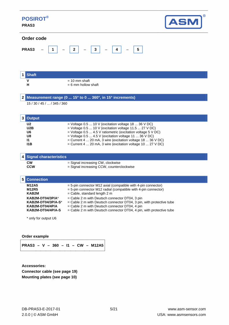
Order code
PRAS3 – 1 – 2 – 3 – 4 – 5
1 Shaft V = 10 mm shaft
H = 6 mm hollow shaft
2 Measurement range (0 ... 15° to 0 ... 360°, in 15° increments) 15 / 30 / 45 / ... / 345 / 360
3 Output U2 = Voltage 0.5 ... 10 V (excitation voltage 18 ... 36 V DC)
U2B = Voltage 0.5 ... 10 V (excitation voltage 11.5 ... 27 V DC) U6 = Voltage 0.5 ... 4.5 V ratiometric (excitation voltage 5 V DC) U8 = Voltage 0.5 ... 4.5 V (excitation voltage 11 ... 36 V DC) I1 = Current 4 ... 20 mA, 3 wire (excitation voltage 18 ... 36 V DC) I1B = Current 4 ... 20 mA, 3 wire (excitation voltage 10 ... 27 V DC)
4 Signal characteristics CW = Signal increasing CW, clockwise
CCW = Signal increasing CCW, counterclockwise
5 Connection
M12A5 = 5-pin connector M12 axial (compatible with 4-pin connector) M12R5 = 5-pin connector M12 radial (compatible with 4-pin connector) KAB2M = Cable, standard length 2 m
KAB2M-DT04/3P/A* = Cable 2 m with Deutsch connector DT04, 3 pin KAB2M-DT04/3P/A-S* = Cable 2 m with Deutsch connector DT04, 3 pin, with protective tube KAB2M-DT04/4P/A = Cable 2 m with Deutsch connector DT04, 4 pin KAB2M-DT04/4P/A-S = Cable 2 m with Deutsch connector DT04, 4 pin, with protective tube * only for output U6
Order example
PRAS3 – V – 360 – I1 – CW – M12A5
Accessories: Connector cable (see page 19) Mounting plates (see page 10)

POSIROT® PRAS3
DB-PRAS3-E-2017-01 2.0.0 | © ASM GmbH
6/21
www.asm-sensor.com USA: www.asmsensors.com
Analog output, redundant
Sensor features • Measurement range 0 ... 360°
• Protection class IP67/IP69
• Analog output, redundant
• Magnetic measurement principle
• With 10 mm shaft or 6 mm hollow shaft
• Housing: Aluminium
Specifications
Output Voltage 0.5 ... 10 V, redundant Voltage 0.5 ... 4.5 V, redundant Current 4 ... 20 mA, 3 wire, redundant
Measurement range 0 ... 15° to 0 ... 360° (in 15° increments)
Resolution 0.03% (60 ... 360°); 0.1% (15 ... 45°)
Repeatability ±0.03% (60 ... 360°); ±0.1% (15 ... 45°)
Linearity ±0.3% f.s. (typical)
Protection class IP67/IP69 (connector output with IP67/IP69 connector cable) IP67 (cable output)
Signal characteristics CW, CCW
Housing material Aluminium
Mounting Clamps, mounting plate
Connection 8-pin connector M12 Cable, standard length 2 m Cable with Deutsch connector DT04
Temperature range -40 ... +85°C
Life cycle of bearings 100 x 106 revolutions (<1500 r.p.m.)
Revolutions per minute (mech.) 10.000 r.p.m.
Allowable shaft load 100 N radial / 100 N axial
Shock DIN EN 60068-2-27:2010, 100 g/11 ms, 100 shocks
Vibration DIN EN 60068-2-6:2008, 20 g 10 Hz-2 kHz, 10 cycles
Weight 250 g approx. (without cable)
EMC DIN EN 61326-1:2013

POSIROT® PRAS3
DB-PRAS3-E-2017-01 2.0.0 | © ASM GmbH
7/21
www.asm-sensor.com USA: www.asmsensors.com
Order code
PRAS3 – 1 – 2 – 3 – 4 – 5
1 Shaft V = 10 mm shaft
H = 6 mm hollow shaft
2 Measurement range (0 ... 15° to 0 ... 360°, in 15° increments) 15 / 30 / 45 / ... / 345 / 360
3 Output U2R = Voltage 0.5 ... 10 V, redundant (excitation voltage 18 ... 36 V DC)
U6R = Voltage 0.5 ... 4.5 V ratiometric, redundant (excitation voltage 5 V DC) U8R = Voltage 0.5 ... 4.5 V, redundant (excitation voltage 11 ... 36 V DC) I1R = Current 4... 20 mA, 3 wire, redundant (excitation voltage 18 ... 36 V DC) (output I1R possible only with CW/CCW signal characteristics)
4 Signal characteristics CW/CCW = Signal 1 increasing clockwise, signal 2 increasing counterclockwise
CW/CW* = Signal 1 and signal 2 increasing clockwise CCW/CCW* = Signal 1 and signal 2 increasing counterclockwise * not available with output I1R
5 Connection
M12A8 = 8-pin connector M12 axial M12R8 = 8-pin connector M12 radial KAB2M = Cable, standard length 2 m
KAB2M-DT04/6P/A* = Cable 2 m with Deutsch connector DT04, 6 pin KAB2M-DT04/6P/A-S* = Cable 2 m with Deutsch connector DT04, 6 pin, with protective tube * only for output U6R
Order example
PRAS3 – V – 360 – U2R – CW/CCW – M12R8
Accessories: Connector cable (see page 20) Mounting plates (see page 10)
POSIROT® PRAS3
DB-PRAS3-E-2017-01 2.0.0 | © ASM GmbH
8/21
www.asm-sensor.com USA: www.asmsensors.com
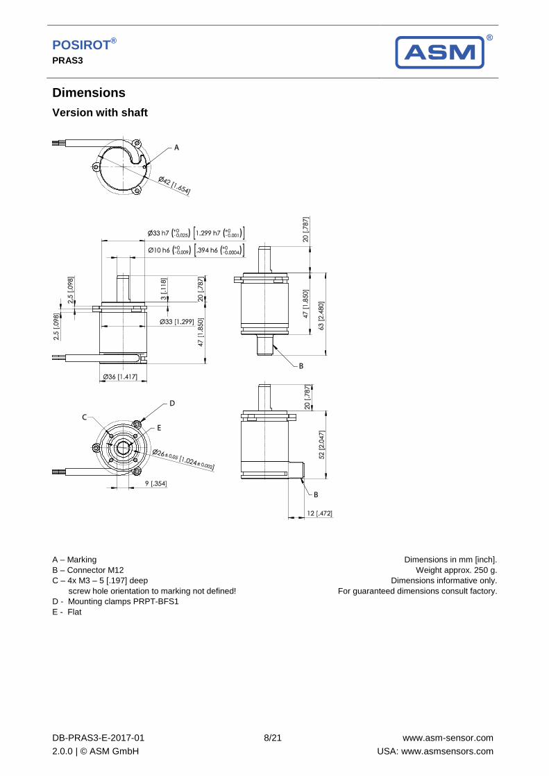
Dimensions
Version with shaft
A – Marking B – Connector M12 C – 4x M3 – 5 [.197] deep screw hole orientation to marking not defined! D - Mounting clamps PRPT-BFS1 E - Flat
Dimensions in mm [inch]. Weight approx. 250 g.
Dimensions informative only. For guaranteed dimensions consult factory.
POSIROT® PRAS3
DB-PRAS3-E-2017-01 2.0.0 | © ASM GmbH
9/21
www.asm-sensor.com USA: www.asmsensors.com
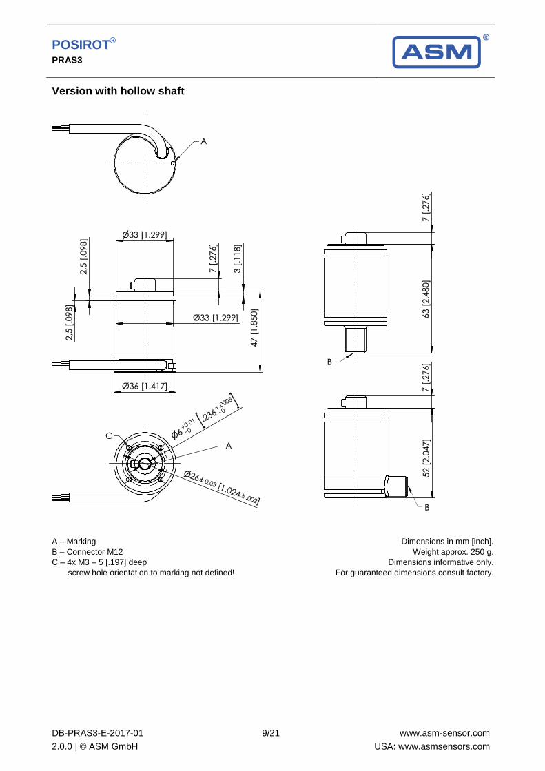
Version with hollow shaft
A – Marking B – Connector M12 C – 4x M3 – 5 [.197] deep screw hole orientation to marking not defined!
Dimensions in mm [inch]. Weight approx. 250 g.
Dimensions informative only. For guaranteed dimensions consult factory.
POSIROT® PRAS3
DB-PRAS3-E-2017-01 2.0.0 | © ASM GmbH
10/21
www.asm-sensor.com USA: www.asmsensors.com
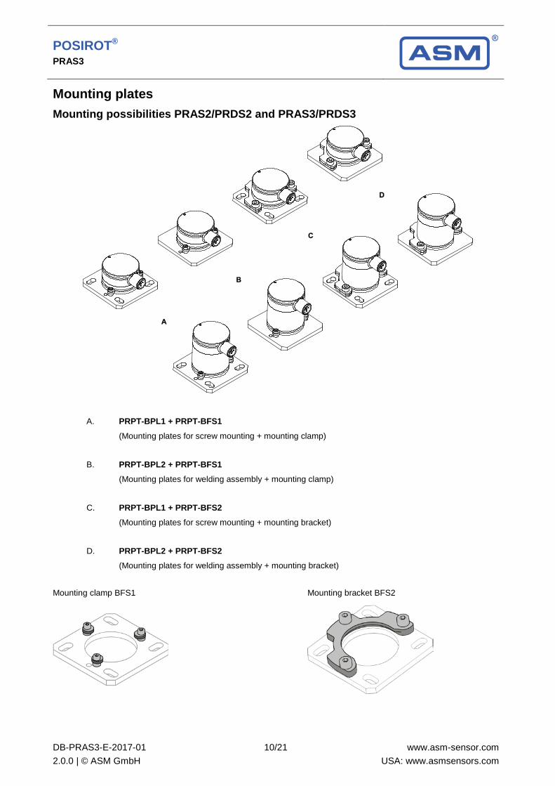
Mounting plates
Mounting possibilities PRAS2/PRDS2 and PRAS3/PRDS3
A. PRPT-BPL1 + PRPT-BFS1
(Mounting plates for screw mounting + mounting clamp)
B. PRPT-BPL2 + PRPT-BFS1 (Mounting plates for welding assembly + mounting clamp)
C. PRPT-BPL1 + PRPT-BFS2
(Mounting plates for screw mounting + mounting bracket)
D. PRPT-BPL2 + PRPT-BFS2 (Mounting plates for welding assembly + mounting bracket)
Mounting clamp BFS1 Mounting bracket BFS2

POSIROT® PRAS3
DB-PRAS3-E-2017-01 2.0.0 | © ASM GmbH
11/21
www.asm-sensor.com USA: www.asmsensors.com
PRPT-BPL1 (Screw mounting) In combination with the mounting clamps PRPT-BFS1 (3 x M2.5) or in combination with the mounting bracket PRPT-BFS2 (3 x M4).
Dimensions in mm [inch]. Weight 30 g approx. Dimensions informative only. For guaranteed dimensions please consult factory.
PRPT-BPL2 (Welding assembly) In combination with the mounting clamps PRPT-BFS1 (3 x M2.5) or in combination with the mounting bracket PRPT-BFS2 (3 x M4).
Dimensions in mm [inch]. Weight 30 g approx. Dimensions informative only. For guaranteed dimensions please consult factory.
POSIROT® PRAS3
DB-PRAS3-E-2017-01 2.0.0 | © ASM GmbH
12/21
www.asm-sensor.com USA: www.asmsensors.com
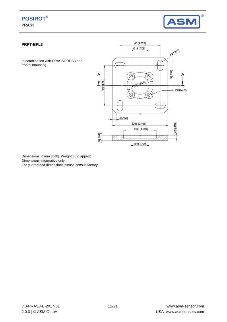
PRPT-BPL3 In combination with PRAS3/PRDS3 and frontal mounting.
Dimensions in mm [inch]. Weight 30 g approx. Dimensions informative only. For guaranteed dimensions please consult factory.

POSIROT® PRAS3
DB-PRAS3-E-2017-01 2.0.0 | © ASM GmbH
13/21
www.asm-sensor.com USA: www.asmsensors.com
Output specification
Analog output
U2 Voltage output 0.5 ... 10 V
Excitation voltage 18 … 36 V DC
Excitation current typical 10 mA max. 15 mA
Output voltage 0.5 ... 10 V DC Output current 2 mA max. Measuring rate 1 kHz standard
Stability (temperature) ±50 x 10-6 / °C f.s. (typical for 90° … 360°) ±100 x 10-6 / °C f.s. (typical for <90°)
Protection Reverse polarity, short circuit Operating temperature -40 … +85 °C EMC DIN EN 61326-1:2013
U2B Voltage output 0.5 ... 10 V
Excitation voltage 11.5 … 27 V DC
Excitation current typical 12 mA max. 16 mA
Output voltage 0,5 ... 10 V DC Output current 2 mA max. Measuring rate 1 kHz standard
Stability (temperature) ±50 x 10-6 / °C f.s. (typical for 90° … 360°) ±100 x 10-6 / °C f.s. (typical for <90°)
Protection Reverse polarity, short circuit Operating temperature -40 … +85 °C EMC DIN EN 61326-1:2013
U6 Voltage output 10 … 90 % ratiometric
Excitation voltage 5 V DC ±10 %
Excitation current typical 8 mA max. 12 mA
Output voltage 10 … 90 % of the excitation voltage Output current 2 mA max. Measuring rate 1 kHz standard
Stability (temperature) ±50 x 10-6 / °C f.s. (typical for 90° … 360°) ±100 x 10-6 / °C f.s. (typical for <90°)
Protection Reverse polarity, short circuit Operating temperature -40 … +85 °C EMC DIN EN 61326-1:2013
POSIROT® PRAS3
DB-PRAS3-E-2017-01 2.0.0 | © ASM GmbH
14/21
www.asm-sensor.com USA: www.asmsensors.com
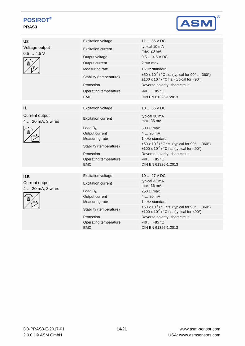
U8 Voltage output 0.5 … 4.5 V
Excitation voltage 11 … 36 V DC
Excitation current typical 10 mA max. 20 mA
Output voltage 0.5 … 4.5 V DC Output current 2 mA max. Measuring rate 1 kHz standard
Stability (temperature) ±50 x 10-6 / °C f.s. (typical for 90° … 360°) ±100 x 10-6 / °C f.s. (typical for <90°)
Protection Reverse polarity, short circuit Operating temperature -40 … +85 °C EMC DIN EN 61326-1:2013
I1 Excitation voltage 18 … 36 V DC
Current output 4 … 20 mA, 3 wires
Excitation current typical 30 mA max. 35 mA
Load RL 500 Ω max. Output current 4 … 20 mA Measuring rate 1 kHz standard
Stability (temperature) ±50 x 10-6 / °C f.s. (typical for 90° … 360°) ±100 x 10-6 / °C f.s. (typical for <90°)
Protection Reverse polarity, short circuit Operating temperature -40 … +85 °C EMC DIN EN 61326-1:2013
I1B Current output 4 … 20 mA, 3 wires
Excitation voltage 10 … 27 V DC
Excitation current typical 32 mA max. 36 mA
Load RL 250 Ω max. Output current 4 … 20 mA Measuring rate 1 kHz standard
Stability (temperature) ±50 x 10-6 / °C f.s. (typical for 90° … 360°) ±100 x 10-6 / °C f.s. (typical for <90°)
Protection Reverse polarity, short circuit Operating temperature -40 … +85 °C EMC DIN EN 61326-1:2013

POSIROT® PRAS3
DB-PRAS3-E-2017-01 2.0.0 | © ASM GmbH
15/21
www.asm-sensor.com USA: www.asmsensors.com
Signal diagram
U2, U2B U6 U8
I1, I1B
Excitation +
Signal +
GND
Signal wiring (connector and cable output)
Signal Connector pin no. Cable color View to the sensor connector
Excitation + 1 brown
Signal 2 white GND 3 blue Do not connect! 4 black Do not connect! 5 grey
3-wire current 4...20 mA interface: GND has to be connected!
Deutsch connector DT04
DT04/3P/A DT04/4P/A

POSIROT® PRAS3
DB-PRAS3-E-2017-01 2.0.0 | © ASM GmbH
16/21
www.asm-sensor.com USA: www.asmsensors.com
Analog output, redundant
U2R Voltage output 0.5 ... 10 V
Excitation voltage 18 … 36 V DC
Excitation current typical 10 mA max. 15 mA per channel
Output voltage 0.5 ... 10 V DC Output current 2 mA max. Measuring rate 1 kHz Standard
Stability (temperature) ±50 x 10-6 / °C f.s. (typical for 90° … 360°) ±100 x 10-6 / °C f.s. (typical for <90°)
Protection Reverse polarity, short circuit Operating temperature -40 … +85 °C EMC DIN EN 61326-1:2013
U6R Voltage output 10 … 90 % ratiometric
Excitation voltage 5 V DC ±10 %
Excitation current typical 8 mA max. 12 mA per channel
Output voltage 10 … 90 % of the excitation voltage Output current 2 mA max. Measuring rate 1 kHz standard
Stability (temperature) ±50 x 10-6 / °C f.s. (typical for 90° … 360°) ±100 x 10-6 / °C f.s. (typical for <90°)
Protection Reverse polarity, short circuit Operating temperature -40 … +85 °C EMC EN 61326-1:2013
U8R Voltage output 0.5 … 4.5 V
Excitation voltage 11 … 36 V DC Excitation current typical 10 mA
max. 20 mA per channel Output voltage 0.5 … 4,5 V DC Output current 2 mA max. Measuring rate 1 kHz standard Stability (temperature) ±50 x 10-6 / °C f.s. (typical for 90° … 360°)
±100 x 10-6 / °C f.s. (typical for <90°) Protection Reverse polarity, short circuit Operating temperature -40 … +85 °C EMC DIN EN 61326-1:2013
POSIROT® PRAS3
DB-PRAS3-E-2017-01 2.0.0 | © ASM GmbH
17/21
www.asm-sensor.com USA: www.asmsensors.com
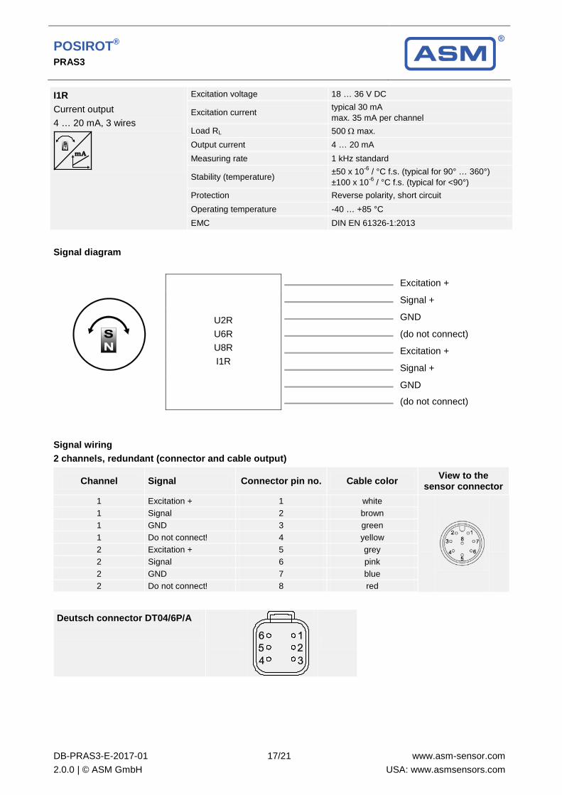
I1R Current output 4 … 20 mA, 3 wires
Excitation voltage 18 … 36 V DC
Excitation current typical 30 mA max. 35 mA per channel
Load RL 500 Ω max. Output current 4 … 20 mA Measuring rate 1 kHz standard
Stability (temperature) ±50 x 10-6 / °C f.s. (typical for 90° … 360°) ±100 x 10-6 / °C f.s. (typical for <90°)
Protection Reverse polarity, short circuit Operating temperature -40 … +85 °C EMC DIN EN 61326-1:2013
Signal diagram
U2R U6R U8R I1R
Excitation +
Signal +
GND
(do not connect)
Excitation +
Signal +
GND
(do not connect)
Signal wiring 2 channels, redundant (connector and cable output)
Channel Signal Connector pin no. Cable color View to the sensor connector
1 Excitation + 1 white
1 Signal 2 brown 1 GND 3 green 1 Do not connect! 4 yellow 2 Excitation + 5 grey 2 Signal 6 pink 2 GND 7 blue 2 Do not connect! 8 red
Deutsch connector DT04/6P/A

POSIROT® PRAS3
DB-PRAS3-E-2017-01 2.0.0 | © ASM GmbH
18/21
www.asm-sensor.com USA: www.asmsensors.com
Characteristics for magnetic angle sensors
Output signal CW (clockwise increasing)
Output signal CCW (counterclockwise increasing)
Example angular range 90°
Example angular range 360°
A – Marking B – Measurement range [°]

POSIROT® PRAS3
DB-PRAS3-E-2017-01 2.0.0 | © ASM GmbH
19/21
www.asm-sensor.com USA: www.asmsensors.com
Accessories
Connector cable M12, 4 pin (angular coupling) shielded connector
Suitable for 5-pin sensor connectors
The 4-core screened cable is supplied with a mating 4-pin 90° M12 connector at one end and 4 wires at the other end. Available lengths are 2 m, 5 m and 10 m. Wire: cross sectional area 0.34 mm2
Cable diameter: 5.6 ±0.2 mm
Order code KAB - xM - M12/4F/W - LITZE
IP69: KAB - xM - M12/4F/W/69K - LITZE xM = length in m
Connector cable M12, 4 pin (straight coupling) shielded connector
Suitable for 5-pin sensor connectors
The 4-core screened cable is supplied with a mating 4-pin M12 connector at one end and 4 wires at the other end. Available lengths are 2 m, 5 m and 10 m. Wire: cross sectional area 0.34 mm2
Cable diameter: 5.6 ±0.2 mm Order code KAB - xM - M12/4F/G - LITZE
IP69: KAB - xM - M12/4F/G/69K - LITZE xM = length in m
Signal wiring M12, 4 pin
Plug connection / cable color
1 2 3 4
brown white blue black
Applicable for cable carriers Maximum movement speed 3 m/s Maximum acceleration 5 m/s2 Minimum bending radius 10 x cable diameter
POSIROT® PRAS3
DB-PRAS3-E-2017-01 2.0.0 | © ASM GmbH
20/21
www.asm-sensor.com USA: www.asmsensors.com
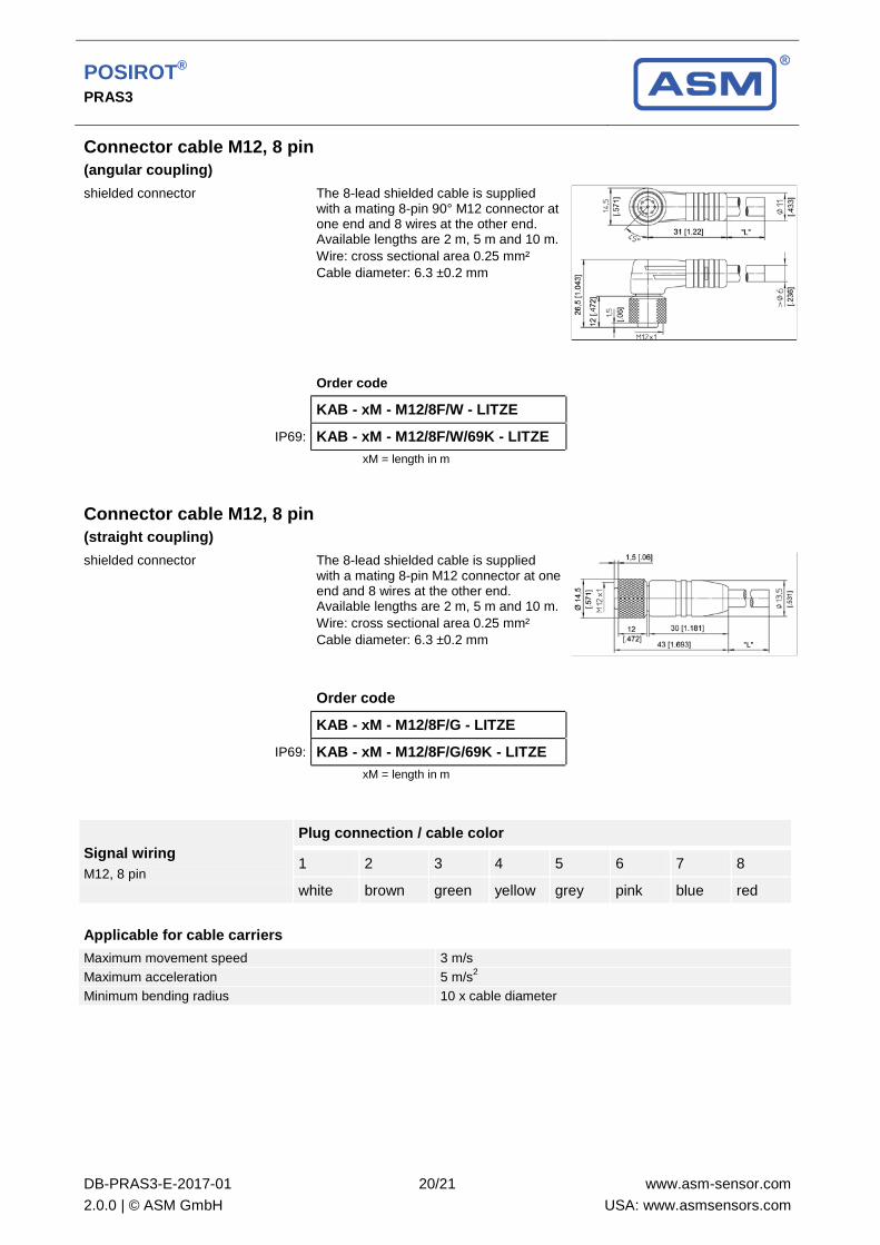
Connector cable M12, 8 pin (angular coupling) shielded connector The 8-lead shielded cable is supplied
with a mating 8-pin 90° M12 connector at one end and 8 wires at the other end. Available lengths are 2 m, 5 m and 10 m. Wire: cross sectional area 0.25 mm² Cable diameter: 6.3 ±0.2 mm
Order code KAB - xM - M12/8F/W - LITZE
IP69: KAB - xM - M12/8F/W/69K - LITZE xM = length in m
Connector cable M12, 8 pin (straight coupling) shielded connector The 8-lead shielded cable is supplied
with a mating 8-pin M12 connector at one end and 8 wires at the other end. Available lengths are 2 m, 5 m and 10 m. Wire: cross sectional area 0.25 mm² Cable diameter: 6.3 ±0.2 mm
Order code KAB - xM - M12/8F/G - LITZE
IP69: KAB - xM - M12/8F/G/69K - LITZE xM = length in m
Signal wiring M12, 8 pin
Plug connection / cable color
1 2 3 4 5 6 7 8
white brown green yellow grey pink blue red
Applicable for cable carriers Maximum movement speed 3 m/s Maximum acceleration 5 m/s2 Minimum bending radius 10 x cable diameter
POSIROT® PRAS3
DB-PRAS3-E-2017-01 2.0.0 | © ASM GmbH
21/21
www.asm-sensor.com USA: www.asmsensors.com
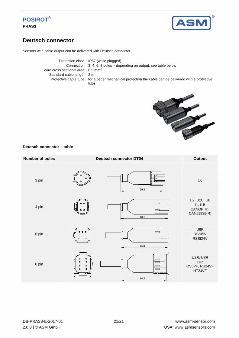
Deutsch connector Sensors with cable output can be delivered with Deutsch connector.
Protection class: Connection:
Wire cross sectional area: Standard cable length: Protective cable tube:
IP67 (while plugged) 3, 4, 6, 8 poles – depending on output, see table below 0.5 mm2 2 m for a better mechanical protection the cable can be delivered with a protective tube
Deutsch connector – table
Number of poles Deutsch connector DT04 Output
3 pin
U6
4 pin
U2, U2B, U8 I1, I1B
CANOP(R), CANJ1939(R)
6 pin
U6R
RSSI5V RSSI24V
8 pin
U2R, U8R I1R
RS5VF, RS24VF HT24VF

POSIROT® ®
Magnetic Angle Encoders
PRDS3
Magnetic Angle Encoder
Datasheet

POSIROT® PRDS3
DB-PRDS3-E-2017-01
2.0.0 | © ASM GmbH
2/30
www.asm-sensor.com
USA: www.asmsensors.com
Copyright
ASM GmbH Am Bleichbach 18-24 85452 Moosinning Germany
The information presented in this data sheet does not form part of any quotation or contract, is believed to be accurate and reliable and may be changed without notice. No liability will be accepted by ASM for any consequence of its use. Publication thereof does not convey nor imply any license under patent or industrial or intellectual property rights. Applications that are described herein for any of these products are for illustrative purpose only.
ASM makes no representation or warranty that such applications will be suitable for the specified use without further testing or modification.
POSIROT® PRDS3
DB-PRDS3-E-2017-01
2.0.0 | © ASM GmbH
3/30
www.asm-sensor.com
USA: www.asmsensors.com
Incremental output ........................................................................................................................................... 4
Specifications ................................................................................................................................................. 4
Order code ..................................................................................................................................................... 5
Digital output SSI .............................................................................................................................................. 6
Specifications ................................................................................................................................................. 6
Order code ..................................................................................................................................................... 7
Digital output CAN ............................................................................................................................................ 8
Specifications ................................................................................................................................................. 8
Order code ..................................................................................................................................................... 9
Dimensions ..................................................................................................................................................... 10
Version with hollow shaft.............................................................................................................................. 10
Version with shaft ......................................................................................................................................... 11
Mounting plates .............................................................................................................................................. 12
Mounting possibilities PRAS2/PRDS2 and PRAS3/PRDS3 ........................................................................ 12
Incremental output ......................................................................................................................................... 15
SSI output ........................................................................................................................................................ 19
Digital output CANopen ................................................................................................................................. 21
Digital output CAN SAE J1939 ...................................................................................................................... 23
Characteristics for magnetic angle sensors ................................................................................................ 27
Accessories ..................................................................................................................................................... 28
Connector cable M12, 8 pin ......................................................................................................................... 28
Connector/bus cable M12, 5 pin CAN-Bus .................................................................................................. 29
T-connector for bus cable M12, 5 pin CAN-Bus .......................................................................................... 29
Terminating resistor M12, 5 pin CAN-Bus ................................................................................................... 29
Deutsch connector ......................................................................................................................................... 30

POSIROT® PRDS3
DB-PRDS3-E-2017-01
2.0.0 | © ASM GmbH
4/30
www.asm-sensor.com
USA: www.asmsensors.com
Incremental output
Sensor features
• Measurement range 0 ... 360°
• Protection class IP67/IP69
• Incremental output
• Magnetic measurement principle
• With 10 mm shaft or 6 mm hollow shaft
• Housing: Aluminium
Specifications
Output Incremental encoder output RS422-/HTL compatible, filtered output
Measurement range 0 ... 360°
Resolution (pulses per revolution) 256 or 1024
Linearity ±1% (typical)
Protection class IP67/IP69 (connector output with IP67/IP69 connector cable) IP67 (cable output)
Housing material Aluminium
Mounting Clamps, mounting plate
Connection 5-pin connector M12 Cable, standard length 2 m
Temperature range -40 ... +85°C
Life cycle of bearings 100 x 106 revolutions (<1500 r.p.m.)
Revolutions per minute (mech.) 10.000 r.p.m.
Allowable shaft load 100 N radial / 100 N axial
Shock DIN EN 60068-2-27:2010, 100 g/11 ms, 100 shocks
Vibration DIN EN 60068-2-6:2008, 20 g 10 Hz-2 kHz, 10 cycles
Weight 250 g approx. (without cable)
EMC DIN EN 61326-1:2013

POSIROT® PRDS3
DB-PRDS3-E-2017-01
2.0.0 | © ASM GmbH
5/30
www.asm-sensor.com
USA: www.asmsensors.com
Order code
PRDS3 – 1 – 2 – 3 – 4
1 Shaft
V = Shaft 10 mm H = Hollow shaft 6 mm
2 Resolution (pulses per revolution)
256 / 1024
3 Output
RS5VF = RS422 compatible output with excitation 5 V DC, filtered output RS24VF = RS422 compatible output with excitation 10 ... 36 V, filtered output HT24VF = HTL compatible output with excitation 18 ... 36 V, filtered output
4 Connection
M12A8 = 8-pin connector M12, axial M12R8 = 8-pin connector M12, radial KAB2M = Cable, standard length 2 m
Order example
PRDS3 – V – 1024 – HT24VF – M12R8
Accessories:
Connector cable (see page 28)
Mounting plates (see page 12)

POSIROT® PRDS3
DB-PRDS3-E-2017-01
2.0.0 | © ASM GmbH
6/30
www.asm-sensor.com
USA: www.asmsensors.com
Digital output SSI
Sensor features
• Measurement range 0 ... 360°
• Protection class IP67/IP69
• Digital output SSI
• Magnetic measurement principle
• With 10 mm shaft or 6 mm hollow shaft
• Housing: Aluminium
Specifications
Output Synchronous serial SSI
Measurement range 0 ... 360°
Resolution 12 Bit (4096 steps) per revolution
Repeatability ±0.1° (typical)
Linearity ±1% (typical)
Protection class IP67/IP69 (connector output with IP67/IP69 connector cable) IP67 (cable output)
Material Aluminium
Mounting Clamps, mounting plate
Connection 8-pin connector M12 Cable, standard length 2 m Cable with Deutsch connector DT04
Temperature range -40 ... +85°C
Life cycle of bearings 100 x 106 revolutions (<1500 r.p.m.)
Revolutions per minute (mech.) 10.000 r.p.m.
Allowable shaft load 100 N radial / 100 N axial
Shock DIN EN 60068-2-27:2010, 100 g/11 ms, 100 shocks
Vibration DIN EN 60068-2-6:2008, 20 g 10 Hz-2 kHz, 10 cycles
Weight 250 g approx. (without cable)
EMC DIN EN 61326-1:2013

POSIROT® PRDS3
DB-PRDS3-E-2017-01
2.0.0 | © ASM GmbH
7/30
www.asm-sensor.com
USA: www.asmsensors.com
Order code
PRDS3 – 1 – 2 – 3 – 4
1 Shaft
V = Shaft 10 mm H = Hollow shaft 6 mm
2 Output
RSSI5V = Synchronous serial output with excitation 5 V DC RSSI24V = Synchronous serial output with excitation 10 ... 36 V
3 Code characteristics
CW = Signal increasing CW, clockwise CCW = Signal increasing CCW, counterclockwise
4 Connection
M12A8 = 8-pin connector M12, axial M12R8 = 8-pin connector M12, radial KAB2M = Cable, standard length 2 m KAB2M-DT04/6P/A = Cable 2 m with Deutsch connector DT04, 6 pin KAB2M-DT04/6P/A-S = Cable 2 m with Deutsch connector DT04, 6 pin, with protective tube
Order example
PRDS3 – V – RSSI24V – CW – M12R8
Accessories:
Connector cable (see page 28)
Mounting plates (see page 12)

POSIROT® PRDS3
DB-PRDS3-E-2017-01
2.0.0 | © ASM GmbH
8/30
www.asm-sensor.com
USA: www.asmsensors.com
Digital output CAN
Sensor features
• Measurement range 0 ... 360°
• Protection class IP67/IP69
• Digital output CAN
• Magnetic measurement principle
• With 10 mm shaft or 6 mm hollow shaft
• Housing: Aluminium
Specifications
Output CANopen (CiA 301-V4.02/406-V3.2) CAN SAE J1939
Measurement range 0 ... 360°
Resolution 0.05° max.
Linearity ±1% (typical)
Protection class IP67/IP69 (connector output with IP67/IP69 connector cable) IP67 (cable output)
Material Aluminium
Mounting Clamps, mounting plate
Connection 5-pin connector M12 Cable with Deutsch connector DT04
Temperature range -40 ... +85°C
Life cycle of bearings 100 x 106 revolutions (<1500 r.p.m.)
Revolutions per minute (mech.) 10.000 r.p.m.
Allowable shaft load 100 N radial / 100 N axial
Shock DIN EN 60068-2-27:2010, 100 g/11 ms, 100 shocks
Vibration DIN EN 60068-2-6:2008, 20 g 10 Hz-2 kHz, 10 cycles
Weight 250 g approx. (without cable)
EMC DIN EN 61326-1:2013
POSIROT® PRDS3
DB-PRDS3-E-2017-01
2.0.0 | © ASM GmbH
9/30
www.asm-sensor.com
USA: www.asmsensors.com
Order code
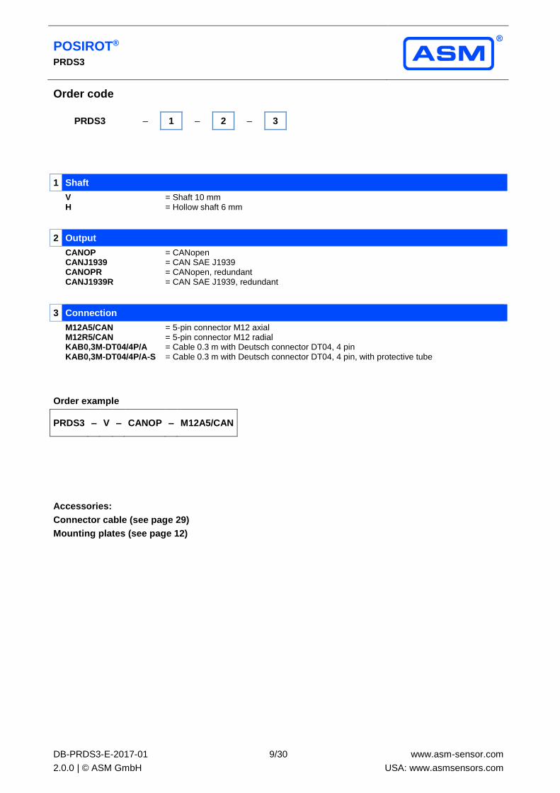
PRDS3 – 1 – 2 – 3
1 Shaft
V = Shaft 10 mm H = Hollow shaft 6 mm
2 Output
CANOP = CANopen CANJ1939 = CAN SAE J1939 CANOPR = CANopen, redundant CANJ1939R = CAN SAE J1939, redundant
3 Connection
M12A5/CAN = 5-pin connector M12 axial M12R5/CAN = 5-pin connector M12 radial KAB0,3M-DT04/4P/A = Cable 0.3 m with Deutsch connector DT04, 4 pin KAB0,3M-DT04/4P/A-S = Cable 0.3 m with Deutsch connector DT04, 4 pin, with protective tube
Order example
PRDS3 – V – CANOP – M12A5/CAN
Accessories:
Connector cable (see page 29)
Mounting plates (see page 12)
POSIROT® PRDS3
DB-PRDS3-E-2017-01
2.0.0 | © ASM GmbH
10/30
www.asm-sensor.com
USA: www.asmsensors.com
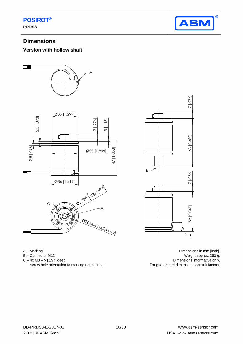
Dimensions
Version with hollow shaft
A – Marking
B – Connector M12
C – 4x M3 – 5 [.197] deep
screw hole orientation to marking not defined!
Dimensions in mm [inch].
Weight approx. 250 g.
Dimensions informative only.
For guaranteed dimensions consult factory.

POSIROT® PRDS3
DB-PRDS3-E-2017-01
2.0.0 | © ASM GmbH
11/30
www.asm-sensor.com
USA: www.asmsensors.com
Version with shaft
A – Marking
B – Connector M12
C – 4x M3 – 5 [.197] deep
screw hole orientation to marking not defined!
D - Mounting clamps PRPT-BFS1
E - Flat
Dimensions in mm [inch].
Weight approx. 250 g.
Dimensions informative only.
For guaranteed dimensions consult factory.

POSIROT® PRDS3
DB-PRDS3-E-2017-01
2.0.0 | © ASM GmbH
12/30
www.asm-sensor.com
USA: www.asmsensors.com
Mounting plates
Mounting possibilities PRAS2/PRDS2 and PRAS3/PRDS3
A. PRPT-BPL1 + PRPT-BFS1
(Mounting plates for screw mounting + mounting clamp)
B. PRPT-BPL2 + PRPT-BFS1
(Mounting plates for welding assembly + mounting clamp)
C. PRPT-BPL1 + PRPT-BFS2
(Mounting plates for screw mounting + mounting bracket)
D. PRPT-BPL2 + PRPT-BFS2
(Mounting plates for welding assembly + mounting bracket)
Mounting clamp BFS1 Mounting bracket BFS2

POSIROT® PRDS3
DB-PRDS3-E-2017-01
2.0.0 | © ASM GmbH
13/30
www.asm-sensor.com
USA: www.asmsensors.com
PRPT-BPL1
(Screw mounting)
In combination with the mounting clamps PRPT-BFS1 (3 x M2.5) or in combination with the mounting bracket PRPT-BFS2 (3 x M4).
Dimensions in mm [inch]. Weight 30 g approx.
Dimensions informative only.
For guaranteed dimensions please consult factory.
PRPT-BPL2
(Welding assembly)
In combination with the mounting clamps PRPT-BFS1 (3 x M2.5) or in combination with the mounting bracket PRPT-BFS2 (3 x M4).
Dimensions in mm [inch]. Weight 30 g approx.
Dimensions informative only.
For guaranteed dimensions please consult factory.

POSIROT® PRDS3
DB-PRDS3-E-2017-01
2.0.0 | © ASM GmbH
14/30
www.asm-sensor.com
USA: www.asmsensors.com
PRPT-BPL3
In combination with PRAS3/PRDS3 and
frontal mounting.
Dimensions in mm [inch]. Weight 30 g approx.
Dimensions informative only.
For guaranteed dimensions please consult factory.

POSIROT® PRDS3
DB-PRDS3-E-2017-01
2.0.0 | © ASM GmbH
15/30
www.asm-sensor.com
USA: www.asmsensors.com
Incremental output
RS5V(F)/RS24V(F) Interface EIA RS-422
Incremental Excitation voltage RS5V(F): 5 V DC ±10 %
RS24V(F): 10 ... 36 V DC
Excitation current 100 mA max., depending on the load
Pulse frequency <500 kHz
Output signals A, A, B, B, Z, Z Push-Pull
Output current 10 mA max.
Stability (temperature) ±50 x 10-6 / °C f.s. (typical)
Operating temperature -40 ... +85 °C
Protection Short circuit
EMC DIN EN 61326-1:2013
Output signals
Excitation +
Excitation GND
Signal A
Signal A
Signal B
Signal B
Signal Z (ref. puls)
Signal Z
Unfiltered output RS5V / RS24V
A preferred maximum pulse frequency has to be defined within the product code. This will take account for limited bandwidth of downstream counter.
Filtered output RS5VF / RS24VF
Option for filtered jitter free position value. The filter does not introduce velocity or acceleration error.
POSIROT® PRDS3
DB-PRDS3-E-2017-01
2.0.0 | © ASM GmbH
16/30
www.asm-sensor.com
USA: www.asmsensors.com
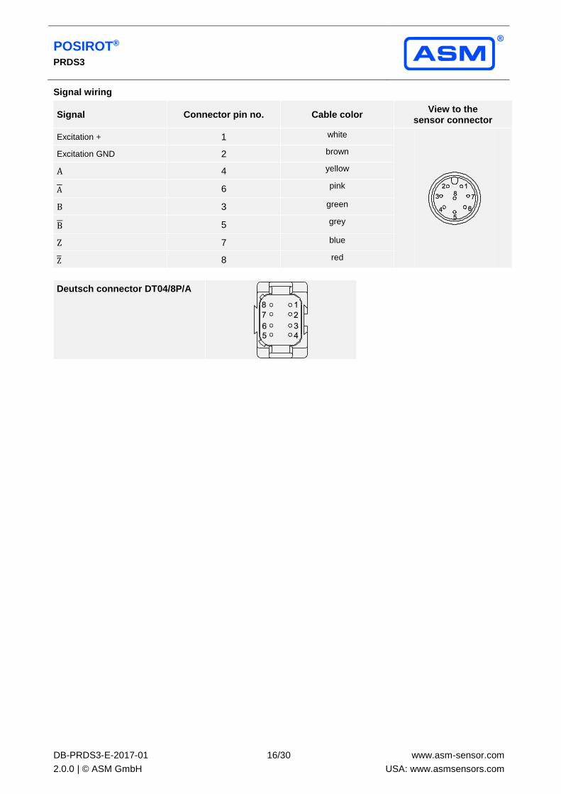
Signal wiring
Signal Connector pin no. Cable color View to the
sensor connector
Excitation + 1 white
Excitation GND 2 brown
A 4 yellow
A 6 pink
B 3 green
B 5 grey
Z 7 blue
Z 8 red
Deutsch connector DT04/8P/A

POSIROT® PRDS3
DB-PRDS3-E-2017-01
2.0.0 | © ASM GmbH
17/30
www.asm-sensor.com
USA: www.asmsensors.com
HT24V(F) Interface HTL
Incremental Excitation voltage 18 ... 36 V DC
Excitation current 100 mA max., depending on the load
Pulse frequency <500 kHz
Output signals A, A, B, B, Z, Z Push-Pull
Output current 10 mA max.
Stability (temperature) ±50 x 10-6 / °C f.s. (typical)
Operating temperature -40 ... +85 °C
Protection Short circuit
EMC DIN EN 61326-1:2013
Output signals
Excitation+
Excitation GND
Signal A
Signal A
Signal B
Signal B
Signal Z (ref. puls)
Signal Z
Unfiltered output HT24V
A preferred maximum pulse frequency has to be defined within the product code. This will take account for limited
bandwidth of downstream counter.
Filtered output HT24VF
Option for filtered jitter free position value. The filter does not introduce velocity or acceleration error.

POSIROT® PRDS3
DB-PRDS3-E-2017-01
2.0.0 | © ASM GmbH
18/30
www.asm-sensor.com
USA: www.asmsensors.com
Signal wiring
Output signals Connector pin no. Cable color View to the sensor
connector
Excitation + 1 white
Excitation GND 2 brown
A 4 yellow
A 6 pink
B 3 green
B 5 grey
Z 7 blue
Z 8 red
Deutsch connector DT04/8P/A

POSIROT® PRDS3
DB-PRDS3-E-2017-01
2.0.0 | © ASM GmbH
19/30
www.asm-sensor.com
USA: www.asmsensors.com
SSI output
RSSI5V/RSSI24V Interface EIA RS-422
Synchronous serial SSI Excitation voltage RSSI5V: 5 V DC ±10%
RSSI24V: 10 ... 36 V DC
Excitation current 100 mA max. without load
Clock frequency 100 kHz ... 500 kHz
Code Gray-Code, continuous progression, 12 bit
Delay between pulse trains 20 µs min.
Stability (temperature) ±50 x 10-6 / °C f.s. (typical)
Operating temperature -40 ... +85 °C
Protection Short circuit
EMC EN 61326-1:2013
Data format
(Train of 13 pulses)
Recommended
processing circuit
Transmission rate Cable length Baud rate Note:
Extension of the cable length will reduce the maximum transmission rate. The
signals CLOCK /CLOCK and DATA/DATA must be connected in a twisted pair cable, shielded
per pair and common.
50 m 100 - 1000 kHz
100 m 100 - 300 kHz
POSIROT® PRDS3
DB-PRDS3-E-2017-01
2.0.0 | © ASM GmbH
20/30
www.asm-sensor.com
USA: www.asmsensors.com
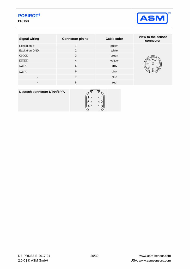
Signal wiring Connector pin no. Cable color View to the sensor
connector
Excitation + 1 brown
Excitation GND 2 white
CLOCK 3 green
CLOCK 4 yellow
DATA 5 grey
DATA 6 pink
- 7 blue
- 8 red
Deutsch connector DT04/6P/A

POSIROT® PRDS3
DB-PRDS3-E-2017-01
2.0.0 | © ASM GmbH
21/30
www.asm-sensor.com
USA: www.asmsensors.com
Digital output CANopen
CANOP CAN Specification ISO 11898, Basic and Full CAN 2.0 B
CANopen Communication profile CANopen CiA 301 V 4.02, Slave
Device profile Encoder CiA 406 V 3.2
Configuration services Layer Setting Service (LSS), CiA Draft Standard 305 (transmission rate, node id)
Error Control Node Guarding, Heartbeat, Emergency Message
Node ID Default: 127; programmable via LSS or SDO
PDO 3 TxPDO, 0 RxPDO, static mapping
PDO Modes Event-/Time triggered, Remote-request, Sync cyclic/acyclic
SDO 1 server, 0 Client
CAM 8 cams
Certified Yes
Transmission rates 50 kBaud to 1 MBaud, default: 125 kBaud; programmable via LSS or SDO
Bus connection M12 connector, 5 pin
Integrated bus terminating resistor Adjustable by the customer
Bus, galvanic isolated No
Specifications
Excitation voltage 8 ... 36 V DC
Excitation current 20 mA typical at 24 V DC
40 mA typical at 12 V DC, 80 mA max.
Resolution 0.05° max.
Linearity 1° (optional 0.25°)
Measuring rate 1 kHz (asynchronous)
Stability (temperature) ±50 x 10-6/°C f.s. (typical)
Repeatability 1 LSB
Operating temperature See specification of the respective sensor
Protection Reverse polarity, short circuit
Dielectric strength 1 kV (V AC, 50 Hz, 1 min.)
EMC DIN EN 61326-1:2013
Signal wiring
Signal Connector pin no. Cable color View to the sensor
connector
Shield 1 brown
Excitation + 2 white
GND 3 blue
CAN-H 4 black
CAN-L 5 grey
Signal wiring
Deutsch connector
DT04/4P/A
Signal Connector pin no. View to the sensor
connector
Excitation+ 1
CAN-H 2
GND 3
CAN-L 4

POSIROT® PRDS3
DB-PRDS3-E-2017-01
2.0.0 | © ASM GmbH
22/30
www.asm-sensor.com
USA: www.asmsensors.com
CANOPR CAN Specification ISO 11898, Basic and Full CAN 2.0 B
CANopen Communication profile CANopen CiA 301 V 4.02, Slave
Device profile Encoder CiA 406 V 3.2
Configuration services Layer Setting Service (LSS), CiA Draft Standard 305 (transmission rate, node id)
Error Control Node Guarding, Heartbeat, Emergency Message
Node ID Default: 127 and 126; programmable via LSS or SDO
PDO 3 TxPDO, 0 RxPDO, static mapping
PDO Modes Event-/Time triggered, Remote-request, Sync cyclic/acyclic
SDO 1 server, 0 Client
CAM 8 cams
Certified Yes
Transmission rates 50 kBaud to 1 MBaud, default: 125 kBaud; programmable via LSS or SDO
Bus connection M12 connector, 5 pin
Integrated bus terminating resistor adjustable by the customer
Bus, galvanic isolated No
Specifications
Excitation voltage 8 ... 36 V DC
Excitation current 40 mA typical at 24 V DC
80 mA typical at 12 V DC, 120 mA max.
Resolution 0.05° max.
Linearity 1° (0.25° optional)
Measuring rate 1 kHz (asynchronous)
Stability (temperature) ±50 x 10-6/°C f.s. (typical)
Repeatability 1 LSB
Operating temperature See specification of the respective sensor
Protection Reverse polarity, short circuit
Dielectric strength 1 kV (V AC, 50 Hz, 1 min.)
EMC DIN EN 61326-1:2013
Signal wiring
Signal Connector pin no. Cable color View to the sensor
connector
Shield 1 brown
Excitation + 2 white
GND 3 blue
CAN-H 4 black
CAN-L 5 grey
Signal wiring
Deutsch connector
DT04/4P/A
Signal Connector pin no. View to the sensor
connector
Excitation+ 1
CAN-H 2
GND 3
CAN-L 4

POSIROT® PRDS3
DB-PRDS3-E-2017-01
2.0.0 | © ASM GmbH
23/30
www.asm-sensor.com
USA: www.asmsensors.com
Digital output CAN SAE J1939
CANJ1939 CAN Specification ISO 11898, Basic and Full CAN 2.0 B
CAN SAE J1939 Transceiver 24V-compliant, not isolated
Communication profile SAE J1939
Baud Rate 250 kbit/s
Internal termination resistor adjustable by the customer
Address Default 247d, configurable
NAME Fields Arbitrary address capable 1 Yes
Industry group 0 Global
Vehicle system 7Fh (127d) Non specific
Vehicle system instance 0
Function FFh (255d) Non specific
Function instance 0
ECU instance 0
Manufacturer 145h (325d) Manufacturer ID
Identity number 0nnn Serial number 21 bit
Parameter Group
Numbers (PGN)
Configuration data PGN EF00h Proprietary-A
(PDU1 peer-to-peer)
Process data PGN FFnnh Proprietary-B
(PDU2 broadcast);
nn Group Extension (PS) configurable
Specifications
Excitation voltage 8 ... 36 V DC
Excitation current 20 mA typical at 24 V DC
40 mA typical at 12 V DC, 80 mA max.
Resolution 0.05° max.
Linearity 1° (0.25° optional)
Measuring rate 1 kHz (asynchronous)
Stability (temperature) ±50 x 10-6/°C f.s. (typical)
Repeatability 1 LSB
Operating temperature See specification of the respective sensor
Protection Reverse polarity, short circuit
Dielectric strength 1 kV (V AC, 50 Hz, 1 min.)
EMV DIN EN 61326-1:2013
Signal wiring Signal Connector pin no.
View to the sensor connector
Shield 1
Excitiation + 2
GND 3
CAN-H 4
CAN-L 5

POSIROT® PRDS3
DB-PRDS3-E-2017-01
2.0.0 | © ASM GmbH
24/30
www.asm-sensor.com
USA: www.asmsensors.com
Signal wiring
Deutsch connector
DT04/4P/A
Signal Connector pin no. View to the sensor
connector
Excitation+ 1
CAN-H 2
GND 3
CAN-L 4

POSIROT® PRDS3
DB-PRDS3-E-2017-01
2.0.0 | © ASM GmbH
25/30
www.asm-sensor.com
USA: www.asmsensors.com
CANJ1939R CAN Specification ISO 11898, Basic and Full CAN 2.0 B
CAN SAE J1939 Transceiver 24V-compliant, not isolated
Communication profile SAE J1939
Baud Rate 250 kbit/s
Internal termination resistor Adjustable by the customer
Address Default 247d and 246d, configurable
NAME Fields Arbitrary address capable 1 Yes
Industry group 0 Global
Vehicle system 7Fh (127d) Non specific
Vehicle system instance 0
Function FFh (255d) Non specific
Function instance 0
ECU instance 0
Manufacturer 145h (325d) Manufacturer ID
Identity number 0nnn Serial number 21 bit
Parameter Group
Numbers (PGN)
Configuration data PGN EF00h
Proprietary-A
(PDU1 peer-to-peer)
Process data PGN FFnnh Proprietary-B
(PDU2 broadcast);
nn Group Extension (PS) configurable
Specifications
Excitation voltage 8 ... 36 V DC
Excitation current 40 mA typical at 24 V DC
80 mA typical at 12 V DC, 120 mA max.
Resolution 0.05° max.
Linearity 1° (0.25° optional)
Measuring rate 1 kHz (asynchronous)
Stability (temperature) ±50 x 10-6/°C f.s. (typical)
Repeatability 1 LSB
Operating temperature See specification of the respective sensor
Protection Reverse polarity, short circuit
Dielectric strength 1 kV (V AC, 50 Hz, 1 min.)
EMV DIN EN 61326-1:2013
Signal wiring Signal Connector Pin no. Cable color
View to the sensor connector
Shield 1 brown
Excitiation + 2 white
GND 3 blue
CAN-H 4 black
CAN-L 5 grey

POSIROT® PRDS3
DB-PRDS3-E-2017-01
2.0.0 | © ASM GmbH
26/30
www.asm-sensor.com
USA: www.asmsensors.com
Signal wiring
Deutsch connector
DT04/4P/A
Signal Connector pin no. View to the sensor
connector
Excitation+ 1
CAN-H 2
GND 3
CAN-L 4

POSIROT® PRDS3
DB-PRDS3-E-2017-01
2.0.0 | © ASM GmbH
27/30
www.asm-sensor.com
USA: www.asmsensors.com
Characteristics for magnetic angle sensors
Output signal CW
(clockwise increasing)
Output signal CCW
(counterclockwise increasing)
Example angular range 90°
Example angular range 360°
A – Marking
B – Measurement range [°]

POSIROT® PRDS3
DB-PRDS3-E-2017-01
2.0.0 | © ASM GmbH
28/30
www.asm-sensor.com
USA: www.asmsensors.com
Accessories
Connector cable M12, 8 pin
(angular coupling)
shielded connector The 8-lead shielded cable is supplied with a mating 8-pin 90° M12 connector at one end and 8 wires at the other end. Available lengths are 2 m, 5 m and 10 m.
Wire: cross sectional area 0.25 mm²
Cable diameter: 6.3 ±0.2 mm
Order code
KAB - xM - M12/8F/W - LITZE
IP69: KAB - xM - M12/8F/W/69K - LITZE
xM = length in m
Connector cable M12, 8 pin
(straight coupling)
shielded connector The 8-lead shielded cable is supplied with a mating 8-pin M12 connector at one end and 8 wires at the other end.
Available lengths are 2 m, 5 m and 10 m.
Wire: cross sectional area 0.25 mm²
Cable diameter: 6.3 ±0.2 mm
Order code
KAB - xM - M12/8F/G - LITZE
IP69: KAB - xM - M12/8F/G/69K - LITZE
xM = length in m
Signal wiring
M12, 8 pin
Plug connection / cable color
1 2 3 4 5 6 7 8
white brown green yellow grey pink blue red
Applicable for cable carriers
Maximum movement speed 3 m/s
Maximum acceleration 5 m/s2
Minimum bending radius 10 x cable diameter
POSIROT® PRDS3
DB-PRDS3-E-2017-01
2.0.0 | © ASM GmbH
29/30
www.asm-sensor.com
USA: www.asmsensors.com
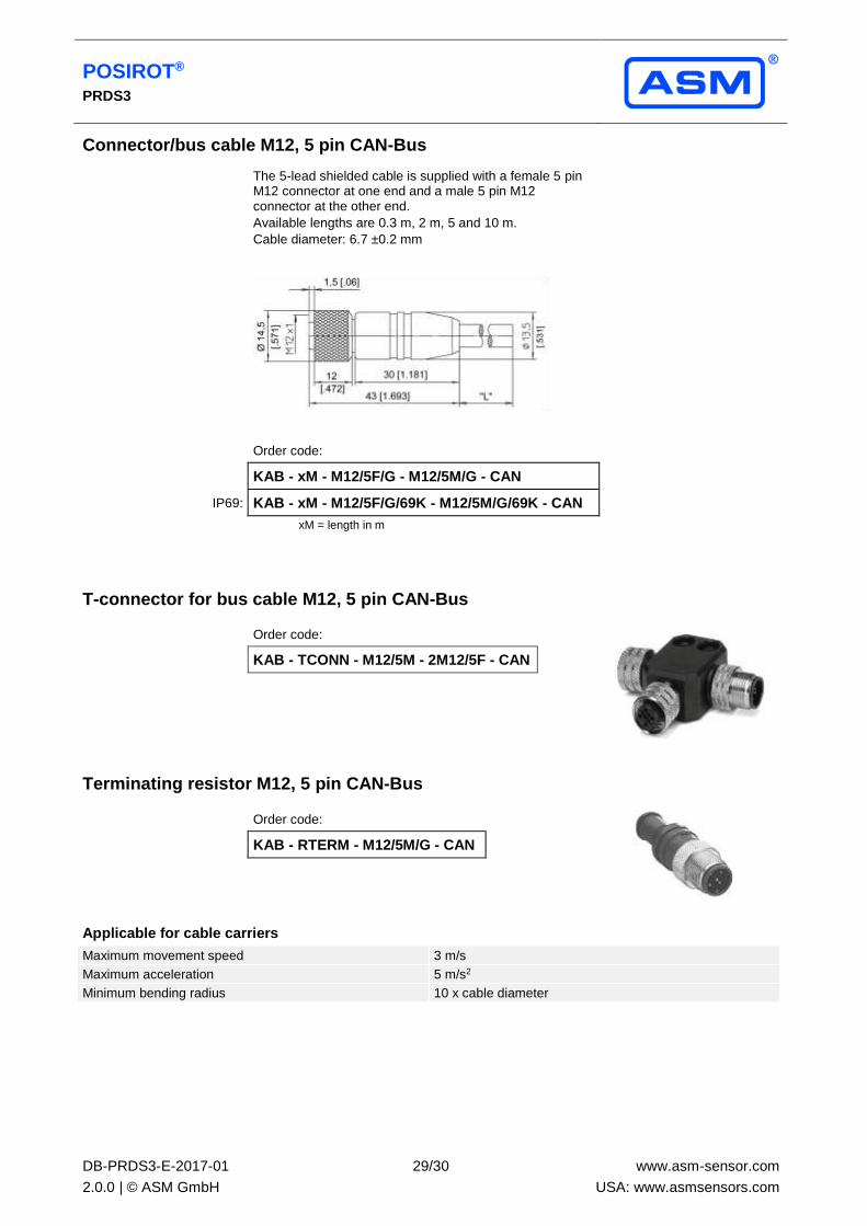
Connector/bus cable M12, 5 pin CAN-Bus
The 5-lead shielded cable is supplied with a female 5 pin M12 connector at one end and a male 5 pin M12 connector at the other end.
Available lengths are 0.3 m, 2 m, 5 and 10 m.
Cable diameter: 6.7 ±0.2 mm
Order code:
KAB - xM - M12/5F/G - M12/5M/G - CAN
IP69: KAB - xM - M12/5F/G/69K - M12/5M/G/69K - CAN
xM = length in m
T-connector for bus cable M12, 5 pin CAN-Bus
Order code:
KAB - TCONN - M12/5M - 2M12/5F - CAN
Terminating resistor M12, 5 pin CAN-Bus
Order code:
KAB - RTERM - M12/5M/G - CAN
Applicable for cable carriers
Maximum movement speed 3 m/s
Maximum acceleration 5 m/s2
Minimum bending radius 10 x cable diameter

POSIROT® PRDS3
DB-PRDS3-E-2017-01
2.0.0 | © ASM GmbH
30/30
www.asm-sensor.com
USA: www.asmsensors.com
Deutsch connector
Sensors with cable output can be delivered with Deutsch connector.
Protection class:
Connection:
Wire cross sectional area:
Standard cable length:
Protective cable tube:
IP67 (while plugged)
3, 4, 6, 8 poles – depending on output, see table below
0.5 mm2
2 m
for a better mechanical protection the cable can be delivered with a protective tube
Deutsch connector – table
Number of poles Deutsch connector DT04 Output
3 pin
U6
4 pin
U2, U2B, U8
I1, I1B
CANOP(R), CANJ1939(R)
6 pin
U6R
RSSI5V
RSSI24V
8 pin
U2R, U8R
I1R RS5VF, RS24VF
HT24VF


