
Powell GIS™ Type G81 Switchgear
Application Guide for Powell GIS IEC Switchgear
Powered by Safety®
Powered by Safety®
TABLE OF CONTENTSIntroduction 1
Switchgear Design 2 Standards 2 Normal Operating Conditions 2 Environmental Conditions 2 Degree of Protection 2 General Description 3 Section Design and Compartments 3 Low Voltage Compartment 3
Vacuum Circuit Breaker 4 General 4 Classification 5 Control and Auxiliary Circuit 5 Interlocking 5 Switchgear Accessories 5
Ratings 6
Section Component Identification 77
Typical Section Views 8
Guide Specification 10
Contact Us 16
Powered by Safety®
1
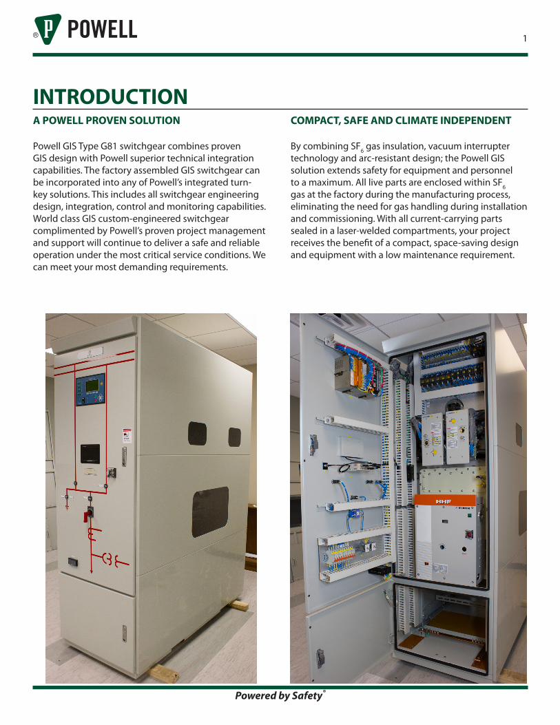
A POWELL PROVEN SOLUTION
Powell GIS Type G81 switchgear combines proven GIS design with Powell superior technical integration capabilities. The factory assembled GIS switchgear can be incorporated into any of Powell’s integrated turn-key solutions. This includes all switchgear engineering design, integration, control and monitoring capabilities. World class GIS custom-engineered switchgear complimented by Powell’s proven project management and support will continue to deliver a safe and reliable operation under the most critical service conditions. We can meet your most demanding requirements.
COMPACT, SAFE AND CLIMATE INDEPENDENT
By combining SF6 gas insulation, vacuum interrupter technology and arc-resistant design; the Powell GIS solution extends safety for equipment and personnel to a maximum. All live parts are enclosed within SF6 gas at the factory during the manufacturing process, eliminating the need for gas handling during installation and commissioning. With all current-carrying parts sealed in a laser-welded compartments, your project receives the benefit of a compact, space-saving design and equipment with a low maintenance requirement.
INTRODUCTION
Powered by Safety®
2
DEGREE OF PROTECTION
Protection against entry of hazardous parts and water according to the IEC 62271-200 and IEC 60529 following degree of protection.
High Voltage Live Parts IP65 Dust-tight and protected
against water jet
Low Voltage Compartment IP4X
Protected for a diameter or strips of a thickness greater than 1.0 mm
GENERAL DESCRIPTION
The switchgear is an indoor gas-insulated and metal-enclosed 3-phase cubicle design with segregated SF6 insulated compartments for circuit breaker and bus systems. Configurations are available with single or double bus systems. It is suitable for local and remote control.
The high voltage elements consist of two or three gas-tight stainless steel tanks (SUS 304L), built as a sealed pressure system. Each of the gas compartments has a filling valve, gas monitoring by means of a pressure sensor, and its own pressure relief system.
With non bolted plug-in bus bar connections, Powell GIS does not require any handling of SF6 gas at the jobsite. The power cables enter from the bottom and connect to the switchgear by means of plug-in connectors. An optional test socket is available for cable testing and current and voltage injection. The cable compartment has a pressure relief system leading to the pressure relief duct.
The switchgear is designed for a maximum leakage rate of 0.1% per year. The gas tanks are constructed utilizing state-of-the art manufacturing techniques out of laser cut and welded stainless steel.
The operation safety and insulation properties (power frequency voltage and BIL) are still maintained even in case the gas drops to atmospheric pressure at sea level.
SWITCHGEAR DESIGNSTANDARDS
Powell GIS™ Type G81 switchgear is manufactured and has been design tested to following IEC standards.
Switchgear Powell GIS IEC 62271-1IEC 62271-200
Device
Circuit Breaker IEC 62271-1003 Position Switch IEC 62271-102
Fuse Combination Switch IEC 62271-105
Degree of Protection IEC 60529
SF6 GasSpecification IEC 60376
Diagnosis Guide IEC 60480
Insulation Transformer
Current Transformer IEC 6044-1Voltage Transformer IEC 6044-2
NORMAL OPERATING CONDITIONS
The rated current is based on the normal operating conditions for indoor switchgear with an ambient temperature range from -5 °C to +40 °C.
If the ambient temperature is higher than +40 oC, the permissible current is different from the rated current (please consult factory for appropriate derating details). However, the maximum ambient temperature should not be higher than +55 oC.
ENVIRONMENTAL CONDITIONS
All live parts in the circuit breaker and bus bar compartments are sealed by gas-tight enclosure of IP65. These compartments are safe to touch and suitable for applications under aggressive ambient conditions such as salt, humidity, dust and condensation. The compartment design provides protection from small animals.
SF6 gas is a non-flammable, non-toxic and a non-ozone depleting insulating medium.
GENERAL DESCRIPTION (CONT.)
For operator safety the switchgear has an active and passive protection system against internal faults in each partitioned gas compartment.
The passive safety section ensures that hot gases generated in the vent of an internal arc fault are directed via pressure relief disks from each SF6 compartment and into the pressure relief duct system. The pressure relief duct is guided outside of the building or vented to an area to prevent harm to personnel. This maximizes safety to personnel and risk of fire. Switchgear gas tank components have been type tested to IEC 62271-200, IAC class BFLR at 40kA, 1s.
The temperature-compensated sensors for pressure measurement are used to continuously monitor the SF6 gas tank compartment pressure. Theses sensors provide operator warning in the event of pressures outside the normal operating window.
The high voltage switchgear components do not require maintenance for the life of the equipment when applied under normal operating conditions. The circuit breaker drive mechanisms are accessible for inspection and maintenance and do not require opening any portion of the gas enclosed components.
Pressure relief duct must be provided for all high voltage SF6 gas filled compartments. This duct may not utilize the cable connection space or be vented below the switchgear through a false floor or similar design.
SECTION DESIGN AND COMPARTMENTS
The switchgear sections are divided into the following compartments:1. Core sealed SF6 gas compartment containing vacuum circuit breaker, current transformers and current/voltage sensors.2. Bus sealed SF6 gas compartment with built-in 2 or 3 position switches.3. Open air cable termination compartment including provisions for conventional voltage transformer plug-in connection.4. Open air low voltage compartment to house secondary control devices, meters, relays and other monitoring equipment.
Powered by Safety®
3
LOW VOLTAGE COMPARTMENT
The low voltage compartment is a self-contained assembly and all operating mechanisms are motorized. Manual emergency operation and mechanical position indicators are provided. Normal operation such as switching, reading of measurements and messaging is possible without special instruction or operator training.
The low voltage compartment can also contain a custom-engineered Powell Automation control and monitoring solution designed specifically to meet your application.
Powell provides custom-engineered automation solutions ranging from transfer schemes to power management and load-shed applications. Our proven experience includes oil and gas production, refineries, power generation, mining, and data centers. Around the world today, varying degrees of control and monitoring philosophies are rapidly being implemented. Our experience and application knowledge of intelligent electronic devices (IEDs) and networking solutions allows us to engineer a modern, open architecture system for your control and monitoring needs.
Powell also provides embedded resources to ensure a successful project integration and delivery. Contact our application team today!
Powered by Safety®
4
VACUUM CIRCUIT BREAKERGENERAL
The circuit breakers are three-pole vacuum interrupter type and comply with IEC Publication 62271-100.
Within the core gas compartment the vacuum circuit breaker is stationary mounted. Type test certificates can be supplied upon request.
The high voltage part of the circuit breaker is maintenance-free for life time under normal operating conditions as specified by IEC 60694. The circuit breaker drive mechanism does require periodic maintenance and is accessible from the front of the switchgear without having to enter or depressure any SF6 gas filled compartment. First maintenance interval occurs after 10 years service.
All circuit breakers are subjected to routine testing in accordance with IEC 62271-100.
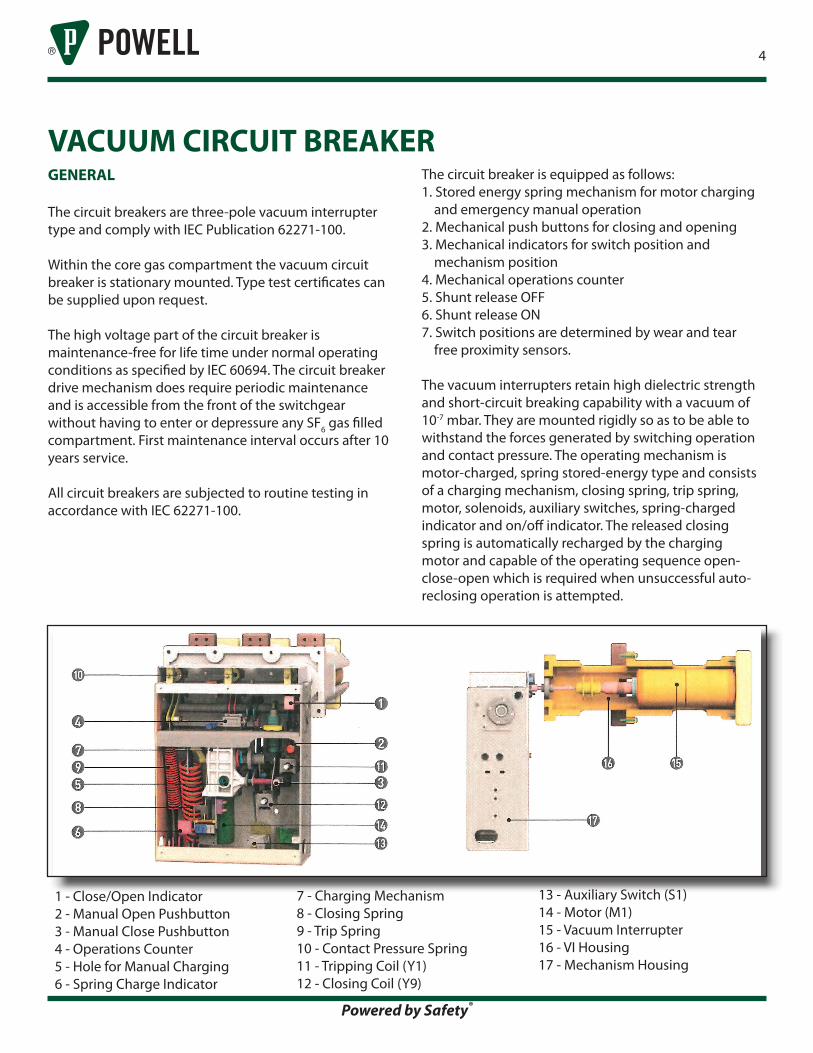
The circuit breaker is equipped as follows: 1. Stored energy spring mechanism for motor charging and emergency manual operation2. Mechanical push buttons for closing and opening3. Mechanical indicators for switch position and mechanism position4. Mechanical operations counter5. Shunt release OFF6. Shunt release ON 7. Switch positions are determined by wear and tear free proximity sensors.
The vacuum interrupters retain high dielectric strength and short-circuit breaking capability with a vacuum of 10-7 mbar. They are mounted rigidly so as to be able to withstand the forces generated by switching operation and contact pressure. The operating mechanism is motor-charged, spring stored-energy type and consists of a charging mechanism, closing spring, trip spring, motor, solenoids, auxiliary switches, spring-charged indicator and on/off indicator. The released closing spring is automatically recharged by the charging motor and capable of the operating sequence open-close-open which is required when unsuccessful auto-reclosing operation is attempted.
1 - Close/Open Indicator 2 - Manual Open Pushbutton 3 - Manual Close Pushbutton 4 - Operations Counter 5 - Hole for Manual Charging 6 - Spring Charge Indicator
7 - Charging Mechanism 8 - Closing Spring 9 - Trip Spring 10 - Contact Pressure Spring 11 - Tripping Coil (Y1) 12 - Closing Coil (Y9)
13 - Auxiliary Switch (S1) 14 - Motor (M1) 15 - Vacuum Interrupter 16 - VI Housing 17 - Mechanism Housing
Powered by Safety®
5
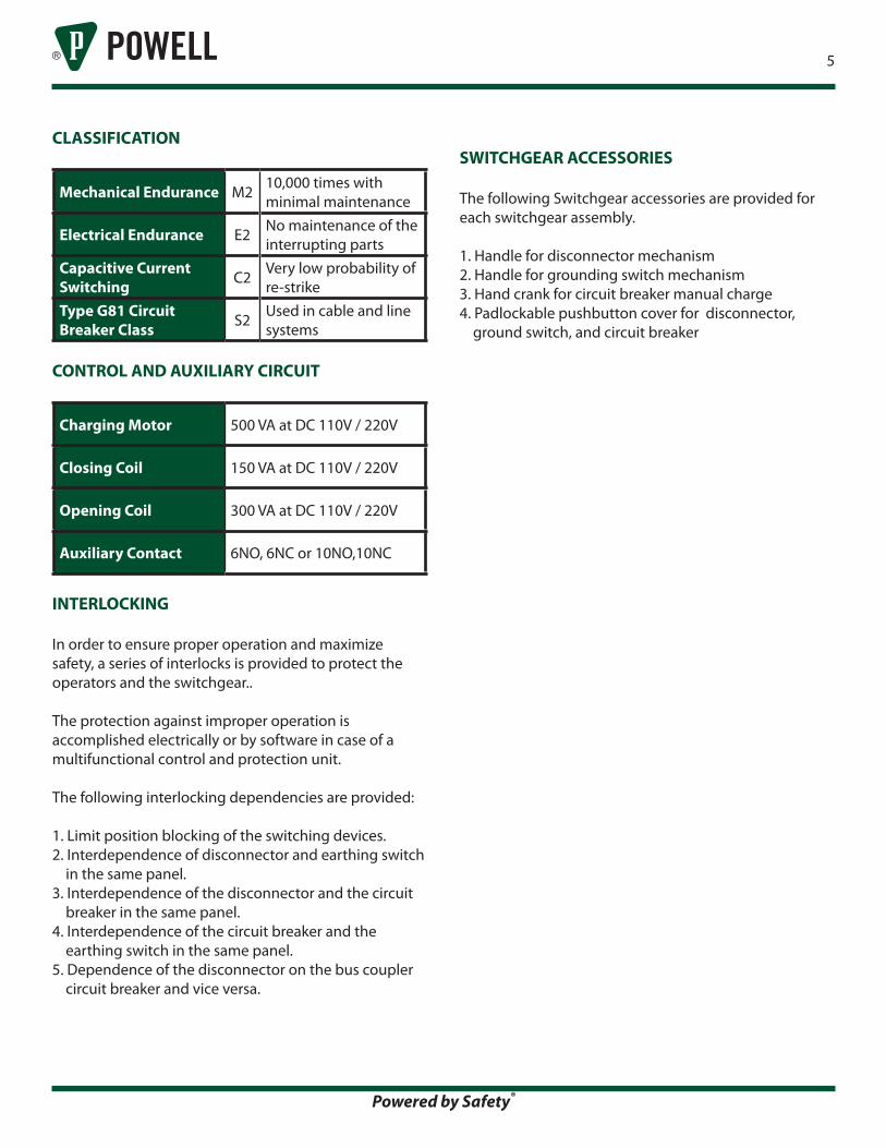
SWITCHGEAR ACCESSORIES
The following Switchgear accessories are provided for each switchgear assembly.
1. Handle for disconnector mechanism2. Handle for grounding switch mechanism3. Hand crank for circuit breaker manual charge4. Padlockable pushbutton cover for disconnector, ground switch, and circuit breaker
CLASSIFICATION
Mechanical Endurance M2 10,000 times with minimal maintenance
Electrical Endurance E2 No maintenance of the interrupting parts
Capacitive Current Switching C2 Very low probability of
re-strikeType G81 Circuit Breaker Class S2 Used in cable and line
systems
CONTROL AND AUXILIARY CIRCUIT
Charging Motor 500 VA at DC 110V / 220V
Closing Coil 150 VA at DC 110V / 220V
Opening Coil 300 VA at DC 110V / 220V
Auxiliary Contact 6NO, 6NC or 10NO,10NC
INTERLOCKING
In order to ensure proper operation and maximize safety, a series of interlocks is provided to protect the operators and the switchgear..
The protection against improper operation is accomplished electrically or by software in case of a multifunctional control and protection unit.
The following interlocking dependencies are provided:
1. Limit position blocking of the switching devices.2. Interdependence of disconnector and earthing switch in the same panel.3. Interdependence of the disconnector and the circuit breaker in the same panel.4. Interdependence of the circuit breaker and the earthing switch in the same panel.5. Dependence of the disconnector on the bus coupler circuit breaker and vice versa.
Powered by Safety®
6
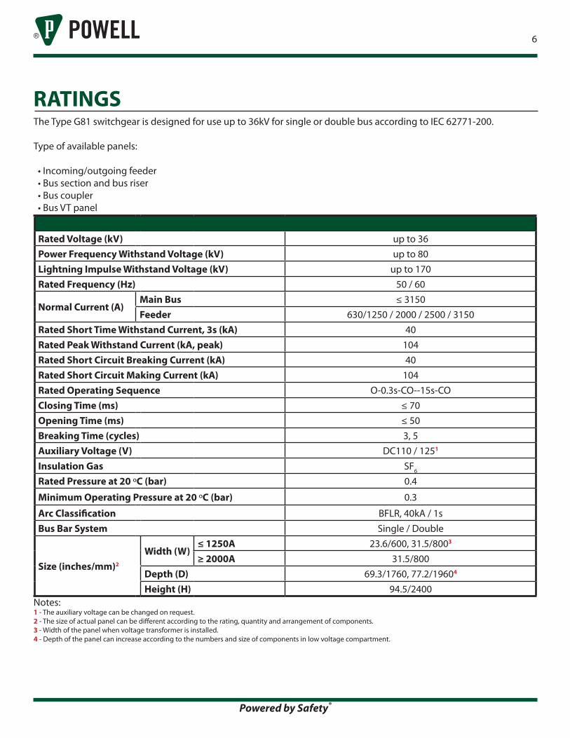
The Type G81 switchgear is designed for use up to 36kV for single or double bus according to IEC 62771-200.
Type of available panels:
• Incoming/outgoing feeder • Bus section and bus riser • Bus coupler • Bus VT panel
Rated Voltage (kV) up to 36Power Frequency Withstand Voltage (kV) up to 80Lightning Impulse Withstand Voltage (kV) up to 170Rated Frequency (Hz) 50 / 60
Normal Current (A)Main Bus ≤ 3150Feeder 630/1250 / 2000 / 2500 / 3150
Rated Short Time Withstand Current, 3s (kA) 40Rated Peak Withstand Current (kA, peak) 104Rated Short Circuit Breaking Current (kA) 40Rated Short Circuit Making Current (kA) 104Rated Operating Sequence O-0.3s-CO--15s-COClosing Time (ms) ≤ 70Opening Time (ms) ≤ 50Breaking Time (cycles) 3, 5Auxiliary Voltage (V) DC110 / 1251
Insulation Gas SF6
Rated Pressure at 20 oC (bar) 0.4
Minimum Operating Pressure at 20 oC (bar) 0.3
Arc Classification BFLR, 40kA / 1sBus Bar System Single / Double
Size (inches/mm)2
Width (W)≤ 1250A 23.6/600, 31.5/8003
≥ 2000A 31.5/800Depth (D) 69.3/1760, 77.2/19604
Height (H) 94.5/2400Notes:1 - The auxiliary voltage can be changed on request.2 - The size of actual panel can be different according to the rating, quantity and arrangement of components.3 - Width of the panel when voltage transformer is installed.4 - Depth of the panel can increase according to the numbers and size of components in low voltage compartment.
RATINGS
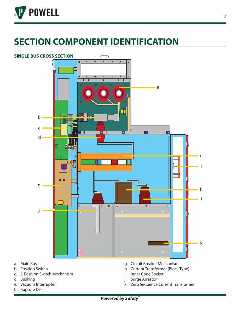
g. Circuit Breaker Mechanismh. Current Transformer (Block Type)i. Inner Cone Socketj. Surge Arrestork. Zero Sequence Current Transformer
SINGLE BUS CROSS SECTION
a. Main Busb. Position Switchc. 3-Position Switch Mechanismd. Bushinge. Vacuum Interrupterf. Rupture Disc
Powered by Safety®
7
SECTION COMPONENT IDENTIFICATION
c
e
f
h
i
k
b
d
g
j
a
Powered by Safety®
8
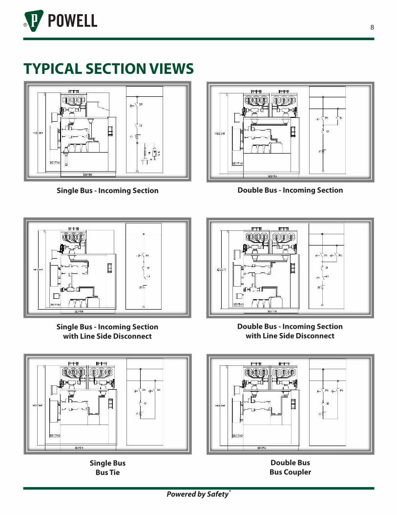
TYPICAL SECTION VIEWS
Single Bus - Incoming Sectionwith Line Side Disconnect
Double Bus - Incoming Sectionwith Line Side Disconnect
Single Bus - Incoming Section Double Bus - Incoming Section
Single Bus Bus Tie
Double BusBus Coupler
9
Powered by Safety®
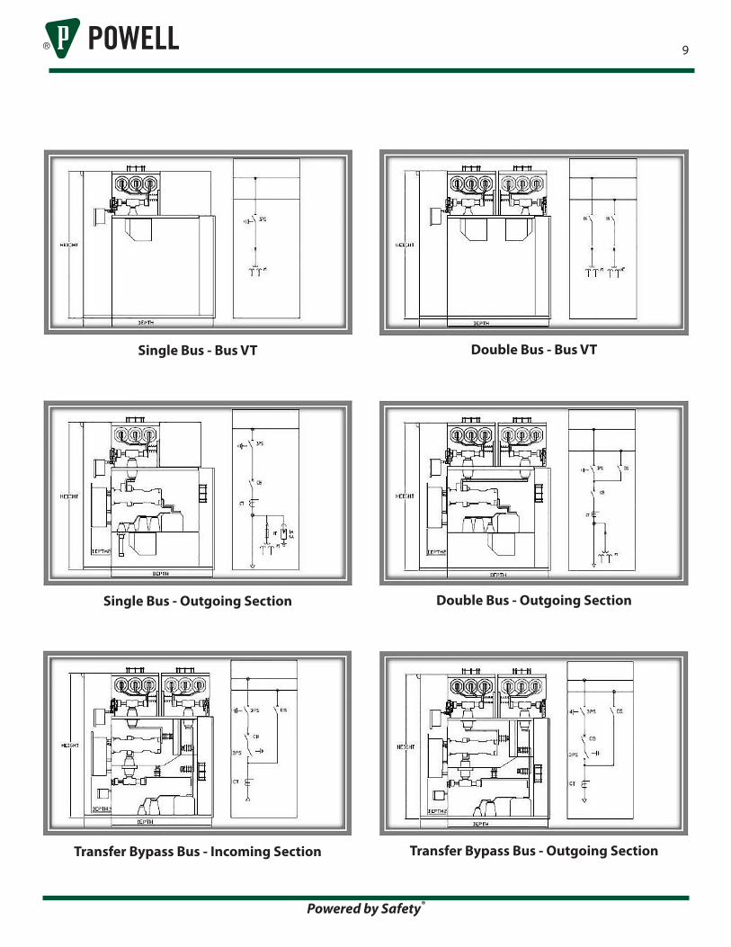
Single Bus - Bus VT Double Bus - Bus VT
Single Bus - Outgoing Section Double Bus - Outgoing Section
Transfer Bypass Bus - Incoming Section Transfer Bypass Bus - Outgoing Section
10
Powered by Safety®
1.0 General1.1 The intent of this specification is to have the manufacturer furnish the equipment and material specified herein complete and operable.
1.2 All standard accessories to the equipment specified shall be supplied even if not specifically mentioned in this specification.
1.3 Material used in the fabrication of the specified equipment shall be new, unused, and of the highest quality available.
2.0 Scope2.1 Work Included
2.1.1 Furnish gas insulated switchgear as detailed in these specifications. Any drawings or data sheets attached to the inquiry shall be considered part of this specification. The equipment shall be complete and operable.
2.1.2 Provide production tests and inspections as detailed in this specification.
2.1.3 To reasonably prevent the possibility of shipping damage, the manufacturer shall prepare the equipment for transportation to the jobsite and monitor the load out of this material.
2.1.4 It shall be the responsibility of the manufacturer to furnish all material, connections, splices, links, special tools, and information required to completely reassemble the switchgear in the field or to facilitate the installation of the switchgear when performed by an electrical contractor.
2.1.5 Guarantee the performance of the switchgear during a reasonable warranty period. This warranty shall, at a minimum, cover the equipment for eighteen (18) months from time of shipment or twelve (12) months from date of energization whichever occurs first.
2.1.6 Supply all drawings, documentation, and information as detailed.
2.2 Work Not Included
2.2.1 Field installation of switchgear, unless otherwise specified.
2.2.2 Connection of incoming cables or bus.
2.2.3 Connection of outgoing branch feeder cables or bus.
2.2.4 Connection of external control cables or wiring.
2.2.5 Supply or installation of the required pressure relief duct system for the safe venting of gases generated during an internal arc fault.
3.0 Codes, Standards and ClassificationsThe applicable codes and standards listed below should be considered as part of this specification. The latest revision in effect at time of inquiry shall apply for all standards referenced.
3.1 Switchgear
3.1.1 IEC 62271-1 High-voltage switchgear and controlgear – Part 1: Common specifications
3.1.2 IEC 62271-200 High-voltage switchgear and controlgear Part 200: AC metal-enclosed switchgear and controlgear for rated voltages above 1kV and up to and including 52kV
3.2 Circuit Breaker
3.2.1 IEC 62271-100 High-voltage switchgear and controlgear Part 100: High-voltage alternating current circuit breaker
3.3 Instrument Transformers
3.3.1 IEC 61869-1 Instrument transformers – Part 1: General requirements
3.3.2 IEC 61869-2 Instrument transformers – Part 2: Additional requirements for current transformers
3.3.3 IEC 61869-3 Instrument transformers-Part 3: Additional requirements for inductive voltage transformers
3.4 Disconnector and Earthing Switch
3.4.1 IEC 62271-102 High-Voltage Switchgear and Controlgear Part 102: Alternating current disconnectors and earthing switches
3.5 Classifications to IEC 62271-200
3.5.1 Partition Class: PM
3.5.2 Loss of Service Continuity Category
3.5.2.1 LSC No classification due to gas-filled compartments
3.5.2.2 LSC2B Cable termination compartments
GUIDE SPECIFICATION
11
Powered by Safety®
3.5.2.3 Classification IAC BLFR 40kA, 1s with pressure relief duct and absorber or discharge into open air
3.6 It shall be the manufacturer’s responsibility to be knowledgeable of these standards and codes.
4.0 Design Criteria4.1 Rated Normal Currents – The rated normal currents of components shall be valid for 40°C.
4.2 Temperature Limits and Environments – Environmental conditions according to VDE and IEC.
4.2.1 Maximum Ambient Temperature 40°C
4.2.2 Minimum Ambient Temperature -5°C (corresponds to minus 5°C indoor class)
4.2.3 Maximum Relative Humidity 90%
4.2.4 The equipment shall be suitable for installation and service at an altitude not exceeding 1000 meters above mean sea level.
5.0 Design Parameters5.1 The equipment shall be designed for a rated maximum voltage of 36kV
5.2 The equipment shall have a nominal system voltage not to exceed 33kV
5.3 The equipment shall have a Rated Power Frequency Withstand Voltage of 80kV
5.4 The equipment shall have a Rated Lightning Impulse Withstand Voltage of 170kV
5.5 The equipment shall be rated for 50/60Hz
5.6 The main power bus bar current rating of 3150A or less.
5.7 The equipment shall have a rated short-time withstand current of 40kA for 3 seconds
5.8 The equipment shall have a rated peak withstand current of 104kA
5.9 The rated operating sequence shall be O-0.3s-CO-3min-CO or O-0.3s-CO-15s-CO
5.10 The insulating gas shall be SF6
5.11 The Degree of Protection for the high-voltage live parts shall be IP65
5.12 The Degree of Protection for the low-voltage compartment shall be IP4X
GUIDE SPECIFICATION (cont.)5.13 The equipment shall be internal arc resistance accessibility Type BFLR and contain pressure relief ducts
6.0 Basic Construction6.1 The switchgear shall be an indoor gas-insulated and metal-enclosed 3-phase design with segregated SF6 insulated compartments for circuit breaker and bus bar systems.
6.2 The switchgear shall be designed to ensure optimum continuity, reliability of supply and safety of operation.
6.3 The high-voltage section shall consist of gas-tight stainless steel tanks built as a sealed pressure system. Each of these gas compartments shall have a filling valve, gas density monitoring pressure sensor and a pressure relief system.
6.4 The bus bar connections between each switchgear section will be non-bolted plug-in type. No gas filling shall be required for onsite assembly.
6.5 The power cables shall enter the bottom and connect by plug-in connectors.
6.6 The cable compartment shall have a pressure relief system leading to the pressure relief duct.
6.7 The switchgear gas compartment leakage rate shall be less than 0.1% per year.
6.8 All high-voltage parts with the exception of cable plugs will be located within SF6 gas filled enclosure.
6.9 Operational safety and insulating properties shall be maintained as long as the SF6 gas is at sea-level atmospheric pressure or greater.
6.10 The switchgear shall contain a passive protection system against internal arc faults in each partitioned compartment in order to maximize operator safety.
6.11 The passive safety section shall ensure that hot gases are guided via pressure relief disks from each SF6 filled compartment. The pressure relief duct ends must be guided to a vented area for personnel safety.
6.12 Temperature-compensated sensors for pressure measurement shall continually monitor each gas compartment.
6.13 The high-voltage compartments shall be maintenance free for the lifetime of the equipment as long as operated within normal service conditions
12
Powered by Safety®
6.14 Compartments
6.14.1 SF6 Gas Compartments, each section shall have:
6.14.1.1 Core module with built in vacuum circuit breaker and current transformers or sensors.
6.14.1.2 Bus bar modules with built in 2 or 3 position switches.
6.14.2 Air Compartments
6.14.2.1 Cable termination compartment including provisions for conventional voltage transformer plug in connection.
6.14.2.2 Low voltage compartment including built in switch drives and secondary control components. It shall be a self-contained unit with an access door and incorporated into the switchgear section. All operating mechanisms will be motorized. Manual emergency operation and mechanical position indicators will be provided.
6.15 Bus Bars
6.15.1 Main bus bars shall be high conductivity copper, uninsulated and silver plated at connection areas.
6.15.2 Ground bus bars shall be uninsulated, unplated copper.
6.16 Control and Secondary Wiring
6.16.1 Control and Secondary Wiring Supplied Integral to the High Voltage, Bus Bar and Circuit Breaker Sealed Tanks
6.16.1.1 DC control wiring shall be Type XHHW, Class 5 flexible conductor, 1.5mm2.
6.16.1.2 AC control wire shall be Type XHHW, Class 5 flexible conductor, 2.5mm2.
6.16.1.3 PT secondary wiring shall be Type XHHW, Class 5 flexible conductor, 4.0mm2.
6.16.1.4 CT secondary wiring shall be Type XHHW, Class 5 flexible conductor, 4.0mm2.
6.16.1.5 Ground wiring shall be Type XHHW, Class 5 flexible conductor, 6.0mm2.
6.16.2 Interface Between Integral and External Secondary Wiring
6.16.2.1 All integral control and secondary wiring shall be terminated on to terminal blocks, shorting type in the case of CT wiring.
GUIDE SPECIFICATION (cont.)6.16.3 Control and Secondary Wiring External to the Sealed Tanks
6.16.3.1 Control wiring shall be SIS type #14 AWG, 41 strand extra flexible, stranded copper or larger.
6.16.3.2 Current transformer secondary wiring shall be SIS type #12 AWG, 65 strand, extra flexible, stranded copper or larger with braided metallic armor covering.
6.16.3.3 Current transformer secondary wiring shall terminate on shorting type terminal blocks.
6.16.3.4 All control wiring shall be UL listed and have a VW-1 flame retardant rating.
6.16.3.5 Exposed wiring shall be suitably protected against contact with sharp edges. Throughout the assembly it must be neatly bundled and secured with nylon wire ties. Where control wiring passes from cubicle to door it must be wrapped with suitable protection so as to prevent damage. Holes cut to allow control wires to pass from cubicle to cubicle will have a grommet for protection.
6.16.3.6 Splicing of control wire is not permitted. Control wiring must be a continuous length from terminal to terminal.
6.16.3.7 Each control wire shall be marked at both terminations to agree with wiring diagrams. Plastic wire markers of either the slip on or heat shrink variety shall be provided.
6.16.3.8 Control wires leaving the cubicle of origin must first terminate on a terminal block. No control wire may leave a cubicle directly from any other device.
6.16.3.9 Control wire tags shall follow ‘Destination Method’ and must match the drawings.
6.16.3.10 Where possible, a minimum of 10% spare terminals shall be provided in each cubicle.
6.17 Meters, Switches, and Relays
6.17.1 Indicating meters shall be three phase large digital display type visible 6 feet away from the front of the lineup and require minimum operator interface.
6.17.2 Control switches shall be rotary cam type with engraved face plates.
6.17.3 Ammeter and voltmeter transfer switches shall have an off position and shall be provided with knurled knob handles.
13
Powered by Safety®
6.17.4 Selector type control switches (Auto-Manual or Hand-Off-Auto) shall have oval handles.
6.17.5 Protective relays shall be switchboard drawout type with removable dust tight viewing covers, front accessible connection plugs, built-in test capability, and mechanical targets that may be externally reset. Other electronic or multi-function relays may be specified for particular applications.
6.17.6 Current and voltage test switches for field monitoring and maintenance shall be provided when specified.
6.17.7 Indicating lights shall be provided as shown on the control schemes. Lamps shall be replaceable from the front of the switchgear without opening the cubicle door.
6.18 Nameplates
6.18.1 Laminated plastic engraved nameplates shall be provided.
6.18.2 Identification nameplates shall be white with black letters, caution nameplates shall be yellow with black letters, and warning nameplates shall be red with white letters.
6.18.3 Each externally visible device or component shall have an identification nameplate. Lettering shall be, at a minimum, 5/32 inches in height.
6.18.4 Each internal device or component shall have an identification marking.
6.18.5 A single large permanent metal nameplate shall identify the sales order No, switchgear ratings and date and place of manufacture.
6.19 Finish
6.19.1 All non stainless steel members shall be cleaned, rinsed and phosphatized prior to finishing.
6.19.2 Coating process shall be an electrostatically applied polyester powder with a final baked on average thickness between 1.5 and 2.0 mils.
6.19.3 Interior instrument compartments shall be White finish for enhanced visibility.
6.19.4 All internal parts shall be painted for corrosion protection, no bare parts allowed.
6.19.5 Standard exterior finish will be light gray.
GUIDE SPECIFICATION (cont.)7.0 Circuit Breakers7.1 The circuit breakers shall be vacuum type and comply with IEC Publication 62271-100.
7.2 The circuit breakers will be stationary mounted and type tested. Test certificates available after receipt of purchase order.
7.3 The high-voltage portion of the circuit breaker will be maintenance free for the lifetime of the equipment when operated within normal service conditions.
7.4 The circuit breaker drive mechanism shall be accessible for maintenance.
7.5 Each circuit breaker shall include:
7.5.1 A stored-energy spring mechanism for motor charging and emergency manual operation.
7.5.2 Mechanical push buttons for closing and opening.
7.5.3 Mechanical indicators for switch position and circuit breaker operating mechanism position.
7.5.4 Circuit breaker operations counter.
7.5.5 Shunt release off.
7.5.6 Shunt release on.
7.5.7 Switch position wear-and-tear free proximity sensors.
8.0 Isolators and Earthing Switches8.1 Isolators and earthing switches shall be motor operated with emergency manual operation capability.
8.2 The earthing position for all three phases must be visible through camera, laptop or monitor display located on the front door.
9.0 Instrument Transformers9.1 Current transformers may be single or multi-ratio type with taps
9.2 Zero-sequence current transformers suitable for outdoor environments may be located below the switchgear assembly.
9.3 Voltage transformers shall be equipped with primary fuses and protected on the secondary side with molded case circuit breakers.
14
Powered by Safety®
GUIDE SPECIFICATION (cont.)10.0 Cable Compartment and Cable Terminations10.1 The primary cable compartment shall contain cable sockets accessible for the connection of the power cables with the related cable termination plugs.
10.2 Power cables and terminations must be done in accordance DIN EN 50180/1 and be inner cone type sizes 2, 3 or 4 with a touch-proof system.
11.0 Interlocking11.1 Limit position blocking of the switching devices.
11.2 Interdependence of the disconnector and earthing switch in the same section.
11.3 Interdependence of the disconnector and circuit breaker in the same section.
11.4 Interdependence of the circuit breaker and the earthing switch in the same section.
11.5 Dependence of the disconnector on the bus coupler circuit breaker and vice versa.
12.0 Accessories12.1 Handle for disconnector mechanism.
12.2 Handle for earthing switch mechanism.
12.3 Hand crank for circuit breaker manual charge.
12.4 Padlockable pushbutton cover for disconnector, earthing switch and circuit breaker operating pushbuttons.
13.0 Inspection and Production Testing13.1 Component bill of material shall be checked for proper quantity, description, and part number.
13.2 Physical dimensions shall be checked against approved drawings.
13.3 Equipment shall be subjected to a primary current injection procedure to determine proper operation of all current sensitive components.
13.4 Equipment shall be subjected to a primary voltage injection procedure to determine proper operation of all voltage sensitive components.
13.5 Complete assembly shall have a low frequency withstand (an AC high potential) test performed to assure insulation system integrity.
13.6 Each gas filled module shall have a gas tank integrity test.
13.7 Manufacturer shall have in place a system of recording, correcting, and verifying resolution of discrepancies discovered during the inspection and testing process.
13.8 Certified production test reports indicating satisfactory completion of all inspection procedures shall be available upon request.
13.9 Upon request the equipment shall be made available for customer inspection prior to shipment.
13.10 Test reports for design tests shall be available upon request.
14.0 Documentation14.1 Drawings
14.1.1 Prior to fabrication the following drawings shall be submitted by the manufacturer for approval.
14.1.1.1 Front elevation view.
14.1.1.2 Base plan including mounting details, cable entry area, and door swing requirements.
14.1.1.3 Cross section view of each different section.
14.1.1.4 Three line diagram.
14.1.1.5 Component bill of material indicating quantity, description, and part number.
14.1.1.6 Control or schematic diagram for each different unit.
14.1.2 Following the return of approval drawings the manufacturer shall prepare and submit wiring diagrams indicating physical location of secondary control components and the appropriate wiring connections. Each control wire will be labeled. Copies of these drawings shall be submitted to the customer, upon completion, for record.
14.1.3 After the return of approval drawings or after any change made to previously approved drawings, the manufacturer shall submit a record copy of any and all drawings that contained revisions.
14.1.4 After completion of the inspection and testing procedures the manufacturer shall submit a complete set of “as built” drawings. These drawings shall function
15
Powered by Safety®
GUIDE SPECIFICATION (cont.)as a record of the final construction of the equipment at the time it left the factory.
14.1.5 Drawings may be provided in any of the following forms as requested by the customer:
14.1.5.1 Full size plotted reproducible drawings size as required. “D size” measuring approximately 34” x 22”, “C size” measuring approximately 22” x 17”, “B size” measuring approximately 17” x 11”, or “A size” measuring approximately 11” x 8½”.
14.1.5.2 Digital files in the latest version of Autodesk AutoCAD.
14.1.5.3 Digital file format may be dwf, pdf, dgn, or dwg as specified.
14.1.6 Each drawing prepared by manufacturer shall show, at a minimum, the name, jobsite location, purchase order or contract number, and equipment identification number in addition to any information required by manufacturer.
14.2 Operating and Maintenance Manuals
14.2.1 At time of shipment the manufacturer shall provide a copy of the operating and maintenance instructions for all major components contained in the switchgear assembly.
14.2.2 Manuals shall contain a table of contents to allow for easy reference.
14.2.3 Operating and maintenance manual will be provided as pdf files on a CD for easy reference.
14.3 Spare Parts List
14.3.1 Upon completion of the engineering phase, a quotation for one (1) year’s recommended spare parts shall be submitted.

Contact UsPowell Electrical Systems, Inc.7232 Airport Blvd.Houston, Texas 77061713.790.1700
Powell Canada Inc.53032 Range Road 263AAcheson, Alberta T7X 5A5780.948.3300
Powell (UK) Ltd.Ripley RoadBradford, West Yorkshire BD4 7EH+44.(0).1274.734221
Powered by Safety®
06/2015 v4Publication No. 04162
powellind.com
©2015 Powell Industries, Inc.. all rights reserved.


