Cisco Confidential © 2012 Cisco and/or its affiliates. All rights reserved. 1
Precise Time Transfer in DOCSIS Cable Access Networks Laurent MONTINI Technical Leader – R&AD
ITSF November 2012
© 2012 Cisco and/or its affiliates. All rights reserved. Cisco Confidential 2
!
Internet
Cable Operator Network
Video and data
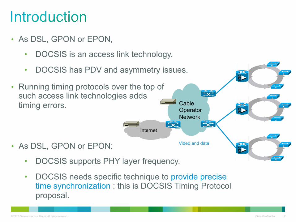
• As DSL, GPON or EPON,
• DOCSIS is an access link technology.
• DOCSIS has PDV and asymmetry issues.
• As DSL, GPON or EPON:
• DOCSIS supports PHY layer frequency.
• DOCSIS needs specific technique to provide precise time synchronization : this is DOCSIS Timing Protocol proposal.
• Running timing protocols over the top of such access link technologies adds timing errors.

© 2012 Cisco and/or its affiliates. All rights reserved. Cisco Confidential 3
• DOCSIS Overview
• Some DOCSIS Transmission Fundamentals Boot-up / Initialization Ranging process
• DOCSIS Timing Protocol DTP System True Ranging Offset
• DTP Use Cases
© 2012 Cisco and/or its affiliates. All rights reserved. Cisco Confidential 4
!
HFC
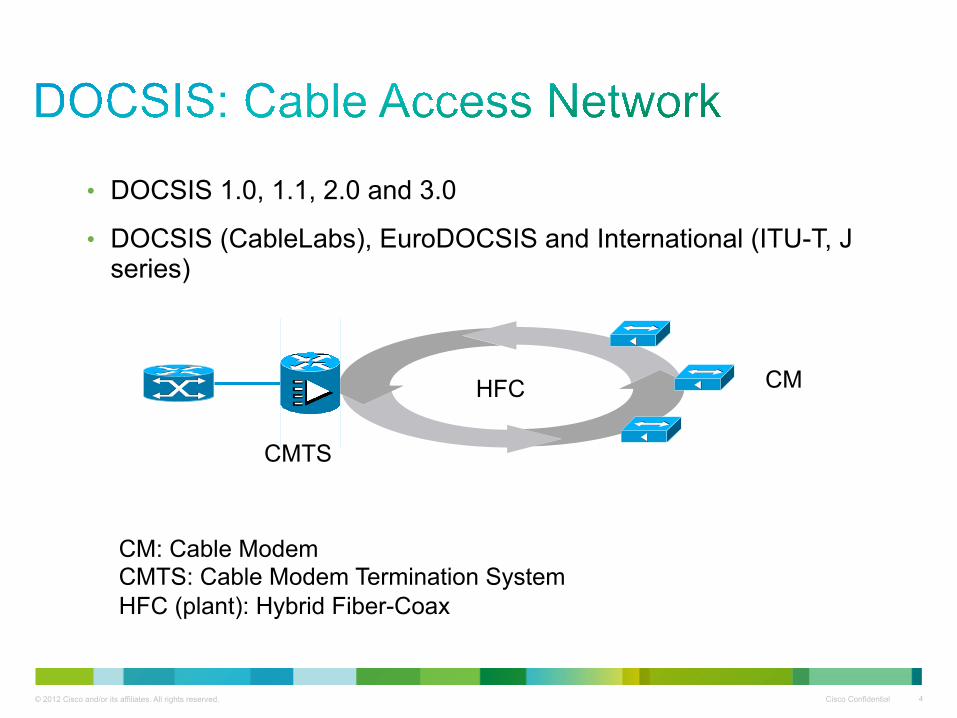
CM: Cable Modem CMTS: Cable Modem Termination System HFC (plant): Hybrid Fiber-Coax
CM
CMTS
• DOCSIS 1.0, 1.1, 2.0 and 3.0
• DOCSIS (CableLabs), EuroDOCSIS and International (ITU-T, J series)

© 2012 Cisco and/or its affiliates. All rights reserved. Cisco Confidential 5
!
HFC
CM
CMTS
HFC RF Plant: up to 160 km optical fiber, 300 meters of coaxial cable with use of fiber optic, RF distribution amplifiers and RF passive devices
RX (Upstream)
TX (Downstream)
CM
CMTS
CM
CM
© 2012 Cisco and/or its affiliates. All rights reserved. Cisco Confidential 6
Frequency
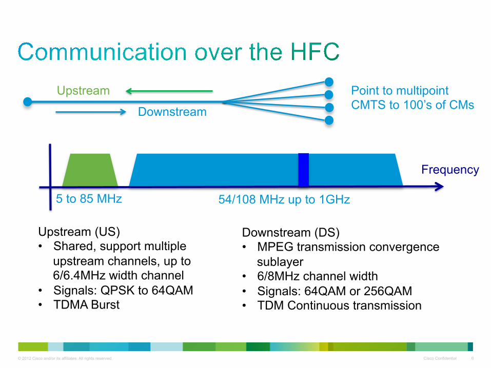
Downstream (DS) • MPEG transmission convergence
sublayer • 6/8MHz channel width • Signals: 64QAM or 256QAM • TDM Continuous transmission
Upstream (US) • Shared, support multiple
upstream channels, up to 6/6.4MHz width channel
• Signals: QPSK to 64QAM • TDMA Burst
Upstream
Downstream
5 to 85 MHz 54/108 MHz up to 1GHz
Point to multipoint CMTS to 100’s of CMs

© 2012 Cisco and/or its affiliates. All rights reserved. Cisco Confidential 7
• All simultaneous users contend for the US and DS access.
• The CMTS transmits data to the cable modems on a first come, first served basis.
• CMs must time-shared upstream channels. Request and Grant reservation scheme
• Only one modem can be active in the US at any given instant in time.
• The DOCSIS path delay is inherently asymmetrical and can contain a moderate to high amount of jitter.

© 2012 Cisco and/or its affiliates. All rights reserved. Cisco Confidential 8
• MAC management messages are Ethernet frames with TLV payload.
Ex: SYNC, MAP, Ranging Request/Response TLVs
• MAP (Media Access Protocol) assigns upstream transmit opportunities.
• The Request-and-Grant cycle between the CMTS and the CMs use MAP messages.
• This back-and-forth communication produces latency.
• The CM might miss a MAP, which creates jitter for over the top timing protocol.
© 2012 Cisco and/or its affiliates. All rights reserved. Cisco Confidential 9
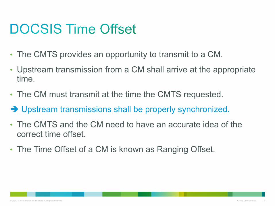
• The CMTS provides an opportunity to transmit to a CM.
• Upstream transmission from a CM shall arrive at the appropriate time.
• The CM must transmit at the time the CMTS requested.
Upstream transmissions shall be properly synchronized.
• The CMTS and the CM need to have an accurate idea of the correct time offset.
• The Time Offset of a CM is known as Ranging Offset.

© 2012 Cisco and/or its affiliates. All rights reserved. Cisco Confidential 10
• Ranging Offset (time offset) is a value indicating the round trip delay between a CMTS and a connected CM.
• It is determined by four major factors: Physical distance (HFC round trip delay) Downstream modulation scheme and interleave depth Upstream modulation scheme and channel width Model of CM and firmware
• Initial Ranging offset happens at boot-up and shall be performed it again after any link interruption.
• A Station Maintenance Ranging (every 30 sec max) is performed after the channel is successfully established.
CMTS will analyze and adjust the time offset if necessary.
© 2012 Cisco and/or its affiliates. All rights reserved. Cisco Confidential 11
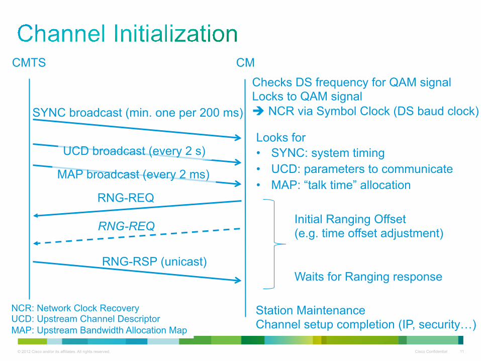
CM CMTS
SYNC broadcast (min. one per 200 ms)
RNG-REQ Initial Ranging Offset (e.g. time offset adjustment) Waits for Ranging response
UCD broadcast (every 2 s)
MAP broadcast (every 2 ms)
Station Maintenance Channel setup completion (IP, security…)
NCR: Network Clock Recovery UCD: Upstream Channel Descriptor MAP: Upstream Bandwidth Allocation Map
RNG-REQ
RNG-RSP (unicast)
Checks DS frequency for QAM signal Locks to QAM signal NCR via Symbol Clock (DS baud clock)
Looks for • SYNC: system timing • UCD: parameters to communicate • MAP: “talk time” allocation
© 2012 Cisco and/or its affiliates. All rights reserved. Cisco Confidential 12
0 1 2 3 5 4 7 6 8 9 11
10
13
12
15
14
16
17
18
19
20
21
22
24
23
25
? ? ?
CMTS
CM
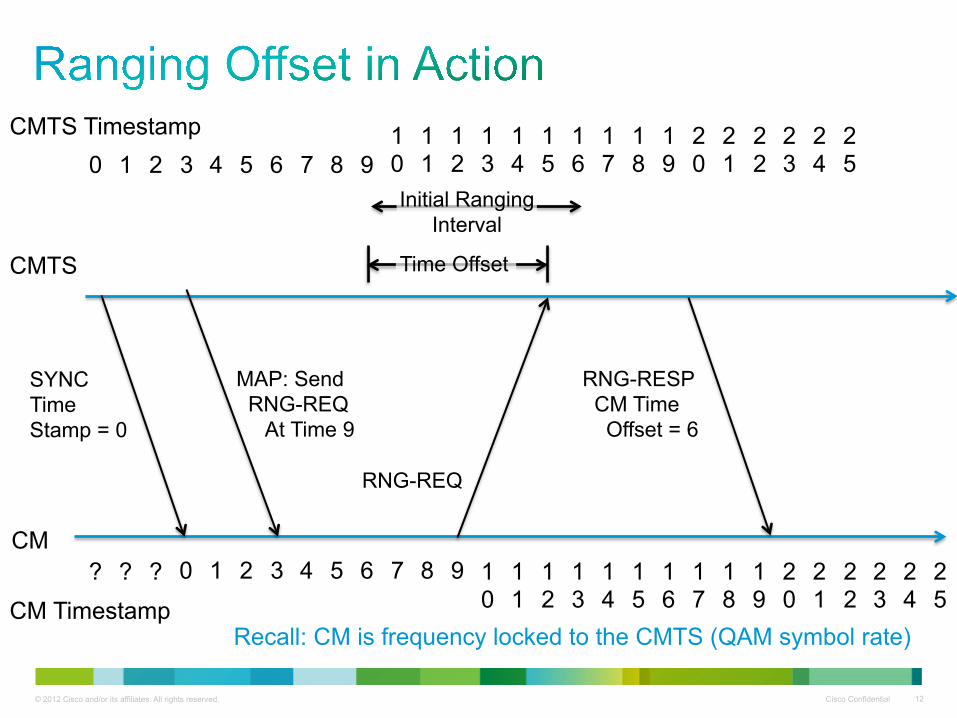
CMTS Timestamp
CM Timestamp
SYNC Time Stamp = 0
0 1 2 3 5 4 7 6 8 9 11
10
13
12
15
14
16
17
18
19
20
21
22
24
23
25
MAP: Send RNG-REQ At Time 9
Initial Ranging Interval
Time Offset
RNG-REQ
RNG-RESP CM Time Offset = 6
Recall: CM is frequency locked to the CMTS (QAM symbol rate)

© 2012 Cisco and/or its affiliates. All rights reserved. Cisco Confidential 13
31
30
33
32
35
34
36
37
38
39
26
27
22
24
23
25
CMTS
CM
CMTS Timestamp
CM Timestamp
MAP: Transmit At Time 49
TX data sent at time 43 = 49 - 6
28
29
41
40
43
42
45
44
46
47
48
49
31
30
33
32
35
34
36
37
38
39
26
27
22
24
23
25
28
29
41
40
43
42
45
44
46
47
19
20
21
Time Offset = 6
© 2012 Cisco and/or its affiliates. All rights reserved. Cisco Confidential 14
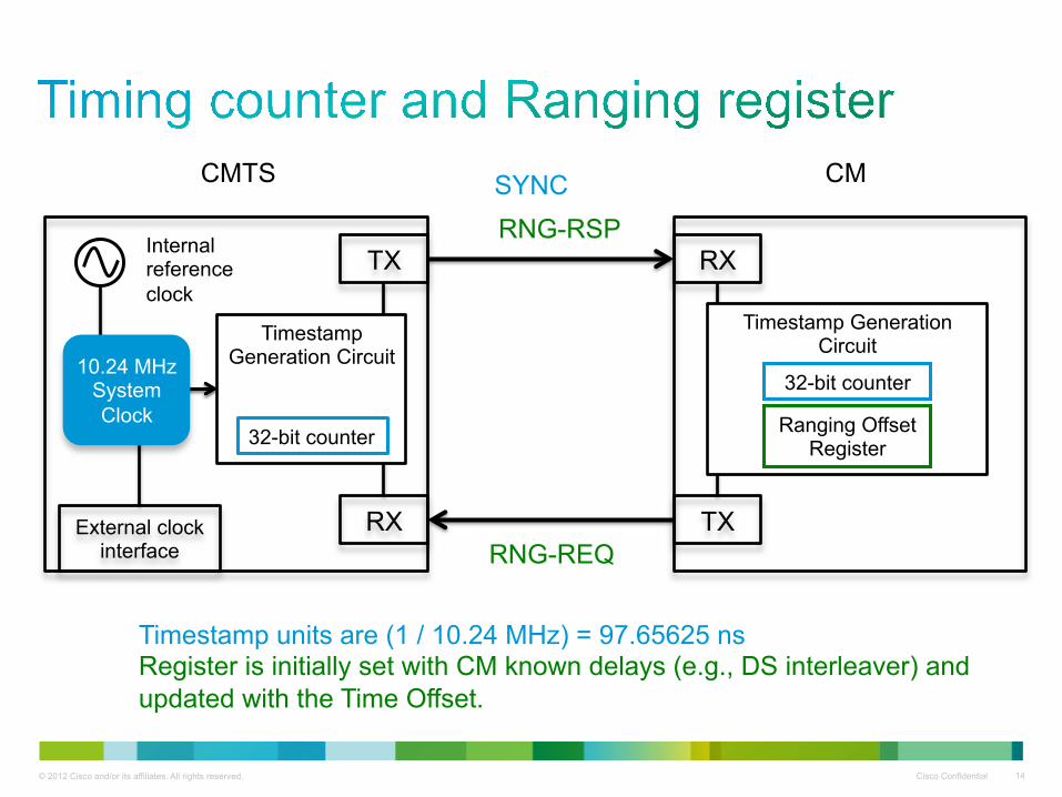
TX
RX
Timestamp Generation Circuit
32-bit counter
10.24 MHz System Clock
External clock interface
Internal reference clock
TX
RX
Timestamp Generation Circuit
32-bit counter
SYNC
Ranging Offset Register
RNG-RSP
RNG-REQ
CM CMTS
Timestamp units are (1 / 10.24 MHz) = 97.65625 ns Register is initially set with CM known delays (e.g., DS interleaver) and updated with the Time Offset.

© 2012 Cisco and/or its affiliates. All rights reserved. Cisco Confidential 15
!
M-CMTS: Modular Cable Modem Termination System E-QAM: Edge QAM DEPI: Downstream External PHY Interface DTI: DOCSIS Timing Interface
HFC
CM
DTI Server Downstream Modulation (E-QAM modulator)
DEPI
DTI
M-CMTS
M-CMTS Core with Upstream Receiver
© 2012 Cisco and/or its affiliates. All rights reserved. Cisco Confidential 16
• DTP is a series of extensions proposed for precise time synchronization.
• DTP synchronizes the DTP server/CMTS and DTP clients (CM). Propagation delay from DTP server to DTP clients is measured. Asymmetry is compensated for.
• The CM (DTP client) has a newly defined “True Ranging Offset”.
• In essence, the total round trip delay is equal to the true ranging offset of the DTP client.
© 2012 Cisco and/or its affiliates. All rights reserved. Cisco Confidential 17
• The TRO is defined as: The difference between the time the first bit of a packet is transmitted in the upstream from the DTP client (in terms of the DOCSIS timestamp), And the time the first bit of the packet is expected to arrive at the DTP server/CMTS.
• TRO is measured in (new) hardware at the DTP client. Need also new hardware at the CMTS DOCSIS interface.
• Since the measurement is done when an upstream packet is transmitted, all upstream scheduling jitter is eliminated.
• TRO is a value that can be measured consistently across different DTP client implementations.
© 2012 Cisco and/or its affiliates. All rights reserved. Cisco Confidential 18
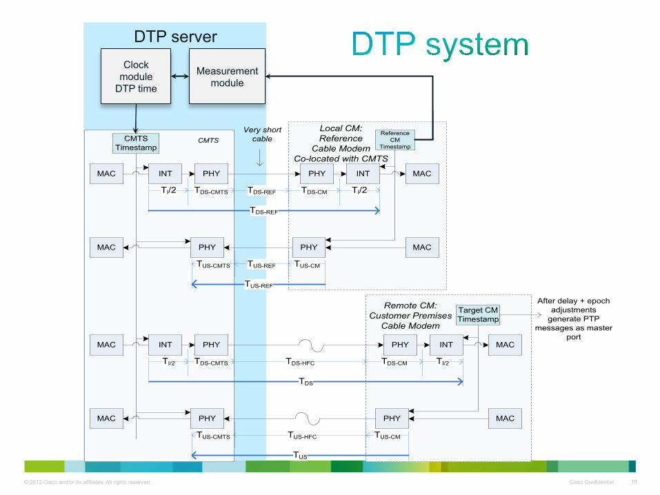
DTP Server
MAC INT PHY
TDS-CMTSTI/2
PHY INT
TI/2TDS-CM
MAC
CMTS Timestamp
TDS-HFC
TDS
MAC PHY
TUS-CMTS
PHY
TUS-CM
MAC
TUS-HFC
TUS
Target CMTimestamp
Remote CM: Customer Premises
Cable Modem
MAC INT PHY
TDS-CMTSTI/2
PHY INT
TI/2TDS-CM
MAC
TDS-REF
TDS-REF
MAC PHY
TUS-CMTS
PHY
TUS-CM
MAC
TUS-REF
TUS-REF
Reference CM
Timestamp
Local CM:Reference
Cable Modem Co-located with CMTS
CMTS
After delay + epoch adjustments
generate PTP messages as master
port
DTI Server
PTP
PTP SlaveDTI TimeCompare time to compensate for asymmetry between
upstream and downstream paths between CMTS and CM
Very short cable
DTP server Clock
module DTP time
Measurement module
© 2012 Cisco and/or its affiliates. All rights reserved. Cisco Confidential 19
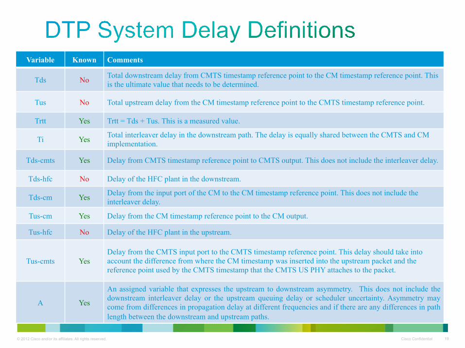
Variable Known Comments
Tds No Total downstream delay from CMTS timestamp reference point to the CM timestamp reference point. This is the ultimate value that needs to be determined.
Tus No Total upstream delay from the CM timestamp reference point to the CMTS timestamp reference point.
Trtt Yes Trtt = Tds + Tus. This is a measured value.
Ti Yes Total interleaver delay in the downstream path. The delay is equally shared between the CMTS and CM implementation.
Tds-cmts Yes Delay from CMTS timestamp reference point to CMTS output. This does not include the interleaver delay.
Tds-hfc No Delay of the HFC plant in the downstream.
Tds-cm Yes Delay from the input port of the CM to the CM timestamp reference point. This does not include the interleaver delay.
Tus-cm Yes Delay from the CM timestamp reference point to the CM output.
Tus-hfc No Delay of the HFC plant in the upstream.
Tus-cmts Yes Delay from the CMTS input port to the CMTS timestamp reference point. This delay should take into account the difference from where the CM timestamp was inserted into the upstream packet and the reference point used by the CMTS timestamp that the CMTS US PHY attaches to the packet.
A Yes
An assigned variable that expresses the upstream to downstream asymmetry. This does not include the downstream interleaver delay or the upstream queuing delay or scheduler uncertainty. Asymmetry may come from differences in propagation delay at different frequencies and if there are any differences in path length between the downstream and upstream paths.
© 2012 Cisco and/or its affiliates. All rights reserved. Cisco Confidential 20
500
500
500
500
750
750
800
SYNC
MAP (Tx=7000)
RNG REQ
2000
2000
4000
7000
4000
4300
5200
5800
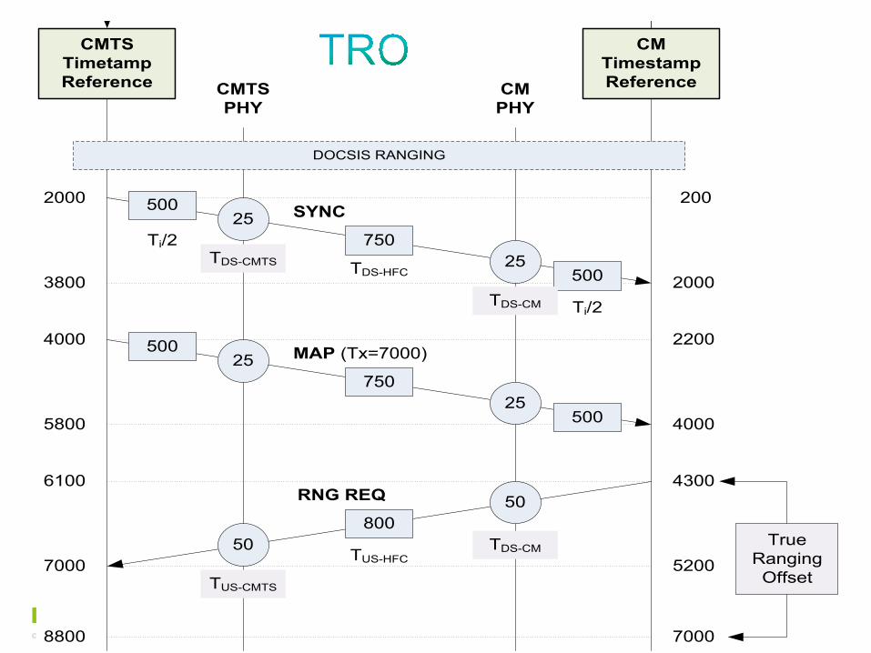
Where: - All values are in arbitrary time units for sake of example.- Upstream HFC delay is set to slightly more than downstream HFC delay- DOCSIS ranging process determines internal offset for upstream tx time.
Thus:Round Trip Delay (calculated) = 500 + 25 + 750 + 25 + 500 + 50 + 800 + 50 = 2700True Ranging Offset (measured) = 7000 – 4300 = 2700
Formula Results:Actual Offset Needed: PTP Offset = 500 + 25 + 750 + 25 + 500 = 1800Formula (1) approximation: PTP Offset = (2700 – 1000) / 2 + 1000 = 1850Formula (9) with Tus-off = 0: PTP Offset = 1050 +(2700 – 1150) / 2 = 1825Formula (9) with Tus-off = 50: PTP Offset = 1050 +(2700 – 1150 - 50) / 2 = 1800
200
DOCSIS RANGING
7000
TrueRangingOffset
PTP Timestamp
CMTS Timetamp Reference CMTS
PHYCMPHY
CMTimestampReference
8800
Sync & Conversion
PTP Timestamp
25
25
50
50
Sync & Conversion
3800
2200
6100
25
25
Ti/2TDS-CMTS
Ti/2TDS-CM
TDS-HFC
TDS-CMTUS-HFC
TUS-CMTS
© 2012 Cisco and/or its affiliates. All rights reserved. Cisco Confidential 21
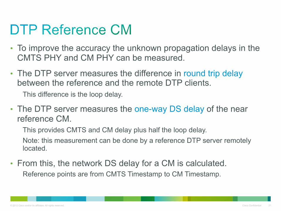
• To improve the accuracy the unknown propagation delays in the CMTS PHY and CM PHY can be measured.
• The DTP server measures the difference in round trip delay between the reference and the remote DTP clients.
This difference is the loop delay.
• The DTP server measures the one-way DS delay of the near reference CM.
This provides CMTS and CM delay plus half the loop delay. Note: this measurement can be done by a reference DTP server remotely located.
• From this, the network DS delay for a CM is calculated. Reference points are from CMTS Timestamp to CM Timestamp.

© 2012 Cisco and/or its affiliates. All rights reserved. Cisco Confidential 22
• DTP clock domain timing input: External timing source (e.g., GNSS) embedded or via input interface (e.g. DTI) SyncE PTP (or NTP)
• CM Timing Output: SyncE PTP or NTP
Timing interface(s)
DTP Server
CMTS CM
DTP Server is the time source of the DTP system clock. • External DTI server • DTI Server integrated into CMTS • SyncE / PTP slave port in CMTS
Network
Optional Reference CM Clock
Reference
© 2012 Cisco and/or its affiliates. All rights reserved. Cisco Confidential 23
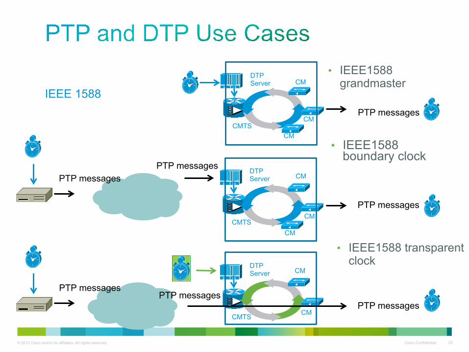
• IEEE1588 grandmaster
DTP Server
CM CMTS
CM
CM
DTP Server
CM CMTS
CM
CM
• IEEE1588 boundary clock
PTP messages
PTP messages PTP messages
DTP Server
CMTS CM
CM
PTP messages PTP messages
• IEEE1588 transparent clock
PTP messages
PTP messages
IEEE 1588

© 2012 Cisco and/or its affiliates. All rights reserved. Cisco Confidential 24
# Description 1 Timing source at DTP Server/CMTS location
1a CM acts as IEEE1588 grandmaster (or NTP server)
1b CM acts as IEEE1588 grandmaster faking the DTP Server
1c DTP Server acts as IEEE1588 grandmaster (or NTP Stratum 1 server) CM acts as IEEE1588 boundary clock (or NTP stratum server)
2 Timing source and IEEE1588 grandmaster (or NTP server) is upwards the DTP Server location
2a DTP Server fakes the IEEE1588 grandmaster (or NTP Stratum 1 server)
2b DTP Server/CMTS/CM acts as a distributed IEEE1588 boundary clock (or NTP servers)
2c DTP Server/CMTS and CM are virtual IEEE1588 boundary clocks (or NTP servers)
2d CMTS and CM are distributed or virtual IEEE1588 boundary clocks (or NTP servers); DTP Server is removed from timing communication path
3 CMTS/CM acts as a distributed IEEE1588 transparent clock
© 2012 Cisco and/or its affiliates. All rights reserved. Cisco Confidential 25
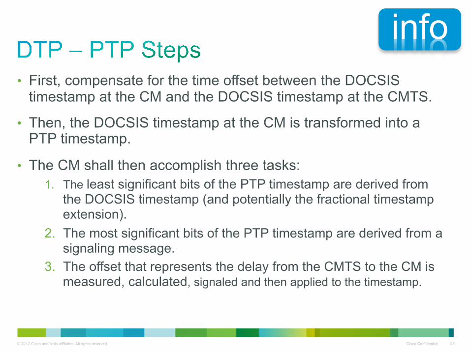
• First, compensate for the time offset between the DOCSIS timestamp at the CM and the DOCSIS timestamp at the CMTS.
• Then, the DOCSIS timestamp at the CM is transformed into a PTP timestamp.
• The CM shall then accomplish three tasks: 1. The least significant bits of the PTP timestamp are derived from
the DOCSIS timestamp (and potentially the fractional timestamp extension).
2. The most significant bits of the PTP timestamp are derived from a signaling message.
3. The offset that represents the delay from the CMTS to the CM is measured, calculated, signaled and then applied to the timestamp.
info

© 2012 Cisco and/or its affiliates. All rights reserved. Cisco Confidential 26
• DOCSIC asymmetry and jitter introduce error into any timing protocol that might traverse the DOCSIS network.
• DTP mitigates these two factors by modifying the DOCSIS hardware design and deriving timing information directly from the DOCSIS system at the CM.
• DTP leverages and improves DOCSIS system timing, coupling: Frequency: CM Ethernet clock to the DOCSIS downstream baud clock. Time: CM PTP timestamp to the DOCSIS SYNC timestamp. Time offset and asymmetry: measurement, signaling and ranging.
• Support of SyncE, NTP or/and PTP is implementation dependent.

Thank you.


