
PRESSURE FITTINGSPE 100
Short and long fittings for butt welding and electrofusion


1
General foreword: Application of FIP PE pressure fittings
General foreword
General foreword:Application of FIP PE pressure fittings
FIP PE pressure fittings have been used for years in areas of application
where the pipe system has to meet high standards of durability and relia-
bility. These standards are met by combining the excellent material pro-
perties of PE with homogeneous welded joints.
Water treatment installations Their high impact resistance, wide temperature range and outstanding
chemical resistance make PE pressure pipe systems extremely suitable for
the transport of waste water in water treatment installations. As well as
standard fittings for this application, special fabricated fittings, dismantling
joints and wall ducts are available.
Waste water transportGood flexibility, high impact resistance and wide temperature range
make PE pressure pipe systems extremely suitable for the use in pressure
sewage systems such as public sewers, culverts etc. As well as standard
fittings for this area of application, long radius bends made from pipe,
special electrofusion couplers and customer made inspection chambers
and pump pits are available.
Swimming pool constructionsThe already mentioned properties high impact resistance, wide tempera-
ture range and excellent chemical resistance make PE pressure pipe sys-
tems extremely suitable for application in high quality swimming pool
installations. As well as standard fittings for this application, special fabri-
cated fittings, dismantling joints and wall ducts are available.
Industrial process pipe systemsThe outstanding chemical resistance and wide temperature range make
PE pressure pipe systems extremely suitable for installations in e.g. the
process and food process industry. As well as standard fittings for this
area of application, screw couplings and union ends for connection to
valves and pumps are available.
Transport of solids The high wear resistance, good flexibility and the smooth internal wall
make PE pressure systems extremely suitable for the transportation of
solids in amongst others sand & gravel dredging and mining industry. As
well as standard fittings for this area of application, long radius bends
made from pipe, flanged joints and electrofusion sockets are available.

General foreword: Application of FIP PE pressure fittings
2 General foreword

3
Table of contentsAbriged table of contents
Table of contents
1 "Plastic" material.............................................................................................................112 Material properties of PE..................................................................................................193 Planning criteria...............................................................................................................314 Standards ........................................................................................................................335 Installation.......................................................................................................................376 Planning and construction guidelines and stress types......................................................417 Basic calculations .............................................................................................................518 Jointing ...........................................................................................................................65
Short fittings for butt-welding ............................................................................................71Long fittings for butt-welding and electrofusion ...............................................................103Fittings made from pipe....................................................................................................118Backing rings and gaskets.................................................................................................184GOEMA pipe clips.............................................................................................................197
9 Welding polyolefins .......................................................................................................20310 Quality ........................................................................................................................215
Appendix A to E ...............................................................................................................219
Specification Manual PE pressure fittings
Catalogue
Jointing techniques
Appendices

Total table of contents
4
Table of contents
Table of contents
General forewordGeneral foreword: Application of FIP PE pressure fittings ..................................................... 1
Table of contentsAbriged table of contents .................................................................................................... 3Total table of contents......................................................................................................... 4
ForewordForeword Specification Manual.......................................................................................... 10
1 "Plastic" material1.1 Classification of plastics ............................................................................................... 111.2 Thermosets and elastomers.......................................................................................... 111.3 Thermoplastics............................................................................................................. 111.4 Characteristics of amorphous and semi-crystalline thermoplastics ................................ 121.5 Plastic processing machines ......................................................................................... 121.6 Mechanical properties.................................................................................................. 131.7 Thermal properties....................................................................................................... 151.8 Chemical properties..................................................................................................... 161.9 Processing characteristic: Melt index ............................................................................ 161.10 Physics of plastics....................................................................................................... 161.11 Chapter summary ...................................................................................................... 18
2 Material properties of PE2.1 General material properties of polyethylene (PE) .......................................................... 192.2 Properties of PE100 ..................................................................................................... 192.3 Chemical resistance ..................................................................................................... 212.4 Health assessment of PE .............................................................................................. 302.5 Chapter summary ........................................................................................................ 30
3 Planning criteria3.1 Selection criteria for PE pipe systems............................................................................ 313.2 User instructions .......................................................................................................... 313.3 Checklist for pipe and equipment contractors .............................................................. 32
4 Standards4.1 General ....................................................................................................................... 334.2 Minimum required strength (MRS) ............................................................................... 334.3 Pipe series number (ISO-S) ........................................................................................... 334.4 Maximum operating pressure (MOP)............................................................................ 344.5 Standard dimension ratio (SDR).................................................................................... 344.6 The polyethylene (PE) mark .......................................................................................... 344.7 Load capacity of welded PE100 pipe and fittings.......................................................... 354.8 Wall thicknesses and acceptable internal pressure load capacity for PE100 pipes.......... 354.9 Chapter summary ........................................................................................................ 36
Specification Manual PE pressure fittings

5
Table of contentsTotal table of contents
Table of contents
5 Installation5.1 Pre-requisites ................................................................................................................375.2 General ........................................................................................................................375.3 Classification criteria .....................................................................................................375.4 Influence of operating conditions..................................................................................375.5 Structural analysis .........................................................................................................37
6 Planning and construction guidelines and stress types6.1 Internal and external pressure loads ..............................................................................416.2 Stress due to pipe deflection.........................................................................................416.4 Loads on buried pipe systems .......................................................................................426.5 Causes of length change ..............................................................................................446.6 Compensation for length changes ................................................................................446.7 Brackets .......................................................................................................................456.8 Construction and installation of buried pipe systems.....................................................466.9 Principles of constructing and installing concrete-encased pipe systems ........................486.10 Chapter summary .......................................................................................................49
7 Basic calculations7.1 Factors influencing pipe system design..........................................................................517.2 Calculating pipe parameters .........................................................................................51
8 Jointing8.1 General ........................................................................................................................658.2 Detachable connections................................................................................................658.3 Non-detachable connections.........................................................................................678.4 Chapter summary .........................................................................................................68
ForewordForeword catalogue............................................................................................................70
PE100 pressure fittings
Short fittings for butt-weldingStub flanges .......................................................................................................................71Tees ...................................................................................................................................77Bends .................................................................................................................................84Reducers ............................................................................................................................86End caps.............................................................................................................................94Unions................................................................................................................................96Adaptors ..........................................................................................................................102
Catalogue

Total table of contents
6
Table of contents
Table of contents
Long fittings for butt-welding and electrofusionStub flanges .................................................................................................................... 103Tees................................................................................................................................. 105Elbows............................................................................................................................. 109Bends .............................................................................................................................. 112Reducers.......................................................................................................................... 113End caps.......................................................................................................................... 116
Fittings made from pipeTees welded .................................................................................................................... 118Tees welded with reduced branch.................................................................................... 123Tees extrusion welded with reduced branch..................................................................... 129Tees reduced machined - pressure class ........................................................................... 137Bends seamless formed.................................................................................................... 145Bends welded .................................................................................................................. 182
Backing rings and gasketsProfile backing rings PP with ductile iron core .................................................................. 184Backing rings PP with ductile iron core............................................................................. 186Profile backing rings ductile iron and coated .................................................................... 188Backing rings GRP............................................................................................................ 190Flange connections .......................................................................................................... 191Blind flanges.................................................................................................................... 193Gaskets ........................................................................................................................... 194Profile gaskets ................................................................................................................. 196
GOEMA pipe clipsPipe clips complete .......................................................................................................... 197Pipe clips components ..................................................................................................... 199
9 Welding polyolefins9.1 General ..................................................................................................................... 2039.2 Welding procedures................................................................................................... 2039.3 Test procedures for evaluating welds ......................................................................... 2109.4 Chapter summary ...................................................................................................... 213
10 Quality10.1 Production quality.................................................................................................... 21510.2 Quality inspection during work-site assembly ........................................................... 21510.3 Leak test prior to initial use ...................................................................................... 21510.4 Chapter summary .................................................................................................... 216
GOEMA pipe clips
Jointing techniques

7
Table of contentsTotal table of contents
Table of contents
Appendix AGeneral Diagrams.............................................................................................................219
Appendix BDiagrams: Pressure pipe systems .......................................................................................237
Appendix CExplanation of the applied formulas and abbreviations......................................................249
Appendix DConversion tables .............................................................................................................253
Appendix EStandards and guidelines ..................................................................................................255
IndexAlphabetical index ............................................................................................................259Index of article numbers ...................................................................................................263
Appendices

Total table of contents
8
Table of contents
Table of contents

SPECIFICATION MANUAL

Foreword
10 Foreword
Foreword Specification Manual
The economic and technical advantages of plastic as opposed to con-
ventional materials (such as steel) have caused builders and project
developers to become strongly interested in the applications of such
materials. For this reason, thermoplastics are an increasingly more
frequent component of many community and industrial facilities. High
demands on quality and comparatively low costs are therefore factors
that cause planners and fabricators to use plastics in projects with ever
increasing frequency. Nowadays, plastic has become an indispensable
substance employed in all areas of modern life. Associated with the
term "plastic" is a variety of synthetic polymers that, due to their diffe-
rent qualities, are used in many sectors, such as engineering, medicine,
clothing industry and the building trades. This list of industries is only
meant to have an exemplary character and does not represent any indi-
cation of value, as the industrial areas in which plastic is an essential
material could be lengthened in any number of ways. However, when
mention is made of plastic in this Specification Manual, it is primarily
the PE100 (polyethylene) polymer employed by FIP S.p.A. that is meant.
This Specification Manual is a useful tool providing extensive information
for both the engineer and contractor.
Extensive planning and fabrication requires users to be sufficiently fami-
liar with material-specific qualities, have this information clearly and
comprehensively presented to them and have a variety of possibilities
indicated. FIP is able to present with pride an up-to-date Specification
Manual for PE100. This is a revised version of the Akatherm Technical
Manual for PE/PP Pipe Systems compiled under the technical and editorial
supervision of Dipl.-Ing. (FH) Jürgen Thielen (Akatherm FIP GmbH) in col-
laboration with PM Engineering in Leimen, a firm involved in polymer
engineering and the design of industrial facilities. The process has yielded
a manual in which tables, diagrams, variables, guidelines and installation
tips are partly reprinted and partly are reformulated, always in compli-
ance with all the, EN, ISO and other national and international standards
that were important and valid at the time of printing, while also taking
other guidelines and regulations applicable to pipe construction into
account.
The result is a Specification Manual that provides the engineer and con-
tractor with the appropriate calculation and dimensioning principles, as
well as installation instructions applicable from the beginning of the
planning stage to the completion of a pipe system.
This Specification Manual is to be viewed as a contribution to customer
service in association with the wish to standardise the use of plastic
materials and to make their applications generally understandable. For
cases involving special applications, as experienced FIP S.p.A. employee
will always be placed at your disposal. The data contained in various
chapters corresponds to the current state of our knowledge and is essen-
tially based on standards involving plastics or pipe construction. Never-
theless, the content of the Specification Manual is only of an informative
nature, and its use does not entail any legal obligation.
There are no claims concerning certain product qualities or their appro-
priateness for a specific requirement connected with the data in the
Specification Manual. All liability for deviations from existing standards,
deficiencies or errors, as well as infringement of third party industrial
rights is excluded. The responsibility of and warranties offered by users
for proper planning and construction of thermoplastic components and
facilities are not limited by the use of this manual. For its part, FIP S.p.A.
guarantees the faultless quality of its own products in accordance with its
terms of delivery and sale. Reproduction and copying even of extracts of
this Specification Manual can only occur with the written consent of FIP
S.p.A.

11
"Plastic" material
"Plastic" material
1 "Plastic" material
Plastic is a familiar term and a frequently-used material both in enginee-
ring and in daily life. Since this material is employed in almost all areas of
our everyday lives, it has become indispensable. Although we use it on a
daily basis, most people are forced to admit that they actually know little
about the substance itself.
Planners and manufacturers in the fields of pipe construction, mechanical
engineering and the manufacture of special parts are also increasingly
confronted with plastic materials. It is at this point that questions of the
following type arise:
What is plastic? How do I handle the material? What advantages does
the material have over conventional materials such as concrete, ductile
iron, etc.?
To lighten the introduction to plastics we have compiled the most impor-
tant information about plastics and polymer processing machinery. As a
result, this chapter is purely informative.
1.1 Classification of plastics
Plastics are subdivided into three large groups. Figure 1.1 provides an
overview of the polymer groups and figure 1.2 presents their structural
models.
Figure 1.1 Classification of plastics into main categories: thermoplastics, thermosets and elastomers
1.2 Thermosets and elastomers
Thermosets and elastomers play a rather secondary role in plastic pipe
construction and are therefore only discussed briefly in this Specification
Manual.
Thermosetting plastics have a close-meshed macromolecular structure
(figure 1.2). As a consequence, these plastics are usually hard, brittle and
no longer meltable. For this reason manufacturers mix the molten mass
with fillers that not only have a "filler" (i.e. material saving) function but
are primarily added to improve material properties.
Areas of application relating to pipe construction are plant engineering
(fibre-glass reinforced containers, flanges, etc.).
Elastomers (better known as "vulcanised rubber") are made from natural
or synthetic rubber by means of an interlinking reaction (vulcanisation).
The vulcanisation of rubber creates a broad-meshed, loose interweaving,
which gives the material its typical rubbery qualities under the normal
conditions of its use. Elastomers are used in pipe construction as seals
(O-rings, flat gaskets, etc.) between connected elements.
1.3 Thermoplastics
Thermoplastics are by far and away the most important for pipe con-
struction. The plastic often used in pipe fabrication is polyolefin, of which
the most important representatives are polyethylene and polypropylene.
They belong to the category of semi-crystalline thermoplastics. As a rule,
thermoplastics are produced by one of the three following processes:
- Polymerisation
- Polyaddition
- Polycondensation
The different processes produce various plastics with various properties.
Within each individual manufacturing process, there are special procedu-
res that influence the appearance and characteristics of the specific plas-
tics. Thermoplastics can be further subdivided into two groups: a
distinction is made between amorphous and semi-crystalline thermoplas-
tics. It should be further mentioned that plastics are seldom used in their
pure form but usually as mixtures in what are known as blends or com-
pounds. The composition of which depends on their purpose and area of
application. Blends allow new or altered characteristics (mechanical, phy-
sical or chemical properties) to be produced.
It is however not possible to combine just any type of plastic with any
other type. Very often, bonding agents or other additives are needed to
create any bond at all.
Plastics
Thermoplastics Thermosets Elastomers
Amorphous Semi-
crystalline
1. 2.
3. 4.
1 Thermosets
2 Elastomers
3 Semi-crystalline
thermoplastics
4 Amorphous thermoplastics
Figure 1.2 Structural model of thermosets, elastomers and semi-crystalline and amorphous thermoplastics

"Plastic" material
12 "Plastic" material
1.3.1 Amorphous thermoplastics
The arrangement of the molecular bond depends on several factors.
Especially important is the chemical structure of the chain molecule (or
the macro-molecular structure). An ordered spatial structure is impeded
by long and cumbersome lateral chains. Since the molecular bond occurs
amidst what amounts to perfect disorder, the structure resembles the
structure that of a cotton wad. The best known representatives of the
group are:
- polystyrene (PS)
- polycarbonate (PC)
- polymethyl methacrylate (PMMA -> plexiglas)
- polyvinyl chloride (PVC)
In uncoloured state, amorphous thermoplastics are as clear as glass.
1.3.2 Semi-crystalline thermoplastics
Semi-crystalline thermoplastics develop both chemically-uniform as well as
geometrically-structured regions (figure 1.2), which means that there are
regions in which crystals form. Crystals are understood to be parallel grou-
pings of molecular segments or folds in molecular chains. Some chain
molecules can therefore partly traverse the crystalline and amorphous regi-
ons, or they can even belong to several crystallites at the same time. Semi-
crystalline thermoplastics are white in colour. Due to the dense arrange-
ment of molecules in crystalline bonds, crystallites refract light.
The degree of crystallisation greatly influences the properties and trans-
parency of plastic in its uncoloured state. The use of an accelerated coo-
ling rate significantly affects the crystallisation tendency of the material.
Important types of semi-crystalline thermoplastic are:
- polyethylene (PE)
- polypropylene (PP)
- polyoxymethylene (POM)
1.4 Characteristics of amorphous and semi-crystallinethermoplastics
A comparison of amorphous and semi-crystalline thermoplastics reveals a
few distinctive properties. The most important qualitative distinctions are
contrasted below.
In contrast to semi-crystalline thermoplastics, amorphous thermoplastics
display:
- greater strength
- greater rigidity
- greater surface hardness
- better surface quality
- less thermal expansion
- less distortion
In contrast to amorphous thermoplastics, semi-crystalline thermoplastics
display:
- greater resilience
- less impact sensitivity
- greater flexibility and elasticity
1.5 Plastic processing machines
Plastic processing machines are used to transform raw plastic (mostly in
granular form) into semi-finished products. The following section briefly
sketches the most important plastic processing machines and explains
their functions and applications in simple terms. Emphasis will be placed
on machines that are important for the manufacture of plastic pipes and
fittings.
1.5.1 Extruder
Extruders are used to manufacture pipes, along with associated dies,
cooling units, extractor units and cutters. Due to increased quality
standards, a modern extrusion installation now includes connected inline
measuring systems (e.g. wall thickness metres) that enable immediate
responses to irregularities during the production process. The functional
principle of the extruder involves melting (i.e. plasticising) raw material
(e.g. granulate) and shaping it into a new form by pressing it through a
die linked to a cooling unit.
An extruder (figure 1.4) can be equipped with one, two or several screws
(also known as worm shafts). Depending on the material being pro-
cessed and the semi-finished product being manufacture, special extru-
ders are individually made to suit the needs of the production process.
Especially important for the actual plasticising processes (i.e. the melting
of the supplied raw material) are the screws, the screw geometry and the
temperature of the heated cylinders. Due to the shear force in the mate-
rial, it is plasticised at the corresponding cylinder temperature and pres-
sure build-up by the extruder screw geometry and the die, and then
transported further along the screw channels. Material to be plasticised
(melted) is fed into the extruder, usually in granular form. Often, three-
section screws are used in standardised single-screw extruders, along
with barrier screws. The plasticised material is pressed through the die
and cooled in a sizing and cooling section. The fitting (e.g. pipe, profile,
solid bar) is fixed in the sizing unit. As a result of this process, the plastic,
specifically the macromolecule chains, are forced into an arrangement
and alignment. In technical terminology, this is called "orientation".
Extrusion involves a continuous process (i.e. the process is uninterrupted
unless the machine is switched off or not supplied with new material).
1 Extruder
2 Die head
3 Sizer
4 Water bath
5 Caterpillar
6 Cutting saw
7 Tip unit
Figure 1.3 Principle layout of a pipe extrusion installation

13
"Plastic" material
"Plastic" material
Figure 1.4 Layout of an extruder
1.5.2 Injection moulding machine
The layout of an injection moulding machine (figure 1.5) resembles the
extruder in its structure. The most important distinction between the two
machines involves the motion of the screw. In addition to the rotary motion
already described for the extruder, it also makes an axial movement.
In contrast to extruders, the injection moulding machine is involved in a dis-
continuous process. A discontinuous production process makes special
demands on the machine, the mould and the associated and necessary
mould cooling. There are three important parameters for the manufacture
of an injection moulded part.
- temperature
- time
- pressure
These three parameters have an extremely important impact on the injec-
tion moulding process, which is organised into three functional steps:
- plasticisation
- injection
- cooling
The plastic to be processed is plasticised while moving along the screw
through the heated cylinder. The actual plasticising process corresponds
essentially to extrusion. The plasticising material is moved forward by the
screw in the direction of the screw tip.
The plasticising material is simultaneously pre-compressed. Once there is
sufficient material in the "accumulator", which is at the end of the plas-
ticising unit, the material is squeezed through an injector into the mould.
To prevent material shrinkage, plasticised material is compressed for a
certain time during the cooling phase. The machine parameters depend
on the material being worked and the fitting being manufactured. At the
end of the injection cycle, the process begins again.
1.6 Mechanical properties
1.6.1 Assessing creep behaviour
Creep behaviour is among the most important tested factors for pipes
and fittings. It indicates the life expectancy possessed by the plastic pipe
or fitting when it is subject to internal pressure. The internal pressure
involved generates stress in the pipe wall. An appropriate reference stress
(�r) is based on the relationship of internal pressure (�i), the safety coeffi-
cient (SF) and the diameter - wall thickness ratio (SDR). The reference
stress (�r) can be calculated using the well-known boiler formula. It
reads:
Equation 1.1
�ref = Reference stress (N/mm2)
�acc = Acceptable stress (N/mm2)
�i = Internal pressure (bar)
SDR = Standard dimension ratio
SF = Safety factor = General design coefficient "C"
The reference stress (�r) conforms, in practice, to the stress on the
circumference of the internal pipe surfaces. In contrast to this stress, the
stress in the axial direction of the pipe is only half as large. In applying the
boiler formula, the acceptable stress (�acc) of the corresponding material
provides the basis for dimensioning the plastic pipe. Additionally
extremely important is the fact that the stress at break has a very large
dependence on the thermal load and period of load. Usually, tests are
1 Screw
2 Cylinder
3 Hopper
4 Motor
5 Drive
6 Heater
Figure 1.5 Functional principle of a injection moulding machine
a) The turning screw takes extracted granulate from the bulk
hopper and feeds it along the screw channel to the screw tip.
b) The mould is closed, the injection unit moves against the feed
bush, the screw operates as a piston to press plasticised
moulding material into the mould.
c) The cooled injected material drops out of the opened mould,
the screw moves new moulding material to the screw tip, the
injection unit withdraws from the tip.
1 Movable mould part
2 Injection-formed component
3 Mould cavity
4 Fixed part of the mould
5 Nozzle
6 Heating band
7 Material cylinder
8 Screw
9 Bulk material hopper
"Plastic" material
14 "Plastic" material
conducted on water-filled sections of standardised pipe. During the tests,
the test sample is placed in a water bath.
Special applications require the testing of pipe sections filled with the
intended flow medium. The results of such tests are shown on a double-
logarithm diagram in which the reference stress is plotted over time. The
tests are conducted at various temperatures. The bend in the curve indi-
cates when pipe failure is to be expected. Results of the tests at higher
temperatures allows an interpolation of the creep behaviour for a pipe at
lower temperatures. This provides an indication of the life expectancy of
a pipe under certain conditions. Time curves for PE100 are displayed in
appendix A1.
1.6.2 Assessing the mechanical variables
The tensile test is described in EN-ISO 527-1, EN-ISO 527-2 and EN-ISO
527-3.
In the tensile test, precisely defined samples are stretched to the breaking
point and the required force measured. This usually involves a 1-axial
load on the sample. The force used for this purpose is applied in a time-
dependent manner. An adjustment screw on the tensile testing machine
is used to plot the relationship between force and length change in the
test, enabling a force-linear expansion diagram to be made, which can
be converted into a stress-elongation diagram.
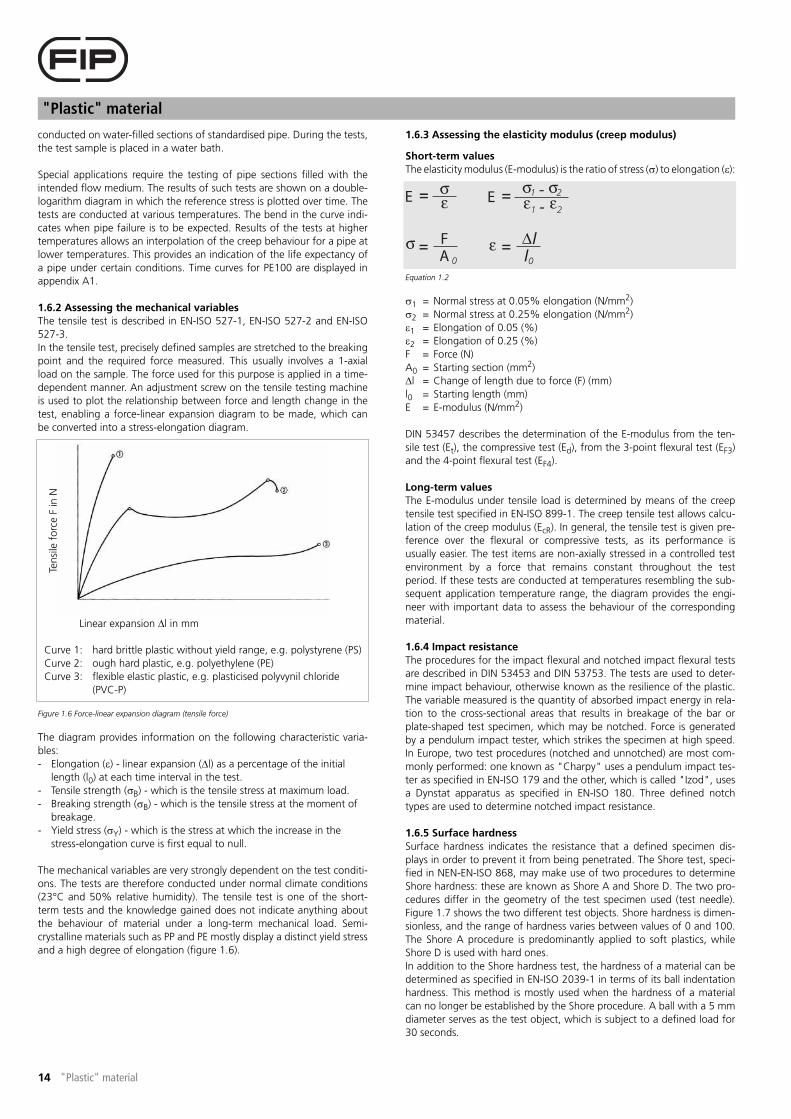
Figure 1.6 Force-linear expansion diagram (tensile force)
The diagram provides information on the following characteristic varia-
bles:
- Elongation (�) - linear expansion (�l) as a percentage of the initial
length (l0) at each time interval in the test.
- Tensile strength (�B) - which is the tensile stress at maximum load.
- Breaking strength (�B) - which is the tensile stress at the moment of
breakage.
- Yield stress (�Y) - which is the stress at which the increase in the
stress-elongation curve is first equal to null.
The mechanical variables are very strongly dependent on the test conditi-
ons. The tests are therefore conducted under normal climate conditions
(23°C and 50% relative humidity). The tensile test is one of the short-
term tests and the knowledge gained does not indicate anything about
the behaviour of material under a long-term mechanical load. Semi-
crystalline materials such as PP and PE mostly display a distinct yield stress
and a high degree of elongation (figure 1.6).
1.6.3 Assessing the elasticity modulus (creep modulus)
Short-term values
The elasticity modulus (E-modulus) is the ratio of stress (�) to elongation (�):
Equation 1.2
�1 = Normal stress at 0.05% elongation (N/mm2)
�2 = Normal stress at 0.25% elongation (N/mm2)
�1 = Elongation of 0.05 (%)
�2 = Elongation of 0.25 (%)
F = Force (N)
A0 = Starting section (mm2)
�l = Change of length due to force (F) (mm)
l0 = Starting length (mm)
E = E-modulus (N/mm2)
DIN 53457 describes the determination of the E-modulus from the ten-
sile test (Et), the compressive test (Ed), from the 3-point flexural test (EF3)
and the 4-point flexural test (EF4).
Long-term values
The E-modulus under tensile load is determined by means of the creep
tensile test specified in EN-ISO 899-1. The creep tensile test allows calcu-
lation of the creep modulus (EcR). In general, the tensile test is given pre-
ference over the flexural or compressive tests, as its performance is
usually easier. The test items are non-axially stressed in a controlled test
environment by a force that remains constant throughout the test
period. If these tests are conducted at temperatures resembling the sub-
sequent application temperature range, the diagram provides the engi-
neer with important data to assess the behaviour of the corresponding
material.
1.6.4 Impact resistance
The procedures for the impact flexural and notched impact flexural tests
are described in DIN 53453 and DIN 53753. The tests are used to deter-
mine impact behaviour, otherwise known as the resilience of the plastic.
The variable measured is the quantity of absorbed impact energy in rela-
tion to the cross-sectional areas that results in breakage of the bar or
plate-shaped test specimen, which may be notched. Force is generated
by a pendulum impact tester, which strikes the specimen at high speed.
In Europe, two test procedures (notched and unnotched) are most com-
monly performed: one known as "Charpy" uses a pendulum impact tes-
ter as specified in EN-ISO 179 and the other, which is called "Izod", uses
a Dynstat apparatus as specified in EN-ISO 180. Three defined notch
types are used to determine notched impact resistance.
1.6.5 Surface hardness
Surface hardness indicates the resistance that a defined specimen dis-
plays in order to prevent it from being penetrated. The Shore test, speci-
fied in NEN-EN-ISO 868, may make use of two procedures to determine
Shore hardness: these are known as Shore A and Shore D. The two pro-
cedures differ in the geometry of the test specimen used (test needle).
Figure 1.7 shows the two different test objects. Shore hardness is dimen-
sionless, and the range of hardness varies between values of 0 and 100.
The Shore A procedure is predominantly applied to soft plastics, while
Shore D is used with hard ones.
In addition to the Shore hardness test, the hardness of a material can be
determined as specified in EN-ISO 2039-1 in terms of its ball indentation
hardness. This method is mostly used when the hardness of a material
can no longer be established by the Shore procedure. A ball with a 5 mm
diameter serves as the test object, which is subject to a defined load for
30 seconds.
Curve 1: hard brittle plastic without yield range, e.g. polystyrene (PS)
Curve 2: ough hard plastic, e.g. polyethylene (PE)
Curve 3: flexible elastic plastic, e.g. plasticised polyvynil chloride
(PVC-P)
Ten
sile
fo
rce F
in
N
Linear expansion �l in mm

15
"Plastic" material
"Plastic" material
Figure 1.7 Test objects for Shore A and Shore D hardness tests
1.7 Thermal properties
1.7.1 Heat expansion coefficient
In determining the heat expansion coefficient, a distinction is made
between the linear expansion coefficient (thermal length expansion coef-
ficient (a�)) and the cubic expansion coefficient (spatial expansion coeffi-
cient (��)). The linear expansion coefficient (��) indicates the amount
that a material with a standard length of one metre will lengthen or shor-
ten under a temperature change of 1 K. The spatial expansion coefficient
(��) indicates the amount that a cubic meter of material will lengthen or
shorten under a temperature change of 1 K. DIN 53752 describes the
tests for the linear and cubic expansion coefficients. The unit of the
expansion coefficient is (1/K), (K-1) or (mm/mK).
1.7.2 Deformation resistance to heat
All property changes are important to the engineer and especially behavi-
ours in response to heat effects. For this reason, various tests are conduc-
ted to ascertain the approximate boundary temperatures below which
deformation does not occur. EN-ISO 75-1 and EN-ISO 75-2 describe
methods of determining heat resistance.
Three procedures are used to determine deformation resistance:
1. Martens (DIN 53462)
2. Vicat
3. ISO/R 75 (ASTM D 640)
The determined variables do not, however, permit any conclusions to be
drawn about the working temperature of the tested plastics. Values
ascertained for plastics are only comparable when they are tested under
identical conditions and procedures. The outside temperature effects of
air or fluid as well as the form and manufacturing method of the samples
have a large influence on the measured results.
1.7.3 Heat conductivity
The heat conductivity or the heat coefficient (), measured as (W/mK), is
a temperature dependent material characteristic that indicates some-
thing about the capacity of a material to conduct heat. An indication of
heat conductivity or insulation capacity (negative thermal conductivity) of
a material can be provided by tests specified in DIN 52612-1 or DIN
52613 (ISO/DIS 8497-1988). The heat conductivity of a substance can be
significantly influenced by the filling, reinforcements, auxiliary materials,
and colouring.
1.7.4 Heat transfer coefficient
The Heat transfer coefficient (�) is an important factor needed to calcu-
late the heat transition coefficient () as well as specific heat conductivity
(l) of a material. The heat conductivity, like the heat transfer coefficient, is
strongly dependent on other influences, such as separation plane, geo-
metry and flow rate of the medium.
1.7.5 Heat transition coefficient
The heat transition coefficient (k) provides information about the insula-
tion capacity of a material. The unit is (W/m2K). The smaller the k-value
is, the higher the insulation capacity of the material. The heat transition
coefficient is computed with the equation:
Equation 1.3
k = Heat transition coefficient ( - )
�w1 = Heat transition coefficient of medium 1 to the wall (W/m2K)
�w2 = Heat transition coefficient of the wall to medium 2 (W/m2K)
= Heat conductivity of the wall (W/mK)
dw = Thickness of the separation wall (m)
1.7.6 Burning behaviour
Plastics are organic compounds that are, by their nature, combustible.
The European standard EN 13501-1 defines a classification system for
material burning behaviour for building products and building structures.
The burning behaviour of finished products (in the manner that they are
used) must be described in terms of the extent to which the material
contribute to the development and spread of fire and smoke in an area
or environment. In the case of fire, building products are exposed to a
fire ignited in a given area. This fire can then grow (increase) and finally
Shore A test needle Shore D test needle
Stage 1: Combustibility
Table 1.1
Class Fire tests Spreading of flames Contribution Practice
F Not tested or does not meet class E Unclassified Undefined Extremely combustible
E EN-ISO 11925-2 (15 sec-Fs<150 mm-20 sec) Spreading of flames 100 kW <2 min. Very high contribution Very combustible
D EN 13823, Figra <750 W/sEN-ISO 11925-2 (30 sec-
Fs<150 mm-60 sec)
Spreading of flames 100 kW >2 min. High contribution Quite combustible
C EN 13823, Figra <120 W/s + Thr <15 MJEN-ISO
11925-2 (30 sec-Fs<150 mm-60 sec)
Spreading of flames 100 kW >10 min. Large contribution Combustible
B EN 13823, Figra <120 W/s + Thr <7.5 MJEN-ISO
11925-2 (30 sec-Fs<150 mm-60 sec)
No spreading of flames Very limited contribution Very difficult to
combust
A2 EN ISO 1182 of EN-ISO 1716 plusEN 13823,
Figra <120 W/s+ Thr <7,5 MJ
No spreading of flames Hardly any contribution Practically
incombustible
A1 EN ISO 1182 = IncombustibleEN-ISO 1716 = Caloric
values
No spreading of flames No contribution Incombustible

"Plastic" material
16 "Plastic" material
spread. The scenario contains three components of fires that correspond
the stages in the development of a fire:
- Combustibility: the starting of a fire by ignition using a small flame on
a small surface/product.
- Smoke production: development and potential spread of fire.
- Burning drops/fragments: outbreak of fire when all combustible
material contribute to the fire potential.
Combustion classification
Stage 2: Smoke production
Stage 3: Burning drops/ fragments
Fire safety
The required fire safety level of a building is not the same in all European
member states. Every member state may make its own regulations to
determine the products that may be used and the combustion class that
is suitable for the circumstances.
1.8 Chemical properties
1.8.1 Chemical resistance
The chemical resistance of PE to contacting media will be treated in detail
in Chapter 2 (table 2.3).
1.8.2 Permeation
Permeation is regarded as the diffusion of a medium through a plastic
(e.g. container wall, shaft wall or pipe wall). Contact between plastic and
chemical medium can, under certain circumstances, result in moisture
expansion or dissolution. Problems can also result from the dislodging of
material by softening and processing agents, as well as from the bleeding
of colouring. Practical testing procedures are presented in DIN 53405
(dislodging) and EN-ISO 183 (bleeding of colouring).
1.8.3 Water absorption
Many plastics tend to absorb water. Due to swelling the dimensional sta-
bility changes. PE is water-repellent, which means that it cannot be
damaged by swelling. The test procedure is described in EN-ISO 62.
1.9 Processing characteristic: Melt index
Determination of the melt-mass flow rate (MFR) as specified in EN-ISO
1133, also known as the melt flow index (MFI), is a standardised testing
method for obtaining a relatively quick and quantitative indication of a
plastic's flow behaviour. The MFR value indicates the amount of thermo-
plastic molten mass pressed through a standardized nozzle during 10
minutes of steady piston force and constant melt temperature. Table 1.4
indicates the test conditions:
The melt volume flow rate (MVR), also known as the melt volume index
(MVI) is used to test the flow behaviour of a molten mass at constant pis-
ton force and defined temperature. The unit of the MRV is cm3/10 min.
1.10 Physics of plastics
1.10.1 Residual stress
All plastic components possess a certain residual stress potential, which is
not attributable to external forces but exists on account of manufactu-
ring and cooling conditions. In the process of extruding plates, pipes and
profiles, molten mass is pressed through a die, causing the macromole-
cule to be stretched. Subsequently, it is cooled and fixed in a sizing unit.
Since the pipe is cooled from the outside in, the pipe wall cools at sub-
stantially different rates.
This cooling behaviour has consequently effects on the structure and/or
thickness of the pipe shell.
In the pipe wall results at the initially cooled side residual compressive stress
(�D) and at the subsequently cooled side residual tensile stress (�T) (figure
1.8). These stresses may be significantly reduced by means of tempering
(i.e. reheating the pipe to a defined temperature). The subsequent heating
reduces the existing residual stresses, which have substantial effects on the
dimensional stability, retraction, shrinkage and service life of the pipe.
Dimensional stability is extremely important for pipes and components,
since a change in diameter can have negative consequences for the leak
tightness of connections. Usually, PE pipes are tempered.
Figure 1.8 Stress in the pipe wall
The stresses normally equally offset each other. If external or internal
influences cause the stresses to fall into disequilibrium, the component
can be deformed.
However, the cooling procedure is not the only cause of residual stresses
in a plastic component. The following sections describe other types of
stress that have residual effects on a pipe or fitting.
Class Description
s3 Great deal of smoke production
s2 Average smoke production
s1 Little smoke production
Class Description
d2 Fragments burning longer than 10 sec.
d1 Fragments burning shorter than 10 sec.
d0 No production of burning fragments
Test specification Test conditions
ISO 1133 Temperature (°C) Load (kg)
1 190 2.16
6 190 10.00
12 230 2.16
18 190 5.00
20 230 5.00Table 1.2
Table 1.3
Table 1.4 Test specifications and conditions for determining the MFR value
1
2 4
3
1 Pipe wall exterior
2 Pipe wall interior
3 �D = compressive stress
4 �T = tensile stress

17
"Plastic" material
"Plastic" material
- Residual orientation stress
This strongly depends on cooling patterns. The speed with which the
orientation in longitudinal and transverse directions is fixed ("frozen" in
the technical terminology), which is to say the strength with which heat
dissipation acts on both orientation states, raises or lowers the level of
orientation, causing stresses to be increased or decreased.
- Residual after-pressure stress
Residual after-pressure stress mostly occurs in injection-moulding compo-
nents, although it can also be caused by extrusion processes. For
example, an extrusion process is typically involved in the manufacture of
solid bars, which have to be subject to after-pressure in order to prevent
cavities (holes) or bubbles (empty spaces) from forming. If the pressure
during cooling of the fittings is too high, a residual pressure remains in
the fitting that can lead to its deformation.
- Residual crystallisation stress
This stress originates in the crystallisation phase of semi-crystalline ther-
moplastics. Crystallites forming when the molten mass is cooling are sub-
ject to contraction (volume change). Cooling that occurs in an uneven
manner and results in a temporarily irregular crystallisation process can
cause structural strains.
- Stress reduction
A remedial measure to abate frozen stresses (residual stresses) is the tem-
pering of the pipe. Besides reducing residual stress, tempering can insti-
gate an after-crystallisation process (in semi-crystalline plastics), which
can have a positive effect on the properties of plastic.
Tempering is a special temperature control or heat treatment, the para-
meters of which depend on the plastic involved. During tempering, care
must be taken not to set the heat high enough to generate reset forces
and cause deformation. As a rule, the parameters depend on the thick-
ness of the tempered fittings and the level of the stress profile.
It is important that the products are slowly cooled after storage to pre-
vent stresses from recurring as a result of local temperature differences.
1.10.2 Flexural, thermal, tensile and compressive stresses
These types of stress are discussed in detail in chapter 6, as they repre-
sent important criteria in planning and constructing pipe systems. They
are basic elements in the construction and manufacture of plastic buil-
ding supplies.
1.10.3 Orientation
Orientation designates the arrangement of macromolecules in a plastic
component.
Initially, the macromolecules of a plastic are in a disordered state ("knot-
ted ball"). The processing procedures (e.g. extrusion or injection moul-
ding) force the macromolecules through dies, moulds, extractor units,
cooling processes, etc., aligning them in a certain direction. They can be
arranged both longitudinally (in the case of extrusion in the direction that
the fitting is extracted) or transversely to the centre line. The nature and
alignment of the orientations have very great effects on the mechanical
properties and stability of the product. Orientation results from shear and
expansion forces.
Shear forces are created in both injection moulding and extrusion proces-
ses. They are produced by the shear strain of adjacent strata of molten
material flowing at different velocities, for example when molten mate-
rial is clinging to the wall of the mould. Expansion forces are caused by
the flow of molten material through constrictions or flow channels, such
as nozzles. In extruded semi-finished products (e.g. plates, pipes, pro-
files), the preferred orientation is longitudinal to the extrusion direction
and less optimally in the transverse direction. In opposition to the pressed
semi-finished products in which no distinct orientation is the result, the
properties of extruded semi-finished products are anisotropic, which
means strongly dependent on orientation. Mechanical properties such as
strength, impact resistance and impact strength are better in anisotropic
semi-finished products oriented in the direction of extrusion and poorer
in the case of transverse orientation such as isotropic semi-finished
products. Since thermal elasticity is only utilised in temperatures above
freezing (or crystallite melting temperature), it is not possible to remedy
orientation by tempering.
1.10.4 Retraction
The term "retraction" is understood as a change in the fitting as a result
of forced length changes of the macromolecule. This process occurs
especially in extrusion procedures. The molecule is consequently stret-
ched by the extrusion die and/or extractor unit, usually in a axial (i.e. lon-
gitudinal) direction. As soon as the macromolecule again has the
opportunity to resume its original shape, a length change counteracts
the stretching orientation. This is called the "memory effect". Rapid coo-
ling of the molten plastic fixes it in a given (frozen) state. Heating the
plastic above the "freezing temperature" activates the above-mentioned
"memory effect" and the macromolecule attempts to return to its origi-
nal ("knotted") state. Retraction is therefore a pure contraction in length
(length change) as a consequence of orientation of the macromolecule in
the fitting.
1.10.5 Contraction
The term shrinkage designates a volume contraction of the plastic fittings.
Like other materials, a volume increase occurs when plastic is exposed to a
temperature rise.
The cooling of the material instigates the inverse process. Since this effect
is well-known, this phenomenon must be considered when constructing
tools and fittings if a manufacturer wishes to produce technically high-
grade products. There are two kinds of shrinkage:
- processing shrinkage
- after-shrinkage
1.10.6 Notch effect
The calculation of component stresses is ideally based on tensile and flexu-
ral stresses. The stresses that actually occur are however influenced by a
number of factors (e.g. scratches, material inhomogeneities, structural
composition of the fitting, etc.), all of which result in deviation from the
ideal state. The size of notches, the radius of notch bases and the types of
load have important effects on the strength of a fitting. The deeper and
sharper that a notch is formed, the higher the stress peak at the notch
base and, consequently, the greater the danger of damage to the compo-
nent. It is therefore advisable to make the smallest possible notches that
are round (circular) shaped.

"Plastic" material
18 "Plastic" material
1.11 Chapter summary
Plastic Plastic is divisible into three main groups: thermoplastics, thermosets and elastomers.
Elastomers Elastomers are better known as rubber. They are wide-meshed, spaciously interlinked synthetic or natural rubber
compounds. Interlinking is enhanced by vulcanisation.
Thermosets Thermosets possess a close-meshed interlinked macromolecular structure. They are hard, brittle and no longer
plasticisable (meltable).
Thermoplastics Thermoplastics can be divided into amorphous and semi-crystalline thermoplastics.
Polyolefin This compound belongs to the group of semi-crystalline thermoplastics. Its most important representatives are
polyethylene (PE) and polypropylene (PP).
Plastic processing machines Extruders, injection moulding machines and calendars (not discussed in this manual) are machines used to manu-
facture plastic semi-finished products.
Extruder An extruder is responsible for plasticising raw materials. Used, for example, in the manufacture of pipes, profiles
and plates. Continuous process.
Injection moulding machine Injection moulding involves a discontinuous manufacturing process. The screw performs both a rotational and an
axial motion. Important parameters for injection moulding are: temperature, time and pressure. Process steps are:
plasticisation, injection and cooling.
Internal pressure creep test Simulates the life expectancy of a plastic pipe under an internal pressure load. The associated reference stress
(�ref) is a function of the internal pressure, mean pipe diameter and wall thickness. It is calculated using the boiler
formula.
Short-term tensile test The short-term tensile test involves stretching a sample bar to the breaking point. The result provides an indica-
tion of the mechanical values of the tested material. The most important mechanical values are: expansion, ten-
sile strength, breaking strength and breaking strain.
Elasticity modulus (Creep modulus) The elasticity modulus is the ratio of stress to expansion.
Creep tensile test The creep tensile test is used to determine the creep modulus.
Impact resistance Impact resistance is determined by means of the impact flexural test and the notched impact flexural test (the lat-
ter involving defined notches in the sample). Most important test methods are the "Charpy" and "Izod" tests.
Surface hardness Designates the resistance against the penetration of the test specimen. Most important procedures are Shore A,
Shore D and ball indentation hardness.
Heat expansion coefficient The heat expansion coefficient is an important parameter in plastics. A statement of this mechanical value is usu-
ally accompanied by an indication of the linear expansion coefficient (��) (in literature, this is mostly expressed as
the mean linear longitudinal expansion coefficient �).
Heat resistance This term designates the temperature limits of thermoplastics under the effects of heat. Testing procedures are
Martens, Vicat and ISO/R 75. No conclusions about working temperatures are possible.
Heat conductivity Variable indicating the capacity of a material to conduct heat. Filling, reinforcements, auxiliary material and
colouring affect heat conductivity.
Heat transfer coefficient This variable is used to calculate the heat transition coefficient. It depends on the separation plane, geometry and
flow speed of the medium.
Heat transition coefficient The heat transition coefficient (k) provides information about the insulating capacity of a material.
Burning behaviour Plastics are organic compounds and therefore combustible by nature.
Permeation Diffusion tendency of a material, which is the permeability of fluids or gaseous elements through the plastic.
Water absorption Many plastics tend to absorb water (swelling). This means that the stability of the plastic is no longer assured. PE
has hardly any tendency to absorb water.
Melt index The melt index indicates the flow capacity of a plasticised plastic. Previously known as the MFI value, it is now
referred to as the MFR value.
Residual stress During an extrusion process, residual stresses build up in pipes as a result of cooling procedures at high extraction
speeds, for example. These stresses can be reduced in pipes by adopting special temperature controls or heat tre-
atments (tempering).
Residual orientation stress Dependent on cooling conditions. Increasing cooling speed raises the stress potential in pipes.
Residual after-pressure stress Phenomenon in injection moulding components. Residual after-pressure stress can also occur in extrusion com-
ponents when, for example, after pressure has to be used in manufacturing solid bars to prevent bubbles and
cavities.
Residual crystallisation stress This occurs in semi-crystalline plastics (e.g. PE) due to crystallite formation during the cooling phase.
Tempering Heat treatment to reduce or eliminate residual stress potentials.
Orientation Alignment of the macromolecules by external forces (e.g. extraction speed).
Retraction Retraction designates a longitudinal contraction (negative length change) in the direction in which the macromo-
lecules are oriented.
Shrinkage In contrast to retraction, shrinkage designates a volume contraction (negative volume change) as a result of coo-
ling processes. In contrast to retraction, a volume change is discernible in every plastic component. These volume
changes are seen in the fitting structure and in the die or mould structure.
Notch effect The notch effect affects the strength of the component. Grooves, scratches, inhomogenities or a component's
structural form can have adverse affects on the fittings.

19
Material properties of PE
Material properties of PE
2 Material properties of PE
2.1 General material properties of polyethylene (PE)
Thermoplastics are sub-divisible into two groups: amorphous and semi-
crystalline thermoplastics. Polyethylene is a polyolefin, which forms a
separate group among the semi-crystalline thermoplastics. Polyethylene,
abbreviated PE, is an umbrella term for a group on individually distinctive
PE types.
In specific, the following PE types are distinguished:
- PE-LD (Density: 0.9 - 0.91 g/cm3)
- PE-LLD (Density: 0.91 - 0.93 g/cm3)
- PE-MD (Density: 0.93 - 0.94 g/cm3)
- PE-HD (Density: 0.94 - 0.965 g/cm3)
It is PE-HD that is of primary interest for use in plastic pipe construction,
although PE-MD is also used in the gas-pipe sector. The characteristics of
PE-MD will, however, not be further detailed in this Specification Manual.
PE-HD (high density) has a high density with an average molar mass
(MM) between 40,000 and 400,000 g/mol (depending on the manufac-
turing process and the process parameters). In comparison, PE-LD (low
density) has a lower density and therefore a molar mass of up to 600,000
g/mol. PE-HD is manufactured as a polymer either by using a medium
pressure procedure (Phillips) or a low pressure procedure (Ziegler). Poly-
mers based on ethylene offer semi-finished product manufacturers a
great deal of latitude in making modifications. For pipe and fitting manu-
facture, it is the mechanical properties of PE that are foregrounded (elas-
tic stiffness).
As mentioned at the beginning of this chapter, PE is to be understood as
an umbrella term for a thermoplastic group. For instance, PE includes the
substance PE100.
More attention will be paid to the significance of the numerical values
(e.g. PE100) in the course of chapter 4. For the sake of simplification, the
label "PE" will be used throughout the rest of this manual to designate
PE-HD. PE is resistant to acids, bases, saline solutions, water, alcohol and
oil. Under 60°C, it is practically insoluble in nearly all organic solvents. PE
can readily withstand ionised rays if they are not too strong and will not
become radioactive itself. It is furthermore readily weldable, although
there are problems involved in gluing and decorating PE. The surfaces
will allow imprinting or painting to adhere only after physical or chemical
pre-treatment. Bonding can only be done with the help of contact glue,
although such adhesive bonds cannot be subject to very high mechanical
loads.
2.2 Properties of PE100
Unit Test method Value
Density
at 23°C
g/cm3 ISO 1183 0.958
Elasticity
modulus
N/mm2 ISO 527 900
Tensile creep
modulus
N/mm2 ISO 899 850
Bending creep
modulus
N/mm2 DIN 54852-Z4 1200
Tensile strength
at 23°C
N/mm2 ISO 527 23
Elongation
at break
% ISO R 527 >600
Linear expansion
coefficient
mm/mK DIN 53752 0.13 - 0.19
Indentation
hardness
N/mm2 ISO 2039 36 - 46
Ignition
temperature
°C - ~350
Thermal
conductivity
W/m . K DIN 52612 0.23
Shore hardness ISO 868 65
Crystallite
melting range
°C ~130
Operational
temperature range
°C - -40 - +100
Melt flow rate
MFR 190/5
g/10min ISO 1133 0.43
Table 2.1

Material properties of PE
20 Material properties of PE
Table 2.2
Properties PE Benefits
Impact-resistant and tough Unbreakable at temperatures > 5ºC
Elastic Suitable for underground pipes through adjustment to
local ground movement
Thermal resistant Application possible between -40ºC and 100ºC
Smooth internal wall Low blockage risk due to low deposit/residue effects
Wear resistant Lower costs due to relatively long life
Weather-resistant / UV resistant Application in open air unrestricted through colouring
with carbon black
Chemical Resistance Suitable for the transport of polluted waste water
Poor heat conductivity No condensation during short periods of cooling
Non-toxic Environmentally friendly
Insulating Non-conductive
Highly suitable for welding Easy installation using butt-welding and electrofusion
techniques
Homogeneous welded joints End load resistant and leak proof
Prefabrication Reduces on-site installation times
Light in weight Cost-saving in transport and handling

21
Material properties of PE
Material properties of PE
2.3 Chemical resistance
Table 2.3 indicates the chemical resistance of PE to various media at a
number of temperatures.
In transporting chemicals, consideration needs to be given to the follo-
wing factors:
- the medium
- concentration of the medium
- temperature
- duration of the load
- flow volume
The elastomer resistance list is intended as an aid for determining the
suitability of a given seal. The indicated values refer to the volume of swel-
ling for the rubber compound, which is only one of the indications con-
cerning resistance. Chemical damage to the polymer chain can also lead to
changes in mechanical properties such as tensile strength, elasticity at
break, etc. The most commonly indicated values are measured at a tem-
perature of 20°C. A longer exposure to a higher temperature can create
more aggressive conditions that reduce the life-span of elastomers.
Empty field = The material has not been tested on this medium at this
temperature.
1 Little of no effect: volume change <10%, the elastomer can display
slight swelling and/or loss of physical characteristics under heavy
conditions.
2 Possible change of physical qualities: volume change of 10-20%, the
elastomer can display swelling and a change of physical
characteristics, can be suitable for structural applications.
3 Substantial change in physical characteristics: the elastomer displays a
substantial change in volume and physical qualities.
4 Excessive change: elastomer is unsuitable.
Empty field = The elastomer has not been tested on this medium.
Abbreviations used:
PE = polyethylene
NBR = acrylonitrile butadiene
EPDM = ethylene propylene
FPM = fluorocarbon
SBR = styrol butadiene
Explanation of symbols used for PE pipes and fittings:
+ Resistant: based on performed tests, PE is in general a suitable
material for this application
/ Limited resistance: further research required
- Non-resistant

Material properties of PE
22 Material properties of PE
Fluid Concentration Pipe and fittings Elastomeric seals
HDPE NBR EPDM FPM SBR
Name Formula Remark °C °C °C °C °C
20 40 60 20 20 20 20
Acetaldehyde CH3CHO Aqueous solution 40% + + / 4 2 4 3
Acetaldehyde CH3CHO Technically pure 100% + / / 4 2 4 3
Acetic Acid CH3COOH Aqueous solution 10% + + + 4 3/4 4 4
Acetic Acid CH3COOH Aqueous solution 30% + + + 4 4 4 4
Acetic Acid CH3COOH Aqueous solution 60% + + + 4 4 4 4
Acetic Acid CH3COOH Aqueous solution 80% / / - 4 4 4 4
Acetic Acid CH3COOH Technically pure 100% + + / 4 4 4 4
Acetic Acid Anhydride (CH3CO)2O Technically pure 100% + / 4 2 4 2
Acetone CH3COCH3 Aqueous solution 10% + + + 4 1 4 2/3
Acetone CH3COCH3 Technically pure 100% / / 4 1 4 2/4
Acetophenone CH3COC6H5 Technically pure Indetermined + + + 4 1 4 4
Acrylonitrile CH2=CH-CN Technically pure 100% + + + 4 4 4 3
Adipic Acid HOOC(CH2)4COOH Aqueous solution Saturated + + + 1 1 1 1
Alcohol 40% +
Alcoholic Spirits Comm. Comp. + +
Allyl Alcohol CH2=CH-CH2OH Aqueous solution 96% + + +
Alum Al2(SO4)3K2SO4 4H2O Aqueous solution Solution + + + 2 1 1 1
Alum Al2(SO4)3K2SO4 4H2O Aqueous solution Saturated + + + 2 1 1 1
Aluminium Acetate (CH3COO)3Al Aqueous solution Saturated + + + 2 1 4 4
Aluminium Bromide AlBr3 Aqueous solution Saturated + + + 1 1 1 1
Aluminium Chloride AlCl3 Aqueous solution All + + + 2 1 1 1
Aluminium Fluoride AlF3 Aqueous solution Saturated + + + 2 1 1 1
Aluminium Nitrate Al(NO3)3 Aqueous solution Saturated + 1 1 1 1
Aluminium Sulfate Al2(SO4)3 Aqueous solution 10% + + + 2 1 1 1
Aluminium Sulfate Al2(SO4)3 Aqueous solution Saturated + + + 2 1 1 1
Ammonia NH3 Aqueous solution Solution + + + 2 1 3 2
Ammonia Gas NH3 Aqueous solution Saturated + + + 2 1 3 2
Ammonia Gas NH3 Technically pure 100% + + + 2 1 3 2
Ammonium Acetate CH3COONH4 Aqueous solution Saturated + + +
Ammonium Bifluoride NH4FHF Aqueous solution Saturated + + +
Ammonium Carbonate (NH4)2CO3 Aqueous solution 100% + + + 2 1 2 2
Ammonium Chloride NH4Cl Aqueous solution Saturated + + + 1 1 1 1
Ammonium Fluoride NH4F Aqueous solution 25% + + + 1 1 1 1
Ammonium Fosfate (NH4)3PO4 X H2O All + + + 1 1 1 1
Ammonium Hydroxide NH4OH Aqueous solution Solution + + + 4 1 2 4
Ammonium Hydroxide NH4OH Aqueous solution Saturated + + + 4 1 2 4
Ammonium Nitrate NH4NO3 Aqueous solution Saturated + + / 2 1 1 1
Ammonium Sulfate (NH4)2SO4 Aqueous solution All + + + 1 1 1 1
Ammonium Sulfhydrate NH4OH(NH4)2SO4 Aqueous solution Solution +
Ammonium Sulfhydrate NH4OH(NH4)2SO3 Aqueous solution Saturated +
Ammonium Sulfide (NH4)2S Aqueous solution 10% + + + 1 1 1 1
Ammonium Sulfide (NH4)2S Aqueous solution Saturated + + + 1 1 1 1
Amyl Acetate CH3COO(CH2)4CH3 Technically pure 100% + + + 4 2 4 3
Amyl Alcohol CH3(CH2)3CH2OH 100% + + / 2 2 2 1
Amyl Chloride CH3(CH2)4Cl Technically pure 100% - 4 1 4
Aniline C6H5NH2 Technically pure 100% / 4 2/3 1 3
Aniline Chlorhydrate C6H5NH2HCl Aqueous solution Saturated / / / 2 2 1 1
Anthraquinone Sulfonic
Acid
Solution +
Antimony Trichloride SbCl3 Aqueous solution 90% + + + 1 1 1 1
Aqua Regia 3HCl+1HNO3 100% - - - 4 4 2/3 4
Arsenic Acid H3AsO4 Saturated + +
Barium Carbonate BaCO3 Aqueous solution All + + +
Barium Chloride BaCl2 Aqueous solution All + + + 1 1 1 1
Barium Hydroxide Ba(OH)2 Aqueous solution Saturated + + + 1 1 1 1
Barium Nitrate Ba(NO3)2 Aqueous solution Saturated + + +
Barium Sulfate BaSO4 Aqueous solution Saturated + + + 1 1 1 1
Barium Sulfide BaS Aqueous solution Saturated + + + 1 1 1 2
Beer 100% + + + 1 1 1 1
Benzaldehyde C6H5CHO Aqueous solution Saturated + + + 4 2 4 3
Benzene C6H6 Technically pure 100% / - - 4 4 3 4
Benzene + Benzine 20/80% / - - 2/3 4 2 4

23
Material properties of PE
Material properties of PE
Benzene Sulfonic Acid C6H5SO3H Aqueous solution 10% - 4 4 1 4
Benzine (Free Of Pb And
Aromatic)
C5H12÷C12H26 Technically pure 100% + + / 4 4 1 4
Benzoic Acid C6H5COOH Aqueous solution Saturated + + + 4 4 1 4
Benzyl Alcohol C6H5CH2OH Technically pure 100% + + / 4 1 1 4
Bleaching Lye NaClO+NaCl 12,5% Cl / / 4 1 1 4
Borax Na2B4O7 Aqueous solution All + + + 1 1 1 1
Boric Acid H3BO3 Aqueous solution Saturated + + + 1 1 1 1
Brine Comm. Comp. +
Bromic Acid HBrO3 10% + + + 4 1 1 4
Bromine,Liquid Br2 Technically pure 100% - 4 3 2 4
Bromine,Liquid Br2 High - 4 4 1 4
Butadiene CH2=CH-CH=CH2 Gas 100% + 3 4 2 4
Butane Gas CH3CH2CH2CH3 100% + + + 2 4 2 4
Butanediol OHCH2CH2CH2CH2OH Aqueous solution 10% + + +
Butanediol OHCH2CH2CH2CH2OH Aqueous solution Concentrated / - -
Butyl Acetate CH3COOCH2CH2CH2CH3 Technically pure 100% / / / 4 2 4 4
Butyl Alcohol CH3(CH2)3OH Technically pure 100% + + + 1 2 1 1
Butyl Ether (CH3(CH2)3)2O Technically pure 100% / - - 4 3 4 4
Butyl Phenol C4H9C6H4OH Technically pure 100% - 4 4 2 4
Butyl Phthalate HOOCC6H4COOC4H9 Technically pure 100% + / /
Butylene CH2=CH-CH2CH4 Liquid 100% - 2 4 1 4
Butylene Glycol OHCH2-CH=CH-CH2OH Technically pure 100% + + + 1 1 1 1
Butylene CH2=CH-CH2CH3 Technically pure 100% - 2 4 1 4
Butyric Acid CH3CH2CH2COOH Aqueous solution 20% + + /
Butyric Acid CH3CH2CH2COOH Technically pure 100% + + /
Calcium Acetate Ca(CH3COO)2 Aqueous solution Saturated + + + 2 1 4 4
Calcium Bisulfite Ca(HSO3)2 Aqueous solution Saturated + + + 2 1 2 2
Calcium Carbonate CaCO3 Aqueous solution All + + + 1 1 1 1
Calcium Chlorate Ca(ClO3)2 Aqueous solution Saturated + + + 1 1 1 1
Calcium Chloride CaCl2 Aqueous solution All + + + 1 1 1 1
Calcium Hydroxide Ca(OH)2 Aqueous solution All + + + 1 1 1 1
Calcium Hypochloride Ca(CIO)2 Aqueous solution Saturated + + + 4 1 1 4
Calcium Nitrate Ca(NO3)2 Aqueous solution 50% + + + 1 1 1 1
Calcium Sulfate CaSO4 Aqueous solution Saturated + + +
Calcium Sulfide CaS Aqueous solution Saturated / / / 1 1 1 2
Camphor Oil Comm. Comp. - -
Carbon Dioxide CO2+H2O Aqueous solution Indetermined + + + 1 1 1 1
Carbon Dioxide CO2 Gas 100% + + + 1 1 1 1
Carbon Disulfide CS2 Technically pure 100% / - 4 4 1 4
Carbon Monoxid CO Gas 100% + + + 2 2 1 2
Carbon Tetrachloride CCl4 Technically pure 100% -
Carbonic Acid H2CO3 Aqueous solution Saturated + + +
Chloramine C6H5SO2NNaCl Aqueous solution Solution +
Chloric Acid HClO3 Aqueous solution 20% /
Chlorine Cl2 Wet All / - 4 3 1 4
Chlorine Cl2 Gas 100% / / - 4 2 4 4
Chlorine Cl2 Technically pure 100% -
Chlorine Water Cl2+H2O Saturated / /
Chloro Benzene C6H5Cl Technically pure 100% / - -
Chloro Sulfonic Acid HClSO3 Technically pure 100% - - -
Chloroform CHCl3 Technically pure 100% - 4 4 2 4
Chrome Alum KCr(SO4)2 Aqueous solution Saturated + + +
Chrome Alum KCr(SO4)2 Indetermined + + +
Chromic Acid CrO3+H2O Aqueous solution 10% / - - 4 2/3 1 4
Chromic Acid CrO3+H2O Aqueous solution 30% / - - 4 2/3 1 4
Chromic Acid CrO3+H2O Aqueous solution 50% / - - 4 2/3 1 4
Citric Acid C3H4(OH)(COOH)3 Aqueous solution 50% + + + 2 1 1 2
Compressed Air with Oil 100% + +
Copper Acetate Cu(COOCH3)2 Saturated + 2 1 4 4
Copper Chloride CuCl2 Aqueous solution Saturated + + + 1 1 1 1
Copper Fluoride CuF2 Aqueous solution All + + + 2 1 1 1
Copper Nitrate Cu(NO3)2 Aqueous solution Indetermined + + + 2 1 1 1
Fluid Concentration Pipe and fittings Elastomeric seals
HDPE NBR EPDM FPM SBR
Name Formula Remark °C °C °C °C °C
20 40 60 20 20 20 20
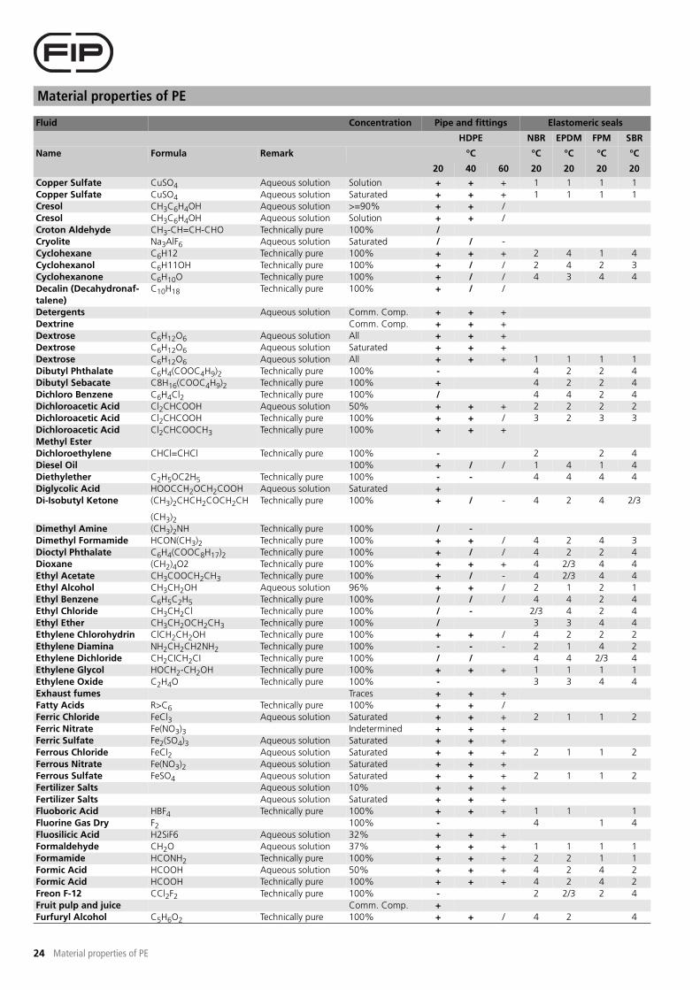
Material properties of PE
24 Material properties of PE
Copper Sulfate CuSO4 Aqueous solution Solution + + + 1 1 1 1
Copper Sulfate CuSO4 Aqueous solution Saturated + + + 1 1 1 1
Cresol CH3C6H4OH Aqueous solution >=90% + + /
Cresol CH3C6H4OH Aqueous solution Solution + + /
Croton Aldehyde CH3-CH=CH-CHO Technically pure 100% /
Cryolite Na3AlF6 Aqueous solution Saturated / / -
Cyclohexane C6H12 Technically pure 100% + + + 2 4 1 4
Cyclohexanol C6H11OH Technically pure 100% + / / 2 4 2 3
Cyclohexanone C6H10O Technically pure 100% + / / 4 3 4 4
Decalin (Decahydronaf-
talene)
C10H18 Technically pure 100% + / /
Detergents Aqueous solution Comm. Comp. + + +
Dextrine Comm. Comp. + + +
Dextrose C6H12O6 Aqueous solution All + + +
Dextrose C6H12O6 Aqueous solution Saturated + + +
Dextrose C6H12O6 Aqueous solution All + + + 1 1 1 1
Dibutyl Phthalate C6H4(COOC4H9)2 Technically pure 100% - 4 2 2 4
Dibutyl Sebacate C8H16(COOC4H9)2 Technically pure 100% + 4 2 2 4
Dichloro Benzene C6H4Cl2 Technically pure 100% / 4 4 2 4
Dichloroacetic Acid Cl2CHCOOH Aqueous solution 50% + + + 2 2 2 2
Dichloroacetic Acid Cl2CHCOOH Technically pure 100% + + / 3 2 3 3
Dichloroacetic Acid
Methyl Ester
Cl2CHCOOCH3 Technically pure 100% + + +
Dichloroethylene CHCl=CHCl Technically pure 100% - 2 2 4
Diesel Oil 100% + / / 1 4 1 4
Diethylether C2H5OC2H5 Technically pure 100% - - 4 4 4 4
Diglycolic Acid HOOCCH2OCH2COOH Aqueous solution Saturated +
Di-Isobutyl Ketone (CH3)2CHCH2COCH2CH
(CH3)2
Technically pure 100% + / - 4 2 4 2/3
Dimethyl Amine (CH3)2NH Technically pure 100% / -
Dimethyl Formamide HCON(CH3)2 Technically pure 100% + + / 4 2 4 3
Dioctyl Phthalate C6H4(COOC8H17)2 Technically pure 100% + / / 4 2 2 4
Dioxane (CH2)4O2 Technically pure 100% + + + 4 2/3 4 4
Ethyl Acetate CH3COOCH2CH3 Technically pure 100% + / - 4 2/3 4 4
Ethyl Alcohol CH3CH2OH Aqueous solution 96% + + / 2 1 2 1
Ethyl Benzene C6H5C2H5 Technically pure 100% / / / 4 4 2 4
Ethyl Chloride CH3CH2Cl Technically pure 100% / - 2/3 4 2 4
Ethyl Ether CH3CH2OCH2CH3 Technically pure 100% / 3 3 4 4
Ethylene Chlorohydrin ClCH2CH2OH Technically pure 100% + + / 4 2 2 2
Ethylene Diamina NH2CH2CH2NH2 Technically pure 100% - - - 2 1 4 2
Ethylene Dichloride CH2CICH2CI Technically pure 100% / / 4 4 2/3 4
Ethylene Glycol HOCH2-CH2OH Technically pure 100% + + + 1 1 1 1
Ethylene Oxide C2H4O Technically pure 100% - 3 3 4 4
Exhaust fumes Traces + + +
Fatty Acids R>C6 Technically pure 100% + + /
Ferric Chloride FeCl3 Aqueous solution Saturated + + + 2 1 1 2
Ferric Nitrate Fe(NO3)3 Indetermined + + +
Ferric Sulfate Fe2(SO4)3 Aqueous solution Saturated + + +
Ferrous Chloride FeCl2 Aqueous solution Saturated + + + 2 1 1 2
Ferrous Nitrate Fe(NO3)2 Aqueous solution Saturated + + +
Ferrous Sulfate FeSO4 Aqueous solution Saturated + + + 2 1 1 2
Fertilizer Salts Aqueous solution 10% + + +
Fertilizer Salts Aqueous solution Saturated + + +
Fluoboric Acid HBF4 Technically pure 100% + + + 1 1 1
Fluorine Gas Dry F2 100% - 4 1 4
Fluosilicic Acid H2SiF6 Aqueous solution 32% + + +
Formaldehyde CH2O Aqueous solution 37% + + + 1 1 1 1
Formamide HCONH2 Technically pure 100% + + + 2 2 1 1
Formic Acid HCOOH Aqueous solution 50% + + + 4 2 4 2
Formic Acid HCOOH Technically pure 100% + + + 4 2 4 2
Freon F-12 CCl2F2 Technically pure 100% - 2 2/3 2 4
Fruit pulp and juice Comm. Comp. +
Furfuryl Alcohol C5H6O2 Technically pure 100% + + / 4 2 4
Fluid Concentration Pipe and fittings Elastomeric seals
HDPE NBR EPDM FPM SBR
Name Formula Remark °C °C °C °C °C
20 40 60 20 20 20 20

25
Material properties of PE
Material properties of PE
Gelatine 100% + + + 1 1 1 1
Glycerine C3H5(OH)3 Aqueous solution All + + + 1 1 2 1
Glycocoll NH2CH2COOH Aqueous solution 10% + +
Glycolic Acid HOCH2COOH Aqueous solution 37% + + +
Gas containing:
- Carbon Dioxide CO2 Gas All + + +
- Carbon Monoxid CO Gas All + + +
- Hydrochloric Acid HCL Gas All + + +
- Hydrochloric Acid HCL Gas All + + +
- Hydrofluoric Acid HF Gas < 0,1 % + + +
- Nitrous Vapours NO, NO2, N2O3, NOx Gas < 0,1 % + + +
- Nitrous Vapours NO, NO2, N2O3, NOx Gas 5% + + +
- Oleum H2SO4 + SO3 Gas < 0,1 % - - -
- Oleum H2SO4 + SO3 Gas 5% - - -
- Sulphur Dioxide Liquid SO2 Gas All + + +
- Sulphur Trioxide SO3 Gas < 0,1 % - - -
- Sulphuric Acid H2SO4 Gas All + + +
Heptane C7H16 Technically pure 100% + / - 1 4 1 4
Hexane C6H14 Technically pure 100% + / / 1 4 1 4
Hydrazine Hydrate NH2-NH2 H2O Aqueous solution Solution + + + 2 1 1
Hydrobromic Acid HBr 10% + + + 3 2 1 3
Hydrobromic Acid HBr 48% + + + 4 1 1 4
Hydrochloric Acid HCl Aqueous solution 10% + + +
Hydrochloric Acid HCl Aqueous solution 30% + + + 2/3 1 2 2/3
Hydrochloric Acid HCl Aqueous solution 5% + + +
Hydrochloric Acid HCl Aqueous solution Saturated + + +
Hydrocyanic Acid HCN Aqueous solution Solution + + + 2 2 1 2
Hydrocyanic Acid HCN Technically pure + + + 2 2 1 2
Hydrofluoric Acid HF Aqueous solution 10% + + / 4 3 2/3 3
Hydrofluoric Acid HF Aqueous solution 40% + / / 4 3 2/3 3
Hydrofluoric Acid HF Aqueous solution 70% + / / 4 3 2/3 3
Hydrogen Gas H2 100% + + + 2 1 1 4
Hydrogen Peroxide H2O2 Aqueous solution 10% + + + 2 1 1 2
Hydrogen Peroxide H2O2 Aqueous solution 50% + + / 2 1 1 2
Hydrogen Peroxide H2O2 Aqueous solution 90% + - - 2 1 1 2
Hydrogen Sulfide H2S Aqueous solution Saturated + + +
Hydrogen Sulfide H2S 100% + + /
Hydroquinone C6H4O2 Aqueous solution Saturated + + + 3 4 2 4
Hydroxylamine Sulphate (NH2OH)2-H2SO4 Aqueous solution All + + +
Iodine Dry And Wet I2 3% / - 1 2 1 1
Iso-Octane C8H18 100% / / - 1 4 1 4
Isopropyl Alcohol (CH3)2CHOH Technically pure 100% + + + 2 1 1 2
Isopropyl Ether (CH3)2CHOCH(CH3)2 Technically pure 100% / - - 2/3 3 4 4
Lactic Acid CH3CHOHCOOH Aqueous solution <=28% + + + 2 1 1 3
Lanoline Comm. Comp. + + + 1 4 1 4
Lard Oil Comm. Comp. +
Lead Acetate Pb(CH3COO)2 Aqueous solution Saturated + + + 1 1 4 4
Lead Chloride PbCl2 Aqueous solution Saturated + +
Lead Nitrate Pb(NO3)2 Aqueous solution Saturated + 1 1 1 1
Lead Sulfate PbSO4 Aqueous solution Saturated + + +
Linseed Oil Comm. Comp. / 1 3 1 4
Lubricating Oils Comm. Comp. - 2 4 1 4
Lubricating Oils,Free Of
Aromatic
Comm. Comp. + + / 1 4 1 4
Magnesium Carbonate MgCO3 Aqueous solution All + + + 1 1 1 1
Magnesium Chloride MgCl2 Aqueous solution Saturated + + + 2 1 1 1
Magnesium Nitrate Mg(NO3)2 Aqueous solution Indetermined + + +
Magnesium Sulfate MgSO4 Saturated + + + 2 1 1 1
Maize Oil Comm. Comp. + + / 1 1 1 4
Maleic Acid HOOC-CH=CH-COOH Aqueous solution Saturated + + + 1 1 1 1
Malic Acid HOOCCH2CHOHCOOH Aqueous solution Saturated + 1 4 1 2
Mercuric Chloride HgCl2 Aqueous solution Saturated + + + 1 1 1 1
Fluid Concentration Pipe and fittings Elastomeric seals
HDPE NBR EPDM FPM SBR
Name Formula Remark °C °C °C °C °C
20 40 60 20 20 20 20

Material properties of PE
26 Material properties of PE
Mercuric Cyanide Hg(CN)2 Aqueous solution All + + +
Mercuric Sulfate HgSO4 Aqueous solution Saturated + + +
Mercurous Nitrate HgNO3 Aqueous solution Saturated + + +
Mercury Hg Technically pure 100% + + + 1 1 1 1
Methane CH4 100% + 1 3 1 3
Methanesulfonic Acid CH3SO3H Aqueous solution 50% / /
Methanesulfonic Acid CH3SO3H Technically pure 100% - -
Methyl Acetate CH3COOCH3 Technically pure 100% + 4 2 4 4
Methyl Alcohol CH3OH Technically pure 100% + + +
Methyl Amine CH3NH2 Aqueous solution 32% / 4 1 4 2
Methyl Bromide CH3Br Technically pure 100% / 4 4 1 4
Methyl Chloride CH2Cl Technically pure 100% / 4 3 1 4
Methyl Ethyl Ketone CH3COCH2CH3 100% + / - 4 2 4 4
Methylene Chloride CH2Cl2 100% / 4 4 3 4
Milk 100% + + + 1 1 1 1
Mineral oil Comm. Comp. / / - 1 4 1 4
Mixed Acids
(Chromic, Sulphuric)
H2CrO4/H2SO4/H2O 50/15/35% -
Mixed Acids
(Sulphuric, Nitric)
H2SO4/HNO3/H2O 10/20/70% / / /
Mixed Acids
(Sulphuric, Nitric)
H2SO4/HNO3/H2O 48/49/3 - - -
Mixed Acids
(Sulphuric, Nitric)
H2SO4/HNO3/H2O 50/50% - - -
Mixed Acids
(Sulphuric, Phosphoric)
H2SO4/H3PO4/H2O 30/60/10% + /
Molasses Comm. Comp. + / / 1 1 1 1
Monochloracetic Acid ClCH2COOH Aqueous solution 50% + / / 4 2 4
Monochloroacetic Acid
Ethyl Ester
ClCH2COOCH2CH3 Technically pure 100% + + +
Naphthalene C10H8 Technically pure 100% + / /
Nickel Chloride NiCl2 Aqueous solution All + + + 1 1 1 1
Nickel Nitrate Ni(NO3)2 Aqueous solution Saturated + + +
Nickel Sulfate NiSO4 Aqueous solution Solution + + / 1 1 1 1
Nickel Sulfate NiSO4 Aqueous solution Saturated + + + 1 1 1 1
Nicotine C10H14N2 Indetermined + + +
Nitric Acid HNO3 Aqueous solution 20% + / / 4 4 2/3 4
Nitric Acid HNO3 Aqueous solution 40% / - - 4 4 2/3 4
Nitric Acid HNO3 Aqueous solution 70% - - - 4 4 2/3 4
Nitric Acid HNO3 Technically pure 100% - 4 4 2/3 4
Nitrobenzene C6H5NO2 100% + / /
Nitroethane CH3CH2NO2 Technically pure 100% + / / 4 2 4 2
Nitromethane CH3NO2 Technically pure 100% + / / 4 2 4 2
Nitrotoluene CH3C6H4NO2 Technically pure 100% + + /
Nitrous Gases NOx Anhydrous Solution + + + 1 1 1 1
Oleic Acid C17H33COOH Technically pure 100% + + / 2 3 1 4
Oleum H2SO4+SO3 10% - 4 4 1 4
Oleum H2SO4+SO3 High - 4 4 1 4
Oleum H2SO4+SO3 Traces - 4 4 1 4
Olive Oil Comm. Comp. + + / 1 4 1 4
Oxalic Acid HOOCCOOH Aqueous solution 10% + + + 1 1 1 1
Oxalic Acid HOOCCOOH Aqueous solution Saturated + + + 1 1 1 1
Oxygen O2 All + + / 2 1 1 4
Ozone Gas O3 Aqueous solution Saturated / - 4 1 1 4
Ozone Gas O3 >2% / - 4 1 1 4
Palmitic Acid CH3(CH2)14COOH 70% / - -
Paraffin Emulsion Water-emulsie Comm. Comp. / / / 1 4 1 4
Paraffin Oil Comm. Comp. + + + 1 4 1 4
Peanut Oil Comm. Comp. + 1 3 1 4
Perchloric Acid HClO4 Aqueous solution 10% + + + 4 1 1 4
Perchloric Acid HClO4 Aqueous solution 70% + / - 4 1 1 4
Perchloric Acid HClO4 Aqueous solution 10% + + 4 1 2 4
Fluid Concentration Pipe and fittings Elastomeric seals
HDPE NBR EPDM FPM SBR
Name Formula Remark °C °C °C °C °C
20 40 60 20 20 20 20

27
Material properties of PE
Material properties of PE
Petroleum Technically pure 100% + + / 1 4 1 4
Petroleum Ether Technically pure 100% + / / 1 4 1 4
Phenol C6H5OH Aqueous solution 1% + / 4 4 2 4
Phenol C6H5OH Aqueous solution 90% + + 4 4 1 4
Phenylhydrazine C6H5NHNH2 Technically pure 100% / / / 3 3 2 4
Phenylhydrazine
Hydrochloride
C6H5NHNH2HCl Aqueous solution Saturated +
Phosphoric Acid H3PO4 Aqueous solution 25% + + + 1 1 1 1
Phosphoric Acid H3PO4 Aqueous solution 50% + + + 1 1 1 1
Phosphoric Acid H3PO4 Aqueous solution 85% + + / 1 1 1 1
Phosphorous
Penta-Trichloride
PCl5-PCl3 Technically pure 100% + / /
Phosphorous Pentoxide P2O5 Technically pure 100% + + +
Photographic Developer Comm. Comp. + 1 2 1 2
Photographic Emulsion Comm. Comp. + +
Phthalic Acid C6H4(COOH)2 Aqueous solution 50% + + +
Picric Acid C6H2(OH)(NO2)3 Aqueous solution 1% + + / 2 1 1 2
Potassium Acetate CH3COOK Aqueous solution Saturated + + + 1 1 2 4
Potassium Bicarbonate KHCO3 Aqueous solution Saturated + + + 1 1 1 1
Potassium Bichromate K2Cr2O7 Aqueous solution Saturated + + 2 1 1 2
Potassium Bisulfate KHSO4 Aqueous solution Indetermined + + + 1 1 1 1
Potassium Borate K3BO3 Aqueous solution Saturated + + +
Potassium Bromate KBrO3 Aqueous solution Saturated + + / 1 1 1 1
Potassium Bromide KBr Aqueous solution Saturated + + + 1 1 1 1
Potassium Carbonate K2CO3 Aqueous solution Saturated + + + 1 1 1 1
Potassium Chlorate KClO3 Aqueous solution Saturated + + + 4 1 1 2
Potassium Chloride KCl Aqueous solution Saturated + + + 1 1 1 1
Potassium Chromate K2CrO4 Aqueous solution Saturated + + 2 1 1 2
Potassium Cyanide KCN Aqueous solution Saturated + + + 1 1 1 1
Potassium Ferricyanide K4Fe(CN)63H2O Aqueous solution Saturated + + +
Potassium Fluoride KF Aqueous solution Saturated + + +
Potassium Hydroxide KOH Aqueous solution <=60% + + + 2 1 2/3 1
Potassium Hypochlorite KClO Aqueous solution Indetermined + / /
Potassium Iodide KI Aqueous solution Saturated + + +
Potassium Nitrate KNO3 Aqueous solution Saturated + + + 1 1 1 1
Potassium Perborate KBO3 Aqueous solution Indetermined + + +
Potassium Perchlorate KClO4 Aqueous solution Saturated + + + 3 1 1 3
Potassium
Permanganate
KMnO4 Aqueous solution 10% + + +
Potassium
Permanganate
KMnO4 Aqueous solution Saturated + + /
Potassium Persulfate K2S2O8 Aqueous solution Saturated + + +
Potassium Phosphates
Acids
K2HPO4 KH2PO4 Aqueous solution All + + +
Potassium Sulfate K2SO4 Aqueous solution Saturated + + + 1 1 1 1
Propane Gas CH3CH2CH3 100% + 1 4 1 4
Propane Gas CH3CH2CH3 100% + 1 4 1 4
Propionic Acid CH3CH2COOH Aqueous solution 50% + + + 2 4 1 4
Propyl Alcohol C3H7OH Aqueous solution 97% + + +
Propylene Glycol CH3CHOHCH2OH Technically pure 100% + + + 2 1 1 1
Propylene Oxid Technically pure 100% + 4 1 4 4
Pyridine C5H5N Technically pure 100% + / / 4 4 4 4
Silicic Acid H2SiO3 Aqueous solution All + + +
Silicone Oil Comm. Comp. + + / 1 1 1 1
Silver Cyanide AgCN Aqueous solution All + + +
Silver Nitrate AgNO3 Aqueous solution Saturated + + + 1 1 1 1
Silver Sulfate Ag2SO4 Aqueous solution Saturated + + +
Soap Aqueous solution All + + + 1 1 1 2
Sodium Acetate CH3COONa Aqueous solution Saturated + + + 2 1 4 4
Sodium Alum NaAl(SO4)2 Aqueous solution Saturated + + +
Sodium Benzoate C6H5COONa Saturated + + +
Sodium Bicarbonate NaHCO3 Aqueous solution Saturated + + + 2 1 1 1
Sodium Bichromate Na2Cr2O7 Aqueous solution Saturated + + +
Fluid Concentration Pipe and fittings Elastomeric seals
HDPE NBR EPDM FPM SBR
Name Formula Remark °C °C °C °C °C
20 40 60 20 20 20 20

Material properties of PE
28 Material properties of PE
Sodium Bisulfate NaHSO4 Aqueous solution 10% + + + 1 1 1 2
Sodium Bisulfite NaHSO3 Aqueous solution 100% + + + 1 1 1 2
Sodium Bromate NaBrO3 Aqueous solution All + /
Sodium Bromide NaBr Aqueous solution Saturated + + +
Sodium Carbonate
(Soda)
Na2CO3 Aqueous solution Saturated + + + 2 1 1 1
Sodium Chlorate NaClO3 Aqueous solution All + + + 2/3 2 1 4
Sodium Chloride NaCl Aqueous solution Solution + + + 1 1 1 1
Sodium Chloride NaCl Aqueous solution Saturated + + + 1 1 1 1
Sodium Chromate Na2CrO4 Aqueous solution Solution +
Sodium Cyanide NaCN Aqueous solution All + + + 2 1 1 1
Sodium Disulphite Na2S2O5 Aqueous solution All + 1 1 1 2
Sodium Ferrocyanide Na4FeCN6 Aqueous solution Saturated + +
Sodium Fluoride NaF Aqueous solution Saturated +
Sodium Hydroxide NaOH Aqueous solution 10% + + + 3 1 2 2
Sodium Hydroxide NaOH Aqueous solution 30% + + + 4 1 3 2
Sodium Hydroxide NaOH Aqueous solution 50% + + + 1 1 3 2
Sodium Hypochlorite NaClO Aqueous solution 12,50% / - 4 1 1 4
Sodium Hypochlorite NaClO Aqueous solution 3% + / / 4 1 1 4
Sodium Iodide NaI Aqueous solution All +
Sodium Metasilicate Na2SiO3 Aqueous solution <5% + + +
Sodium Metasilicate Na2SiO3 Aqueous solution Saturated + + + 1 1 1 1
Sodium Nitrate NaNO3 Aqueous solution Saturated + + + 1 1 1 1
Sodium Nitrite NaNO2 Aqueous solution Saturated +
Sodium Oxalate Na2C2O4 Aqueous solution Saturated +
Sodium Perborate NaBO3 Aqueous solution All + 2 1 1 2
Sodium Perchlorate NaClO4 Aqueous solution Indetermined +
Sodium Peroxide Na2O2 Solution + 2 1 1 2
Sodium Persulphate Na2S2O8 Aqueous solution Saturated + + +
Sodium Phosphate Na3PO4 Aqueous solution Saturated + + + 1 1 1 1
Sodium Phosphate
Monoacid
Na2HPO4 Aqueous solution Saturated + + 1 1 1
Sodium Sulfate Na2SO4 Aqueous solution Saturated + + + 1 1 1 1
Sodium Sulfide Na2S Aqueous solution Solution + + + 2 1 1 3
Sodium Sulfide Na2S Aqueous solution Saturated + + + 2 1 1 3
Sodium Sulfite Na2SO3 Aqueous solution Saturated + + +
Sodium Thiocyanate NaSCN Aqueous solution Indetermined + + +
Sodium Thiosulphate Na2S2O3 Aqueous solution Saturated + + + 3 1 1 2
Stannic Chloride SnCl4 Aqueous solution Saturated + + + 1 1 1 2
Stannous Chloride SnCl2 Aqueous solution Saturated + + + 1 1 1 1
Stearic Acid C17H35COOH Technically pure 100% + / 1 1 1 1
Styrene C6H5CH=CH2 100% / - - 4 4 1 4
Sugar Syrup Saturated + + + 1 1 1 1
Sulfamic Acid HSO3NH2 Aqueous solution 20% -
Sulphur S 100% + + +
Sulphur Dioxide Liquid SO2 Aqueous solution Saturated + + +
Sulphur Dioxide Liquid SO2 Technically pure 100% -
Sulphur Dioxide Liquid SO2 Technically pure 100% + + +
Sulphur Trioxide SO3 100% -
Sulphuric Acid H2SO4 Aqueous solution 10% + + + 2 1 2 2
Sulphuric Acid H2SO4 Aqueous solution 50% + + + 4 1 2 4
Sulphuric Acid H2SO4 Aqueous solution 80% + + / 4 2 2 4
Sulphuric Acid H2SO4 Aqueous solution 90% / / -
Sulphuric Acid H2SO4 Aqueous solution 96% - - - 4 4 2 4
Sulphuric Acid H2SO4 Aqueous solution
indetermined
98% - - -
Sulphuric Acid H2SO4 Technically pure 100% - - -
Sulphurous Acid H2SO3 Aqueous solution Saturated + + + 2 2 1 2
Tallow Emulsion Comm. Comp. + / / 2 2 1 4
Tannic Acid C76H52O46 Aqueous solution All + + + 2 2 2 2
Tartaric Acid COOH(CHOH)2COOH Aqueous solution All + + +
Tetrachloroethane CHCl2CHCl2 100% / - 4 4 1 4
Fluid Concentration Pipe and fittings Elastomeric seals
HDPE NBR EPDM FPM SBR
Name Formula Remark °C °C °C °C °C
20 40 60 20 20 20 20

29
Material properties of PE
Material properties of PE
Tetrachloroethylene Cl2C=CCl2 100% / - 4 4 2 4
Tetraethyl Lead Pb(C2H5)4 Technically pure 100% + 2 4 1 4
Tetrahydrofurane (CH2)4O 100% / - 4 4 4 4
Tetrahydronaphthalene C10H12 100% /
Thionyl Chloride SOCl2 Technically pure 100% - 2/3 1 1 2/3
Thiophene C4H8S 100% / / / 4 4 4 4
Toluene C6H5CH3 Technically pure 100% / - - 4 4 2 4
Toluic Acid CH3C6H4COOH 50% /
Transformer Oil Comm. Comp. + / / 2 4 2 4
Tributylphosphate (C4H9)3PO4 Technically pure 100% + + + 4 2 3 4
Trichlorethylene ClCH=CCl2 Technically pure 100% - - - 4 4 2 4
Trichloroacetic Acid CCl3COOH Aqueous solution 50% + / / 2 2 4 4
Trichloroacetic Acid CCl3COOH Technically pure 100% + / - 2 2 4 4
Trichloroethane CH3CCl3 Technically pure 100% / 4 4 1 4
Tricresylphosphate (CH3C6H4O)3PO4 Technically pure 100% + + + 4 2 2 4
Triethanolamine N(CH2CH2OH)3 Technically pure 100% + + / 3 1 4 2
Trioctylphosphate (C8H17)3PO4 Technically pure 100% / 4 1 2 4
Turpentine Oil Technically pure 100% / - - 2 4 1 4
Urea NH2CONH2 Aqueous solution <=10% + + + 1 1 1 1
Urea NH2CONH2 Aqueous solution 33% + + + 1 1 1 1
Urine Indetermined + + +
Vaseline Oil Comm. Comp. + + / 1 1 4
Vegetable Oils and fats Comm. Comp. + / 1 4 1 3
Water H2O 100% + + + 1 1 1 1
Water H2O 100% + + + 1 1 1 1
Water H2O 100% + + + 1 1 1 1
Water H2O 100% + + + 2 1 2 2
Water H2O 100% + + + 2 1 2 2
Water, Rain H2O 100% + + + 1 1 1 1
Water, Salt H2O+NaCl Saturated + + + 1 1 1 1
Water, Sea 100% + + + 1 1 1 1
Wine Comm. Comp. + + + 1 1 1 1
Wine Vinegar Technically pure Comm. Comp. + + +
Xylene C6H4(CH3)2 100% - 4 4 2 4
Zinc Acetate Zn(CH3COO)2 Indetermined + + + 2 1 4 4
Zinc Chloride ZnCl2 Aqueous solution Solution + + + 2 1 1 2
Zinc Chloride ZnCl2 Aqueous solution Saturated + + + 2 1 1 2
Zinc Chromate ZnCrO4 Aqueous solution Indetermined + + +
Zinc Cyanide Zn(CN)2 Aqueous solution All + + +
Zinc Nitrate Zn(NO3)2 Aqueous solution Indetermined + + +
Zinc Sulfate ZnSO4 Aqueous solution Solution + + + 1 1 1 1
Zinc Sulfate ZnSO4 Aqueous solution Saturated + + + 1 1 1 1
Fluid Concentration Pipe and fittings Elastomeric seals
HDPE NBR EPDM FPM SBR
Name Formula Remark °C °C °C °C °C
20 40 60 20 20 20 20
Table 2.3 Chemical resistance. The data is based on the latest knowledge. When in doubt please contact Technical Support.
2.5 Chapter summary
Polyethylene Polyethylene is abbreviated "PE". PE is a semi-crystalline thermoplastic belonging to the polyolefin group. Depen-
ding on the average molar mass, the compound produced may be PE-LD (low density PE), PE-LLD (linear low den-
sity PE), PE-MD (medium density PE) and PE-HD (high density PE).

Material properties of PE
30 Material properties of PE

31
Planning criteria
Planning criteria
3 Planning criteria
Figure 3.1
3.1 Selection criteria for PE pipe systems
For a professional and economic construction of plastic pipe systems a
series of parameters and criteria have to be considered in planning. To
employ plastic pipe systems made of PE the following has therefore to be
included in the general considerations.
Economics
Economics is one of the most important factors that tip the balance con-
cerning the use of materials in planned applications. The question of
price is not the only crucial factor included under the term "economics",
but equally decisive in assessing economic considerations are life-span,
flexibility, ease of installation, handling and increasingly stronger con-
cerns about environmental impact as well. A cost comparison of pipe
installations usually involves facilities made from plastic with those made
from other materials such as metal, concrete or clay. Due to shortened
installation times and ease of handling, plastic pipe systems enable
important cost savings.
A further factor involving economic considerations of using PE plastic
pipe systems is the reduced maintenance with respect to corrosion pro-
tection. The costs of preserving and maintaining an installation are regar-
ded as a cost-intensive part of an overall project and therefore affect the
investment decision after the fact.
The advantages and disadvantages of PE in pipe and equipment con-
struction will be discussed on the basis of some practical applications.
The potential of PE as a problem solutions will be indicated in subsequent
parts of this Specification Manual. Based on more than 40 years of expe-
rience with PE, FIP S.p.A. possesses fundamental knowledge about instal-
lation techniques and solutions to the problems that arise in plastic pipe
construction.
We are pleased to share this expertise with our customers. FIP will, howe-
ver, restrict itself in this Specification Manual to application techniques
and resulting problem solutions involving the use of PE in plastic pipe sys-
tems.
Capacity
There are many requirements in industrial pipe construction, and process-
related details frequently necessitate the manufacture of components of
various geometries and configurations.
FIP places a great deal of value on the continuous contact with its custo-
mers in order to maintain regular exchanges of information. Years of
experience with our products as well as their continuous adaptation to
the needs of our customers has led to steady development and expan-
sion of our product range. We have a large range of injection moulding
components from our own production facility at disposal. The product
range PE100 spigot fittings consists of:
- Short spigot fittings for butt-weld
- Elongated fittings for butt-weld and electrofusion
- Fittings made from pipe
- Flanges and gaskets
On account of these components, FIP is capable of offering a solution for
every connection of PE pressure pipes.
Reliability
Every malfunction, if only of short duration, incurs costs and reduces con-
fidence in the reliability of facilities. Users should therefore make sure
ahead of time that their decisions in choosing the right materials involve
sufficient attention to quality assurance. The demands of operational reli-
ability begin in the earliest project stage and must be comprehensively
realised in compliance with rules and regulations as well as the available
testing methods. Incisive knowledge, professional advice and optimal
processing are important pre-requisites for reliable and proper-functio-
ning plastic pipe systems.
Handling
In employing PE materials, attention must always be paid to the fact that,
beside all the advantages over conventional materials, there are also
some disadvantages and therefore certain rules have to be followed. Just
as in processes involving other materials, the use of plastic in pipe sys-
tems requires appropriate expertise and care. In contrast with conventio-
nal materials, the mechanical factors of PE are significantly affected by
internal and external influences (e.g. medium and environmental tempe-
ratures). In contrast to concrete or other materials employed in pipe con-
struction, PE pipe systems possess a comparably small surface hardness,
which is compensated by high flexibility and long life-span. A positive
property worth mentioning is the good chemical resistance of PE against
many aggressive media. Conventional pipe materials such as concrete are
unsuitable. Unlike conventionally employed materials, appropriate exploi-
tation of the offered advantages yields more technical possibilities for sol-
ving numerous problems during installation. In most cases resolved in an
uncomplicated manner. The handling of plastic materials is relatively easy
to learn, but basic manual training is nevertheless beneficial.
The following rules are to be observed when working with PE pipes:
- Pipes are to be transported in appropriate vehicles and carefully
loaded and unloaded.
- During transport, they should not be exposed to impact loads.
- Surfaces are to be protected against mechanical influences and their
effects (such as grooves, scratches, notches and the like).
- Storage should occur in such a manner that the products are not
exposed to the effects of heat, solar radiation, UV radiation or other
adverse atmospheric and/or environmental influences for any length
of time.
- The products should not be soiled any more than is necessary. The
supporting surfaces for the pipes and fittings must remain free of
stones and level under all conditions.
- Deformations of the pipes can be prevented by restricting stacking
heights. As a rule, do not stack PE pipes higher than 1 metre.
3.2 User instructions
Loads to which pipe systems are exposed during installation or operati-
ons are indispensable variables for the engineer. The reasons for this
information need involve the behaviour of plastic, which is directly affec-
ted by external and internal parameters such as internal pressures as well
as temperature fluctuations of the environmental and the flow medium.
These influences have a great deal of significance for the life expectancy
of a plastic pipe system. The necessary information about the expected
loads that could affect the pipe system have therefore to be considered
even in the planning phase.
For this purpose a selection of recurring considerations regarding mate-
rial application and processing is gathered into the form of a checklist.
Capacity
Economics
Handling
Reliability

Planning criteria
32 Planning criteria
3.3 Checklist for pipe and equipment contractors
What is to be considered? Pipework Equipment
Are the dimensions of the pipes and fittings (connecting dimensions) as well as the material data clear and complete? x x
Are the requirements of the fittings appropriately indicated (dimensions, load, chemical resistance)? x x
Is the standard length of pipe sufficient or are custom lengths possibly more economical? x
Given the component dimensions based on the indicated catalogue sizes, is a prefabricated part more appropriate? x
Does the external and internal pipe diameter conform to the chosen nominal size? x x
Is statistic evidence to be provided? Should or must an engineer be brought in? x x
Do the flanged connecting dimensions indicated in DIN 2501 or ASTM correspond to the pressure ratings for armatures
and components?
x
Are special product requirements demanded by the operator, agency or authorities?
Are acceptance tests required or must test reports be issued in accordance with EN 10204?
x
x
x
x
When are the delivered fittings required on the construction site? Are there adequate storage facilities or are on-demand
deliveries to be agreed?
x x
What are the possibilities for transport to the construction site? Is packaging of products required or possible? x
During installation work, is there surveillance by a neutral agency? x x
Are there certified welders for the welding work and are they available? x x
Does the welding and auxiliary equipment meet the requirements of current standards? x x
What are the local conditions? x
If applicable, do the components have to be manufactured on site? x x
Are facilities available for a final pressure or leakage test? x x
Must these be documented? x x
Are suppliers and/or manufacturers aware of the operating conditions?
Important information includes:
- the medium or nature of the flow substance in order to determine the chemical resistance (if applicable, additional
information must be obtained from the pipe manufacturer!)
- the temperature limits (Ti min) and (Ti max), the load duration, and the medium that loads the pipe or fitting
- the environmental temperature (Ti min) and (Ti max)
- the internal pressure (pi min) and (pi max)
- the negative pressure (pu)
- the external pressure (pa) (e.g. soil loads, etc.)
- does the data involve conditions of continuous load or intermittent operation?
- does the system to be installed involve an aboveground or an underground system?
- could there be long periods of disuse with unfilled pipes?
- are pressure surges resulting from pump operation to be expected? Size?
- are the respective weld parameters known?
- must special manufacturing guidelines or instructions be followed as well?
x
x
x
x
x
x
x
x
x
x
x
x
x
x
x
x
x
x
x
x
x
x
x
x
x
Table 3.1

33
Standards
Standards
4 Standards
4.1 General
Harmonisation of European standards for plastic piping systems is an
ongoing process. Plastic pressure pipe systems are subject to:
prEN 15014 Pressure Drainage & Sewerage
This harmonised European standard contains only the performance cha-
racteristics needed to meet the essential requirements of EU Directive(s).
It does not cover all the characteristics of the products. These are speci-
fied in the product standards listed in table 4.1 "European product
standards for PE pipe systems" and other appropriate product specificati-
ons. This listing represents the situation at the time this document was
published and may be changed if new standards are developed.
The harmonised European standard belongs to a family or cluster of
standards aimed at plastic pipe systems. The relationship is shown in
figure 4.1.
Figure 4.1
For the harmonisation of pressure plastic pipe systems figure 4.2 applies:
Figure 4.2
The harmonised European standard prEN 15014 specifies performance
requirements for plastic pipes, fittings and their joints for buried or above
ground pressure applications involving general purpose water, drainage,
sewerage and irrigation, as well as for any other pressure application
with other fluids covered by the Construction Products Directive, with the
exception of drinking water for human consumption. It gives associated
test methods for verification and evaluation of compliance with this
standard.
Table 4.1
4.2 Minimum required strength (MRS)
As mentioned in section 1.6.1, the internal pressure creep test is one of
the most important indicators of a thermoplastic pipe's capacity. The ISO
DIS 12162 classification system was created to classify pipe material in a
meaningful manner. The basis for this classification is formed by the mea-
surement and analysis of creep rupture curves according to the standard
extrapolation method specified in ISO/TR 9080. For the circumferential
stress (measured at a temperature of 20°C, a life-span of 50 years and
using water as test medium), this enables us to determine:
- the expectation value for long terms hydrostatic strength (LTHS)
- the 97.5% lower confidence level (LCL)
The LCL value is categorised according to the Renard 10 number series
(R10). This standard number series (DIN 323, ISO 30) involves the subdivi-
sion of a decade into 10 equal parts, plotted on a logarithmic scale. This
produces the following series (10 10)n with n = 1, 2, 3, ......, n.
Rounding these values produces the following number series: 1 - 1.25 -
1.6 - 2 - 3.2 - 4 - 5 - 6.3 - 8 - 10. The smooth values result from the fact
that these results are rounded down to the next lowest R10 number. The
outcome is viewed as the minimum required strength (MRS). The signifi-
cance of the MRS values will be illustrated using an example involving PE:
MRS 6.3 = �ref = 6.3 MPa (Mega Pascal) and corresponds to PE63.
MRS 8 = �ref = 8 MPa and corresponds to PE80.
MRS 10 = �ref = 10 MPa and corresponds to PE100.
4.3 Pipe series number (ISO-S)
To calculate wall thickness, material-specific variables are reinforced by a
safety factor in order to guarantee the permissible internal pressure load
for the pipe.
For the transport of water through a pipe system, calculations are perfor-
med using an aggregate pipe coefficient (C) = safety factor (SF) > 1.25.
For the transport of gas in pipe systems an aggregate pipe coeffcient (c)
= Safety Factor (SF) > 2.0 is used. The aggregate pipe coefficient is com-
parable to the safety factor (SF) in its size and significance, as it comprises
the safety reserves required under certain circumstances when additional
loads affect the pipe. For instance, pressure surges, heat stresses during
temperature changes, agitations and ground subsidences can reduce
internal pressure load capacity. In contrast to the calculation of minimum
values when sizing pipes, which are determined simply by running tests,
the calculation of pipe safety factors must resort to empirical values. Divi-
ding the MRS value by the aggregate pipe coefficient (C) yields the refe-
rence stress (�ref), and the acceptable stress (�acc) is produced by dividing
the reference stress (�ref) by the aggregate pipe coefficient (C) (equation
4.1).
Material independent
Specific
solutions
Harmonised European
Standard prEN15014
Products
for which no
standard
exists
International
product
standards
European
product
standards:
- EN 12201
- EN 1555
- EN 13244
- EN ISO
15494
For pipes
and fittings
Harmonisation of pressure
plastic piping products
Annex ZA
of this
standard
Harmonised
cluster of
standards
for valves
For valves
European product standards for PE pipe systems
EN 12201 Plastic pipe systems for water supply - Polyethylene (PE)
EN 1555 Plastic pipe systems for the supply of gaseous fuels -
Polyethylene (PE)
EN 13244 Plastic pipe systems for buried and aboveground
pressure systems for general purpose water, drainage
and sewerage - Polyethylene (PE) - Part 1: General
EN ISO 15494 Plastic pipe systems for industrial applications -
Polybutene (PB), Polyethylene (PE), Polypropylene (PP) -
Specifications for components and the system - Metric
series

Standards
34 Standards
Equation 4.1
MRS = Minimum required stress (-)
�ref = Reference stress (N/mm2)
�acc = Acceptable stress (N/mm2)
C = SF = Aggregate pipe coefficient (safety factor) (-)
The safety factor underlying calculations for an entire pipe system has to
be established in the context of individual applications (consideration is
first given to the weakest pipe elements, such as branches, tees, etc.).
The values of the safety coefficient for an entire pipe system are normally
always larger than the values indicated in the DIN, which only apply to a
straight pipe
4.4 Maximum operating pressure (MOP)
Before introduction of the European standard the internal pressure load
capacity of PE pressure pipes and fittings was indicate by the nominal
pressure stages of a pipe in terms of a PN rating. For instance, pipes rated
PN 6 meant that the permissible internal pressure load capacity of the
pipe was 6 bar for water at a temperature of 20°C over a lifespan of 50
years.
According to the present European standard, the designation (PN) is
replaced by the designations (SDR) or (ISO-S), whereby:
Equation 4.2
The permissible internal pressure load capacity or maximun operating
pressure of PE pipes (PE80, PE100) are based on variable safety factors
SF = 1.25 (for water supply pipes) and SF = 2.0 (for gas pipes). The signi-
ficance of these specifications will be investigated further in the rest of
this chapter.
4.5 Standard dimension ratio (SDR)
In European standards the notion of nominal pressure "PN" is being
largely abandoned. Instead, the previously used pipe series number "ISO-
S" and the standard dimension ratio "SDR" are being emphasised. The
relationship between ISO-S and SDR is shown in equation 4.3.
This ratio is indicated in the form of an SDR mark (standard dimension
ratio). Within a pipe series, this SDR number is constant and corresponds
to the value of the rounded outside diameter of the pipe divided by the
wall thickness of the pipe.
Equation 4.3
SDR = standard dimension ratio (-)
de = rounded outside diameter of the pipe (mm)
e = pipe wall thickness (mm)
Table 4.2 shows the maximum permissible operating pressure (according
to DVGW VP for drinking water and G 472 for gas), the current pipe
series as specified in DIN 8074, and their standard dimension ratios (SDR)
for the PE100 material classes.
Note on table 4.2
If PE pipes and fittings are used to supply drinking water (e.g. table
water, mineral water), an additional test must be conducted regarding
any adverse effect on taste. In transporting chemical flow materials (not
including gas or tap water), special consideration must be given to the
appropriateness of PE with regard to the indicated media. The choice of
the appropriate pipe series is fundamentally linked to a consideration of
stress reduction factors. Black coloured PE pipes are storable in central
European climate zones for 25 years.
4.6 The polyethylene (PE) mark
The continuous development and improvement of plastic also influences
its mechanical properties and variables. These are continuously improved
due to years of practical experience, as well as efforts in the research
departments of pipe manufacturers in improving the capacity of plastic.
Improvements in the mechanical properties of the polyolefin used in plas-
tic pipe construction primarily involve PE compounds.
Associated with changes in material characteristics are corresponding
changes in material designations. In plastic pipe construction, reference is
no longer made to PE-HD but to the PE types PE63, PE80 and PE100.
It must, however, be noted that only PE100 is, in fact, used in this field.
The digits indicate the long-term stability of the material, a conventional
practice in labelling metal materials. The long-term stability for PE100 is
calculated as follows: �ref = 100/10 = 10 MPa = 10 N/mm2 and applies to
situations where the flow medium is water at 20°C and the load period
50 years. Both German and European standards incorporate the new PE
types by adopting the following classification:
- PE63 -> MRS 6,3
- PE80 -> MRS 8,0
- PE100 -> MRS 10,0
Since PE63 has smaller creep strength than PE80 and PE100, it has only
limited applications in pressure pipe systems. In terms of strength values,
PE80 largely corresponds to PE-HD with partial improvements of material
properties.
Due to its greater strength, the use of PE100 is increasingly more com-
mon in pipe construction, especially in areas involving high pressure. Ini-
tial suspicions with regard to welding have been dispelled, so that
manufacturers and contractors can widely benefit from the advantages
of PE100.
Application
Material
Standards
�ref (Water 20°C, 50 years)
Aggregate pipe coefficient C
�acc (Water 20°C, 50 years)
Drinking water
PE100
E DIN 8074
10
1.25
8
Gas
PE100
E DIN 8074
10
2.0
5
SDR ISO-S
41 20 4
33 16 5
26 12.5 6.3
17.6 8.3 9.6
17 8 10 5
11 5 16 10
9 4 20 -
7.4 3.2 25 -
Table 4.2 Internal pressure load capacity for PE100 drinking water and gas pipes

35
Standards
Standards
Standards and application guidelines have been updated so that any
impediments in them no longer exist. The new bimodular types of PE80
and PE100 demonstrate, in addition to improvements in strength proper-
ties, greater resilience than PE-HD, a quality improvement that yields the
following benefits:
- greater creep strength at higher temperatures
- greater resistance to rapid crack growth
- reduced susceptibility to notching
In terms of the service life of the bimodular types, evidence to support
assuming it to be 100 years is provided by the standard extrapolation
method specified in ISO/TR 9080. Based on years of positive experience,
the minimum safety factor (SF) has been established on 1.25 (gas pipe SF
= 2.0). The creep rupture curve for calculating strength values can be
derived from appendix A1. The important properties and variables of PE
are discussed in chapter 2.
4.7 Load capacity of welded PE100 pipe and fittings
PE100 can be welded without restriction. Welding of PE100 onto PE80
components can also be performed unrestricted.
In case of application of welded fittings, a reduced pressure load made
from pipe has to be taken in account. Please consult FIP S.p.A. about the
internal pressure load capacity.
4.8 Wall thicknesses and acceptable internal pressure load capacity for PE100 pipes
SF = Safety factor (valid for water at 20°C)
Table 4.3 Classification criteria for pressure pipes: PE100 / DIN 8074: 1999-08
Wall thicknesses of PE100 pipes and fittings of the corresponding SDR series
PE100
(SF = 1.25)
MOP 40 (31.9) 25 20 16 12.5 10 (9.7) 8 (7.5) 6.3 5 4 3.2
ISO-S 2 2.5 3.2 4 5 6.3 8 8.3 10 10.5 12.5 16 20 25
SDR 5 6 7.4 9 11 13.6 17 17.6 21 22 26 33 41 51
de Wall thickness (e) (mm)
10 2.0 1.8
12 2.4 2.0 1.8
16 3.3 2.7 2.2 1.8
20 4.1 3.4 2.8 2.3 1.9 1.8
25 5.1 4.2 3.5 2.8 2.3 1.9 1.8
32 6.5 5.4 4.4 3.6 2.9 2.4 1.9 1.8
40 8.1 6.7 5.5 4.5 3.7 3.0 2.4 2.3 1.9 1.9 1.8
50 10.1 8.3 6.9 5.6 4.6 3.7 3.0 2.9 2.4 2.3 2.0 1.8
63 12.7 10.5 8.6 7.1 5.8 4.7 3.8 3.6 3.0 2.9 2.5 2.0 1.8
75 15.1 12.5 10.3 8.4 6.8 5.6 4.5 4.3 3.6 3.5 2.9 2.3 1.9 1.8
90 18.1 15.0 12.3 10.1 8.2 6.7 5.4 5.1 4.3 4.1 3.5 2.8 2.2 1.8
110 22.1 18.3 15.1 12.3 10.0 8.1 6.6 6.3 5.3 5.0 4.2 3.4 2.7 2.2
125 25.1 20.8 17.1 14.0 11.4 9.2 7.4 7.1 6.0 5.7 4.8 3.9 3.1 2.5
140 28.1 23.3 19.2 15.7 12.7 10.3 8.3 8.0 6.7 6.4 5.4 4.3 3.5 2.8
160 32.1 26.6 21.9 17.9 14.6 11.8 9.5 9.1 7.7 7.3 6.2 4.9 4.0 3.2
180 36.1 29.9 24.6 20.1 16.4 13.3 10.7 10.2 8.6 8.2 6.9 5.5 4.4 3.6
200 40.1 33.2 27.4 22.4 18.2 14.7 11.9 11.4 9.6 9.1 7.7 6.2 4.9 3.9
225 45.1 37.4 30.8 25.2 20.5 16.6 13.4 12.8 10.8 10.3 8.6 6.9 5.5 4.4
250 50.1 41.6 34.2 27.9 22.7 18.4 14.8 14.2 11.9 11.4 9.6 7.7 6.2 4.9
280 56.2 46.5 38.3 31.3 25.4 20.6 16.6 15.9 13.4 12.8 10.7 8.6 6.9 5.5
315 63.2 52.3 43.1 35.2 28.6 23.2 18.7 17.9 15.0 14.4 12.1 9.7 7.7 6.2
355 59.0 48.5 39.7 32.2 26.1 21.1 20.1 16.9 16.2 13.6 10.9 8.7 7.0
400 66.5 54.7 44.7 36.3 29.4 23.7 22.7 19.1 18.2 15.3 12.3 9.8 7.9
450 61.5 50.3 40.9 33.1 26.7 25.5 21.5 20.5 17.2 13.8 11.0 8.8
500 68.3 55.8 45.4 36.8 29.7 28.4 23.9 22.8 19.1 15.3 12.3 9.8
560 62.5 50.8 41.2 33.2 31.7 26.7 25.5 21.4 17.2 13.7 11.0
630 57.2 46.3 37.4 35.7 30.0 28.7 24.1 19.3 15.4 12.3
710 64.5 52.2 42.1 40.2 33.9 32.3 27.2 21.8 17.4 13.9
800 58.8 47.4 45.3 38.1 36.4 30.6 24.5 19.6 15.7
900 66.1 53.3 51.0 42.9 41.0 34.4 27.6 22.0 17.6
1000 59.3 56.7 47.7 45.5 38.2 30.6 24.5 19.6
1200 68.0 57.2 54.6 45.9 36.7 29.4 23.5
1400 66.7 63.7 53.5 42.9 34.4 27.4
1600 61.2 49.0 39.2 31.3

Standards
36 Standards
Note to tables 4.3 and 4.4:
The stated values do not apply to pipes exposed to the effects of UV and pressureless drainage and sewerage pipes with maximum operating pressures <1
bar and are not included in the tables.
4.9 Chapter summary
Temperature
(°C)
Years of
service
SDR
ISO-S
51
25
41
20
33
16
26
12.5
22
10.5
21
10
17.6
8.3
17
8
13.6
6.3
11
5
9
4
7.4
3.2
6
2.5
5
2
Maximum operating pressure (bar)
10 5 4.0 5.0 6.3 7.9 9.4 10.1 12.1 12.6 15.7 20.2 25.2 31.5 40.4 50.5
10 3.9 4.9 6.2 7.8 9.3 9.9 11.9 12.4 15.5 19.8 24.8 31.0 39.7 49.6
25 3.8 4.8 6.0 7.6 9.0 9.6 11.6 12.1 15.1 19.3 24.2 30.2 38.7 48.4
50 3.8 4.7 5.9 7.5 8.9 9.5 11.4 11.9 14.8 19.0 23.8 29.7 38.0 47.6
100 3.7 4.6 5.8 7.3 8.7 9.3 11.2 11.6 14.6 18.7 23.3 29.2 37.4 46.7
20 5 3.3 4.2 5.3 6.6 7.9 8.4 10.2 10.6 13.2 16.9 21.2 26.5 33.9 42.4
10 3.3 4.1 5.2 6.5 7.8 8.3 10.0 10.4 13.0 16.6 20.8 26.0 33.3 41.6
25 3.2 4.0 5.0 6.4 7.6 8.1 9.8 10.1 12.7 16.2 20.3 25.4 32.5 40.7
50 3.2 4.0 5.0 6.3 7.5 8.0 9.6 10.0 12.5 16.0 20.0 25.0 32.0 40.0
100 3.1 3.9 4.9 6.1 7.3 7.8 9.4 9.8 12.2 15.7 19.6 24.5 31.4 39.2
30 5 2.8 3.6 4.5 5.6 6.7 7.2 8.6 9.0 11.2 14.4 18.0 22.5 28.8 36.0
10 2.8 3.5 4.4 5.5 6.6 7.0 8.5 8.8 11.0 14.1 17.7 22.1 28.3 35.4
25 2.7 3.4 4.3 5.4 6.4 6.9 8.3 8.6 10.8 13.8 17.2 21.6 27.6 34.5
50 2.7 3.3 4.2 5.3 6.3 6.7 8.1 8.4 10.6 13.5 16.9 21.2 27.1 33.9
40 5 2.4 3.0 3.8 4.8 5.8 6.1 7.4 7.7 9.6 12.3 15.4 19.3 24.7 30.9
10 2.4 3.0 3.8 4.7 5.7 6.0 7.3 7.6 9.5 12.1 15.2 19.0 24.3 30.4
25 2.3 2.9 3.7 4.6 5.5 5.9 7.1 7.4 9.2 11.8 14.8 18.5 23.7 29.7
50 2.3 2.9 3.6 4.5 5.4 5.8 7.0 7.2 9.1 11.6 14.5 18.2 23.3 29.1
50 5 2.1 2.6 3.3 4.2 5.0 5.3 6.4 6.7 8.3 10.7 13.4 16.7 21.4 26.8
10 2.0 2.6 3.2 4.0 4.8 5.2 6.2 6.5 8.1 10.4 13.0 16.2 20.3 26.0
15 1.9 2.3 2.9 3.7 4.4 4.7 5.7 5.9 7.4 9.5 11.8 14.8 19.0 23.7
60 5 1.5 1.9 2.4 3.0 3.6 3.8 4.6 4.8 6.0 7.7 9.7 12.1 15.5 19.4
70 2 1.2 1.5 1.9 2.4 2.9 3.1 3.7 3.9 4.9 6.2 7.8 9.8 12.5 15.7
European standards prEN 15014 Pressure Drainage & Sewerage is the harmonised European standard for buried or aboveground
pressure facilities for general purpose water, drainage, sewerage and irrigation, as well as for any other pressure
applications involving other fluids. National standards have been revised in order to comply with European
standards.
Minimum required strength (MRS) The minimum required strength corresponds to the reference stress (�ref) of water at 20°C and a service life of
50 years.
Maximum operating pressure (MOP) The internal pressure load capacity was formerly used to designate the nominal pressure "PN" of pipes and fit-
tings. In the European standards, the designation has been abandoned and replaced by (SDR) or (ISO-S).
Standard dimension ratio (SDR) The standard dimension ratio indicates the relationship of the pipe outside diameter to wall thickness.
Pipe series number (ISO-S) The pipe series number (ISO-S) indicates the internal pressure load capacity of a pipe, while taking a safety factor
into account.
Aggregate pipe coefficient (C) The aggregate pipe coefficient (C) is a safety buffer (safety reserve) to allow for the additional loads that occur in
pipe systems. It corresponds to the safety factor (SF). 1.25 for water and 2.0 for gas.
Safety factor (SF) The safety factor (SF) corresponds to the aggregate pipe coefficient (C).
Welding property of PE100 Demonstrated by extensive research: no problems have been shown to arise in welding PE80 to PE100 pipe ele-
ments of identical SDR values. Welding can therefore be done without restriction.
Table 4.4 Acceptable operating overpressures for pressure pipes: PE100 with SF = 1.25 (flow medium: water) / DIN 8074: 1999-08

37
Installation
Installation
5 Installation
5.1 Pre-requisites
Principle pre-requisites for a professionally designed pipe system are
good technical knowledge coupled with many years of experience in
application and production techniques. Customers now expect that both
the engineering (planning) firm and construction company possesses the
appropriate theoretical basis and the correspondingly qualified professio-
nal personnel. In addition, they must be able to offer an environmentally-
friendly, low-maintenance, economical and long-lasting pipe system, fea-
tures that a plastic system can provide.
5.2 General
The references to corresponding chapters of the Specification Manual
indicated in the figures will serve as guides to passages in which the rele-
vant subjects are discussed in detail and should facilitate the use of this
Specification Manual in specific applications.
5.3 Classification criteria
In the project planning and installation of thermoplastic pipe systems, con-
sideration must always be given to material-specific properties. The appli-
cability of general principles to specific applications is only possible when
material variables and behaviours display similarities (to the requirements of
the given situation). In the age of the PC, modern computer programmes
are used to design reliable pipe systems, and graphical planning occurs with
the support of modern CAD applications. But these are not sufficient to
guarantee the operational reliability of pipes, which still depends on the
professional processing and use of plastic. The following instructions should
be used, especially in planning, as a guide for the design and construction of
PE pipe systems. A general distinction in the classification of plastic pipe sys-
tems is based on the method of installation. In general, there are three main
groups, which are shown in figure 5.1.
Group 1 consists of pipe systems with and without linear compensation.
These systems require a bracket construction and are predominantly
found in chemical or sewage plants, as well as in swimming pool
construction. They generally require the largest project outlays. Planning
aids and discernible influential factors for these pipe systems can be seen
in figures 5.2 and 5.3.
Groups 2 pipe installations are exemplified by the parts of a communal
water supply network. They are, however, also frequently used in the
area of industrial waste water technology. Due to the flexibility of PE
pipes, the costs of groundwork are lower than they are when laying
steel, ductile iron or concrete pipes. PE also has distinctive advantages
over less flexible plastic pipes (such as PVC). Planning aids and discernible
influential factors are shown in figure 5.4.
Group 3 pipe systems constitute exceptional cases, especially as the
accessibility for maintenance is limited. If possible, a pipeline should be
installed according to the principles of groups 1 or 2, and direct integra-
tion into structures be reserved for open channels or discharge pipes,
which are subject to lower stress. Planning aids and discernible influential
factors are shown in figure 5.5.
5.4 Influence of operating conditions
The influence of pressure and temperature fluctuations depends on the
individual system.
Since the possibility of thermal linear compensation is not always available,
this limitation must be taken into account when calculating load effects.
Stress due to internal pressure, bending, external loads, etc can collectively
occur and make it necessary for the individual pipe system to be sized in a
system-dependent manner.
5.5 Structural analysis
Depending on the nature of the load, various tests can be run on buried
pipe systems. In one design, it is the stress and deformation calculation
that is important. In another, it is a stability test. A summary of the relevant
considerations in this respect is presented in chapters 5.5.1 and 5.5.2.
5.5.1 The stress and deformation calculation
Soil loads and traffic loads give rise to pipe cross-section tensile and com-
pressive stresses. The extent of the stress is influenced by the elasticity of
the pipe. In general, increasing the elasticity of the pipe will reduce ten-
sion. The testing for stress is therefore to be conducted while considering
all inner and outer influential factors (e.g. soil stress, traffic load, water,
ground water, chemical resistance internal over- or underpressure). The
manner of embedding in the ground is particularly responsible for degrees
of pipe deformation. The higher the compression ratio of the surrounding
ground, the smaller the deformation. The requirement of locating the pipe
zone in compactable soil is derived from this observation. The acceptable
vertical deformation of a PE pipe is currently 6% and is based on the
average pipe diameter. Stress and deformation calculations are always per-
formed in parallel.
5.5.2 Stability test
In a PE pipe susceptible to deformation, exceeding a critical load will
cause the pipe cross section to buckle. This occurs as a result of increased
external (external overpressure due to the effects of groundwater, depth
of the covering soil, etc) or internal (underpressure) stresses. The stability
test is used to document the safety clearance between the critical and
actually occurring load. Details and instructions for the calculation and
the installation of the pipe systems are provided in the following chapter.
Group 1 Group 2 Group 3
Above ground
systems
Buried sys-
tems
Concrete-
encased sys-
tems
with linear
compensation
without any linear compen-sation worth mentioning
with limitedpossibilities for
linearcompensation
without linear
compensation
in buildings subject to soil
load
in foundationsin buildings
in the open subject to traffic
loads
in decksin the open
in ground
water
in walls
Figure 5.1 Pipe system applications
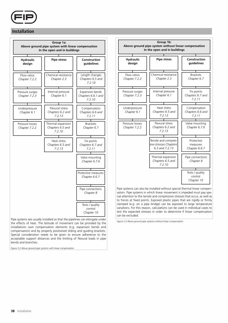
Installation
38 Installation
Pipe systems are usually installed so that the pipelines can elongate under
the effects of heat. The latitude of movement can be provided by the
installations own compensation elements (e.g. expansion bends and
compensators) and by properly positioned sliding and guiding brackets.
Special consideration needs to be given to ensure adherence to the
acceptable support distances and the limiting of flexural loads in pipe
bends and branches.
Figure 5.2 Above ground pipe systems with linear compensation
Pipe systems can also be installed without special thermal linear compen-
sation. Pipe systems in which linear movement is impeded must pay spe-
cial attention to the tensile and compressive stresses that occur, as well as
to forces at fixed points. Exposed plastic pipes that are rigidly or firmly
clamped (e.g. on a pipe bridge) can be exposed to large temperature
variations. For this reason, calculations can be used in individual cases to
test the expected stresses in order to determine if linear compensation
can be excluded.
Figure 5.3 Above ground pipe systems without linear compensation
Group 1a:
Above ground pipe system with linear compensation
In the open and in buildings
Hydraulic
design
Flow ratios
Chapter 7.2.2
Pressure surges
Chapter 7.2.3
Underpressure
Chapter 6.1
Pressure losses
Chapter 7.2.2
Construction
guidelines
Length changes
Chapters 6.5 and
7.2.10
Expansion bends
Chapters 6.6.1 and
7.2.10
Compensators
Chapters 6.6 and
7.2.11
Brackets
Chapter 6.7
Fix points
Chapters 6.7 and
7.2.11
Valve mounting
Chapter 6.7.6
Protective measures
Chapter 6.6.7
Pipe connections
Chapter 8
Pipe stress
Chemical resistance
Chapter 2.3
Internal pressure
Chapter 6.1
Flexural stress
Chapters 6.2 and
7.2.13
Thermal expansion
Chapters 6.5 and
7.2.10
Heat stress
Chapters 6.5 and
7.2.13
Tests / quality
control
Chapter 10
Group 1b:
Above ground pipe system without linear compensation
In the open and in buildings
Hydraulic
design
Flow ratios
Chapter 7.2.2
Pressure surges
Chapter 7.2.3
Underpressure
Chapter 6.1
Pressure losses
Chapter 7.2.2
Construction
guidelines
Brackets
Chapter 6.7
Fix points
Chapters 6.7 and
7.2.11
Compensators
Chapters 6.6 and
7.2.11
Valve mounting
Chapter 6.7.6
Protective
measures
Chapter 6.6.7
Pipe connections
Chapter 8
Tests / quality
control
Chapter 10
Pipe stress
Chemical resistance
Chapter 2.3
Internal pressure
Chapter 6.1
Heat stress
Chapters 6.5 and
7.2.13
Flexural stress
Chapters 6.2 and
7.2.13
Tensile and compres-
sive stresses Chapters
6.3 and 7.2.13
Thermal expansion
Chapters 6.5 and
7.2.10

39
Installation
Installation
Group 2:
Buried pipe systems
Hydraulic
design
Flow ratios
Chapter 7.2.2
Pressure surges
Chapter 7.2.3
Soil loads
Chapters 6.4.1 and
6.8
Traffic loads
Chapters 6.4.2 and
6.8
Ground water
effects
Chapter 6.4.3
Pressure losses
Chapter 7.2.2
Construction
guidelines
Trench form
Chapter 6.8
Fix points
Chapters 6.7 and
7.2.11
Bending radius
Chapter 6.8.2
Building
connections
Chapter 6.8.3
Pipe connections
Chapter 8
Tests / quality
control
Chapter 10
Pipe stress
Chemical resistance
Chapter 2.3
Internal pressure
Chapter 6.1
External overpressure
and internal under-
pressure Chapter 6.1
Heat stresses
Chapter 6.5
Thermal expansion
Chapters 6.5 and
7.2.10
Buried pipe systems are subject to other load characteristics than above
ground pipe systems. In designing pipelines, emphasis is placed on
determining the largest possible load capacity of the pipe under the
effects of external forces and the testing of stability.
Figure 5.4 Buried pipe systems
Group 3:
Concrete-encased pipe systems
Hydraulic
design
Flow ratios
Chapter 7.2.2
Pressure surges
Chapter 7.2.3
Buoyancy
Chapter 6.4
Dent resistance
Chapter 6.4.3
Pressure losses
Chapter 7.2.2
Constriction
guidelines
Brackets
Chapter 6.7
Expansion cushion
Chapter 6.9
Fix points
Chapters 6.7 and
7.2.11
Pipe connections
Chapter 8
Tests / quality
control
Chapter 10
Pipe stress
Chemical
resistance
Chapter 2.3
Internal pressure
Chapter 6.1
Heat stress
Chapters 6.5
Thermal expansion
Chapters 6.5 and
7.2.10
Pipe systems can also be installed so that an encasement in concrete walls,
decks, foundations, etc is possible after completion of the installation.
The concrete surrounding the pipe impedes length changes resulting
from temperature fluctuations (e.g. due to the temperature of the flow
medium or the effects of external temperature). Since no friction-type
connection exists between the plastic pipe and the concrete, measures
must be taken to protect individual pipe elements.
Figure 5.5 Concrete-encased pipe systems
External overpressure
and internal under-
pressure Chapter 6.1

Installation
40 Installation

41
Planning and construction guidelines and stress types
Planning and construction guidelines and stress types
6 Planning and construction guidelines andstress types
In principle, several internal and/or external stresses can affect a pipe sys-
tem. This especially applies to buried pipe systems. Potential types of
stress will be discussed below.
6.1 Internal and external pressure loads
In a pressure pipe system, principal stresses occur in various directions
under the effects of compressive loads (internal and external overpres-
sure, or internal underpressure). In principle, the below-listed types of
stress can be distinguished:
- Radial stress (�r)
- Axial stress, longitudinal stress (�a)
- Tangential stress, circumferential stress (�t)
Figure 6.1 Stresses as function of the direction of their effects
The size of the respective stress can be calculated using the equations in
chapter 7. The diagrams in appendix B are also aids for determining pres-
sure load capacity.
6.1.1 Internal overpressure
An overload of a pressure pipe system due to internal overpressure
results, especially in association with additional heat effects, to a conti-
nuous expansion of the pipe until it breaks.
The danger of an expansion arises as a result of too small wall thicknes-
ses, in which an indiscriminate wall thickness increase is not justifiable. In
the presence of heat expansion, a wall thickness enlargement also incre-
ases the reactive forces on the pipe fixed points. The engineer must
ensure that the wall thickness is designed to meet requirements while
the pipe remains elastic in response to any length changes that might
arise. A sudden change in structural operating conditions due to internal
pressure leads to pressure surges. The distinctive elasticity of the plastic
pipe has the advantage that the extreme values of pressure waves are
significantly lower than in steel pipes. Despite this fact, pipe systems ope-
rated by pumps or containing rapidly closing shut-off valves must be
tested for any foreseeable effects of pressure surges.
6.1.2 Internal underpressure and/or external overpressure
Thin-walled pipes can dent as a result of internal underpressure or exter-
nal overpressure, which is to say that they can lose their circular shape. To
guard against possible instability, the critical dent pressure of a pipe must
be calculated in relation to the standard dimension ratio. The critical dent
pressure (�crit) must display a safety factor SF = 2.0 against underpressure
(according to ATV A 127, a safety factor of 2.0 to 2.5 is to be incorpo-
rated). In professional literature, the denotation "N" is used to designate
the safety factor (SF).
6.2 Stress due to pipe deflection
Usually, deflection occurs in a pipe length as a result of the filled pipe's
dead weight, including the weights of valves. The flexural stress resulting
from a bend depends on the weight and span of the pipe between two
support points.
In establishing support distances (LD) in compliance with appendix B4,
the flexural stresses are so small that no overload or strain on the outer
surface can occur. It must be noted that support distances have to be
reduced when other components (e.g. valves) are present, or else additi-
onal support has to be provided. Especially notable are the significantly
higher flexural stresses created by deformation of pipe branches and
bends in connection with changes in direction.
Experienced has shown that, depending on the installation temperature
and the standard dimension ratio, the bending of pipe strings that might
predominantly occur in buried installations does not have any effect on
the service life and operational reliability of the pipe. Temperature loads
in a plastic pipe system affect strength values. Varying temperature loads
can produce heat stresses if pipe expansion is restricted or prevented.
Heat stresses are also created by temperature differences between the
inner and outer wall of the pipe.
The stresses created by constricted conditions (e.g. impeded thermal
expansion between two fixed points) are absorbed by the visco-elastic
behaviour of the plastic pipe until a tension/expansion equilibrium is cre-
ated. This process is also termed relaxation. Critical operating conditions
arise when varying loads are involved, and the periods of high tempera-
ture grow longer than the periods of low temperature. In particular, ten-
sile stresses with long-term effects can, after frequent load changes,
result in fatigue fractures. Stress peaks occur when an initial temperature
variation affects an installation condition. If the temperature level
remains nearly constant over a longer period, the heat stresses are redu-
ced by relaxation to level = 0.50% of the maximum value. Heat stress
generated by a varying thermal load and tensile stress having a long-term
relaxing effect can be calculated according to the equations in chapter 7.
Internal and external loads on pipe systems
Internal pressure
Internal
over-
pressure
Pipe bendingChemical
influences
Temperature
loads
External loads
(buried pipe sys-
tems)
Tensile and com-
pressive loads
Figure 6.2 Internal and external loads on pipe systems
Outer Inner
(e.g. flow medium)
Soil load
Traffic load
Ground water
Internal
under-
pressure
�r
�t
�a

Planning and construction guidelines and stress types
42 Planning and construction guidelines and stress types
6.3 Tensile and compressive loads
As a result of differing thermal expansions in the inner and outer wall of
a pipe, compressive stresses develop on the warmer side and tensile
stresses on the colder side. At the same time, these stresses interact with
the internal pressure. Stress values can be calculated using the equations
in chapter 7. Compressive and tensile stresses do not only arise in con-
nection with constricted thermal expansion but also due to the internal
pressure itself. In particular, length changes related to short-term stress
peaks can be observed in pressure tests involving increased internal pres-
sure. It should also be noted that the effects of notches in the pipe wall
are significantly strengthened by tensile loads.
6.4 Loads on buried pipe systems
6.4.1 Soil load
The bearing capacity of buried plastic pipes depends on the combined
effects of pipe and soil. The top of the pipe is pressed down under soil
load and the sides of the pipe are pushed out into the surrounding soil.
The reaction pressure that a lateral force exercises on the pipe causes a
large cross-section deformation (support effect). The form of the trench,
the nature of the pipe embedding and the backfill for the trench sub-
stantially determine the bearing capacity and stability of a buried plastic
pipe system. The load must be evenly spread over the entire pipe length.
It is also necessary to design pipe brackets that eliminate longitudinal
bending and point loading. The acceptable installation depth (i.e. the
bearable soil load (pE)) is calculated using the following equation:
Equation 6.1
pE = external soil pressure (kN/m2)
�B = specific weight of the soil (kN/m3)
(soil groups 1-3 -> �B = 20)
h = height of the soil layer above the top of the pipe
The acceptable installation depth (i.e. the bearable soil load) essentially
depends on:
- pipe wall thickness
- pipe and soil stiffness
- form of the trench
- pipe embedding and trench backfill
6.4.2 Traffic load
Pressure dispersals resulting from traffic loads due to road and rail trans-
port are assumed to be an evenly distributed surface load (p = surface
load). The soil stress (psoil) resulting from traffic loads is calculated in the
following equation:
Equation 6.2
psoil = soil stress (kN/m2) (acc. to ATV A 127, there designated "�")
aF = correction factor for road-traffic loads (-)
pF = soil stress resulting from traffic loads (kN/m2)
(acc. to ATV A 127)
The stresses derived from the above-indicated equation are multiplied by
a shock factor ( ), which takes the nature of traffic load into considera-
tion.
Generally, the following shock factors are employed:
1.2 for SLW 60
1.4 for SLW 30 road traffic
1.5 for SLW 12
Inserting the calculated stresses and corresponding shock factors in the
following equation 6.3 yields the actual effective traffic load.
Equation 6.3
psoil = soil stress (kN/m2) (acc. to ATV A 127)
= shock factor for road-traffic loads (-)
pv = soil stress resulting from traffic loads (kN/m2)
(acc. to ATV A 127)
For pipes under railways, the following applies:
= 1.4 - (0.1 . (H - 0. 5)) > 1
With burial depth > 4.00 m, general experience indicates that all stress
differences between dead soil load and percussive traffic load completely
disappear. With diminishing burial depths, the influence of the traffic
load above soil load grows larger. The minimum height of the soil layer
Hmin for railway traffic loads is:
Equation 6.4
Under certain conditions, a minimum soil layer Hmin < 1.50 m make it
necessary to invoke special measures (e.g. use of protective pipe). The
guidelines from Bahn AG are to be observed when manufacturing rail-
way crossings. The vertical aggregate stress on buried pipes is composed
of both soil and traffic loads. The horizontal stresses produced by traffic
load can be ignored.
6.4.3 Ground water
Buried pipes can be exposed to external overpressure (this especially
applies to areas with high ground-water tables). Similarly, a pipe encased
in concrete, if only for a short time, is subject to an external pressure. A
dent resistance test is required for buried pipe systems that are burdened
by additional external pressure.
The effects of the external pressure load correspond to the hydrostatic
pressure on the pipe axis.
Equation 6.5
pw = external water pressure (bar)
�w = specific weight of the fluid (for water = 1.00) (kN/m3)
hw = height of the water column above the top of the pipe
The critical dent pressure (pK) of a circular PE pipe as a result of water
pressure is:
Equation 6.6
ECR = creep modulus for the pipe material as a factor of temperature
and load period (N/mm2)
e = pipe wall thickness (mm)
de = outside diameter of the pipe (mm)
pk = critical dent pressure (bar)
� = transverse contraction value (for PE � = 0.38-0.40) (-)
The safety factor (SF > 2.0) usually used in the stability test (according to
ATV A 127, a security factor designated there as "N" of 2.0 to 2.5 is to
be taken into account) makes it necessary to undertake the following
verification:}

43
Planning and construction guidelines and stress types
Planning and construction guidelines and stress types
Equation 6.7
pw acc = acceptable external water pressure (bar)
p = critical dent pressure (bar)
SF = safety factor (-)
Note:
The soil surrounding a buried pipe has a supporting effect. It is therefore
possible to derive support factors that enable the critical and, conse-
quently, the acceptable external pressures to be increased. Technical lite-
rature provides the support factor values indicated in table 6.1.
Appendix B11 can be consulted to roughly estimate the external pressure
stability.
Example applying appendix B11
Invoking three examples, we can clarify the use of appendix B11 for
potential pressure loads created by external overpressure or internal
underpressure.
Case 1: External overpressure alone
Operating conditions:
Material: PE100, SDR 11
Operating temperature: 25°C
Internal underpressure (pu) 0 bar (no underpressure)
Result:
Maximum pressure load (pex tot) from external overpressure (pex) (maxi-
mum height of the water column (hw) above the top of the pipe) and no
underpressure (pu) in the pipe system:
Read from appendix B11:
pex tot = 1.0 bar à 10 mWs
-> pex tot = pex + pu
-> pex = pex tot - pu = 1.0 bar - 0 bar = 1.0 bar
à pex = pex tot = 1.0 bar
Case 2: Internal underpressure alone
Operating conditions:
Material: PE100, SDR 11
Operating temperature (TO1): 25°C
Operating temperature (TO2): 50°C
External over pressure (pex): 0 bar (no external overpressure)
Result:
Maximum pressure load (pex tot) from internal underpressure (pu) and
no outside overpressure (pex):
Read from appendix B11:
for TO1 = pex tot1 = 1.0 bar
for TO2 = pex tot2 = 0.6 bar
For TO1, the following holds:
-> pex tot1 = pex + pu
-> pu = pex tot1 - pex = 1.0 bar - 0 bar = 1.0 bar
-> p = pex tot1 = 1.0 bar
-> The selected pipe system is vacuum stable.
For TO2, the following holds:
-> pex tot2 = pex + pu
-> p = �ex tot2 - p = 0.5 bar - 0 bar = 0.5 bar
-> pu = p tot2 = 0.6 bar
-> patm = 1 bar ; pabs = patm - pu = 1 bar - 0.6 bar
= 0.4 bar absolute pressure
-> The selected pipe system is not vacuum stable under these
operatingconditions, as �u max = 0.6 bar!
Case 3: Internal underpressure and external overpressure
Operating conditions:
Material: PE100, SDR 11
Operating temperature (TO1): 25°C
Operating temperature (TO2): 50°C
Maximum water column above the top of the pipe = pex: 7 m
Maximum underpressure (pu) in pipe system: 0.2 bar
Result:
Maximum pressure load (pex tot) from external overpressure (pex) (maxi-
mum height of the water column (hw) above the top of the pipe) and
internal underpressure (pu) in the pipe system:
Read from appendix B11:
for TO1 = p tot1= 1.0 bar
for TO2 = p tot2= 0.6 bar
For TO1, the following holds:
-> p tot = pex + pu
-> pex tot = pex + pu = 0.7 bar + 0.2 bar = 0.9 bar
-> pex tot = pex tot 1
-> selected pipe is suitable!
For TO2 , the following holds:
-> pex tot = pex + pu
-> pex tot = pex + pu = 0.7 bar + 0.2 bar = 0.9 bar
-> pex = pex tot2
-> Since pex tot > pex tot2, the total pressure load for the pipe system
selected in the example is too large, which means that the selected
pipe is unsuitable for this load.
TO = operating temperature (°C)
TO1, TO2 = selected operating temperature (°C)
pex = external over pressure (bar)
pabs = absolute pressure (bar)
patm = atmospheric pressure 1 bar (bar)
pex max = maximum external overpressure (bar)
pu = internal underpressure (bar)
pu max = maximum internal underpressure (bar)
pex tot = pressure difference between external overpressure and
internal underpressure (bar)
pex tot1 = pressure load read from appendix B11 for tO1 (bar)
pex tot2 = pressure load read from appendix B11 for tO2 (bar)
hw = height of the water column above the top of the pipe (m)
6.4.4 Superposition of loads
According to appendix B11, the simultaneous effects of soil pressure and
external water pressure can reduce additional load values.
In practice, the superposition of several internal and external influences
can occur and have adverse effects on a pipe system. This means that,
besides external loads, internal loads arising from internal pressure and/
or impeded thermal expansion can affect the pipe system. In addition,
buoyancy in ground water can cause flexural stress along the pipe axis.
The multiplicity of superposed loads requires careful and extensive plan-
ning of buried plastic pipe systems.
6.4.5 Structural analysis
Buried pipe systems must be regarded as special cases on account of
their external loads.
They always require a differentiated analysis based on the installation
guideline ATV A127. Most equations and data on the preceding pages
Nominal pressure Support factors fsup (-)
(bar) with compaction without compaction
SDR 17 2.3 1
SDR 11 1.2 1
Table 6.1 Support factors for buried pipe systems
~~

Planning and construction guidelines and stress types
44 Planning and construction guidelines and stress types
are established on the basis of this ATV guideline. A generalisation of the
calculation methods is not possible due to the extent of the factors
involved, making it necessary to abandon any simple overview of the
equations.
6.5 Causes of length change
Plastic pipe systems are subject to discernible length changes even under
small temperature variations on account of their high thermal length
expansion coefficient (��). As a result, the pipe system is constantly in
motion in order to compensate for any temperature differences that
arise. Length changes and associated linear expansions in pressure pipe
systems mostly occur due to the superposition of several influential fac-
tors. The largest role in this regard is played by the additional occurrence
of internal pressure loads.
6.5.1 Length change due to internal pressure load
Consideration must be given to pressure tests on pipe systems in which
the test pressure can be 1.5 times larger than the nominal pressure. Test
and/or operating pressures create axial stresses in the pipe that can result
in longitudinal deformation on account of the low creep modulus of
thermoplastics. The actual length change will often turn out to be smal-
ler than the mathematically calculated one, since the expansion of the
pipe system is impeded by friction. This difference is, however, irrelevant
to the mathematical analysis of length changes and their effects.
6.5.2 Length change due to chemical effects
Besides the frequently mentioned good to very good resistance of polyo-
lefin to a large number of chemicals, there are cases when chemical
interaction is to be anticipated. In such cases, the appropriateness of the
pipe material should be tested on the expected chemicals to be transpor-
ted early in the planning stage. Various chemicals can cause length chan-
ges in pipe systems. Under certain circumstances, the chemicals being
used can instigate swelling of the pipe or fitting. In such cases, the pipe
wall absorbs more or less of the fluid contacting the pipe wall and conse-
quently increases in volume. This expansion occurs both in a horizontal
and in a radial direction to the pipe axis. The action of chemical com-
pounds can, under certain conditions, result in reactions that have a
detrimental effect on operating temperature. These temperature chan-
ges can subsequently produce thermal length changes that are unwan-
ted and harmful to the pipe system.
Figure 6.3 Variables that affect length change
6.5.3 Length change due to varying operating temperatures
In only considering the effects of operating temperature, it is possible to
detect that the condition of the pipe changes after initial use in accor-
dance with the operating temperature involved.
Decisive for the size of the length change is the temperature difference
(��) that comes into effect. It is therefore advisable to test the effects of
the length change at various operating temperatures at least once. After
initial operation, a check should be made to see if the shifting of indivi-
dual pipe lengths has damaged or might damage the pipe fixed points.
6.5.4 Length change due to ambient temperatures
Not only temperature differences of the medium but also outside tempe-
rature differences caused by changes between day and night as well as
summer and winder periods are partly associated with large length chan-
ges. In particular, empty pipe systems exposed to solar radiation or the
effects of frost must contain sufficiently designed compensation ele-
ments. The risk potential results from high flexural stresses in expansion
bends and large forces on clamp positions (pipe fixed points).
6.6 Compensation for length changes
Plastic pipe systems are generally installed so that a compensation device
absorbs any length change. There are also various design options, which
will be dealt with in the following chapters.
6.6.1 Elbows
Usually, the site-specific pipe layout can be segmented by a given fixed-
point design enabling length changes to be absorbed by pipe strings run-
ning at right angles to the direction of expansion.
This requires the smallest expenditure and the pipe system remains, in
itself, closed.
The compensation pipe lengths created by this installation method have
L, Z or U forms, or are geometrically interconnected with each other in
the indicated forms.
Consideration has to be given to the fact that length changes in one pipe
string lead to bends in others.
Since the resulting flexural stresses are transmitted to the expansion
bend, it is recommended that these do not exceed the minimum length
calculated in appendices B5 to B8.
The mathematical determination of expansion bends as compensation
for length changes will be discussed in detail in chapters 7.2.10.
6.6.2 Compensators
If linear compensation by means of expansion bends is not or only partly
possible, compensators must be incorporated in the system. These are
also required at connection points with smaller load capacities, such as
pump and tank supports.
In addition, compensators serve to reduce vibrations and their transmis-
sion to building structures. The design and construction of compensators
is based on operating pressure and temperature.
- Axial compensators
Axial compensators are predominantly used to absorb length changes
along the pipe axis. They can only absorb longitudinal forces by using
tension bars, but not any transverse forces.
- Lateral compensators
Lateral compensators serve to absorb movement in both axial and trans-
verse directions to the pipe axis. Since tension rods are involved in their
construction, they constitute a force-locking element in the axial direction.
- Angular compensators
Angular compensators are also called lateral expansion joints. They pro-
vide suitable compensation for large length changes in both level and
three-dimensional pipe systems. A length change is compensated in the
expansion joint by bending pipe sections.
Figure 6.4 Length change compensation
Variables that affect length change
Chemicals Varying
operating
temperatures
Ambient
temperatures
Internal
pressure
Compensation possibilities for length changes
Expansions bend Compensators Expansion couplers
Axial compensators Angular
compensators
Lateral
compensators

45
Planning and construction guidelines and stress types
Planning and construction guidelines and stress types
- Forces in pipe lengths with compensators
Each length change in pipe systems generates a resistance of which the
size is influenced by the nature of the compensation elements. The smal-
ler that this resistance is, the smaller the reaction forces are and the lar-
ger the length change (�l). The length change of the pipe causes the
compensator to be pressed together or deformed and exercises, as a
result, a reaction force.
The reaction force (= fixed point load) is composed of the deformation
resistance of the compensator and the longitudinal force produced by
the internal pressure, based on the effective cross-sectional area of the
compensator.
The possibility cannot be excluded that the load on the fixed point is
made larger by incorporating an compensator than it would be using
expansion bends. In planning fixed point constructions, special attention
should be paid to this fact.
- General remarks on compensators
The following rules need to be followed when making use of compensators:
- To function effectively, compensators must be mounted between
two fixed points.
- The distance from one guide bracket (guide saddle) should not be
any larger than 3x the pipe diameter.
- Only one compensator can be fitted between two fixed points.
6.6.3 Expansion couplers
Expansion couplers are suitable for absorbing axial length changes.
Moreover, expansion couplers are only to be used in pipe systems in
which no load produced by underpressure is to be expected (leakage in
the sealing part of the coupler). If abrasive media are being transported
(e.g. hydraulic transport of solids such as quartz sand water mixtures), FIP
will certainly not be allowed to employ expansion couplers. Details on
function, specifications and areas of application for expansion couplers
can be found in chapter 8. By arranging guide brackets (guide saddles) in
the immediate proximity of couplers, care needs to be taken to prevent
the pipe from kinking on the side. The expansion coupler is not longitudi-
nally force-locked and must also be installed between two fixed points.
The resulting load on fixed points is smaller than the fixed-point that
occur when compensators are used. A typical application for expansion
couplers involves linear compensation in a rigid connecting piece
between or more tanks.
6.7 Brackets
Brackets, also called pipe bearings, pipe saddles or pipe fixings, have the
task of safely transferring all the loads arising in an pipe system to the
building structure or infrastructure. Pre-requisite for the combined effects
of pipes and brackets is the functional construction and design of the
fixing elements. Examples of various arrangements of brackets in a pipe
system are presented in figure 7.13.
6.7.1 Sliding and hanging brackets
Sliding and hanging brackets (sliding and hanging bracket saddles) can
only absorb vertical forces and will only provide limited resistance to any
operating movement. In incorporating sliding and hanging brackets, care
must be taken that both longitudinal and a lateral movement of the pipe is
given some play. The nature of this type of fixing is extremely susceptible to
vibration, so their use in pipe systems powered by pumps is not recom-
mended or only permissible along with guide brackets (guide saddles).
6.7.2 Guide brackets
Guide brackets (guide saddles) have to prevent any lateral deflection of
the pipe. Due to their construction, they are therefore able to absorb
transverse forces. The incorporation of guide brackets ensures that a pipe
string cannot kink as a result of axial restraint.
6.7.3 Criteria for using brackets
The most important criteria for the correct application of brackets in a
plastic pipe system are:
- If possible, pipes should be equipped at the bracket points with
saddles. If there is no provision for the sliding of pipes in the saddles,
plastic or rubber inserts can be used. The pipe may, however, not be
crimped at the fixed point.
- If the pipe is to have the possibility of moving freely and uninhibitedly
in brackets (saddles), the inside diameter of the bracket must be larger
than the outside diameter of the pipe.
- Brackets may not be sharp-edged or linear. Point supports are also not
acceptable.
- Pipes with large diameters are frequently equipped with saddle shaped
supports. The angle of contact of the pipe must be at least 90°. At the
same time, it must ensure suitable lift protection.
- The expansion of the pipe string must not be impeded by the bracket
construction. The structure of the sliding surfaces must be corrosion
resistant and offer sufficient room for shifting. Under certain
circumstances, a final limit is provided.
- In a pipe installation without linear compensation (axially constricted),
the acceptable support intervals (LS) is, according to appendix B4,
comparable with the critical buckling length LK = LF (guide distance)
indicated in appendix B10.
The smallest value indicated in this comparison is to be used as the actual
value, which is Lact = Lx (with Lx < f (Ls, LK, LF). The acceptable fixing dis-
tance is:
Equation 6.8
This especially applies to pipes of small diameter.
- At positions in which the bracket distances must have very large
designs for structural reasons, additional or movable supports (e.g.
installation rails) must be provided. A support also serves to stabilise
small pipes and prevent larger flexural deflections in pipe systems
under constantly high operating temperatures. The support is
connected to the pipe by means of a strap. Care must also be taken to
ensure that , despite the additional supports, unimpeded sliding in
brackets and/or expansion couplings can occur.
- If heat expansion gives rise to the danger of the pipe being lifted off its
supports, or if vertically hanging brackets are attached to vertically
inclined pipe sections, the inclusion of additional spring elements can
be required (constant support).
- Sliding and hanging brackets (sliding and hanging bracket saddles) are
provided if movement might occur in any direction. The pipe
supported in this manner is however very susceptible to damage from
vibration and must have a few intermediate brackets for cushioning
effect.
- Concrete applications for sliding and hanging brackets (sliding and
hanging bracket saddles) occur as fixed points involving expansion
bends. Their design ensures that the acceptable support distances are
not exceeded even in cases of large expansion bends.
- Radial guide brackets (guide saddles) are predominantly used with
inclined pipes. They should be constructed In such a way that
movements along the pipe axis are possible while the pipe axis is
prevented from kinking. In addition, reaction forces due to vibrations
of the radial guide brackets can be dissipated.
6.7.4 Fixed points
Fixed points will prevent shifting or movement of the pipe in any direc-
tion. They also serve to absorb reaction forces (e.g. when compensators
or expansion couplers are used).
If a pipe system is constructed so that linear compensation cannot occur
(axially constricted), the fixed-point design must be given special atten-
tion. The mathematical calculation of loads on fixed points will be dis-
cussed in chapter 7.2.11.

Planning and construction guidelines and stress types
46 Planning and construction guidelines and stress types
6.7.5 Principles for the layout and construction of fixed points
- Fixed points are to be arranged so that direction changes in the pipe
route can be used to absorb length changes.
- They are also to be designed in considering all the loads that might
arise. In addition to reaction forces from friction at bracket contact
points and deformation of bends, large forces are produced by fixed
restraints of pipe lengths.
- The pipe must have the appropriate retainer rings to transfer the
forces to the construction of the fixed point. Insufficient consideration
of the restraint of the pipe in the bracket alone will, in many cases,
cause deformation of the pipe cross section or damage to the pipe
surface.
- Fixing pipe systems at fixed points should, if possible, be done at low
ambient temperatures, giving rise to predominantly compressive
stresses when heated (operating state).
- If flange connections occur in pipe lengths between fixed points,
tensile stresses can cause the joint pre-tension forces to decrease,
resulting in leakage at the flange connections.
- In inclining pipe segments, fixed points are employed to absorb dead
weight and dynamic loads. The design has to ensure that vertical
length changes do not produce any unacceptable tensile loads on the
horizontal connections.
6.7.6 Valve mounting
Locations in which valves or other heavy equipment encumber the pipe
system have to be provided with an additional support structure. Suppor-
ting valves not only serves to bear weight but also prevents the transfer
of large actuating forces to the pipe system.
The design features must be arranged to enable replacement of the val-
ves without simultaneous disassembly of the entire fixing. If the valve
mount corresponds to a fixed point, consideration must be given to the
consequences of the restricted length change.
6.7.7 Protective measures
Protective measures for above ground pipe systems outside buildings
(e.g. on pipe bridges) include insulation against loss of heat or cooling,
concomitant heating and UV light blinding. Protected pipes are no longer
exposed to extreme ambient temperatures that can result in such effects
as a reduction in length change. In establishing the bracket distances in
accordance with appendix A8 to A15, B4 and B10, it should be noted
that the dead weight of the insulation will cause increased deflection.
Protective measures can also be used to limit maximum pipe wall tempe-
ratures and therefore broaden the range of internal pressure loads for
which the pipes are suitable. DVS 2210 Part 1 provides the following
information on the UV stability of PE:
"Thermoplastic pipes treated with stabilising additives can be used in the
open without any lasting effects from ultraviolet radiation (UV rays). Des-
pite coating the thermoplastic with lightfast pigments, longer exposure
to intensive UV light can cause discolouration (bleaching of the original
colour). Reduced impact resistance is also not to be excluded."
6.8 Construction and installation of buried pipe systems (figure 6.5)
Following is based on German directions.
Figure 6.5 Design of the trench
The height of the soil layer over the pipe is:
Hmin (*) + Hmax = mathematical calculation for the individual case in
accordance with ATV guideline A 127.
(*) Note on Hmin:
The KRV installation guideline for "pressure pipes" recommends that, in
designing pipe trenches, all pipe elements are to be placed at a frost-free
depth. Depending on the climate zone, the minimum height of the soil
layer over the pipe must lie between 0.80 and 1.80 m. The standards for
trench design are EN 1610, DIN 4124 and DIN 19630.
Trench bottom - Area a
The form and consistency of the trench bottom affects the mechanical
properties of thermoplastic pipes. The already present or prepared bed
must consist of stone-free sand and be easy to compact using appropriate
equipment. The pipe must be laid so that a suitable supporting surface
with an angle of at least 90° is formed. The depth of the trench can be cal-
culated using equation 6.9, which is frequently employed in practice:
Equation 6.9
HTr = depth of the trench (mm)
DN = Nominal diameter of the pipe (mm)
Trench width
Compactable backfill
Heig
ht
of
soil
laye
r h
(min
80
0)
Angle of support > 90º
A = Pipe bed (in pipe zone)
100 mm for normal soil composition
150 mm on rocks or hard soils
B = Pipe zone with height of soil layer Ho
C= Backfill with a soil layer over the pipe zone that has a height of
at least 800 mm
(stone-free sand, compacted)

47
Planning and construction guidelines and stress types
Planning and construction guidelines and stress types
The above-cited equation 6.9 is given the same form in EN 1610. EN
1610 provides the following minimum values that, unless otherwise indi-
cated, should not be exceeded:
- normal soil composition -> 100 mm
- rocks or hard soils -> 150 mm
Pipe embedding - Area b
The fill for the embedding of pipe systems must be stone-free soil, sand
or similar material that must be capable of proper soil compaction. The
embedding procedure significantly determines the soil pressure and soil-
load distribution, as well as the formation of a stress-relieving, lateral soil
pressure on the pipe.
The height of the embedding layer over the pipe (Ho) is:
H0 = min. 150 mm over the top of the pipe and 100 mm over
connecting elements (as stated in EN 1610)
Backfill - Area c
The backfilling and compacting of the trench occurs in layers. Soil types
and materials that can result in settling at a later time may not be used to
backfill the trench (e.g. ash, slag, stones). The compression ratio of back-
fill material is measure in %Proctor (%Dpr). The use of heavy compacting
or compression equipment for soil compaction is not permitted when the
soil layer over the pipe is <1.0 m.
6.8.1 Construction principles
The design (i.e. the form of the trench), the backfill and the correspon-
ding compaction of materials have important effects on the service life of
plastic pipe systems.
The following construction principles should therefore be observed:
- The pipe trench is shaped so that all pipe parts are covered by the
prescribed soil layer.
- In laying plastic pipes on the prepared trench bottom and in
subsequently embedding them, stones must be prevented from
contacting the plastic pipe (danger of notching that leads to cracking).
- In rocky or stony subsoil, the trench bottom is to be excavated 0.15 m
deeper and the additional excavation filled by a stone-free support
layer.
- Sand and fine gravel (grit size <20 mm) are the most suitable materials
for embedding pipes and compacting the pipe zone.
- All soil types occurring in nature are classified in DIN 18196 "Soil
classification for construction purposes and methods of recognising
soil groups". Soils are divided into:
Group 1: non-cohesive coarse soils (sandy, gritty soils)
Group 2: cohesive, fine soils (coarse clay, clay)
Group 3: cohesive, fine and coarse mixed soils
(cohesive sandy soils, gritty soils, cohesive stony weathered
soils).
- The compactability of individual soils and, consequently, the quality of
the compaction depend on the granulometric composition, the grain
shape and water content. The method of compaction with regard to
the equipment used is shown in table 6.2.
- Concrete or clay bar must, in certain circumstances, be incorporated in
slopes in order to prevent the sandy pipe bed from being washed
away. In some cases, drainage must be provided.
- In the case of bearing capacity changes of the trench bottom due to
differing soil layers, a sufficiently long fine-gravel or sand fill is applied
at the transitions.
The following instructions sheets are important for pipe trench design:
- DIN 4124 "Excavations and trenches"
- DIN 19630 "Guidelines for the construction of water pipes: DVGW
Technical Regulations"
- EN 1610 "Laying and testing drainage pipes and canals: Dutch
Version EN 1610:1997"
Type of equipment Soil group
Service weight
(kg)
I
Coarse (non-cohesive)
II
Fine (cohesive)
III
Mixed grained (cohesive)
Appro-
priate
Layer
height
Number Appro-
priate
Layer
height
Number Appro-
priate
Layer
height
Number
(cm) Trans. (cm) Trans. (cm) Trans.
1. Light compacting equipment (predominantly for the pipe zone)
Tamper light < 25 + < 15 2 - 4 + < 10 2 - 4 + < 15 2 - 4
Frogrammer medium
light
25 - 60
< 100
+
o
20 - 40
20 - 30
2 - 4
3 - 4
+
+
10 - 30
20 - 30
2 - 4
3 - 5
+
+
15 - 30
15 - 25
3 - 4
3 - 5
Vibrating plate light < 100 + < 20 3 - 5 - - - o < 15 4 - 6
Vibrating roller medium
light
100 - 300
< 600
+
+
20 - 30
20 - 30
3 - 5
4 - 6
-
-
-
-
-
-
o
o
15 - 25
15 - 25
4 - 6
5 - 6
2. Medium and heavy compacting equipment (above the pipe zone)
Tamper medium
heavy
25 - 60
60 - 200
+
+
20 - 40
40 - 50
2 - 4
2 - 4
+
+
10 - 30
20 - 30
2 - 4
2 - 4
+
+
15 - 30
20 - 40
2 - 4
2 - 4
Frogrammer medium 100 - 500 o 20 - 40 3 - 4 + 20 - 30 3 - 5 + 25 - 35 3 - 4
Vibrating plate heavy
medium
500
300 - 750
o
+
30 - 50
30 - 50
3 - 4
3 - 5
+
-
30 - 40
-
3 - 5
-
+
o
30 - 50
20 - 40
3 - 4
3 - 5
Vibrating roller heavy 750
600 - 8000
+
+
40 - 70
20 - 50
3 - 5
4 - 6
-
-
-
-
-
-
o
+
30 - 50
20 - 40
3 - 5
5 - 6
+ = recommended o = most suitable
Table 6.2 Type of compaction
* The above-stated data represents average performance data. In unfavourable conditions (e.g. high water content, sheet lining, the indicated layer heights
have to be decreased, while they can be increased in especially favourable conditions. Precise values are only ascertained by means of trial compaction. If no
trial compaction is run (except in cases involving steel and ductile iron pipes), only use the highest values for the layer heights indicated in the table.

Planning and construction guidelines and stress types
48 Planning and construction guidelines and stress types
6.8.2 Bending radius
Route direction changes can be followed by bending the pipe.
To avoid the risk of buckling and overstraining the outside surface, it is
recommended that the minimum bending radius not be exceeded (table
6.3).
Note to table 6.3:
The safety factor (SF) for the indicated SDR and ISO-S values of PE is 1.6.
The bending radius at an installation temperature of 20°C were mathe-
matically calculated. To calculate the bending radius at an installation tem-
perature of 0°C, the mathematically calculated values for an installation
temperature of 20°C were multiplied by a factor of 2.5. The bending
radius at an installation temperature of 10°C were interpolated (mean
values).
6.8.3 Building connections
When buried pipes connect to buildings, the possibility of settling has to
be taken into account. The elastic plastic pipe, due to the deformation
capacity zone (figure 6.6) over the length DZ (elbow length) ensures that
no overload can occur in the area of settlement.
6.9 Principles of constructing and installing concrete-encased pipe systems
Plastic pipes encased in concrete after installation represent a special case.
Their handling in connection with the technical application guidelines in
for pressure pipes in this manual is therefore limited to important or critical
details. The instructions may be applied to other similar circumstances.
Figure 6.6 Expansion zones in pipe bends
6.9.1 Behaviour of pipe systems under temperature loads
Once a pipe system is encased in concrete, no movement can any longer
occur. A pipe system without linear compensation is created, meaning that
increased heat stresses have to be taken into account. Since no friction-lock
connection is formed between the straight pipe and surrounding concrete,
the fittings constitute fixed points and are correspondingly subjected to
stress. In installing pipe systems, measures need to be taken to limit the
load on the fittings. Examples of such practices are described below.
6.9.2 Load on pipe bend
If extreme temperature differences can arise, pipe bends have to be pro-
tected against overstress. For this purpose, an expansion zone using
deformable material is incorporated. The chosen thickness of the expan-
sion cushions must be at least as large as �l. The length of the expansion
zone corresponds to the dimensions of the expansion bends in appendi-
ces B5 to B8.
6.9.3 Load on tee
Due to varying temperatures, fittings are subject to surface pressure. This
adverse load concentrates on tee sections, as additional shear forces are
created at outgoing connections.
If a load limiting element is placed directly beside the fitting, an electro-
fusion coupler is the most suitable connection piece. The longitudinal
force (force on a fixed point) (FFp) remains equally large, but the defor-
mation due to the significantly smaller �l is clearly less. Another option
for protection against overloading is the incorporation of an expansion
zone (expansion cushion).
6.9.4 Fixing pipe systems
In comparison with brackets, the installation of a concrete-encased pipe
system does not require any special measures. The fixing during installa-
tion only serves as float protection and is to be regarded as provisional
attachment prior to encasement with concrete.
Figure 6.7 Shear and fixed-point forces on tees and 45° branches
Material Bending radius at various installation temperatures
ISO-S SDR 0°C 10°C 20°C
PE100 8 17 50 x de 35 x de 20 x de
5 11 50 x de 35 x de 20 x de
Table 6.3 Bending radius

49
Planning and construction guidelines and stress types
Planning and construction guidelines and stress types
6.10 Chapter summary
Internal pressure loads Internal pressure loads create stresses in various directions. Radial stresses, axial stresses and tangential stresses
can occur.
Internal overpressure Internal overpressure can result in pipe expansion, especially under the effects of heat. Sudden changes in ope-
ration conditions can cause pressure surges.
Internal underpressure / external
overpressure
Exposed to internal underpressure or external overpressure, a pipe will tend to buckle, which means it deviates
for its ideal form (circular cross section). The critical buckle pressure should be calculated with regard to stability.
Pipe bending Pipe bending is usually caused by the dead weight of the pipe and/or additionally incorporated valves and pipe
fill. The relevant bracket distances (support distances) must therefore be determined and the suitable pipe brac-
kets incorporated.
Temperature loads Temperature loads have a very large effect on the mechanical properties of plastic pipe. Attention is first of all
to be paid to the relatively large thermal length change.
Tensile and compressive stresses on
the pipe wall
They are created during pipe manufacture due to differing cooling conditions. Compressive stresses arise in the
outer wall of the pie (usually the first surface to cool) and tensile stresses on the warmer inner wall of the pipe.
Soil load The soil layer on top of the pipe loads weight on the pipe and can cause it to deform. This load therefore has a
significant effect on the pipe structure and the service life of the pipe.
Trench form, pipe embedding and
backfill
Pipe trench design substantially influences the bearing capacity and stability of a pipe system, and therefore has
a large influence on the service life of the system.
Traffic loads Traffic loads are additional external loads that can affect the pipe system. They require special protective measu-
res. If the prescribed minimum soil layer over the pipe is not maintained, protective pipes may have to be instal-
led.
Railway traffic loads
(railway crossings)
The installation guidelines from ProRAil are important for installation under railways and railway facilities as well
as for railway crossings.
Ground water Areas having a high ground water table can load external overpressure on the pipe system. The same holds true
for concrete-encased pipe systems, which are exposed to short-term heightened overpressures. Both cases
require the calculation of dent resistance.
Length change The length change of a pipe system is caused by varying operating temperatures, varying ambient temperatures
or internal pressure loads. Frequently, several of these influences are superposed.
Compensation for length changes The inclusion of elbows, expansion couplers or compensators can compensate for length changes.
Elbow Elbows (expansion bends) absorb length changes by moving laterally perpendicular to the expansion direction.
Depending on structural and spatial conditions, they can be U, L or Z shaped.
Compensators Compensators are used if other compensation options cannot or can only be partially applied. The design
depends on operating pressure and temperature. Axial, lateral and angular compensators are used.
Expansion couplers Expansion couplers are predominantly employed in pressureless systems as connection elements and compen-
sation for length changes.
Brackets Brackets have the task of transferring the effective loads on the pipe system to the building structure or infra-
structure.
Sliding and hanging brackets
(sliding and hanging bracket sleeves)
They are only able to absorb vertical forces.
Guide brackets (Guide saddles) They serve to absorb both vertical and horizontal forces.
Fixed points Fixed points in association with suitable bracket concepts prevent shifting or movement of pipe systems.
Valve fixing Valve fixings not only serve as support for valves but prevent the transfer of reaction forces.
Protective measures for above
ground pipe systems
They are used to improve the insulation properties of pipe systems. The use of concomitant heating is necessary
in many cases. Protective measure may also be taken against UV radiation.
Bending radius In bending pipe, certain bending radius should not be exceeded (table 6.3).
Building connections Connections of building can be exposed to settling, which can be compensated by creating deformable zones.
Concrete-encased pipe systems Concrete-encased pipe systems function as a fixed restraint. Fittings behave in concrete as fixed points and are
therefore also subject to the same stresses, which means that any heat stresses must be absorbed and compen-
sated for in the pipe system.

Planning and construction guidelines and stress types
50 Planning and construction guidelines and stress types

51
Basic calculations
Basic calculations
7 Basic calculations
7.1 Factors influencing pipe system design
The listed data is meant to guide compilation of important data and vari-
ables important for the construction of a pipe installation.
Note:
The listed mathematical operations and relations have been simplified as
much as possible. Plastic-specific parameters and generally valid factors
are partly already integrated into calculation formulae. We have
abstained from detailing the derivation or reproduction of single values
to abbreviate this section.
7.2 Calculating pipe parameters
7.2.1 Explanation
The calculation of thermoplastic pipe systems is especially important for
the engineer undertaking a project. This chapter presents the basic prin-
ciples required for designing plastic pipe systems. However, the practitio-
ner (user) should also be able to acquire the necessary data and standard
variables for internally pressure-loaded pipe in a relatively simple manner
without spending a lot of time. The mathematical operations are suppor-
ted by diagrams in the appendices from which most values and data can
be read off. Thermoplastic pipe calculations basically occur on the basis
of long-term values. The reference stress (�ref) and mechanical (creep)
strength (i.e. creep modulus (EcR)) of a pipe system in relation to tempe-
rature can be derived from the creep diagram in appendix A1 and the
creep modulus curve diagram in appendix A2. The creep rupture curves
are based on internal pressure tests on pipe samples filled with water and
represent minimum values. If pipe systems are not intended for water but
for other flow media, their effects on creep strength properties must be
given special consideration.
Type of influence Short symbol Unit
Outside diameter de mm
Inside diameter di mm
Internal pressure pi bar
External pressure pex bar
Underpressure pu bar
Reference stress �ref N/mm2
Creep modulus EcR N/mm2
Operating temperatures
Lowest operating temperature
Highest operating temperature
Highest ambient temperature
Average installation temperature
Ti min
Ti max
Ta max
Tins
°C
°C
°C
°C
Safety factor
for load class I = 1.3
for load class II = 1.8
for load class III = 2.0
for stability N = 2.0
S
S
S
S
Calculated pipe wall temperature
TW = 0,9 . TFlow medium TW min
TW max
°C
Maximum occurring
temperature difference
max ���= Tu - Ti
T0 = upper maximum value
Tu = lower maximum value
�� K
Load period:
Load h/a (= hours per annum)
for min Tw
for max Tw
for �i
for �a
-
-
-
-
h/a
h/a
h/a
h/a
Calculated service life for
calculation of creep strength
tSL
tSL
h
a
Reduction factors
Time dependence (if applying
appendix A1, this factor has already been
taken into account)
A1 -
Reduction factor
(influence of ambient medium)
according to DVS 2205 - Part 1
A2 -
Reduction factor
Temperature dependence (if applying appen-
dix A1, this factor has already been taken
into account!)
A3 -
Reduction factor
(influence of specific resilience)
DVS 2205 - Part 1 (See table 7.12)
A4 -
Flow medium
Pressure loss per m pipe �p bar/m
Flow velocity w m/s
Flow volume V m3/h
Pressure Surge psurge
Welding factors
Short-term welding factor
Long-term welding factor
(The abbreviations fs and fl indicated here
have been freely chosen by FIP. In the DVS
2205 Part 1 guideline they are shown as fz
(short-term welding factor) and fl (long-term
welding factor)!
fsfl
-
-
Connection method
- detachable connection
- unions
- couplings
- plug-in connections
- flange connections
- compression connections
- permanently attached connections
- welding
o electrofusion
o butt-welding
o hot gas extrusion welding
o hot gas hand welding
o hot gas speed welding
EF
BW
HE
HW
HR
Types of installation
- above ground with linear compensation
- above ground without linear compensation
- concrete encased
- buried
- installation in the open
- installation in buildings
Additional influences
Type of influence Short symbol Unit
Table 7.1
.

Basic calculations
52 Basic calculations
7.2.2 Hydraulic principles
- Calculating flow velocity
Equation 7.1
di = inside diameter -> ds = de - 2 · e (mm)
V' = flow volume (flow rate) (m3/h)
V'' = flow volume (flow rate) (l/s)
w = flow velocity (m/s)
Standard values for fluids:
w 0.5 - 1.0 m/s -> intake side
w 1.0 - 3.0 m/s -> pressure side
- Calculating the flow volume
The required pipe size is derived from the flow velocity of the medium
and the clear cross-section of the pipe. The flow rate of fluids is calcula-
ted as follows:
Equation 7.2
di = inside diameter of the pipe (mm)
de = outside diameter of the pipe (mm)
e = pipe wall thickness (mm)
A = cross-sectional area of flow channel (mm2)
w = flow velocity (m/s)
V = flow volume (m3/h, l/s)
- Calculating the inside diameter of the pipe
If the flow rate (flow volume) is known and the constants in the above-
stated equations have been compiled, this yields a conventionally-sued
formula for calculating the inside diameter of the pipe:
Equation 7.3
di = inside diameter of the pipe (mm)
w = flow velocity (m/s)
V' = flow volume (m3/h)
V''= flow volume (l/s)
The tomogram presented in the appendix A16 (along with the associated
tables A16a, A16b and A16c) can be used to directly calculate the appro-
priate dimensions.
- Calculating the Reynolds number (Re)
The Reynolds number (Re) indicates the relationship of the inert forces
affecting the flow particles to the forces of viscosity. The Reynolds num-
ber is dimensionless and is calculated as follows:
Equation 7.4
Re = Reynolds number (-)
� = kinematic viscosity (m2/s)
w = flow velocity (m/s)
di = inside diameter of the pipe (mm)
- Determining the pipe friction number (P)
The dimensionless pipe friction number (P) is required to calculate the
hydraulic loss in the pipe. For laminar flows (Re < 2320) in circular cross-
sections, the following holds:
Equation 7.5
Re = Reynolds number (-)
P = pipe friction number (-)
In most cases, turbulent flows are created in pipes (Re > 2320).
The pipe friction number (P) for turbulent flows can be determined with
the aid of appendix A3. The pipe roughness value (k), which is crucial for
the calculation, can be considered to be 0.01. In practice, P = 0.02 can
be used to make rough estimates of hydraulic loss.
- Equivalent pipe length
Equation 7.6
Equation 7.7
Ltot = total pipe length (m)
�LPipe = sum of all pipe lengths in the system (m)
�LFitting = sum of all fitting lengths in the system (m)
�LValve = sum of all valve lengths in the system (m)
di = inside diameter of the pipe (mm)
P = pipe friction number (-)
��F = sum of the individual resistances of fittings (-)
��A = sum of the individual resistances of valves (-)
An exact indication of pressure loss at connections (welding joints, flange
connections, unions) is not possible because the nature and manner of
the connections vary. An overall addition of 10% to the calculated total
loss would appear to be appropriate.
- Calculating total pressure loss
In calculating the total pressure loss, the sum of the respective individual
pressure losses must be computed. The sum of the individual pressure
losses is calculated by:
Equation 7.8
��ptot = sum of the individual losses (bar)
��pRP = sum of the pressure losses in straight pipe lengths (bar)
��pRF = sum of the pressure losses in fittings (bar)
��pRV = sum of the pressure losses in valves (bar)
��pRC = sum of the pressure losses in connections (bar)
~~~~
.
.
.
.
.

53
Basic calculations
Basic calculations
- Pressure loss in straight pipe sections
The pressure loss in straight pipe sections is calculated using the follo-
wing equation:
Equation 7.9
��RP = pressure loss in individual pipe sections (bar)
R = pipe friction number (-)
LP = length of the pipe sections (m)
di = inside diameter of the pipe (mm)
�F = density of the flow (kg/m3)
w = flow velocity (m/s)
- Pressure loss in pipe fittings
Given that substantial losses result from friction, changes of direction and
transfer loss, these individual losses represent a significant portion of the
total pressure loss in a pipe system. The pressure loss is calculated with
the following formula:
Equation 7.10
��RF = pressure loss in individual pipe fittings (bar)
�F = density of the flow (kg/m3)
w = flow velocity (m/s)
�RF = resistance factors for pipe fittings (-)
The resistance factors for fittings will be identified in tables 7.2 to 7.7.
- Pressure loss in pipe connections
Pressure loss also occurs in pipe connections, although it cannot be preci-
sely characterised, as the geometric dimensions vary a great deal (e.g.
welding beads). DVS 2210 Part 1 recommends basing pressure loss calcu-
lations for connections in plastic pipe systems (such as butt, sleeve and
flange joints) on a resistance factor of �RF = 0.1 (-) . For pressures losses
in connections, this means:
Equation 7.11
��RC = pressure loss in connections (bar)
�F = density of the flow (kg/m3)
w = flow velocity (m/s)
�RC = resistance factor for pipe connections = 0.1 (-)
To obtain a rough estimate of the pressure loss in connections, it is suffi-
cient to consider an addition of 15% to the pressure loss in straight secti-
ons �P and fittings �PF.
- Pressure loss in valves
The pressure loss in valves can be determined using the following equation:
Equation 7.12
�pRV = pressure loss in valves (bar)
�F = density of the flow (kg/m3)
w = flow velocity (m/s)
�RA = resistance factors for pipe valves (-)
The resistance factors for valves are shown in table 7.10.
- Resistance factors
The pressure loss in a pipe system is caused by friction, changes of direc-
tion and transfer loss. To determine the variables involving total pressure
loss in a pipe system requires knowledge of the resistance factors (�F) for
fittings, pipe connections and valves. The most important resistance fac-
tors are indicated below.
- �F - values for seamless pipe bends
Figure 7.1 Seamless pipe bends
- �F values for segmented pipe bends
Figure 7.2 Segmented pipe bends
R/di
�
1 1.5 2 4
30° 0.23 0.19 0.14 0.11
45° 0.34 0.27 0.20 0.15
60° 0.41 0.33 0.24 0.19
90° 0.51 0.41 0.34 0.23
R/di
�
1.5 3 4 6
30° 0.10 0.10 0.11 0.11
45° 0.14 0.15 0.16 0.17
60° 0.19 0.20 0.22 0.23
90° 0.24 0.26 0.28 0.29
Table 7.2 �F value for seamless bends
Table 7.3 �F values for segmented pipe bends

Basic calculations
54 Basic calculations
- �F values for segmented pipe bends
Figure 7.3 Elbows
- �F values for tee sections
Figure 7.4 Tee for dividing and uniting flows
Vt -> total flow volume (l/s - m3/h)
Vc -> total continuous volume (l/s - m3/h)
Vo -> outgoing volume (l/s - m3/h)
Vi -> incoming volume (l/s - m3/h)
Positive values indicate pressure loss, negative values pressure increases.
- �F values for tanks and tank outlets
overlying -> �F = 2.0
flush -> �F = 0.3
rounded -> �F = 0.05
- �F values for cross-section changes
a) Pipe enlargement, perpendicular
b) Pipe constriction, perpendicular
c) Pipe enlargement, conical � value for P = 0.025
�E is the angle of enlargement. The � values are related to velocity (w2).
The conical length (l) is derived from the angle of enlargement (�E) and
the diameter ratio de2/de1. The best angle of enlargement in which the
stream of the inflowing medium still does not lose contact with the pipe
is about 7 to 8°.
Figure 7.5 Conical enlargement of the flow cross section
d) Pipe enlargement, conical � value for P = 0.025
Figure 7.6 Conical enlargement of the flow cross section
� 10° 15° 20° 30° 45°
�F 0.04 0.05 0.05 0.14 0.30
Vi/Vt Uniting flows
Vt=Vo+Vi
Vo/Vt Dividing flows
Vt=Vo+Vc
�z �d �a �s
0.0 -1.20 0.06 0.0 0.97 0.10
0.2 -0.40 0.20 0.2 0.90 -0.10
0.4 0.10 0.30 0.4 0.90 -0.05
0.6 0.50 0.40 0.6 0.97 0.10
0.8 0.70 0.50 0.8 1.10 0.20
1.0 0.90 0.60 1.0 1.30 0.35
de1 / de2 1.2 1.4 1.6 1.8 2.0
�F 0.07 0.15 0.24 0.46 0.56
de1 / de2 1.2 1.4 1.6 1.8 2.0
�F 0.10 0.22 0.29 0.33 0.35
�F values for angle of enlargement �E
de2/de1 4 - 8° 16° 24°
1.2 0.10 0.15 0.20
1.4 0.20 0.30 0.50
1.6 0.50 0.80 1.50
1.8 1.20 1.80 3.00
2.0 1.90 3.10 5.30
�F values for angle of enlargement �E
de2/de1 4° 8° 24°
1.2 0.046 0.023 0.210
1.4 0.067 0.033 0.013
1.6 0.076 0.038 0.015
1.8 0.031 0.041 0.016
2.0 0.034 0.042 0.017
Table 7.5 �F values for tees
Table 7.6 Pipe enlargement, perpendicular
Table 7.7 Pipe enlargement, perpendicular
Table 7.8 Pipe enlargement, conical
Table 7.9 Pipe enlargement, conical
.
.
.
.
tc
i
t c
o
. .
. . .. .
. ..
Table 7.4 �F values for segmented pipe bends

55
Basic calculations
Basic calculations
- �V values for valves
- � values for compensators
Surge suppressors : � = 2.0 per surge
Expansion joints : � = 3.0
- � values for welding seams
Electrofusion : � = 0.05
Butt-welding : � = 0.1
- � values for pipe bends in succession
180° bends : � = 2.0 · � 90°
Stage of 2 x 90° bends : � = 2.5 · � 90°
Expansion stage of 2 x 90° bends : � = 3.0 · � 90°
7.2.3 Investigating pressure surges
The change in the stationary conditions of a pipe system (e.g. due to acti-
vation of a butterfly valve or the failure of a pump) creates a pressure
wave producing superpositions due to reflections in bends, reducers, etc.
that can amount to many times the operating pressure. The largest pres-
sure increase occurs when the closure procedure or stop command follo-
wing pump failure falls under the so-called reflection time. If a pipe
system contains externally controlled valves or trip mechanisms, it must
be ensured that their closure time is larger than the reflection time.
If a pressure surge occurs, its effects must be investigated by means of a
short-term stress analysis and a stability test.
Note:
The pressure surge is not always sufficiently expressed by the following
equations. In particular, more precise investigations must be employed in
longer or complexly branched pipe systems in order to consider and eva-
luate all the significant factors.
Significant factors are:
Operating pressure, pump pressure = pO (bar)
Flow velocity = wo (m/s)
E modulus of the pipe material = EcR (N/mm2)
(short-term E modulus = creep modulus between 1 and 10 min)
E modulus of the flow medium = EF (N/mm2)
(for water at 20°C -> EF 2100 N/mm2)
Density of the flow medium = �F (g/cm3)
- Calculating pressure wave velocity (a)
Equation 7.13
The indicated resistance factors are reference values and are used in
rough pressure loss calculations. Object related calculations are based on
the data of the respected valve manufacturers.
Equation 7.14
Equation 7.15
a = pressure wave velocity (m/s)
a0 = speed of sound (m/s)
de = outside diameter of the pipe (mm)
di = inside diameter of the pipe (mm)
� = correction factor (-)
EcR = creep modulus of the pipe material (N/mm2)
EF = E modulus of the flow medium (N/mm2)
�F = density of the flow medium (kg/m3)
- Maximum pressure surge for �w = w0
Equation 7.16
a = pressure wave velocity (m/s)
pSurge = pressure surge (bar)
pO = pump pressure, operating pressure (bar)
�w = w0 - w1 (with w1 = flow velocity at the reflection position) (m/s)
For short pipes of a single length can be assumed that a surge degrada-
tion occurs.
Equation 7.17
ts = closing time of the butterfly valve or delay of the pump stop
command after failure (c)
LPipe = pipe length (m)
a = pressure wave velocity (m/s)
The surge degradation factor is:
Equation 7.18
Zs = surge degradation factor (-)
LPipe = pipe length between valve mechanism or pump and
reflection position (m)
ts = closing time of the butterfly valve or delay for the pump stop
command after failure (c)
a = pressure wave velocity (m/s)
Resistance factor (�)
25 4.0 2.1 3.0 0.1...0.3 0.1...0.15 0.3...0.6 2,5 1,9
32 4.2 2.2 3.0 0.1...0.3 0.1...0.15 0.3...0.6 2.4 1.6
40 4.4 2.3 3.0 0.1...0.3 0.1...0.15 0.3...0.6 2.3 1.5
50 4.5 2.3 2.9 0.1...0.3 0.1...0.15 0.3...0.6 2.0 1.4
65 4.7 2.4 2.9 0.1...0.3 0.1...0.15 0.3...0.6 2.0 1.4
80 4.8 2.5 2.8 0.1...0.3 0.1...0.15 0.3...0.6 2.0 1.3
100 4.8 2.4 2.7 0.1...0.3 0.1...0.15 0.3...0.6 1.6 1.2
125 4.5 2.3 2.3 0.1...0.3 0.1...0.15 0.3...0.6 1.6 1.0
150 4.1 2.1 2.0 0.1...0.3 0.1...0.15 0.3...0.6 2.0 0.9
200 3.6 2.0 2.4 0.1...0.3 0.1...0.15 0.3...0.6 2.5 0.8
Table 7.10 �-values for valves
incl
ine
d s
ea
t v
alv
e
dia
ph
rag
m v
alv
e
fla
t-se
at
va
lve
ball v
alv
e
ba
ll v
alv
e
bu
tte
rfly
va
lve
che
ck v
alv
e
free
-flo
w c
he
ck v
alv
e
no
min
al d
iam
ete
r D
N
~ ~
va
lve
wit
ho
ut
con
stri
ctio
n

Basic calculations
56 Basic calculations
The complete pressure change (��) corresponding to the velocity change
(�w) velocity when the closing time (tc) is smaller than the reflection time
(tR). The reflection time (tR) is calculated by:
Equation 7.19
tR = reflection time (c)
LPipe = pipe length between valve mechanism or pump and reflection
position (m)
a = pressure wave velocity (m/s)
The rough estimate of a pressure surge hazard can draw on the following
rule of thumb:
Equation
Equation 7.20
HP = delivery height of the pump (m)
Ks = pressure wave size (-)
LPipe = pipe length between valve mechanism or pump and reflection
position (m)
wo = flow velocity (m/s)
For Ks > 70 and with simultaneous use of rapidly closing valves, a special
pressure surge calculation is recommended.
- Calculating the pressure surge for the section involved
LPipe < 500 · de
Equation 7.21 is an empirical calculation formula. It should therefore only
be used when rough estimates are to be made for simple pipe systems
without fittings.
Equation 7.21
pSurge = pressure surge (bar)
p = pump pressure, operating pressure (bar)
w = flow velocity (m/s)
�F = density of the flow medium (g/cm3)
= surge factor (-)
In general, the following values can be selected for :
= 25 for rapidly closing valves
= 50 for normally closing valves
= 75 for slowly closing valves
The loads often arising along with pressure surges due to vacuums can,
under certain conditions, cause buckling of the pipe in specific situations.
The stability (i.e. buckling resistance) of the pipe series in question must
be verified in every case.
Equation 7.22
pCrit =critical underpressure (bar)
EcR = elasticity modulus (between 1…10 min) (N/mm2), see appendix A2.
e = pipe wall thickness (mm)
di = inside diameter of the pipe (mm)
From this, it follows:
Equation 7.23
pu = under pressure from pressure surge calculation (bar)
pCrit = critical underpressure (bar)
SF = safety factor (-)
Note:
Appendices B9 to B10 indicate the acceptable external pressure load (pex)
or the underpressure load (pu) in short-term observations (t = 100 h) and
long-term observations (t = 25a) for PE at various SDR levels.
7.2.4 Calculating acceptable stress
Calculation of acceptable stress requires the inclusion of various reduc-
tion factors. The significance of individual reduction factors will be dis-
cussed in section 7.2.6. The acceptable stress is determined by the
following formula.
Equation 7.24
�acc = acceptable stress (N/mm2)
�ref = reference stress (N/mm2), see appendix A2.
fl = long-term welding factor (-)
fs = short-term welding factor (max. 1h) (-)
R2 = reduction factor for the influence of the flow medium
(see table 2.3) (-)
R4 = reduction factor for the influence of the specific resilience of the
material (-)
SF = safety factor for the respective loads (see table 7.13) (-)
7.2.5 Welding factors
The size of the welding factors depends on the specific welding procedu-
res. There is also a distinction made between short-term (fs) and long-
term welding factors (fl). Only long-term factors may be used in compo-
nent calculations. The calculation of welding factors is performed in DVS
2203 part 2.
Table 7.11 contains the relevant factors for PE butt-weld (DVS 2203 part
1) and electrofusion (DVS 2212 part 1).
The original abbreviations fs and fl have been freely chosen by FIP.
7.2.6 Reduction factors
- Reduction factor R1
The reduction factor R1 (time dependent) accounts for the dependence
of material strength on stress duration. This value is displayed in the
creep rupture curves (appendix A1). Use of this diagram supplants direct
observation.
- Reduction factor R2
This reduction factor designates the influence of the flow medium (che-
mical resistance factor) on the creep strength of thermoplastic. Relevant
values can be taken from table 2.3 in chapter 2.
Material Welding factor PE
Butt-welding
(BW)
fsfl
0.9
0.8
Electro-fusion
(EF)
fsfl
0.9
0.8
Table 7.11 Welding factors fs and fl

57
Basic calculations
Basic calculations
- Reduction factor R3
The dependence of strength on the operating temperature is accounted
for in reduction factor (R3). This value is also displayed in the creep rup-
ture curves (appendix A1). Use of this diagram supplants direct observa-
tion.
- Reduction factor R4
This factor accounts for the specific resilience of the material as a func-
tion of the operating temperature and is therefore derived from impact
strength values. The corresponding values for reduction factor (R4) are
found in table 7.12.
Factors can be interpolated for intermediary temperatures.
7.2.7 Safety factor (SF)
(*) In contrast to general references in the technical literature (e.g. DVS 2205 part 1) in whichonly two loads are distinguished, FIP has introduced this additional load class for larger loads thatcould affect a pipe system in an installation outside buildings.
7.2.8 Minimum wall thickness
- Straight pipes
Equation 7.25
e0 = minimum wall thickness (mm)
de = outside diameter of the pipe (mm)
pi = Internal pressure (bar)
�acc = acceptable stress (N/mm2)
- Seamless and welded segmented pipe bends
For the inside of bends, the following holds:
Equation 7.26
ei = wall thickness on the inside of the bend (mm)
fBi = factor for the inside of the bend from table 7.14 (-)
pi = Internal pressure (bar)
de = outside diameter of the pipe (mm)
�acc = acceptable stress (N/mm2)
For the outside of bends, the following holds:
Equation 7.27
eo = wall thickness on the outside of the bend (mm)
fBo = factor for the outside of the bend from table 7.14 (-)
pi = internal pressure (bar)
de = outside diameter of the pipe (mm)
�acc = acceptable stress (N/mm2)
- Factors (fBi) and (fBo) for determining wall thicknesses of bends
- Welded branches (tees)
In principle, branches in pipes represent weaknesses.
This condition has the consequence that unreinforced welded tee secti-
ons do not correspond to the nominal pressure of the pipe. Welded tees
can only be exposed to a reduced pressure load. An improvement of the
internal load capacity is achieved by increasing the wall thickness of the
connection or by a corresponding strengthening of welded joints.
- Wall thickness of branch pipes:
Equation 7.28
eo = wall thickness (mm)
de = outside diameter of the pipe (mm)
pi = internal pressure (bar)
�acc = acceptable stress (N/mm2)
WRF = weakening factor of the fitting (-)
Values for the weakening factor (WRF) can be interpreted from appendix
B2.
The reduced internal loads for fittings welded on pipe segments is shown
in appendix B2.
7.2.9 Internal pressure capacity of welded and injection-moulded
fittings.
- Moulded fittings
Moulded fittings do not generally require any restrictions regarding a
minimum internal pressure load capacity. They therefore withstand the
same internal pressure load as a pipe of the same SDR level.
- Segment-welded tee sections
The inclusion of unreinforced welded tees in any pipe system reduces the
tolerable operating pressure. The corresponding reduction factor is
strongly temperature-dependent, which means that the internal pressure
capacity is lowered by rising operating temperatures. Information about
the internal pressure load capacity of segment-welded tees is provided by
appendix B2.
Material Pipe wall temperature
-10°C 20°C 40°C 60°C
PE100 1.2 1 1 1
Load Class
I Even load on the pipe in installations in building. If
damage occurs, no possible danger to people, property
and the environment.
1.3
II Load on the pipe under changing operating conditions
in installations outside buildings. If damage occurs, no
damage to people is expected. Effects on property and
the environment limited. (*)
1.8
III Load on the pipe under changing operating conditions
in installations inside and outside buildings. If damage
occurs, there are possible hazards for people, property
and the environment. Applied for monitoring and
inspection facilities.
>2.0
Radius R
1,0 . de 1,5 . de 2,0 . de 2,5 . de
Seamless pipe-bends fBi
fBo
1,27
0,92
1,22
0,93
1,15
0,95
1,12
0,96
Segmented bends fBi
fBo
1,59
1,15
1,50
1,16
1,44
1,19
1,40
1,20
Table 7.12 Reduction factor R4
Table 7.13 Safety factors (SF) for various loads
Table 7.14 Factors for determining wall thicknesses for bends

Basic calculations
58 Basic calculations
- Segment-welded bends
Like the mentioned segment-welded tees, segment-welded bends (angle
>30º) have a reduced internal pressure load capacity in comparison with
a straight pipe. The weakening effect of butt-welded segmented bends is
also dependent on the same temperature conditions affecting segment-
welded tees. The actual internal pressure load capacities can be seen in
appendix B2.
7.2.10 Length changes due to heating and internal pressure
- Thermal-conditioned length change
Exposing a pipe system to varying temperatures (e.g. ambient and opera-
ting temperatures) changes its status with regard to the expansion capa-
cities of individual pipe sections. Pipe sections designate the distances
between the system point in question to the relevant fixed point. The
thermally conditioned length change (�l�) of individual pipe sections is
calculated as follows:
Equation 7.29
�l� = thermal length change (mm)
LPipe = pipe length (m)
�� = thermal expansion coefficient (K-1)
��max = max. temperature difference (K)
Examples for the calculation of ��max:
��max = TW max - TW min
or
��max = TW max - TM
or
��max = TW max - Ta
��max = temperature difference (K)
TW min = minimum pipe wall temperature (°C)
TM = average installation temperature (°C)
TW max = maximum pipe wall temperature (°C)
Ta = lowest ambient temperature (°C)
- Length change due to internal pressure loads
In any closed pipe string, a longitudinal expansion is produced by the
occurrence of internal pressure loads as follows:
Equation 7.30
�l� = length change due to internal pressure (mm)
pi = internal pressure (bar)
EcR = creep modulus of the pipe material (N/mm2)
de = outside diameter of the pipe (mm)
di = inside diameter of the pipe (mm)
LPipe = pipe length (L1, L2,···, Lx) (mm)
µ = transverse contraction number (-)
- Determining expansion bend dimensions
Length change (�l�):
Equation 7.31
LPipe = pipe length (m)
�� = thermal expansion coefficient (K-1)
�� = temperature difference (K)
�l� = thermal length change (mm)
In calculating temperature difference (��), care should be taken that the
lowest and highest temperatures (installation, operating and stationary)
are used in the calculation. Approximations usually take just flow
medium and ambient temperatures into account. They simplest type of
compensation for length changes in thermoplastic pipe installations
involves using L-form expansion bends (90° changes of direction). L-
bends are also referred to as elbows. The minimum dimensions of an
elbow as illustrated in figure 7.7 is indicated by the following equation:
Equation 7.32
LB = length of the expansion bend (mm)
L1,2 = system lengths of expansion bends (mm)
de = outside diameter of the pipe (mm)
� = expansion (-)
EcR = (average) bending creep modulus of the pipe material for t =
25a (N/mm2)
�sf acc = acceptable flexural stress share for t = 25a (N/mm2)
Expansion bend lengths for L, Z and U bends are illustrated in appendices
B5 to B8, and the corresponding values can be read from these diagrams.
Figure 7.7 Elbow (L-bend)
Temperature

59
Basic calculations
Basic calculations
- Pipe sections for absorbing length changes
As shown in figure 7.8, length changes subject pipe sections to bending.
The dimensions of expansion bends (LB) are established by the relation-
ship:
Figure 7.8 Pipe section for absorbing length changes
Equation 7.33
LB = length of the expansion bend (mm)
de = outside diameter of the pipe (mm)
� = expansion (-)
L1,2 = system lengths of expansion bends (mm)
EcR = (average) bending creep modulus of the pipe material for t = 25a
(N/mm2)
�f acc = acceptable flexural stress (N/mm2)
- Branch connections
In pipe sections subject to axial movement, it is also important to ensure
that branching pipe strings are not exposed to high flexural tensions. The
minimum distance between a tee section and the nearest guide bracket
corresponds to the expansion bend length (LB). With the aid of appendi-
ces B5 to B8, the required expansion bend lengths are visually illustrated.
7.2.11 Calculating forces at fixed points
Fixed points in pipe installations are brackets that fix the pipe in x, y and z
directions. The forces at these points depend on the nature of individual
pipe system. The "slacker" the pipe running between two fixed points is,
the smaller the reaction forces generated by deformation effects. The
exact calculation of the force components in any given pipe system is
laborious. The calculation is made easier by employing the correspon-
dingly suitable PC software for thermoplastic pipe systems.
Figure 7.9 Firmly fastened pipe string
- Maximum force at fixed-points without compensation for length
change
The largest fixed-point load occurs on a firmly fastened pipe string. It is
calculated as follows:
Equation 7.34
Equation 7.35-7.37
Explanation of symbols in equations 7.34 to 7.37
FFP = force at fixed points in a firmly fastened pipe string (N)
AP = area of pipe annular surface (mm2)
� = constricted length expansion (-)
�� = thermal expansion coefficient (K-1)
�� = maximum temperature difference between TL and TU (K)
pi = internal pressure (bar)
EcR = (average) creep modulus of the pipe material for t = 100 min
(N/mm2)
de = outside diameter of the pipe (mm)
di = inside diameter of the pipe (mm)
µ = transverse contraction number (-)
Since the creep modulus is dependent on time, temperature and stress,
an average load period of 100 min is adopted for the calculations. The
corresponding values can be derived from appendix A2. The forces at
fixed points can also be interpolated from the appendix B9.
- System-dependent fixed-point force
Thermoplastic pipes are usually installed so that the compensation capa-
city of direction changes can be used to absorb length changes.
The resulting fixed-point forces are therefore system-specific. In most
cases, they are smaller than the fixed-point load calculated in section
7.2.14. In practice however, the procedure is simplified by adopting the
largest possible load to design the fixed-point structure. If, due to the load
compensation parameters, the forces are prevented from being large
enough (e.g. for pipe bridges, brickwork, containers, pump supports), a
system-specific calculation is an essential part of a structural calculation.
The PC calculation program can again serve this purpose.
GL GL

Basic calculations
60 Basic calculations
- Forms of compensation in level pipe systems
Figure 7.10 Forms of compensation in level pipe systems
Explanation of figure 7.10:
Fx , Fy , Fz = force components
Fy, Fx = FT at fixed points "A" und "B"
FT = transverse force
FR = resulting total force
Z1 , Z2 , Z3 = distances of the system points from the line of action
S = system centre of mass
The distance (Z) (lever) and the resulting total force (FR) produces the
moment (M)
Equation 7.38
at a given position of the individual pipe system
M = moment of torque (Nm)
FR = resulting force (N)
Z = lever (m)
- Rough calculation of fixed-point forces in L-bends:
Equation 7.39
FLB = fixed-point load at (L, Z, U) bends -> Fy or Fx (N)
�l = length change (mm)
EcR = (average) creep modulus of the pipe material
for t = 100 min (N/mm2)
JP = pipe moment of inertia (mm4)
LB = length of the expansion bend (mm)
Equation 7.40
JP = pipe moment of inertia (mm4)
de = outside diameter of the pipe (mm)
di = inside diameter of the pipe (mm)
- Fixed-point force in cases of constricted length change due to
internal pressure load
Equation 7.41
�a = axial stress (N/mm2)
AP = area of pipe annular surface (mm2)
FFP = force at fixed point (N)
de = outside diameter of the pipe (mm)
di = inside diameter of the pipe (mm)
- Fixed-point force in cases involving compensators or expansion
couplers
Equation 7.42
AK = surface subject to pressure (mm2)
pi = internal pressure (bar)
di = inside diameter of the pipe (mm)
FFP = force at fixed point (N)
- Resulting force at fixed point
Brackets are subject to both horizontal and vertical loads. Simultaneous
loads in both directions produce a resulting total force (FR).
Equation 7.43
FB = axial fixed-point force (FFP) or friction force (Fµ) as a result of a
length change in the pipe string
FV = transverse force (FTV) for fixed-point load and/or pipe weight (FW)
between two brackets with or without additional load.
L-bend
Z-bend
U-bend

61
Basic calculations
Basic calculations
7.2.12 Elasticity test
Elasticity tests on pipe systems serve predominantly to calculate force
actions and stresses.
Stresses are created by:
- internal pressure loads
- constricted longitudinal movement under temperature change
- bending of bend sections when absorbing length changes
The forces affecting fixed points do not only cause bending moments in
the bend sections but also in the firmly fastened pieces. In 3-D systems,
the pipe string is also subject to torsion (twisting).
For facilities corresponding to load classes II and III (table 7.13) or requi-
ring testing or monitoring in general, the elasticity calculation is not only
a criterion for careful project planning but also partly prescribed.
7.2.13 Calculating the stresses arising in a pipe system
Pipe systems are usually exposed to a multi-axial state of stress. The
mechanical stress measured in the internal pressure creep test (appendix
A1) provides the basis for designing thermoplastic pipe systems. The lay-
out of pipes is generally based on the internal pressure load, which cor-
responds to the load in the internal pressure creep test.
Figure 7.11 Radial (�r), Axial (�a) or Tangential (�t) stress
However, in addition to the mentioned stresses in axial, radial and tangen-
tial directions to the pipe axis, which are usually caused by heat or internal
pressure loads, there are other stresses (e.g. flexural stresses) created in a
pipe system, making it necessary to investigate all the stress components
as part of a structural analysis. To establish the multi-axial state of stress
requires calculation of the resulting stress (�res) and comparison with the
value for (�acc). In particular, failure to account for flexural stresses around
expansion bends and the tensile stresses resulting from impeded thermal
expansion can result in failure of a pipe that is, otherwise, subject to a
small internal pressure load.
- Axial stress (X axis) due to internal pressure
Equation 7.44
- Tangential stress (Y axis) due to internal overpressure
Equation 7.45
- Radial stress (Z axis due to inner over pressure)
Equation 7.46
- Flexural axial stress (x axis) in a straight pipe between brackets
Equation 7.47
- Flexural stress in bends
Equation 7.48
Mb from the elasticy test
Equation 7.49
Equation 7.50
Equation 7.51
- Stresses due to constricted thermal expansion
maximum stress value in a short-term perspective:
Equation 7.52
in a long-term perspective:
Stress for temperature = constant
Equation 7.53
�r
�t
�a

Basic calculations
62 Basic calculations
stress for temperature = variable
Equation 7.54
Tensile stress arises when the period of low operating temperature(tcold)
is shorter than the period of high operating temperature (twarm) , i.e. tcold
< twarm
Equation 7.55
- Residual stress due to temperature differences between inner
pipe wall and outer pipe wall
Equation 7.56
- Calculating the resulting stress
Equation 7.57
Equation 7.58
Equation 7.59
Equation 7.60
Equation 7.61
Explanation of symbols in equations 7.44 - 7.61
Rp = moment of resistance of the pipe (cm3)
Mb = bending moment due to the tensile or compressive
forces affecting branch sections
LB = bracket distance (m)
JP = pipe moment of inertia (cm4)
R = bending radius of bends (mm)
ra = average pipe radius (mm)
q = weight of the full pipes (N/m)
e = pipe wall thickness (mm)
de = outside diameter of the pipe (mm)
di = inside diameter of the pipe
EcR = average creep modulus of the pipe material (N/mm2)
�i = internal pressure (bar)
�0 = stress in straight pipe (N/mm2)
�a = axial stress (N/mm2)
�t = tangential stress (N/mm2)
�r = radial stress (N/mm2)
�f = flexural stress (N/mm2)
�� = axial stress due to constricted thermal expansion (N/mm2)
��max = maximum axial stress due to constricted thermal expansion
(N/mm2)
�res = resulting stress (N/mm2)
�x, y, z = direction-dependent stress (N/mm2)
�acc = acceptable stress (N/mm2)
TsP = inner pipe wall temperature (°C)
TeP = outer pipe wall temperature (°C)
B = bend factor (-)
a� = thermal expansion coefficient (K-1)
7.2.14 Expansions
If pipe deformation exceeds certain creep limits, flow zones and micro-
scopic cracks are created across the direction of expansion. For usual
applications, pipe deformation is calculated in the following manner.
Equation 7.62
Equation 7.63
��x, ��y = expansion along the x and y axes of stress in a multi-axial
load (-)
�x, �y, �z = stress along the x, y and z axes (N/mm2)
EcR = average creep modulus of the pipe material (N/mm2)
µ = transverse contraction number = 0.38 (-)
The largest expansion is calculated on each occasion and compared with
the threshold value (�F) in table 7.15. The requirement reads:
Equation 7.64
�F = expansion threshold value
�max =���x or ��y (-)
Should the correlation between stress and expansion be expressed, it can
also be included in the following relationship:
Equation 7.65
EcR = average creep modulus of the pipe material (N/mm2)
� = expansion (-)
�0 = stress (N/mm2)
7.2.15 Estimating service life
If the calculation variables, temperatures and their reaction time in rela-
tion to the assumed total load period are all available, the expected ser-
vice life (life-span) can then be determined. The calculation of the service
life however requires a large amount of mathematical complexity. For this
reason, closer examination of the mathematical determination of a pipe
system's service life will be set aside. In calculating service life, it should
be noted that the life-span of the pipe system is also affected by chemical
and/or physical conditions. A detailed treatment of the topic of service-
life, complete with examples, is contained in the DVS 2205-1 guideline.
The calculation of service lives involving varying loads requires firm know-
ledge about the handling of plastics. Valuable aids are PC calculating pro-
grammes, which can also provide support for less frequently used
calculations.
Material PE
expansion threshold value �F 3%
Table 7.15 Expansion threshold value for PE

63
Basic calculations
Basic calculations
7.2.16 Sample calculation
A number of values will be calculated for the isometric pipe system illus-
trated below.
Figure 7.12 Pipe isometrics
Explanation of terms 1 2 3 4 for equations 7.66 to 7.73. The num-
bering and short symbols provide information about the variables being
calculated and where their location in the isometric diagram. The illustra-
tion is therefore a guide and helps the user to obtain an overview of a
pipe system and its calculations.
1. Load on brackets
Brackets are subject to both horizontal and vertical loads. Simultaneous
loads produce a resulting total force (FR), which can be calculated using
the following equation 7.66. Figure 7.13 shows a bracket with the effec-
tive forces and the calculated bracket distance (Bd).
Equation 7.66
FB = axial fixed-point force (FFP) or friction force (Fµ) as a result of a
length change in the pipe string
FV = transverse force (FTV) for fixed-point load and/or pipe weight (FW)
between two brackets with or without additional load
Figure 7.13 Pipe saddle load
Determination of the force components
Equation 7.67
µF = friction coefficient usually between 0.3 and 0.5
FFP = force at fixed point (N)
FW = weight (N)
FTV = transverse force (N)
Fw (Pipe) = weight (pipe weight) (N)
FW (Fill med) = weight (weight of fill medium) (N)
FW (Add load) = weight (additional weight) (N)
2. Bracket distances (Bd)
The fixing distances of a plastic pipe are to be determined in such a way
that no excessive stresses arise both under operating conditions and
during testing. Similarly, consideration is also to be given to the deflection
limits of the pipe. The arrangement of various brackets and their distances
from each other can be seen in the illustrated example (figure 7.12) of pipe
isometrics.
GB = guide bracket (guide saddle), which is a fixing with an axial
pipe guide
FP = fixed point, which is a fixing without any possibility for
movement
1 LM = support distance for the middle of a continuous pipe
2 LE = support distance for a separate or end piece, as well as the
self-supporting total pipe length of an L bend. If both
bending lengths are, in total, longer than the acceptable
support distance (LF), an additional SB is to be placed
between the pipe bend and the GB
3 LV = guide bracket distance for an inclined pipe string. To absorb
weight, a fixed point or bearing fixed point or support ring is
to be provided for each string
4 LB = bending lengths for absorbing length changes and operating
conditions
GB
GB
GB
GBGB
GB
GB
GB
GB
GB
GB
GB
GB
GBGB
GB
GB
GB
Bd
Bd
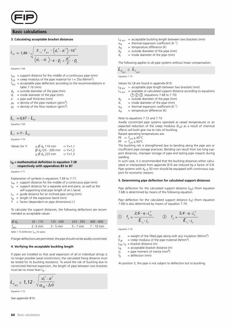
Basic calculations
64 Basic calculations
3. Calculating acceptable bracket distances
Equation 7.68
LM = support distance for the middle of a continuous pipe (mm)
EcR = creep modulus of the pipe material for t = 25a (N/mm2)
facc = acceptable pipe deflection according to the recommendations in
table 7.16 (mm)
de = outside diameter of the pipe (mm)
di = inside diameter of the pipe (mm)
e = pipe wall thickness (mm)
�P = density of the pipe medium (g/cm3)
�F = density of the flow medium (g/cm3)
Equation 7.69
Equation 7.70
Values for Y: < O de 110 mm -> Y=1,1
O de125 - 200 mm -> Y=1,2
< O de 225 mm -> Y=1,3
Equation 7.71
Explanation of symbols in equations 7.69 to 7.71:
LM = support distance for the middle of a continuous pipe (mm)
LE = support distance for a separate and end piece, as well as the
self-supporting total pipe length of an L bend.
LV = guide distance for an inclined pipe string (mm)
LB = length of the expansion bend (mm)
Y = factor (dependent on pipe dimensions) (-)
To calculate the support distances, the following deflections are recom-
mended as acceptable values:
If larger deflections are permitted, the pipe should not be axially constricted.
4. Verifying the acceptable buckling length
If pipes are installed so that axial expansion of all or individual strings is
no longer possible (axial constriction), the calculated fixing distance must
be tested for its buckling resistance. To avoid the risk of buckling due to
constricted thermal expansion, the length of pipe between two brackets
must be no more than LK .
Equation 7.72
See appendix B10.
LK acc = acceptable buckling length between two brackets (mm)
�� = thermal expansion coefficient (K-1)
�� = temperature difference (K)
de = outside diameter of the pipe (mm)
di = inside diameter of the pipe (mm)
The following applies to all pipe systems without linear compensation:
Equation 7.73
Values for LB are found in appendix B10:
LB acc = acceptable pipe length between two brackets (mm)
LS acc = available or calculated support distance according to equations
1 2 3 (equations 7.68 to 7.70)
de = outside diameter of the pipe (mm)
di = inside diameter of the pipe (mm)
�� = thermal expansion coefficient (K-1)
�� = temperature difference (K)
Note to equations 7.72 and 7.73:
Axially constricted pipe systems operated at raised temperatures or an
expected reduction of the creep modulus (EcR) as a result of chemical
effects will both give rise to risks of buckling.
Raised operating temperatures are:
PE -> Tcrit > 45°C
PP -> Tcrit > 60°C
The buckling risk is strengthened due to bending along the pipe axis or
insufficient pipe storage practices. Bending can result from too long sup-
port distances, improper storage of pipe and lasting pipe impacts during
welding.
In such case, it is recommended that the buckling distances either calcu-
lated or interpolated from appendix B10 are reduced by a factor of 0.8.
Pipe systems with de < 50 mm should be equipped with continuous sup-
port for economic reasons.
5. Determining pipe deflection for calculated support distances
Pipe deflection for the calculated support distance (LM) (from equation
7.68) is determined by means of the following equation.
Pipe deflection for the calculated support distance (LE) (from equation
7.69) is also determined by means of equation 7.74.
Equation 7.74
q = weight of the filled pipe along with any insulation (N/mm2)
EcR = creep modulus of the pipe material (N/mm2)
LM, LE = bracket distance (m)
LB = acceptable bracket distance (m)
JP = pipe moment of inertia (mm4)
fD = deflection (mm)
At position 3, the pipe is not subject to deflection but to buckling.
O de 20 - 110 125 - 200 225 - 355 400 - 600
facc 2 -3 mm 3 - 5 mm 5 - 7 mm 7 - 10 mm
Table 7.16 Deflection facc for pipes
LB = mathematical definition in equation 7.28
respectively with appendices B3 to B7

65
Jointing
Jointing
8 Jointing
8.1 General
In planning and installing PE pipe systems, the planning and/or installa-
tion organisations can select a series of different jointing techniques. The
nature of the load, the type of installation, the economics and the local
conditions have large influences on the choice of appropriate connecting
method. The nature of the pipe connection can have lasting positive and
negative consequences for the manufacturing costs of a pipe system. Cri-
teria for selecting the most appropriate jointing technique are:
- operational reliability
- accessibility
- level of sealing
- effects of the medium to which it will be exposed
- cost outlay
- internal pressure load of the pipe system
The planner and fitter of plastic pipe systems can choose between a
detachable and non-detachable connecting technique. Various procedu-
res are available for possible solutions. The detachable connection con-
tains elements that generally enable non-destructive disassembly and re-
assembly without large additional expense.
Figure 8.1 Detachable and non-detachable pipe connections
8.2 Detachable connections
8.2.1 General
In general, the group of detachable connecting elements for PE pipe sys-
tems consists of:
- flanges
- push-fit connections
- unions
- compression fittings
The individual jointing techniques in this group will be discussed below.
8.2.2 Flange joints
Connections to such components as pumps or valves are normally made
by means of flange joints. The elements of the flange joint used in plastic
pipe construction are the stub flange, backing ring, gasket and bolts with
washers (possibly lock washers) and hex nuts. Flange joints can be either
backing ring connections or blind flange joints. A blind flange joint is
usually used to seal the end of a pipe. The fixed flange variant is generally
ruled out due to higher costs. A backing ring connection is, in most
cases, the substantially less expensive variant whenever a direct compari-
son is made, and therefore fixed flange joints are only of limited signifi-
cance in the choice of flange joints.
The backing rings used as connecting elements in the plastic pipe con-
struction are constructed from metal materials (e.g. steel, aluminium),
fibre glass reinforced plastic or a combination of plastic and metal. The
ease of assembly involved in their use and especially the higher operating
reliability give backing ring connections definite advantages over fixed
flange joints.
Figure 8.2 Flange joint
Figure 8.3 Cross-section of a flange joint
The gasket, nearly always in the form of a flat ring gasket, is available in
various material and material qualities. Use is often made of gaskets
composed of elastomers or elastomer compounds, such as neoprene,
hypalon or viton. Hard gaskets have proven to be less suited or even
unsuitable on account of their limited formability. The use of elastomer
flat gaskets without steel inlays frequently results in leakage at higher
internal pressures (e.g. during pressure testing). It is therefore recommen-
ded for use to be made of armoured gaskets with a convex cross-section.
Their use is especially advisable when the internal pressure (operating
pressure) comes close to the pipe's pressure rating. An additional impro-
vement in the level of sealing is obtained when the inside of the gasket
has the form of an O-ring. O-rings, double chamber gaskets, etc. are to
be used in cases involving high internal pressures, especially when vacu-
ums are involved as well. Gasket sizes are to be chosen so that the inside
pipe diameter is not reduced by any excess gasket material, or that fissu-
res can occur allowing fluid to penetrate the seal (with risk of sedimenta-
tion in the fissure!). During assembly, care must also be taken to ensure
that the bolts are tightened evenly and the gasket and sealing surfaces
are clean. Table 8.1 shows the standard values for the bolt torques in
flange joints.
Pipe connection options
Detachable connections Non-detachable connections
Flange joints Welding
Unions Gluing
Couplings Push-fit end trust bearing
Push-fit joints
Expansion sockets
Compression fittings
1 Backing ring
2 Stub flange
3 Gasket
4 Bolt
5 Hex nut
6 Washer

Jointing
66 Jointing
Standard bolt torques in flange joints of thermoplastic pipes
(DVS 2210 Part 1)
8.2.3 Push-fit connection
A push-fit connection is the general name given to all spigot and socket
connections. The push-fit socket to be used will be explained in the follo-
wing section.
Figure 8.4 Push-fit spigot
Figure 8.5 Cross-section of a connection with a push-fit socket
Push-fit and expansion sockets
The leak-tightness of a pipe connection with a push-fit and/or expansion
socket is essentially achieved by applying the forces of a sealing element
to the connecting pipe and/or fitting. In addition, the existing internal
pressure helps to strengthen the radial sealing force. Small pipe deflecti-
ons can be tolerated, as well as longitudinal movements corresponding
to the distance that can be absorbed between the socket and seal seat.
Socket connections should only be used in pressure applications involving
pipe systems that are free of underpressure. In principle, use is to be enti-
rely avoided in pipe systems subject to internal pressure and another join-
ting technique chosen.
Figure 8.6 Functional principle of the expansion socket
8.2.4 Unions
Figure 8.7 Screw-thread joint
Figure 8.8 Cross-section of a union
de
(mm)
DN
(mm)
Bolt tightening torque (Nm)
Flat ring gasket Profile gasket O-ring gasket
(pacc < 10 bar) (pacc < 16 bar) (pacc < 16 bar)
20 15 15 10 10
25 20 15 15 15
32 25 15 15 15
40 32 20 15 15
50 40 30 15 15
63 50 35 20 20
75 65 40 20 20
90 80 40 20 20
110 100 40 20 20
125 100 40 20 20
140 125 50 30 30
160 150 60 40 35
180 150 60 40 35
200 200 70 (1) 50 40
225 200 70 (1) 50 40
250 250 80 (1) 55 50
280 250 80 (1) 55 50
315 300 100 (1) 60 55
355 350 100 (1) 70 60
400 400 120 (1) 80 65
450 500 190 (1) 90 70
500 500 190 (1) 90 70
560 600 220 (1) 100 80
630 600 220 (1) 100 80
1 Socket
2 Seal
1 Plug
2 Lip seal ring
A Total insertion depth
B Minimum insertion depth
C Expansion capacity
1 Section to be inserted
2 Section to be screwed on
3 Ring nut
4 O-ring
(1) for Pacc < 6 bar
Table 8.1 Bolt tightening torques for flat, profile and O-ring gaskets

67
Jointing
Jointing
These types of connecting elements are used in water lines as well as in
transitions from plastic to other materials. The ease of assembly make them
an especially valued connecting technique for small pipe sizes. Tempera-
ture effects can restrict application in pipe systems due to the flow behavi-
our of plastic. Each application must be carefully tested.
8.2.5 Compression fitting
Compression fittings are used to connect pipes in a quick and easy manner.
A pressure chamber contains a sealing ring. Screwing in the fitting causes
the sealing ring to be clamped against the pipe. NBR O-rings are used to
connect the PE pipes. Special compression rings can be adopted to connect
PE pipes with other types of material, such as PVC-U, PVC-C, PP, PE-X cop-
per, lead and steel. Compression fittings are used in swimming-pool sys-
tems, for (drinking) water distribution, irrigation and telecommunications
as well as in the mining industry and horticulture.
Figure 8.9 Compression fitting
Figure 8.10 Compression principle
8.3 Non-detachable connections
8.3.1 General
Non-detachable jointing techniques are the most commonly used connec-
tion techniques in PE pipe construction. Welding is an extremely important
form of connection used for PE fitting in plastic pipe construction. For this
reason, welding has been made the focus of this Specification Manual
and, on account of its importance, will be discussed in a separate chapter.
8.3.2 Welding
Welding has a special significance in pipe installation as well as in the
production of PE shafts, tanks and special welded components. Many of
the welding techniques described in chapter 9 are based on the princi-
ples in the DVS guidelines and have been adopted either directly or in
analogous forms.
8.3.3 Gluing
Up to now, gluing has not been used in PE pipe construction. The charac-
teristics of the plastics in question (polyolefin) make them unsuitable for
glued connections (due to their "waxiness"), as their surfaces are not
softened by adhesives. Special multi-component adhesives allow only
limited connections to be formed that cannot be subject to mechanical
loads and that are technically insignificant.
8.3.4 Push-fit socket end thrust bearing
Push-Fast is a unique spigot and socket type water jointing system, which
combines the benefits of PE pipe with the ease of conventional push-fit
joints. Unlike most spigot and socket type systems, Push-Fast has a speci-
ally designed and patented socket, which incorporates a tough thermo-
plastic 'grip' ring located in a tapered groove. This allows the joint to
resist end-thrust generated by the internal pressure and eliminates the
need for anchors or thrust blocks.
Figure 8.11 Section through assembled Push-Fast Joint showing grab ring and sealing
Push-Fast heads can easily be butt-welded to pipe lengths and coils. It is
quick and easy to install. Suitable for underground pipe systems in subsi-
dence areas and to limited space installation. The pipe system is immedi-
ately serviceable after assembly.
The performance of the Push-Fast joint depends on the efficiency of the
seal between the elastromeric sealing ring, the pipe and the socket.
Damage to the pipe or fittings or the presence of dirt or grit will adversely
affect the performance of the joint.
With pipe inserted Hydraulic seal and
mechanical clamp with
locked ring nut
Function under
pressure
1 Clamp ring
2 Compression ring
3 Sealing system with
limited size tolerance
3 2 1

Jointing
68 Jointing
8.4 Chapter summary
Connection method In plastic pipe construction, there are two types of connecting techniques: detachable and non-detachable.
Detachable connection technique Detachable connections can be easily disassembled and re-assembled without destroying the connection.
Non-detachable connection technique Disassembly usually involves destruction of at least one of the connecting elements.
Flange connections Can be fixed or backing ring connections. Backing ring connections consist of the components: stub flange,
backing ring and gasket. A combination of stub flange, backing ring, blind flange and gasket can be used to
seal pipes. At higher loads, backing ring connections are preferable to fixed flange connections.
Seals Seals are needed to seal connections between two connecting elements. In the flange connections used in
plastic pipe construction, flat gaskets (with and without steel inlays) and O-rings are mostly used. The mate-
rial of the seal is adaptable to the flow medium.
Push-fit and expansion sockets These are simple detachable connections. However, they should only be used in pressureless (under and
overpressure free) pipe systems. They are therefore appropriate for pressureless drainage and/or sewerage
systems.
Unions Unions are quick connection devices. They are detachable connections and enable simple assembly,
disassembly and re-assembly without special implements and tools.
Welding Welding is one of the most commonly used jointing techniques in plastic pipe construction. Various plastic
welding procedures are used to manufacture fittings from pipes and pipe segments, joints made of pieces of
pipe, as well as plastic shafts, tanks and other special components. Welding processes non-detachable con-
nection techniques.
Gluing Gluing is only very conditionally meaningful and possible as an appropriate jointing technique for polyolefin
materials. A bond is produced only with special multi-component adhesives. These glued connections are
not at all capable of withstanding mechanical loads.
Push-fit socket end thrust bearing Plug and socket type water jointing system with push fit joints. A tough thermoplastic 'grip' ring located in
a tapered groove allows the joint to resist end-thrust. It is quick and easy to install. No anchors or thrust
blocks required. Suitable for ground subsidence areas and to limited space installation. Immediately service-
able.

PRODUCT TABLES

Foreword
70 Foreword
Foreword catalogue
Technical dataAll data complies with the actual technical data at time of print of this
publication. All dimensions are in mm, unless otherwise stated. FIP cannot
be held responsible for printing errors and temporary changes in this cata-
logue. For more information contact our Technical Support.
ApprovalsThe FIP product range has the following approvals and certificates:
- FIP spigot fittings: Kiwa and DVGW
- FIP S.p.A.: ISO 9001 and ISO 14001
Assembly instructionsThe following guidelines are applicable for the jointing of the different
product ranges:
- FIP spigot fittings according the appicable
(inter)national standard
- Electrofusion fittings according FRIALEN assembly instruction or the
applicable (inter)national standard.
Delivery conditionsOur general terms and conditions are applicable.
Inspection certificateInspection certificates can be issued and have to be requested at time of
ordering. FIP will charge €25,- handling fee.
DistributionThe FIP pressure system is sold through a network of distributors. The
contact details of the distributor in your country can be requested at the
Customer Service department or can be found on our website:
www.fipnet.it.
StorageFittings need to be stored in a dry environment. We recommand to keep
the fittings as long as possible in the original packing to prevent corrosion
and pollution.
Return goodsProducts can only be returned after FIP has expressly given its consent in
writing, an handling fee will be charged.
ServiceRealising dureable and reliable joints request more than just good products.
By giving training, supplying product information and site support we try
to inform contractors, consultants, end-users and distributors about the
properties, applications and assembly of PE pressure pipe systems. We do
this with only one goal:
Safe and reliable jointings!
ABBREVIATONS
AG article group
Art. Nr. article number
DN nominal size
de outside diameter
e wall thickness of a pipe
G cilindrical pipe threads where pressure-tight joints are not
made on the threads ISO 228
L length of fitting
l length of spigot
q package quantity
R male pipe threads where pressure-tight joints are made on the
threads ISO 7
Rp cilindrical female pipe threads where pressure-tight joints are
made on the threads ISO 7
Rc conical female pipe threads where pressure-tight joints are
made on the threads ISO 7
SDR ratio between outer diameter / wall thickness
EN European standard
ISO international standard
DIN national standard in Germany
ASTM American standard
S class indication ISO-S = (SDR-1)/2
o.r. on request

71
Short fittings for butt-welding
Stub flanges
With grooved jointing face.
Stub flange short QBE SDR 33 PE100SDR 33
for butt-welding water 3,2 bar
de Art. Nr. h l d1 d2 L
110 QBE33110 18 34 125 158 80
125 QBE33125 18 38 132 158 80
140 QBE33140 18 32 155 188 80
160 QBE33160 18 26 175 212 80
180 QBE33180 18 31 183 212 80
200 QBE33200 18 34 232 268 100
225 QBE33225 18 46 235 268 100
250 QBE33250 20 71 285 320 132
280 QBE33280 20 62 291 320 128
315 QBE33315 20 71 335 370 136
355 QBE33355 23 57 373 430 120
400 QBE33400 26 49 427 482 120
450 QBE33450 33 27 514 585 120
500 QBE33500 33 37 530 585 120
560 QBE33560 35 25 615 685 120
630 QBE33630 35 45 642 685 120
710 QBE33710 *
* fabrication on order, returning not possible
35 35 737 800 120
800 QBE33800 * 36 34 840 905 120
900 QBE33900 * 40 30 944 1005 120
1000 QBE331000 * 42 28 1047 1110 140
1200 QBE331200 * 50 20 1245 1330 140

72
Short fittings for butt-welding
Stub flanges
With grooved jointing face.
Stub flange short QBE SDR 17 PE100SDR 17
for butt-welding water 10 bar/gas 5 bar
de Art. Nr. h l d1 d2 L
50 QBE17050 12 21 61 88 50
63 QBE17063 14 16 75 102 50
75 QBE17075 16 14 89 122 50
90 QBE17090 17 33 105 138 80
110 QBE17110 18 27 125 158 80
125 QBE17125 18 42 132 158 80
140 QBE17140 18 34 155 188 80
160 QBE17160 18 34 175 212 80
180 QBE17180 20 60 182 212 80
200 QBE17200 24 36 232 268 100
225 QBE17225 24 46 235 268 100
250 QBE17250 25 35 285 320 100
280 QBE17280 25 45 291 320 100
315 QBE17315 25 35 335 370 100
355 QBE17355 30 30 373 430 120
400 QBE17400 33 42 427 482 120
450 QBE17450 46 14 514 585 120
500 QBE17500 46 24 530 585 120
560 QBE17560 50 10 615 685 120
630 QBE17630 50 30 642 685 120
710 QBE17710 *
* fabrication on order, returning not possible
50 20 737 800 120
800 QBE17800 * 52 18 840 905 120
900 QBE17900 * 55 15 944 1005 120
1000 QBE171000 * 60 10 1047 1110 140

73
Short fittings for butt-welding
Stub flanges
With grooved jointing face.
Stub flange short QBE SDR 11 PE100SDR 11
for butt-welding water 16 bar/gas 10 bar
de Art. Nr. h l d1 d2 L
20 QBE11020 7 30 27 45 50
25 QBE11025 9 26 33 58 50
32 QBE11032 10 25 40 68 50
40 QBE11040 11 24 50 78 50
50 QBE11050 12 21 61 88 50
63 QBE11063 14 16 75 102 50
75 QBE11075 16 14 89 122 50
90 QBE11090 17 33 105 138 80
110 QBE11110 18 27 125 158 80
125 QBE11125 25 25 132 158 80
140 QBE11140 25 27 155 188 80
160 QBE11160 25 34 175 212 80
180 QBE11180 30 60 182 212 80
200 QBE11200 32 36 232 268 100
225 QBE11225 32 46 235 268 100
250 QBE11250 35 35 285 320 100
280 QBE11280 35 45 291 320 100
315 QBE11315 35 35 335 370 100
355 QBE11355 40 30 373 430 120
400 QBE11400 46 29 427 482 120
450 QBE11450 60 20 514 585 120
500 QBE11500 60 20 530 585 120
560 QBE11560 60 30 615 685 120
630 QBE11630 60 20 642 685 120
710 QBE11710 *
* fabrication on order, returning not possible
67 20 737 800 120
800 QBE11800 * 74 20 840 905 120

74
Short fittings for butt-welding
Stub flanges
With flat jointing face.Suitable for installation on both sides of the butterfly valve.Dimensions are adapted to the profile backing ring for stub flange.
With flat jointing face.Suitable for installation on both sides of the butterfly valve.Dimensions are adapted to the profile backing ring for stub flange.
Stub flange short QBE/FK SDR 17 for FIP butterfly valve type FE and FK PE100SDR 17
for butt-welding water 10 bar
de/DN Art. Nr. h l d1 d2 d6/ß L
50/40 QPE17050 12 21 61 88 50
63/50 QPE17063 14 16 75 102 50
75/65 QPE17075 16 14 89 122 50
90/80 QPE17090 17 33 105 138 80
110/100 QPE17110 18 27 125 158 80
125/100 QPE17125 18 42 132 158 80
140/125 QPE17140 18 34 155 188 80
160/150 QPE17160 18 34 175 212 80
180/150 QPE17180 20 60 182 212 80
200/200 QBE17FK200 *
* machined for free movement of disc
24 36 232 268 179/20° 100
225/200 QPE17225 24 46 235 268 100
250/250 QBE17FK250 * 25 35 285 320 233/25° 100
280/250 QPE17280 25 45 291 320 100
315/300 QBE17FK315 * 25 35 335 370 288/25° 100
Stub flange short QBE/FK SDR 11 for FIP butterfly valve type FE and FK PE100SDR 11
for butt-welding water 16 bar
de/DN Art. Nr. h l d1 d2 d6/ß L
50/40 QPE11050 12 21 61 88 50
63/50 QPE11063 14 16 75 102 50
75/65 QPE11075 16 14 89 122 50
90/80 QPE11090 17 33 105 138 80
110/100 QPE11110 18 27 125 158 80
125/100 QPE11125 25 25 132 158 80
140/125 QPE11140 25 27 155 188 80
160/150 QBE11FK160 *
* machined for free movement of disc
25 34 175 212 148/20° 80
180/150 QPE11180 30 60 182 212 80
200/200 QBE11FK200 * 32 36 232 268 192/25° 100
225/200 QBE11FK225 * 32 46 235 268 201/15° 100
250/250 QBE11FK250 * 35 35 285 320 233/25° 100
280/250 QBE11FK280 * 35 45 291 320 257/25° 100
315/300 QBE11FK315 * 35 35 335 370 288/25° 100

75
Short fittings for butt-welding
Stub flanges
With flat jointing face.Suitable for installation on entrance side. Install stub flange extended short CR/FR on exit side.Dimensions are adapted to the profile backing ring for stub flange.
With flat jointing face.Suitable for installation on entrance side. Install stub flange extended short CR/FR on exit side. Dimensions are adapted to the profile backing ring for stub flange.
Stub flange short QPE SDR 17 for entrance side FIP check valve type CR and FR PE100SDR 17
for butt-welding water 10 bar
de/DN Art. Nr. h l d1 d2 L
50/40 QPE17050 12 21 61 88 50
63/50 QPE17063 14 16 75 102 50
75/65 QPE17075 16 14 89 122 50
90/80 QPE17090 17 33 105 138 80
110/100 QPE17110 18 27 125 158 80
125/100 QPE17125 18 42 132 158 80
140/125 QPE17140 18 34 155 188 80
160/150 QPE17160 18 34 175 212 80
180/150 QPE17180 20 60 182 212 80
200/200 QPE17200 24 36 232 268 100
225/200 QPE17225 24 46 235 268 100
250/250 QPE17250 25 35 285 320 100
280/250 QPE17280 25 45 291 320 100
315/300 QPE17315 25 35 335 370 100
Stub flange short QPE SDR 11 for entrance side FIP check valve type CR and FR PE100SDR 11
for butt-welding water 16 bar
de/DN Art. Nr. h l d1 d2 L
50/40 QPE11050 12 21 61 88 50
63/50 QPE11063 14 16 75 102 50
75/65 QPE11075 16 14 89 122 50
90/80 QPE11090 17 33 105 138 80
110/100 QPE11110 18 27 125 158 80
125/100 QPE11125 25 25 132 158 80
140/125 QPE11140 25 27 155 188 80
160/150 QPE11160 25 34 175 212 80
180/150 QPE11180 30 60 182 212 80
200/200 QPE11200 32 36 232 268 100
225/200 QPE11225 32 46 235 268 100
250/250 QPE11250 35 35 285 320 100
280/250 QPE11280 35 45 291 320 100
315/300 QPE11315 35 35 335 370 100

76
Short fittings for butt-welding
Stub flanges
With flat jointing face. Extended for free movement of disc.Suitable for installation on exit side. Install stub flange short CR/FR on entrance side.Dimensions are adapted to the profile backing ring for stub flange. Fabrication on order.
With flat jointing face. Extended for free movement of disc.Suitable for installation on exit side. Install stub flange short CR/FR on entrance side. Dimensions are adapted to the profile backing ring for stub flange. Fabrication on order.
Stub flange extended short QBXE SDR 17 for exit side FIP check valve type CR and FR PE100SDR 17
for butt-welding water 10 bar
de/DN Art. Nr. h l d1 d2 L R
50/40 QBXE17050 12 20 61 90 50 3
63/50 QBXE17063 14 20 75 105 54 4
75/65 QBXE17075 16 20 89 125 58 4
90/80 QBXE17090 17 40 105 138 92 4
110/100 QBXE17110 18 40 125 160 92 4
140/125 QBXE17140 18 40 155 190 100 4
160/150 QBXE17160 18 40 175 215 120 4
225/200 QBXE17225 24 40 235 270 165 4
280/250 QBXE17280 25 40 291 325 195 6
315/300 QBXE17315 25 40 335 375 250 6
Stub flange extended short QBXE SDR 11 for exit side FIP check valve type CR and FR PE100SDR 11
for butt-welding water 16 bar
de/DN Art. Nr. h l d1 d2 L R
50/40 QBXE11050 12 20 61 90 50 3
63/50 QBXE11063 14 20 75 105 56 4
75/65 QBXE11075 16 20 89 125 65 4
90/80 QBXE11090 17 35 105 138 92 4
110/100 QBXE11110 18 35 125 160 92 4
140/125 QBXE11140 18 40 155 190 110 4
160/150 QBXE11160 18 40 175 215 120 4
225/200 QBXE11225 26 56 235 270 180 4
280/250 QBXE11280 35 40 291 325 220 6
315/300 QBXE11315 35 40 335 375 270 6

77
Short fittings for butt-welding
Tees
Tee 90° short TBE SDR 33 PE100SDR 33
for butt-welding water 3,2 bar
de Art. Nr. L Z l
110 TBE33110 249 121 50
140 TBE33140 293 145 48
160 TBE33160 318 160 55
180 TBE33180 356 175 59
200 TBE33200 385 194 55
225 TBE33225 442 212 59
250 TBE33250 465 232 70
280 TBE33280 536 268 80
315 TBE33315 530 263 75
355 TBE33355 658 330 95
400 TBE33400 690 345 104
450 TBE33450 890 450 130
500 TBE33500 895 450 130
Tee 90° short TBE SDR 17 PE100SDR 17
for butt-welding water 10 bar/gas 5 bar
de Art. Nr. L Z l
50 TBE17050 116 58 21
63 TBE17063 146 73 24
75 TBE17075 170 85 28
90 TBE17090 200 100 23
110 TBE17110 240 120 43
125 TBE17125 250 125 26
140 TBE17140 280 140 32
160 TBE17160 350 160 40
180 TBE17180 390 195 73
200 TBE17200 430 215 64
225 TBE17225 490 245 72
250 TBE17250 550 275 86
280 TBE17280 620 310 105
315 TBE17315 700 350 111
355 TBE17355 680 340 101
400 TBE17400 680 338 95
450 TBE17450 900 450 130
500 TBE17500 900 450 130

78
Short fittings for butt-welding
Tees
Tee 90° short TBE SDR 11 PE100SDR 11
for butt-welding water 16 bar/gas 10 bar
de Art. Nr. L Z l
20 TBE11020 50 25 8
25 TBE11025 60 30 10
32 TBE11032 80 40 12
40 TBE11040 88 44 16
50 TBE11050 116 58 21
63 TBE11063 146 73 24
75 TBE11075 170 85 28
90 TBE11090 200 100 23
110 TBE11110 240 120 43
125 TBE11125 250 125 26
140 TBE11140 280 140 32
160 TBE11160 350 160 40
180 TBE11180 390 195 73
200 TBE11200 430 215 64
225 TBE11225 490 245 72
250 TBE11250 550 275 86
280 TBE11280 620 310 105
315 TBE11315 700 350 111
355 TBE11355 680 340 101
400 TBE11400 680 338 95
450 TBE11450 900 450 130
500 TBE11500 900 450 130
Tee 90° reduced short TRBE SDR 17 PE100with reduced branch SDR 17for butt-welding water 10 bar/gas 5 bar
de1/de2 Art. Nr. L Z l1 l2
110/90 TRBE17110090 240 115 48 38
140/63 TRBE17140063 300 120 83 32
140/75 TRBE17140075 300 130 81 35
140/90 TRBE17140090 300 130 81 41
140/110 TRBE17140110 300 137 50 47
160/110 TRBE17160110 320 145 56 38
160/125 TRBE17160125 315 150 58 47
180/63 TRBE17180063 358 134 125 30
180/75 TRBE17180075 360 140 112 30
180/125 TRBE17180125 358 160 92 50
225/110 TRBE17225110 440 264 89 89
225/125 TRBE17225125 445 180 135 40
225/160 TRBE17225160 470 200 89 60

79
Short fittings for butt-welding
Tees
Tee 90° reduced short TRBE SDR 11 PE100with reduced branch SDR 11for butt-welding water 16 bar/gas 10 bar
de1/de2 Art. Nr. L Z l1 l2
90/50 TRBE11090050 213 90 53 28
110/32 TRBE11110032 244 94 66 22
110/50 TRBE11110050 244 103 66 27
125/63 TRBE11125063 278 112 70 31
140/63 TRBE11140063 305 120 83 32
140/75 TRBE11140075 305 130 81 35
140/90 TRBE11140090 305 130 81 41
140/110 TRBE11140110 305 140 50 47
160/110 TRBE11160110 320 145 56 38
160/125 TRBE11160125 325 150 58 47
180/63 TRBE11180063 358 134 125 30
180/75 TRBE11180075 352 140 112 30
180/110 TRBE11180110 365 158 106 48
180/125 TRBE11180125 366 166 92 50
225/110 TRBE11225110 440 264 89 88
225/125 TRBE11225125 456 178 135 40
225/160 TRBE11225160 470 200 89 60

80
-- to be continued --
Short fittings for butt-welding
Tees
Tee 90° reduced machined short TRCBE SDR17 - pressure class conform PE100with reduced branch SDR 17for butt-welding water 10 bar/gas 5 bar
de1/de2 Art. Nr. L Z
280/63 TRCBE17280063 270 365
280/75 TRCBE17280075 280 365
280/90 TRCBE17280090 295 365
280/110 TRCBE17280110 315 365
280/125 TRCBE17280125 330 365
280/140 TRCBE17280140 345 365
280/160 TRCBE17280160 365 365
280/180 TRCBE17280180 385 365
280/200 TRCBE17280200 405 365
280/225 TRCBE17280225 430 365
315/75 TRCBE17315075 280 380
315/90 TRCBE17315090 295 380
315/110 TRCBE17315110 315 380
315/125 TRCBE17315125 330 380
315/140 TRCBE17315140 345 380
315/160 TRCBE17315160 365 380
315/180 TRCBE17315180 385 380
315/200 TRCBE17315200 405 380
315/225 TRCBE17315225 430 380
315/250 TRCBE17315250 455 380
355/90 TRCBE17355090 305 400
355/110 TRCBE17355110 325 400
355/125 TRCBE17355125 340 400
355/140 TRCBE17355140 355 400
355/160 TRCBE17355160 375 400
355/180 TRCBE17355180 395 400
355/200 TRCBE17355200 415 400
355/225 TRCBE17355225 440 400
355/250 TRCBE17355250 465 400
355/280 TRCBE17355280 500 400
400/110 TRCBE17400110 325 425
400/125 TRCBE17400125 340 425
400/140 TRCBE17400140 355 425
400/160 TRCBE17400160 375 425
400/180 TRCBE17400180 395 425
400/200 TRCBE17400200 415 425
400/225 TRCBE17400225 440 425
400/250 TRCBE17400250 465 425
400/280 TRCBE17400280 500 425
400/315 TRCBE17400315 535 425
450/125 TRCBE17450125 340 450
450/140 TRCBE17450140 355 450
450/160 TRCBE17450160 375 450
450/180 TRCBE17450180 395 450
450/200 TRCBE17450200 415 450
450/225 TRCBE17450225 440 450
450/250 TRCBE17450250 465 450
450/280 TRCBE17450280 500 450
450/315 TRCBE17450315 535 450
450/355 TRCBE17450355 575 450
500/140 TRCBE17500140 355 475
500/160 TRCBE17500160 375 475
500/180 TRCBE17500180 395 475
500/200 TRCBE17500200 415 475
500/225 TRCBE17500225 440 475
500/250 TRCBE17500250 465 475

81
Tee 90° reduced machined short TRCBE SDR17 - pressure class conform - continuation -
Short fittings for butt-welding
Tees
Pressure rating guaranteed, branch extended with pipe.Fabrication on order, returning not possible.
500/280 TRCBE17500280 500 475
500/315 TRCBE17500315 535 475
500/355 TRCBE17500355 575 475
500/400 TRCBE17500400 620 475
560/160 TRCBE17560160 375 500
560/180 TRCBE17560180 395 500
560/200 TRCBE17560200 415 500
560/225 TRCBE17560225 440 500
560/250 TRCBE17560250 465 500
560/280 TRCBE17560280 500 500
560/315 TRCBE17560315 535 500
560/355 TRCBE17560355 575 500
560/400 TRCBE17560400 620 500
560/450 TRCBE17560450 670 500
560/560 TRCBE17560560 780 500
630/180 TRCBE17630180 395 540
630/200 TRCBE17630200 415 540
630/225 TRCBE17630225 440 540
630/250 TRCBE17630250 465 540
630/280 TRCBE17630280 500 540
630/315 TRCBE17630315 535 540
630/355 TRCBE17630355 575 540
630/400 TRCBE17630400 620 540
630/450 TRCBE17630450 670 540
630/500 TRCBE17630500 720 540
630/630 TRCBE17630630 850 540
710/180 TRCBE17710180 395 620
710/200 TRCBE17710200 415 620
710/225 TRCBE17710225 440 620
710/250 TRCBE17710250 465 620
710/280 TRCBE17710280 500 620
710/315 TRCBE17710315 535 620
710/355 TRCBE17710355 575 620
710/400 TRCBE17710400 620 620
710/450 TRCBE17710450 670 620
710/500 TRCBE17710500 720 620
710/560 TRCBE17710560 780 620
710/710 TRCBE17710710 950 650
de1/de2 Art. Nr. L Z

82
-- to be continued --
Short fittings for butt-welding
Tees
Tee 90° reduced machined short TRCBE SDR11 - pressure class conform PE100with reduced branch SDR 11for butt-welding water 16 bar/gas 10 bar
de1/de2 Art. Nr. L Z
280/63 TRCBE11280063 270 365
280/75 TRCBE11280075 280 365
280/90 TRCBE11280090 295 365
280/110 TRCBE11280110 315 365
280/125 TRCBE11280125 330 365
280/140 TRCBE11280140 345 365
280/160 TRCBE11280160 365 365
280/180 TRCBE11280180 385 365
280/200 TRCBE11280200 405 365
280/225 TRCBE11280225 430 365
315/75 TRCBE11315075 280 380
315/90 TRCBE11315090 295 380
315/110 TRCBE11315110 315 380
315/125 TRCBE11315125 330 380
315/140 TRCBE11315140 345 380
315/160 TRCBE11315160 365 380
315/180 TRCBE11315180 385 380
315/200 TRCBE11315200 405 380
315/225 TRCBE11315225 430 380
315/250 TRCBE11315250 455 380
355/90 TRCBE11355090 305 400
355/110 TRCBE11355110 325 400
355/125 TRCBE11355125 340 400
355/140 TRCBE11355140 355 400
355/160 TRCBE11355160 375 400
355/180 TRCBE11355180 395 400
355/200 TRCBE11355200 415 400
355/225 TRCBE11355225 440 400
355/250 TRCBE11355250 465 400
355/280 TRCBE11355280 500 400
400/110 TRCBE11400110 325 425
400/125 TRCBE11400125 340 425
400/140 TRCBE11400140 355 425
400/160 TRCBE11400160 375 425
400/180 TRCBE11400180 395 425
400/200 TRCBE11400200 415 425
400/225 TRCBE11400225 440 425
400/250 TRCBE11400250 465 425
400/280 TRCBE11400280 500 425
400/315 TRCBE11400315 535 425
450/125 TRCBE11450125 340 450
450/140 TRCBE11450140 355 450
450/160 TRCBE11450160 375 450
450/180 TRCBE11450180 395 450
450/200 TRCBE11450200 415 450
450/225 TRCBE11450225 440 450
450/250 TRCBE11450250 465 450
450/280 TRCBE11450280 500 450
450/315 TRCBE11450315 535 450
450/355 TRCBE11450355 575 450
500/140 TRCBE11500140 355 475
500/160 TRCBE11500160 375 475
500/180 TRCBE11500180 395 475
500/200 TRCBE11500200 415 475
500/225 TRCBE11500225 440 475
500/250 TRCBE11500250 465 475

83
Tee 90° reduced machined short TRCBE SDR11 - pressure class conform - continuation -
Short fittings for butt-welding
Tees
Pressure rating guaranteed, branch extended with pipe.Fabrication on order, returning not possible.
500/280 TRCBE11500280 500 475
500/315 TRCBE11500315 535 475
500/355 TRCBE11500355 575 475
500/400 TRCBE11500400 620 475
560/160 TRCBE11560160 375 500
560/180 TRCBE11560180 395 500
560/200 TRCBE11560200 415 500
560/225 TRCBE11560225 440 500
560/250 TRCBE11560250 465 500
560/280 TRCBE11560280 500 500
560/315 TRCBE11560315 535 500
560/355 TRCBE11560355 575 500
560/400 TRCBE11560400 620 500
560/450 TRCBE11560450 670 500
560/560 TRCBE11560560 780 500
630/180 TRCBE11630180 395 540
630/200 TRCBE11630200 415 540
630/225 TRCBE11630225 440 540
630/250 TRCBE11630250 465 540
630/280 TRCBE11630280 500 540
630/315 TRCBE11630315 535 540
630/355 TRCBE11630355 575 540
630/400 TRCBE11630400 620 540
630/450 TRCBE11630450 670 540
630/500 TRCBE11630500 720 540
630/630 TRCBE11630630 850 540
710/180 TRCBE11710180 395 620
710/200 TRCBE11710200 415 620
710/225 TRCBE11710225 440 620
710/250 TRCBE11710250 465 620
710/280 TRCBE11710280 500 620
710/315 TRCBE11710315 535 620
710/355 TRCBE11710355 575 620
710/400 TRCBE11710400 620 620
710/450 TRCBE11710450 670 620
710/500 TRCBE11710500 720 620
710/560 TRCBE11710560 780 620
710/710 TRCBE11710710 950 650
de1/de2 Art. Nr. L Z

84
Short fittings for butt-welding
Bends
R � 1 x de
R � 1 x de
Bend 90° short GBE SDR 33 PE100SDR 33
for butt-welding water 3,2 bar
de Art. Nr. Z l R
110 GBE33110 120 10 110
125 GBE33125 140 15 125
140 GBE33140 150 10 140
160 GBE33160 180 25 155
180 GBE33180 200 25 175
200 GBE33200 220 23 197
225 GBE33225 250 20 230
250 GBE33250 290 25 265
280 GBE33280 290 10 280
315 GBE33315 340 40 300
355 GBE33355 340 40 300
400 GBE33400 345 45 300
450 GBE33450 450 50 400
500 GBE33500 450 50 400
Bend 90° short GBE SDR 17 PE100SDR 17
for butt-welding water 10 bar/gas 5 bar
de Art. Nr. Z l R
50 GBE17050 62 7 55
63 GBE17063 77 8 69
75 GBE17075 85 10 75
90 GBE17090 100 10 90
110 GBE17110 120 10 110
125 GBE17125 140 15 125
140 GBE17140 155 15 140
160 GBE17160 175 15 160
180 GBE17180 195 15 180
200 GBE17200 215 15 200
225 GBE17225 245 20 225
250 GBE17250 275 25 250
280 GBE17280 310 30 280
315 GBE17315 350 35 315
355 GBE17355 340 40 300
400 GBE17400 350 50 300
450 GBE17450 450 50 400
500 GBE17500 450 50 400
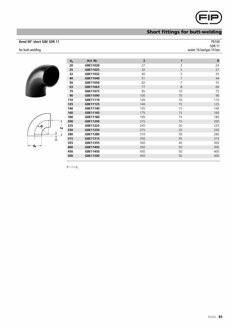
85
Short fittings for butt-welding
Bends
R � 1 x de
Bend 90° short GBE SDR 11 PE100SDR 11
for butt-welding water 16 bar/gas 10 bar
de Art. Nr. Z l R
20 GBE11020 27 3 24
25 GBE11025 32 5 27
32 GBE11032 40 5 35
40 GBE11040 51 7 44
50 GBE11050 62 7 55
63 GBE11063 77 8 69
75 GBE11075 85 10 75
90 GBE11090 100 10 90
110 GBE11110 120 10 110
125 GBE11125 140 15 125
140 GBE11140 155 15 140
160 GBE11160 175 15 160
180 GBE11180 195 15 180
200 GBE11200 215 15 200
225 GBE11225 245 20 225
250 GBE11250 275 25 250
280 GBE11280 310 30 280
315 GBE11315 350 35 315
355 GBE11355 340 40 300
400 GBE11400 350 50 300
450 GBE11450 450 50 400
500 GBE11500 450 50 400

86
-- to be continued --
Short fittings for butt-welding
Reducers
Reducer concentric DIN short RBE SDR 33 PE100SDR 33
for butt-welding water 3,2 bar
de1/de2 Art. Nr. L l1 l2
200/140 RBE33200140 154 50 35
200/160 RBE33200160 151 50 40
200/180 RBE33200180 151 50 45
225/140 RBE33225140 160 60 50
225/160 RBE33225160 171 55 40
225/180 RBE33225180 171 55 45
225/200 RBE33225200 171 55 50
250/160 RBE33250160 194 60 40
250/180 RBE33250180 182 60 45
250/200 RBE33250200 182 60 50
250/225 RBE33250225 182 60 55
280/200 RBE33280200 200 80 65
280/225 RBE33280225 200 80 75
280/250 RBE33280250 200 80 85
315/200 RBE33315200 230 95 85
315/225 RBE33315225 230 95 88
315/250 RBE33315250 230 95 95
315/280 RBE33315280 230 95 107
Reducer concentric DIN short RBE SDR 17 PE100SDR 17
for butt-welding water 10 bar/gas 5 bar
de1/de2 Art. Nr. L l1 l2
50/32 RBE17050032 55 12 12
50/40 RBE17050040 55 12 12
63/32 RBE17063032 65 16 12
63/40 RBE17063040 65 16 12
63/50 RBE17063050 65 16 12
75/32 RBE17075032 80 19 12
75/40 RBE17075040 71 19 12
75/50 RBE17075050 71 19 12
75/63 RBE17075063 71 19 16
90/50 RBE17090050 80 22 12
90/63 RBE17090063 80 22 16
90/75 RBE17090075 80 22 19
110/50 RBE17110050 105 28 12
110/63 RBE17110063 97 28 16
110/75 RBE17110075 97 28 19
110/90 RBE17110090 97 28 22
125/63 RBE17125063 112 30 16
125/75 RBE17125075 108 32 19
125/90 RBE17125090 108 32 22
125/110 RBE17125110 108 32 28
140/75 RBE17140075 123 35 19
140/90 RBE17140090 115 35 22
140/110 RBE17140110 115 35 28
140/125 RBE17140125 115 35 32
160/90 RBE17160090 135 40 22
160/110 RBE17160110 124 40 28
160/125 RBE17160125 124 40 32
160/140 RBE17160140 124 40 35

87
-- to be continued --
Reducer concentric DIN short RBE SDR 17 - continuation -
Short fittings for butt-welding
Reducers
180/90 RBE17180090 157 45 22
180/110 RBE17180110 157 45 28
180/125 RBE17180125 136 45 32
180/140 RBE17180140 136 45 35
180/160 RBE17180160 136 45 40
200/140 RBE17200140 154 50 35
200/160 RBE17200160 151 50 40
200/180 RBE17200180 151 50 45
225/140 RBE17225140 160 60 50
225/160 RBE17225160 171 55 40
225/180 RBE17225180 171 55 45
225/200 RBE17225200 171 55 50
250/160 RBE17250160 194 60 40
250/180 RBE17250180 182 60 45
250/200 RBE17250200 182 60 50
250/225 RBE17250225 182 60 55
280/200 RBE17280200 * 200 85 70
280/225 RBE17280225 * 200 85 72
280/250 RBE17280250 * 200 85 80
315/200 RBE17315200 * 230 95 85
315/225 RBE17315225 * 230 95 88
315/250 RBE17315250 * 230 95 95
315/280 RBE17315280 * 230 95 107
* machined version
de1/de2 Art. Nr. L l1 l2
Reducer concentric DIN short RBE SDR 11 PE100SDR 11
for butt-welding water 16 bar/gas 10 bar
de1/de2 Art. Nr. L l1 l2
25/20 RBE11025020 37 12 12
32/20 RBE11032020 43 12 12
32/25 RBE11032025 43 12 12
40/20 RBE11040020 50 12 12
40/25 RBE11040025 50 12 12
40/32 RBE11040032 50 12 12
50/25 RBE11050025 55 12 12
50/32 RBE11050032 55 12 12
50/40 RBE11050040 55 12 12
63/32 RBE11063032 65 16 12
63/40 RBE11063040 65 16 12
63/50 RBE11063050 65 16 12
75/32 RBE11075032 80 19 12
75/40 RBE11075040 71 19 12
75/50 RBE11075050 71 19 12
75/63 RBE11075063 71 19 16
90/50 RBE11090050 80 22 12
90/63 RBE11090063 80 22 16
90/75 RBE11090075 80 22 19
110/50 RBE11110050 105 28 12
110/63 RBE11110063 97 28 16
110/75 RBE11110075 97 28 19
110/90 RBE11110090 97 28 22
125/63 RBE11125063 112 30 16
125/75 RBE11125075 108 32 19
125/90 RBE11125090 108 32 22
125/110 RBE11125110 108 32 28
140/75 RBE11140075 123 35 19
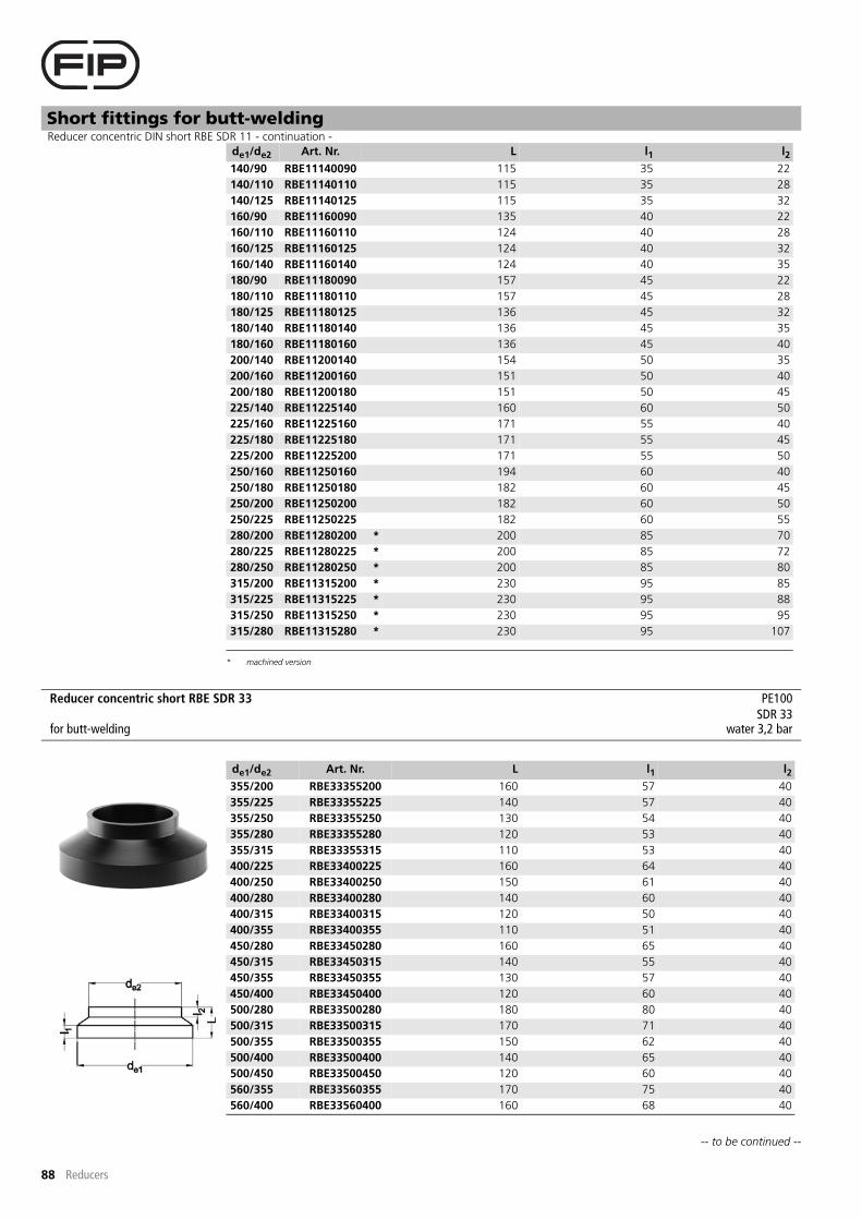
88
-- to be continued --
Reducer concentric DIN short RBE SDR 11 - continuation -
Short fittings for butt-welding
Reducers
140/90 RBE11140090 115 35 22
140/110 RBE11140110 115 35 28
140/125 RBE11140125 115 35 32
160/90 RBE11160090 135 40 22
160/110 RBE11160110 124 40 28
160/125 RBE11160125 124 40 32
160/140 RBE11160140 124 40 35
180/90 RBE11180090 157 45 22
180/110 RBE11180110 157 45 28
180/125 RBE11180125 136 45 32
180/140 RBE11180140 136 45 35
180/160 RBE11180160 136 45 40
200/140 RBE11200140 154 50 35
200/160 RBE11200160 151 50 40
200/180 RBE11200180 151 50 45
225/140 RBE11225140 160 60 50
225/160 RBE11225160 171 55 40
225/180 RBE11225180 171 55 45
225/200 RBE11225200 171 55 50
250/160 RBE11250160 194 60 40
250/180 RBE11250180 182 60 45
250/200 RBE11250200 182 60 50
250/225 RBE11250225 182 60 55
280/200 RBE11280200 * 200 85 70
280/225 RBE11280225 * 200 85 72
280/250 RBE11280250 * 200 85 80
315/200 RBE11315200 * 230 95 85
315/225 RBE11315225 * 230 95 88
315/250 RBE11315250 * 230 95 95
315/280 RBE11315280 * 230 95 107
* machined version
de1/de2 Art. Nr. L l1 l2
Reducer concentric short RBE SDR 33 PE100SDR 33
for butt-welding water 3,2 bar
de1/de2 Art. Nr. L l1 l2
355/200 RBE33355200 160 57 40
355/225 RBE33355225 140 57 40
355/250 RBE33355250 130 54 40
355/280 RBE33355280 120 53 40
355/315 RBE33355315 110 53 40
400/225 RBE33400225 160 64 40
400/250 RBE33400250 150 61 40
400/280 RBE33400280 140 60 40
400/315 RBE33400315 120 50 40
400/355 RBE33400355 110 51 40
450/280 RBE33450280 160 65 40
450/315 RBE33450315 140 55 40
450/355 RBE33450355 130 57 40
450/400 RBE33450400 120 60 40
500/280 RBE33500280 180 80 40
500/315 RBE33500315 170 71 40
500/355 RBE33500355 150 62 40
500/400 RBE33500400 140 65 40
500/450 RBE33500450 120 60 40
560/355 RBE33560355 170 75 40
560/400 RBE33560400 160 68 40

89
-- to be continued --
Reducer concentric short RBE SDR 33 - continuation -
Short fittings for butt-welding
Reducers
560/450 RBE33560450 140 62 40
560/500 RBE33560500 130 67 40
630/355 RBE33630355 200 80 40
630/400 RBE33630400 190 78 40
630/450 RBE33630450 170 72 40
630/500 RBE33630500 150 67 40
630/560 RBE33630560 130 64 40
710/500 RBE33710500 * 130 84 40
710/560 RBE33710560 * 170 81 40
710/630 RBE33710630 * 140 71 40
800/560 RBE33800560 * 200 85 40
800/630 RBE33800630 * 180 85 40
800/710 RBE33800710 * 150 78 40
900/630 RBE33900630 * 220 96 40
900/710 RBE33900710 * 190 89 40
900/800 RBE33900800 * 160 85 40
1000/710 RBE331000710 * 220 101 40
1000/800 RBE331000800 * 180 86 40
1000/900 RBE331000900 * 140 75 40
1200/1000 RBE3312001000 * 190 92 40
* fabrication on order, returning not possible
de1/de2 Art. Nr. L l1 l2
Reducer concentric short RBE SDR 17 PE100SDR 17
for butt-welding water 10 bar/gas 5 bar
de1/de2 Art. Nr. L l1 l2
355/200 RBE17355200 160 57 40
355/225 RBE17355225 140 57 40
355/250 RBE17355250 130 54 40
355/280 RBE17355280 120 53 40
355/315 RBE17355315 110 53 40
400/225 RBE17400225 160 64 40
400/250 RBE17400250 150 61 40
400/280 RBE17400280 140 60 40
400/315 RBE17400315 120 50 40
400/355 RBE17400355 110 51 40
450/280 RBE17450280 160 65 40
450/315 RBE17450315 140 55 40
450/355 RBE17450355 130 57 40
450/400 RBE17450400 120 60 40
500/280 RBE17500280 180 80 40
500/315 RBE17500315 170 71 40
500/355 RBE17500355 150 62 40
500/400 RBE17500400 140 65 40
500/450 RBE17500450 120 60 40
560/355 RBE17560355 170 75 40
560/400 RBE17560400 160 68 40
560/450 RBE17560450 140 62 40
560/500 RBE17560500 130 67 40
630/355 RBE17630355 200 80 40
630/400 RBE17630400 190 78 40
630/450 RBE17630450 170 72 40
630/500 RBE17630500 150 67 40
630/560 RBE17630560 130 64 40
710/500 RBE17710500 * 130 84 40
710/560 RBE17710560 * 170 81 40
710/630 RBE17710630 * 140 71 40

90
Reducer concentric short RBE SDR 17 - continuation -
Short fittings for butt-welding
Reducers
800/560 RBE17800560 * 200 85 40
800/630 RBE17800630 * 180 85 40
800/710 RBE17800710 * 150 78 40
900/630 RBE17900630 * 220 96 40
900/710 RBE17900710 * 190 89 40
900/800 RBE17900800 * 160 85 40
1000/710 RBE171000710 * 220 101 40
1000/800 RBE171000800 * 180 86 40
1000/900 RBE171000900 * 140 75 40
* fabrication on order, returning not possible
de1/de2 Art. Nr. L l1 l2
Reducer concentric short RBE SDR 11 PE100SDR 11
for butt-welding water 16 bar/gas 10 bar
de1/de2 Art. Nr. L l1 l2
355/200 RBE11355200 160 57 40
355/225 RBE11355225 140 57 40
355/250 RBE11355250 130 54 40
355/280 RBE11355280 120 53 40
355/315 RBE11355315 110 53 40
400/225 RBE11400225 160 64 40
400/250 RBE11400250 150 61 40
400/280 RBE11400280 140 60 40
400/315 RBE11400315 120 50 40
400/355 RBE11400355 110 51 40
450/280 RBE11450280 160 65 40
450/315 RBE11450315 140 55 40
450/355 RBE11450355 130 57 40
450/400 RBE11450400 120 60 40
500/280 RBE11500280 180 80 40
500/315 RBE11500315 170 71 40
500/355 RBE11500355 150 62 40
500/400 RBE11500400 140 65 40
500/450 RBE11500450 120 60 40
560/355 RBE11560355 170 75 40
560/400 RBE11560400 160 68 40
560/450 RBE11560450 140 62 40
560/500 RBE11560500 130 67 40
630/355 RBE11630355 200 80 40
630/400 RBE11630400 190 78 40
630/450 RBE11630450 170 72 40
630/500 RBE11630500 150 67 40
630/560 RBE11630560 130 64 40

91
Short fittings for butt-welding
Reducers
Larger diameters on request.
Reducer eccentric short REBE SDR 33 PE100SDR 33
for butt-welding water 3,2 bar
de1/de2 Art. Nr. L l1 l2
160/90 REBE33160090 140 54 40
160/110 REBE33160110 120 45 40
160/125 REBE33160125 110 44 40
160/140 REBE33160140 90 33 40
180/110 REBE33180110 140 54 40
180/125 REBE33180125 130 52 40
180/140 REBE33180140 110 41 40
180/160 REBE33180160 90 33 40
200/125 REBE33200125 150 61 40
200/140 REBE33200140 130 50 40
200/160 REBE33200160 110 41 40
200/180 REBE33200180 90 33 40
225/140 REBE33225140 160 65 40
225/160 REBE33225160 140 57 40
225/180 REBE33225180 120 48 40
225/200 REBE33225200 100 40 40
250/160 REBE33250160 160 62 40
250/180 REBE33250180 140 54 40
250/200 REBE33250200 120 45 40
250/225 REBE33250225 100 40 40
280/180 REBE33280180 170 66 40
280/200 REBE33280200 150 58 40
280/225 REBE33280225 130 52 40
280/250 REBE33280250 110 47 40
315/200 REBE33315200 190 78 40
315/225 REBE33315225 160 62 40
315/250 REBE33315250 140 57 40
315/280 REBE33315280 110 44 40

92
Short fittings for butt-welding
Reducers
Larger diameters on request.
Reducer eccentric short REBE SDR 17 PE100SDR 17
for butt-welding water 10 bar/gas 5 bar
de1/de2 Art. Nr. L l1 l2
160/90 REBE17160090 140 54 40
160/110 REBE17160110 120 45 40
160/125 REBE17160125 110 44 40
160/140 REBE17160140 90 33 40
180/110 REBE17180110 140 54 40
180/125 REBE17180125 130 52 40
180/140 REBE17180140 110 41 40
180/160 REBE17180160 90 33 40
200/125 REBE17200125 150 61 40
200/140 REBE17200140 130 50 40
200/160 REBE17200160 110 41 40
200/180 REBE17200180 100 43 40
225/140 REBE17225140 160 65 40
225/160 REBE17225160 140 57 40
225/180 REBE17225180 120 48 40
225/200 REBE17225200 100 40 40
250/160 REBE17250160 160 62 40
250/180 REBE17250180 140 54 40
250/200 REBE17250200 130 55 40
250/225 REBE17250225 100 40 40
280/180 REBE17280180 170 66 40
280/200 REBE17280200 150 58 40
280/225 REBE17280225 130 52 40
280/250 REBE17280250 110 47 40
315/200 REBE17315200 190 78 40
315/225 REBE17315225 160 62 40
315/250 REBE17315250 140 57 40
315/280 REBE17315280 120 54 40

93
Short fittings for butt-welding
Reducers
Larger diameters on request.
Reducer eccentric short REBE SDR 11 PE100SDR 11
for butt-welding water 16 bar/gas 10 bar
de1/de2 Art. Nr. L l1 l2
160/90 REBE11160090 140 54 40
160/110 REBE11160110 120 45 40
160/125 REBE11160125 110 44 40
160/140 REBE11160140 100 43 40
180/110 REBE11180110 140 54 40
180/125 REBE11180125 130 52 40
180/140 REBE11180140 120 51 40
180/160 REBE11180160 100 43 40
200/125 REBE11200125 150 61 40
200/140 REBE11200140 130 50 40
200/160 REBE11200160 120 51 40
200/180 REBE11200180 100 43 40
225/140 REBE11225140 160 65 40
225/160 REBE11225160 140 57 40
225/180 REBE11225180 120 48 40
225/200 REBE11225200 110 50 40
250/160 REBE11250160 170 72 40
250/180 REBE11250180 150 64 40
250/200 REBE11250200 130 55 40
250/225 REBE11250225 110 50 40
280/180 REBE11280180 180 76 40
280/200 REBE11280200 160 68 40
280/225 REBE11280225 140 62 40
280/250 REBE11280250 120 57 40
315/200 REBE11315200 190 78 40
315/225 REBE11315225 170 72 40
315/250 REBE11315250 150 67 40
315/280 REBE11315280 130 64 40

94
-- to be continued --
Short fittings for butt-welding
End caps
End cap long/short CBE SDR 17 PE100SDR 17
for butt-welding water 10 bar/gas 5 bar
de Art. Nr. L l
63 CDE17063 *
* long version
85 62
75 CDE17075 * 95 63
90 CDE17090 * 110 79
110 CDE17110 * 127 88
125 CDE17125 * 124 95
140 CDE17140 * 140 110
160 CDE17160 * 152 121
180 CDE17180 * 169 134
200 CDE17200 * 184 140
225 CDE17225 * 200 160
250 CDE17250 * 230 152
280 CDE17280 * 257 162
315 CDE17315 * 262 167
355 CDE17355 * 270 250
400 CDE17400 * 275 250
450 CBE17450 **
** short version, machinedfabrication on order, returning not possible
85 -
500 CBE17500 ** 90 -
560 CBE17560 ** 100 -
630 CBE17630 ** 110 -
710 CBE17710 ** 110 -
800 CBE17800 ** 120 -
End cap long/short CBE SDR 11 PE100SDR 11
for butt-welding water 16 bar/gas 10 bar
de Art. Nr. L l
20 CDE11020 * 45 35
25 CDE11025 * 52 40
32 CDE11032 * 58 44
40 CDE11040 * 67 50
50 CDE11050 * 75 55
63 CDE11063 * 85 62
75 CDE11075 * 95 63
90 CDE11090 * 110 79
110 CDE11110 * 127 88
125 CDE11125 * 124 95
140 CDE11140 * 140 110
160 CDE11160 * 152 121
180 CDE11180 * 169 134
200 CDE11200 * 184 140
225 CDE11225 * 200 160
250 CDE11250 * 230 152
280 CDE11280 * 257 162
315 CDE11315 * 262 167
355 CDE11355 * 280 250
400 CDE11400 * 285 250

95
End cap long/short CBE SDR 11 - continuation -
Short fittings for butt-welding
End caps
450 CBE11450 ** 95 -
500 CBE11500 ** 105 -
560 CBE11560 ** 115 -
630 CBE11630 ** 125 -
* long version
** short version, machinedfabrication on order, returning not possible
de Art. Nr. L l

96
Short fittings for butt-welding
Unions
Unions complete consist of:- PE union end and union bush- PVC nut- EPDM O-ring
Depending on temperature change the maximum operating pressure can be reduced strongly.
Unions complete consist of:- PE union end and union bush- PVC nut- FPM O-ring
Depending on temperature change the maximum operating pressure can be reduced strongly.Collectioning on order.
Union complete short BBE/C SDR 11 with EPDM O-ring PE100SDR 11
for butt-welding water 10 bar
de Art. Nr. L
20 BBEC11020E 110
25 BBEC11025E 110
32 BBEC11032E 110
40 BBEC11040E 110
50 BBEC11050E 110
63 BBEC11063E 110
75 BBEC11075E 110
90 BBEC11090E 180
110 BBEC11110E 180
Union complete short BBE/C SDR 11 with FPM O-ring PE100SDR 11
for butt-welding water 10 bar
de Art. Nr. L
20 BBEC11020F 110
25 BBEC11025F 110
32 BBEC11032F 110
40 BBEC11040F 110
50 BBEC11050F 110
63 BBEC11063F 110
75 BBEC11075F 110
90 BBEC11090F 180
110 BBEC11110F 180

97
Short fittings for butt-welding
Unions
Thread according to EN-ISO 228.
Union bush short F/BBE-C SDR 11 PE100SDR 11
for butt-welding
de Art. Nr. L l G
20 FBBEC11020 55 13 1"
25 FBBEC11025 55 13 1¼"
32 FBBEC11032 55 14 1½"
40 FBBEC11040 55 16 2"
50 FBBEC11050 55 18 2¼"
63 FBBEC11063 55 20 2¾"
75 FBBEC11075 55 24 3½"
90 FBBEC11090 90 25 4"
110 FBBEC11110 90 28 5"
Union end short Q/BBE-C SDR 11 PE100SDR 11
for butt-welding
de Art. Nr. L h d1 d2
20 QBBEC11020 55 5 27,4 30,0
25 QBBEC11025 55 6 35,9 38,5
32 QBBEC11032 55 6 41,4 44,5
40 QBBEC11040 55 7 52,8 56,2
50 QBBEC11050 55 7 58,8 62,2
63 QBBEC11063 55 8 73,8 78,3
75 QBBEC11075 55 9 82,5 96,5
90 QBBEC11090 90 10 97,5 109,5
110 QBBEC11110 90 11 117,5 134,5

98
Short fittings for butt-welding
Unions
Unions complete consist of:- PE union end and union bush- PVC nut- EPDM O-ring
Depending on temperature change the maximum operating pressure can be reduced strongly.
Unions complete consist of:- PE union end and union bush- PVC nut- FPM O-ring
Depending on temperature change the maximum operating pressure can be reduced strongly.
Collectioning on order.
Union complete long BBE/L SDR 11 with EPDM O-ring PE100SDR 11
for butt-welding and electrofusion water 10 bar
de Art. Nr. L
20 BBEL11020E 190
25 BBEL11025E 190
32 BBEL11032E 190
40 BBEL11040E 190
50 BBEL11050E 190
63 BBEL11063E 190
75 BBEL11075E 260
90 BBEL11090E 300
110 BBEL11110E 340
Union complete long BBE/L SDR 11 with FPM O-ring PE100SDR 11
for butt-welding and electrofusion water 10 bar
de Art. Nr. L
20 BBEL11020F 190
25 BBEL11025F 190
32 BBEL11032F 190
40 BBEL11040F 190
50 BBEL11050F 190
63 BBEL11063F 190
75 BBEL11075F 260
90 BBEL11090F 300
110 BBEL11110F 340

99
Short fittings for butt-welding
Unions
Thread according to EN-ISO 228.
Union bush long F/BBE-L SDR 11 PE100SDR 11
for butt-welding and electrofusion
de Art. Nr. L l G
20 FBBEL11020 95 13 1"
25 FBBEL11025 95 13 1¼"
32 FBBEL11032 95 14 1½"
40 FBBEL11040 95 16 2"
50 FBBEL11050 95 18 2¼"
63 FBBEL11063 95 20 2¾"
75 FBBEL11075 130 24 3½"
90 FBBEL11090 150 25 4"
110 FBBEL11110 170 28 5"
Union end long Q/BBE-L SDR 11 PE100SDR 11
for butt-welding and electrofusion
de Art. Nr. L h d1 d2
20 QBBEL11020 95 5 25,0 30,0
25 QBBEL11025 95 6 33,5 38,5
32 QBBEL11032 95 6 38,0 44,5
40 QBBEL11040 95 7 49,5 56,2
50 QBBEL11050 95 7 55,0 62,2
63 QBBEL11063 95 8 70,0 78,3
75 QBBEL11075 130 9 82,5 96,5
90 QBBEL11090 150 10 97,5 109,5
110 QBBEL11110 170 11 117,5 134,5

100
Short fittings for butt-welding
Unions
Thread according to EN-ISO 228.
Union nut EFV for PE union end PVC
de Art. Nr. D G d3 H
20 EFV100 43 1" 27 24
25 EFV114 53 1¼" 36 27
32 EFV112 60 1½" 41 30
40 EFV200 74 2" 53 32
50 EFV214 80 2¼" 59 36
63 EFV234 103 2¾" 74 39
75 EFV312 122 3½" 83 43
90 EFV400 139 4" 98 49
110 EFV500 164 5" 118 55
O-ring for PE union bush EPDM
de Art. Nr. d2 d3
20 OR4081E 20,22 3,53
25 OR4112E 28,17 3,53
32 OR4131E 32,93 3,53
40 OR6162E 40,65 5,34
50 OR6187E 47,00 5,34
63 OR6237E 59,69 5,34
75 OR6312E 78,80 5,30
90 OR6375E 94,60 5,30
110 Z481109000 113,70 7,00

101
Short fittings for butt-welding
Unions
O-ring for PE union bush FPM
de Art. Nr. d2 d3
20 OR4081F 20,22 3,53
25 OR4112F 28,17 3,53
32 OR4131F 32,93 3,53
40 OR6162F 40,65 5,34
50 OR6187F 47,00 5,34
63 OR6237F 59,69 5,34
75 OR6312F 78,80 5,30
90 OR6375F 94,60 5,30
110 Z481107000 113,70 7,00

102
Short fittings for butt-welding
Adaptors
SW = size of the jaw.Thread according to EN 10226 (ISO 7).For sealing we advise PTFE tape.Depending on assembly method and temperature change the maximum operating pressure can be reduced strongly.
SW = size of the jaw.Thread according to EN 10226 (ISO 7).For sealing we advise PTFE tape.Depending on assembly method and temperature change the maximum operating pressure can be reduced strongly. For specific applications please contact our Technical Support.
Adaptor long DBME SDR 11 with female thread PE100SDR 11
for butt-welding and electrofusion water 10 bar
de/Rp Art. Nr. L l D SW
20/½" DBME11020012 65 40 39 32
25/½" DBME11025012 65 40 39 32
25/¾" DBME11025034 66 40 49 41
32/½" DBME11032012 69 44 39 32
32/¾" DBME11032034 70 44 49 41
32/1" DBME11032100 72 44 55 46
40/¾" DBME11040034 69 45 49 41
40/1" DBME11040100 76 49 55 46
40/1¼" DBME11040114 80 49 66 55
50/½" DBME11050012 76 55 50 32
50/1" DBME11050100 78 50 55 46
50/1¼" DBME11050114 85 55 66 55
50/1½" DBME11050112 86 55 83 70
63/2" DBME11063200 100 63 94 85
Adaptor short SDR 11 with male thread PE100SDR 11
for butt-welding water 8 bar
de/R Art. Nr. L l1 l2 SW
20/½" KBFE11020012 46 19 18 22
25/¾" KBFE11025034 51 22 20 27
32/1" KBFE11032100 61 28 24 36
40/1¼" KBFE11040114 66 29 26 46
50/1½" KBFE11050112 74 32 28 55
63/2" KBFE11063200 80 35 31 65


