
Face mill type: 50 66 12 items Face mill fine pitch type: 50 80 14 items Heads type: 20 40 10 items Heads fine pitch type: 20 42 12 items
PRODUCTNEWSNo. 321
NEW PRODUCT
Super Diemaster
HDM/SDH
High efficient machining tools
RDGT-MOT type RDGT-MOE typeRDMW-MOT type
Facemill type
Insert
SDH Headstype
Pocket Milling Copy Milling Helical Interpolation
R HoningFor Titanium & InconelChamfer HoningFor Stainless Steel& SteelChamfer HoningFor Steel
Face Milling
DIJET INDUSTRIAL CO., LTD.

Super Diemaster
1
Maximum 68% stronger than conventional Diemaster insert. In
addition to conventional insert grades, adopted new tough grade
"JC8050" against chipping for unfavorable conditions.
R3.5 & R5 inserts A.R. 6
R6 & R8 inserts A.R. 8
Reduced cutting forces 21%
than conventional Diemaster.
R3.5
2.38 3.18 3.97 4.762
2.7 4.1 4.8 6
R5 R6 R8
NEW
SuperDiemaster
Diemaster
Increased the insert strength
Adopted double clamp system for deep cut applications.
Adopted GN surface-hardening treatment on thermal resistant high
strength steel gives high hardness over 65HRC and secure insert pocket
and holder against thermal deformation, improved body durability and
tool life by 30% or more. Make it difficult to be damaged even under
severe cutting conditions. Also rust-proof and anti-welding effect is
much improved.
Double clamp system
High efficient machining tool with edge sharp
Adopted positive axial rake Variation
Insert strength comparison
Increase68%
Strenght
Many kinds of modular heads are
available with combination of carbide
shank.
Feature of product

2
Super Diemaster Diemaster
pness and strengthAll tool has coolant holesfrom each pockets
Insert thickness 4.1 Insert thickness 3.18
SDH-2250-R10-M12RDMW1004MOT
MDH-2250-M12RDHX1003MOT
Insert Comparison

Super Diemaster
3
Cutting force comparison
Cutting performance
High feed machining for hardened die steel
Tool dia.:40mm dia., Mat’l:1.2344 45HRC
Vc=201m/min, fz=0.4mm/t ap=0.2mm,
ae=16mm by down cut
SDH-2400-R12-M16
RDMW1204MOT
SDH-2400-R12-M16
RDGT1204MOE
MDH-4400-M10
RDHX1203MOT
General machining for die steel
Tool dia.:40mm dia., Mat’l:1.2379 HS30
Vc=200m/min, fz=0.31mm/t ap=1.5mm,
ae=16mm by down cut
Shape and temperature of Chips
Shape and temperature of Chips
Low
High
Super Diemaster RDMW type
Diemaster
SDH-2400-R12-M16
RDMW1204MOT
SDH-2400-R12-M16
RDGT1204MOE
MDH-4400-M10
RDHX1203MOT
General machining for hardened die steel
Tool dia.:20mm dia., Mat’l:1.2344 45HRC
Vc=91m/min, fz=0.2mm/t ap=0.7mm,
ae=10mm by down cut
SDH-2200-R07-M10 RDMW07T2MOT
MDH-4200-M10 RDHX0702MOT
General machining for die steel
Tool dia.:20mm dia., Mat’l:1.2379 HS30
Vc=179m/min, fz=0.34 mm/t ap=1.2mm,
ae=10mm by down cut
SDH-2200-R07-M10 RDMW07T2MOT
MDH-4200-M10 RDHX0702MOT
Super Diemaster
Diemaster
X Feed force
Y Main force
ZBack force
Resultant
force
0
200
400
600
800
1,000
1,200
1,400
1,600
1,800
N
XFeed force
YMain force
ZBack force
Resultant
force
0
100
200
300
400
500
600
700
800
900
1,000
N
XFeed force
YMain force
ZBack force
Resultant
forceX
Feed force
YMain force
ZBack force
Resultant
force
0
200
400
600
800
1,000
1,200
1,400
1,600
1,800
2,000N
21% REDUCEDCutting Forces
18% REDUCEDCutting Forces
RDMW type 21% REDUCED
RDGT type 31% REDUCED
RDMW type 14% REDUCED
RDGT type 29% REDUCED
Super Diemaster RDGT type
Low
High

4
Tool life comparison
High feed machining for hardened die steel
Tool dia: 20mm, Mat’l:1.2344,43HRC, Overhung length:70mm Vc=250m/min, fz=0.2mm/t, ap=0.2mm, ae=10mm
(Air blow by down cutting) MSN-M10-40-S20C + each cutter
Damaged condition of inserts
After 72m After 122.4m After 165.6m
RDMW07T2MOT JC8015
VB MAX flank wear mm
RDHX07T2MOS JC5003VB MAX flank wear mm
0.154
0.134 0.356
0.237
High feed machining for hardened die steel
Tool dia:25mm, Mat’l:1.2379,43HRC, Overhung length:70mm Vc=250m/min, fz=0.3mm/t, ap=0.2mm, ae=15.5mm
(Air blow by down cutting) MSN-M12-55-S25C+each cutter
Damaged condition of inserts
After 72m After 86.2m
RDMW1004MOT JC8015VB MAX flank wear mm
Competitor Y
RDHX1003MOT TiAINVB MAXflank wear mm
RDHX1003MOS JC5003VB MAX flank wear mm
Ti-alloy age hardened
Tool dia:32mm, Mat’l:Ti6Al4V,42HRC, Overhung length:118mm Vc=60m/min, fz=0.3mm/t, ap=0.5mm, ae=12mm
(Wet cutting by down cutting) MSN-M16-157S-S32C + SDH-2320-R12-M16
Damaged condition of inserts
After 1.32m After 10.56m After 17.16m
RDGT1204MOE JC8015VB MAX flank wear mm
0.075 0.104 0.124
0 5 10 15 200
0.1
0.2
0.3
RDGT1204MOE/JC8015
0 10 20 30 40 50 60 70 80 90 1000
0.1
0.2
0.3
0.4
0.5
0.6
0.7
Cutting length m
Ma
x.
fla
nk w
ea
rm
m
SDH-2250-R10-M12
RDMW1004MOT/JC8015
Competitor Y
RDHX1003MOT/TiAIN
MDH-2250-M12
RDHX1003MOS/JC5003
00 50 100 150 200
Cutting length m
0.1
0.2
0.3
0.4
0.5
Ma
x.
fla
nk w
ea
rm
m
SDH-2200-R07-M10
RDMW07T2MOT/JC8015
MDH-4200-M10
RDHX07T2MOS/JC5003
Ma
x.
fla
nk w
ea
rm
m
Cutting length m

Standard stock items Note) 1.All cutters are supplied without inserts.
2 Please see page 13-14 for cutting conditions.
5
Line up
Facemill type (standard type)
Cat. No.
Dimensions
No. ofinserts
3
3
4
4
4
4
4
4
3
3
4
4
50
50
63
63
80
80
80
80
50
50
63
63
6
8
6
8
6
6
8
8
6
8
6
8
50
55
50
50
55
70
55
70
50
55
50
50
47
47
60
60
60
74
60
76
47
47
60
60
22.225
22.225
22.225
22.225
25.4
31.75
25.4
31.75
22
22
22
22
16.5
16.5
16.5
16.5
20
26
20
26
16.5
16.5
16.5
16.5
8.4
8.4
8.4
8.4
9.5
12.7
9.5
12.7
10.4
10.4
10.4
10.4
5
5
5
5
6
8
6
8
6.3
6.3
6.3
6.3
20
20
20
20
24
32
24
32
20
20
20
20
RD**1204M0*
RD**1606M0*
RD**1204M0*
RD**1606M0*
RD**1204M0*
RD**1204M0*
RD**1606M0*
RD**1606M0*
RD**1204M0*
RD**1606M0*
RD**1204M0*
RD**1606M0*
DSW-4085
DSW-4512H
DSW-4085
DSW-4512H
DSW-4085
DSW-4085
DSW-4512H
DSW-4512H
DSW-4085
DSW-4512H
DSW-4085
DSW-4512H
DCM-18
DCM-17
DCM-18
DCM-17
DCM-18
DCM-18
DCM-17
DCM-17
DCM-18
DCM-17
DCM-18
DCM-17
A-15T
A-20
A-15T
A-20
A-15T
A-15T
A-20
A-20
A-15T
A-20
A-15T
A-20
Clamp screw Clamp set Wrench
Inserts
HDM-3050-12R
HDM-3050-16R
HDM-4063-12R
HDM-4063-16R
HDM-4080-12R-25.4
HDM-4080-12R
HDM-4080-16R-25.4
HDM-4080-16R
HDM-3050-12R-22
HDM-3050-16R-22
HDM-4063-12R-22
HDM-4063-16R-22
Metr
ic B
ore
Inch
Bo
reTy
pe
Stock
Dc Lf Db d d1 a bR
Parts
Through coolant hole
Double clamp
Dc
d1R
Lf
b
a
d
Db
Super Diemaster

6
RD**1606M0*
RD**1204M0*
RD**1606M0*
RD**1204M0*
RD**1606M0*
RD**1204M0*
RD**1606M0*
RD**1204M0*
RD**1606M0*
RD**1204M0*
RD**1606M0*
RD**1204M0*
RD**1606M0*
RD**1204M0*
Facemill type (fine pitch)
4
5
5
6
4
5
4
5
5
6
5
6
6
7
50
50
63
63
50
50
52
52
63
63
66
66
80
80
8
6
8
6
8
6
8
6
8
6
8
6
8
6
55
50
50
50
55
50
55
50
50
50
50
50
55
55
47
47
60
60
47
47
47
47
60
60
60
60
76
76
22.225
22.225
22.225
22.225
22
22
22
22
27
27
27
27
27
27
16.5
16.5
16.5
16.5
16.5
16.5
16.5
16.5
20
20
20
20
20
20
8.4
8.4
8.4
8.4
10.4
10.4
10.4
10.4
12.4
12.4
12.4
12.4
12.4
12.4
5
5
5
5
6.3
6.3
6.3
6.3
7
7
7
7
7
7
20
20
20
20
20
20
20
20
22
22
22
22
22
22
DSW-4512H
DSW-4085
DSW-4512H
DSW-4085
DSW-4512H
DSW-4085
DSW-4512H
DSW-4085
DSW-4512H
DSW-4085
DSW-4512H
DSW-4085
DSW-4512H
DSW-4085
A-20
A-15T
A-20
A-15T
A-20
A-15T
A-20
A-15T
A-20
A-15T
A-20
A-15T
A-20
A-15T
HDM-4050-16R
HDM-5050-12R
HDM-5063-16R
HDM-6063-12R
HDM-4050-16R-22
HDM-5050-12R-22
HDM-4052-16R-22
HDM-5052-12R-22
HDM-5063-16R-27
HDM-6063-12R-27
HDM-5066-16R-27
HDM-6066-12R-27
HDM-6080-16R-27
HDM-7080-12R-27
Dc Lf Db d d1 a bR
Through coolant hole
Db
d
a
b
Lf
R
Dc
d1
Standard stock items; Soon to be stocked
Note) 1.All cutters are supplied without inserts.
2 Please see page 13-14 for cutting conditions.
Cat. No.
Dimensions
No. ofinserts
Clamp screw Wrench
Inserts
Metr
ic B
ore
Inch
Bo
reTy
pe
Stock
Parts

7
SDH heads type (fine pitch type)
Through coolant hole
Standard stock items
Note) 1. All cutters are supplied without inserts.
2. Please see page 17-19 for cutting conditions. 3. In case of machining perpendicular wall, shank clearance of combination 1 is small, so we recommend to use 3 heads.
Cat. No.
Dimensions
No. ofinserts
3
3
3
3
3
3
4
4
3
4
4
5
20
22
25
25
28
30
30
32
35
35
40
42
3.5
3.5
3.5
5
5
5
5
5
6
5
6
5
30
30
35
35
35
43
43
43
43
43
43
43
18
20
23
23
25
28
28
28
32
32
32
32
M10
M10
M12
M12
M12
M16
M16
M16
M16
M16
M16
M16
14
14
17
17
17
22
22
22
22
22
26
26
Clamp screw Wrench
A-08SD
A-08SD
A-08SD
A-15
A-15
A-15
A-15
A-15
A-15
A-15
A-15
A-15
Inserts
SDH-3200-R07-M10 1
SDH-3220-R07-M10 3
SDH-3250-R07-M12
SDH-3250-R10-M12
SDH-3280-R10-M12
SDH-3300-R10-M16
SDH-4300-R10-M16
SDH-4320-R10-M16
SDH-3350-R12-M16
SDH-4350-R10-M16
SDH-4400-R12-M16
SDH-5420-R10-M16
Stock
Dc Lf Db MD WR
Parts
TSW-2556H
TSW-2556H
TSW-2556H
CSW-408H
CSW-408H
CSW-408H
CSW-408H
CSW-408H
DSW-4085
CSW-408H
DSW-4085
CSW-408H
RD**07T2M0*
RD**07T2M0*
RD**07T2M0*
RD**1004M0*
RD**1004M0*
RD**1004M0*
RD**1004M0*
RD**1004M0*
RD**1204M0*
RD**1004M0*
RD**1204M0*
RD**1004M0*
Db
RW
MD
Dc
Lf
SDH heads type (standard type)
Standard stock items
Note) 1. All cutters are supplied without inserts.
2. Please see page 17-19 for cutting conditions. 3. In case of machining perpendicular wall, shank clearance of combination 1 is small, so we recommend to use 3 heads.
Cat. No.
Dimensions
No. ofinserts
2
2
2
2
2
2
3
2
3
2
20
22
25
28
30
32
32
35
35
40
3.5
3.5
5
5
5
6
5
6
5
6
30
30
35
35
43
43
43
43
43
43
18
20
23
25
28
28
28
32
32
32
M10
M10
M12
M12
M16
M16
M16
M16
M16
M16
14
14
17
17
22
22
22
22
22
26
TSW-2556H
TSW-2556H
CSW-408H
CSW-408H
CSW-408H
DSW-4085
CSW-408H
DSW-4085
CSW-408H
DSW-4085
DCM-18
DCM-18
DCM-18
DCM-18
DCM-18
DCM-18
DCM-18
DCM-18
A-08SD
A-08SD
A-15
A-15
A-15
A-15
A-15
A-15
A-15
A-15
1
1
2
2
2
2
2
2
2
2
Clamp screw Clamp set WrenchInserts
RD**07T2M0*
RD**07T2M0*
RD**1004M0*
RD**1004M0*
RD**1004M0*
RD**1204M0*
RD**1004M0*
RD**1204M0*
RD**1004M0*
RD**1204M0*
SDH-2200-R07-M10 1
SDH-2220-R07-M10 3
SDH-2250-R10-M12
SDH-2280-R10-M12
SDH-2300-R10-M16
SDH-2320-R12-M16
SDH-3320-R10-M16
SDH-2350-R12-M16
SDH-3350-R10-M16
SDH-2400-R12-M16
Stock Fig.Dc Lf Db MD WR
Parts
Through coolant hole
Dc
Lf
Db
RW
MD
W
Dc
Lf
Db
R
MD
Fig.1
Fig.2
Super Diemaster


MSN Carbide shank holder (Through coolant hole)
Cat. No.
Dimensions
End mill shank type Straight arbor type
Standard stock items
StockDs L D1 MD n
Fig.l1
For high productivity
Through coolant hole
Ds
L
D1
1
Cat. No.
Dimensions
Standard stock items
StockDs MDL
L
Ds
Note) In case of machining perpendicular wall, shank clearance of combination 1 (page7) and 2 is small,
so we recommend to use 3 (page7) heads.
Fig.1
Fig.2
20
40
40
90
90
140
140
25
55
105
155
25
55
105
155
195
80
100
100
150
150
200
200
90
120
170
220
90
120
170
220
260
M10
M12
M16
19.5
24
29
20
25
32
1
2
1
2
1
2
1
1
0 29
0 17
0 12
MSN-M10- 20 -S20C 2
MSN-M10- 40 -S20C 2
MSN-M10-40T-S20C
MSN-M10- 90 -S20C 2
MSN-M10-90T-S20C
MSN-M10-140-S20C 2
MSN-M10-140T-S20C
MSN-M12- 25 -S25C
MSN-M12- 55 -S25C
MSN-M12-105-S25C
MSN-M12-155-S25C
MSN-M16- 25 -S32C
MSN-M16- 55 -S32C
MSN-M16-105-S32C
MSN-M16-155-S32C
MSN-M16-195-S32C
18
20
23
25
28
32
130
190
130
190
250
185
265
145
215
285
160
230
310
157
217
287
357
M10
M10
M12
M12
M16
M16
MSN-M10-130S-S18C
MSN-M10-190S-S18C
MSN-M10-130S-S20C
MSN-M10-190S-S20C
MSN-M10-250S-S20C
MSN-M12-185S-S23C
MSN-M12-265S-S23C
MSN-M12-145S-S25C
MSN-M12-215S-S25C
MSN-M12-285S-S25C
MSN-M16-160S-S28C
MSN-M16-230S-S28C
MSN-M16-310S-S28C
MSN-M16-157S-S32C
MSN-M16-217S-S32C
MSN-M16-287S-S32C
MSN-M16-357S-S32C
NEW
NEW
NEW
9
Super Diemaster
n
D1
Ds
L
1

10
Cutting data
Carbon Steel Forgings for General Use
Result
Because of chipping by interrupted cutting,
competitor could cut 4 pcs only, but SUPER
DIEMASTER could cut 30 pcs. And, shortened the
machining time by 25%.
Result
Semi-finishing. After cutting 100 works, insert
showed less wear and lower cutting noise than
competitor.
Semi-finishing for stainless steel
Part name
Material
Hardness
Tool No.
Insert No.
ap
ae
Coolant
Machine
Parts
700
290 325HB
HDM-3050-16R
RDMW1606MOT JC8015
OIL
Vertical MC
Work
Tool
Cutting conditions
800
200
200
0.25
0.2
20-30
min-1
m/min
mm/min
mm /rev
mm
mm
n
Vc
Vf
f
Cutting speed
Feed speed
Part name
Material
Hardness
Tool No.
Insert No.
ap
ae
Coolant
Machine
Work
Tool
Cutting conditions
n
Vc
Vf
f
Cutting speed
Feed speed
Turbine Blades
Stainless steel SUS420
280HB
SDH-2200-R07-M10
RDMW07T2MOT JC8015
WET
Vertical MC
3,200
200
1,920
0.3
0.3
0.5
min-1
m/min
mm/min
mm /rev
mm
mm

800 1,300mm
1,000200 mm
Result
DDM inserts were broken on machining welding part, but HDM could cut without chatter and breakage problem due to increased insert strength. Also improved tool life from 20 min. to 30 min. 1.5 times better.
Result
HDM reduced machining time 20% and improved
tool life 1.3 times compared with competitors.
Vf was increased from 1,100 mm/min to 1,400
mm/min.
Part name
Material
Hardness
Tool No.
Insert No.
ap
ae
Coolant
Machine
Work
Tool
Cutting conditions
n
Vc
Vf
f
Cutting speed
Feed speed
11
Cutting for welding part
Cutting for die casting mold
Part name
Material
Hardness
Tool No.
Insert No.
ap
ae
Coolant
Machine
Work
Tool
Cutting conditions
n
Vc
Vf
f
Cutting speed
Feed speed
Cam
SKD11 Welding
62HRC
HDM-3050-16R
RDMW1606MOT JC8015
Dry
Vertical MC 22KW
1,000
157
500
0.5
1
27
min-1
m/min
mm/min
mm /rev
mm
mm
Die casting mold
SKT4
36-42HRC
HDM-4080-12R
RDMW1204MOT JC8015
Dry
Vertical MC
450
115
1,400
3
1.5 2.0
50
min-1
m/min
mm/min
mm /rev
mm
mm
Super Diemaster
Insert thickness
6.0 mm.
Conventional tool
Insert thickness
4.76 mm.
Super Diemaster

12
Ramping
Attention for profile milling
Dh
To
ol d
ia.
Dc
dc
Z
L
ap
D1
Dc
X
Helical interpolation
Calculation of tool pass dia. Depth of cut per one circuit should not exceed max. depth of cut ap.
Down cutting is recommended, so tool pass rotation should be counterclockwise.
Do not continue ramping after drilling.
dc Dh DcTool pass dia. Bore dia. Tool dia.
In case of ramping and helical interpolation, apply 70% or less feed speed from standard cutting condition table.
In case of drilling, apply 50% or less Z axis feed speed from standard cutting condition table.
Long consecutive chips may come out in case of drilling, confirm the safe condition sufficiently.
Tool dia. Insert dia.
D1Eff. Cutting dia.
(mm)
Dh minMin. bore dia.
(mm)
Dh maxMax. bore dia.
(mm)
Max. rampingangle
ap
Max. depthof cut (mm)
ap /L mmTotal cutting length at
Max. ap
ZMax. drillingdepth (mm)
XDepth of
holder face(mm)
20
22
25
25
28
30
32
32
35
35
40
42
50
50
52
52
63
63
66
66
80
80
13
15
18
15
18
20
22
20
25
23
28
32
38
34
40
36
51
47
54
50
68
64
30
34
40
34
40
44
48
44
54
50
60
68
80
75
84
79
106
101
112
107
140
135
38
42
48
48
54
58
62
62
68
68
78
82
98
98
102
102
124
124
130
130
158
158
5 30
4 35
3 40
10 45
8 20
7 15
6 25
7 35
5 30
6 15
4 55
4 05
5 15
7 25
4 55
6 55
3 45
5 00
3 30
4 40
2 45
3 30
3.5
3.5
3.5
5.0
5.0
5.0
5.0
6.0
5.0
6.0
6.0
5.0
6.0
8.0
6.0
8.0
6.0
8.0
6.0
8.0
6.0
8.0
36.3
43.6
54.6
26.3
34.1
39.3
44.4
45.1
51.9
54.7
69.7
70.0
65.2
61.4
69.7
65.9
91.5
91.4
98.1
98.0
124.9
130.7
1.5
1.5
1.5
2.5
2.5
2.5
2.5
2.5
2.5
2.5
2.5
2.5
3.5
4.0
3.5
4.0
3.5
4.0
3.5
4.0
3.5
4.0
2.5
2.5
2.5
3.5
3.5
3.5
3.5
3.5
3.5
3.5
3.5
3.5
4.5
5.0
4.5
5.0
4.5
5.0
4.5
5.0
4.5
5.0
7 R3.5
7 R3.5
7 R3.5
10 5
10 5
10 5
10 5
12 6
10 5
12 6
12 6
10 5
12 6
16 8
12 6
16 8
12 6
16 8
12 6
16 8
12 6
16 8

13
Tool dia. [insert type]
JC5040
JC8015
JC5040
JC8015
JC8015
JC8050
JC8015
JC8050
JC8015
JC8050
JC8015
Carbon steel(C50,C55)
Below 250HB
Die steel(1.2344,1.2379)Below 255HB
Stainless steelBelow 250HB
Hardeneddie steel
(1.2344,1.2379)40-50HRC
Grey & Nodular cast iron
(GG, GGG)Below 300HB
Titanium alloy35-43HRC
Inconel35-43HRC
Mold steel(1.2311,P20)30-43HRC
50 R6
No. of teeth 3N Double clamp No. of teeth 3N Double clamp No. of teeth 4N Double clamp
50 R8 63 R6Work materials Grades
Lmm
ap
mmVf
mm/minn
min-1L
mmap
mmVf
mm/minn
min-1L
mmap
mmVf
mm/minn
min-1
L:Overhung length ap :Depth of cut n :Spindle speed Vf: Feed speed
JC5040
JC8015
( )JC8015above 40HRC
Note:
1. The figure to be adjusted according to the machine rigidity or work rigidity.
2. In case of chatter occurring, recommend to reduce the depth of cut ap or Spindle speed and keep feed per tooth.
3. If machine does not have enough power, recommend to reduce the depth of cut ap or Spindle speed and Feed speed.
4. Use air blow.
5. In case of 50-55HRC, recommend to reduce 30% above ap, n, V f. (In the case of hardened die steel)
6. In case of titanium alloy or inconel, recommended wet cutting.
Facemill type (standard type)1/ 2
JC8015without
chipbreaker
JC8003above 50HRC
Super Diemaster
150
200
250
300
350
400
150
200
250
300
350
400
150
200
250
300
350
400
150
200
250
300
350
400
100
150
200
250
300
350
150
200
250
300
350
400
150
200
250
300
350
400
150
200
250
300
350
400
3
2.5
2
1.2
0.7
2.5
2
1.1
0.9
0.5
3
2.5
2
1.2
0.7
3
2.5
2
1.2
0.7
1.5
1.2
1
0.8
0.4
3
2.5
2
1.2
0.7
1
0.8
0.6
0.4
0.2
1
0.8
0.6
0.4
0.2
1,250
1,250
880
880
750
1,200
1,200
840
840
720
1,180
1,180
830
830
700
990
990
690
690
590
810
810
570
570
490
1,120
1,120
780
780
670
420
420
290
290
250
210
210
150
150
130
1,090
1,160
870
1,130
950
1,190
1,220
1,130
1,260
1,180
1,030
1,130
840
1,000
950
860
890
700
860
820
560
610
410
510
440
1,170
1,110
960
1,170
920
270
315
260
305
375
135
155
135
160
195
150
200
250
300
350
400
150
200
250
300
350
400
150
200
250
300
350
400
150
200
250
300
350
400
100
150
200
250
300
350
150
200
250
300
350
400
150
200
250
300
350
400
150
200
250
300
350
400
4
3
2
1.5
1
3.5
3
2.5
2
1
4
3
2
1.5
1
4
3
2
1.5
1
2
1.8
1.6
1.2
0.8
4
3
2
1.5
1
1.5
1.2
1
0.8
0.4
1.5
1.2
1
0.8
0.4
1,260
1,260
880
880
760
1,210
1,210
850
850
730
1,200
1,200
840
840
720
1,000
1,000
700
700
600
860
860
600
600
520
1,130
1,130
790
790
680
440
440
310
310
260
220
220
150
150
130
1,100
1,210
980
1,160
1,000
1,010
1,100
940
970
1,110
1,040
1,180
960
1,100
950
870
990
780
920
790
590
620
470
520
465
1,190
1,290
1,060
1,300
900
330
265
205
230
255
145
165
115
130
155
150
200
250
300
350
400
150
200
250
300
350
400
150
200
250
300
350
400
150
200
250
300
350
400
100
150
200
250
300
350
150
200
250
300
350
400
150
200
250
300
350
400
150
200
250
300
350
400
3
2.7
2.2
1.6
1
0.5
2.5
2.2
1.6
1.1
0.7
0.5
3
2.7
2.2
1.6
1
0.5
3
2.7
2.2
1.6
1
0.5
1.5
1.2
1
0.8
0.6
0.3
3
2.7
2.2
1.6
1
0.5
1
0.9
0.7
0.5
0.3
0.2
1
0.9
0.7
0.5
0.3
0.2
980
980
690
690
590
540
940
940
660
660
560
520
930
930
650
650
560
510
780
780
550
550
470
430
650
650
450
450
390
360
880
880
620
620
530
480
330
330
230
230
200
180
165
165
120
120
100
90
1,140
1,300
910
1,100
1,010
1,190
1,160
1,240
970
1,180
1,120
1,140
1,080
1,120
850
1,040
870
1,100
900
930
730
830
690
940
580
650
490
520
590
620
1,370
1,440
1,120
1,240
1,160
1,220
260
290
240
295
340
360
130
160
130
150
165
180
Recommended cutting conditions

14
Note:
1. The figure to be adjusted according to the machine rigidity or work rigidity.
2. In case of chatter occurring, recommend to reduce the depth of cut ap or Spindle speed and keep feed per tooth.
3. If machine does not have enough power, recommend to reduce the depth of cut ap or Spindle speed and Feed speed.
4. Use air blow.
5. In case of 50-55HRC, recommend to reduce 30% above ap, n, V f. (In the case of hardened die steel)
6. In case of titanium alloy or inconel, recommended wet cutting.
Tool dia. [insert type]
63 R8
No. of teeth 4N Double clamp No. of teeth 4N Double clamp No. of teeth 4N Double clamp
80 R6 80 R8
Lmm
ap
mmVf
mm/minn
min-1L
mmap
mmVf
mm/minn
min-1L
mmap
mmVf
mm/minn
min-1
L:Overhung length ap :Depth of cut n :Spindle speed Vf: Feed speed
2/2
JC5040
JC8015
JC5040
JC8015
JC8015
JC8050
JC8015
JC8050
JC8015
JC8050
JC8015
Carbon steel(C50,C55)
Below 250HB
Die steel(1.2344,1.2379)Below 255HB
Stainless steelBelow 250HB
Hardeneddie steel
(1.2344,1.2379)40-50HRC
Grey & Nodular cast iron
(GG, GGG)Below 300HB
Titanium alloy35-43HRC
Inconel35-43HRC
Mold steel(1.2311,P20)30-43HRC
Work materials Grades
JC8015without
chipbreaker
JC8003above 50HRC
JC5040
JC8015
( )JC8015above 40HRC
Facemill type (standard type)
150
200
250
300
350
400
150
200
250
300
350
400
150
200
250
300
350
400
150
200
250
300
350
400
100
150
200
250
300
350
150
200
250
300
350
400
150
200
250
300
350
400
150
200
250
300
350
400
4
3
2
1.5
1
0.5
3.5
3
2.5
2
1
0.5
4
3
2
1.5
1
0.5
4
3
2
1.5
1
0.5
2
1.8
1.6
1.2
0.8
0.4
4
3
2
1.5
1
0.5
1.5
1.3
1.1
0.9
0.6
0.3
1.5
1.3
1.1
0.9
0.6
0.3
990
990
690
690
590
540
950
950
670
670
570
520
940
940
660
660
560
520
790
790
550
550
470
430
660
660
460
460
400
370
890
890
620
620
530
490
340
340
240
240
200
190
170
170
120
120
100
95
1,110
1,290
1,200
1,210
1,040
1,360
1,140
1,250
980
1,020
1,000
1,330
1,090
1,240
970
1,160
980
1,330
920
1,040
850
960
800
1,100
600
610
460
500
530
470
1,240
1,350
1,140
1,310
1,180
1,250
300
325
240
250
290
300
170
155
120
130
140
180
150
200
250
300
350
400
150
200
250
300
350
400
150
200
250
300
350
400
150
200
250
300
350
400
100
150
200
250
300
350
150
200
250
300
350
400
150
200
250
300
350
400
150
200
250
300
350
400
3
2.7
2.2
1.6
1
0.5
2.5
2.2
1.6
1.1
0.7
0.5
3
2.7
2.2
1.6
1
0.5
3
2.7
2.2
1.6
1
0.5
1.5
1.2
1
0.8
0.6
0.3
3
2.7
2.2
1.6
1
0.5
1
0.9
0.7
0.5
0.3
0.2
1
0.9
0.7
0.5
0.3
0.2
770
770
540
540
460
420
740
740
520
520
440
410
730
730
510
510
440
400
610
610
430
430
370
340
500
500
350
350
300
280
690
690
480
480
410
380
250
250
180
180
150
140
125
125
90
90
75
70
890
980
710
820
700
920
780
970
680
930
880
900
820
900
670
750
670
900
710
750
560
650
540
740
480
500
380
420
460
390
970
1,020
730
820
780
830
200
240
190
230
250
280
100
115
100
115
130
140
150
200
250
300
350
400
150
200
250
300
350
400
150
200
250
300
350
400
150
200
250
300
350
400
100
150
200
250
300
350
150
200
250
300
350
400
150
200
250
300
350
400
150
200
250
300
350
400
4
3
2
1.5
1
0.5
3.5
3
2.5
2
1
0.5
4
3
2
1.5
1
0.5
4
3
2
1.5
1
0.5
2
1.8
1.6
1.2
0.8
0.4
4
3
2
1.5
1
0.5
1.5
1.3
1.1
0.9
0.6
0.3
1.5
1.3
1.1
0.9
0.6
0.3
780
780
550
550
470
430
740
740
520
520
440
410
740
740
520
520
440
410
610
610
430
430
370
340
510
510
360
360
310
280
700
700
490
490
420
390
260
260
180
180
160
140
130
130
90
90
80
70
870
990
830
960
810
1,080
890
970
730
770
960
1,050
830
970
770
910
770
1,050
710
800
630
750
630
870
470
490
380
390
400
380
980
1,060
900
1,010
920
1,000
260
200
170
190
215
250
130
120
90
85
105
125

15
Facemill type (fine pitch)
50 / 52 R6
No. of teeth 5N No. of teeth 4N No. of teeth 6N
50 / 52 R8 63 / 66 R6 63 / 66 R8
No. of teeth 5N
Lmm
ap
mmVf
mm/minn
min-1L
mmap
mmVf
mm/minn
min-1L
mmap
mmVf
mm/minn
min-1L
mmap
mmVf
mm/minn
min-1
1/ 1
Super Diemaster
Recommended cutting conditions
Tool dia. [insert type]
JC5040
JC8015
JC5040
JC8015
JC8015
JC8050
JC8015
JC8050
JC8015
JC8050
JC8015
Carbon steel(C50,C55)
Below 250HB
Die steel(1.2344,1.2379)Below 255HB
Stainless steelBelow 250HB
Hardeneddie steel
(1.2344,1.2379)40-50HRC
Grey & Nodular cast iron
(GG, GGG)Below 300HB
Titanium alloy35-43HRC
Inconel35-43HRC
Mold steel(1.2311,P20)30-43HRC
Work materials Grades
L:Overhung length ap :Depth of cut n :Spindle speed Vf: Feed speed
JC5040
JC8015
( )JC8015above 40HRC
Note:
1. The figure to be adjusted according to the machine rigidity or work rigidity.
2. In case of chatter occurring, recommend to reduce the depth of cut ap or Spindle speed and keep feed per tooth.
3. If machine does not have enough power, recommend to reduce the depth of cut ap or Spindle speed and Feed speed.
4. Use air blow.
5. In case of 50-55HRC, recommend to reduce 30% above ap, n, V f. (In the case of hardened die steel)
6. In case of titanium alloy or inconel, recommended wet cutting.
JC8015without
chipbreaker
JC8003above 50HRC
150
200
250
300
350
400
150
200
250
300
350
400
150
200
250
300
350
400
150
200
250
300
350
400
100
150
200
250
300
350
150
200
250
300
350
400
150
200
250
300
350
400
150
200
250
300
350
400
2
1.7
1.5
1
0.5
1.7
1.5
1.2
0.8
0.4
1.7
1.5
1.2
0.8
0.4
2
1.7
1.5
1
0.5
1.2
1
0.8
0.5
0.3
2
1.7
1.5
1
0.5
1
0.8
0.6
0.4
0.2
1
0.8
0.6
0.4
0.2
150
200
250
300
350
400
150
200
250
300
350
400
150
200
250
300
350
400
150
200
250
300
350
400
100
150
200
250
300
350
150
200
250
300
350
400
150
200
250
300
350
400
150
200
250
300
350
400
3
2.5
2
1.2
0.7
2.5
2
1.1
0.9
0.5
2.5
2
1.1
0.9
0.5
3
2.5
2
1.2
0.7
1.5
1.2
1
0.8
0.4
3
2.5
2
1.2
0.7
1.5
1.2
1
0.8
0.4
1.5
1.2
1
0.8
0.4
1,290
1,290
900
900
780
1,230
1,230
860
860
730
1,230
1,230
860
860
730
1,020
1,020
710
710
610
850
850
560
560
510
1,150
1,150
800
800
690
420
420
290
290
250
210
210
150
150
130
2,250
1,920
1,620
2,020
2,150
2,200
2,150
1,720
1,720
1,800
2,200
2,150
1,720
1,720
1,800
1,780
1,520
1,240
1,420
1,530
1,060
1,100
980
1,260
1,270
2,350
2,580
1,840
2,300
2,410
420
630
460
580
630
210
320
230
290
320
1,300
1,300
910
910
780
1,250
1,250
880
880
750
1,260
1,260
880
880
750
1,030
1,030
720
720
620
880
880
620
620
530
1,170
1,170
820
820
700
440
440
310
310
260
220
220
150
150
130
1,700
1,820
1,350
1,800
1,870
1,750
1,850
1,760
1,760
1,800
1,750
1,850
1,760
1,760
1,850
1,350
1,440
1,060
1,420
1,490
880
950
740
870
850
1,820
2,000
1,470
1,800
1,680
440
410
310
370
420
220
210
160
190
210
150
200
250
300
350
400
150
200
250
300
350
400
150
200
250
300
350
400
150
200
250
300
350
400
100
150
200
250
300
350
150
200
250
300
350
400
150
200
250
300
350
400
150
200
250
300
350
400
2
1.8
1.6
1.2
0.8
0.4
1.7
1.6
1.4
1
0.6
0.4
1.7
1.6
1.4
1
0.6
0.4
2
1.8
1.6
1.2
0.8
0.4
1.2
1.1
0.9
0.6
0.4
0.2
2
1.8
1.6
1.2
0.8
0.4
1
0.9
0.7
0.5
0.3
0.2
1
0.9
0.7
0.5
0.3
0.2
1,010
1,010
710
710
610
560
960
960
670
670
570
550
960
960
670
670
570
550
800
800
560
560
480
440
650
650
460
460
390
360
900
900
630
630
540
500
330
330
230
230
200
180
165
165
120
120
100
90
2,000
1,800
1,530
1,910
1,830
1,850
2,060
2,130
1,610
1,810
2,200
2,150
2,060
2,130
1,610
1,850
2,200
2,150
1,670
1,770
1,180
1,340
1,380
1,580
970
1,010
970
1,250
1,170
1,300
2,260
2,420
1,700
1,920
1,610
1,730
400
460
370
460
540
560
200
230
190
230
270
280
150
200
250
300
350
400
150
200
250
300
350
400
150
200
250
300
350
400
150
200
250
300
350
400
100
150
200
250
300
350
150
200
250
300
350
400
150
200
250
300
350
400
150
200
250
300
350
400
3
2.7
2.2
1.6
1
0.5
2.5
2.2
1.6
1.1
0.7
0.5
2.5
2.2
1.6
1.1
0.7
0.5
3
2.7
2.2
1.6
1
0.5
1.5
1.2
1
0.8
0.6
0.3
3
2.7
2.2
1.6
1
0.5
1.5
1.3
1.1
0.9
0.6
0.3
1.5
1.3
1.1
0.9
0.6
0.3
1,020
1,020
720
720
620
560
970
970
680
680
580
560
970
970
680
680
580
560
810
810
570
570
490
450
670
670
460
460
400
360
910
910
640
640
550
510
340
340
240
240
200
180
170
170
120
120
100
90
1,660
1,530
1,330
1,450
1,550
1,800
1,690
1,790
1,460
1,800
1,590
1,680
1,690
1,790
1,460
1,800
1,590
1,680
1,320
1,330
1,050
1,220
1,230
1,420
840
900
760
920
900
900
1,540
1,860
1,440
1,700
1,510
1,630
430
470
390
400
350
490
220
240
200
200
180
250

JC8003
JC8015without
chipbreaker
16
Facemill type (fine pitch) For H.S.C.
50 / 52 R6
No. of teeth 5N No. of teeth 4N No. of teeth 6N
50 / 52 R8 63 / 66 R6 63 / 66 R8
No. of teeth 5N
Lmm
ap
mmVf
mm/minn
min-1L
mmap
mmVf
mm/minn
min-1L
mmap
mmVf
mm/minn
min-1L
mmap
mmVf
mm/minn
min-1
1/ 1
Tool dia. [insert type]
Carbon steel(C50,C55)
Below 250HB
Die steel(1.2344,1.2379)Below 255HB
Stainless steelBelow 250HB
Hardeneddie steel
(1.2344,1.2379)40-50HRC
Grey & Nodular cast iron
(GG, GGG)Below 300HB
Mold steel(1.2311,P20)30-43HRC
Work materials Grades
L:Overhung length ap :Depth of cut n :Spindle speed Vf: Feed speed
Note:
1. The figure to be adjusted according to the machine rigidity or work rigidity.
2. In case of chatter occurring, recommend to reduce the depth of cut ap or Spindle speed and keep feed per tooth.
3. If machine does not have enough power, recommend to reduce the depth of cut ap or Spindle speed and Feed speed.
4. Use air blow.
5. In case of 50-55HRC, recommend to reduce 30% above ap, n, V f. (In the case of hardened die steel)
150
200
250
300
350
400
150
200
250
300
350
400
150
200
250
300
350
400
150
200
250
300
350
400
100
150
200
250
300
350
150
200
250
300
350
400
1.4
1.2
1
0.6
0.3
1.4
1.2
1
0.6
0.3
1.4
1.2
1
0.6
0.3
1.4
1.2
1
0.6
0.3
1
0.8
0.6
0.3
0.2
1.4
1.2
1
0.6
0.3
1,590
1,590
1,110
1,030
950
1,520
1,520
1,060
990
910
1,520
1,520
1,060
990
910
1,320
1,320
920
860
790
1,070
1,070
750
700
640
1,450
1,450
1,010
940
870
3,180
3,180
2,220
2,830
2,610
3,040
3,040
2,120
2,720
2,500
3,040
3,040
2,120
2,720
2,500
2,640
2,640
1,840
2,360
2,170
1,870
1,870
3,740
2,100
2,170
3,980
3,980
2,020
3,520
3,260
150
200
250
300
350
400
150
200
250
300
350
400
150
200
250
300
350
400
150
200
250
300
350
400
100
150
200
250
300
350
150
200
250
300
350
400
1.9
1.7
1.3
1
0.4
1.9
1.7
1.3
1
0.4
1.9
1.7
1.3
1
0.4
1.9
1.7
1.3
1
0.4
1.2
1
0.8
0.5
0.3
1.9
1.7
1.3
1
0.4
1,640
1,640
1,150
1,070
980
1,570
1,570
1,100
1,020
940
1,570
1,570
1,100
1,020
940
1,360
1,360
950
880
820
1,100
1,100
770
710
660
1,600
1,500
1,050
970
900
2,400
2,400
1,680
1,710
2,350
2,300
2,300
1,600
1,630
2,250
2,300
2,300
1,600
1,630
2,250
2,000
2,000
1,390
1,400
1,970
1,540
1,540
1,120
1,700
1,650
3,000
3,000
1,500
2,700
2,880
150
200
250
300
350
400
150
200
250
300
350
400
150
200
250
300
350
400
150
200
250
300
350
400
100
150
200
250
300
350
150
200
250
300
350
400
1.4
1.2
1
0.6
0.3
1.4
1.2
1
0.6
0.3
1.4
1.2
1
0.6
0.3
1.4
1.2
1
0.6
0.3
1
0.8
0.6
0.3
0.2
1.4
1.2
1
0.6
0.3
1,240
1,240
870
800
740
1,190
1,190
830
770
710
1,190
1,190
830
770
710
1,030
1,030
720
670
620
830
830
580
540
500
1,130
1,130
790
730
680
2,980
2,980
2,090
2,200
2,040
2,850
2,850
1,990
2,220
1,950
2,850
2,850
1,990
2,120
1,950
2,470
2,470
1,730
1,840
1,700
1,710
1,710
1,390
1,620
1,980
3,660
3,660
1,900
2,400
2,150
150
200
250
300
350
400
150
200
250
300
350
400
150
200
250
300
350
400
150
200
250
300
350
400
100
150
200
250
300
350
150
200
250
300
350
400
1.9
1.7
1.3
1
0.4
1.9
1.7
1.3
1
0.4
1.9
1.7
1.3
1
0.4
1.9
1.7
1.3
1
0.4
1.2
1
0.8
0.5
0.3
1.9
1.7
1.3
1
0.4
1,270
1,270
890
830
760
1,220
1,220
850
790
730
1,220
1,220
850
790
730
1,050
1,050
730
680
630
840
840
590
550
510
1,160
1,160
810
750
700
2,350
2,350
1,650
1,600
2,280
2,250
2,250
1,570
1,580
2,200
2,250
2,250
1,570
1,580
2,200
1,940
1,940
1,440
1,360
1,890
1,470
1,470
1,090
1,320
1,270
2,900
2,900
1,930
2,600
2,800

17
SDH head type and MSN type carbide shank holder
70
120
160
70
120
160
70
120
160
70
120
160
70
120
160
70
120
160
70
120
160
70
120
160
1.2
0.8
0.5
1.2
0.8
0.5
1.2
0.8
0.5
1.2
0.8
0.5
0.7
0.5
0.3
1.2
0.8
0.5
0.5
0.4
0.2
0.5
0.4
0.2
3,500
3,500
3,200
3,300
3,300
3,100
3,300
3,300
3,100
2,700
2,700
2,600
2,500
2,500
2,200
3,050
3,050
2,900
1,000
1,000
980
510
470
440
2,900
2,900
2,700
2,600
2,600
2,300
2,600
2,600
2,300
2,400
2,400
2,200
2,000
2,000
1,800
2,600
2,600
2,400
750
750
660
240
240
240
70
120
160
70
120
160
70
120
160
70
120
160
70
120
160
70
120
160
70
120
160
70
120
160
1.5
1.2
0.7
1.5
1.2
0.7
1.5
1.2
0.7
1.5
1.2
0.7
0.8
0.6
0.3
1.5
1.2
0.7
0.5
0.4
0.2
0.5
0.4
0.2
2,900
2,900
2,800
2,800
2,800
2,700
2,800
2,800
2,700
2,300
2,300
2,200
2,000
2,000
1,900
2,600
2,600
2,500
1,000
1,000
980
510
470
440
1,450
1,450
1,350
1,400
1,400
1,350
1,400
1,400
1,350
1,200
1,200
1,100
1,000
1,000
950
1,400
1,400
1,300
500
500
440
160
160
160
90
140
210
90
140
210
90
140
210
90
140
210
90
140
210
90
140
210
90
140
210
90
140
210
2
1.5
1
2
1.5
1
2
1.5
1
2
1.5
1
1
0.5
0.3
2
1.5
1
0.5
0.4
0.2
0.5
0.4
0.2
2,400
2,400
2,300
2,200
2,200
2,100
2,200
2,200
2,100
1,800
1,800
1,700
1,600
1,600
1,500
2,100
2,100
1,200
780
780
750
430
390
370
1,400
1,400
1,300
1,300
1,300
1,200
1,300
1,300
1,200
1,050
1,050
1,000
1,000
1,000
950
1,300
1,300
1,200
460
460
410
170
140
140
90
140
210
90
140
210
90
140
210
90
140
210
90
140
210
90
140
210
90
140
210
90
140
210
1.5
1.2
0.7
1.5
1.2
0.7
1.5
1.2
0.7
1.5
1.2
0.7
0.8
0.6
0.4
1.2
0.8
0.5
0.5
0.4
0.2
0.5
0.4
0.2
2,800
2,800
2,600
2,600
2,600
2,400
2,500
2,500
2,400
2,100
2,100
2,000
1,900
1,900
1,800
2,500
2,500
2,300
780
780
750
430
390
370
2,100
2,100
1,900
2,000
2,000
1,800
1,600
1,600
1,400
1,400
1,400
1,000
1,400
1,400
1,000
2,200
2,200
1,700
690
690
620
260
210
210
20 / 22 R3.5
No. of teeth 2N No. of teeth 3N No. of teeth 2N
20 / 22 R3.5 25 / 28 R5 25 R3.5 / 25 R5 / 28 R5
No. of teeth 3N
Lmm
ap
mmVf
mm/minn
min-1L mm ap
mmVf
mm/minn
min-1L
mmap
mmVf
mm/minn
min-1L
mmap
mmVf
mm/minn
min-1
L : O
verh
ung le
ngth
1 / 3
Super Diemaster
Recommended cutting conditions
Tool dia. [insert type]
JC5040
JC8015
JC5040
JC8015
JC8015
JC8050
JC8015
JC8050
JC8015
JC8050
JC8015
Carbon steel(C50,C55)
Below 250HB
Die steel(1.2344,1.2379)Below 255HB
Stainless steelBelow 250HB
Hardeneddie steel
(1.2344,1.2379)40-50HRC
Grey & Nodular cast iron
(GG, GGG)Below 300HB
Titanium alloy35-43HRC
Inconel35-43HRC
Mold steel(1.2311,P20)30-43HRC
Work materials Grades
JC5040
JC8015
( )JC8015above 40HRC
JC8015without
chipbreaker
L:Overhung length ap :Depth of cut n :Spindle speed Vf: Feed speed
Note:
1. The figure to be adjusted according to the machine rigidity or work rigidity.
2. In case of chatter occurring, recommend to reduce the depth of cut ap or Spindle speed and keep feed per tooth.
3. If machine does not have enough power, recommend to reduce the depth of cut ap or Spindle speed and Feed speed.
4. Use air blow.
5. In case of 50-55HRC, recommend to reduce 30% above ap, n, V f. (In the case of hardened die steel)
6. In case of titanium alloy or inconel, recommended wet cutting.

18
30 R5 / 32 R6 / 35 R5
No. of teeth 2N No. of teeth 3N No. of teeth 3N
32 / 35 R5 30 R5 / 35 R6 30 / 32 / 35 R5
No. of teeth 4N
Lmm
ap
mmVf
mm/minn
min-1L
mmap
mmVf
mm/minn
min-1L
mmap
mmVf
mm/minn
min-1L
mmap
mmVf
mm/minn
min-1
L : O
verh
ung le
ngth
2 / 3
Tool dia. [insert type]
JC5040
JC8015
JC5040
JC8015
JC8015
JC8050
JC8015
JC8050
JC8015
JC8050
JC8015
Carbon steel(C50,C55)
Below 250HB
Die steel(1.2344,1.2379)Below 255HB
Stainless steelBelow 250HB
Hardeneddie steel
(1.2344,1.2379)40-50HRC
Grey & Nodular cast iron
(GG, GGG)Below 300HB
Titanium alloy35-43HRC
Inconel35-43HRC
Mold steel(1.2311,P20)30-43HRC
Work materials Grades
JC5040
JC8015
( )JC8015above 40HRC
JC8015without
chipbreaker
L:Overhung length ap :Depth of cut n :Spindle speed Vf: Feed speed
Note:
1. The figure to be adjusted according to the machine rigidity or work rigidity.
2. In case of chatter occurring, recommend to reduce the depth of cut ap or Spindle speed and keep feed per tooth.
3. If machine does not have enough power, recommend to reduce the depth of cut ap or Spindle speed and Feed speed.
4. Use air blow.
5. In case of 50-55HRC, recommend to reduce 30% above ap, n, V f. (In the case of hardened die steel)
6. In case of titanium alloy or inconel, recommended wet cutting.
SDH head type and MSN type carbide shank holder
100
150
210
100
150
210
100
150
210
100
150
210
100
150
210
100
150
210
100
150
210
100
150
210
2.5
2
1.2
2.5
2
1.2
2.5
2
1.2
2.5
2
1.2
1.5
1.2
0.7
2.5
2
1.2
0.5
0.4
0.2
0.5
0.4
0.2
2,000
2,000
1,900
1,900
1,900
1,800
1,900
1,900
1,800
1,550
1,550
1,400
1,300
1,300
1,200
1,800
1,800
1,700
730
730
700
400
380
350
1,600
1,600
1,400
1,550
1,550
1,400
1,550
1,550
1,400
1,250
1,250
1,200
1,100
1,100
950
1,500
1,500
1,350
650
650
600
250
230
200
100
150
210
100
150
210
100
150
210
100
150
210
100
150
210
100
150
210
100
150
210
100
150
210
2.5
2
1.2
2.5
2
1.2
2.5
2
1.2
2.5
2
1.2
1.5
1.2
0.7
2.5
2
1.2
0.5
0.4
0.2
0.5
0.4
0.2
2,000
2,000
1,900
1,900
1,900
1,800
1,900
1,900
1,800
1,550
1,550
1,400
1,300
1,300
1,200
1,800
1,800
1,700
730
730
700
400
380
350
1,100
1,100
1,000
1,050
1,050
950
1,050
1,050
950
850
850
800
750
750
700
1,000
1,000
900
470
330
260
170
150
130
100
150
210
100
150
210
100
150
210
100
150
210
100
150
210
100
150
210
100
150
210
100
150
210
2
1.5
0.8
2
1.5
0.8
2
1.5
0.8
2
1.5
0.8
1.2
1
0.5
2
1.5
0.8
0.5
0.4
0.2
0.5
0.4
0.2
2,100
2,100
2,000
2,000
2,000
1,900
2,000
2,000
1,900
1,750
1,750
1,600
1,400
1,400
1,300
1,900
1,900
1,800
730
730
700
400
380
350
1,900
1,900
1,600
1,800
1,800
1,550
1,800
1,800
1,500
1,500
1,500
1,300
1,250
1,250
1,100
1,700
1,700
1,600
650
650
600
250
230
200
100
150
210
100
150
210
100
150
210
100
150
210
100
150
210
100
150
210
100
150
210
100
150
210
2
1.5
0.8
2
1.5
0.8
2
1.5
0.8
2
1.5
0.8
1.2
1
0.5
2
1.5
0.8
0.5
0.4
0.2
0.5
0.4
0.2
2,100
2,100
2,000
2,000
2,000
1,900
2,000
2,000
1,900
1,750
1,750
1,600
1,400
1,400
1,300
1,900
1,900
1,800
730
730
700
400
380
350
2,500
2,500
2,400
2,400
2,400
2,100
2,400
2,400
2,100
2,000
2,000
1,700
1,850
1,850
1,700
2,250
2,250
2,100
860
860
800
330
310
270

19
40 R6
No. of teeth 2N No. of teeth 4N No. of teeth 5N
40 R6 42 R5
Lmm
ap
mmVf
mm/minn
min-1L
mmap
mmVf
mm/minn
min-1L
mmap
mmVf
mm/minn
min-1
L:
Ove
rhu
ng
le
ng
th
SDH head type and MSN type carbide shank holder3 / 3
Super Diemaster
Recommended cutting conditions
Tool dia. [insert type]
JC5040
JC8015
JC5040
JC8015
JC8015
JC8050
JC8015
JC8050
JC8015
JC8050
JC8015
Carbon steel(C50,C55)
Below 250HB
Die steel(1.2344,1.2379)Below 255HB
Stainless steelBelow 250HB
Hardeneddie steel
(1.2344,1.2379)40-50HRC
Grey & Nodular cast iron
(GG, GGG)Below 300HB
Titanium alloy35-43HRC
Inconel35-43HRC
Mold steel(1.2311,P20)30-43HRC
Work materials Grades
L:Overhung length ap :Depth of cut n :Spindle speed Vf: Feed speed
JC5040
JC8015
( )JC8015above 40HRC
Note:
1. The figure to be adjusted according to the machine rigidity or work rigidity.
2. In case of chatter occurring, recommend to reduce the depth of cut ap or Spindle speed and keep feed per tooth.
3. If machine does not have enough power, recommend to reduce the depth of cut ap or Spindle speed and Feed speed.
4. Use air blow.
5. In case of 50-55HRC, recommend to reduce 30% above ap, n, V f. (In the case of hardened die steel)
6. In case of titanium alloy or inconel, recommended wet cutting.
JC8015without
chipbreaker
100
150
210
100
150
210
100
150
210
100
150
210
100
150
210
100
150
210
100
150
210
100
150
210
2
1.5
0.8
2
1.5
0.8
2
1.5
0.8
2
1.5
0.8
1.2
1
0.5
2
1.5
0.8
0.5
0.4
0.2
0.5
0.4
0.2
1,900
1,900
1,800
1,800
1,800
1,700
1,800
1,800
1,700
1,550
1,550
1,500
1,350
1,350
1,300
1,700
1,700
1,600
580
580
550
290
270
250
2,300
2,300
2,200
2,100
2,100
2,000
2,100
2,100
2,000
1,600
1,600
1,400
1,350
1,350
1,100
2,050
2,050
1,800
700
700
660
340
320
240
100
150
210
100
150
210
100
150
210
100
150
210
100
150
210
100
150
210
100
150
210
100
150
210
2.5
2
1.2
2.5
2
1.2
2.5
2
1.2
2.5
2
1.2
1.5
1.2
0.7
2.5
2
1.2
0.5
0.4
0.2
0.5
0.4
0.2
1,550
1,550
1,450
1,500
1,500
1,450
1,500
1,500
1,450
1,250
1,250
1,200
1,050
1,050
1,000
1,400
1,400
1,300
580
580
550
290
270
250
890
890
780
840
840
780
840
840
780
700
700
670
550
550
520
800
800
750
350
350
330
170
160
120
100
150
210
100
150
210
100
150
210
100
150
210
100
150
210
100
150
210
100
150
210
100
150
210
1.8
1.3
0.7
1.8
1.3
0.7
1.8
1.3
0.7
1.8
1.3
0.7
1.1
0.9
0.4
1.8
1.3
0.7
0.5
0.4
0.2
0.5
0.4
0.2
1,750
1,750
1,650
1,700
1,700
1,600
1,700
1,700
1,600
1,400
1,400
1,250
1,250
1,250
1,150
1,650
1,650
1,550
610
610
580
300
280
260
2,600
2,600
2,400
2,500
2,500
2,200
2,600
2,600
2,400
2,100
2,100
1,600
1,500
1,500
1,300
2,400
2,400
2,200
730
730
690
310
290
250

20
20 / 22 R3.5
No. of teeth 3N No. of teeth 3N No. of teeth 3N
25 R3.5 / 25 R5 / 28 R5 30 R5 / 35 R6
Lmm
ap
mmVf
mm/minn
min-1L
mmap
mmVf
mm/minn
min-1L
mmap
mmVf
mm/minn
min-1
L
: O
ve
rhu
ng
le
ng
th
SDH head type and MSN type carbide shank holder For H.S.C.
JC8003
JC8015without
chipbreaker
1/ 2
Tool dia. [insert type]
Carbon steel(C50,C55)
Below 250HB
Die steel(1.2344,1.2379)Below 255HB
Stainless steelBelow 250HB
Hardeneddie steel
(1.2344,1.2379)40-50HRC
Grey & Nodular cast iron
(GG, GGG)Below 300HB
Mold steel(1.2311,P20)30-43HRC
Work materials Grades
L:Overhung length ap :Depth of cut n :Spindle speed Vf: Feed speed
Note:
1. The figure to be adjusted according to the machine rigidity or work rigidity.
2. In case of chatter occurring, recommend to reduce the depth of cut ap or Spindle speed and keep feed per tooth.
3. If machine does not have enough power, recommend to reduce the depth of cut ap or Spindle speed and Feed speed.
4. Use air blow.
5. In case of 50-55HRC, recommend to reduce 30% above ap, n, V f. (In the case of hardened die steel)
90
140
210
90
140
210
90
140
210
90
140
210
90
140
210
90
140
210
0.3
0.2
0.1
0.3
0.2
0.1
0.3
0.2
0.1
0.3
0.2
0.1
0.2
0.12
0.06
0.3
0.2
0.1
4,200
4,000
3,400
3,400
3,200
2,700
3,400
3,200
2,700
2,800
2,700
2,250
3,100
3,000
2,500
4,500
4,300
3,600
3,800
3,400
2,850
2,500
2,250
1,900
2,500
2,250
1,900
2,500
2,250
1,900
2,300
2,100
1,700
4,000
3,600
3,000
70
120
160
70
120
160
70
120
160
70
120
160
70
120
160
70
120
160
0.3
0.2
0.1
0.3
0.2
0.1
0.3
0.2
0.1
0.3
0.2
0.1
0.2
0.12
0.06
0.3
0.2
0.1
5,400
5,100
4,300
4,300
4,100
3,400
4,300
4,100
3,400
3,600
3,400
2,900
4,000
3,700
3,200
5,700
5,100
4,550
4,800
4,300
3,600
3,200
2,900
2,400
3,200
2,900
2,400
3,200
2,900
2,400
3,000
2,600
2,200
5,100
4,600
3,800
100
150
210
100
150
210
100
150
210
100
150
210
100
150
210
100
150
210
0.3
0.2
0.1
0.3
0.2
0.1
0.3
0.2
0.1
0.3
0.2
0.1
0.2
0.15
0.1
0.3
0.2
0.1
3,300
3,100
2,600
2,800
2,700
2,200
2,800
2,400
2,200
2,300
2,200
1,850
2,500
2,450
2,050
3,600
3,400
2,900
2,900
2,800
2,150
2,000
1,800
1,500
2,000
1,800
1,500
2,000
1,800
1,500
1,850
1,650
1,400
3,200
2,900
2,400

SDH head type and MSN type carbide shank holder For H.S.C.2 / 2
JC8003
JC8015without
chipbreaker
30 / 32 / 35 R5
No. of teeth 4N No. of teeth 4N No. of teeth 5N
40 R6 42 R5
Lmm
ap
mmVf
mm/minn
min-1L
mmap
mmVf
mm/minn
min-1L
mmap
mmVf
mm/minn
min-1
L
: O
ve
rhu
ng
le
ng
th
Tool dia. [insert type]
Carbon steel(C50,C55)
Below 250HB
Die steel(1.2344,1.2379)Below 255HB
Stainless steelBelow 250HB
Hardeneddie steel
(1.2344,1.2379)40-50HRC
Grey & Nodular cast iron
(GG, GGG)Below 300HB
Mold steel(1.2311,P20)30-43HRC
Work materials Grades
L:Overhung length ap :Depth of cut n :Spindle speed Vf: Feed speed
Note:
1. The figure to be adjusted according to the machine rigidity or work rigidity.
2. In case of chatter occurring, recommend to reduce the depth of cut ap or Spindle speed and keep feed per tooth.
3. If machine does not have enough power, recommend to reduce the depth of cut ap or Spindle speed and Feed speed.
4. Use air blow.
5. In case of 50-55HRC, recommend to reduce 30% above ap, n, V f. (In the case of hardened die steel)
100
150
210
100
150
210
100
150
210
100
150
210
100
150
210
100
150
210
0.3
0.2
0.1
0.3
0.2
0.1
0.3
0.2
0.1
0.3
0.2
0.1
0.2
0.15
0.1
0.3
0.2
0.1
2,900
2,700
2,300
2,400
2,300
1,900
2,400
2,300
1,900
2,000
1,900
1,600
2,200
2,100
1,750
3,200
3,000
2,550
3,400
3,050
2,550
2,400
2,150
1,800
2,400
2,150
1,800
2,400
2,150
1,800
2,200
2,000
1,650
4,000
3,600
3,000
100
150
210
100
150
210
100
150
210
100
150
210
100
150
210
100
150
210
0.3
0.2
0.1
0.3
0.2
0.1
0.3
0.2
0.1
0.3
0.2
0.1
0.2
0.15
0.1
0.3
0.2
0.1
3,300
3,100
2,600
2,800
2,700
2,250
2,800
2,700
2,250
2,300
2,200
2,850
2,550
2,400
2,050
3,600
3,400
2,900
4,000
3,600
3,000
2,800
2,500
2,100
2,800
2,500
2,100
2,700
2,400
2,000
2,550
2,250
1,850
4,300
3,900
3,200
100
150
210
100
150
210
100
150
210
100
150
210
100
150
210
100
150
210
0.3
0.2
0.1
0.3
0.2
0.1
0.3
0.2
0.1
0.3
0.2
0.1
0.2
0.15
0.1
0.3
0.2
0.1
2,800
2,650
2,250
2,300
2,200
1,850
2,300
2,200
1,850
1,900
1,800
1,500
2,100
2,000
1,650
3,000
2,850
2,400
4,200
2,400
3,150
2,800
2,500
2,100
2,800
2,500
2,100
2,800
2,500
2,100
2,500
2,250
1,850
3,600
3,250
2,700
21
Super Diemaster
Recommended cutting conditions
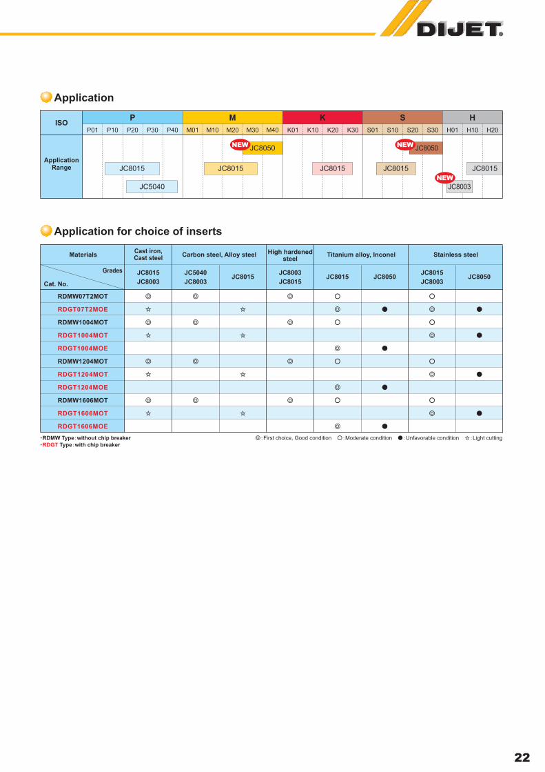
RDMW Type without chip breaker
RDGT Type with chip breaker
First choice, Good condition Moderate condition Unfavorable condition Light cutting
JC8015
22
Application
Application for choice of inserts
Materials
JC8015 JC5040JC8015
JC8003JC8015 JC8050
JC8015
JC8003 JC8003 JC8015 JC8003JC8050
Cat. No.
Grades
RDMW07T2MOT
RDGT07T2MOE
RDMW1004MOT
RDGT1004MOT
RDGT1004MOE
RDMW1204MOT
RDGT1204MOT
RDGT1204MOE
RDMW1606MOT
RDGT1606MOT
RDGT1606MOE
Cast iron,Cast steel
Carbon steel, Alloy steel High hardenedsteel
Titanium alloy, Inconel Stainless steel
K
JC8015 JC8015JC8015 JC8015
JC5040
JC8050 JC8050NEW NEW
P M S HISO
ApplicationRange
P01 P10 P20 P30 P40 M01 M10 M20 M30 S01 S10 S20 H01 H10 H20S30K01 K10 K20 K30M40
JC8003
NEW

DIJET INDUSTRIAL CO., LTD.
2-1-18, Kami-Higashi, Hirano-ku, Osaka 547-0002, JapanPhone: +81-6-6794-0167 Fax: +81-6-6793-3930
DIJET INDUSTRIAL CO., LTD.
(Europe)
DIJET EUROPEAN
TECHNICAL SERVICE
(Italy)
DIJET INDUSTRIAL CO., LTD.
Bangkok
Representative Office
DIJET INDUSTRIAL CO., LTD.
Shanghai
Representative Office
DIJET Incorporated
(U.S.A.)
Unit 2 Mundells Court, Welwyn Garden City,
Herts AL7 1EN, England
Phone. +44(0)1707-325444
Fax. +44(0)1707-330197
Via Sega 2618/B35010 San Giorgio in Bosco (PD) ItalyPhone. +39 049 599-4392Fax. +39 049 599-4935
699 Srinakarindr Road, Modernform Tower 15 th Floor, Kweang SuanluangKhet Suanluang, Bangkok 10250, ThailandPhone. +66(0)2-722-8258, 8259Fax. +66(0)2-722-8260
Room No.1007 Tomson Commercial Building.,
710 Dongfang Rd., Shanghai 200122
Phone. +86-21-5058-1698
Fax. +86-21-5058-1699
45807 Helm Street, Plymouth, MI 48170 U.S.A.
Phone. +1-734-454-9100
Fax. +1-734-454-9395
Overseas division:
printed 11/2006
WARNING:
Grinding produces hazardous dust.
To avoid adverse health, use adequate ventilation and
read Material Safety Data Sheet first.
Cutting tools may fragment in use.
Wear eye protection in the vicinity of their operation.
FAX 06-6793-1230
Japanese Web Site
Web Site:
m
Specification may be changed without notice.
Your local stockist is:


