
Pumps & MotorsSeries HD2 Axial Piston
Catalogue HY16-8002/UKJune 2001
Maximumimage area
2Hydraulics
Parker Hannifin plcIntegrated Systems DivisionWarwick, UK
Catalogue Number HY16-8002/UK
Hydraulic Axial Piston Pumps/MotorsIndexHD2 Series
Contents Page Number
Note: In line with our policy of continuing productimprovement, specifications in this catalogue are subject tochange without notice. There is always a possibility of errors.
Introduction 3
Operation 3
Basic Data 4
Fluids 5
Filtration 5
Noise 5
Mounting and Drive 5
Boost Pumps 6
Power Take Off Shafts 6Auxiliary Pumps 6Pump Mounted Circuit Valves
Purge Valve 7Pump Replenishing or Motor Purge Valve 8High Pressure Relief Valve 9
Control OptionsFixed Capacity 10Variable Capacity with Manual Control 10Pressure Compensated 10Overcentre Remote Control 11Overcentre Remote Control plus Pressure Override 11Overcentre Remote Control plus Horsepower Override 11Overcentre Remote Control with both Horsepower and Pressure Override 11Overcentre Remote Control with remote Electrical Control 12Overcentre Remote Control with Electro-Hydraulic Control 12Variable Capacity with Electro-Hydraulic Control 13Temperature Control for Fan Drives 13Constant Power Motor 13Constant Speed Control 14Load Sensing Control 14
Basic DimensionsManual Servo Unit, HD2-900 to HD2-4000 15/16HD2-6600 17Control Dimensions 18
Pump Performance Curves 19
Motor Performance Curves 20Order Codes 21Section View 22Application Examples 23

3 Parker Hannifin plcIntegrated Systems DivisionWarwick, UKHydraulics
Catalogue Number HY16-8002/UK
Hydraulic Axial Piston Pumps/MotorsIntroduction/ OperationHD2 Series
IntroductionThe HD2 range of fixed and variable displacement axialpiston units are designed for heavy duty, closed circuitapplications where high performance and reliability arerequired. The units are available with a wide range of controloptions and circuit valves offering greater flexibility to systemdesigners in cost effective packages.
The body materials are steel and cast iron enabling units tobe used underground when fitted with Parker’s cast ironbodied auxiliary pumps.
Closed circuit HD2 units are bi-rotational but boost orauxiliary pumps are sometimes suitable for one directiononly.
The HD2 range is designed with a B10 bearing life (less than10% failures) of 10,000 hours at continuously rated speedand pressure at maximum capacity on 21 centistokesmineral oil.
Operation of HD2 UnitsThe axial piston design is simple in concept allowing acompact, fixed or variable capacity unit to be producedcapable of being operated as a pump or motor in eitherdirection of rotation. Output flow of the variable capacity unitsis controlled by tilting the swashplate.
PumpsMultiple pistons are positioned axially in a rotor, which isconnected to the prime mover via a drive shaft. Each pistoncarries a “slipper” running against the inclined swashplate,both rotor face and slippers are pressure balanced andlubricated to minimise power losses.
The HD2 “floating” rotor face allows a rigid shaft with twohigh capacity bearings to be used and ensures a uniformrunning clearance, which reduces contamination sensitivityto a minimum.
As the rotor revolves, the cylinders follow the path of the inletkidney port, the angle of the swashplate causes the pistonsin the cylinder bores to move away from the kidney port thusdrawing fluid into the cylinder. Further rotation past “top deadcentre” brings the cylinder on to the path of the outlet portand causes the pistons to move downwards expelling thefluid through the outlet port.
Careful design and manufacture ensures hydraulic balanc-ing of internal forces and excellent lubrication of all bearingsurfaces in the pumps and motors to give long trouble-freelife with high overall efficiency.
MotorsThe construction of motors is identical to pumps; the fixedand certain types of the variable capacity units can be usedas either pump or motor. As a motor, fluid enters the cylin-ders positioned over the high pressure kidney port, thepistons in these cylinders are forced away from the kidneyport and reaction between the slipper pad on the piston andthe inclined swashplate results in a rotary movement of therotor and, hence, the output shaft.
A particular feature of the HD2 range is the excellent lowspeed and static performance made possible by the floatingrotor face.
ControlsIn the case of the fixed angle swashplate the outlet flow isdetermined only by the pump size and rotational speed. Withthe variable capacity units the angle of the swashplate canbe altered and the output flow varied proportionally. If theswashplate is moved over centre the direction of the flow isreversed.
Control of the swashplate is through an integral servoarrangement using fluid at delivery pressure for controlpower and rapid response. With the basic variable pump ormotor a manually operated follow-up servo control (MS)positions the swashplate in response to linear movements ofthe servo control rod. In this way reaction loads are elimi-nated from the external mechanical connections and theforces required are minimised. With the various automaticcontrols, additional features are incorporated which adjustswashplate angle in accordance with pressure or othercontrol parameters. Further details of the control optionsavailable are given on pages 10 to 14.
Circuit ValvesIntegral valves are available for the following:-
Cross line high pressure relief.
Replenishing valve to supply boost or make up oil intoclosed circuit systems.
Purge valve (hot oil valve) to remove excess oil from closedcircuits so cooling and filtering the main oil flow.
Valves can be fitted to pumps or motors.
Drive Shaft
Piston and SlipperAssembly
BobbinAssembly
Cartridge ReliefValve
Follow up Rotor Plate
High PressureRelief Valve
ReplenishingValve
Purge Valve
Port Block
Main FlowPort
Boost and/orAuxiliary Pumps
OCR Control Rotor
Servo PistonPilot Piston
ExternallyAdjustableStroke Stop
Adjustableswashplate
4Hydraulics
Parker Hannifin plcIntegrated Systems DivisionWarwick, UK
Catalog Number HY16-8002/UK
Hydraulic Axial Piston Pumps/MotorsBasic DataHD2 Series
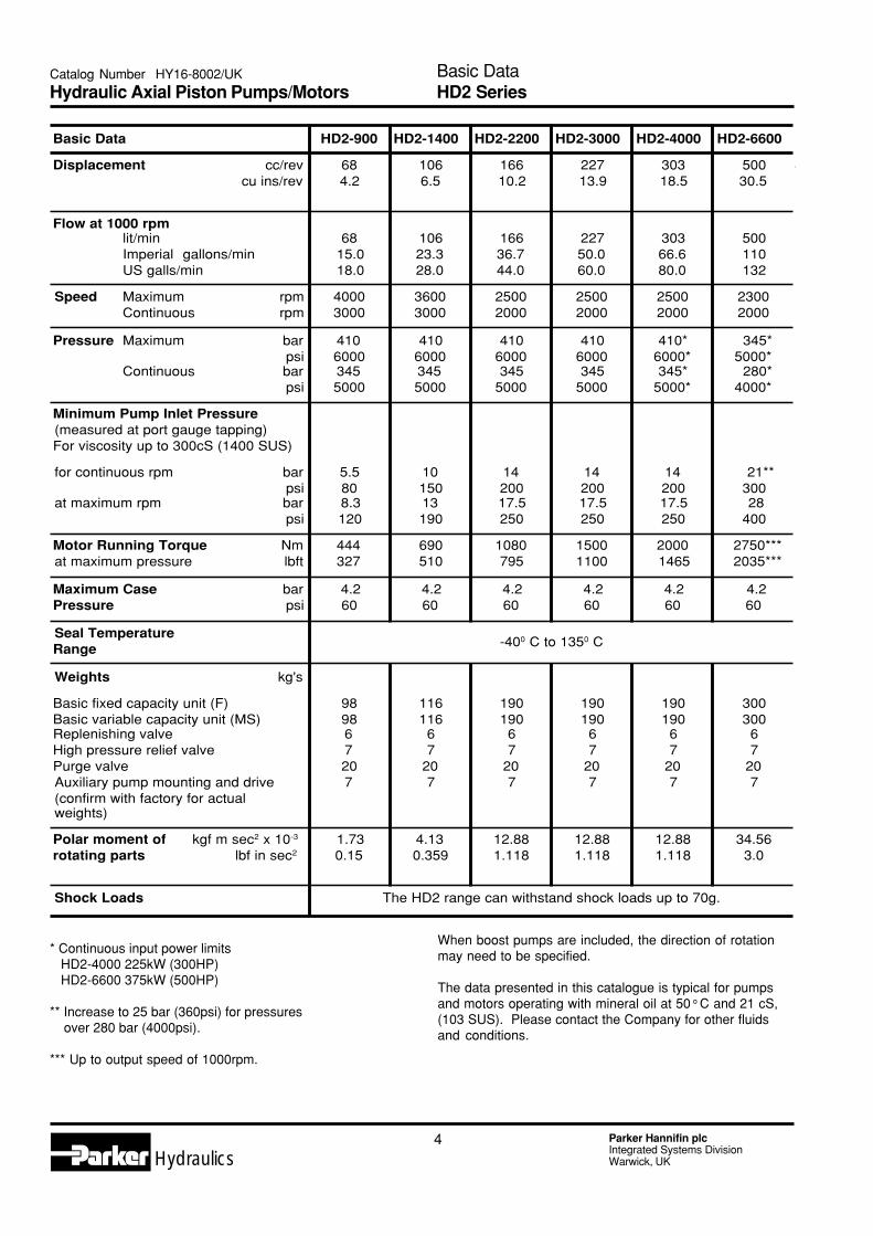
Basic Data HD2-900 HD2-1400 HD2-2200 HD2-3000 HD2-4000 HD2-6600
Displacement cc/revcu ins/rev
684.2
1066.5
16610.2
22713.9
30318.5
50030.5
Flow at 1000 rpm lit/min Imperial gallons/min US galls/min
6815.018.0
10623.328.0
16636.744.0
22750.060.0
30366.680.0
500110132
Speed Maximum Continuous
rpmrpm
40003000
36003000
25002000
25002000
25002000
23002000
Pressure Maximum
Continuous
barpsibarpsi
41060003455000
41060003455000
4106000345
5000
4106000345
5000
410*6000*345*
5000*
345*5000* 280*4000*
Minimum Pump Inlet Pressure(measured at port gauge tapping)For viscosity up to 300cS (1400 SUS)
for continuous rpm
at maximum rpm
barpsibarpsi
5.580
8.3120
1015013190
1420017.5250
1420017.5250
1420017.5250
21**300 28400
Motor Running Torqueat maximum pressure
Nmlbft
444327
690510
1080795
15001100
20001465
2750*** 2035***
Maximum CasePressure
barpsi
4.260
4.260
4.260
4.260
4.260
4.260
Seal TemperatureRange -400 C to 1350 C
Weights kg's
Basic fixed capacity unit (F)Basic variable capacity unit (MS)Replenishing valveHigh pressure relief valvePurge valveAuxiliary pump mounting and drive(confirm with factory for actualweights)
989867207
116116
67
207
190190
67
207
190190
67
207
190190
67
207
300300
67
207
Polar moment of kgf m sec2 x 10-3
rotating parts lbf in sec2
1.730.15
4.130.359
12.881.118
12.881.118
12.881.118
34.563.0
Shock Loads The HD2 range can withstand shock loads up to 70g.
* Continuous input power limits HD2-4000 225kW (300HP) HD2-6600 375kW (500HP)
** Increase to 25 bar (360psi) for pressures over 280 bar (4000psi).
*** Up to output speed of 1000rpm.
When boost pumps are included, the direction of rotationmay need to be specified.
The data presented in this catalogue is typical for pumpsand motors operating with mineral oil at 50 o C and 21 cS,(103 SUS). Please contact the Company for other fluidsand conditions.

5 Parker Hannifin plcIntegrated Systems DivisionWarwick, UKHydraulics
Catalog Number HY16-8002/UK
Hydraulic Axial Piston Pumps/MotorsFluids/ Filtration/ Noise/ Mounting and DriveHD2 Series
FluidsThe HD2 range is primarily designed to operate on hydraulicmineral oils with a viscosity of approximately 21 centistokesat normal operating temperatures.
Fully Approved FluidsHydraulic mineral oils to ISO 32 have passed the Compa-ny's Qualification Test Procedure to full specification and cantherefore be confidently recommended to ensure longtrouble free running with the HD2 Series.
This test procedure was introduced some years ago toprovide a guarantee of satisfactory operation, and is nowwidely recognised by both industry and oil companies asproviding a reference for oil performance with Axial PistonPumps. Based on the endurance of a standard pump withthe fluid concerned, the Company Procedure has been usedto evaluate a wide range of oils and provides a practicalbasis for complete fluid approval.
FiltrationThe HD2 units have special features to minimise the effectsof contamination, however, the importance of proper andadequate filtration cannot be over emphasised. All fluidpassing through the units should be filtered to 15 micron(0.0006ins/ 0.015mm) or better. The required cleanlinessstandard is 18/13 or better. Reference BS5540-ISO/DIS4406-CETOP RP 70H.
NoiseThe noise level of a complete hydraulic system is determinedby the pump or motor mounting and drive, the interconnect-ing pipework, the enclosure (if any around the equipment)and the basic noise level of the unit. As a general ruleincreasing speed and increasing pressure tend to increasethe noise level.
It is preferable to eliminate metal to metal contact in drivecouplings and to use short lengths of flexible hose betweenany solid piping and the units. On some applications it ispossible to mount the HD2 on flexible mountings and thiscan reduce the noise transmitted to the machine structure.
Noise reduction features have been incorporated into theHD2 range. As an example the basic HD2-900 has a noiselevel of 83dBA at 1500 rpm and 210 bar (3000 psi).
Mounting and DriveHD2 units can be mounted in any attitude but with very soliddrives it is essential that the shaft is aligned to normalengineering practices, ie 0.075mm (0.003in) T.I.R.
Torsionally flexible drives are preferred when the primemover is an internal combustion engine.
It is advisable to use anti-fretting paste on splined shafts.
The case drain should be arranged to keep the body full ofoil if it is mounted vertically and at least half full if it ishorizontal.
The mounting flange, drive shaft and main port flangesconform to SAE standards with the exception of the HD2-900ports which are tapped with a BSP thread.
Other Hydraulic OilsAny good quality mineral oil should be suitable for use withHD2 Pumps and Motors. For full duty operation –
Recommended minimum viscosity 15 cS (78 SUS).Recommended maximum viscosity 500 cS (2400 SUS).2000 cS (9500 SUS) allowable at cold start.
Other FluidsAlthough designed for use on mineral oils the standard HD2Pumps and Motors are also suitable for operation at speci-fied conditions on a wide range of alternative fluids.
Field and Laboratory operating experience has beenobtained on the following:
Phosphate Esters Naptha DistillateRolling Mill Oils KeroseneGas Oil Diesel Oil
Careful consideration must be given to operating conditions,circuit standard and pump seal standards when using thesefluids.
Water Based Fire Resistant FluidsISO HFB (water in oil emulsions 60/40) and ISO HFC (waterglycol) can be used with HD2 pumps up to a maximumspeed of 1500 rpm, maximum pressure of 200 bar andmaximum temperature of 50 o C.
Higher pressures and speeds may be achieved with certainfluids on intermittent duties.
The shafts will accept side loading, the amount dependingon the speed, pressure and swashplate angle. Maximumside loads for a pump running on full displacement onmineral oil at 1500rpm, 210 bar (3000psi) for a B10bearing life of 10,000 hours are:
HD2-900 360kgHD2-1400 544kgHD2-2200 770kgHD2-3000 590kgHD2-4000 360kgHD2-6600 1600kg
Please consult the Company if you intend to operate a unitwith greater loads than these, or with any end load.

6Hydraulics
Parker Hannifin plcIntegrated Systems DivisionWarwick, UK
Catalog Number HY16-8002/UK
Hydraulic Axial Piston Pumps/Motors
Boost PumpsThe inlet side of the HD2 pumps must be pressurised toreduce noise, prevent cavitation, give a cooling flow, andallow a good standard of filtration, all of which help toachieve a long trouble free life.
A wide range of boost pumps are available for mounting onthe HD2 pumps but the majority of applications can be metby either a small make up pump to replace leakage from aclosed circuit system or a full flow boost pump with acapacity of 10 to 15% above the axial piston pump for opencircuit systems in which all the return flow goes directly totank.
Typical make up boost pumps for use at the continuous ratedconditions with 21 centistokes mineral oils are as follows:
The above pumps have the following features:
Bi-rotationalSAE Splined ShaftEqual SAE Split Flange Ports Both Sides(flanges not supplied)Suitable for both Mineral Oils and 60/40 Water Oil EmulsionsISO HFB
The make up boost pump capacity for any particular systemmust be determined by the total system leakage and thepump drive speed.
Please contact our Technical Department or our overseasdistributors for further advice.
Power Take Off ShaftsThe through shaft design of HD2 units enables them to bemounted in tandem together with single or multiple gearpumps for boost and auxiliary duties. See separate datasheets for rear mounting flange and gear pump details.
On many systems this can eliminate the need for bulky andexpensive splitter gearboxes or separate drives givingsignificant overall cost savings N.B. The power input to thecomplete assembly should not exceed the maximum statedfor the first HD2 unit.
HD2-900 to 4000Standard PTOShaft capable of transmitting a continuous torque of 200 Nmequivalent to 62kW (84 hp) at 3000 rpm (31 kW (42 hp) at1500 rpm).
High Power PTOAvailable as an optional extra with a torque rating of 740 Nmequivalent to 229kW (307 hp) at 3000 rpm (114 kW (153 hp)at 1500 rpm).
The PTO shafts are not sealed and have a SAE 1.25 inchinvolute male spline with 14 teeth.
HD2-6600Standard PTOShaft capable of transmitting a continuous torque of 740 Nmequivalent to 153kW (206 hp) at 2000 rpm.
The PTO shaft is not sealed and has an SAE 1.25 inchinvolute male spline with 14 teeth.
High Power PTOShaft available as an optional extra with a torque rating of2750 Nm equivalent to 570 kW at 2000 rpm. This facilityallows the mounting of any HD2 unit, including another 6600in tandem to give a total capacity of 1000 cc/rev.
The PTO shaft is not sealed and has an SAE 2 inch involutemale spline with 15 teeth.Use SAE “E” or "F" auxiliary Pump Mounting only with thisPTO shaft.
Auxiliary Pump Mountings (see seperate data sheet)Without pump mounted purge valve
With pump mounted purge valveSAE 'B' (HD2-900) or SAE 'C' (HD2-1400 to 6600) 4 boltmounting auxiliary pumps must be used. SAE '6 bolt'mounting flanges can be fitted provided that only four boltsare used.
Boost Pumps/ P.T.O. Shafts/ Auxiliary PumpsHD2 Series
tsooB.niMyticapaC
)ver/cc(
tsooBdradnatSpmuP
)htdiWraeG(
noitarepOpooLdesolCroF
009-2DH 2.72 )"1(13P
0041-2DH 2.72 )"1(13P
0022-2DH 2.24 )"5.1(13P
0003-2DH 2.24 )"5.1(13P
0004-2DH 2.24 )"5.1(13P
0066-2DH 7.65 )"2(13P
pmuPeziS
OTPdradnatShgiH
rewoPOTP
009-2DH tlob4&tlob2,'D'ro'C','B'EAStoN
elbaliavA
0041-2DH tlob4&tlob2,'D'ro'C','B'EAStoN
elbaliavA
0022-2DH tlob4&tlob2,'D'ro'C','B'EAS 'E'EAS
0003-2DH tlob4&tlob2,'D'ro'C','B'EAS 'E'EAS
0004-2DH tlob4&tlob2,'D'ro'C','B'EAS 'E'EAS
0066-2DH tlob4&tlob2,'D'ro'C','B'EAS'E'EAS
'F'ro
7 Parker Hannifin plcIntegrated Systems DivisionWarwick, UKHydraulics
Catalog Number HY16-8002/UK
Hydraulic Axial Piston Pumps/MotorsCircuit ValvesHD2 Series
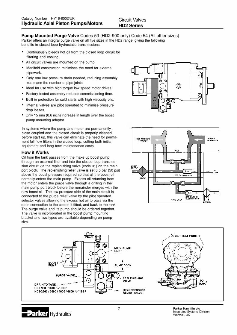
Pump Mounted Purge Valve Codes 53 (HD2-900 only) Code 54 (All other sizes)Parker offers an integral purge valve on all five sizes in the HD2 range, giving the followingbenefits in closed loop hydrostatic transmissions.
How it WorksOil from the tank passes from the make up boost pumpthrough an external filter and into the closed loop transmis-sion circuit via the replenishing valve (code 31) on the mainport block. The replenishing relief valve is set 3.5 bar (50 psi)above the boost pressure required so that all the boost oilnormally enters the main pump. Excess oil returning fromthe motor enters the purge valve through a drilling in themain pump port block before the remainder merges with thenew boost oil. The low pressure side of the main circuit isconnected to the purge relief valve by the pilot operatedselector valves allowing the excess hot oil to pass via thedrain connection to the cooler, if fitted, and back to the tank.The purge valve and its pump should be ordered together.The valve is incorporated in the boost pump mountingbracket and two types are available depending on pumpsize.
• Continuously bleeds hot oil from the closed loop circuit forfiltering and cooling.
• All circuit valves are mounted on the pump.
• Manifold construction minimises the need for external pipework.
• Only one low pressure drain needed, reducing assembly costs and the number of pipe joints.
• Ideal for use with high torque low speed motor drives.
• Factory tested assembly reduces commissioning time.
• Built in protection for cold starts with high viscosity oils.
• Internal valves are pilot operated to minimise pressure drop losses.
• Only 15 mm (0.6 inch) increase in length over the boost pump mounting adaptor.
In systems where the pump and motor are permanentlyclose coupled and the closed circuit is properly cleanedbefore start up, this valve can eliminate the need for perma-nent full flow filters in the closed loop, cutting both initialequipment and long term maintenance costs.

8Hydraulics
Parker Hannifin plcIntegrated Systems DivisionWarwick, UK
Pump Replenishing or Motor Purge Valve Code 31An adjustable low pressure relief valve for pump/motortransmission "make-up" and pilot operated low pressureselector valves are contained within a bolt-on-block. Two ofthese blocks can be used for purged closed loop systems ,one on the pump with its relief valve set to 3.3 bar (50 psi)higher than the second one fitted to the motor.For higher make-up flows additional low pressure selectorsand an additional low pressure relief valve are needed.The opening pressure of the low pressure relief valve isadjustable up to 70 bar (1000 psi).
Pump Replenishing or Motor Valve Diagram
Valve performance with an oil viscosity of 21 cS. This valvecan be used with or without the high pressure relief valve.
Circuit ValvesHD2 Series
Catalog Number HY16-8002/UK
Hydraulic Axial Piston Pumps/Motors

9 Parker Hannifin plcIntegrated Systems DivisionWarwick, UKHydraulics
Catalog Number HY16-8002/UK
Hydraulic Axial Piston Pumps/MotorsCircuit ValvesHD2 Series
High Pressure Relief Valve Code 35A high pressure, pilot operated, crossline relief valve forintermittent circuit protection is also available as a bolt-onfeature. This valve is adjustable up to 410 bar (6000 lbf/in˝)and has a facility to provide low pressure by-pass by ventingpilot pressure to tank.
Dual pressure settings are also possible by adding anexternal pilot valve to the vent connection. The pilot line andventing valves should be capable of passing a flow of 4.5 l/min (1 gpm).
One turn of the relief valve adjusting screw is equivalent toapproximately 70 bar (1000 psi).
When despatched the valve is set to 70 bar (1000 psi) unlessa specific setting is ordered.
This valve can be used with or without the replenishingvalve.
A HD2 Series PumpB Bolt-on Make-up and Axiliary PumpsC Bolt-on Replenishing Valve
D Bolt-on High Pressure Relief ValveE Purge ValveF Motor
N.B. If pumps run at high speed and zero displacement for prolonged periods werecommend that a low pressure cooling flow is passed through the body to prevent localoverheating.
Valve performance with an oil viscosity of 21 cS :-
Typical Circuit Diagram for Make-up Boost and Auxiliary Hydraulic Pumps

10Hydraulics
Parker Hannifin plcIntegrated Systems DivisionWarwick, UK
Catalog Number HY16-8002/UK
Hydraulic Axial Piston Pumps/Motors
Control OptionsThe HD2 swashplate is controlled by a servo piston which is powered by high pressure oil for rapid response. The oil passesfrom the main ports through a high pressure selector valve and internal drillings to the piston. Movement of the piston iscontrolled by the various alternatives shown below.
Fixed CapacityF (Code 1A)A fixed swashplate unit producing an output flow which is afunction of swept volume and rotational speed.
Screw AdjustableSA (Code 1)As fixed but with the capacity externally adjustable.
Variable CapacityWith Manual ControlMS (Code 2)Fully overcentre swashplate control for reversible flow.
Smooth infinitely variable output with continuous powertransmission.
Force required to operated MS control 67N (15 lbf). Re-sponse time is normally less than 0.2 seconds.
MSNS (Code 3)Control is similar to the MS with the addition of a positivespring centering device which gives an accurate zero flowposition especially useful for transmissions.
The force required to operate this control is 67N (15 lbf) atzero capacity rising to 98N (22 lbf) at maximum capacity.
MAMS (Code 4)Control is similar to the MS with the addition of a handwheelwith position indicator.
Pressure CompensatedCPSV (Code 6)Variable pump with stroke control to provide a constantpressure at the pump outlet. Maximum and minimum strokestops are provided. Vent allows complete off-load to zeroswash.
CPR (Code 6A)Overcentre option for rendering winches.Minimises power wastage, reduces oil heating and improvessystem response.
CPSVP and CRRP (Codes 6D and 6E)Controlled by external pilot pressure for remote control. Theratio between the pump delivery pressure and the pilotpressure is 20:1.
Damped Servo ResponseIf required an orifice can be fitted in the servo feed drillingunder plug X threaded 1/8 inch BSP.
An orifice is fitted as standard with the MSNS control.
All types have an adjustable pressure range 20 bar to 410bar (300 psi to 6000 psi) set to 70 bar (1000 psi) on des-patch. 1 turn is equivalent to 140 bar (2000 psi).
The system high pressure relief valve must be set above the compensator and will normally remain closed.
Control OptionsHD2 Series

11 Parker Hannifin plcIntegrated Systems DivisionWarwick, UKHydraulics
Catalog Number HY16-8002/UK
Hydraulic Axial Piston Pumps/MotorsControl OptionsHD2 Series
Overcentre Remote ControlOCR (Code 5)
Provides proportional control of swash angle by hydraulicpilot pressure signals derived from the system boost pres-sure operating a double acting control cylinder. Below thestart pressure the swashplate is spring centred to zero flow.Control orifices of 0.030 inches (0.75 mm) diameter are fittedas standard to the two control ports.
OCR/CHP (Code 5C)As basic OCR plus constant horsepower override controlwhich reduces pump displacement as pressure rises.
Controls are coded in horsepower per 1000 rpm.
The maximum and minimum settings for each size of pumpare as shown.
OCR/CHP/P (Code 5A)OCR with both constant horsepower and pressureoverride.
OCR/P (Code 5B)As basic OCR plus pressure override control whichreduces pump displacement towards zero to maintainconstant delivery pressure. The pressure setting is screwadjustable but it can also be varied remotely by a hydrau-lic pilot pressure signal derived from the system boostpressure. The ratio between pump delivery pressure andthe pilot pressure is 20:1. A preset maximum pressurestop can be incorporated.
OCRB/P (Code 5E) and OCRB/CHP/P (Code5D)OCR controls with the signal to CHP and P from the outerend of the OCR cylinder blanked off internally, this allowsthese controls to be used for crane and winch drives whenpaying out under load.
All OCR controls can be operatedremotely by proprietary joystickcontrollers with a suitable pressurerange.
tinU 009-2DH 0041-2DH0022-2DH
0066/0004/0003
tratS-/+erusserp
rab7.2isp93
rab4.3isp94
rab4.3isp94
yticapacxaMerusserp
rab6.9isp041
rab0.21isp571
rab8.41isp512
tolipkaePerusserp
rab53isp005
rab53isp005
rab53isp005
rednilyCx2tnemecalpsid
cc5.6 cc8.51 cc5.02
2DH 009 0041 0022 0003 0004 0066
rewoPniM Wkmpr0001rep ph
54.701
2.1151
6.8152
8.9204
3.7305
1.1628
rewop.xaM Wkmpr0001rep ph
3.7305
9.5557
28011
9.111051
1.941002
1.642033

12Hydraulics
Parker Hannifin plcIntegrated Systems DivisionWarwick, UK
Catalog Number HY16-8002/UK
Hydraulic Axial Piston Pumps/MotorsControl OptionsHD2 Series
OCR/E (Code N5, M5, L5 and T5)OCR with remote electrical control by low cost singlestage proportional pressure regulating valves which arepowered by boost pressure.This control mounts directly onto the side of the OCR andcan be used with /CHP/P and CHP/P options.A joystick or universal driver card is available as anoptional extra.
OCR/EH (Codes 5F, 5G, 5H and 5J)Combines the advantages of the OCR control with remoteelectrical operation by a high response proportional orservo valve.The output from the servo valve drives the OCR pistonwhich operates at low pressure. The servo valve cantherefore be powered by boost pressure eliminating theneed for a separate servo supply pump, filter and reliefvalve which are needed with the EH control.
The spring return to neutral of the OCR also allows lowcost controllers to be used. These controllers incorporate amechanical stroke position feedback signal which virtuallyeliminates hysteresis between the command signal and flowrate. For further details contact the Company.
Typical performance :-
N.B. Standard orifices are required for /CHP and /P options.
Command signal ± 2.7 volts DC 50 mA.Oil viscosity 21 cS (103 SUS).Supply 20 bar (300 psi).
HD2-900 HD2-1400 HD2-2200 to 6600
Response standard orifice 0 - max (secs) 1.4 1.6 2.2
Response standard orifice max - 0 (secs) 0.6 1.3 1.8
Response orifice 1.27mm (0.050") 0 - max (secs) 0.3 0.4 0.8
Response orifice 1.27mm (0.050") max - 0 (secs) 0.3 0.4 0.5Minimum control input pressure bar
psi12.6185
15220
17.8260
)SUS301(Sc12ytisocsivlionahtiwecnamrofreplacipyT 009-2DH 0041-2DH 0022-2DH0066/0004/0003
)sces(xam-0ecifirodradnatsesnopseR 4.1 6.1 2.2
)sces(0-xamecifirodradnatsesnopseR 6.0 3.1 8.1
erusserptupnilortnocmuminiM rabisp
6.01551
31091
61032

13 Parker Hannifin plcIntegrated Systems DivisionWarwick, UKHydraulics
Control OptionsHD2 Series
Catalog Number HY16-8002/UK
Hydraulic Axial Piston Pumps/Motors
Variable Capacity with Electro-HydraulicControl EH (Code 8)A variable capacity unit with facilities to move theswashplate using an electrical signal. A mounting base isprovided for various servo and high response proportionalvalves.
In its basic form control is achieved through a simplepotentiometer connected by wires to the pump. Electricalpower can be from a suitable DC supply. Full closed loopcontrol can be achieved through electronic modules and asuitable feedback transducer.
An independent oil supply between 28 bar (400 psi) and140 bar (2000 psi) is required to power the servo valve. Theflow depends upon the response time required. This oilsupply should be filtered to 10 micron or better and isusually supplied by a small auxiliary pump mounteddirectly onto the HD2 pump or its boost pump. For furtherdetails of the options available contact the Company
Temperature Control for Fan Drives TC(Code 6C)Pressure control sensing cooling water temperature. Hotwater increases signal pressure to provide more flow toraise motor and fan speed. Cooling reduces signalpressure to reduce flow and decrease fan speed inproportion irrespective of pump speed.
The Parker temperature sensor gives a low pressurehydraulic pilot signal to the pressure control which is alsosuitable for multiple sensors with highest error signalpriority.
Constant Power Motor CPM (Code 6B)Constant pressure control gives constant power output byvarying motor capacity between maximum and down to25% of maximum.

14Hydraulics
Parker Hannifin plcIntegrated Systems DivisionWarwick, UK
Control OptionsHD2 Series
Catalog Number HY16-8002/UK
Hydraulic Axial Piston Pumps/Motors
Contant Speed Control CD (Code 12)Constant output speed from the motor regardless of primemover speed variations. Typical applications: alternatorand compressor drives.
Principle of CD ControlThe flow from the motor mounted metering pump is used tomeasure speed by means of an orifice which may be fixedor variable. At a control pressure drop of 2.7 bar (40 psi)the pump capacity is increased or decreased to maintain aconstant motor speed typically within steady state accuracyof ±0.5%. This control cannot be used overcentre.
Load Sensing Control LS (Code 14)A pressure compensated pump with the delivery pressuredetermined by an adjustable bias spring setting “no load”pressure plus the load pressure sensed from an externalpilot line. The bias spring setting, typically 14 bar (200 psi),and the maximum pump delivery pressure, 14 bar (200 psi)to 345 bar (5000 psi), are independently adjustable.
Principle of Load Sensing Control
Flow control is achieved by placing a flow control orifice inthe pump output. The pressure drop across this orifice is thepressure that governs the pumps output flow. When thepressure drop across the orifice increases the pump willattempt to compensate by decreasing the output flow.Conversely the pump will attempt to increase flow when thepressure across the orifice decreases. The pump willalways try to maintain a constant pressure drop across theflow control orifice. The flow will therefore remain the sameregardless of the magnitude of the pressure in the system.
The flow will also remain relatively constant regardless ofthe drive speed of the pump within displacement andpower limitations of the system.

15 Parker Hannifin plcIntegrated Systems DivisionWarwick, UKHydraulics
Catalog Number HY16-8002/UK
Hydraulic Axial Piston Pumps/MotorsHD2-900/4000 Basic DimensionsHD2 Series

16Hydraulics
Parker Hannifin plcIntegrated Systems DivisionWarwick, UK
Catalog Number HY16-8002/UK
Hydraulic Axial Piston Pumps/MotorsBasic DimensionsHD2 Series
The use of SAE standard mountings and drive shafts enablesthe HD2 range to be readily fitted to proprietary pump drivesplitter gearboxes or to motor reduction gearboxes when hightorque low speed drives are required.
For the supply of the relevent port flanges use Code 70.
Symbol HD2-900 HD2-1400 HD2-2200/3000/4000
mm Inches mm Inches mm Inches
A 327 12.875 376.2 14.813 460.4 18.125
B 247.7 9.75 294.5 11.594 371.5 14.625
C 350.8 13.813 444.5 17.5 520.7 20.5
D 239.7 9.437 222.3 8.75 276.2 10.875
E 168.3 6.625 218.3 8.594 262.7 10.344
Dia. F 152.4 +0/-.05 6.000 +0/-.002 152.4 +.0/-.05 6.000 +0/-.002 165.1 +.0/-.05 6.500 +.0/-.002
G 25.4 1 27.0 1.063 31.7 1.25
H 12.7 0.25 12.7 .5 15.9 .625
J 98.4 3.875 114.3 4.5 150.8 5.938
K 31.8 1.25 38.1 1.5 46.0 1.813
L 47.6 1.875 57.2 2.25 58.7 2.313
M 200 7.875 203.2 8 261.9 10.313
N 266.7 10.5 269.9 10.625 355.6 14
R 79.4 3.125 104.8 4.125 119.1 4.688
S 155.6 6.125 174.6 6.875 223.8 8.813
T 41.3 1.625 71.4 2.813 65.1 2.563
Dia. U 8.64 +/-.13 .340 +/-.005 12.69 +.0/-.02.4997 +.0/-.0008 12.69 +.0/-.02
.4997 +.0/-
.0008
Dia. V 2.4 +.08 -.0 .094 +.003/-.0 4.9 +.08/-.0 .192 +.003/-.0 4.9 +.08/-.0 .192 +.003/-.0
W 20.6 0.813 23.8 .938 31.8 1.25
X 20.6 0.813 23.8 .938 31.8 1.25
Y 41.3 1.625 59.5 2.434 53.2 2.094
Z (P.C.D.) 228.6 9.000 228.6 9.000 317.5 12.500
Mounting flangeand drive SAE D
OptionSAE C 2 bolt SAE D SAE E
Pressure Ports2 x 1.25" BSP or 2 x 1.25" SAE62
0.5" UNC or M142" SAE620.75" UNC or M20
2" SAE620.75" UNC or M20

17 Parker Hannifin plcIntegrated Systems DivisionWarwick, UKHydraulics
Catalog Number HY16-8002/UK
Hydraulic Axial Piston Pumps/MotorsHD2-6600 Basic DimensionsHD2 Series

18Hydraulics
Parker Hannifin plcIntegrated Systems DivisionWarwick, UK
Catalog Number HY16-8002/UK
Hydraulic Axial Piston Pumps/MotorsControl DimensionsHD2 Series

19 Parker Hannifin plcIntegrated Systems DivisionWarwick, UKHydraulics
Pump PerformanceHD2 Series
Catalog Number HY16-8002/UK
Hydraulic Axial Piston Pumps/Motors

20Hydraulics
Parker Hannifin plcIntegrated Systems DivisionWarwick, UK
Motor PerformanceHD2 Series
Catalog Number HY16-8002/UK
Hydraulic Axial Piston Pumps/Motors

21 Parker Hannifin plcIntegrated Systems DivisionWarwick, UKHydraulics
Catalog Number HY16-8002/UK
Hydraulic Axial Piston Pumps/MotorsOrder CodesHD2 Series
Ordering Code Example: HD2/4000/5/20/31/35/51/P30 C 678 BE PO 15-7/ 80
HD2 / / / / / / / /
Size900
14002200300040006600
Shaft High PressureRelief Valve
AuxiliaryPump Type
Number
AuxiliaryPump Mounting
PortConnections
KeyStandardPTO
KeyHighPowerPTO
SplineStandardPTO
SplineHigh PowerPTO
Inlet andoutlet portflanges formain pump
20
20H
21
21H
35 70
ReplenishingValve
31
31A
31B
LP. PORT QHP. PORT PLP. PORT PHP. PORT Q
3PA European Std.
3.5PA European Std.
4PA European Std.
SAE "B" 2 and 4 Bolt
SAE "C" 2 and 4 Bolt
SAE "D" 2 and 4 Bolt
SAE "B" 4 Bolt with purge HD2-900 only
SAE "C" 4 Bolt with purge HD2 1400 to
PM60
SAE E / To suit HD2 - 2200/4000
SAE F / To suit HD2 - 6600
6600 only
PREFERRED STANDARDBSP PORTS + UNCTHREADSALTERNATIVE OPTIONS.
SA
MS
MSNS
MAMS
OCR
5+ /E
FIXED WEDGE
OCR/CHP/P
5A+ /E
OCR/P
5B+ /E
OCR/CHP
5C+ /E
OCRB/CHP/P
OCRB/P
OCR/EH
OCR/EH/CHP/P
OCR/EH/P
OCR/EH/CHP
For horsepower controls addinput power and speed
BSP+ METRIC THREADS
METRIC STRAIGHTO RING BOSSISO 6149+ METRIC THREADS
S.A.E. STRAIGHT O RINGBOSS + UNC THREADS
CPSV
EH
CD
LS
CPR CPM TC CPSVP CPRP
Ancillary items
Advise any special features if required
Temperature sensor for use with TC pump (35oC to 60oC)
Temperature sensor for use with TC pump (60oC to 100oC)
6
8
12
14
6A 6B 6C 6D 6E
75
76
5D
5E
5F
5G
5H
5J
5C
T5
5B
L5
1
2
3
4
5
N5
Control
41
42
43
50
51
52
53
54
55
56
57
5A
M5
1A 82
81
80
83

22Hydraulics
Parker Hannifin plcIntegrated Systems DivisionWarwick, UK
Catalog Number HY16-8002/UK
Hydraulic Axial Piston Pumps/MotorsSection ViewHD2 Series

23 Parker Hannifin plcIntegrated Systems DivisionWarwick, UKHydraulics
Catalog Number HY16-8002/UK
Hydraulic Axial Piston Pumps/MotorsApplication ExamplesHD2 Series

Parker Hannifin plcIntegrated Systems DivisionTachbrook Park Drive, Tachbrook ParkWarwick, CV34 6TU, ENGLANDTel. +44 (0) 1926 833700, Fax. +44 (0) 1926 889172www.parker.comEuropean product information centre: 00800 27 27 5374
Please contact our sales representative:


