Download - Rastegar UPW v2

© SEMATECH, Inc. SEMATECH, SEMATECH, Inc. and the SEMATECH logo are registered service marks of SEMATECH, Inc. All other service marks and trademarks are the property of their respective owners.
Understanding UPW-induced particle
defectivity in sub10 nm technology
nodes
Abbas Rastegar
Matt House, Martin Samyoa
SEMATECH
Albany- New York
December 2014

A. Rastegar
Outline
2
• Particle defectivity in advanced technology nodes
• Particles in UPW systems
• Particle interactions and behavior
• Correlation between particles in solutions and on the surface
• Challenges of measuring low concentration of particles in UPW
• Particle removal in sub 10 nm HP technology nodes

A. Rastegar
Yield challenges in 14 nm HP node
3
• Yield improvement for 14 nm HP node is much slower than that of 22 nm HP node
• Particle defectivity is one of the key challenges of yield at 14 nm HP node
Intel.com ( 2014 November)

A. Rastegar
More particles in 3D gate structures
22 nm FinFET-Intel
• Replacement gate structures require more CMP steps ( 4X) more particles
• Fins aspect ratio increases particle traps, more difficult to inspect
• Fins become structurally weaker difficult to clean
Images: Courtesy of Mark Bohr- Intel
9 December 2014 4
P. Feeney, SST, Nov. 2010

A. Rastegar
CMP for the gate-last FinFET processes
5
• Multiple CMP processes are required during a replacement gate process
• Particles generated during CMP have many different compositions
Integration sketch: Tat Ngai
Last CMP step in (Gate last or Replacement Gate) integration

A. Rastegar
New Materials in Semiconductors
• Many new materials are introduced in the semiconductor manufacturing which result in particles with many different compositions
• Particle interaction with surface depends on their compositions
Source :David Gilmer-SEMATECH
6

A. Rastegar
Particles in UPW systems
7
Pretreatment System
Reverse Osmosis
Vacuum Degasifier
Ion Exchanger
UPW Tank
I.E or MB polisher
Ultra- Filtration
Heat Exchanger
• UPW system for semiconductor applications are using multiple modules with different functionalities
• Each module and component contribute to particle defectivity • Particles can be generated from components in contact with UPW
– Tubing, Pumps, Valves, Regulators, Flow meters, Heater, Sensors, Tanks, Fittings, UV, Filters, Ion exchange resins
• Focus of today’s talk is on understanding nanoparticle behavior in UPW system
UV (185 nm)

A. Rastegar
Particle behavior and interactions in UPW
8
Particle behavior Particle interactions
• Particle behavior in the UPW can be explained by particle interactions with surface, flow and light and their subsequent interactions

A. Rastegar
Particle generation in UPW
9
• How particles are generated in UPW? – Transport from outside by incoming water – Release from a surface
• Vibration • Heat • Shear stress by flow variation • Contact
– Generated from a surface • Contact • Cavitation • Mechanical stress (cracks)
– Form in UPW • Agglomeration • Precipitation • Flocculation
Source: internet

A. Rastegar
Particle transport in UPW
10
Pipe diameter ( 4 mm)
p
cc
DD vd
CC
FF 3
1
Drag force is effective
Brownian diffusion
• Particles in the boundary layer will not be affected by bulk flow and eventually will reach the surface
• Even in very fast flows hydrodynamic boundary layers are of orders of 10’s of microns
Parabolic flow in a tube

A. Rastegar
UPW tubing: Particle retention and release
11
• Nanoparticles in solution eventually will pass the boundary layer and come into contact with surface
• When particles are in contact with surface they cannot be removed by flow
Boundary layer
Bulk flow(advection)
Time
Surface (wafer, pipe, filter,…)
Controlled release of particles

A. Rastegar
Particle retention and release in UPW tubing
12
• Particles in UPW are continuously deposited on the surface of tubing and other components.
• High density of particles can be released from surfaces
• No tubing stay clean for long time!
½ inch PFA tube Length 20 mm
Random burst of particles detected @ 25 nm channel during night time (no cleanroom activity)

A. Rastegar
Open
0.5 L/min
20 mL/min
Simulations: Huseyin Kurtuldu
Particle trajectory
500 mL/min
20 mL/min
Open (480 mL/min)
10 m pore -100 m space T fitting Single membrane filter
• Particles distribution in the flow is not uniform
• In slow flows, particle diffusion dominates and particles reach to the surface by Brownian motion
Particle-flow interactions
A. Rastegar
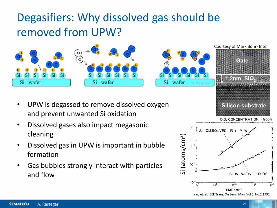
Degasifiers: Why dissolved gas should be removed from UPW?
14
• UPW is degassed to remove dissolved oxygen and prevent unwanted Si oxidation
• Dissolved gases also impact megasonic cleaning
• Dissolved gas in UPW is important in bubble formation
• Gas bubbles strongly interact with particles and flow
Yagi et. al. IEEE Trans. On Semi, Man. Vol 5, No.2.1992
Si (
ato
ms/
cm2)
Courtesy of Mark Bohr- Intel

A. Rastegar
Controlling dissolved gas in UPW for megasonic cleaning
In-situ dissolved gas chromatography was used to measure dissolved gas concentration in UPW

A. Rastegar
Megasonic damage by dissolved oxygen in UPW
• Dissolved gas in UPW is extracted in cavitation bubble by acoustic waves
• The higher the gas content the higher is cavitation which means more damage
• Sonication of UPW with dissolved oxygen creates OH radicals that are very active and damage the surface
Damage on EUV mask blanks
OH radical formation in UPW by megasonic

A. Rastegar
Bubble-Particle interactions Dissolved gas in UPW
• Bubbles are formed when the concentration of dissolved gas in UPW is more than its saturated solubility limit
• Saturated solubility depends on gas pressure, type and temperature
Effects of Temperature on Quantity of Dissolved CO2, O2, N2, and He in UPW (at partial pressures of 1 atm).
Fig. 3 Effects of Pressure (Partial Pressure) on Solubility of O2 in 1 mL Water (at 25 °C)
Bubble
Particle
Bubble Bubble
Bubble UPW
Air interface
Wal
l
• Bubble interactions
– Bubble-particle
– Bubble-bubble
– Bubble-surface/interface

A. Rastegar
Heat exchangers-UPW temperature and particles
18
Hot (80C)
Cold (17C)
Ad
din
g C
O2
PMS –CLS 1000
• Increasing temperature results in bubble
• Nonvolatile residues (NVR) and particles are attracted to the water-bubble interface
• Bubbles attach to the surface and leave residues
Particles in UPW
Uwe Dietze- Suss Microtec- nanoparticle workshop 2013
Particles on surface
Part
icle
s p
er
mL

A. Rastegar
UPW heaters and particle generation
19
• The surface of quartz heaters reach to the temperature of about ~ 350C
• Silica will be dissolved from heater wall into the UPW by heat and appear as nonvolatile residue
• High shear stress by flow on very hot surface of quartz tubing release particles from the surface
• Temperature change also affect particle dynamics – Both bulk and shear viscosity reduces – Particles move from hot surface toward cold
(Thermophoretic force )
Temperature (C )
Solu
bili
ty o
f Si
O2 (
%)
Handbook of cleaning for semiconductor Manufacturing - Reinhardt & Reidy
20C 80C
Holms, Parker, Povey, J.O. Physics, Conf. Proc. 2010

A. Rastegar
Nanoparticles formed from dissolved silica in UPW
• Nonvolatile residues from nanodroplets are very flat with thickness about 4 nm
• These nanoparticles are coming form dissolved silica in UPW

A. Rastegar
UV radiation and particle formation in UPW
21
172 nm@ 7.2 ev
Discharge O3 generator 3 nm gas filter No filter for ozonated UPW
• UV light (l< 200 nm) is able to breakdown many organic molecules
• Fitting and tubing exposed to UV become brittle and form cracks and eventually under stress release particles
• UV will oxidize metallic ions and they will precipitate as particles
• UV generate ozone and ozone react with tubing and metallic surfaces and generate particles
• UV react with quartz surface and increase Si dissolution
)(
1240)(
nmeVE
hcE
l
l
185 nm 6.7 ev
Wibowo, Shadman, Blackford, Am. Fluid Technologies
185 nm
254nm

A. Rastegar
Particle-surface interactions in UPW in nano-scale
22
Hydrodynamic boundary layer
Bulk flow(advection) Order of micrometer and reduces by increasing flow velocity
Electrostatic double layer
Diffusion layer
Order of nanometer and reduces by increasing ionic strength
• A particle may deposit or repel from surface depending on zeta potential of surface and particle and pH of solution

A. Rastegar
Particle deposition in UPW– electrostatic interactions
23
During UPW rinse Al2O3, Fe2O3 particles will not be deposited on RuO2 surface ( Same sign of z potential) but will be deposited on the quartz surface ( different sign of z potential)
colloidal silica particles will be deposited on RuO2 surface but will Not be deposited on the quartz surface during UPW
• Depending on the pH of the solution, zeta potential of the surface and particles, some particles may or may not be deposited on a surface

A. Rastegar
Summary of particle interactions
24
vdWF
Particle DF
ELDFFlow
p
ScattI .
S
ScattI .
S
refIp
refI
S
absIp
absI
),(0 lI
Wafer
Particle
),(0
lI p
ScattI .
m
ScattI .
m
refIp
refI
m
absIp
absI
A. Rastegar
Particle
Media
Liquid cell Fl
ow
In solution On surface
Particle-light interaction

A. Rastegar
Particle detection and sizing in solutions and on a surface?
9 December 2014 25
Measure particles in solutions Transfer particles to the surface Measure particles on surface
p
ScattI .
S
ScattI .
S
refIp
refI
S
absIp
absI
),(0 lI
Wafer
Particle
),(0
lI p
ScattI .
m
ScattI .
m
refIp
refI
m
absIp
absI
A. Rastegar
Particle
Media
Liquid cell
Flo
w
• Incident light ( l,)
• Particle properties • Shape, size, composition
• Media properties ( UPW, Chemicals) • molecular scattering,
absorption
• Incident light ( l,)
• Particle properties • Shape, size, composition
• Surface properties (Roughness) • Scattering , reflection and
absorption
Intensity of the scattered light
Particle size
Particle detection in solutions Particle detection on surface

A. Rastegar
Particle size and composition
26
x1,000
x1,000,000
x10
K. Kondo et.al., JSAP(2013)
• Scattered light is proportional to
• (1/ wavelength4) shorter wavelengths lead to higher sensitivity
• (particle diameter)6 Sensitivity drastically reduces for small particles
• Type of calibration particles determine pixel size of LPC and inspection tools
Rayleigh approximation

A. Rastegar
Particle detection efficiency on a surface
27
• Optical properties of particles and surface determine particle detectability on a surface
• As the calibration particles are fixed on the surface, multiple inspections results in reliable measurement of the particle detection efficiency
• High detection efficiency ( 95% to 99%) at the tool sensitivity is achievable
• Due to high capture efficiency very low defect concentration on surface are detectable ( ~10 defects)
Inspection wavelength =266 nm, SiO2 particles, Inspection wavelength =485 nm on quartz surface

A. Rastegar
Particle detection efficiency in solutions
28
• Multiple detections of the same particles in solution is not feasible
• Detections of known particles with known concentration is used to measure detection efficiency
• Preparation of nanoparticles with known concentration is very challenging
• In practice, h is measured by diluting a known concentrated of known particles.
• This technique works for higher particle concentration.
K. Kondo , Bunseki, Vol.9 P499 (2012)
Ideal LPC
Real LPC
%100100.
ConKnown
ConMeasuredh
%3h
A. Rastegar
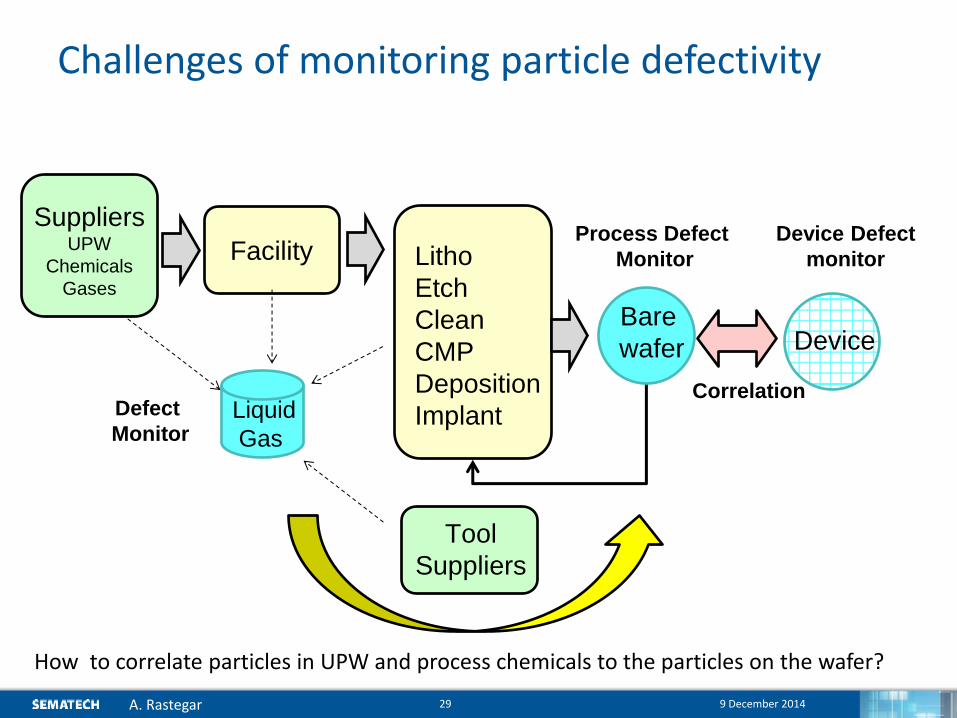
Challenges of monitoring particle defectivity
9 December 2014 29
Fab Device Defect
monitor Facility
Device
Suppliers UPW
Chemicals
Gases
Litho
Etch
Clean
CMP
Deposition
Implant
Tool
Suppliers
Process Defect
Monitor
Bare
wafer
Correlation Liquid
Gas
Defect
Monitor
How to correlate particles in UPW and process chemicals to the particles on the wafer?

A. Rastegar
Particles during rinse and dry processes
9 December 2014 30
Drying and evaporation
Particle dynamics in the flow Particle –surface interaction
Fluid dynamic
Fluid properties
Nozzle parameters
Surface energy Contact angle Surface roughness Surface composition Underlayers Surface charge
surfactant
• Many parameters contribute to particle adders on surface
• Standard processes ( rinse, dry, surface, particle type) should be developed to get reproducible number of particles on surface
Pro
cess
ch
em
ical
s
Wafer

A. Rastegar
Correlating of particles on surface and on UPW
31
• Particle release experiment
• LPC
• Surface Ru capped mask blank
• Standard rinse /dry
• Two different inspection tools was used
• Results
• Released particles have different size, shape and compositions (i.e. native particles)
• Only qualitative correlation can be seen with tool with higher sensitivity

A. Rastegar
Correlation of particles in UPW and on surface
32
( mostly Al2O3)
ITRS-WG experiment 90 nm SiO2 particles KLA -SP1 ( 90 nm sensitivity)
S. Libman – UPW conf. 2014 Native particles (mostly metal oxide) >40 nm ,Lasertec M7360 ( 30 nm PSL sensitivity)
• Real (native) particles have different sizes, shapes and composition
• Particle counts on surface and in solution are linearly correlated, however, the linear slope depends on particle and surface parameters as well as inspection tools

A. Rastegar
Detection efficiency in low particle concentrations
33
• All metering pumps adding particles to UPW
• Alternative technique should be used for measuring LPC detection efficiency in low particle concentration

A. Rastegar
Particle measurement in low concentrations
34
• In low particle concentrations , particle dynamics should be considered. ( particles do not behave like molecules, i.e. dilution)
• Other sources of noise in LPC ( electrical, optical, detection, Gama,..) become significant
Calibration particles size 3X of LPC sensitivity
particles size 30% > LPC sensitivity
%5h
%100h
Working range of this LPC Different Physics
M. Samayoa-SEMATECH

A. Rastegar
Measuring particle trends in UPW (low particle concentrations)
35 Experiments: Matt House
• Comparison of particle count of different LPCs for low particle concentration is challenging

A. Rastegar
Gaps in Particle Metrology-modified
9 December 2014 36
UPW
Chemicals
Slurries LPC
100 nm
50 LPC
20 nm 25
SPM (SEM,AFM)on surface
Inspection tool
50 nm
PIV -200 nm
22 30
108
107
106
105
104
103
102
10
0
2 5 10 20 30 50 100 200 300 500 1000
Size (nm)
Part
icle
count (
per
mL)
A. Rastegar SEMATECH
Aerosol metrology(DMA+CPC)
DLS
LIBS
in situ -OPC in situ -other
On surface
DMA: Differential Mobility Analyzer
CPC: Condensation Particle Counter
DLS: Dynamic Light Scattering
SPM: Scanning Probe Microscopy
LPC: Liquid Particle Counter
PIV : Particle Imaging Velocimetry
LlBS: Laser Induced Breakdown Spectroscopy
1
30

A. Rastegar
Current capabilities
Required capabilities
Data extracted from presentation by Don Grant et.al at UPW micro conference 2013
A. Rastegar
Particle filtration challenges
9 December 2014 37
12 nm SiO2 particles, face velocity 4 cm/ min, 0.2 monolayer coverage
• No detection tool exists for developing filters with high retention for low particle concentration (~10 particle/mL) at sub 10 nm sizes
• Existing infrastructures can study filter retentions in very high particle concentrations
Micron scale pores in a 10 nm class filter
10 m
10 nm - filter

A. Rastegar
Particles released from components in UPW
38
• During manufacturing of valves, pumps, filters, fittings, tubes surfaces of fluorinated polymers (PFA,, PTFE) com into contact with other materials ( Al2O3, Stainless steel)
• Nanoparticles generated during part manufacturing can not be removed and will be released in UPW

A. Rastegar
Sub 10 nm particles in UPW
9 December 2014 39
Particle Height
0
2
4
6
8
10
12
14
16
18
20
1 2 3 4 5 More
Height (nm)
Co
un
t
Random burst of very small particles (>2.5 nm) in UPW
Small organic particles are agglomerated
• There are many sub 10 nm particles in UPW that will end up on surface and can not be detected

A. Rastegar
New particle removal technology for sub 10 nm HP nodes
9 December 2014 40
Pattern : 65 nm SiO2 Particles: 50 nm PSL Process: Particle dep rinse dry
• Gigasonic cleaning is a new technology for particle removal for sub10 nm HP nodes that is under development in SEMATECH

A. Rastegar
Summary and Conclusions
41
• Advanced technology nodes are using surfaces with higher topography which are prone to particles
• Many components in UPW systems are contributing to particle defectivity – Degasification, heating and UV exposure impact particle
defectivity in UPW
• Interaction of particles with surface and flow determines particle deposition and release in UPW
• Correlation particles in UPW and on surface is challenging and depends on many parameters
• There are increasing evidence of sub 10 nm particles in UPW, but current particle metrology can not sufficiently detect these particles


