RIGOL User’s Guide
DG1000 Series Dual-Channel Function/Arbitrary
Waveform Generator
Jul. 2012
RIGOL Technologies, Inc.

RIGOL
© 2008 RIGOL Technologies, Inc. User’s Guide for DG1000
I
Guaranty and Declaration
Copyright ©2008 RIGOL Technologies, Inc. All Rights Reserved. Trademark Information RIGOL is registered trademark of RIGOL Technologies, Inc. Publication Number UGB06124-1210 Notices RIGOL products are protected by patent law in and outside of P.R. China. RIGOL Technologies, Inc. reserves the right to modify or change part of or all
the specifications and pricing policies at company’s sole decision. Information in this publication replaces all previously corresponding material. RIGOL shall not be liable for losses caused no matter by incidental or by
consequential in connection with the furnishing, use or performance of this manual as well as any information contained.
Any part of this document is forbidden to be copied or photocopied or rearranged without the express written approval of RIGOL.
Product Certification
RIGOL guarantees this product conforms to the national and industrial standards in China as well as the ISO9001:2008 standard and the ISO14001:2004 standard. Other international standard conformance certification is in progress. Contact Us If you have any problem or requirement when using our products, please contact RIGOL Technologies, Inc. or your local distributors, or visit: www.rigol.com.

RIGOL
© 2008 RIGOL Technologies, Inc. User’s Guide for DG1000
II
Safety Notices
Review the following safety precautions carefully before operating the instrument to avoid any personal injury or damage to the instrument or products connected to it. To avoid potential hazards, use the instrument in the manner specified in this user’s guide.
The instrument should be serviced only by qualified personnel.
Avoid Fire or Personal Injury.
Use Proper Power Line. Only the special power line of the products approved by the State should be used.
Ground the Instrument. This generator is grounded through the protective terra conductor of the power cord. To avoid electric shock, the grounding conductor must be connected to the earth ground. Make sure that the instrument is properly grounded before connecting the input or output terminals.
Observe All the Ratings of the Terminal. To avoid fire or shock, observe all the ratings and symbols that marked on the instrument. Read the user’s guide carefully before making connections to the instrument.
Do not Operate without Covers. Do not operate your generator without covers or panels.
Use Proper Fuse. Only use the fuse type and rating specified for this product.
Avoid Circuit or Wire exposed. Do not touch the exposed connections or components when the power is turn-on.
Do not operate with suspected failures. If you suspect there is damage with this product, have it inspected by qualified service personnel authorized by RIGOL before further operations.
Provide Proper Ventilation.
Do not Operate in Wet/Damp Conditions.
Do not Operate in an Explosive Atmosphere.
Keep the Product’s Surfaces Clean and Dry.
RIGOL
© 2008 RIGOL Technologies, Inc. User’s Guide for DG1000
III
Safety Terms and Symbols
Terms in This Guide. These terms may appear in this manual:
WARNING: Warning statements indicate the conditions or practices that could result in injury or loss of life.
CAUTION: Caution statements indicate the conditions or practices that could result in damage to this product or other property.
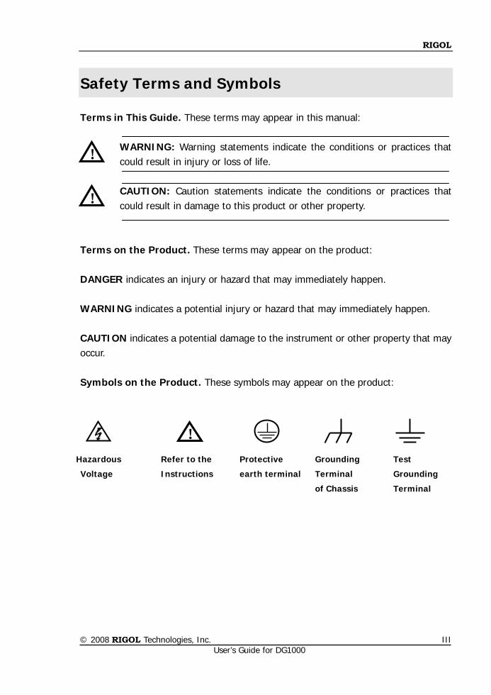
Terms on the Product. These terms may appear on the product: DANGER indicates an injury or hazard that may immediately happen. WARNING indicates a potential injury or hazard that may immediately happen. CAUTION indicates a potential damage to the instrument or other property that may occur. Symbols on the Product. These symbols may appear on the product:
! Hazardous
Voltage
Refer to the
Instructions
Protective
earth terminal
Test
Grounding
Terminal
Grounding
Terminal
of Chassis
!
!
RIGOL
© 2008 RIGOL Technologies, Inc. User’s Guide for DG1000
IV
Instrument at a Glance
RIGOL DG1000 series Dual-Channel Function/Arbitrary Waveform Generator adopts the DDS (Direct Digital Synthesis) technology, which can provide stable, high-precision, pure and low distortion sine signal. It can also provide 5MHz square waveform with fast rising and falling edges. In additional, frequency measurement function with high accuracy and wide frequency band is also provided. The combination of excellent system features, easiness in usage and versatile functions makes this generator a perfect solution for your job now and in the future. DG1000 series Dual-Channel Function/ Arbitrary Waveform Generator have clear and simple Front-Panel. The user-friendly panel layout and instructions, versatile interfaces, direct graph interface, built-in instructions and help system have greatly simplified the operation process, thus, users do not have to spend a great deal of time learning and familiarizing the operation of the generator before they can use it proficiently. The built-in AM, FM, PM and FSK modulating functions generate modulated waveform at ease, without the help of a separate modulating source. The USB I/O is the standard accessory. Main Features: DDS technology provides precise, stable and low distortion signal. 2-Channel Output. Support channel coupling, channel copy. 5 basic waveforms and 48 built-in arbitrary waveforms output. 100MSa/s sampling rate, enable to edit arbitrary waveform with 14-bit, 4k points. Abundant modulation function, various modulated waveform: AM, FM, PM and
FSK. Linear, logarithm Sweep and Burst mode. Abundant I/O interfaces: External Modulation Source, External 10 MHz Reference
Input, External trigger source, waveform output, synchronous signal output. Counter with high accuracy and wide frequency band can measure frequency,
period, duty cycle, positive pulse width and negative pulse width of the signal with the frequency from 100mHz to 200MHz (single channel).
Support USB flash storage device. You can store waveform parameters or the edited arbitrary waveform in USB flash storage device or read the waveform stored in the device as well as updating the system using the device.
RIGOL
© 2008 RIGOL Technologies, Inc. User’s Guide for DG1000
V
Standard interfaces: USB Host & USB Device. Interconnect with DS1000 series oscilloscope seamlessly, acquire the waveform
stored in the oscilloscope and output it lossless. Connect with the power amplifier (PA1011), amplifier and then output the signal. Graph interface which shows the signal settings directly. Embedded Chinese and English Help System. Support Chinese and English Input.
Content Conventions in this Manual: DG1000 series Dual-channel Function/Arbitrary Waveform Generator includes DG1022 and DG1022A. Illustrations in this manual are based on DG1022, but all the functions and performance of DG1022A have been contained.
RIGOL
© 2008 RIGOL Technologies, Inc. User’s Guide for DG1000
VI
Contents
Safety Notices ............................................................................................ II Instrument at a Glance .............................................................................. IV
Chapter 1 Quick Start .......................................................................... 1-1 General Inspection .................................................................................. 1-2 Handle Adjustment .................................................................................. 1-3 The Front/Rear Panel .............................................................................. 1-4 User Interface......................................................................................... 1-6 To Set a Waveform ................................................................................. 1-7 To Set the Output .................................................................................. 1-10 To Set Modulate/Sweep/Burst ................................................................. 1-11 To Use Digital Input ............................................................................... 1-13 To Use Store/Utility/Help Function ........................................................... 1-14
Chapter 2 Operating Your Generator ................................................... 2-1 To Set Basic Waveforms .......................................................................... 2-2
To Set Sine Waveform ....................................................................... 2-2 To Set Square Waveform ................................................................... 2-7 To Set Ramp Waveform .................................................................... 2-10 To Set Pulse Waveform..................................................................... 2-12 To Set Noise Waveform .................................................................... 2-15
To Set Arbitrary Waveforms .................................................................... 2-16 To Select Arbitrary Waveform ............................................................ 2-17 To Edit Arbitrary Waveform ............................................................... 2-20
To Set Modulated Waveforms .................................................................. 2-26 To Set AM Waveform ........................................................................ 2-27 To Set FM Waveform ........................................................................ 2-29 To Set FSK Waveform ....................................................................... 2-31 To Set PM Waveform ........................................................................ 2-33
To Generate Sweep Signal ...................................................................... 2-35 To Generate Burst Signal ........................................................................ 2-37 To Store and Recall ................................................................................ 2-41 To Set the Utility Function ....................................................................... 2-48
To Set the Sync Output .................................................................... 2-50 Basic Setting of the Two Channels ..................................................... 2-52 Channel Coupling Settings ................................................................ 2-55 To Set the Counter ........................................................................... 2-57
RIGOL
© 2008 RIGOL Technologies, Inc. User’s Guide for DG1000
VII
System Settings............................................................................... 2-62 I/O Settings .................................................................................... 2-69 Test/Cal Settings ............................................................................. 2-70 Power Amplifier Settings .................................................................. 2-72
To Use the Help System ......................................................................... 2-73
Chapter 3 Examples ............................................................................. 3-1 Output from Single Channel ...................................................................... 3-2
Example 1: Output a Sine Waveform ................................................... 3-2 Example 2: Output a Square Waveform ............................................... 3-3 Example 3: Output a Ramp Waveform ................................................. 3-4 Example 4: Output a Pulse Waveform .................................................. 3-5 Example 5: Output a Noise Waveform ................................................. 3-6 Example 6: Output a Stored Arbitrary Waveform ................................... 3-7 Example 7: Create an Arbitrary Waveform ............................................ 3-8 Example 8: To Generate a AM Waveform ........................................... 3-10 Example 9: To Generate a FSK Waveform .......................................... 3-12 Example 10: To Generate a Linear Sweep Waveform ........................... 3-13 Example 11: To Generate a Burst Waveform ....................................... 3-15
Output from Double Channels ................................................................. 3-16 Example for Channel Coupling ................................................................. 3-19 Example for Channel Copy ...................................................................... 3-21 To Measure with the Counter .................................................................. 3-22
Chapter 4 Prompt Messages & Troubleshooting ................................... 4-1 Prompting Messages ................................................................................ 4-2
Common Messages ............................................................................ 4-2 Error Messages ................................................................................. 4-4 Data Overflow ................................................................................... 4-5
Troubleshooting ..................................................................................... 4-15
Chapter 5 Specifications ....................................................................... 5-1 Characteristics ......................................................................................... 5-2 General Specifications .............................................................................. 5-8
Chapter 6 Appendix .............................................................................. 6-1 Appendix A: Accessories ........................................................................... 6-1 Appendix B: Warranty .............................................................................. 6-2 Appendix C: General Care and Cleaning ..................................................... 6-3

RIGOL
© 2008 RIGOL Technologies, Inc. User’s Guide for DG1000
1-1
Chapter 1 Quick Start
This chapter covers the following topics:
General Inspection
Handle Adjustment
The Front/Rear Panel
User Interface
To Set a Waveform
To Set the Output
To Set Modulation/Sweep/Burst
To Use Digital Input
To Use Store/Utility/Help Function
RIGOL
© 2008 RIGOL Technologies, Inc. User’s Guide for DG1000
1-2
General Inspection
When you get a new DG1000 series Dual-Channel Function/Arbitrary Waveform Generator, you are suggested to take the following steps to inspect the instrument. 1. Inspect the shipping container for damage.
If there are damages in the packing or foam, keep them until the whole machine and the accessories passing the electric and mechanical testing.
2. Check the accessories.
Accessories supplied with the instrument are listed in “Appendix A: Accessories". If the contents are incomplete or damaged, please contract the local selling representative of RIGOL.
3. Inspect the instrument.
In case any mechanical damage or defect, or if the instrument does not operate properly or pass performance tests, notify your RIGOL Sales Representative. The consigner or carrier shall be liable for the damage to instrument resulting from shipment. RIGOL would not be responsible for free maintenance/rework or replacement of the unit.
RIGOL
© 2008 RIGOL Technologies, Inc. User’s Guide for DG1000
1-3
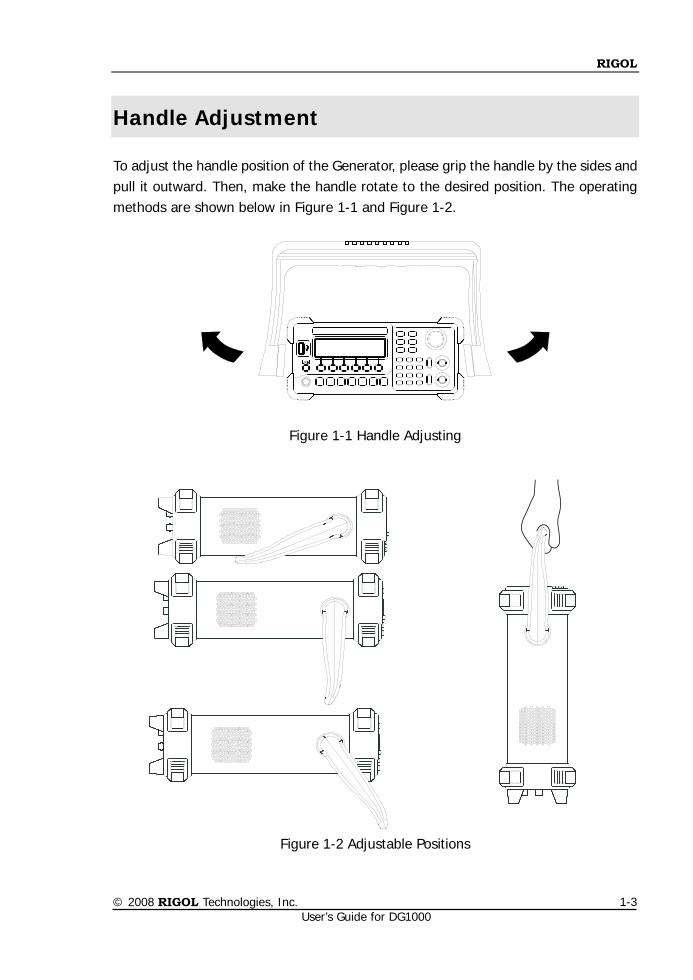
Handle Adjustment
To adjust the handle position of the Generator, please grip the handle by the sides and pull it outward. Then, make the handle rotate to the desired position. The operating methods are shown below in Figure 1-1 and Figure 1-2.
Figure 1-1 Handle Adjusting
Figure 1-2 Adjustable Positions
RIGOL
© 2008 RIGOL Technologies, Inc. User’s Guide for DG1000
1-4
The Front/Rear Panel
When you get a new DG1000 series Dual-Channel Function/Arbitrary Waveform Generator, first you need to know how to operate the front/ Rear panel correctly. This chapter will make a brief introduction and description for the operation and functions of the Front/ Rear Panel.
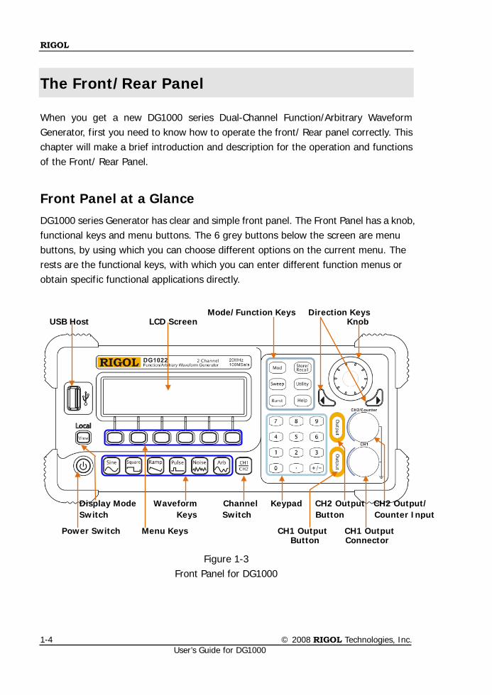
Front Panel at a Glance DG1000 series Generator has clear and simple front panel. The Front Panel has a knob, functional keys and menu buttons. The 6 grey buttons below the screen are menu buttons, by using which you can choose different options on the current menu. The rests are the functional keys, with which you can enter different function menus or obtain specific functional applications directly.
Figure 1-3 Front Panel for DG1000
Power Switch Menu Keys CH1 Output CH1 Output Button Connector
Display Mode Waveform Channel Keypad CH2 Output CH2 Output/ Switch Keys Switch Button Counter Input
Mode/Function Keys Direction Keys USB Host LCD Screen Knob
RIGOL
© 2008 RIGOL Technologies, Inc. User’s Guide for DG1000
1-5
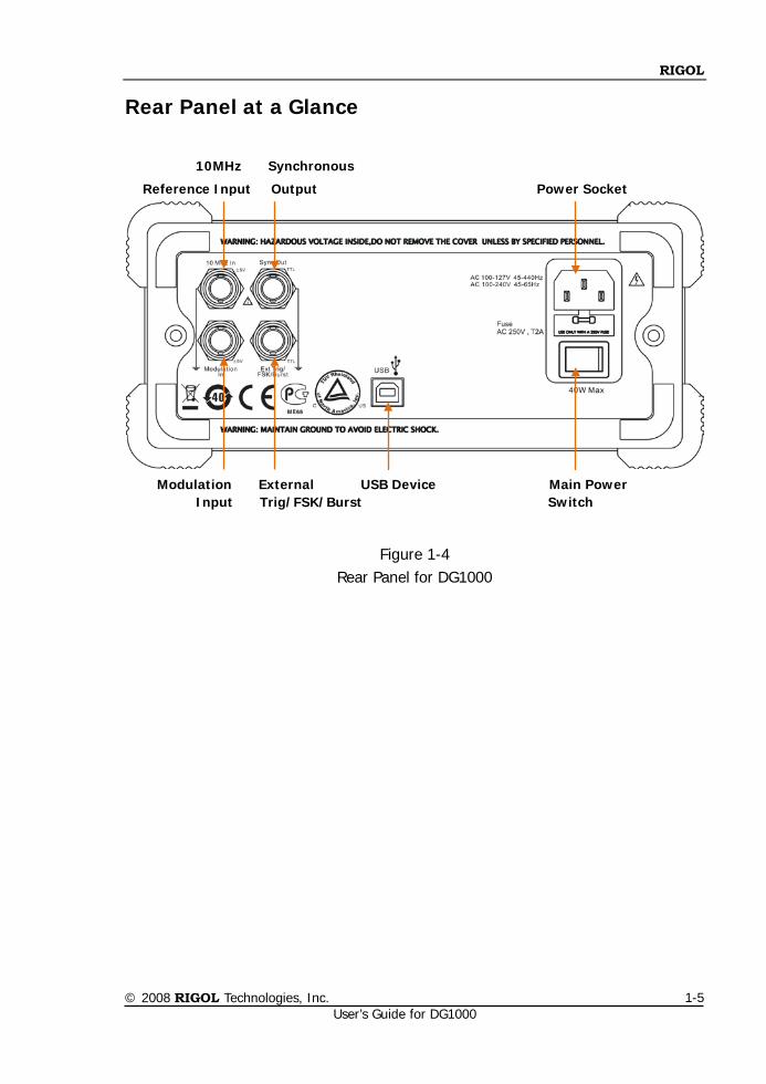
Rear Panel at a Glance
Figure 1-4 Rear Panel for DG1000
10MHz Synchronous
Reference Input Output Power Socket
Modulation External USB Device Main Power Input Trig/FSK/Burst Switch
RIGOL
© 2008 RIGOL Technologies, Inc. User’s Guide for DG1000
1-6
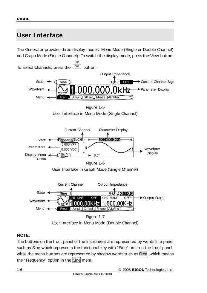
User Interface
The Generator provides three display modes: Menu Mode (Single or Double Channel) and Graph Mode (Single Channel). To switch the display mode, press the View button.
To select Channels, press the CH1
CH2 button.
Figure 1-5 User Interface in Menu Mode (Single Channel)
Figure 1-6 User Interface in Graph Mode (Single Channel)
Figure 1-7 User Interface in Menu Mode (Double Channel)
NOTE: The buttons on the front panel of the instrument are represented by words in a pane, such as Sine which represents the functional key with “Sine” on it on the front panel, while the menu buttons are represented by shadow words such as Freq, which means the “Frequency” option in the Sine menu.
Waveform
State
Menu
Parameter Display
Current Channel Sign
Output Impedance
Current Channel Output Impedance
Output State
Waveform
Menu
State
Parameters
Display Menu Button
Waveform Display
Current Channel Parameter Display
State
RIGOL
© 2008 RIGOL Technologies, Inc. User’s Guide for DG1000
1-7
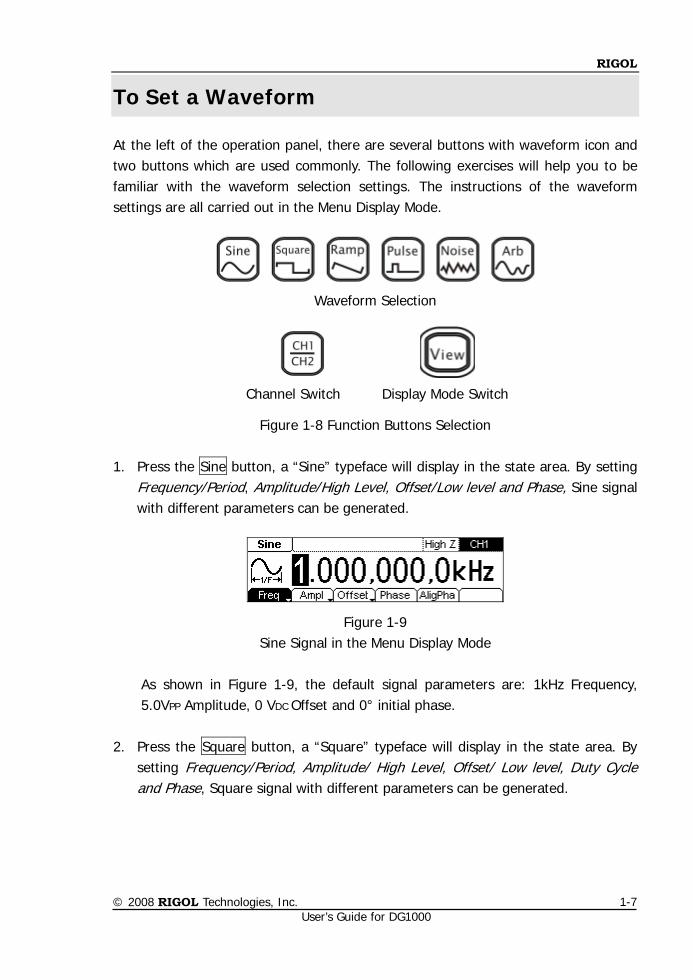
To Set a Waveform
At the left of the operation panel, there are several buttons with waveform icon and two buttons which are used commonly. The following exercises will help you to be familiar with the waveform selection settings. The instructions of the waveform settings are all carried out in the Menu Display Mode.
Waveform Selection
Channel Switch Display Mode Switch
Figure 1-8 Function Buttons Selection
1. Press the Sine button, a “Sine” typeface will display in the state area. By setting Frequency/Period, Amplitude/High Level, Offset/Low level and Phase, Sine signal with different parameters can be generated.
Figure 1-9 Sine Signal in the Menu Display Mode
As shown in Figure 1-9, the default signal parameters are: 1kHz Frequency, 5.0VPP Amplitude, 0 VDC Offset and 0° initial phase.
2. Press the Square button, a “Square” typeface will display in the state area. By setting Frequency/Period, Amplitude/ High Level, Offset/ Low level, Duty Cycle and Phase, Square signal with different parameters can be generated.
RIGOL
© 2008 RIGOL Technologies, Inc. User’s Guide for DG1000
1-8
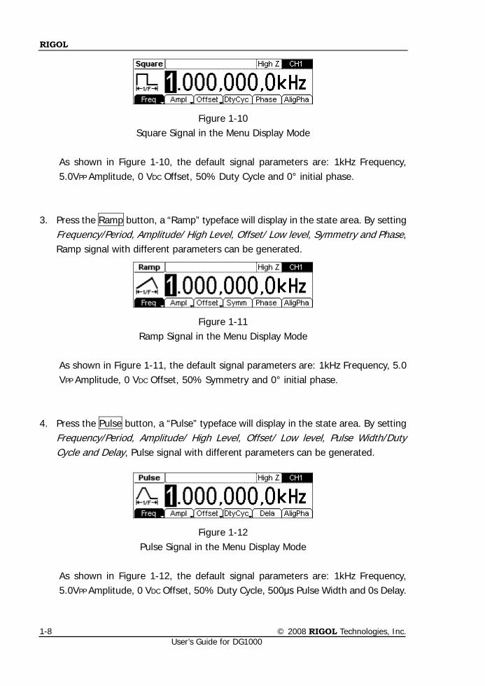
Figure 1-10 Square Signal in the Menu Display Mode
As shown in Figure 1-10, the default signal parameters are: 1kHz Frequency, 5.0VPP Amplitude, 0 VDC Offset, 50% Duty Cycle and 0° initial phase.
3. Press the Ramp button, a “Ramp” typeface will display in the state area. By setting
Frequency/Period, Amplitude/ High Level, Offset/ Low level, Symmetry and Phase, Ramp signal with different parameters can be generated.
Figure 1-11 Ramp Signal in the Menu Display Mode
As shown in Figure 1-11, the default signal parameters are: 1kHz Frequency, 5.0 VPP Amplitude, 0 VDC Offset, 50% Symmetry and 0° initial phase.
4. Press the Pulse button, a “Pulse” typeface will display in the state area. By setting
Frequency/Period, Amplitude/ High Level, Offset/ Low level, Pulse Width/Duty Cycle and Delay, Pulse signal with different parameters can be generated.
Figure 1-12 Pulse Signal in the Menu Display Mode
As shown in Figure 1-12, the default signal parameters are: 1kHz Frequency, 5.0VPP Amplitude, 0 VDC Offset, 50% Duty Cycle, 500μs Pulse Width and 0s Delay.
RIGOL
© 2008 RIGOL Technologies, Inc. User’s Guide for DG1000
1-9
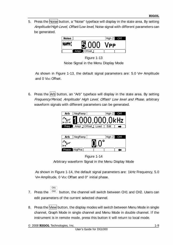
5. Press the Noise button, a “Noise” typeface will display in the state area. By setting Amplitude/High Level, Offset/Low level, Noise signal with different parameters can be generated.
Figure 1-13 Noise Signal in the Menu Display Mode
As shown in Figure 1-13, the default signal parameters are: 5.0 VPP Amplitude and 0 VDC Offset.
6. Press the Arb button, an “Arb” typeface will display in the state area. By setting
Frequency/Period, Amplitude/ High Level, Offset/ Low level and Phase, arbitrary waveform signals with different parameters can be generated.
Figure 1-14 Arbitrary waveform Signal in the Menu Display Mode
As shown in Figure 1-14, the default signal parameters are: 1kHz Frequency, 5.0 VPP Amplitude, 0 VDC Offset and 0° initial phase.
7. Press the CH1
CH2 button, the channel will switch between CH1 and CH2. Users can
edit parameters of the current selected channel. 8. Press the View button, the display modes will switch between Menu Mode in single
channel, Graph Mode in single channel and Menu Mode in double channel. If the instrument is in remote mode, press this button it will return to local mode.
RIGOL
© 2008 RIGOL Technologies, Inc. User’s Guide for DG1000
1-10
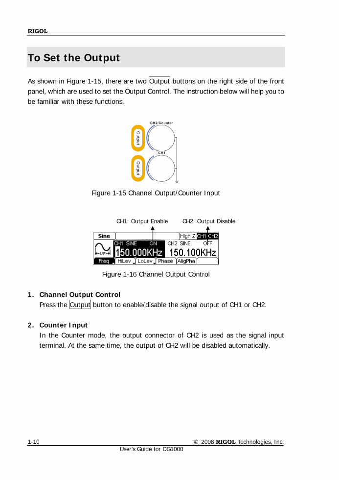
To Set the Output
As shown in Figure 1-15, there are two Output buttons on the right side of the front panel, which are used to set the Output Control. The instruction below will help you to be familiar with these functions.
Figure 1-15 Channel Output/Counter Input
Figure 1-16 Channel Output Control 1. Channel Output Control
Press the Output button to enable/disable the signal output of CH1 or CH2.
2. Counter Input In the Counter mode, the output connector of CH2 is used as the signal input terminal. At the same time, the output of CH2 will be disabled automatically.
CH1: Output Enable CH2: Output Disable
RIGOL
© 2008 RIGOL Technologies, Inc. User’s Guide for DG1000
1-11
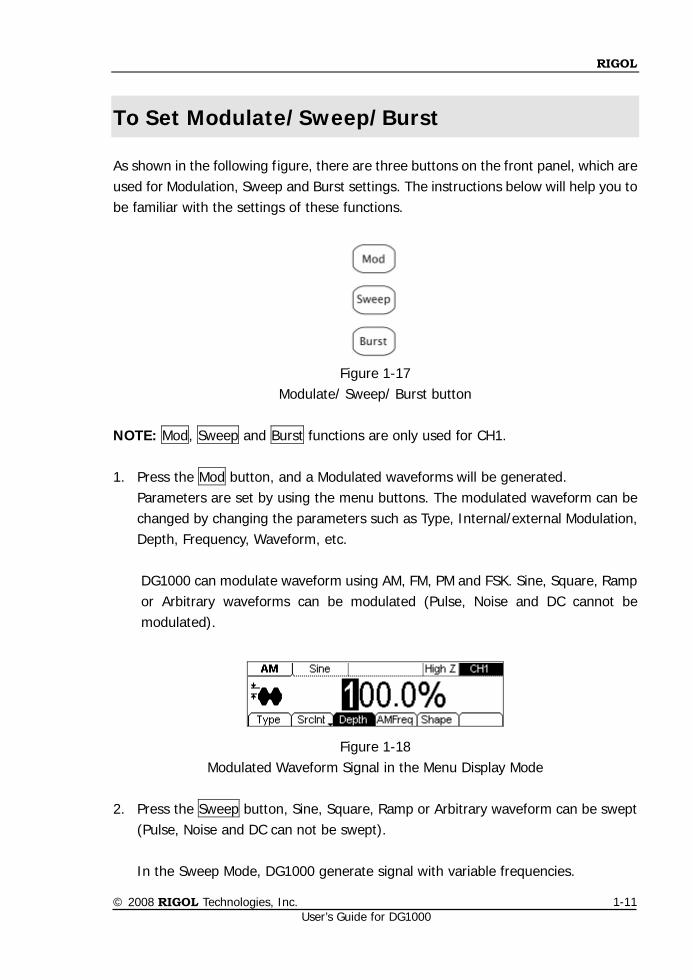
To Set Modulate/Sweep/Burst
As shown in the following figure, there are three buttons on the front panel, which are used for Modulation, Sweep and Burst settings. The instructions below will help you to be familiar with the settings of these functions.
Figure 1-17
Modulate/ Sweep/ Burst button
NOTE: Mod, Sweep and Burst functions are only used for CH1. 1. Press the Mod button, and a Modulated waveforms will be generated.
Parameters are set by using the menu buttons. The modulated waveform can be changed by changing the parameters such as Type, Internal/external Modulation, Depth, Frequency, Waveform, etc.
DG1000 can modulate waveform using AM, FM, PM and FSK. Sine, Square, Ramp or Arbitrary waveforms can be modulated (Pulse, Noise and DC cannot be modulated).
Figure 1-18 Modulated Waveform Signal in the Menu Display Mode
2. Press the Sweep button, Sine, Square, Ramp or Arbitrary waveform can be swept
(Pulse, Noise and DC can not be swept). In the Sweep Mode, DG1000 generate signal with variable frequencies.
RIGOL
© 2008 RIGOL Technologies, Inc. User’s Guide for DG1000
1-12
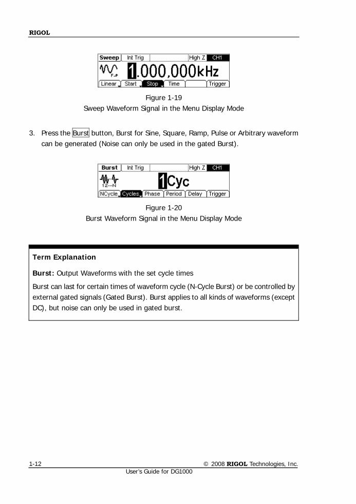
Figure 1-19 Sweep Waveform Signal in the Menu Display Mode
3. Press the Burst button, Burst for Sine, Square, Ramp, Pulse or Arbitrary waveform can be generated (Noise can only be used in the gated Burst).
Figure 1-20 Burst Waveform Signal in the Menu Display Mode
Term Explanation
Burst: Output Waveforms with the set cycle times
Burst can last for certain times of waveform cycle (N-Cycle Burst) or be controlled by external gated signals (Gated Burst). Burst applies to all kinds of waveforms (except DC), but noise can only be used in gated burst.
RIGOL
© 2008 RIGOL Technologies, Inc. User’s Guide for DG1000
1-13
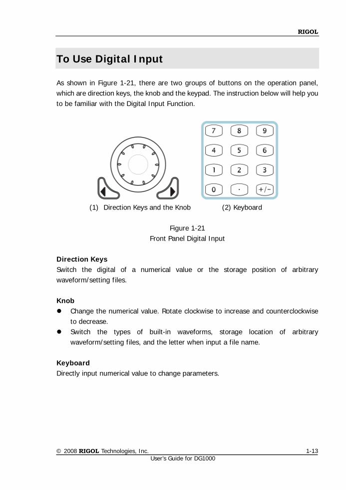
To Use Digital Input
As shown in Figure 1-21, there are two groups of buttons on the operation panel, which are direction keys, the knob and the keypad. The instruction below will help you to be familiar with the Digital Input Function.
(1) Direction Keys and the Knob (2) Keyboard
Figure 1-21
Front Panel Digital Input
Direction Keys Switch the digital of a numerical value or the storage position of arbitrary waveform/setting files.
Knob Change the numerical value. Rotate clockwise to increase and counterclockwise
to decrease. Switch the types of built-in waveforms, storage location of arbitrary
waveform/setting files, and the letter when input a file name.
Keyboard Directly input numerical value to change parameters.
RIGOL
© 2008 RIGOL Technologies, Inc. User’s Guide for DG1000
1-14
To Use Store/Utility/Help Function
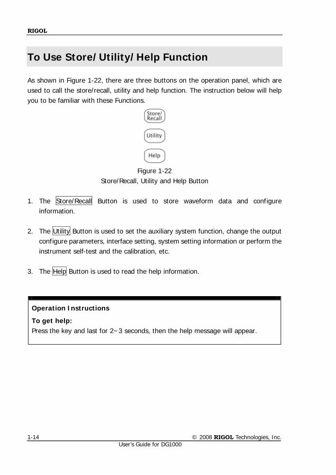
As shown in Figure 1-22, there are three buttons on the operation panel, which are used to call the store/recall, utility and help function. The instruction below will help you to be familiar with these Functions.
Figure 1-22
Store/Recall, Utility and Help Button 1. The Store/Recall Button is used to store waveform data and configure
information. 2. The Utility Button is used to set the auxiliary system function, change the output
configure parameters, interface setting, system setting information or perform the instrument self-test and the calibration, etc.
3. The Help Button is used to read the help information.
Operation Instructions
To get help: Press the key and last for 2~3 seconds, then the help message will appear.
RIGOL
© 2008 RIGOL Technologies, Inc. User’s Guide for DG1000
2-1
Chapter 2 Operating Your Generator
By now you have got a brief understanding of DG1000 with the front/rear panel, every function control area and keys.
This chapter covers the following topics:
To Set Basic Waveforms To Set Sine Waveform To Set Square Waveform To Set Ramp Waveform To Set Pulse Waveform To Set Noise Waveform
To Set Arbitrary Waveforms To Select Arbitrary Waveform
To Edit Arbitrary Waveform
To Set Modulated Waveforms To Set AM Waveform To Set FM Waveform To Set FSK Waveform To Set PM Waveform
To Generate Sweep Signal To Generate Burst Signal To Store and Recall
To Set the Utility Function To Set the Sync Output Basic Setting of the Two Channels Channel Coupling Settings To Set the Counter System Settings I/O Settings Test/Cal Settings Power Amplifier Settings
To Use the Help System
RIGOL
© 2008 RIGOL Technologies, Inc. User’s Guide for DG1000
2-2
To Set Basic Waveforms
To Set Sine Waveform
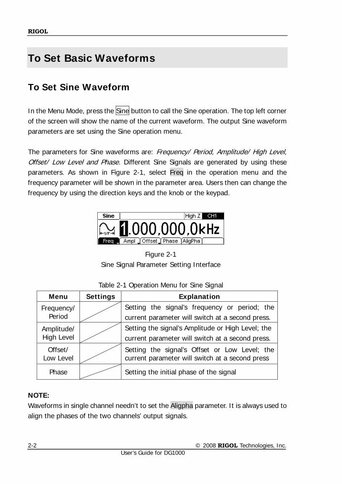
In the Menu Mode, press the Sine button to call the Sine operation. The top left corner of the screen will show the name of the current waveform. The output Sine waveform parameters are set using the Sine operation menu. The parameters for Sine waveforms are: Frequency/ Period, Amplitude/ High Level, Offset/ Low Level and Phase. Different Sine Signals are generated by using these parameters. As shown in Figure 2-1, select Freq in the operation menu and the frequency parameter will be shown in the parameter area. Users then can change the frequency by using the direction keys and the knob or the keypad.
Figure 2-1 Sine Signal Parameter Setting Interface
Table 2-1 Operation Menu for Sine Signal
NOTE: Waveforms in single channel needn’t to set the Aligpha parameter. It is always used to align the phases of the two channels’ output signals.
Menu Settings Explanation
Frequency/Period
Setting the signal’s frequency or period; the current parameter will switch at a second press.
Amplitude/ High Level
Setting the signal’s Amplitude or High Level; the current parameter will switch at a second press.
Offset/ Low Level
Setting the signal’s Offset or Low Level; the current parameter will switch at a second press
Phase Setting the initial phase of the signal
RIGOL
© 2008 RIGOL Technologies, Inc. User’s Guide for DG1000
2-3
To Set the Output Frequency/Period
1. Press Sine Freq/Period Freq, to set the frequency parameter.
The frequency shown on the screen is the default value when the instrument is powered or the set value beforehand. When setting the function, if the current value is valid for the new waveform, it will be used sequentially. If you want to set the period for the waveform, press Freq/Period button again, switch to the Period parameter (The current operation is displayed in inverse color).
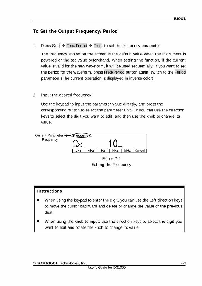
2. Input the desired frequency.
Use the keypad to input the parameter value directly, and press the corresponding button to select the parameter unit. Or you can use the direction keys to select the digit you want to edit, and then use the knob to change its value.
Figure 2-2 Setting the Frequency
Instructions
When using the keypad to enter the digit, you can use the Left direction keys to move the cursor backward and delete or change the value of the previous digit.
When using the knob to input, use the direction keys to select the digit you want to edit and rotate the knob to change its value.
Current Parameter: Frequency
RIGOL
© 2008 RIGOL Technologies, Inc. User’s Guide for DG1000
2-4
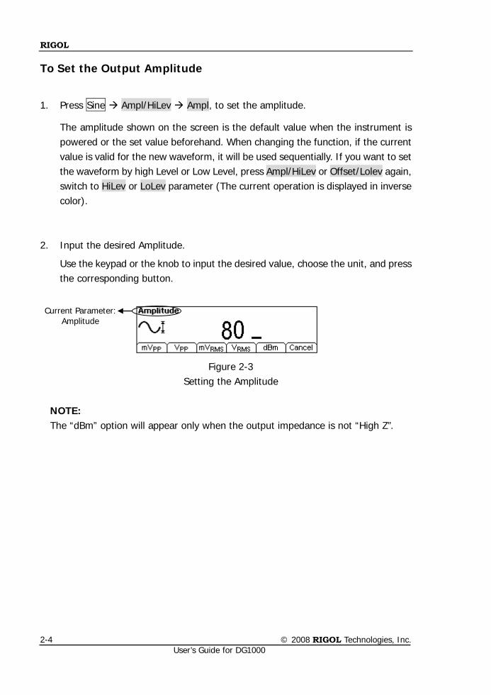
To Set the Output Amplitude
1. Press Sine Ampl/HiLev Ampl, to set the amplitude.
The amplitude shown on the screen is the default value when the instrument is powered or the set value beforehand. When changing the function, if the current value is valid for the new waveform, it will be used sequentially. If you want to set the waveform by high Level or Low Level, press Ampl/HiLev or Offset/Lolev again, switch to HiLev or LoLev parameter (The current operation is displayed in inverse color).
2. Input the desired Amplitude.
Use the keypad or the knob to input the desired value, choose the unit, and press the corresponding button.
Figure 2-3 Setting the Amplitude
NOTE: The “dBm” option will appear only when the output impedance is not “High Z”.
Current Parameter: Amplitude
RIGOL
© 2008 RIGOL Technologies, Inc. User’s Guide for DG1000
2-5
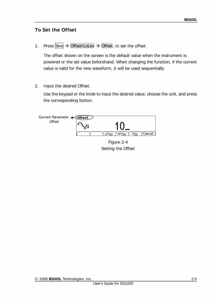
To Set the Offset
1. Press Sine Offset/LoLev Offset, to set the offset.
The offset shown on the screen is the default value when the instrument is powered or the set value beforehand. When changing the function, if the current value is valid for the new waveform, it will be used sequentially.
2. Input the desired Offset.
Use the keypad or the knob to input the desired value, choose the unit, and press the corresponding button.
Figure 2-4 Setting the Offset
Current Parameter: Offset
RIGOL
© 2008 RIGOL Technologies, Inc. User’s Guide for DG1000
2-6
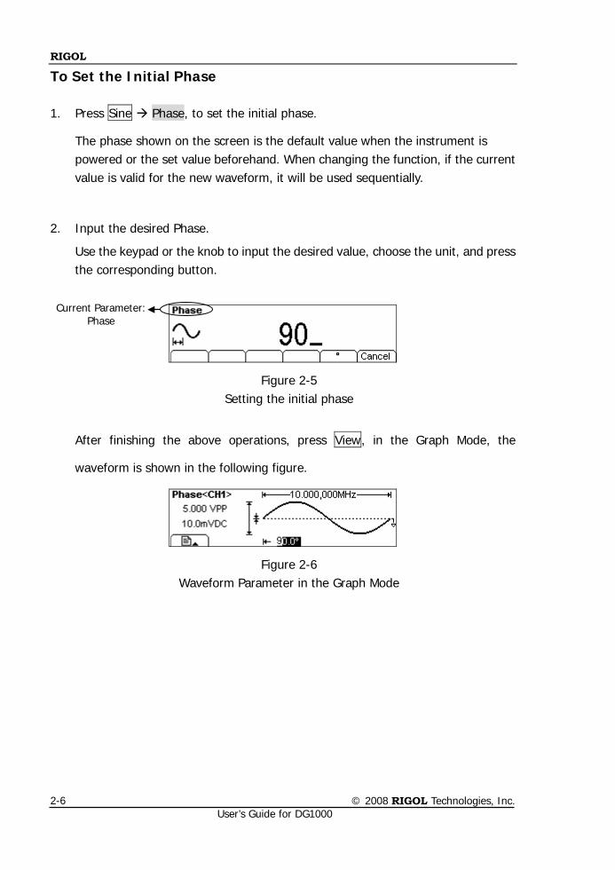
To Set the Initial Phase
1. Press Sine Phase, to set the initial phase.
The phase shown on the screen is the default value when the instrument is powered or the set value beforehand. When changing the function, if the current value is valid for the new waveform, it will be used sequentially.
2. Input the desired Phase.
Use the keypad or the knob to input the desired value, choose the unit, and press the corresponding button.
Figure 2-5 Setting the initial phase
After finishing the above operations, press View, in the Graph Mode, the
waveform is shown in the following figure.
Figure 2-6 Waveform Parameter in the Graph Mode
Current Parameter: Phase
RIGOL
© 2008 RIGOL Technologies, Inc. User’s Guide for DG1000
2-7
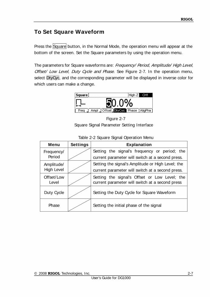
To Set Square Waveform
Press the Square button, in the Normal Mode, the operation menu will appear at the bottom of the screen. Set the Square parameters by using the operation menu. The parameters for Square waveforms are: Frequency/ Period, Amplitude/ High Level, Offset/ Low Level, Duty Cycle and Phase. See Figure 2-7. In the operation menu, select DtyCyc, and the corresponding parameter will be displayed in inverse color for which users can make a change.
Figure 2-7
Square Signal Parameter Setting Interface
Table 2-2 Square Signal Operation Menu
Menu Settings Explanation
Frequency/ Period
Setting the signal’s frequency or period; the current parameter will switch at a second press.
Amplitude/ High Level
Setting the signal’s Amplitude or High Level; the current parameter will switch at a second press.
Offset/Low Level
Setting the signal’s Offset or Low Level; the current parameter will switch at a second press
Duty Cycle Setting the Duty Cycle for Square Waveform
Phase
Setting the initial phase of the signal
RIGOL
© 2008 RIGOL Technologies, Inc. User’s Guide for DG1000
2-8
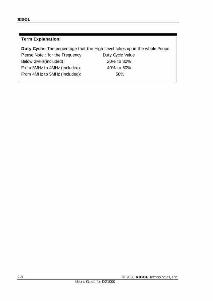
Term Explanation:
Duty Cycle: The percentage that the High Level takes up in the whole Period. Please Note : for the Frequency Duty Cycle Value Below 3MHz(included): 20% to 80% From 3MHz to 4MHz (included): 40% to 60% From 4MHz to 5MHz (included): 50%
RIGOL
© 2008 RIGOL Technologies, Inc. User’s Guide for DG1000
2-9
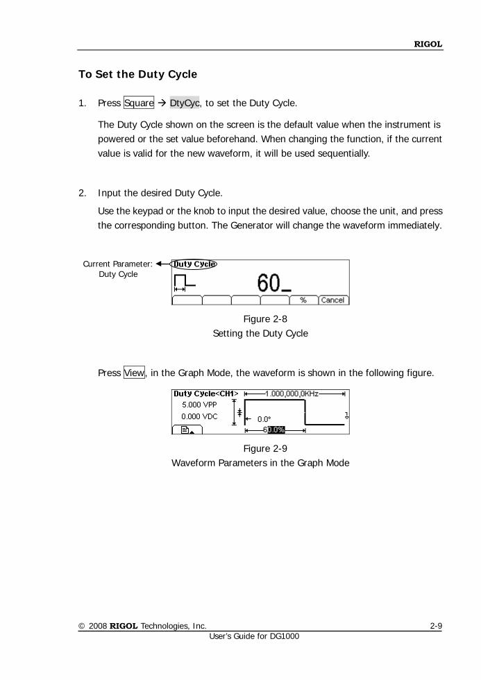
To Set the Duty Cycle
1. Press Square DtyCyc, to set the Duty Cycle.
The Duty Cycle shown on the screen is the default value when the instrument is powered or the set value beforehand. When changing the function, if the current value is valid for the new waveform, it will be used sequentially.
2. Input the desired Duty Cycle.
Use the keypad or the knob to input the desired value, choose the unit, and press the corresponding button. The Generator will change the waveform immediately.
Figure 2-8 Setting the Duty Cycle
Press View, in the Graph Mode, the waveform is shown in the following figure.
Figure 2-9 Waveform Parameters in the Graph Mode
Current Parameter: Duty Cycle
RIGOL
© 2008 RIGOL Technologies, Inc. User’s Guide for DG1000
2-10
To Set Ramp Waveform
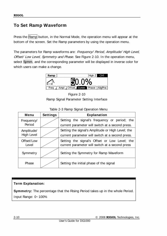
Press the Ramp button, in the Normal Mode, the operation menu will appear at the bottom of the screen. Set the Ramp parameters by using the operation menu. The parameters for Ramp waveforms are: Frequency/ Period, Amplitude/ High Level, Offset/ Low Level, Symmetry and Phase. See Figure 2-10. In the operation menu, select Symm, and the corresponding parameter will be displayed in inverse color for which users can make a change.
Figure 2-10
Ramp Signal Parameter Setting Interface
Table 2-3 Ramp Signal Operation Menu
Menu Settings Explanation
Frequency/ Period
Setting the signal’s frequency or period; the current parameter will switch at a second press.
Amplitude/ High Level
Setting the signal’s Amplitude or High Level; the current parameter will switch at a second press.
Offset/Low Level
Setting the signal’s Offset or Low Level; the current parameter will switch at a second press
Symmetry Setting the Symmetry for Ramp Waveform
Phase
Setting the initial phase of the signal
Term Explanation:
Symmetry: The percentage that the Rising Period takes up in the whole Period.
Input Range: 0~100%
RIGOL
© 2008 RIGOL Technologies, Inc. User’s Guide for DG1000
2-11
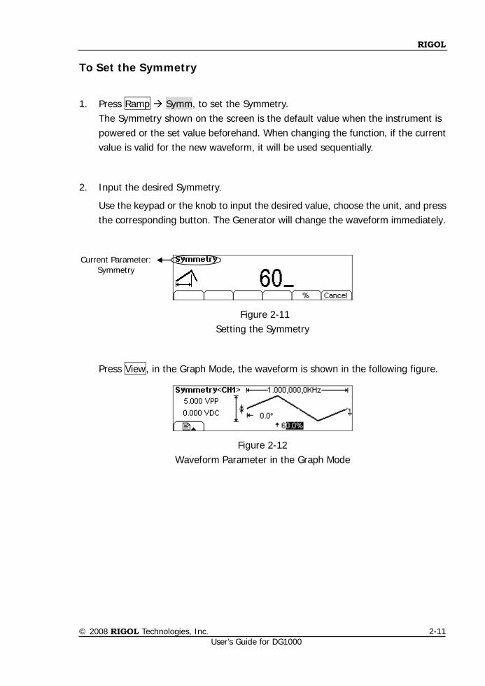
To Set the Symmetry
1. Press Ramp Symm, to set the Symmetry.
The Symmetry shown on the screen is the default value when the instrument is powered or the set value beforehand. When changing the function, if the current value is valid for the new waveform, it will be used sequentially.
2. Input the desired Symmetry.
Use the keypad or the knob to input the desired value, choose the unit, and press the corresponding button. The Generator will change the waveform immediately.
Figure 2-11 Setting the Symmetry
Press View, in the Graph Mode, the waveform is shown in the following figure.
Figure 2-12 Waveform Parameter in the Graph Mode
Current Parameter: Symmetry
RIGOL
© 2008 RIGOL Technologies, Inc. User’s Guide for DG1000
2-12
To Set Pulse Waveform
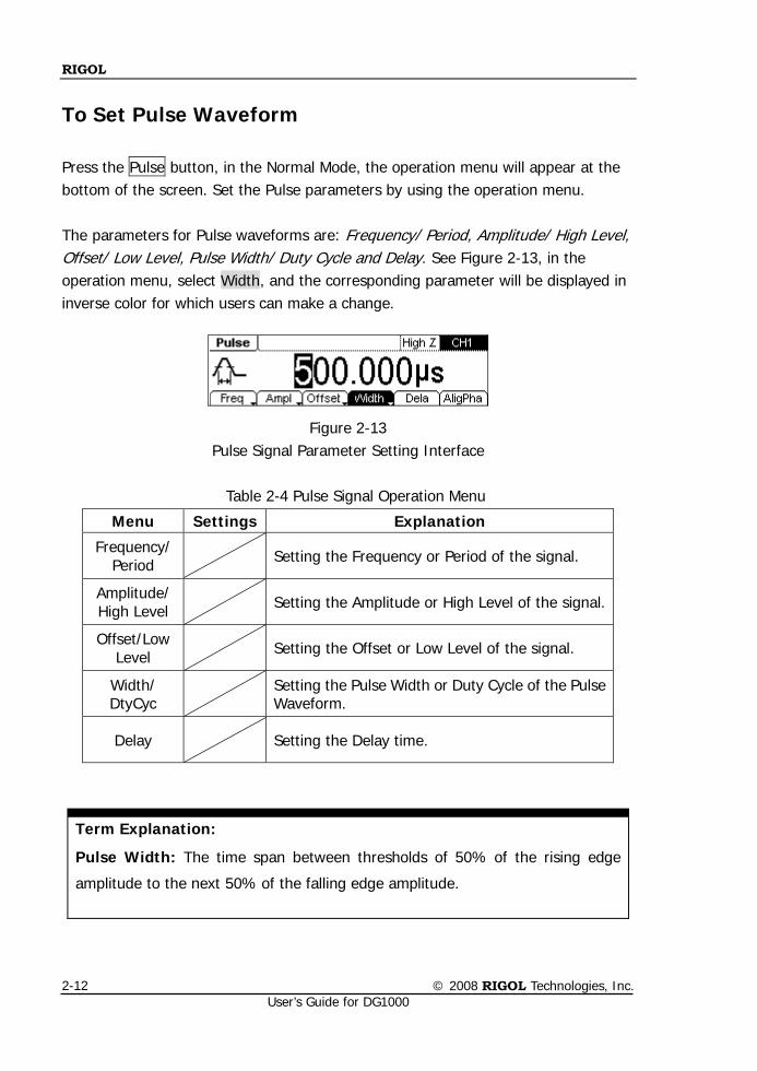
Press the Pulse button, in the Normal Mode, the operation menu will appear at the bottom of the screen. Set the Pulse parameters by using the operation menu. The parameters for Pulse waveforms are: Frequency/ Period, Amplitude/ High Level, Offset/ Low Level, Pulse Width/ Duty Cycle and Delay. See Figure 2-13, in the operation menu, select Width, and the corresponding parameter will be displayed in inverse color for which users can make a change.
Figure 2-13
Pulse Signal Parameter Setting Interface
Table 2-4 Pulse Signal Operation Menu
Term Explanation:
Pulse Width: The time span between thresholds of 50% of the rising edge
amplitude to the next 50% of the falling edge amplitude.
Menu Settings Explanation
Frequency/ Period
Setting the Frequency or Period of the signal.
Amplitude/ High Level
Setting the Amplitude or High Level of the signal.
Offset/Low Level
Setting the Offset or Low Level of the signal.
Width/ DtyCyc Setting the Pulse Width or Duty Cycle of the Pulse
Waveform.
Delay Setting the Delay time.
RIGOL
© 2008 RIGOL Technologies, Inc. User’s Guide for DG1000
2-13
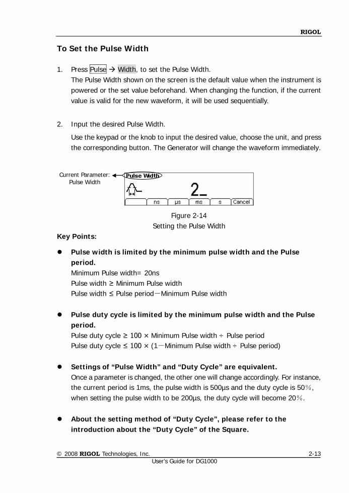
To Set the Pulse Width
1. Press Pulse Width, to set the Pulse Width. The Pulse Width shown on the screen is the default value when the instrument is powered or the set value beforehand. When changing the function, if the current value is valid for the new waveform, it will be used sequentially.
2. Input the desired Pulse Width.
Use the keypad or the knob to input the desired value, choose the unit, and press the corresponding button. The Generator will change the waveform immediately.
Figure 2-14 Setting the Pulse Width
Key Points:
Pulse width is limited by the minimum pulse width and the Pulse period. Minimum Pulse width= 20ns Pulse width ≥ Minimum Pulse width Pulse width ≤ Pulse period-Minimum Pulse width
Pulse duty cycle is limited by the minimum pulse width and the Pulse period. Pulse duty cycle ≥ 100 × Minimum Pulse width ÷ Pulse period Pulse duty cycle ≤ 100 × (1-Minimum Pulse width ÷ Pulse period)
Settings of “Pulse Width” and “Duty Cycle” are equivalent. Once a parameter is changed, the other one will change accordingly. For instance, the current period is 1ms, the pulse width is 500µs and the duty cycle is 50%, when setting the pulse width to be 200µs, the duty cycle will become 20%.
About the setting method of “Duty Cycle”, please refer to the introduction about the “Duty Cycle” of the Square.
Current Parameter: Pulse Width
RIGOL
© 2008 RIGOL Technologies, Inc. User’s Guide for DG1000
2-14
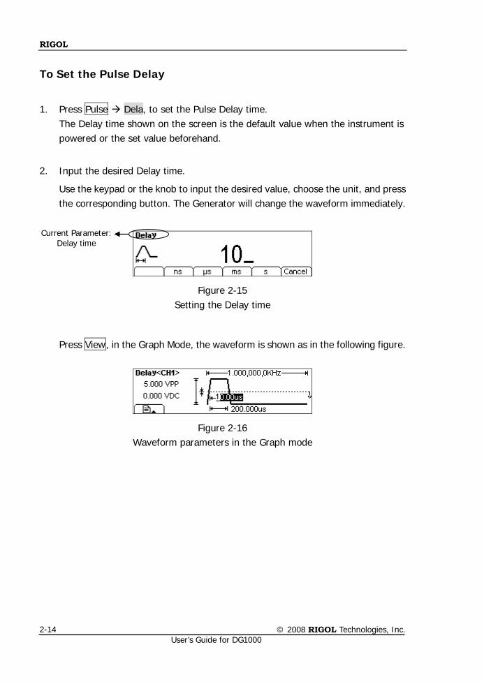
To Set the Pulse Delay
1. Press Pulse Dela, to set the Pulse Delay time. The Delay time shown on the screen is the default value when the instrument is powered or the set value beforehand.
2. Input the desired Delay time.
Use the keypad or the knob to input the desired value, choose the unit, and press the corresponding button. The Generator will change the waveform immediately.
Figure 2-15
Setting the Delay time
Press View, in the Graph Mode, the waveform is shown as in the following figure.
Figure 2-16 Waveform parameters in the Graph mode
Current Parameter: Delay time
RIGOL
© 2008 RIGOL Technologies, Inc. User’s Guide for DG1000
2-15
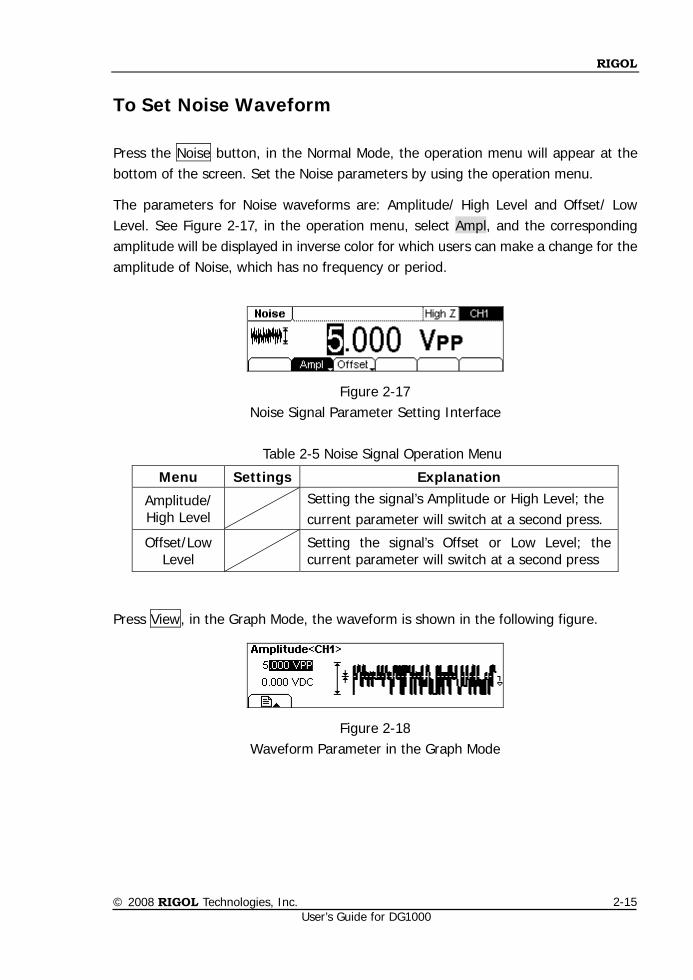
To Set Noise Waveform
Press the Noise button, in the Normal Mode, the operation menu will appear at the bottom of the screen. Set the Noise parameters by using the operation menu.
The parameters for Noise waveforms are: Amplitude/ High Level and Offset/ Low Level. See Figure 2-17, in the operation menu, select Ampl, and the corresponding amplitude will be displayed in inverse color for which users can make a change for the amplitude of Noise, which has no frequency or period.
Figure 2-17
Noise Signal Parameter Setting Interface
Table 2-5 Noise Signal Operation Menu
Press View, in the Graph Mode, the waveform is shown in the following figure.
Figure 2-18 Waveform Parameter in the Graph Mode
Menu Settings Explanation
Amplitude/ High Level
Setting the signal’s Amplitude or High Level; the current parameter will switch at a second press.
Offset/Low Level
Setting the signal’s Offset or Low Level; the current parameter will switch at a second press
RIGOL
© 2008 RIGOL Technologies, Inc. User’s Guide for DG1000
2-16
To Set Arbitrary Waveforms
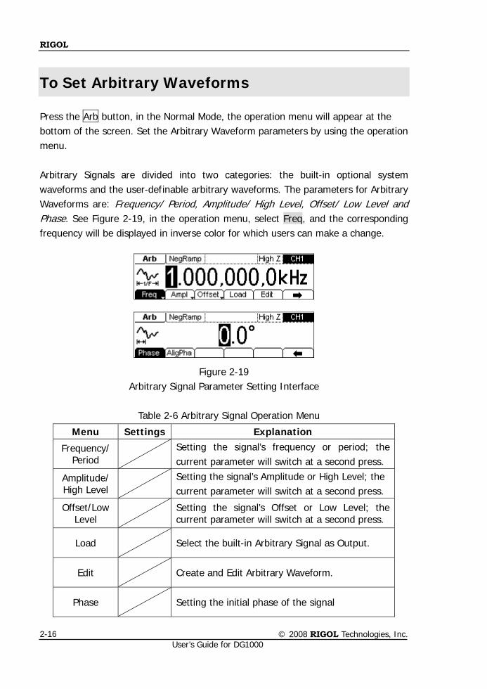
Press the Arb button, in the Normal Mode, the operation menu will appear at the bottom of the screen. Set the Arbitrary Waveform parameters by using the operation menu. Arbitrary Signals are divided into two categories: the built-in optional system waveforms and the user-definable arbitrary waveforms. The parameters for Arbitrary Waveforms are: Frequency/ Period, Amplitude/ High Level, Offset/ Low Level and Phase. See Figure 2-19, in the operation menu, select Freq, and the corresponding frequency will be displayed in inverse color for which users can make a change.
Figure 2-19
Arbitrary Signal Parameter Setting Interface
Table 2-6 Arbitrary Signal Operation Menu
Menu Settings Explanation
Frequency/ Period
Setting the signal’s frequency or period; the current parameter will switch at a second press.
Amplitude/ High Level
Setting the signal’s Amplitude or High Level; the current parameter will switch at a second press.
Offset/Low Level
Setting the signal’s Offset or Low Level; the current parameter will switch at a second press.
Load Select the built-in Arbitrary Signal as Output.
Edit Create and Edit Arbitrary Waveform.
Phase
Setting the initial phase of the signal
RIGOL
© 2008 RIGOL Technologies, Inc. User’s Guide for DG1000
2-17
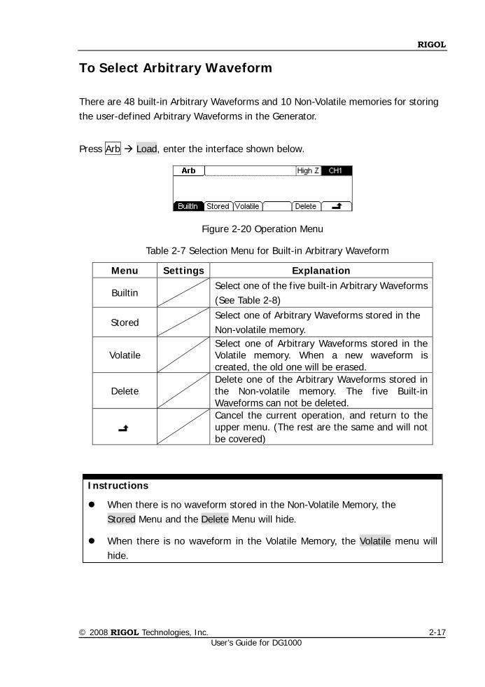
To Select Arbitrary Waveform
There are 48 built-in Arbitrary Waveforms and 10 Non-Volatile memories for storing the user-defined Arbitrary Waveforms in the Generator.
Press Arb Load, enter the interface shown below.
Figure 2-20 Operation Menu
Table 2-7 Selection Menu for Built-in Arbitrary Waveform
Instructions
When there is no waveform stored in the Non-Volatile Memory, the Stored Menu and the Delete Menu will hide.
When there is no waveform in the Volatile Memory, the Volatile menu will hide.
Menu Settings Explanation
Builtin Select one of the five built-in Arbitrary Waveforms
(See Table 2-8)
Stored Select one of Arbitrary Waveforms stored in the
Non-volatile memory.
Volatile Select one of Arbitrary Waveforms stored in the
Volatile memory. When a new waveform is created, the old one will be erased.
Delete Delete one of the Arbitrary Waveforms stored in the Non-volatile memory. The five Built-in Waveforms can not be deleted.
Cancel the current operation, and return to the upper menu. (The rest are the same and will not be covered)
RIGOL
© 2008 RIGOL Technologies, Inc. User’s Guide for DG1000
2-18
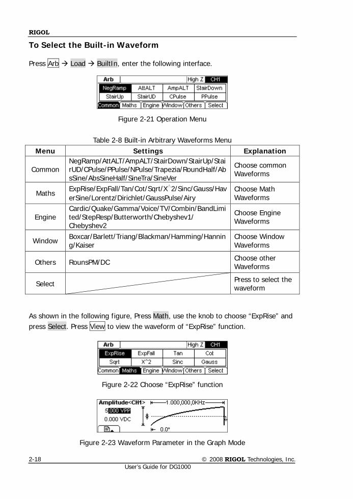
To Select the Built-in Waveform
Press Arb Load BuiltIn, enter the following interface.
Figure 2-21 Operation Menu
Table 2-8 Built-in Arbitrary Waveforms Menu Menu Settings Explanation
Common NegRamp/AttALT/AmpALT/StairDown/StairUp/StairUD/CPulse/PPulse/NPulse/Trapezia/RoundHalf/AbsSine/AbsSineHalf/SineTra/SineVer
Choose common Waveforms
Maths ExpRise/ExpFall/Tan/Cot/Sqrt/X∧2/Sinc/Gauss/HaverSine/Lorentz/Dirichlet/GaussPulse/Airy
Choose Math Waveforms
Engine Cardic/Quake/Gamma/Voice/TV/Combin/BandLimited/StepResp/Butterworth/Chebyshev1/ Chebyshev2
Choose Engine Waveforms
Window Boxcar/Barlett/Triang/Blackman/Hamming/Hanning/Kaiser
Choose Window Waveforms
Others RounsPM/DC Choose other Waveforms
Select Press to select the waveform
As shown in the following figure, Press Math, use the knob to choose “ExpRise” and press Select. Press View to view the waveform of “ExpRise” function.
Figure 2-22 Choose “ExpRise” function
Figure 2-23 Waveform Parameter in the Graph Mode
RIGOL
© 2008 RIGOL Technologies, Inc. User’s Guide for DG1000
2-19
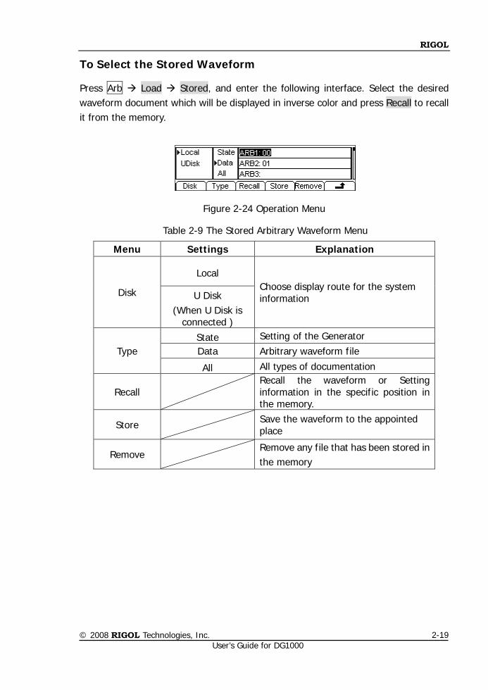
To Select the Stored Waveform
Press Arb Load Stored, and enter the following interface. Select the desired waveform document which will be displayed in inverse color and press Recall to recall it from the memory.
Figure 2-24 Operation Menu
Table 2-9 The Stored Arbitrary Waveform Menu
Menu Settings Explanation
Disk
Local Choose display route for the system information U Disk
(When U Disk is connected )
Type State Setting of the Generator Data Arbitrary waveform file
All All types of documentation
Recall Recall the waveform or Setting information in the specific position in the memory.
Store
Save the waveform to the appointed place
Remove Remove any file that has been stored in the memory
RIGOL
© 2008 RIGOL Technologies, Inc. User’s Guide for DG1000
2-20
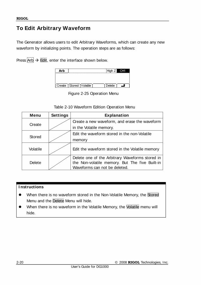
To Edit Arbitrary Waveform
The Generator allows users to edit Arbitrary Waveforms, which can create any new waveform by initializing points. The operation steps are as follows: Press Arb Edit, enter the interface shown below.
Figure 2-25 Operation Menu
Table 2-10 Waveform Edition Operation Menu
Instructions
When there is no waveform stored in the Non-Volatile Memory, the Stored Menu and the Delete Menu will hide.
When there is no waveform in the Volatile Memory, the Volatile menu will hide.
Menu Settings Explanation
Create Create a new waveform, and erase the waveform
in the Volatile memory.
Stored Edit the waveform stored in the non-Volatile
memory
Volatile
Edit the waveform stored in the Volatile memory
Delete Delete one of the Arbitrary Waveforms stored in the Non-volatile memory. But The five Built-in Waveforms can not be deleted.
RIGOL
© 2008 RIGOL Technologies, Inc. User’s Guide for DG1000
2-21
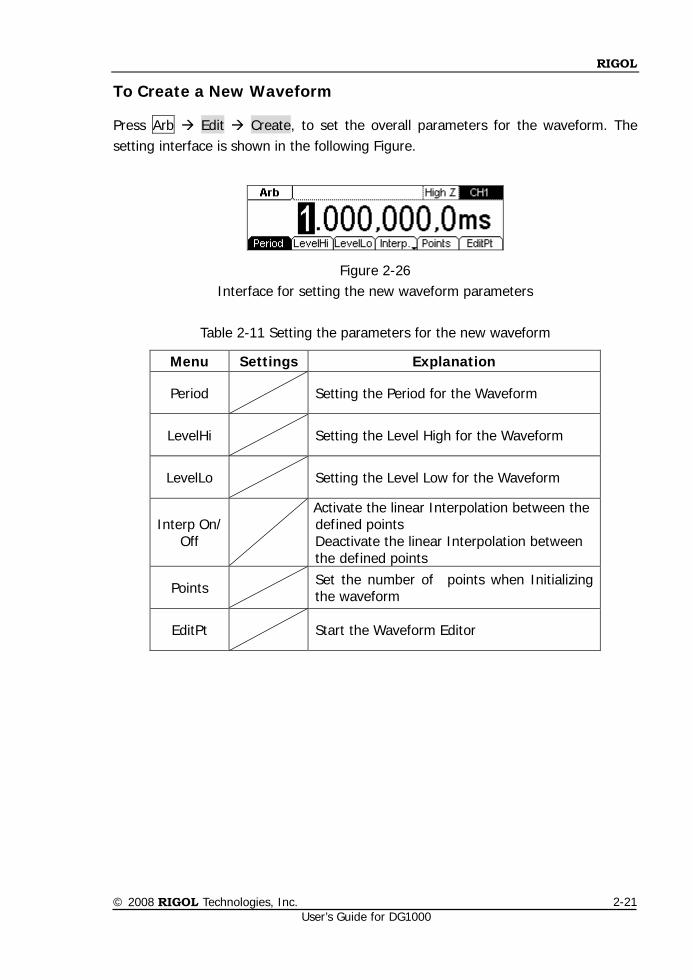
To Create a New Waveform
Press Arb Edit Create, to set the overall parameters for the waveform. The setting interface is shown in the following Figure.
Figure 2-26 Interface for setting the new waveform parameters
Table 2-11 Setting the parameters for the new waveform
Menu Settings Explanation
Period Setting the Period for the Waveform
LevelHi Setting the Level High for the Waveform
LevelLo Setting the Level Low for the Waveform
Interp On/ Off
Activate the linear Interpolation between the defined points Deactivate the linear Interpolation between the defined points
Points Set the number of points when Initializing the waveform
EditPt Start the Waveform Editor
RIGOL
© 2008 RIGOL Technologies, Inc. User’s Guide for DG1000
2-22
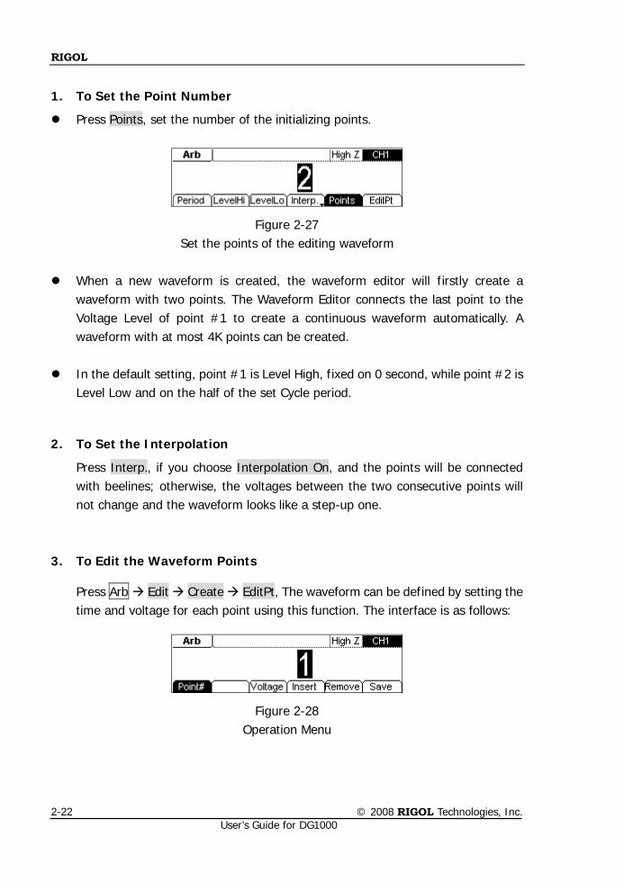
1. To Set the Point Number
Press Points, set the number of the initializing points.
Figure 2-27 Set the points of the editing waveform
When a new waveform is created, the waveform editor will firstly create a
waveform with two points. The Waveform Editor connects the last point to the Voltage Level of point #1 to create a continuous waveform automatically. A waveform with at most 4K points can be created.
In the default setting, point #1 is Level High, fixed on 0 second, while point #2 is
Level Low and on the half of the set Cycle period.
2. To Set the Interpolation
Press Interp., if you choose Interpolation On, and the points will be connected with beelines; otherwise, the voltages between the two consecutive points will not change and the waveform looks like a step-up one.
3. To Edit the Waveform Points
Press Arb Edit Create EditPt, The waveform can be defined by setting the time and voltage for each point using this function. The interface is as follows:
Figure 2-28 Operation Menu
RIGOL
© 2008 RIGOL Technologies, Inc. User’s Guide for DG1000
2-23
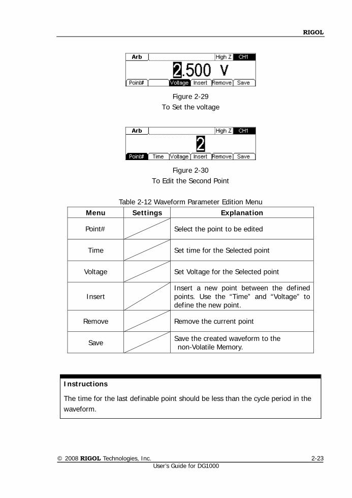
Figure 2-29 To Set the voltage
Figure 2-30 To Edit the Second Point
Table 2-12 Waveform Parameter Edition Menu
Menu Settings Explanation
Point# Select the point to be edited
Time Set time for the Selected point
Voltage Set Voltage for the Selected point
Insert Insert a new point between the defined points. Use the “Time” and “Voltage” to define the new point.
Remove Remove the current point
Save Save the created waveform to the non-Volatile Memory.
Instructions
The time for the last definable point should be less than the cycle period in the waveform.
RIGOL
© 2008 RIGOL Technologies, Inc. User’s Guide for DG1000
2-24
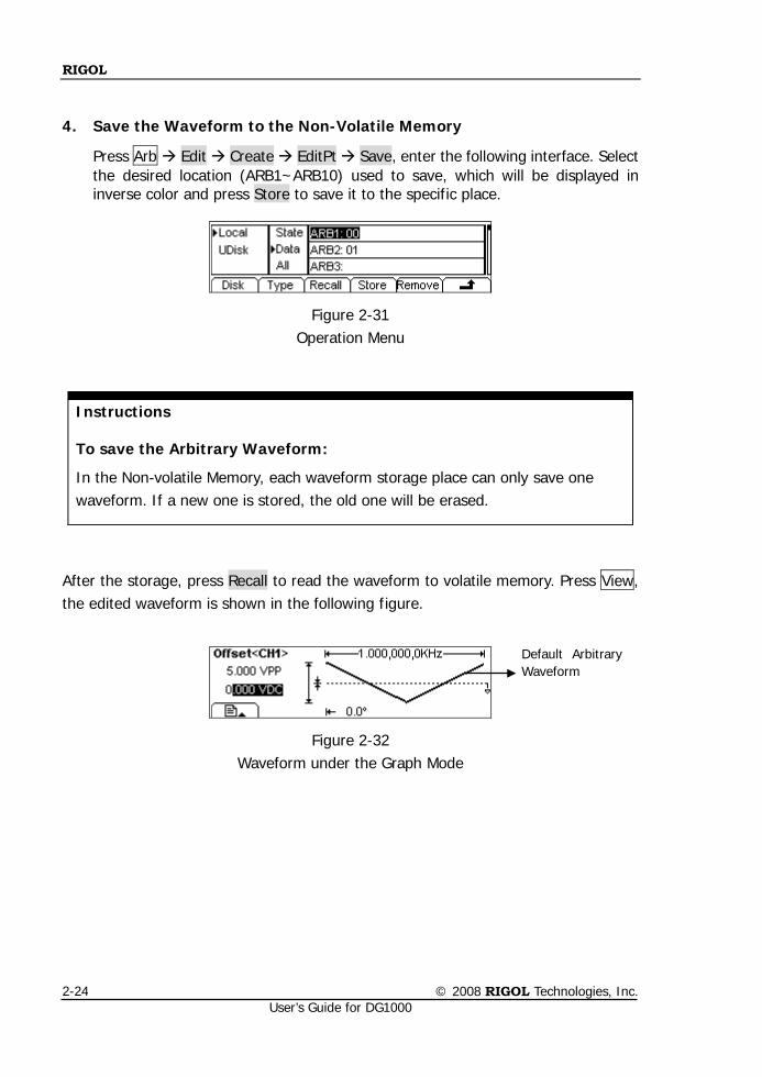
4. Save the Waveform to the Non-Volatile Memory
Press Arb Edit Create EditPt Save, enter the following interface. Select the desired location (ARB1~ARB10) used to save, which will be displayed in inverse color and press Store to save it to the specific place.
Figure 2-31 Operation Menu
Instructions
To save the Arbitrary Waveform:
In the Non-volatile Memory, each waveform storage place can only save one waveform. If a new one is stored, the old one will be erased.
After the storage, press Recall to read the waveform to volatile memory. Press View, the edited waveform is shown in the following figure.
Figure 2-32 Waveform under the Graph Mode
Default Arbitrary Waveform
RIGOL
© 2008 RIGOL Technologies, Inc. User’s Guide for DG1000
2-25
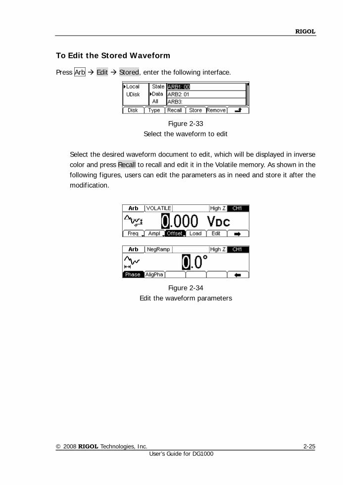
To Edit the Stored Waveform
Press Arb Edit Stored, enter the following interface.
Figure 2-33 Select the waveform to edit
Select the desired waveform document to edit, which will be displayed in inverse color and press Recall to recall and edit it in the Volatile memory. As shown in the following figures, users can edit the parameters as in need and store it after the modification.
Figure 2-34 Edit the waveform parameters
RIGOL
© 2008 RIGOL Technologies, Inc. User’s Guide for DG1000
2-26
To Set Modulated Waveforms
Use the Mod button to generate modulated waveform. DG1000 can generate AM, FM, FSK, PM modulated waveforms. The modulation parameters should be set in different types of modulation.
In AM, users can set the Source (Internal/ External), depth, Modulating Frequency, Modulating Waveform and Carrier Waveform;
In FM, users can set the Source (Internal/ External), Frequency Deviation, Modulating Waveform and Carrier Waveform;
In FSK, users can set the Source (Internal/ External), HopFreq, FSK Rate, and Carrier Waveform;
In PM, users can set the Source (Internal/ External), Phase Deviation, Modulating Frequency, Modulating Waveform and Carrier Waveform.
We will introduce how to set these parameters in details according to different types of modulation.
RIGOL
© 2008 RIGOL Technologies, Inc. User’s Guide for DG1000
2-27
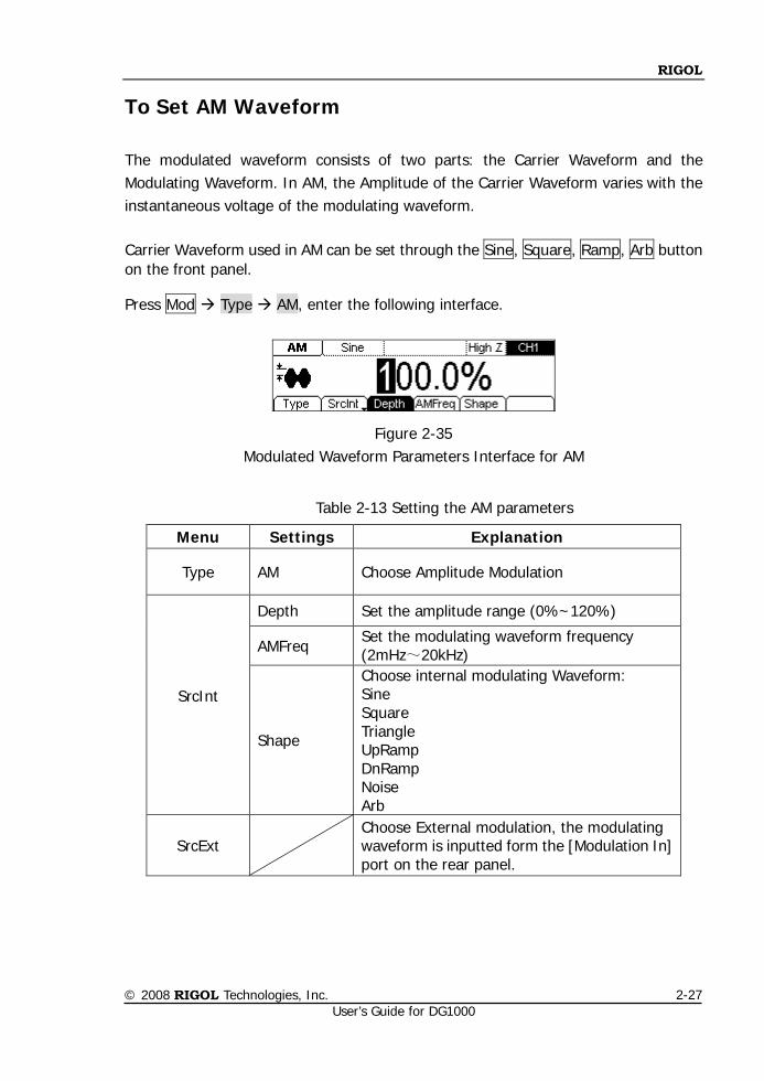
To Set AM Waveform
The modulated waveform consists of two parts: the Carrier Waveform and the Modulating Waveform. In AM, the Amplitude of the Carrier Waveform varies with the instantaneous voltage of the modulating waveform. Carrier Waveform used in AM can be set through the Sine, Square, Ramp, Arb button on the front panel.
Press Mod Type AM, enter the following interface.
Figure 2-35 Modulated Waveform Parameters Interface for AM
Table 2-13 Setting the AM parameters
Menu Settings Explanation
Type AM Choose Amplitude Modulation
SrcInt
Depth Set the amplitude range (0%~120%)
AMFreq Set the modulating waveform frequency (2mHz~20kHz)
Shape
Choose internal modulating Waveform: Sine Square Triangle UpRamp DnRamp Noise Arb
SrcExt Choose External modulation, the modulating waveform is inputted form the [Modulation In] port on the rear panel.
RIGOL
© 2008 RIGOL Technologies, Inc. User’s Guide for DG1000
2-28
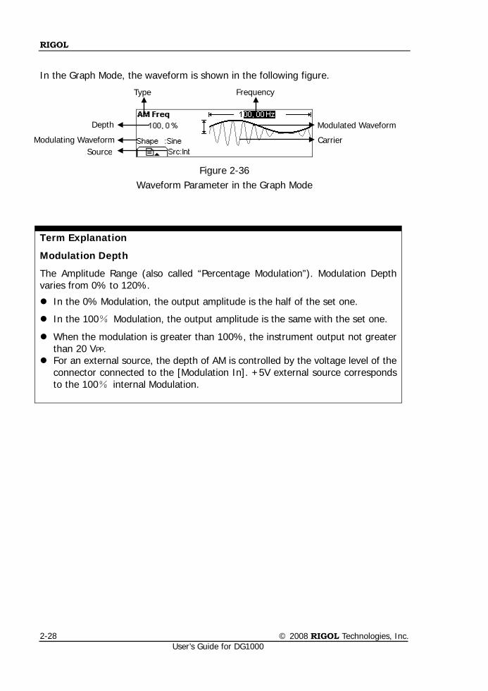
In the Graph Mode, the waveform is shown in the following figure.
Figure 2-36 Waveform Parameter in the Graph Mode
Term Explanation
Modulation Depth
The Amplitude Range (also called “Percentage Modulation”). Modulation Depth varies from 0% to 120%.
In the 0% Modulation, the output amplitude is the half of the set one.
In the 100% Modulation, the output amplitude is the same with the set one.
When the modulation is greater than 100%, the instrument output not greater than 20 VPP.
For an external source, the depth of AM is controlled by the voltage level of the connector connected to the [Modulation In]. +5V external source corresponds to the 100% internal Modulation.
Modulating Waveform
Depth
Carrier
Modulated Waveform
Source
Type Frequency
RIGOL
© 2008 RIGOL Technologies, Inc. User’s Guide for DG1000
2-29
To Set FM Waveform
The modulated waveform consists of two parts: the Carrier Waveform and the Modulating Waveform. In FM, the Frequency of the Carrier Waveform varies with the instantaneous voltage of the modulating waveform. Carrier Waveform used in FM can be set through the Sine, Square, Ramp, Arb button on the front panel.
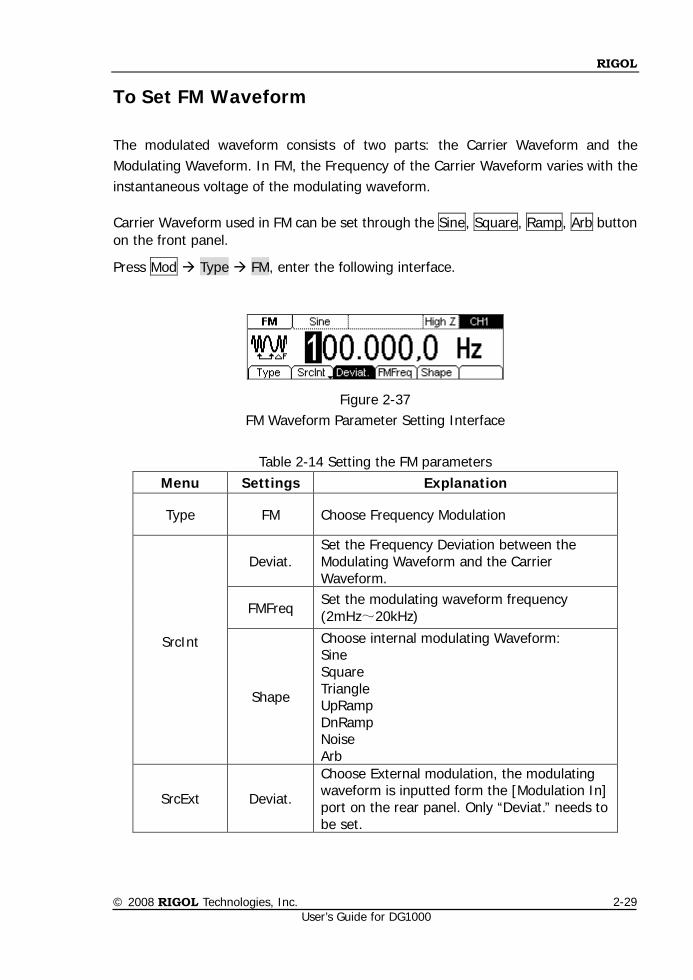
Press Mod Type FM, enter the following interface.
Figure 2-37 FM Waveform Parameter Setting Interface
Table 2-14 Setting the FM parameters
Menu Settings Explanation
Type FM Choose Frequency Modulation
SrcInt
Deviat. Set the Frequency Deviation between the Modulating Waveform and the Carrier Waveform.
FMFreq Set the modulating waveform frequency (2mHz~20kHz)
Shape
Choose internal modulating Waveform: Sine Square Triangle UpRamp DnRamp Noise Arb
SrcExt Deviat.
Choose External modulation, the modulating waveform is inputted form the [Modulation In] port on the rear panel. Only “Deviat.” needs to be set.
RIGOL
© 2008 RIGOL Technologies, Inc. User’s Guide for DG1000
2-30
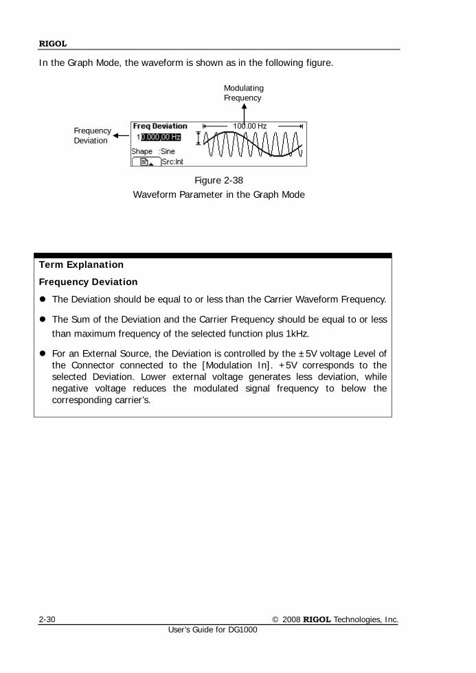
In the Graph Mode, the waveform is shown as in the following figure.
Figure 2-38 Waveform Parameter in the Graph Mode
Term Explanation
Frequency Deviation
The Deviation should be equal to or less than the Carrier Waveform Frequency.
The Sum of the Deviation and the Carrier Frequency should be equal to or less than maximum frequency of the selected function plus 1kHz.
For an External Source, the Deviation is controlled by the ±5V voltage Level of the Connector connected to the [Modulation In]. +5V corresponds to the selected Deviation. Lower external voltage generates less deviation, while negative voltage reduces the modulated signal frequency to below the corresponding carrier’s.
Modulating Frequency
Frequency Deviation
RIGOL
© 2008 RIGOL Technologies, Inc. User’s Guide for DG1000
2-31
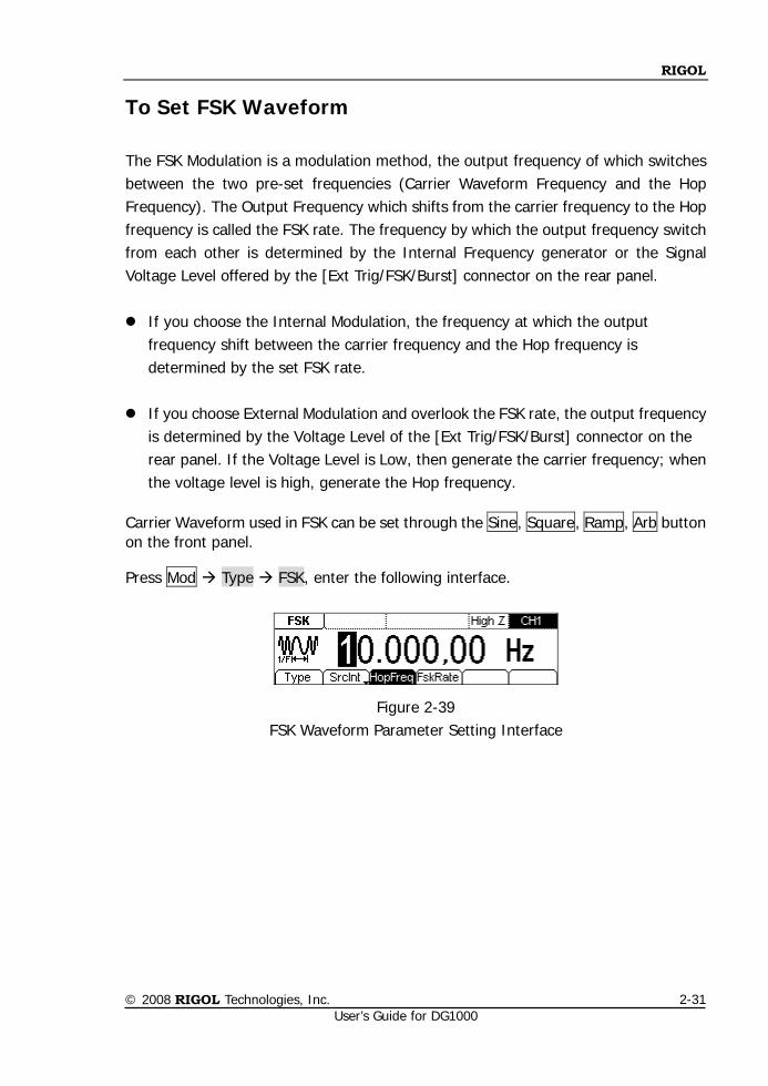
To Set FSK Waveform
The FSK Modulation is a modulation method, the output frequency of which switches between the two pre-set frequencies (Carrier Waveform Frequency and the Hop Frequency). The Output Frequency which shifts from the carrier frequency to the Hop frequency is called the FSK rate. The frequency by which the output frequency switch from each other is determined by the Internal Frequency generator or the Signal Voltage Level offered by the [Ext Trig/FSK/Burst] connector on the rear panel. If you choose the Internal Modulation, the frequency at which the output
frequency shift between the carrier frequency and the Hop frequency is determined by the set FSK rate.
If you choose External Modulation and overlook the FSK rate, the output frequency
is determined by the Voltage Level of the [Ext Trig/FSK/Burst] connector on the rear panel. If the Voltage Level is Low, then generate the carrier frequency; when the voltage level is high, generate the Hop frequency.
Carrier Waveform used in FSK can be set through the Sine, Square, Ramp, Arb button on the front panel.
Press Mod Type FSK, enter the following interface.
Figure 2-39 FSK Waveform Parameter Setting Interface
RIGOL
© 2008 RIGOL Technologies, Inc. User’s Guide for DG1000
2-32
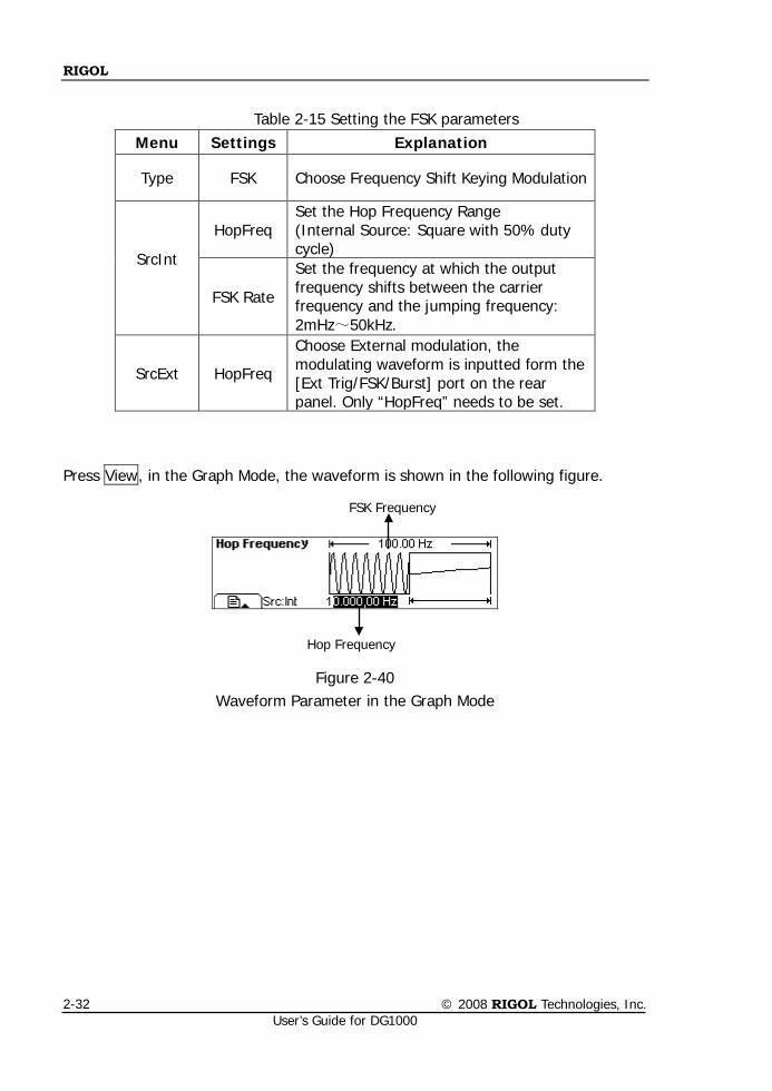
Table 2-15 Setting the FSK parameters
Menu Settings Explanation
Type FSK Choose Frequency Shift Keying Modulation
SrcInt
HopFreq Set the Hop Frequency Range (Internal Source: Square with 50% duty cycle)
FSK Rate
Set the frequency at which the output frequency shifts between the carrier frequency and the jumping frequency: 2mHz~50kHz.
SrcExt HopFreq
Choose External modulation, the modulating waveform is inputted form the [Ext Trig/FSK/Burst] port on the rear panel. Only “HopFreq” needs to be set.
Press View, in the Graph Mode, the waveform is shown in the following figure.
Figure 2-40 Waveform Parameter in the Graph Mode
FSK Frequency
Hop Frequency
RIGOL
© 2008 RIGOL Technologies, Inc. User’s Guide for DG1000
2-33
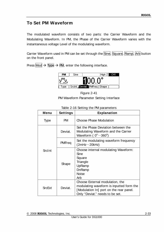
To Set PM Waveform
The modulated waveform consists of two parts: the Carrier Waveform and the Modulating Waveform. In PM, the Phase of the Carrier Waveform varies with the instantaneous voltage Level of the modulating waveform. Carrier Waveform used in PM can be set through the Sine, Square, Ramp, Arb button on the front panel.
Press Mod Type PM, enter the following interface.
Figure 2-41 PM Waveform Parameter Setting Interface
Table 2-16 Setting the PM parameters
Menu Settings Explanation
Type PM Choose Phase Modulation
SrcInt
Deviat. Set the Phase Deviation between the Modulating Waveform and the Carrier Waveform ( 0o~360o)
PMFreq Set the modulating waveform frequency (2mHz~20kHz)
Shape
Choose internal modulating Waveform: Sine Square Triangle UpRamp DnRamp Noise Arb
SrcExt Deviat.
Choose External modulation, the modulating waveform is inputted form the [Modulation In] port on the rear panel. Only “Deviat.” needs to be set.
RIGOL
© 2008 RIGOL Technologies, Inc. User’s Guide for DG1000
2-34
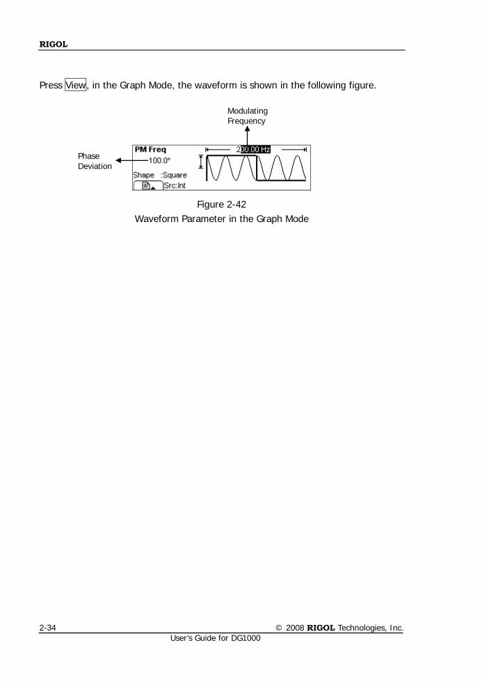
Press View, in the Graph Mode, the waveform is shown in the following figure.
Figure 2-42 Waveform Parameter in the Graph Mode
Modulating Frequency
Phase Deviation
RIGOL
© 2008 RIGOL Technologies, Inc. User’s Guide for DG1000
2-35
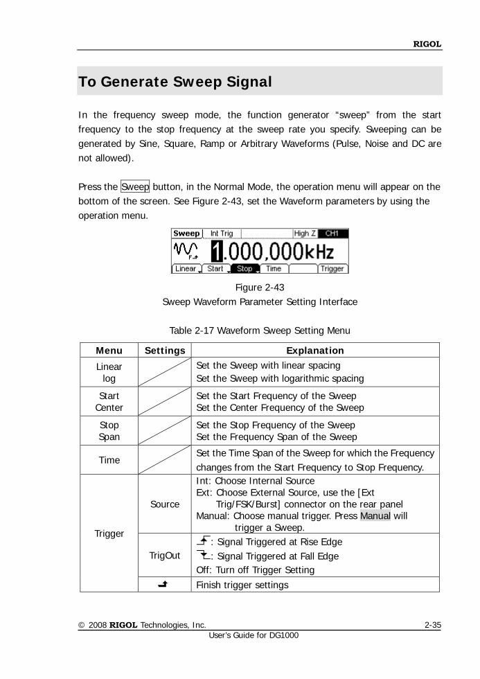
To Generate Sweep Signal
In the frequency sweep mode, the function generator “sweep” from the start frequency to the stop frequency at the sweep rate you specify. Sweeping can be generated by Sine, Square, Ramp or Arbitrary Waveforms (Pulse, Noise and DC are not allowed). Press the Sweep button, in the Normal Mode, the operation menu will appear on the bottom of the screen. See Figure 2-43, set the Waveform parameters by using the operation menu.
Figure 2-43 Sweep Waveform Parameter Setting Interface
Table 2-17 Waveform Sweep Setting Menu
Menu Settings Explanation
Linear log
Set the Sweep with linear spacing Set the Sweep with logarithmic spacing
Start Center Set the Start Frequency of the Sweep
Set the Center Frequency of the Sweep
Stop Span Set the Stop Frequency of the Sweep
Set the Frequency Span of the Sweep
Time Set the Time Span of the Sweep for which the Frequency changes from the Start Frequency to Stop Frequency.
Trigger
Source
Int: Choose Internal Source Ext: Choose External Source, use the [Ext
Trig/FSK/Burst] connector on the rear panel Manual: Choose manual trigger. Press Manual will
trigger a Sweep.
TrigOut : Signal Triggered at Rise Edge : Signal Triggered at Fall Edge
Off: Turn off Trigger Setting
Finish trigger settings
RIGOL
© 2008 RIGOL Technologies, Inc. User’s Guide for DG1000
2-36
Sweep Frequency Setting Use Start and Stop or Center and Span to set the range of the frequency. Press the button again to switch to each other. To Sweep upward, set the Start Frequency lower than the Stop Frequency, or set a
positive frequency interval. To Sweep downward, set the Start Frequency higher than the Stop Frequency, or
set a negative frequency interval.
Instructions
Possible changes or varies to the amplitude characteristic of output signal may happen while sweep frequency on a large scale.
RIGOL
© 2008 RIGOL Technologies, Inc. User’s Guide for DG1000
2-37
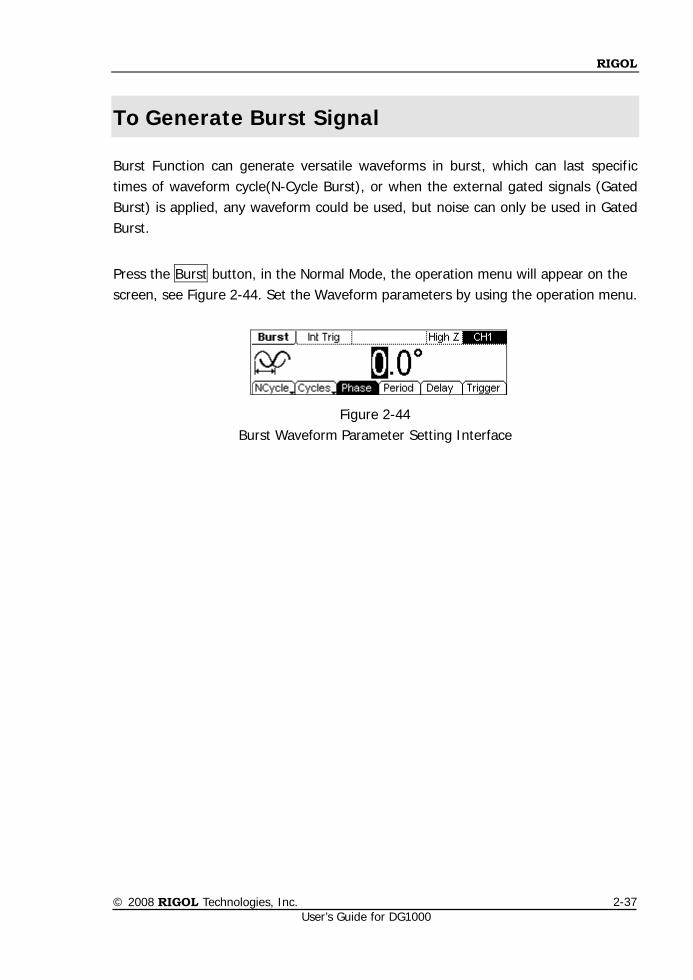
To Generate Burst Signal
Burst Function can generate versatile waveforms in burst, which can last specific times of waveform cycle(N-Cycle Burst), or when the external gated signals (Gated Burst) is applied, any waveform could be used, but noise can only be used in Gated Burst.
Press the Burst button, in the Normal Mode, the operation menu will appear on the screen, see Figure 2-44. Set the Waveform parameters by using the operation menu.
Figure 2-44 Burst Waveform Parameter Setting Interface
RIGOL
© 2008 RIGOL Technologies, Inc. User’s Guide for DG1000
2-38
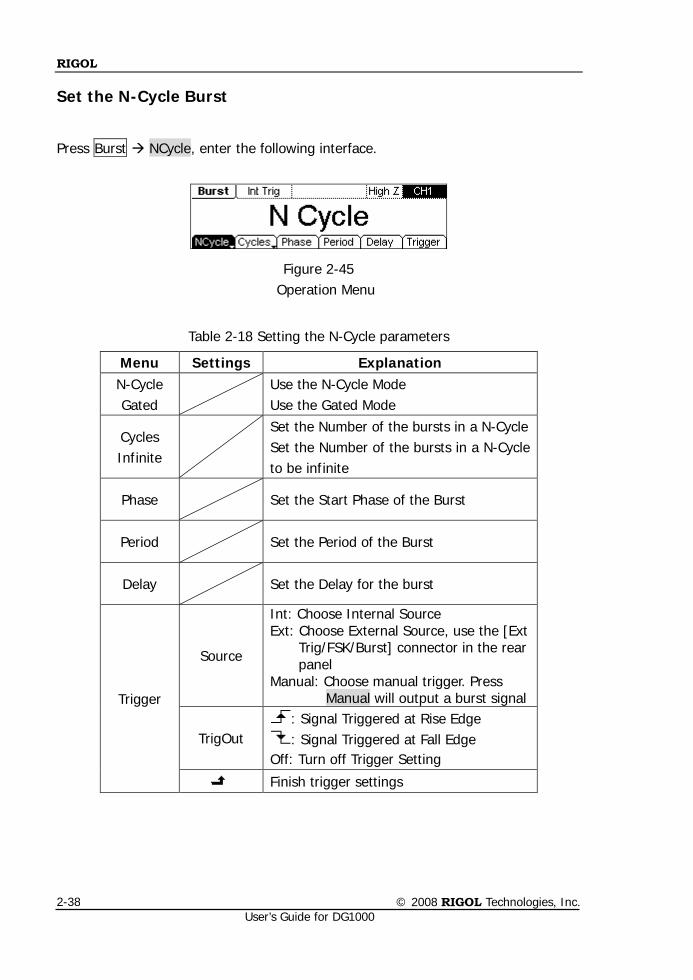
Set the N-Cycle Burst
Press Burst NCycle, enter the following interface.
Figure 2-45 Operation Menu
Table 2-18 Setting the N-Cycle parameters
Menu Settings Explanation N-Cycle Gated
Use the N-Cycle Mode Use the Gated Mode
Cycles Infinite
Set the Number of the bursts in a N-Cycle Set the Number of the bursts in a N-Cycle to be infinite
Phase Set the Start Phase of the Burst
Period Set the Period of the Burst
Delay Set the Delay for the burst
Trigger
Source
Int: Choose Internal Source Ext: Choose External Source, use the [Ext
Trig/FSK/Burst] connector in the rear panel
Manual: Choose manual trigger. Press Manual will output a burst signal
TrigOut : Signal Triggered at Rise Edge : Signal Triggered at Fall Edge
Off: Turn off Trigger Setting
Finish trigger settings
RIGOL
© 2008 RIGOL Technologies, Inc. User’s Guide for DG1000
2-39
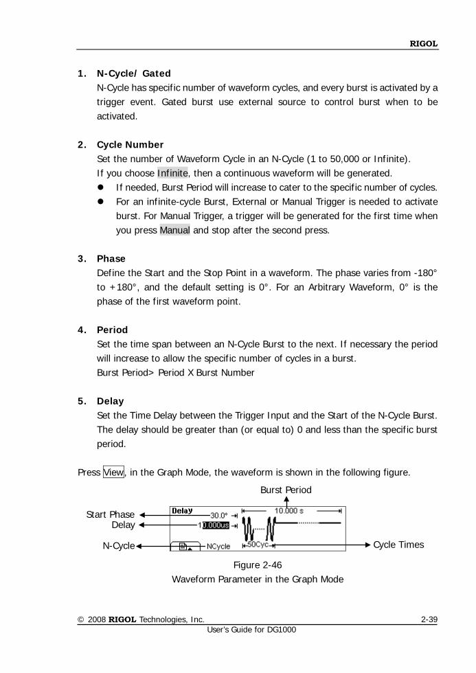
1. N-Cycle/ Gated
N-Cycle has specific number of waveform cycles, and every burst is activated by a trigger event. Gated burst use external source to control burst when to be activated.
2. Cycle Number
Set the number of Waveform Cycle in an N-Cycle (1 to 50,000 or Infinite). If you choose Infinite, then a continuous waveform will be generated. If needed, Burst Period will increase to cater to the specific number of cycles. For an infinite-cycle Burst, External or Manual Trigger is needed to activate
burst. For Manual Trigger, a trigger will be generated for the first time when you press Manual and stop after the second press.
3. Phase
Define the Start and the Stop Point in a waveform. The phase varies from -180° to +180°, and the default setting is 0°. For an Arbitrary Waveform, 0° is the phase of the first waveform point.
4. Period
Set the time span between an N-Cycle Burst to the next. If necessary the period will increase to allow the specific number of cycles in a burst. Burst Period> Period X Burst Number
5. Delay
Set the Time Delay between the Trigger Input and the Start of the N-Cycle Burst. The delay should be greater than (or equal to) 0 and less than the specific burst period.
Press View, in the Graph Mode, the waveform is shown in the following figure.
Figure 2-46 Waveform Parameter in the Graph Mode
Start Phase
Burst Period
Cycle Times
Delay
N-Cycle
RIGOL
© 2008 RIGOL Technologies, Inc. User’s Guide for DG1000
2-40
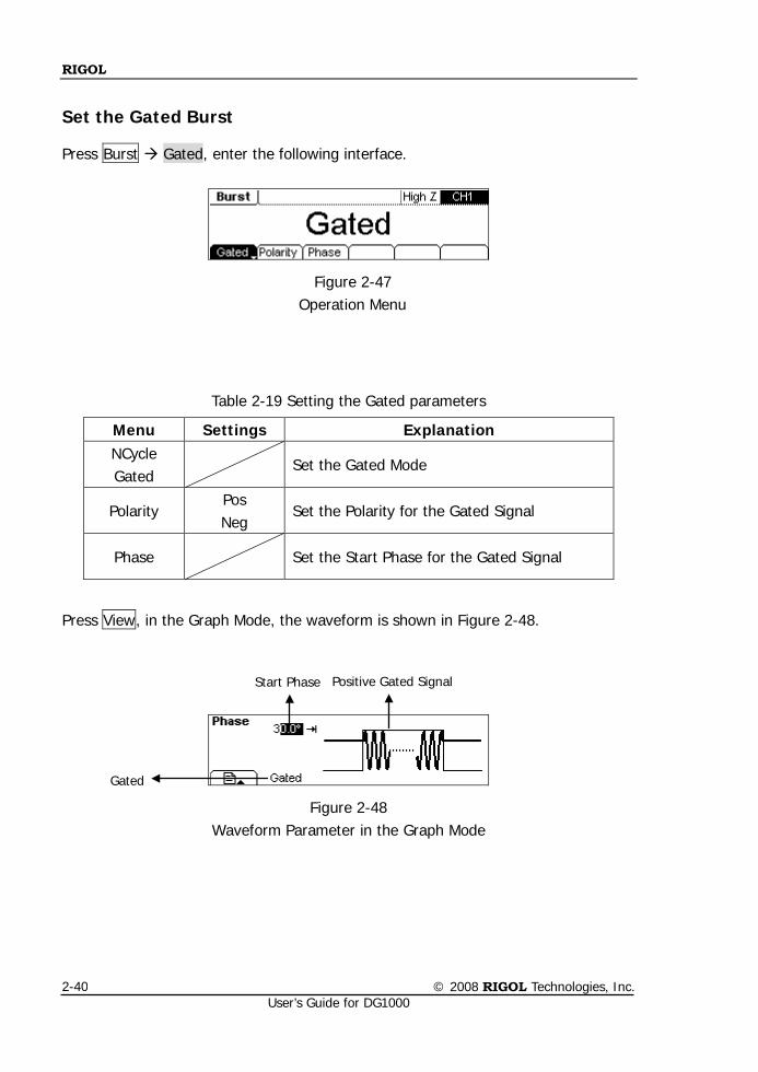
Set the Gated Burst
Press Burst Gated, enter the following interface.
Figure 2-47 Operation Menu
Table 2-19 Setting the Gated parameters
Menu Settings Explanation NCycle Gated
Set the Gated Mode
Polarity Pos Neg
Set the Polarity for the Gated Signal
Phase Set the Start Phase for the Gated Signal
Press View, in the Graph Mode, the waveform is shown in Figure 2-48.
Figure 2-48 Waveform Parameter in the Graph Mode
Positive Gated Signal
Gated
Start Phase
RIGOL
© 2008 RIGOL Technologies, Inc. User’s Guide for DG1000
2-41
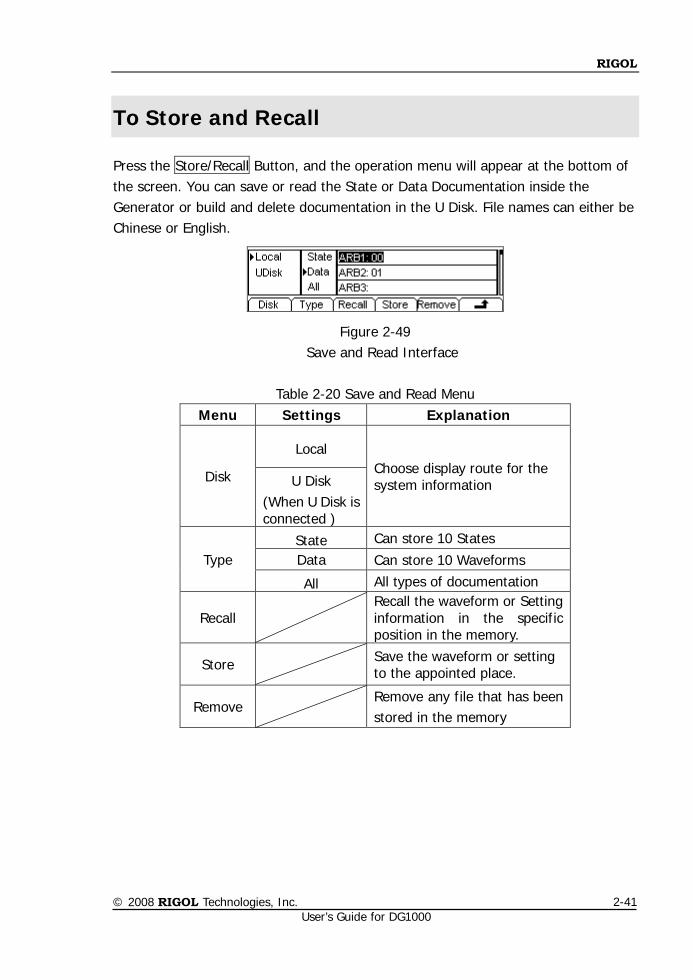
To Store and Recall
Press the Store/Recall Button, and the operation menu will appear at the bottom of the screen. You can save or read the State or Data Documentation inside the Generator or build and delete documentation in the U Disk. File names can either be Chinese or English.
Figure 2-49 Save and Read Interface
Table 2-20 Save and Read Menu
Menu Settings Explanation
Disk
Local Choose display route for the system information U Disk
(When U Disk is connected )
Type State Can store 10 States Data Can store 10 Waveforms
All All types of documentation
Recall Recall the waveform or Setting information in the specific position in the memory.
Store
Save the waveform or setting to the appointed place.
Remove Remove any file that has been stored in the memory
RIGOL
© 2008 RIGOL Technologies, Inc. User’s Guide for DG1000
2-42
To Save the Instrument State
Users are allowed to store the instrument state on any of the 10 Non-Volatile Memories. The state storage will “memorize” the selected function (including the Arbitrary Waveform), Frequency, Amplitude, DC Offset, Phase, Duty Cycle, Symmetry, and other modulation parameter used. To Save the Instrument State, following the steps: (1) Choose the file Type to store
Press Store/Recall State, and choose the storage type to be “State”.
(2) Choose the location of the file. There are ten positions in the Local STATE1, STATE2……STATE10, choose one of them by rotating the knob.
(3) Name the file and Save it Press Store button, enter the desired name. Press Store to finish.
RIGOL
© 2008 RIGOL Technologies, Inc. User’s Guide for DG1000
2-43
To Save Data
Users are allowed to store data document in any of the 10 Non-Volatile Memories. If the place is already occupied, the new document will cover the old one. To save the data, following the steps: (1) Choose the file Type to store
Press Store/Recall data, and choose “data” as the storage type.
(2) Choose the location of the file. There are ten positions in the Local ARB1, ARB2……ARB10, choose one of them by rotating the knob.
(3) Name the file and Save Press Store button, enter the desired name. Press Store to finish.
RIGOL
© 2008 RIGOL Technologies, Inc. User’s Guide for DG1000
2-44
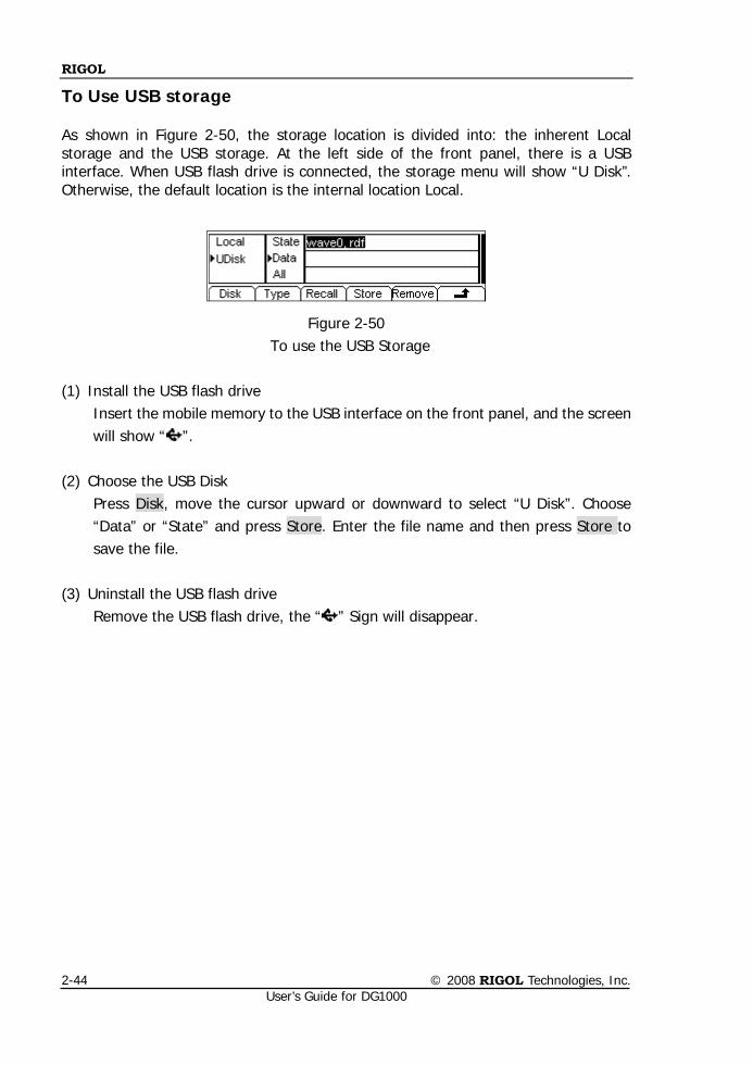
To Use USB storage As shown in Figure 2-50, the storage location is divided into: the inherent Local storage and the USB storage. At the left side of the front panel, there is a USB interface. When USB flash drive is connected, the storage menu will show “U Disk”. Otherwise, the default location is the internal location Local.
Figure 2-50 To use the USB Storage
(1) Install the USB flash drive
Insert the mobile memory to the USB interface on the front panel, and the screen will show “ ”.
(2) Choose the USB Disk Press Disk, move the cursor upward or downward to select “U Disk”. Choose “Data” or “State” and press Store. Enter the file name and then press Store to save the file.
(3) Uninstall the USB flash drive Remove the USB flash drive, the “ ” Sign will disappear.
RIGOL
© 2008 RIGOL Technologies, Inc. User’s Guide for DG1000
2-45
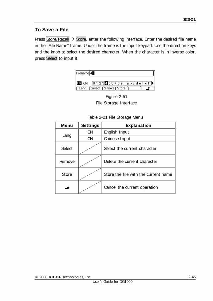
To Save a File
Press Store/Recall Store, enter the following interface. Enter the desired file name in the “File Name” frame. Under the frame is the input keypad. Use the direction keys and the knob to select the desired character. When the character is in inverse color, press Select to input it.
Figure 2-51 File Storage Interface
Table 2-21 File Storage Menu
Menu Settings Explanation
Lang EN English Input CN Chinese Input
Select Select the current character
Remove Delete the current character
Store Store the file with the current name
Cancel the current operation
RIGOL
© 2008 RIGOL Technologies, Inc. User’s Guide for DG1000
2-46
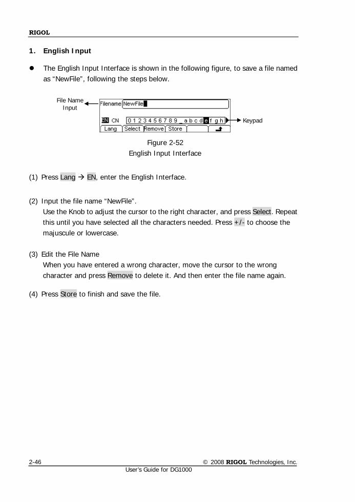
1. English Input
The English Input Interface is shown in the following figure, to save a file named as “NewFile”, following the steps below.
Figure 2-52 English Input Interface
(1) Press Lang EN, enter the English Interface.
(2) Input the file name “NewFile”. Use the Knob to adjust the cursor to the right character, and press Select. Repeat this until you have selected all the characters needed. Press +/- to choose the majuscule or lowercase.
(3) Edit the File Name When you have entered a wrong character, move the cursor to the wrong character and press Remove to delete it. And then enter the file name again.
(4) Press Store to finish and save the file.
File Name Input
Keypad
RIGOL
© 2008 RIGOL Technologies, Inc. User’s Guide for DG1000
2-47
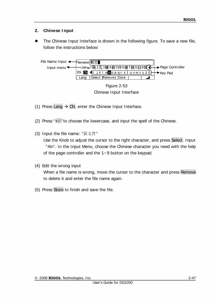
2. Chinese Input
The Chinese Input Interface is shown in the following figure. To save a new file, follow the instructions below:
Figure 2-53 Chinese Input Interface
(1) Press Lang CN, enter the Chinese Input Interface.
(2) Press “+/-”to choose the lowercase, and input the spell of the Chinese.
(3) Input the file name: “新文件” Use the Knob to adjust the cursor to the right character, and press Select. Input “Xin”. In the Input Menu, choose the Chinese character you need with the help of the page controller and the 1~9 button on the keypad.
(4) Edit the wrong input When a file name is wrong, move the cursor to the character and press Remove to delete it and enter the file name again.
(5) Press Store to finish and save the file.
Key Pad Input menu
File Name Input Page Controller
RIGOL
© 2008 RIGOL Technologies, Inc. User’s Guide for DG1000
2-48
To Set the Utility Function
With the Utility Function, you can set the Sync On/Off, Channel Output Parameters, Channel Coupling, Channel Copy, Counter Measurement, Interface Parameter, System Setting and Test/Cal Parameter. Sync switch offers the option to choose the Sync Signal or not. The Channel Output parameters provide the parameter setting for
Load/Impedance, Normal/ Invert. Channel Coupling provides Frequency/Phase coupling of the two channels. Channel Copy provides parameter copy of the two channels. Counter provides Frequency measurement function. The Interface Parameter offers USB serial-number viewing. The System Setting provides the setting for Language, Display, Beep, Screen
Guard, Format, Power System Configure, Default and Timer setting. The Test/Cal Parameter provides the self-testing and calibration storage as well as
the password and safety switch.
RIGOL
© 2008 RIGOL Technologies, Inc. User’s Guide for DG1000
2-49
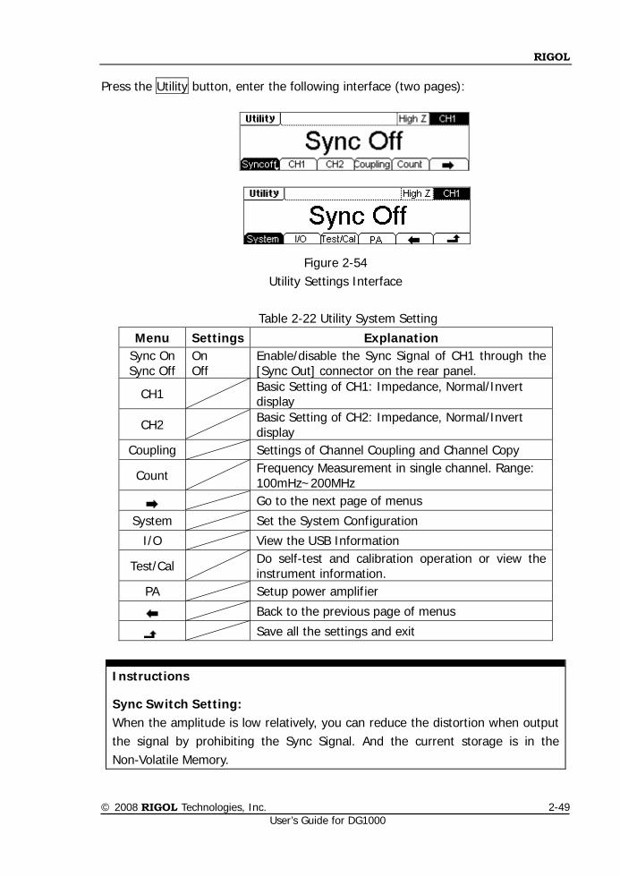
Press the Utility button, enter the following interface (two pages):
Figure 2-54 Utility Settings Interface
Table 2-22 Utility System Setting
Menu Settings Explanation Sync On Sync Off
On Off
Enable/disable the Sync Signal of CH1 through the [Sync Out] connector on the rear panel.
CH1 Basic Setting of CH1: Impedance, Normal/Invert display
CH2 Basic Setting of CH2: Impedance, Normal/Invert display
Coupling Settings of Channel Coupling and Channel Copy
Count Frequency Measurement in single channel. Range: 100mHz~200MHz
Go to the next page of menus
System Set the System Configuration
I/O View the USB Information
Test/Cal Do self-test and calibration operation or view the instrument information.
PA Setup power amplifier
Back to the previous page of menus
Save all the settings and exit
Instructions
Sync Switch Setting: When the amplitude is low relatively, you can reduce the distortion when output the signal by prohibiting the Sync Signal. And the current storage is in the Non-Volatile Memory.
RIGOL
© 2008 RIGOL Technologies, Inc. User’s Guide for DG1000
2-50
To Set the Sync Output
The Generator provides Sync signal output of CH1 through the [Sync Out] Connector on the Rear Panel. All the standard output functions (except DC and Noise) have a corresponding Sync Signal. For some Sync applications, they can be prohibited if users do not want to use them. In the default setting, the Sync Signal output is disabled. The output Voltage of
the [Sync Out] Connector Level is Low.
In the Invert mode, the waveform that corresponds to the Sync signal does not Inverse.
If frequency of the standard output function (except DC and Noise) is higher than
2MHz, the Sync output will automatically turn off. For Sine, Square, Ramp and Pulse Signal, the Sync Signal is a Square Signal with
50% Duty Cycle. When the output is positive, The Sync Signal is TTL Level High compared to 0 V Voltage or DC Offset; when the output is negative, The Sync Signal is TTL Level Low compared to 0 V Voltage or DC Offset.
For Arbitrary Waveform, the Sync Signal is a Square Waveform with 50% Duty
Cycle. At the time when the first output waveform point is generated, the Sync Signal Voltage is TTL Level High.
For the internal Modulating of AM, FM and PM, the Sync Signal reference is the
Modulated Signal (not the Carrier Signal). The Sync Signal is a Square Waveform with 50% Duty Cycle. In the first half modulation period, the Sync Signal is TTL Level High. For External Modulation, the Sync Signal reference is the Carrier Signal (not the Modulated Signal). The Sync Signal is also a Square Waveform with 50% Duty Cycle.
For FSK, the Sync Signal Reference is the Hop Frequency, and the Sync Signal is a
Square Waveform with 50% Duty Cycle. For the Hop Frequency, at the hopping point, the Sync Signal is TTL Level High.
For the Burst, when the burst starts, the Sync Signal is Level High. At the specific
point when the Cycle Number ends, the Sync Signal turns Level Low (If the
RIGOL
© 2008 RIGOL Technologies, Inc. User’s Guide for DG1000
2-51
Waveform has a relative starting phase, it may be not intersection). For an infinite burst, the Sync Signal is the same as the Sync Signal of the continuous Signal.
For the External Gated Burst, the Sync Signal follows the External Gated Signal.
But, please note that this signal will not turn Level Low until the last period end (If the Waveform has a relative starting phase, it may be not intersection).
RIGOL
© 2008 RIGOL Technologies, Inc. User’s Guide for DG1000
2-52
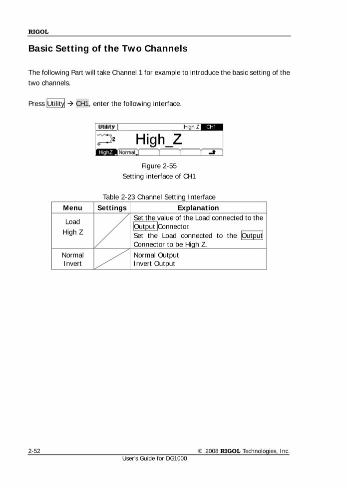
Basic Setting of the Two Channels
The following Part will take Channel 1 for example to introduce the basic setting of the two channels. Press Utility CH1, enter the following interface.
Figure 2-55 Setting interface of CH1
Table 2-23 Channel Setting Interface
Menu Settings Explanation
Load High Z
Set the value of the Load connected to the Output Connector. Set the Load connected to the Output Connector to be High Z.
Normal Invert Normal Output
Invert Output
RIGOL
© 2008 RIGOL Technologies, Inc. User’s Guide for DG1000
2-53
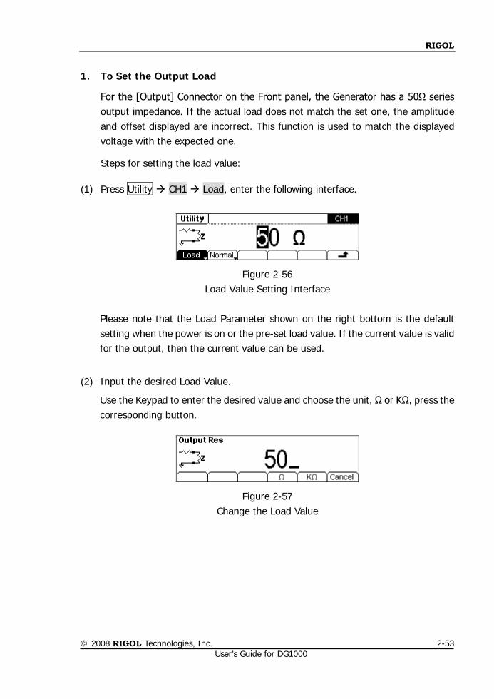
1. To Set the Output Load
For the [Output] Connector on the Front panel, the Generator has a 50Ω series output impedance. If the actual load does not match the set one, the amplitude and offset displayed are incorrect. This function is used to match the displayed voltage with the expected one.
Steps for setting the load value:
(1) Press Utility CH1 Load, enter the following interface.
Figure 2-56 Load Value Setting Interface
Please note that the Load Parameter shown on the right bottom is the default setting when the power is on or the pre-set load value. If the current value is valid for the output, then the current value can be used.
(2) Input the desired Load Value.
Use the Keypad to enter the desired value and choose the unit, Ω or KΩ, press the corresponding button.
Figure 2-57 Change the Load Value
RIGOL
© 2008 RIGOL Technologies, Inc. User’s Guide for DG1000
2-54
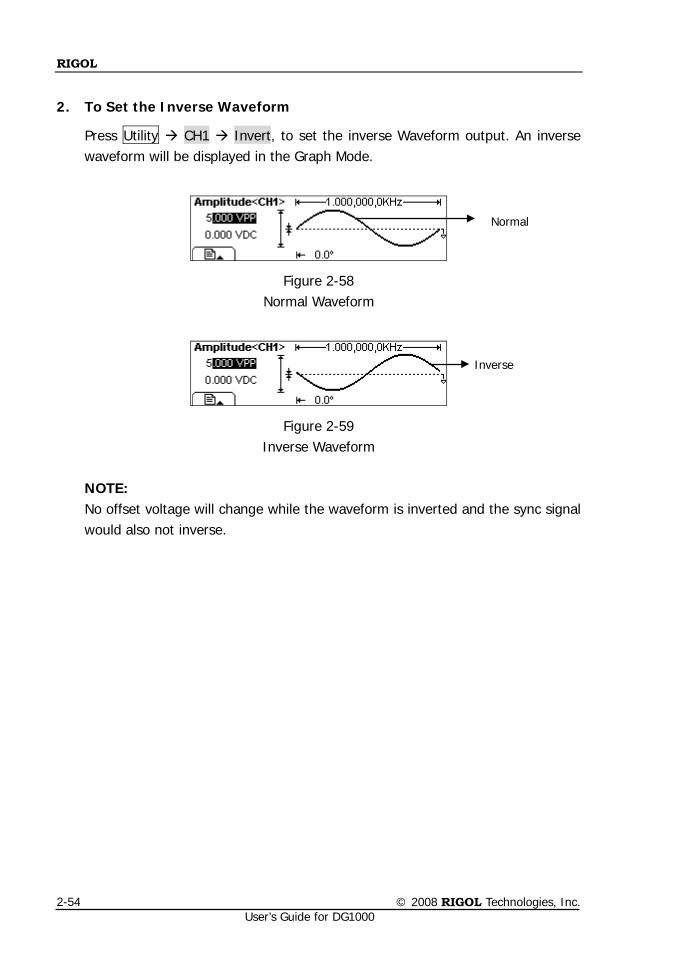
2. To Set the Inverse Waveform
Press Utility CH1 Invert, to set the inverse Waveform output. An inverse waveform will be displayed in the Graph Mode.
Figure 2-58 Normal Waveform
Figure 2-59 Inverse Waveform
NOTE: No offset voltage will change while the waveform is inverted and the sync signal would also not inverse.
Normal
Inverse
RIGOL
© 2008 RIGOL Technologies, Inc. User’s Guide for DG1000
2-55
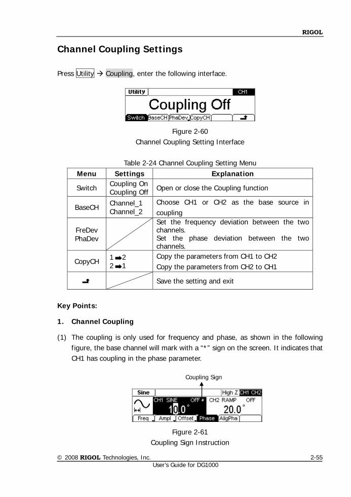
Channel Coupling Settings
Press Utility Coupling, enter the following interface.
Figure 2-60 Channel Coupling Setting Interface
Table 2-24 Channel Coupling Setting Menu
Menu Settings Explanation
Switch Coupling On Coupling Off Open or close the Coupling function
BaseCH Channel_1 Channel_2
Choose CH1 or CH2 as the base source in coupling
FreDev PhaDev
Set the frequency deviation between the two channels. Set the phase deviation between the two channels.
CopyCH 1 2 2 1
Copy the parameters from CH1 to CH2 Copy the parameters from CH2 to CH1
Save the setting and exit
Key Points:
1. Channel Coupling
(1) The coupling is only used for frequency and phase, as shown in the following figure, the base channel will mark with a “*” sign on the screen. It indicates that CH1 has coupling in the phase parameter.
Figure 2-61 Coupling Sign Instruction
Coupling Sign
RIGOL
© 2008 RIGOL Technologies, Inc. User’s Guide for DG1000
2-56
(2) Only frequency or phase can be coupled each time, it depends on the current
selection is FreDev or PhaDev. 2. Channel Copy
(1) Only when the coupling is closed, the Copy menu would appear.
(2) Only parameters will be copied in the channel copy operation.
(3) Channel copy is limited by parameters inspection.
Frequency limitation Different waveforms have different upper/lower limits of the frequency. When waveforms in the two channels are different, the highest frequency can be copied depends on the waveform which has lower frequency. For instance, a Sine waveform of 5MHz can not be copy to a Ramp (frequency upper limit is 150 KHz).
limitation of the Amplitude and Output impedance setting The upper/lower limits of Amplitude are different in different channels and modes. Before copying, the Output impedance setting of the two channels should be the same. Take CH1 for example, to set the Output impedance, press Utility CH1 Load/High Z, then set the value in need.
Channel inverting limitation If a channel has been set to Invert, after the copying, the two channels will still have 180° phase deviation though the “Phase” parameter has been copied.
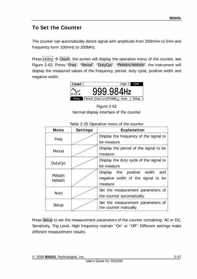
RIGOL
© 2008 RIGOL Technologies, Inc. User’s Guide for DG1000
2-57
To Set the Counter
The counter can automatically detect signal with amplitude from 200mVPP to 5VPP and frequency form 100mHz to 200MHz. Press Utility Count, the screen will display the operation menu of the counter, see Figure 2-62. Press “Freq”, “Period”, “DutyCyc”, “PWidth/NWidth”, the instrument will display the measured values of the frequency, period, duty cycle, positive width and negative width.
Figure 2-62 Normal display interface of the counter
Table 2-25 Operation menu of the counter
Menu Settings Explanation
Freq Display the frequency of the signal to be measure
Period Display the period of the signal to be measure
DutyCyc
Display the duty cycle of the signal to be measure
PWidth NWidth
Display the positive width and negative width of the signal to be measure
Auto Set the measurement parameters of the counter automatically.
Setup Set the measurement parameters of the counter manually.
Press Setup to set the measurement parameters of the counter containing: AC or DC, Sensitivity, Trig Level, High frequency restrain “On” or “Off”. Different settings make different measurement results.
RIGOL
© 2008 RIGOL Technologies, Inc. User’s Guide for DG1000
2-58
Instructions
The data shown on the screen will be refurbished periodically if input frequency signal from external, or which will be stopped refurbishing as soon as you cut off input and last frequency value will be displayed.
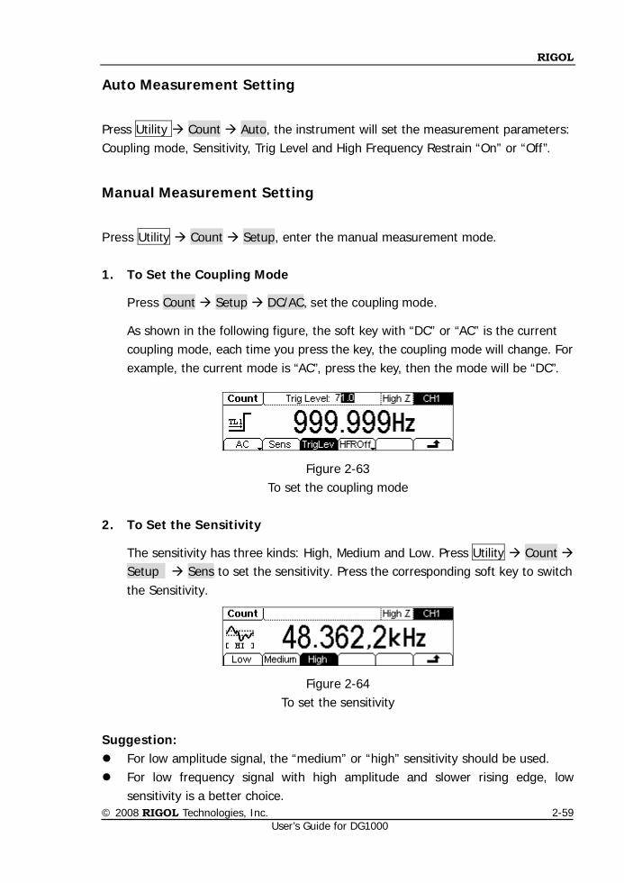
RIGOL
© 2008 RIGOL Technologies, Inc. User’s Guide for DG1000
2-59
Auto Measurement Setting
Press Utility Count Auto, the instrument will set the measurement parameters: Coupling mode, Sensitivity, Trig Level and High Frequency Restrain “On” or “Off”.
Manual Measurement Setting
Press Utility Count Setup, enter the manual measurement mode. 1. To Set the Coupling Mode
Press Count Setup DC/AC, set the coupling mode.
As shown in the following figure, the soft key with “DC” or “AC” is the current coupling mode, each time you press the key, the coupling mode will change. For example, the current mode is “AC”, press the key, then the mode will be “DC”.
Figure 2-63 To set the coupling mode
2. To Set the Sensitivity
The sensitivity has three kinds: High, Medium and Low. Press Utility Count Setup Sens to set the sensitivity. Press the corresponding soft key to switch the Sensitivity.
Figure 2-64 To set the sensitivity
Suggestion: For low amplitude signal, the “medium” or “high” sensitivity should be used. For low frequency signal with high amplitude and slower rising edge, low
sensitivity is a better choice.
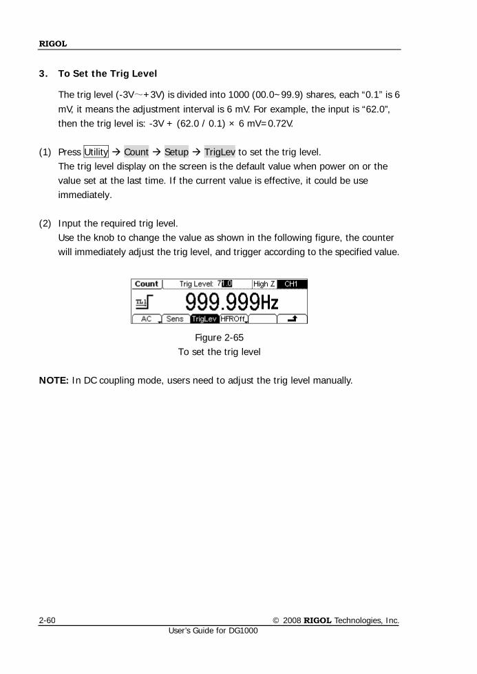
RIGOL
© 2008 RIGOL Technologies, Inc. User’s Guide for DG1000
2-60
3. To Set the Trig Level
The trig level (-3V~+3V) is divided into 1000 (00.0~99.9) shares, each “0.1” is 6 mV, it means the adjustment interval is 6 mV. For example, the input is “62.0”, then the trig level is: -3V + (62.0 / 0.1) × 6 mV=0.72V.
(1) Press Utility Count Setup TrigLev to set the trig level.
The trig level display on the screen is the default value when power on or the value set at the last time. If the current value is effective, it could be use immediately.
(2) Input the required trig level.
Use the knob to change the value as shown in the following figure, the counter will immediately adjust the trig level, and trigger according to the specified value.
Figure 2-65 To set the trig level
NOTE: In DC coupling mode, users need to adjust the trig level manually.
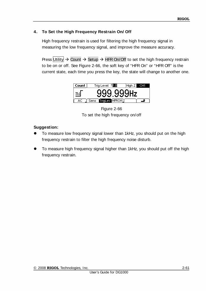
RIGOL
© 2008 RIGOL Technologies, Inc. User’s Guide for DG1000
2-61
4. To Set the High Frequency Restrain On/Off High frequency restrain is used for filtering the high frequency signal in measuring the low frequency signal, and improve the measure accuracy.
Press Utility Count Setup HFR On/Off to set the high frequency restrain to be on or off. See Figure 2-66, the soft key of “HFR On” or “HFR Off” is the current state, each time you press the key, the state will change to another one.
Figure 2-66 To set the high frequency on/off
Suggestion: To measure low frequency signal lower than 1kHz, you should put on the high
frequency restrain to filter the high frequency noise disturb.
To measure high frequency signal higher than 1kHz, you should put off the high frequency restrain.
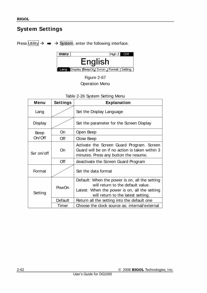
RIGOL
© 2008 RIGOL Technologies, Inc. User’s Guide for DG1000
2-62
System Settings
Press Utility System, enter the following interface.
Figure 2-67 Operation Menu
Table 2-26 System Setting Menu
Menu Settings Explanation
Lang Set the Display Language
Display Set the parameter for the Screen Display
Beep On/Off
On Open Beep Off Close Beep
Svr on/off On
Activate the Screen Guard Program. Screen Guard will be on if no action is taken within 3 minutes. Press any button the resume.
Off deactivate the Screen Guard Program
Format Set the data format
Setting PowOn
Default: When the power is on, all the setting will return to the default value.
Latest: When the power is on, all the setting will return to the latest setting.
Default Return all the setting into the default one Timer Choose the clock source as: internal/external
RIGOL
© 2008 RIGOL Technologies, Inc. User’s Guide for DG1000
2-63
Key points: Power On The Setting is used when the machine is power on. Two choices are available: the default setting and the latest. Once selected, the
setting will be used when the instrument is restarted. Beep Activate or deactivate the sound when an error occurs from the front panel or the
remote interface. Activate or deactivate any sound made by the button or knob on the front panel.
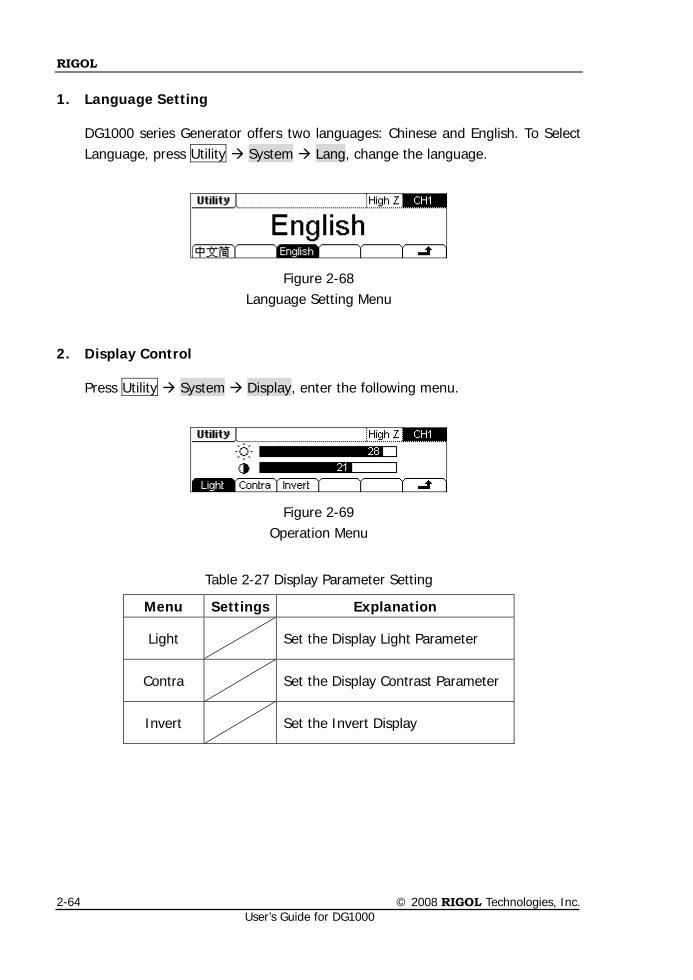
RIGOL
© 2008 RIGOL Technologies, Inc. User’s Guide for DG1000
2-64
1. Language Setting
DG1000 series Generator offers two languages: Chinese and English. To Select Language, press Utility System Lang, change the language.
Figure 2-68 Language Setting Menu
2. Display Control
Press Utility System Display, enter the following menu.
Figure 2-69 Operation Menu
Table 2-27 Display Parameter Setting
Menu Settings Explanation
Light Set the Display Light Parameter
Contra Set the Display Contrast Parameter
Invert Set the Invert Display
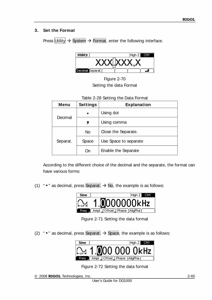
RIGOL
© 2008 RIGOL Technologies, Inc. User’s Guide for DG1000
2-65
3. Set the Format
Press Utility System Format, enter the following interface.
Figure 2-70 Setting the data Format
Table 2-28 Setting the Data Format
Menu Settings Explanation
Decimal Using dot
Using comma
Separat.
No Close the Separate.
Space Use Space to separate
On Enable the Separate
According to the different choice of the decimal and the separate, the format can have various forms:
(1) “ ” as decimal, press Separat. No, the example is as follows:
Figure 2-71 Setting the data format
(2) “ ” as decimal, press Separat. Space, the example is as follows:
Figure 2-72 Setting the data format
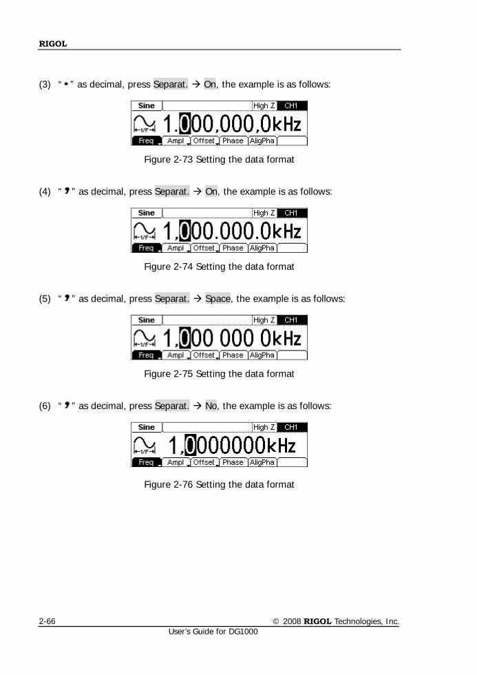
RIGOL
© 2008 RIGOL Technologies, Inc. User’s Guide for DG1000
2-66
(3) “ ” as decimal, press Separat. On, the example is as follows:
Figure 2-73 Setting the data format
(4) “ ” as decimal, press Separat. On, the example is as follows:
Figure 2-74 Setting the data format
(5) “ ” as decimal, press Separat. Space, the example is as follows:
Figure 2-75 Setting the data format
(6) “ ” as decimal, press Separat. No, the example is as follows:
Figure 2-76 Setting the data format
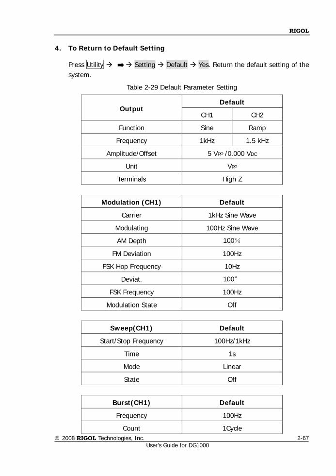
RIGOL
© 2008 RIGOL Technologies, Inc. User’s Guide for DG1000
2-67
4. To Return to Default Setting
Press Utility Setting Default Yes. Return the default setting of the system.
Table 2-29 Default Parameter Setting
Modulation (CH1) Default
Carrier 1kHz Sine Wave
Modulating 100Hz Sine Wave
AM Depth 100%
FM Deviation 100Hz
FSK Hop Frequency 10Hz
Deviat. 100°
FSK Frequency 100Hz
Modulation State Off
Sweep(CH1) Default
Start/Stop Frequency 100Hz/1kHz
Time 1s
Mode Linear
State Off
Burst(CH1) Default
Frequency 100Hz
Count 1Cycle
Output Default
CH1 CH2
Function Sine Ramp
Frequency 1kHz 1.5 kHz
Amplitude/Offset 5 VPP /0.000 VDC
Unit VPP
Terminals High Z
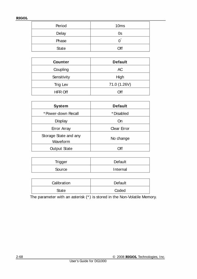
RIGOL
© 2008 RIGOL Technologies, Inc. User’s Guide for DG1000
2-68
Period 10ms
Delay
0s
Phase 0°
State Off
Counter Default
Coupling AC
Sensitivity High
Trig Lev 71.0 (1.26V)
HFR Off Off
System Default
*Power-down Recall *Disabled
Display On
Error Array Clear Error
Storage State and any Waveform
No change
Output State Off
Trigger Default
Source Internal
Calibration Default
State Coded
The parameter with an asterisk (*) is stored in the Non-Volatile Memory.
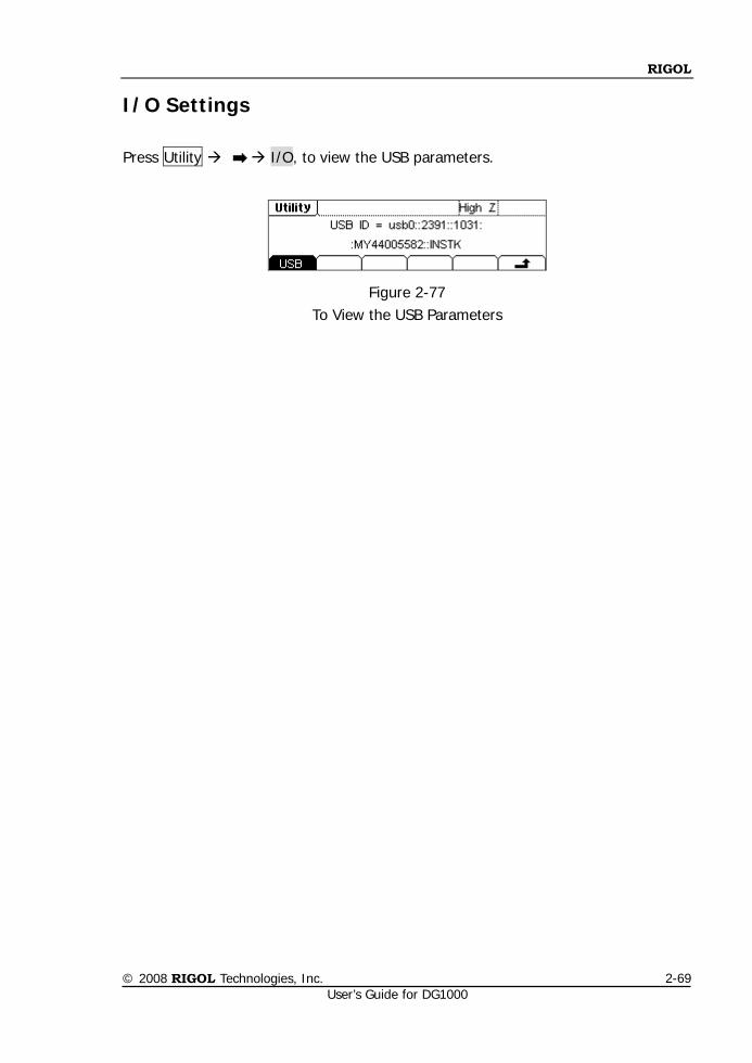
RIGOL
© 2008 RIGOL Technologies, Inc. User’s Guide for DG1000
2-69
I/O Settings
Press Utility I/O, to view the USB parameters.
Figure 2-77 To View the USB Parameters
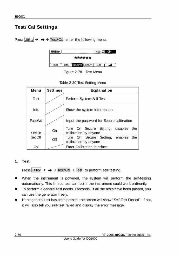
RIGOL
© 2008 RIGOL Technologies, Inc. User’s Guide for DG1000
2-70
Test/Cal Settings
Press Utility Test/Cal, enter the following menu.
Figure 2-78 Test Menu
Table 2-30 Test Setting Menu
1. Test
Press Utility Test/Cal Test, to perform self-testing.
When the instrument is powered, the system will perform the self-testing automatically. This limited test can test if the instrument could work ordinarily.
To perform a general test needs 3 seconds. If all the tests have been passed, you can use the generator freely.
If the general test has been passed, the screen will show “Self-Test Passed”; if not, it will also tell you self-test failed and display the error message.
Menu Settings Explanation
Test Perform System Self-Test
Info Show the system information
PassWd Input the password for Secure calibration
SecOn SecOff
On Turn On Secure Setting, disables the calibration by anyone
Off Turn Off Secure Setting, enables the calibration by anyone
Cal Enter Calibration interface
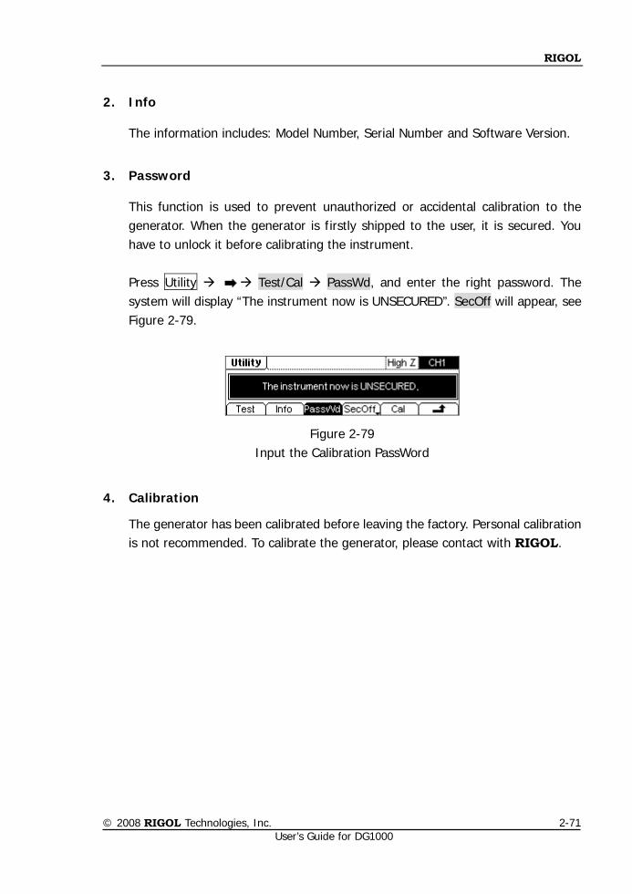
RIGOL
© 2008 RIGOL Technologies, Inc. User’s Guide for DG1000
2-71
2. Info
The information includes: Model Number, Serial Number and Software Version.
3. Password
This function is used to prevent unauthorized or accidental calibration to the generator. When the generator is firstly shipped to the user, it is secured. You have to unlock it before calibrating the instrument.
Press Utility Test/Cal PassWd, and enter the right password. The system will display “The instrument now is UNSECURED”. SecOff will appear, see Figure 2-79.
Figure 2-79 Input the Calibration PassWord
4. Calibration
The generator has been calibrated before leaving the factory. Personal calibration is not recommended. To calibrate the generator, please contact with RIGOL.
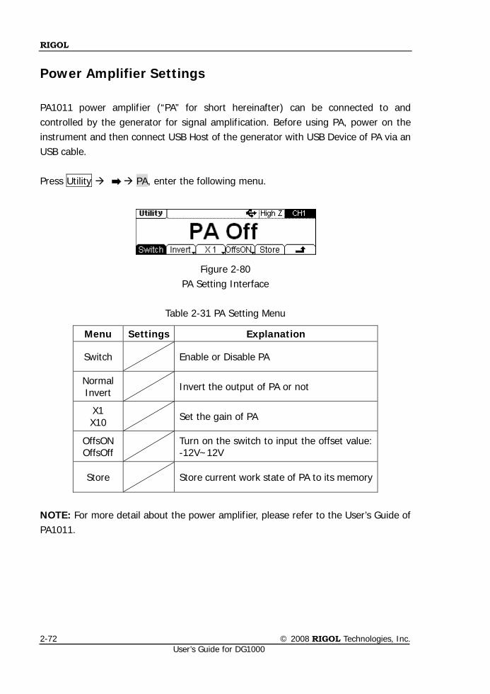
RIGOL
© 2008 RIGOL Technologies, Inc. User’s Guide for DG1000
2-72
Power Amplifier Settings
PA1011 power amplifier (“PA” for short hereinafter) can be connected to and controlled by the generator for signal amplification. Before using PA, power on the instrument and then connect USB Host of the generator with USB Device of PA via an USB cable. Press Utility PA, enter the following menu.
Figure 2-80
PA Setting Interface
Table 2-31 PA Setting Menu
NOTE: For more detail about the power amplifier, please refer to the User’s Guide of PA1011.
Menu Settings Explanation
Switch Enable or Disable PA
Normal Invert Invert the output of PA or not
X1 X10 Set the gain of PA
OffsON OffsOff Turn on the switch to input the offset value:
-12V~12V
Store Store current work state of PA to its memory
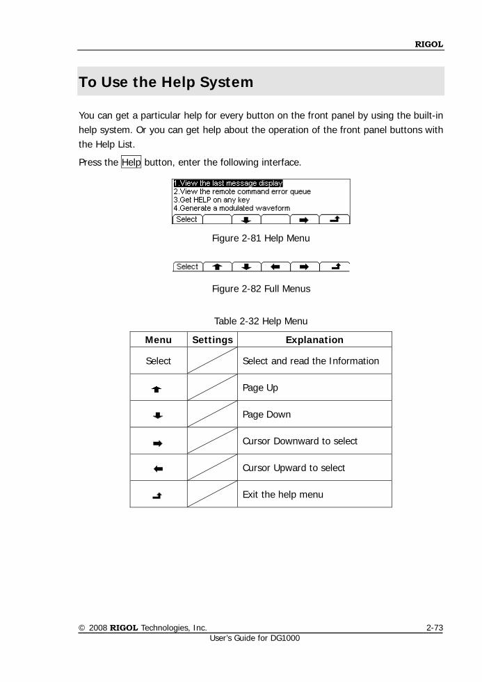
RIGOL
© 2008 RIGOL Technologies, Inc. User’s Guide for DG1000
2-73
To Use the Help System
You can get a particular help for every button on the front panel by using the built-in help system. Or you can get help about the operation of the front panel buttons with the Help List.
Press the Help button, enter the following interface.
Figure 2-81 Help Menu
Figure 2-82 Full Menus
Table 2-32 Help Menu
Menu Settings Explanation
Select Select and read the Information
Page Up
Page Down
Cursor Downward to select
Cursor Upward to select
Exit the help menu
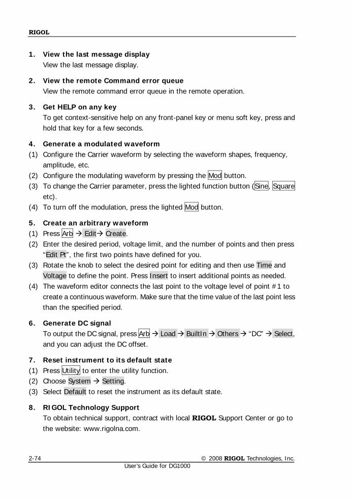
RIGOL
© 2008 RIGOL Technologies, Inc. User’s Guide for DG1000
2-74
1. View the last message display
View the last message display.
2. View the remote Command error queue View the remote command error queue in the remote operation.
3. Get HELP on any key To get context-sensitive help on any front-panel key or menu soft key, press and hold that key for a few seconds.
4. Generate a modulated waveform (1) Configure the Carrier waveform by selecting the waveform shapes, frequency,
amplitude, etc. (2) Configure the modulating waveform by pressing the Mod button. (3) To change the Carrier parameter, press the lighted function button (Sine, Square
etc). (4) To turn off the modulation, press the lighted Mod button.
5. Create an arbitrary waveform (1) Press Arb Edit Create. (2) Enter the desired period, voltage limit, and the number of points and then press
“Edit Pt”, the first two points have defined for you. (3) Rotate the knob to select the desired point for editing and then use Time and
Voltage to define the point. Press Insert to insert additional points as needed. (4) The waveform editor connects the last point to the voltage level of point #1 to
create a continuous waveform. Make sure that the time value of the last point less than the specified period.
6. Generate DC signal To output the DC signal, press Arb Load BuiltIn Others “DC” Select, and you can adjust the DC offset.
7. Reset instrument to its default state (1) Press Utility to enter the utility function. (2) Choose System Setting. (3) Select Default to reset the instrument as its default state.
8. RIGOL Technology Support To obtain technical support, contract with local RIGOL Support Center or go to the website: www.rigolna.com.
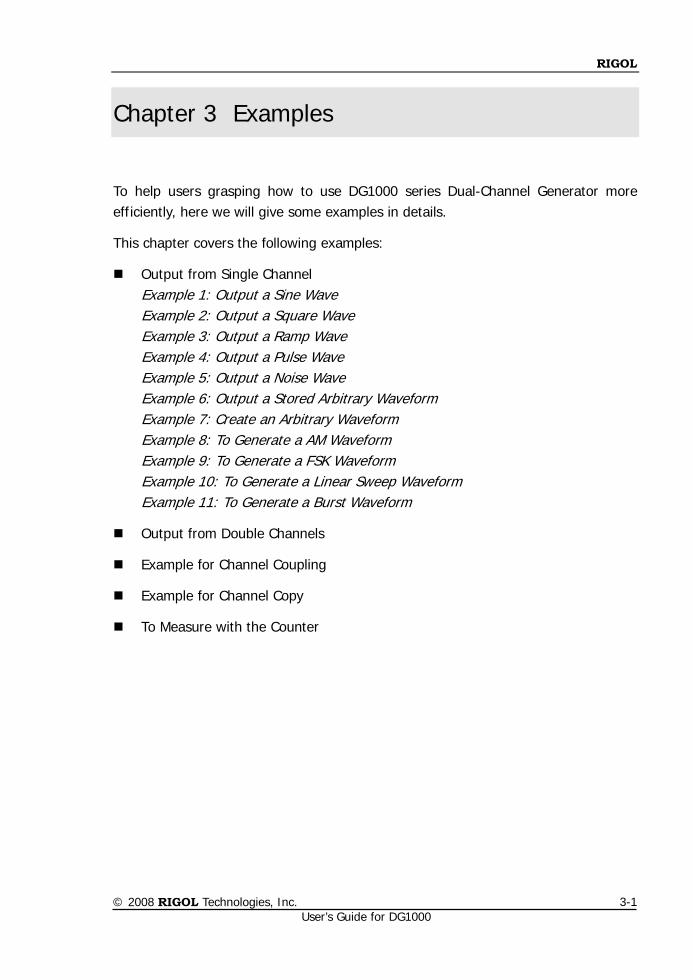
RIGOL
© 2008 RIGOL Technologies, Inc. User’s Guide for DG1000
3-1
Chapter 3 Examples
To help users grasping how to use DG1000 series Dual-Channel Generator more efficiently, here we will give some examples in details.
This chapter covers the following examples:
Output from Single Channel Example 1: Output a Sine Wave
Example 2: Output a Square Wave Example 3: Output a Ramp Wave Example 4: Output a Pulse Wave Example 5: Output a Noise Wave Example 6: Output a Stored Arbitrary Waveform Example 7: Create an Arbitrary Waveform Example 8: To Generate a AM Waveform Example 9: To Generate a FSK Waveform Example 10: To Generate a Linear Sweep Waveform Example 11: To Generate a Burst Waveform
Output from Double Channels
Example for Channel Coupling
Example for Channel Copy
To Measure with the Counter
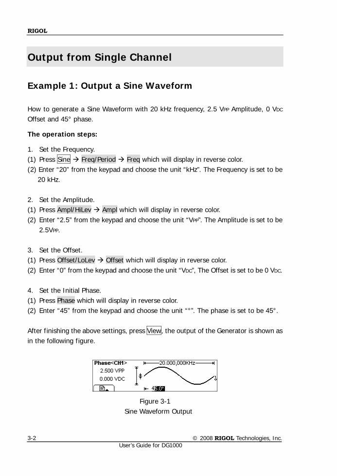
RIGOL
© 2008 RIGOL Technologies, Inc. User’s Guide for DG1000
3-2
Output from Single Channel
Example 1: Output a Sine Waveform
How to generate a Sine Waveform with 20 kHz frequency, 2.5 VPP Amplitude, 0 VDC Offset and 45° phase.
The operation steps:
1. Set the Frequency. (1) Press Sine Freq/Period Freq which will display in reverse color. (2) Enter “20” from the keypad and choose the unit “kHz”. The Frequency is set to be
20 kHz. 2. Set the Amplitude. (1) Press Ampl/HiLev Ampl which will display in reverse color. (2) Enter “2.5” from the keypad and choose the unit “VPP”. The Amplitude is set to be
2.5VPP. 3. Set the Offset. (1) Press Offset/LoLev Offset which will display in reverse color. (2) Enter “0” from the keypad and choose the unit “VDC”, The Offset is set to be 0 VDC. 4. Set the Initial Phase. (1) Press Phase which will display in reverse color. (2) Enter “45” from the keypad and choose the unit “°”. The phase is set to be 45°.
After finishing the above settings, press View, the output of the Generator is shown as in the following figure.
Figure 3-1 Sine Waveform Output
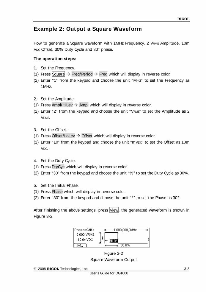
RIGOL
© 2008 RIGOL Technologies, Inc. User’s Guide for DG1000
3-3
Example 2: Output a Square Waveform
How to generate a Square waveform with 1MHz Frequency, 2 VRMS Amplitude, 10m VDC Offset, 30% Duty Cycle and 30° phase.
The operation steps:
1. Set the Frequency. (1) Press Square Freq/Period Freq which will display in reverse color. (2) Enter “1” from the keypad and choose the unit “MHz” to set the Frequency as
1MHz. 2. Set the Amplitude. (1) Press Ampl/HiLev Ampl which will display in reverse color. (2) Enter “2” from the keypad and choose the unit “VRMS” to set the Amplitude as 2
VRMS. 3. Set the Offset. (1) Press Offset/LoLev Offset which will display in reverse color. (2) Enter “10” from the keypad and choose the unit “mVDC” to set the Offset as 10m
VDC. 4. Set the Duty Cycle. (1) Press DtyCyc which will display in reverse color. (2) Enter “30” from the keypad and choose the unit “%” to set the Duty Cycle as 30%. 5. Set the Initial Phase. (1) Press Phase which will display in reverse color. (2) Enter “30” from the keypad and choose the unit “°” to set the Phase as 30°. After finishing the above settings, press View, the generated waveform is shown in Figure 3-2.
Figure 3-2 Square Waveform Output
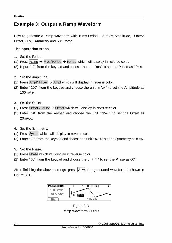
RIGOL
© 2008 RIGOL Technologies, Inc. User’s Guide for DG1000
3-4
Example 3: Output a Ramp Waveform
How to generate a Ramp waveform with 10ms Period, 100mVPP Amplitude, 20mVDC Offset, 80% Symmetry and 60° Phase.
The operation steps:
1. Set the Period. (1) Press Ramp Freq/Period Period which will display in reverse color. (2) Input “10” from the keypad and choose the unit “ms” to set the Period as 10ms. 2. Set the Amplitude. (1) Press Ampl/ HiLev Ampl which will display in reverse color. (2) Enter “100” from the keypad and choose the unit “mVPP” to set the Amplitude as
100mVPP. 3. Set the Offset. (1) Press Offset /LoLev Offset which will display in reverse color. (2) Enter “20” from the keypad and choose the unit “mVDC” to set the Offset as
20mVDC. 4. Set the Symmetry. (1) Press Symm which will display in reverse color. (2) Enter “80” from the keypad and choose the unit “%” to set the Symmetry as 80%.
5. Set the Phase. (1) Press Phase which will display in reverse color. (2) Enter “60” from the keypad and choose the unit “°” to set the Phase as 60°. After finishing the above settings, press View, the generated waveform is shown in Figure 3-3.
Figure 3-3 Ramp Waveform Output
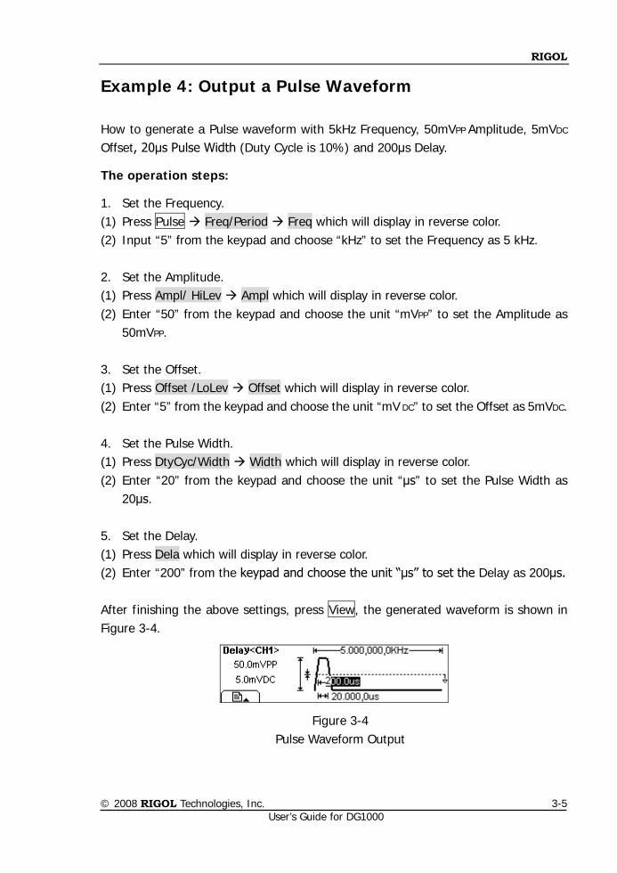
RIGOL
© 2008 RIGOL Technologies, Inc. User’s Guide for DG1000
3-5
Example 4: Output a Pulse Waveform
How to generate a Pulse waveform with 5kHz Frequency, 50mVPP Amplitude, 5mVDC Offset, 20μs Pulse Width (Duty Cycle is 10%) and 200μs Delay.
The operation steps:
1. Set the Frequency. (1) Press Pulse Freq/Period Freq which will display in reverse color. (2) Input “5” from the keypad and choose “kHz” to set the Frequency as 5 kHz. 2. Set the Amplitude. (1) Press Ampl/ HiLev Ampl which will display in reverse color. (2) Enter “50” from the keypad and choose the unit “mVPP” to set the Amplitude as
50mVPP. 3. Set the Offset. (1) Press Offset /LoLev Offset which will display in reverse color. (2) Enter “5” from the keypad and choose the unit “mV DC” to set the Offset as 5mVDC. 4. Set the Pulse Width. (1) Press DtyCyc/Width Width which will display in reverse color. (2) Enter “20” from the keypad and choose the unit “μs” to set the Pulse Width as
20μs.
5. Set the Delay. (1) Press Dela which will display in reverse color. (2) Enter “200” from the keypad and choose the unit “μs” to set the Delay as 200μs. After finishing the above settings, press View, the generated waveform is shown in Figure 3-4.
Figure 3-4 Pulse Waveform Output
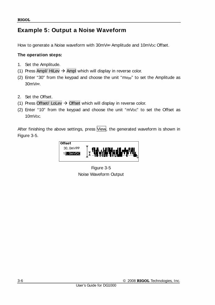
RIGOL
© 2008 RIGOL Technologies, Inc. User’s Guide for DG1000
3-6
Example 5: Output a Noise Waveform
How to generate a Noise waveform with 30mVPP Amplitude and 10mVDC Offset.
The operation steps:
1. Set the Amplitude. (1) Press Ampl/ HiLev Ampl which will display in reverse color. (2) Enter “30” from the keypad and choose the unit “mvpp” to set the Amplitude as
30mVPP.
2. Set the Offset. (1) Press Offset/ LoLev Offset which will display in reverse color. (2) Enter “10” from the keypad and choose the unit “mVDC” to set the Offset as
10mVDC. After finishing the above settings, press View, the generated waveform is shown in Figure 3-5.
Figure 3-5 Noise Waveform Output
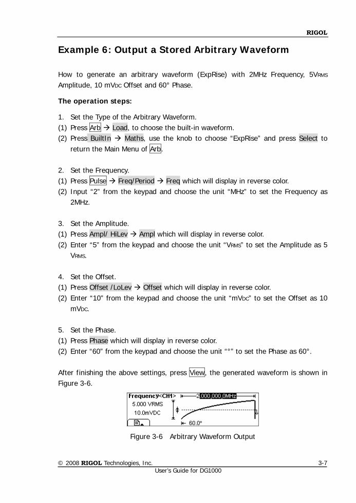
RIGOL
© 2008 RIGOL Technologies, Inc. User’s Guide for DG1000
3-7
Example 6: Output a Stored Arbitrary Waveform
How to generate an arbitrary waveform (ExpRise) with 2MHz Frequency, 5VRMS
Amplitude, 10 mVDC Offset and 60° Phase.
The operation steps:
1. Set the Type of the Arbitrary Waveform. (1) Press Arb Load, to choose the built-in waveform. (2) Press BuiltIn Maths, use the knob to choose “ExpRise” and press Select to
return the Main Menu of Arb. 2. Set the Frequency. (1) Press Pulse Freq/Period Freq which will display in reverse color. (2) Input “2” from the keypad and choose the unit “MHz” to set the Frequency as
2MHz. 3. Set the Amplitude. (1) Press Ampl/ HiLev Ampl which will display in reverse color. (2) Enter “5” from the keypad and choose the unit “VRMS” to set the Amplitude as 5
VRMS. 4. Set the Offset. (1) Press Offset /LoLev Offset which will display in reverse color. (2) Enter “10” from the keypad and choose the unit “mVDC” to set the Offset as 10
mVDC.
5. Set the Phase. (1) Press Phase which will display in reverse color. (2) Enter “60” from the keypad and choose the unit “°” to set the Phase as 60°. After finishing the above settings, press View, the generated waveform is shown in Figure 3-6.
Figure 3-6 Arbitrary Waveform Output
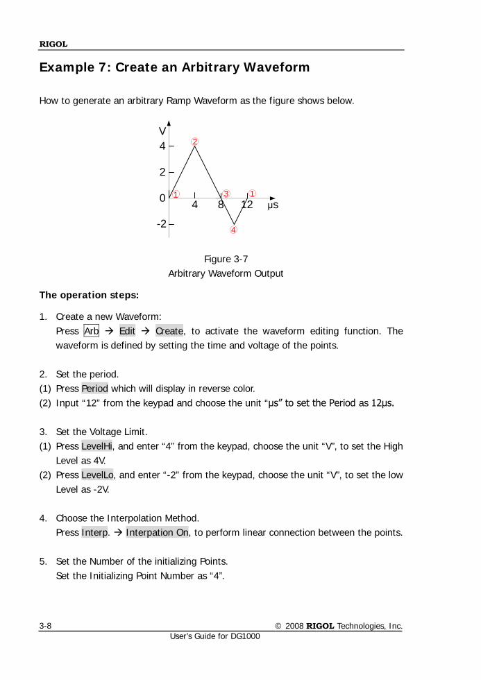
RIGOL
© 2008 RIGOL Technologies, Inc. User’s Guide for DG1000
3-8
Example 7: Create an Arbitrary Waveform
How to generate an arbitrary Ramp Waveform as the figure shows below.
4 8 12
2
4
μs0 1
4
3
2
1
-2
V
Figure 3-7 Arbitrary Waveform Output
The operation steps:
1. Create a new Waveform: Press Arb Edit Create, to activate the waveform editing function. The waveform is defined by setting the time and voltage of the points.
2. Set the period. (1) Press Period which will display in reverse color. (2) Input “12” from the keypad and choose the unit “μs” to set the Period as 12μs. 3. Set the Voltage Limit. (1) Press LevelHi, and enter “4” from the keypad, choose the unit “V”, to set the High
Level as 4V. (2) Press LevelLo, and enter “-2” from the keypad, choose the unit “V”, to set the low
Level as -2V.
4. Choose the Interpolation Method. Press Interp. Interpation On, to perform linear connection between the points.
5. Set the Number of the initializing Points. Set the Initializing Point Number as “4”.
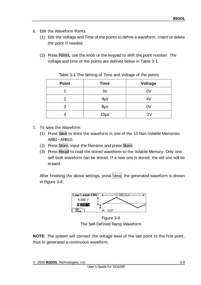
RIGOL
© 2008 RIGOL Technologies, Inc. User’s Guide for DG1000
3-9
6. Edit the Waveform Points.
(1) Edit the Voltage and Time of the points to define a waveform. Insert or delete the point If needed.
(2) Press Points, use the knob or the keypad to shift the point number. The
voltage and time of the points are defined below in Table 3-1.
Table 3-1 The Setting of Time and Voltage of the points
Point Time Voltage
1 0s 0V
2 4μs 4V
3 8μs 0V
4 10μs -2V
7. To save the Waveform.
(1) Press Save to store the waveform in one of the 10 Non-Volatile Memories: ARB1~ARB10.
(2) Press Store, input the filename and press Store. (3) Press Recall to read the stored waveform to the Volatile Memory. Only one
self-built waveform can be stored. If a new one is stored, the old one will be erased.
After finishing the above settings, press View, the generated waveform is shown in Figure 3-8.
Figure 3-8 The Self-Defined Ramp Waveform
NOTE: The system will connect the voltage level of the last point to the first point, thus to generated a continuous waveform.
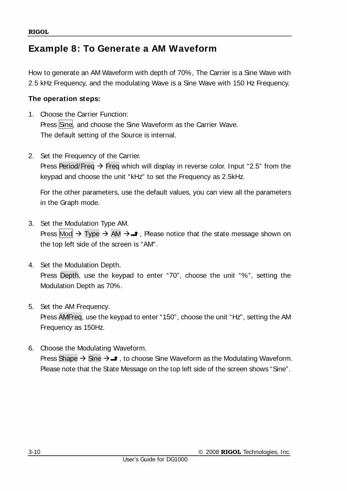
RIGOL
© 2008 RIGOL Technologies, Inc. User’s Guide for DG1000
3-10
Example 8: To Generate a AM Waveform
How to generate an AM Waveform with depth of 70%, The Carrier is a Sine Wave with 2.5 kHz Frequency, and the modulating Wave is a Sine Wave with 150 Hz Frequency.
The operation steps:
1. Choose the Carrier Function: Press Sine, and choose the Sine Waveform as the Carrier Wave. The default setting of the Source is internal.
2. Set the Frequency of the Carrier.
Press Period/Freq Freq which will display in reverse color. Input “2.5” from the keypad and choose the unit “kHz” to set the Frequency as 2.5kHz.
For the other parameters, use the default values, you can view all the parameters in the Graph mode.
3. Set the Modulation Type AM.
Press Mod Type AM , Please notice that the state message shown on the top left side of the screen is “AM”.
4. Set the Modulation Depth. Press Depth, use the keypad to enter “70”, choose the unit “%”, setting the Modulation Depth as 70%.
5. Set the AM Frequency.
Press AMFreq, use the keypad to enter “150”, choose the unit “Hz”, setting the AM Frequency as 150Hz.
6. Choose the Modulating Waveform.
Press Shape Sine , to choose Sine Waveform as the Modulating Waveform. Please note that the State Message on the top left side of the screen shows “Sine”.
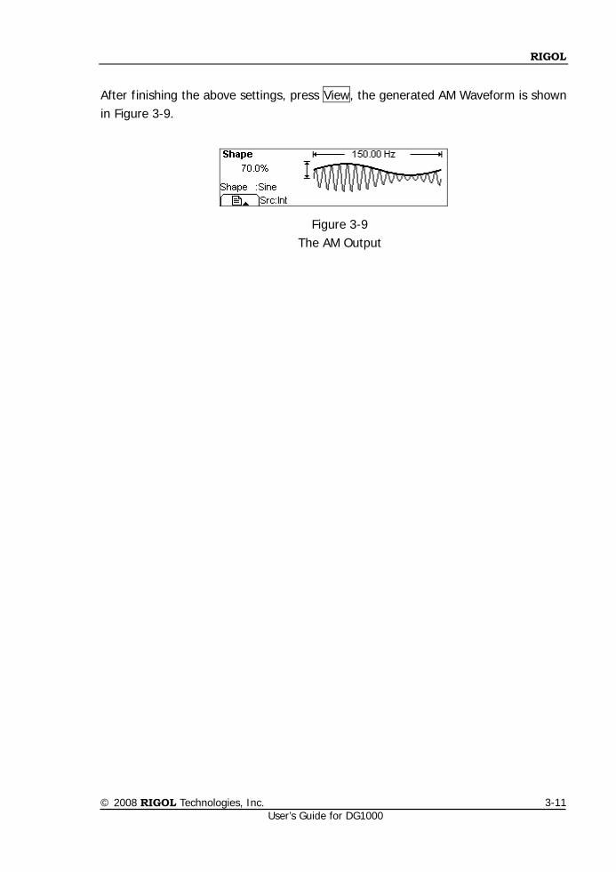
RIGOL
© 2008 RIGOL Technologies, Inc. User’s Guide for DG1000
3-11
After finishing the above settings, press View, the generated AM Waveform is shown in Figure 3-9.
Figure 3-9 The AM Output
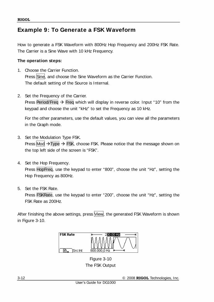
RIGOL
© 2008 RIGOL Technologies, Inc. User’s Guide for DG1000
3-12
Example 9: To Generate a FSK Waveform
How to generate a FSK Waveform with 800Hz Hop Frequency and 200Hz FSK Rate. The Carrier is a Sine Wave with 10 kHz Frequency.
The operation steps:
1. Choose the Carrier Function. Press Sine, and choose the Sine Waveform as the Carrier Function. The default setting of the Source is Internal.
2. Set the Frequency of the Carrier. Press Period/Freq Freq which will display in reverse color. Input “10” from the keypad and choose the unit “kHz” to set the Frequency as 10 kHz.
For the other parameters, use the default values, you can view all the parameters in the Graph mode.
3. Set the Modulation Type FSK.
Press Mod Type FSK, choose FSK. Please notice that the message shown on the top left side of the screen is “FSK”.
4. Set the Hop Frequency.
Press HopFreq, use the keypad to enter “800”, choose the unit “Hz”, setting the Hop Frequency as 800Hz.
5. Set the FSK Rate. Press FSKRate, use the keypad to enter “200”, choose the unit “Hz”, setting the FSK Rate as 200Hz.
After finishing the above settings, press View, the generated FSK Waveform is shown in Figure 3-10.
Figure 3-10 The FSK Output
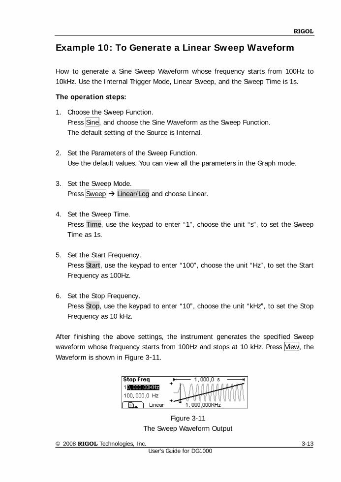
RIGOL
© 2008 RIGOL Technologies, Inc. User’s Guide for DG1000
3-13
Example 10: To Generate a Linear Sweep Waveform
How to generate a Sine Sweep Waveform whose frequency starts from 100Hz to 10kHz. Use the Internal Trigger Mode, Linear Sweep, and the Sweep Time is 1s.
The operation steps:
1. Choose the Sweep Function. Press Sine, and choose the Sine Waveform as the Sweep Function. The default setting of the Source is Internal.
2. Set the Parameters of the Sweep Function.
Use the default values. You can view all the parameters in the Graph mode.
3. Set the Sweep Mode. Press Sweep Linear/Log and choose Linear.
4. Set the Sweep Time. Press Time, use the keypad to enter “1”, choose the unit “s”, to set the Sweep Time as 1s.
5. Set the Start Frequency.
Press Start, use the keypad to enter “100”, choose the unit “Hz”, to set the Start Frequency as 100Hz.
6. Set the Stop Frequency.
Press Stop, use the keypad to enter “10”, choose the unit “kHz”, to set the Stop Frequency as 10 kHz.
After finishing the above settings, the instrument generates the specified Sweep waveform whose frequency starts from 100Hz and stops at 10 kHz. Press View, the Waveform is shown in Figure 3-11.
Figure 3-11 The Sweep Waveform Output
RIGOL
© 2008 RIGOL Technologies, Inc. User’s Guide for DG1000
3-14
Instructions
If necessary, you can set the frequency Limits by setting the Center Frequency and the frequency range. These parameters are similar to the Start and Stop frequency, which will provide more flexibility for you. To generate the same waveform, set the Center Frequency to be 5.050 kHz, the frequency range is 9.900 kHz.
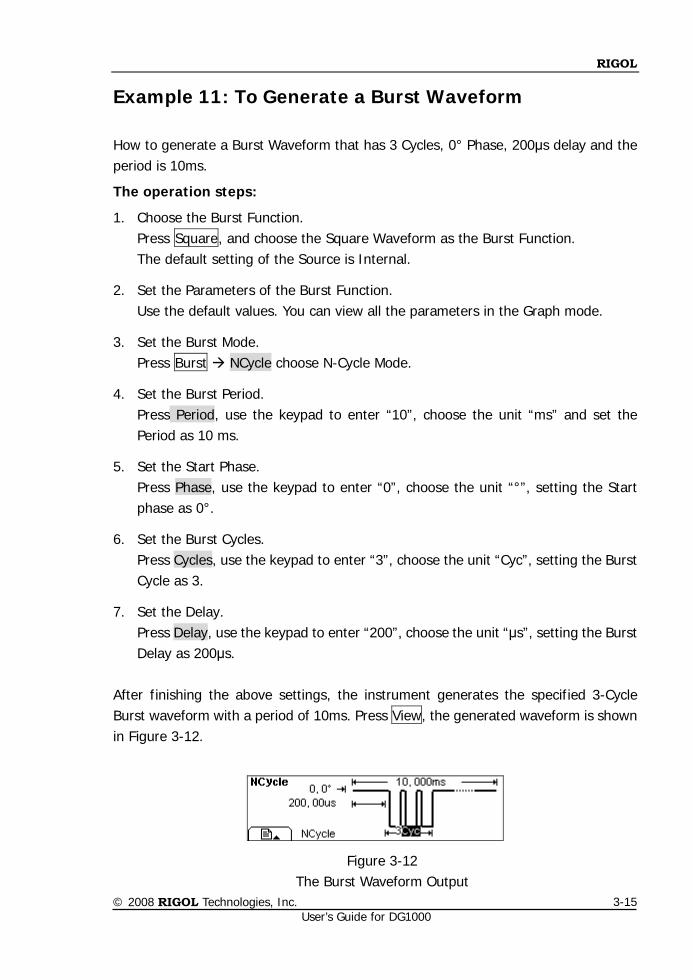
RIGOL
© 2008 RIGOL Technologies, Inc. User’s Guide for DG1000
3-15
Example 11: To Generate a Burst Waveform
How to generate a Burst Waveform that has 3 Cycles, 0° Phase, 200μs delay and the period is 10ms.
The operation steps:
1. Choose the Burst Function. Press Square, and choose the Square Waveform as the Burst Function. The default setting of the Source is Internal.
2. Set the Parameters of the Burst Function. Use the default values. You can view all the parameters in the Graph mode.
3. Set the Burst Mode. Press Burst NCycle choose N-Cycle Mode.
4. Set the Burst Period. Press Period, use the keypad to enter “10”, choose the unit “ms” and set the Period as 10 ms.
5. Set the Start Phase. Press Phase, use the keypad to enter “0”, choose the unit “°”, setting the Start phase as 0°.
6. Set the Burst Cycles. Press Cycles, use the keypad to enter “3”, choose the unit “Cyc”, setting the Burst Cycle as 3.
7. Set the Delay. Press Delay, use the keypad to enter “200”, choose the unit “μs”, setting the Burst Delay as 200μs.
After finishing the above settings, the instrument generates the specified 3-Cycle Burst waveform with a period of 10ms. Press View, the generated waveform is shown in Figure 3-12.
Figure 3-12 The Burst Waveform Output
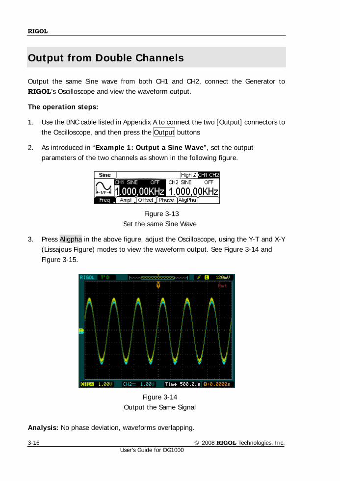
RIGOL
© 2008 RIGOL Technologies, Inc. User’s Guide for DG1000
3-16
Output from Double Channels
Output the same Sine wave from both CH1 and CH2, connect the Generator to RIGOL’s Oscilloscope and view the waveform output.
The operation steps:
1. Use the BNC cable listed in Appendix A to connect the two [Output] connectors to the Oscilloscope, and then press the Output buttons
2. As introduced in “Example 1: Output a Sine Wave”, set the output parameters of the two channels as shown in the following figure.
Figure 3-13
Set the same Sine Wave
3. Press Aligpha in the above figure, adjust the Oscilloscope, using the Y-T and X-Y (Lissajous Figure) modes to view the waveform output. See Figure 3-14 and Figure 3-15.
Figure 3-14 Output the Same Signal
Analysis: No phase deviation, waveforms overlapping.
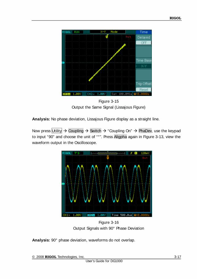
RIGOL
© 2008 RIGOL Technologies, Inc. User’s Guide for DG1000
3-17
Figure 3-15 Output the Same Signal (Lissajous Figure)
Analysis: No phase deviation, Lissajous Figure display as a straight line. Now press Utility Coupling Switch “Coupling On” PhaDev, use the keypad to input “90” and choose the unit of “°”. Press Aligpha again in Figure 3-13, view the waveform output in the Oscilloscope.
Figure 3-16 Output Signals with 90° Phase Deviation
Analysis: 90° phase deviation, waveforms do not overlap.
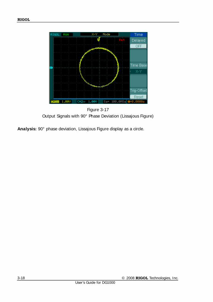
RIGOL
© 2008 RIGOL Technologies, Inc. User’s Guide for DG1000
3-18
Figure 3-17 Output Signals with 90° Phase Deviation (Lissajous Figure)
Analysis: 90° phase deviation, Lissajous Figure display as a circle.
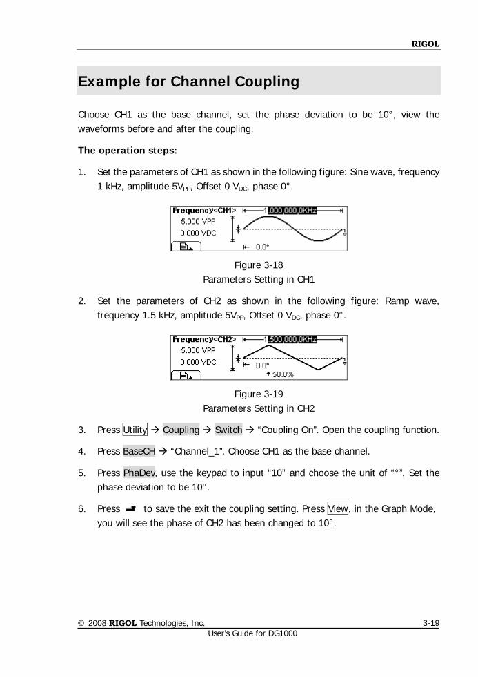
RIGOL
© 2008 RIGOL Technologies, Inc. User’s Guide for DG1000
3-19
Example for Channel Coupling
Choose CH1 as the base channel, set the phase deviation to be 10°, view the waveforms before and after the coupling.
The operation steps:
1. Set the parameters of CH1 as shown in the following figure: Sine wave, frequency 1 kHz, amplitude 5VPP, Offset 0 VDC, phase 0°.
Figure 3-18 Parameters Setting in CH1
2. Set the parameters of CH2 as shown in the following figure: Ramp wave, frequency 1.5 kHz, amplitude 5VPP, Offset 0 VDC, phase 0°.
Figure 3-19 Parameters Setting in CH2
3. Press Utility Coupling Switch “Coupling On”. Open the coupling function.
4. Press BaseCH “Channel_1”. Choose CH1 as the base channel.
5. Press PhaDev, use the keypad to input “10” and choose the unit of “°”. Set the phase deviation to be 10°.
6. Press to save the exit the coupling setting. Press View, in the Graph Mode, you will see the phase of CH2 has been changed to 10°.
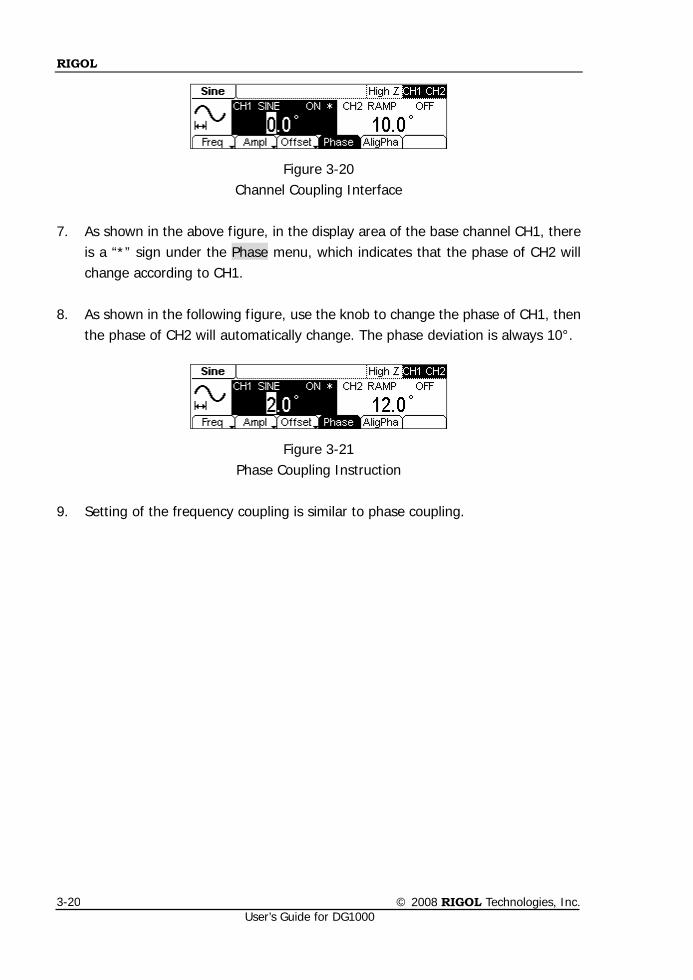
RIGOL
© 2008 RIGOL Technologies, Inc. User’s Guide for DG1000
3-20
Figure 3-20 Channel Coupling Interface
7. As shown in the above figure, in the display area of the base channel CH1, there
is a “*” sign under the Phase menu, which indicates that the phase of CH2 will change according to CH1.
8. As shown in the following figure, use the knob to change the phase of CH1, then the phase of CH2 will automatically change. The phase deviation is always 10°.
Figure 3-21 Phase Coupling Instruction
9. Setting of the frequency coupling is similar to phase coupling.
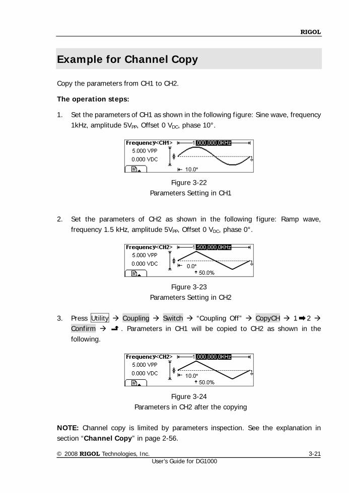
RIGOL
© 2008 RIGOL Technologies, Inc. User’s Guide for DG1000
3-21
Example for Channel Copy
Copy the parameters from CH1 to CH2.
The operation steps:
1. Set the parameters of CH1 as shown in the following figure: Sine wave, frequency 1kHz, amplitude 5VPP, Offset 0 VDC, phase 10°.
Figure 3-22 Parameters Setting in CH1
2. Set the parameters of CH2 as shown in the following figure: Ramp wave,
frequency 1.5 kHz, amplitude 5VPP, Offset 0 VDC, phase 0°.
Figure 3-23 Parameters Setting in CH2
3. Press Utility Coupling Switch “Coupling Off” CopyCH 1 2
Confirm . Parameters in CH1 will be copied to CH2 as shown in the following.
Figure 3-24 Parameters in CH2 after the copying
NOTE: Channel copy is limited by parameters inspection. See the explanation in section “Channel Copy” in page 2-56.
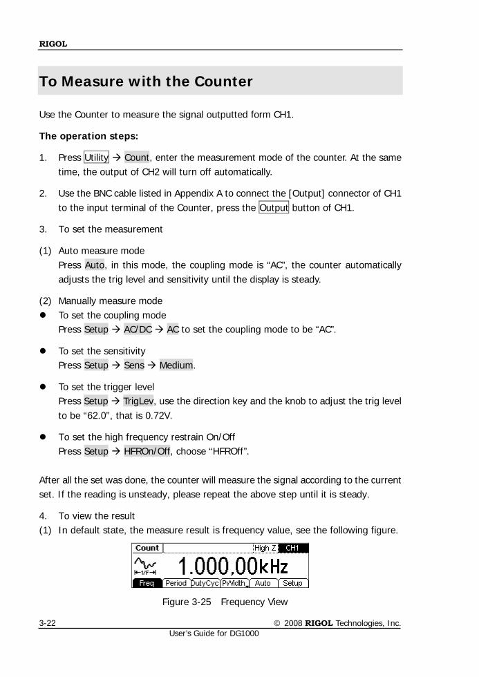
RIGOL
© 2008 RIGOL Technologies, Inc. User’s Guide for DG1000
3-22
To Measure with the Counter
Use the Counter to measure the signal outputted form CH1.
The operation steps:
1. Press Utility Count, enter the measurement mode of the counter. At the same time, the output of CH2 will turn off automatically.
2. Use the BNC cable listed in Appendix A to connect the [Output] connector of CH1 to the input terminal of the Counter, press the Output button of CH1.
3. To set the measurement
(1) Auto measure mode Press Auto, in this mode, the coupling mode is “AC”, the counter automatically adjusts the trig level and sensitivity until the display is steady.
(2) Manually measure mode To set the coupling mode
Press Setup AC/DC AC to set the coupling mode to be “AC”.
To set the sensitivity Press Setup Sens Medium.
To set the trigger level Press Setup TrigLev, use the direction key and the knob to adjust the trig level to be “62.0”, that is 0.72V.
To set the high frequency restrain On/Off Press Setup HFROn/Off, choose “HFROff”.
After all the set was done, the counter will measure the signal according to the current set. If the reading is unsteady, please repeat the above step until it is steady.
4. To view the result (1) In default state, the measure result is frequency value, see the following figure.
Figure 3-25 Frequency View
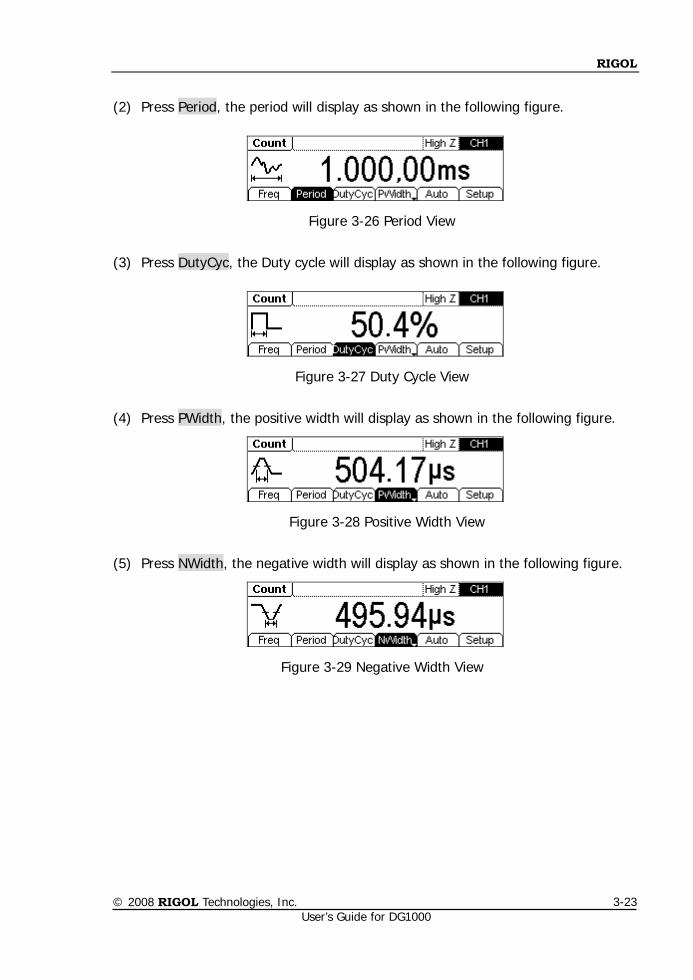
RIGOL
© 2008 RIGOL Technologies, Inc. User’s Guide for DG1000
3-23
(2) Press Period, the period will display as shown in the following figure.
Figure 3-26 Period View
(3) Press DutyCyc, the Duty cycle will display as shown in the following figure.
Figure 3-27 Duty Cycle View
(4) Press PWidth, the positive width will display as shown in the following figure.
Figure 3-28 Positive Width View
(5) Press NWidth, the negative width will display as shown in the following figure.
Figure 3-29 Negative Width View

RIGOL
© 2008 RIGOL Technologies, Inc. User’s Guide for DG1000
4-1
Chapter 4 Prompt Messages & Troubleshooting
This chapter covers the following topics:
Prompting Messages Common Messages Error Messages Data Overflow
Troubleshooting
RIGOL
© 2008 RIGOL Technologies, Inc. User’s Guide for DG1000
4-2
Prompting Messages
Common Messages
1. Need Help? Press and hold down any key. Settings are restored from last power-down. Selected interface is USB. When the instrument is powered, this message will appear to inform users that all the settings have been restored and you can operate the instrument normally. The instrument detected current I/O is USB, and informs the user that no new USB device is detected.
2. No changes. When the waveform parameter is being altered, if the user cancels the operation, the message will prompt.
3. Selected Arb is ***. Press Arb, this message will appear to inform users that the default selection of arbitrary waveform type is “***”.
4. First, set the all over waveform parameters. To inform the user, set the general waveform parameter first. Then set the parameters for each point.
5. Editing the existing waveform parameters. Perform the waveform edit operation, and inform the user that operation can be taken to edit the current waveform parameter.
6. Trigger ignored-OUTPUT is off. When the OUTPUT is disabled, the Trigger Output will be disabled automatically.
7. Instrument is triggered. Press Sweep / Burst Trigger Source Manual, this message will appear to inform users that the instrument has performed a trigger.
8. Press any F key to redisplay menu when it disappears. When menu disappeared, press any menu key will recall it.
9. Burst period increased to fit entire burst.
RIGOL
© 2008 RIGOL Technologies, Inc. User’s Guide for DG1000
4-3
The PRI of Period is higher than that of the Burst Period. As long as the burst period does not reach its maximum, the generator will increase the burst period to cater to the need of the specific burst cycle or waveform frequency.
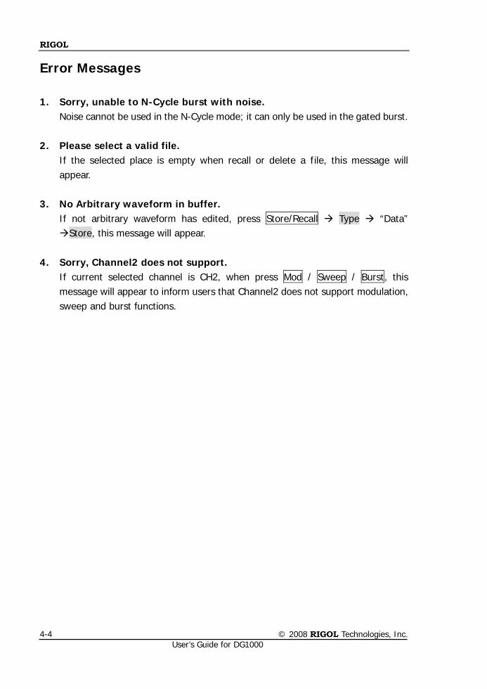
RIGOL
© 2008 RIGOL Technologies, Inc. User’s Guide for DG1000
4-4
Error Messages
1. Sorry, unable to N-Cycle burst with noise. Noise cannot be used in the N-Cycle mode; it can only be used in the gated burst.
2. Please select a valid file. If the selected place is empty when recall or delete a file, this message will appear.
3. No Arbitrary waveform in buffer.
If not arbitrary waveform has edited, press Store/Recall Type “Data” Store, this message will appear.
4. Sorry, Channel2 does not support. If current selected channel is CH2, when press Mod / Sweep / Burst, this message will appear to inform users that Channel2 does not support modulation, sweep and burst functions.
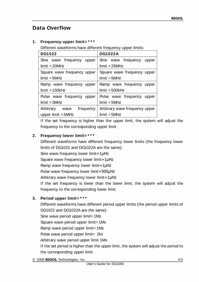
RIGOL
© 2008 RIGOL Technologies, Inc. User’s Guide for DG1000
4-5
Data Overflow
1. Frequency upper limit=*** Different waveforms have different frequency upper limits: DG1022 DG1022A Sine wave frequency upper limit =20MHz
Sine wave frequency upper limit =25MHz
Square wave frequency upper limit =5MHz
Square wave frequency upper limit =5MHz
Ramp wave frequency upper limit =150kHz
Ramp wave frequency upper limit =500kHz
Pulse wave frequency upper limit =3MHz
Pulse wave frequency upper limit =5MHz
Arbitrary wave frequency upper limit =5MHz
Arbitrary wave frequency upper limit =5MHz
If the set frequency is higher than the upper limit, the system will adjust the frequency to the corresponding upper limit.
2. Frequency lower limit=*** Different waveforms have different frequency lower limits (the frequency lower limits of DG1022 and DG1022A are the same): Sine wave frequency lower limit=1μHz Square wave frequency lower limit=1μHz Ramp wave frequency lower limit=1μHz Pulse wave frequency lower limit=500μHz Arbitrary wave frequency lower limit=1μHz If the set frequency is lower than the lower limit, the system will adjust the frequency to the corresponding lower limit.
3. Period upper limit=*** Different waveforms have different period upper limits (the period upper limits of DG1022 and DG1022A are the same): Sine wave period upper limit=1Ms Square wave period upper limit=1Ms Ramp wave period upper limit=1Ms Pulse wave period upper limit= 2ks Arbitrary wave period upper limit 1Ms If the set period is higher than the upper limit, the system will adjust the period to the corresponding upper limit.
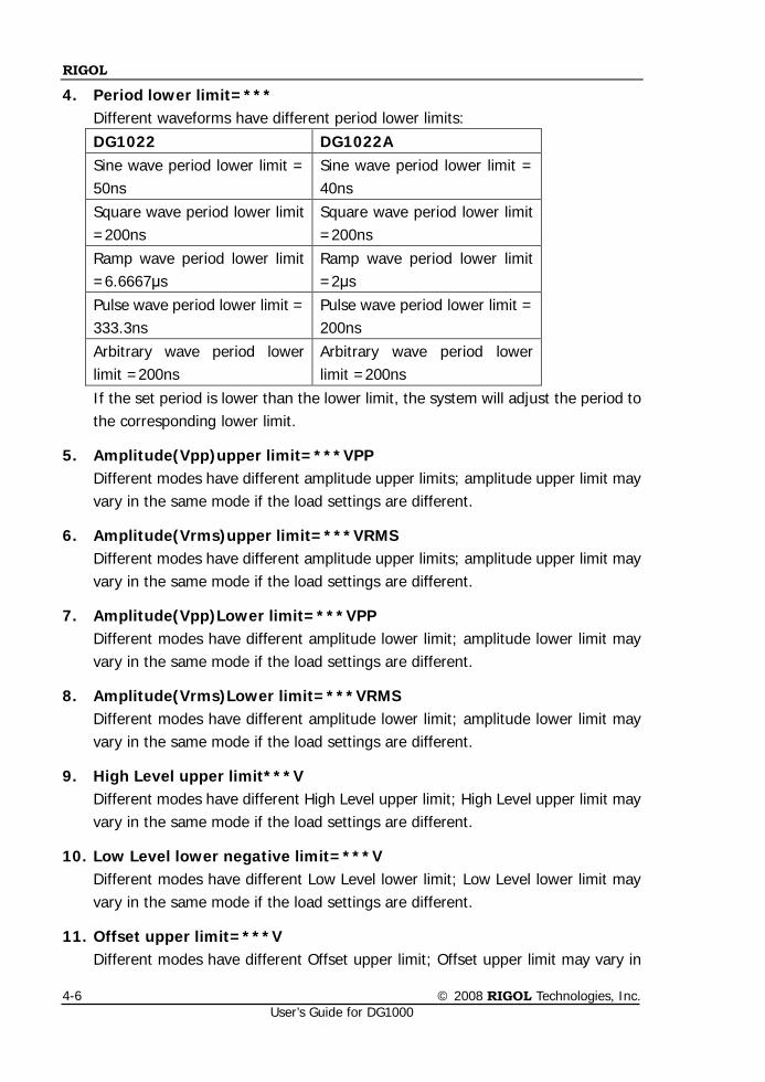
RIGOL
© 2008 RIGOL Technologies, Inc. User’s Guide for DG1000
4-6
4. Period lower limit=*** Different waveforms have different period lower limits: DG1022 DG1022A Sine wave period lower limit = 50ns
Sine wave period lower limit = 40ns
Square wave period lower limit =200ns
Square wave period lower limit =200ns
Ramp wave period lower limit =6.6667μs
Ramp wave period lower limit =2μs
Pulse wave period lower limit = 333.3ns
Pulse wave period lower limit = 200ns
Arbitrary wave period lower limit =200ns
Arbitrary wave period lower limit =200ns
If the set period is lower than the lower limit, the system will adjust the period to the corresponding lower limit.
5. Amplitude(Vpp)upper limit=***VPP Different modes have different amplitude upper limits; amplitude upper limit may vary in the same mode if the load settings are different.
6. Amplitude(Vrms)upper limit=***VRMS Different modes have different amplitude upper limits; amplitude upper limit may vary in the same mode if the load settings are different.
7. Amplitude(Vpp)Lower limit=***VPP Different modes have different amplitude lower limit; amplitude lower limit may vary in the same mode if the load settings are different.
8. Amplitude(Vrms)Lower limit=***VRMS Different modes have different amplitude lower limit; amplitude lower limit may vary in the same mode if the load settings are different.
9. High Level upper limit***V Different modes have different High Level upper limit; High Level upper limit may vary in the same mode if the load settings are different.
10. Low Level lower negative limit=***V Different modes have different Low Level lower limit; Low Level lower limit may vary in the same mode if the load settings are different.
11. Offset upper limit=***V Different modes have different Offset upper limit; Offset upper limit may vary in
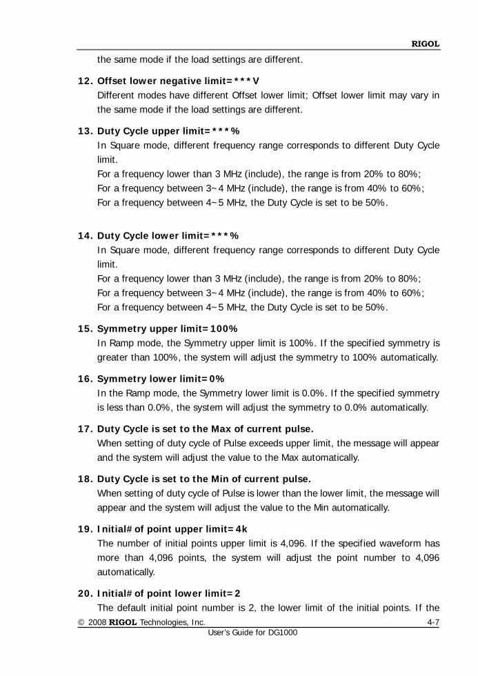
RIGOL
© 2008 RIGOL Technologies, Inc. User’s Guide for DG1000
4-7
the same mode if the load settings are different.
12. Offset lower negative limit=***V Different modes have different Offset lower limit; Offset lower limit may vary in the same mode if the load settings are different.
13. Duty Cycle upper limit=***% In Square mode, different frequency range corresponds to different Duty Cycle limit. For a frequency lower than 3 MHz (include), the range is from 20% to 80%; For a frequency between 3~4 MHz (include), the range is from 40% to 60%; For a frequency between 4~5 MHz, the Duty Cycle is set to be 50%.
14. Duty Cycle lower limit=***% In Square mode, different frequency range corresponds to different Duty Cycle limit. For a frequency lower than 3 MHz (include), the range is from 20% to 80%; For a frequency between 3~4 MHz (include), the range is from 40% to 60%; For a frequency between 4~5 MHz, the Duty Cycle is set to be 50%.
15. Symmetry upper limit=100% In Ramp mode, the Symmetry upper limit is 100%. If the specified symmetry is greater than 100%, the system will adjust the symmetry to 100% automatically.
16. Symmetry lower limit=0% In the Ramp mode, the Symmetry lower limit is 0.0%. If the specified symmetry is less than 0.0%, the system will adjust the symmetry to 0.0% automatically.
17. Duty Cycle is set to the Max of current pulse. When setting of duty cycle of Pulse exceeds upper limit, the message will appear and the system will adjust the value to the Max automatically.
18. Duty Cycle is set to the Min of current pulse. When setting of duty cycle of Pulse is lower than the lower limit, the message will appear and the system will adjust the value to the Min automatically.
19. Initial#of point upper limit=4k The number of initial points upper limit is 4,096. If the specified waveform has more than 4,096 points, the system will adjust the point number to 4,096 automatically.
20. Initial#of point lower limit=2 The default initial point number is 2, the lower limit of the initial points. If the
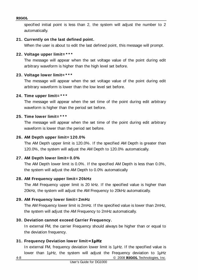
RIGOL
© 2008 RIGOL Technologies, Inc. User’s Guide for DG1000
4-8
specified initial point is less than 2, the system will adjust the number to 2 automatically.
21. Currently on the last defined point. When the user is about to edit the last defined point, this message will prompt.
22. Voltage upper limit=*** The message will appear when the set voltage value of the point during edit arbitrary waveform is higher than the high level set before.
23. Voltage lower limit=*** The message will appear when the set voltage value of the point during edit arbitrary waveform is lower than the low level set before.
24. Time upper limit=*** The message will appear when the set time of the point during edit arbitrary waveform is higher than the period set before.
25. Time lower limit=*** The message will appear when the set time of the point during edit arbitrary waveform is lower than the period set before.
26. AM Depth upper limit=120.0% The AM Depth upper limit is 120.0%. If the specified AM Depth is greater than 120.0%, the system will adjust the AM Depth to 120.0% automatically.
27. AM Depth lower limit=0.0% The AM Depth lower limit is 0.0%. If the specified AM Depth is less than 0.0%, the system will adjust the AM Depth to 0.0% automatically
28. AM Frequency upper limit=20kHz The AM Frequency upper limit is 20 kHz. If the specified value is higher than 20kHz, the system will adjust the AM Frequency to 20kHz automatically.
29. AM Frequency lower limit=2mHz The AM Frequency lower limit is 2mHz. If the specified value is lower than 2mHz, the system will adjust the AM Frequency to 2mHz automatically.
30. Deviation cannot exceed Carrier Frequency. In external FM, the carrier Frequency should always be higher than or equal to the deviation frequency.
31. Frequency Deviation lower limit=1μHz In external FM, frequency deviation lower limit is 1μHz. If the specified value is lower than 1μHz, the system will adjust the Frequency deviation to 1μHz
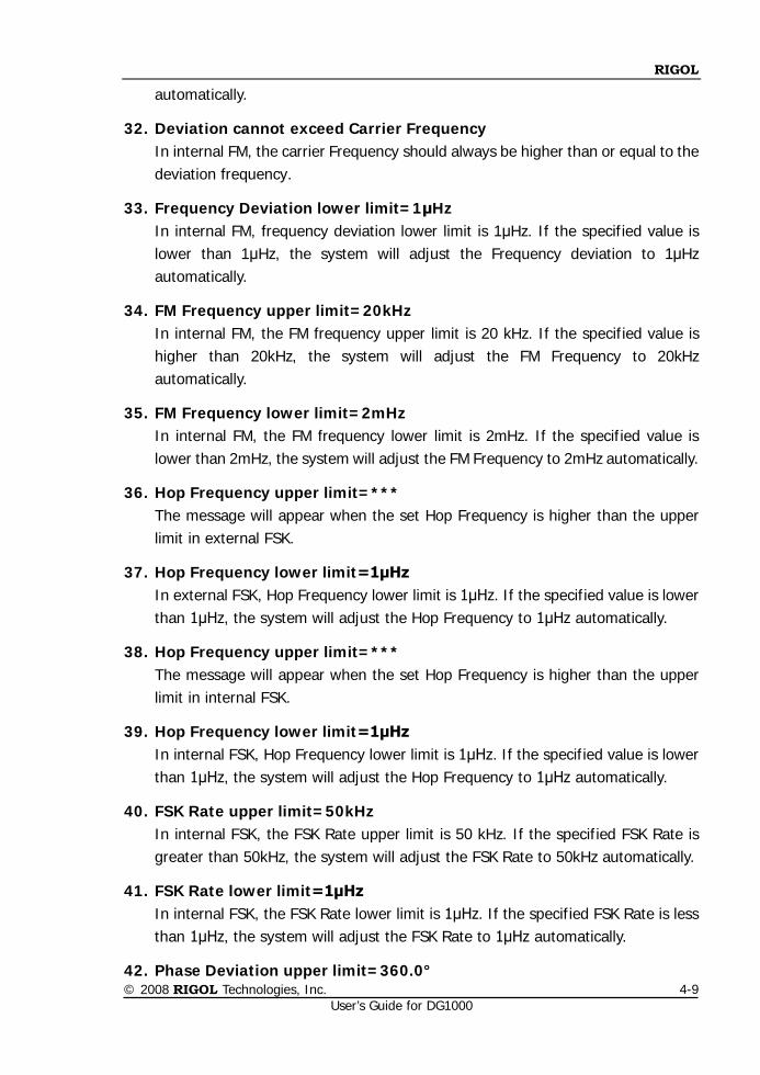
RIGOL
© 2008 RIGOL Technologies, Inc. User’s Guide for DG1000
4-9
automatically.
32. Deviation cannot exceed Carrier Frequency In internal FM, the carrier Frequency should always be higher than or equal to the deviation frequency.
33. Frequency Deviation lower limit=1μHz In internal FM, frequency deviation lower limit is 1μHz. If the specified value is lower than 1μHz, the system will adjust the Frequency deviation to 1μHz automatically.
34. FM Frequency upper limit=20kHz In internal FM, the FM frequency upper limit is 20 kHz. If the specified value is higher than 20kHz, the system will adjust the FM Frequency to 20kHz automatically.
35. FM Frequency lower limit=2mHz In internal FM, the FM frequency lower limit is 2mHz. If the specified value is lower than 2mHz, the system will adjust the FM Frequency to 2mHz automatically.
36. Hop Frequency upper limit=*** The message will appear when the set Hop Frequency is higher than the upper limit in external FSK.
37. Hop Frequency lower limit=1μHz In external FSK, Hop Frequency lower limit is 1μHz. If the specified value is lower than 1μHz, the system will adjust the Hop Frequency to 1μHz automatically.
38. Hop Frequency upper limit=*** The message will appear when the set Hop Frequency is higher than the upper limit in internal FSK.
39. Hop Frequency lower limit=1μHz In internal FSK, Hop Frequency lower limit is 1μHz. If the specified value is lower than 1μHz, the system will adjust the Hop Frequency to 1μHz automatically.
40. FSK Rate upper limit=50kHz In internal FSK, the FSK Rate upper limit is 50 kHz. If the specified FSK Rate is greater than 50kHz, the system will adjust the FSK Rate to 50kHz automatically.
41. FSK Rate lower limit=1μHz In internal FSK, the FSK Rate lower limit is 1μHz. If the specified FSK Rate is less than 1μHz, the system will adjust the FSK Rate to 1μHz automatically.
42. Phase Deviation upper limit=360.0°
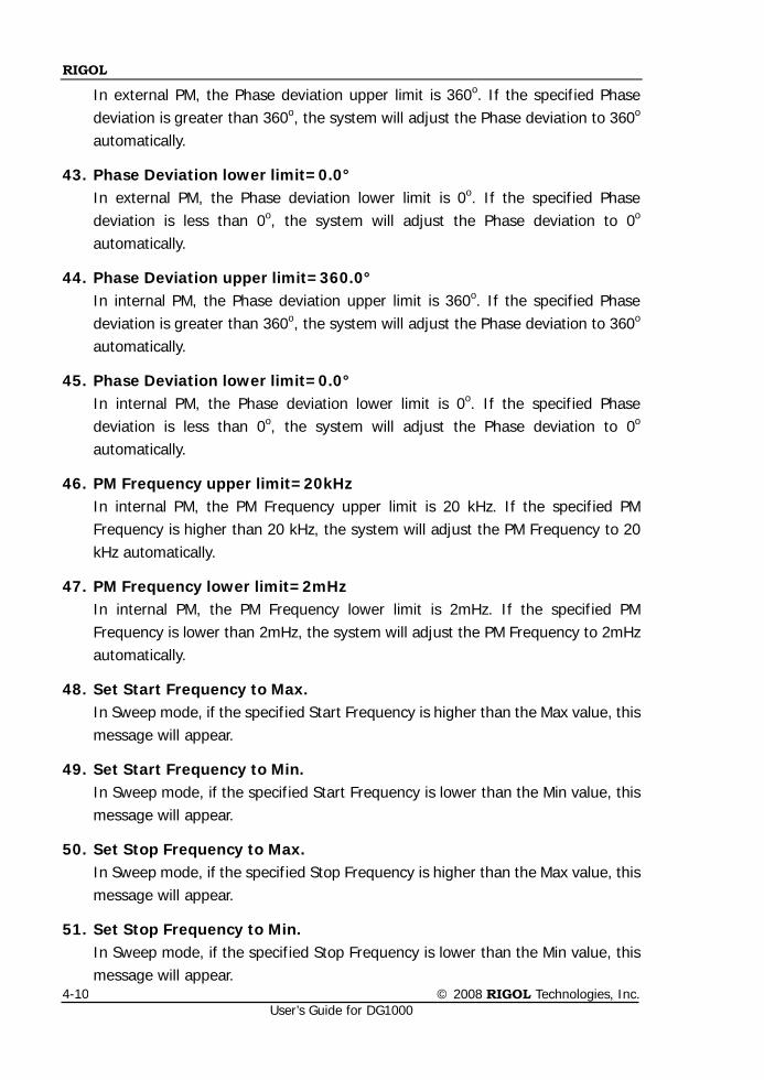
RIGOL
© 2008 RIGOL Technologies, Inc. User’s Guide for DG1000
4-10
In external PM, the Phase deviation upper limit is 360o. If the specified Phase deviation is greater than 360o, the system will adjust the Phase deviation to 360o automatically.
43. Phase Deviation lower limit=0.0° In external PM, the Phase deviation lower limit is 0o. If the specified Phase deviation is less than 0o, the system will adjust the Phase deviation to 0o automatically.
44. Phase Deviation upper limit=360.0° In internal PM, the Phase deviation upper limit is 360o. If the specified Phase deviation is greater than 360o, the system will adjust the Phase deviation to 360o automatically.
45. Phase Deviation lower limit=0.0° In internal PM, the Phase deviation lower limit is 0o. If the specified Phase deviation is less than 0o, the system will adjust the Phase deviation to 0o automatically.
46. PM Frequency upper limit=20kHz In internal PM, the PM Frequency upper limit is 20 kHz. If the specified PM Frequency is higher than 20 kHz, the system will adjust the PM Frequency to 20 kHz automatically.
47. PM Frequency lower limit=2mHz In internal PM, the PM Frequency lower limit is 2mHz. If the specified PM Frequency is lower than 2mHz, the system will adjust the PM Frequency to 2mHz automatically.
48. Set Start Frequency to Max. In Sweep mode, if the specified Start Frequency is higher than the Max value, this message will appear.
49. Set Start Frequency to Min. In Sweep mode, if the specified Start Frequency is lower than the Min value, this message will appear.
50. Set Stop Frequency to Max. In Sweep mode, if the specified Stop Frequency is higher than the Max value, this message will appear.
51. Set Stop Frequency to Min. In Sweep mode, if the specified Stop Frequency is lower than the Min value, this message will appear.
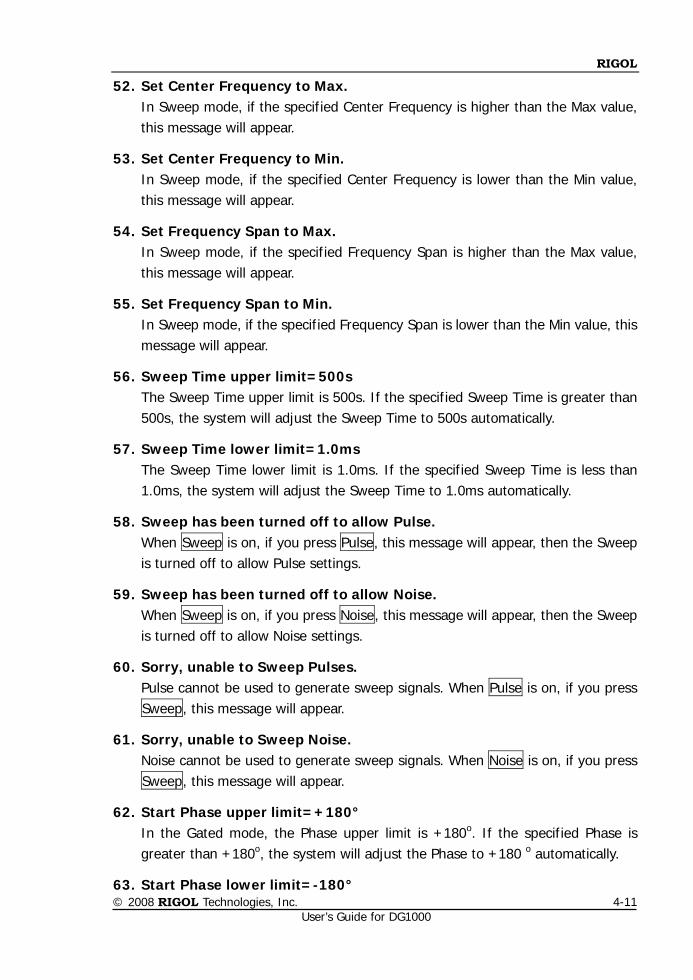
RIGOL
© 2008 RIGOL Technologies, Inc. User’s Guide for DG1000
4-11
52. Set Center Frequency to Max. In Sweep mode, if the specified Center Frequency is higher than the Max value, this message will appear.
53. Set Center Frequency to Min. In Sweep mode, if the specified Center Frequency is lower than the Min value, this message will appear.
54. Set Frequency Span to Max. In Sweep mode, if the specified Frequency Span is higher than the Max value, this message will appear.
55. Set Frequency Span to Min. In Sweep mode, if the specified Frequency Span is lower than the Min value, this message will appear.
56. Sweep Time upper limit=500s The Sweep Time upper limit is 500s. If the specified Sweep Time is greater than 500s, the system will adjust the Sweep Time to 500s automatically.
57. Sweep Time lower limit=1.0ms The Sweep Time lower limit is 1.0ms. If the specified Sweep Time is less than 1.0ms, the system will adjust the Sweep Time to 1.0ms automatically.
58. Sweep has been turned off to allow Pulse. When Sweep is on, if you press Pulse, this message will appear, then the Sweep is turned off to allow Pulse settings.
59. Sweep has been turned off to allow Noise. When Sweep is on, if you press Noise, this message will appear, then the Sweep is turned off to allow Noise settings.
60. Sorry, unable to Sweep Pulses. Pulse cannot be used to generate sweep signals. When Pulse is on, if you press Sweep, this message will appear.
61. Sorry, unable to Sweep Noise. Noise cannot be used to generate sweep signals. When Noise is on, if you press Sweep, this message will appear.
62. Start Phase upper limit=+180° In the Gated mode, the Phase upper limit is +180o. If the specified Phase is greater than +180o, the system will adjust the Phase to +180 o automatically.
63. Start Phase lower limit=-180°
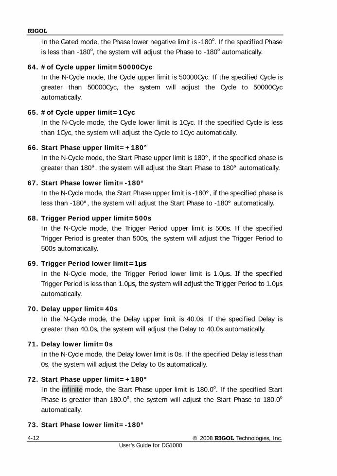
RIGOL
© 2008 RIGOL Technologies, Inc. User’s Guide for DG1000
4-12
In the Gated mode, the Phase lower negative limit is -180o. If the specified Phase is less than -180o, the system will adjust the Phase to -180o automatically.
64. #of Cycle upper limit=50000Cyc In the N-Cycle mode, the Cycle upper limit is 50000Cyc. If the specified Cycle is greater than 50000Cyc, the system will adjust the Cycle to 50000Cyc automatically.
65. #of Cycle upper limit=1Cyc In the N-Cycle mode, the Cycle lower limit is 1Cyc. If the specified Cycle is less than 1Cyc, the system will adjust the Cycle to 1Cyc automatically.
66. Start Phase upper limit=+180° In the N-Cycle mode, the Start Phase upper limit is 180°, if the specified phase is greater than 180°, the system will adjust the Start Phase to 180° automatically.
67. Start Phase lower limit=-180° In the N-Cycle mode, the Start Phase upper limit is -180°, if the specified phase is less than -180°, the system will adjust the Start Phase to -180° automatically.
68. Trigger Period upper limit=500s In the N-Cycle mode, the Trigger Period upper limit is 500s. If the specified Trigger Period is greater than 500s, the system will adjust the Trigger Period to 500s automatically.
69. Trigger Period lower limit=1μs In the N-Cycle mode, the Trigger Period lower limit is 1.0μs. If the specified Trigger Period is less than 1.0μs, the system will adjust the Trigger Period to 1.0μs automatically.
70. Delay upper limit=40s In the N-Cycle mode, the Delay upper limit is 40.0s. If the specified Delay is greater than 40.0s, the system will adjust the Delay to 40.0s automatically.
71. Delay lower limit=0s In the N-Cycle mode, the Delay lower limit is 0s. If the specified Delay is less than 0s, the system will adjust the Delay to 0s automatically.
72. Start Phase upper limit=+180° In the infinite mode, the Start Phase upper limit is 180.0o. If the specified Start Phase is greater than 180.0o, the system will adjust the Start Phase to 180.0o automatically.
73. Start Phase lower limit=-180°
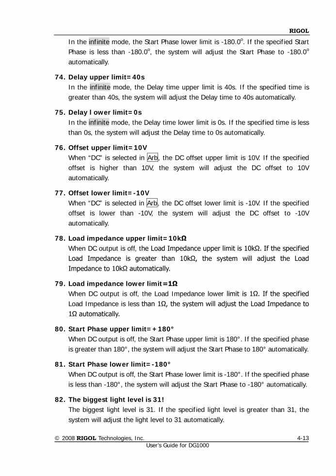
RIGOL
© 2008 RIGOL Technologies, Inc. User’s Guide for DG1000
4-13
In the infinite mode, the Start Phase lower limit is -180.0o. If the specified Start Phase is less than -180.0o, the system will adjust the Start Phase to -180.0o automatically.
74. Delay upper limit=40s In the infinite mode, the Delay time upper limit is 40s. If the specified time is greater than 40s, the system will adjust the Delay time to 40s automatically.
75. Delay l ower limit=0s In the infinite mode, the Delay time lower limit is 0s. If the specified time is less than 0s, the system will adjust the Delay time to 0s automatically.
76. Offset upper limit=10V When “DC” is selected in Arb, the DC offset upper limit is 10V. If the specified offset is higher than 10V, the system will adjust the DC offset to 10V automatically.
77. Offset lower limit=-10V When “DC” is selected in Arb, the DC offset lower limit is -10V. If the specified offset is lower than -10V, the system will adjust the DC offset to -10V automatically.
78. Load impedance upper limit=10kΩ When DC output is off, the Load Impedance upper limit is 10kΩ. If the specified Load Impedance is greater than 10kΩ, the system will adjust the Load Impedance to 10kΩ automatically.
79. Load impedance lower limit=1Ω When DC output is off, the Load Impedance lower limit is 1Ω. If the specified Load Impedance is less than 1Ω, the system will adjust the Load Impedance to 1Ω automatically.
80. Start Phase upper limit=+180° When DC output is off, the Start Phase upper limit is 180°. If the specified phase is greater than 180°, the system will adjust the Start Phase to 180° automatically.
81. Start Phase lower limit=-180° When DC output is off, the Start Phase lower limit is -180°. If the specified phase is less than -180°, the system will adjust the Start Phase to -180° automatically.
82. The biggest light level is 31! The biggest light level is 31. If the specified light level is greater than 31, the system will adjust the light level to 31 automatically.
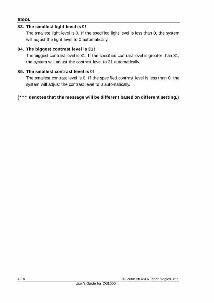
RIGOL
© 2008 RIGOL Technologies, Inc. User’s Guide for DG1000
4-14
83. The smallest light level is 0! The smallest light level is 0. If the specified light level is less than 0, the system will adjust the light level to 0 automatically.
84. The biggest contrast level is 31! The biggest contrast level is 31. If the specified contrast level is greater than 31, the system will adjust the contrast level to 31 automatically.
85. The smallest contrast level is 0! The smallest contrast level is 0. If the specified contrast level is less than 0, the system will adjust the contrast level to 0 automatically.
(*** denotes that the message will be different based on different setting.)
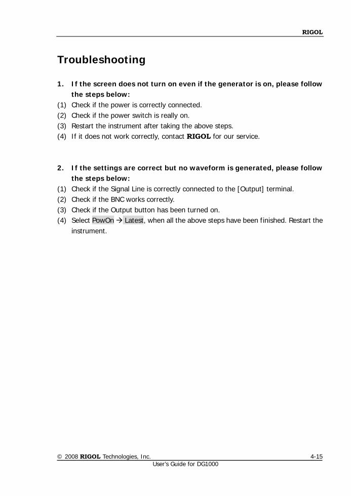
RIGOL
© 2008 RIGOL Technologies, Inc. User’s Guide for DG1000
4-15
Troubleshooting
1. If the screen does not turn on even if the generator is on, please follow the steps below:
(1) Check if the power is correctly connected. (2) Check if the power switch is really on. (3) Restart the instrument after taking the above steps. (4) If it does not work correctly, contact RIGOL for our service. 2. If the settings are correct but no waveform is generated, please follow
the steps below: (1) Check if the Signal Line is correctly connected to the [Output] terminal. (2) Check if the BNC works correctly. (3) Check if the Output button has been turned on. (4) Select PowOn Latest, when all the above steps have been finished. Restart the
instrument.

RIGOL
© 2008 RIGOL Technologies, Inc.
User’s Guide for DG1000 5-1
Chapter 5 Specifications
All the specifications apply to the DG1000 series Dual-Channel Function/ Arbitrary Waveform Generator unless specified statement. To meet these specifications, two conditions must be satisfied first: The instrument must have operated continuously for more than 30 minutes
within the specified operating temperature (18°C ~ 28°C). Variation of the operating temperature should be within 5 oC.
All specifications are guaranteed unless noted “typical”.
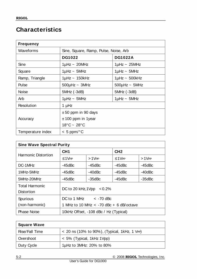
RIGOL
© 2008 RIGOL Technologies, Inc. User’s Guide for DG1000
5-2
Characteristics
Frequency
Waveforms Sine, Square, Ramp, Pulse, Noise, Arb
DG1022 DG1022A
Sine 1µHz ~ 20MHz 1µHz ~ 25MHz
Square 1µHz ~ 5MHz 1µHz ~ 5MHz
Ramp, Triangle 1µHz ~ 150kHz 1µHz ~ 500kHz
Pulse 500µHz ~ 3MHz 500µHz ~ 5MHz
Noise 5MHz (-3dB) 5MHz (-3dB)
Arb 1µHz ~ 5MHz 1µHz ~ 5MHz
Resolution 1 µHz
Accuracy
±50 ppm in 90 days
±100 ppm in 1year
18°C ~ 28°C
Temperature index < 5 ppm/°C
Sine Wave Spectral Purity
Harmonic Distortion CH1 CH2
≤1VPP >1VPP ≤1VPP >1VPP
DC-1MHz -45dBc -45dBc -45dBc -45dBc
1MHz-5MHz -45dBc -40dBc -45dBc -40dBc
5MHz-20MHz -45dBc -35dBc -45dBc -35dBc
Total Harmonic Distortion
DC to 20 kHz,1Vpp <0.2%
Spurious (non-harmonic)
DC to 1 MHz < -70 dBc
1 MHz to 10 MHz < -70 dBc + 6 dB/octave
Phase Noise 10kHz Offset, -108 dBc / Hz (Typical)
Square Wave
Rise/Fall Time < 20 ns (10% to 90%), (Typical, 1kHz, 1 VPP)
Overshoot < 5% (Typical, 1kHz 1Vpp)
Duty Cycle 1µHz to 3MHz: 20% to 80%
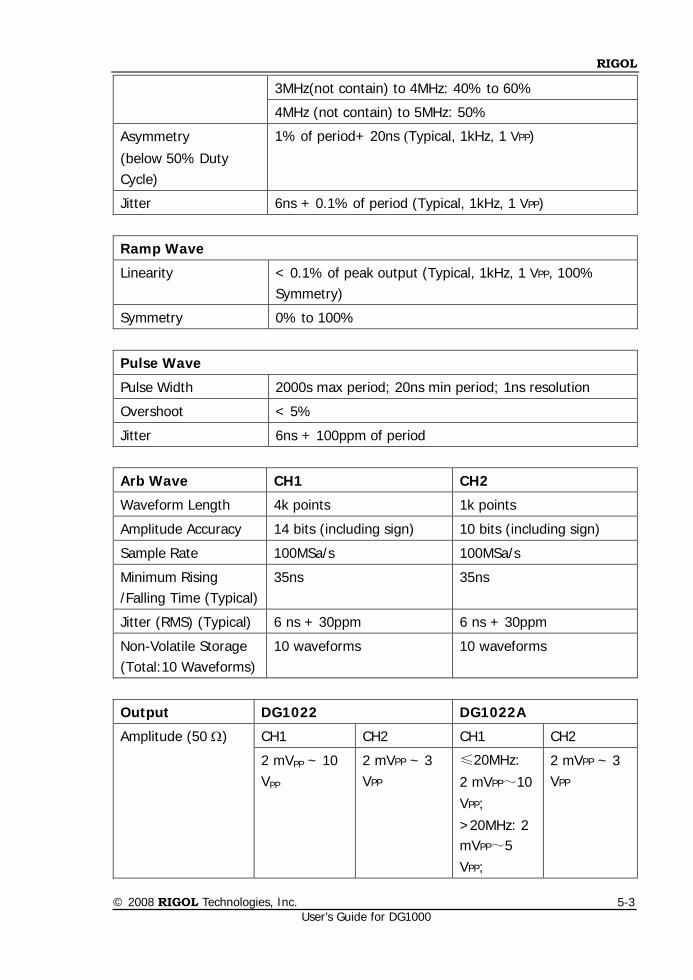
RIGOL
© 2008 RIGOL Technologies, Inc.
User’s Guide for DG1000 5-3
3MHz(not contain) to 4MHz: 40% to 60%
4MHz (not contain) to 5MHz: 50%
Asymmetry
(below 50% Duty Cycle)
1% of period+ 20ns (Typical, 1kHz, 1 VPP)
Jitter 6ns + 0.1% of period (Typical, 1kHz, 1 VPP)
Ramp Wave
Linearity < 0.1% of peak output (Typical, 1kHz, 1 VPP, 100% Symmetry)
Symmetry 0% to 100%
Pulse Wave
Pulse Width 2000s max period; 20ns min period; 1ns resolution
Overshoot < 5%
Jitter 6ns + 100ppm of period
Arb Wave CH1 CH2
Waveform Length 4k points 1k points
Amplitude Accuracy 14 bits (including sign) 10 bits (including sign)
Sample Rate 100MSa/s 100MSa/s
Minimum Rising /Falling Time (Typical)
35ns 35ns
Jitter (RMS) (Typical) 6 ns + 30ppm 6 ns + 30ppm
Non-Volatile Storage (Total:10 Waveforms)
10 waveforms 10 waveforms
Output DG1022 DG1022A
Amplitude (50 Ω) CH1 CH2 CH1 CH2
2 mVPP ~ 10 VPP
2 mVPP ~ 3 VPP
≤20MHz:
2 mVPP~10 VPP;
>20MHz: 2 mVPP~5 VPP;
2 mVPP ~ 3 VPP
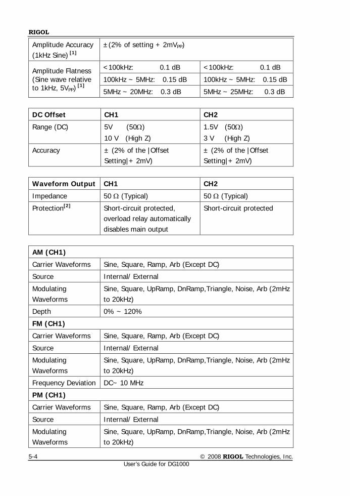
RIGOL
© 2008 RIGOL Technologies, Inc. User’s Guide for DG1000
5-4
Amplitude Accuracy (1kHz Sine) [1]
±(2% of setting + 2mVPP)
Amplitude Flatness (Sine wave relative to 1kHz, 5VPP)
[1]
<100kHz: 0.1 dB <100kHz: 0.1 dB
100kHz ~ 5MHz: 0.15 dB 100kHz ~ 5MHz: 0.15 dB
5MHz ~ 20MHz: 0.3 dB 5MHz ~ 25MHz: 0.3 dB
DC Offset CH1 CH2
Range (DC) 5V (50Ω)
10 V (High Z)
1.5V (50Ω)
3 V (High Z)
Accuracy ± (2% of the |Offset Setting|+ 2mV)
± (2% of the |Offset Setting|+ 2mV)
Waveform Output CH1 CH2
Impedance 50 Ω (Typical) 50 Ω (Typical)
Protection[2] Short-circuit protected, overload relay automatically disables main output
Short-circuit protected
AM (CH1)
Carrier Waveforms Sine, Square, Ramp, Arb (Except DC)
Source Internal/ External
Modulating Waveforms
Sine, Square, UpRamp, DnRamp,Triangle, Noise, Arb (2mHz to 20kHz)
Depth 0% ~ 120%
FM (CH1)
Carrier Waveforms Sine, Square, Ramp, Arb (Except DC)
Source Internal/ External
Modulating Waveforms
Sine, Square, UpRamp, DnRamp,Triangle, Noise, Arb (2mHz to 20kHz)
Frequency Deviation DC~ 10 MHz
PM (CH1)
Carrier Waveforms Sine, Square, Ramp, Arb (Except DC)
Source Internal/ External
Modulating Waveforms
Sine, Square, UpRamp, DnRamp,Triangle, Noise, Arb (2mHz to 20kHz)
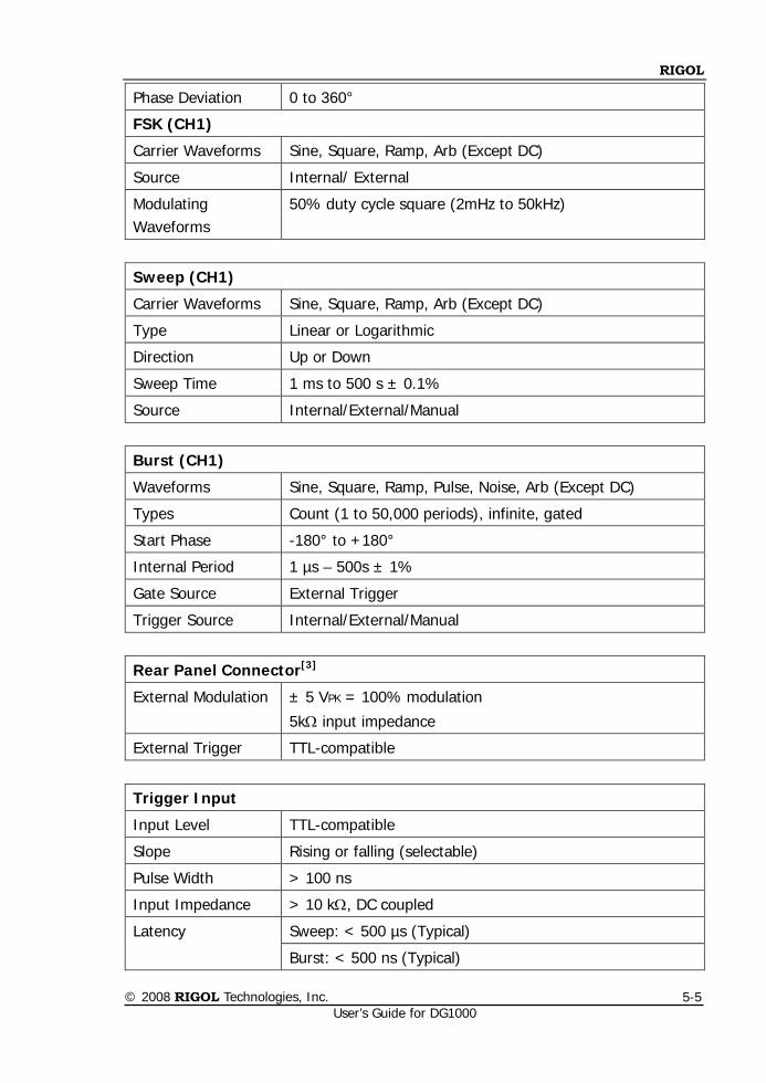
RIGOL
© 2008 RIGOL Technologies, Inc.
User’s Guide for DG1000 5-5
Phase Deviation 0 to 360°
FSK (CH1)
Carrier Waveforms Sine, Square, Ramp, Arb (Except DC)
Source Internal/ External
Modulating Waveforms
50% duty cycle square (2mHz to 50kHz)
Sweep (CH1)
Carrier Waveforms Sine, Square, Ramp, Arb (Except DC)
Type Linear or Logarithmic
Direction Up or Down
Sweep Time 1 ms to 500 s ± 0.1%
Source Internal/External/Manual
Burst (CH1)
Waveforms Sine, Square, Ramp, Pulse, Noise, Arb (Except DC)
Types Count (1 to 50,000 periods), infinite, gated
Start Phase -180° to +180°
Internal Period 1 µs – 500s ± 1%
Gate Source External Trigger
Trigger Source Internal/External/Manual
Rear Panel Connector[3]
External Modulation ± 5 VPK = 100% modulation
5kΩ input impedance
External Trigger TTL-compatible
Trigger Input
Input Level TTL-compatible
Slope Rising or falling (selectable)
Pulse Width > 100 ns
Input Impedance > 10 kΩ, DC coupled
Latency Sweep: < 500 µs (Typical)
Burst: < 500 ns (Typical)
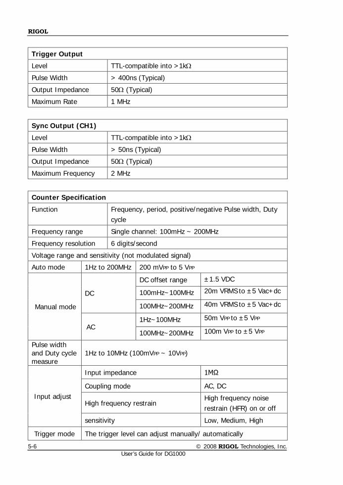
RIGOL
© 2008 RIGOL Technologies, Inc. User’s Guide for DG1000
5-6
Trigger Output
Level TTL-compatible into >1kΩ
Pulse Width > 400ns (Typical)
Output Impedance 50Ω (Typical)
Maximum Rate 1 MHz
Sync Output (CH1)
Level TTL-compatible into >1kΩ
Pulse Width > 50ns (Typical)
Output Impedance 50Ω (Typical)
Maximum Frequency 2 MHz
Counter Specification
Function Frequency, period, positive/negative Pulse width, Duty cycle
Frequency range Single channel: 100mHz ~ 200MHz
Frequency resolution 6 digits/second
Voltage range and sensitivity (not modulated signal)
Auto mode 1Hz to 200MHz 200 mVPP to 5 VPP
Manual mode
DC
DC offset range ±1.5 VDC
100mHz~100MHz 20m VRMS to ±5 Vac+dc
100MHz~200MHz 40m VRMS to ±5 Vac+dc
AC 1Hz~100MHz 50m VPP to ±5 VPP
100MHz~200MHz 100m VPP to ±5 VPP
Pulse width and Duty cycle measure
1Hz to 10MHz (100mVPP ~ 10VPP)
Input adjust
Input impedance 1MΩ
Coupling mode AC, DC
High frequency restrain High frequency noise restrain (HFR) on or off
sensitivity Low, Medium, High
Trigger mode The trigger level can adjust manually/ automatically
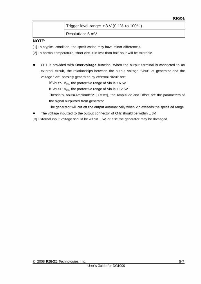
RIGOL
© 2008 RIGOL Technologies, Inc.
User’s Guide for DG1000 5-7
Trigger level range: ±3 V (0.1% to 100%)
Resolution: 6 mV
NOTE: [1] In atypical condition, the specification may have minor differences.
[2] In normal temperature, short circuit in less than half hour will be tolerable.
CH1 is provided with Overvoltage function. When the output terminal is connected to an
external circuit, the relationships between the output voltage “Vout” of generator and the
voltage “Vin” possibly generated by external circuit are:
If Vout≤1VDC, the protective range of Vin is ±6.5V
If Vout>1VDC, the protective range of Vin is ±12.5V
Thereinto, Vout=Amplitude/2+|Offset|, the Amplitude and Offset are the parameters of
the signal outputted from generator.
The generator will cut off the output automatically when Vin exceeds the specified range.
The voltage inputted to the output connector of CH2 should be within ±3V.
[3] External input voltage should be within ±5V, or else the generator may be damaged.
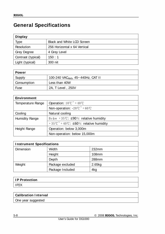
RIGOL
© 2008 RIGOL Technologies, Inc. User’s Guide for DG1000
5-8
General Specifications
Display Type Black and White LCD Screen Resolution 256 Horizontal x 64 Vertical Grey Degree 4 Grey Level Contrast (typical) 150 : 1 Light (typical) 300 nit
Power Supply 100-240 VACRMS, 45~440Hz, CAT II Consumption Less than 40W Fuse 2A, T Level , 250V
Environment Temperature Range Operation: 10~ + 40
Non-operation: -20~ + 60 Cooling Natural cooling Humidity Range Below + 35: ≤90% relative humidity
+ 35~ + 40: ≤60% relative humidity
Height Range Operation: below 3,000m Non-operation: below 15,000m
Instrument Specifications Dimension Width 232mm
Height 108mm Depth 288mm
Weight Package excluded 2.65kg Package Included 4kg
IP Protection IP2X
Calibration Interval One year suggested
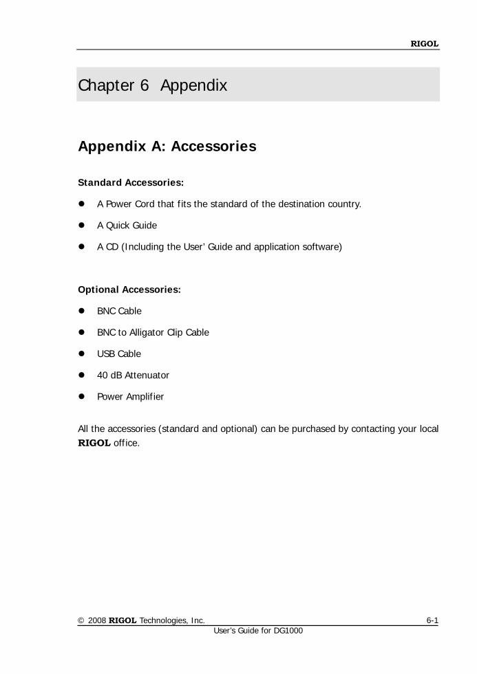
RIGOL
© 2008 RIGOL Technologies, Inc. User’s Guide for DG1000
6-1
Chapter 6 Appendix
Appendix A: Accessories
Standard Accessories:
A Power Cord that fits the standard of the destination country.
A Quick Guide
A CD (Including the User’ Guide and application software)
Optional Accessories:
BNC Cable
BNC to Alligator Clip Cable
USB Cable
40 dB Attenuator
Power Amplifier
All the accessories (standard and optional) can be purchased by contacting your local RIGOL office.
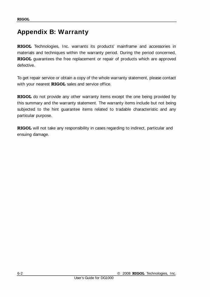
RIGOL
© 2008 RIGOL Technologies, Inc. User’s Guide for DG1000
6-2
Appendix B: Warranty
RIGOL Technologies, Inc. warrants its products’ mainframe and accessories in materials and techniques within the warranty period. During the period concerned, RIGOL guarantees the free replacement or repair of products which are approved defective. To get repair service or obtain a copy of the whole warranty statement, please contact with your nearest RIGOL sales and service office. RIGOL do not provide any other warranty items except the one being provided by this summary and the warranty statement. The warranty items include but not being subjected to the hint guarantee items related to tradable characteristic and any particular purpose. RIGOL will not take any responsibility in cases regarding to indirect, particular and ensuing damage.
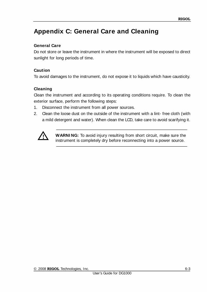
RIGOL
© 2008 RIGOL Technologies, Inc. User’s Guide for DG1000
6-3
Appendix C: General Care and Cleaning
General Care Do not store or leave the instrument in where the instrument will be exposed to direct sunlight for long periods of time. Caution To avoid damages to the instrument, do not expose it to liquids which have causticity. Cleaning Clean the instrument and according to its operating conditions require. To clean the exterior surface, perform the following steps: 1. Disconnect the instrument from all power sources. 2. Clean the loose dust on the outside of the instrument with a lint- free cloth (with
a mild detergent and water). When clean the LCD, take care to avoid scarifying it.
WARNING: To avoid injury resulting from short circuit, make sure the instrument is completely dry before reconnecting into a power source.
!


