Risk Based Inspection (RBI) - A Transparent Process?
Presented by: Cheryl Frolish
MACAW Engineering Ltd
Co-Authors: Ian Diggory, Richard Elsdon, Krista McGowanMACAW Engineering Ltd
Richard JonesTalisman Energy (UK) Limited 1
• Introduction
• Topsides & Pipelines
• RBI & Operators Integrity Management Strategy
• RBI Concept & Schemes
• Talisman RBI Process – MACAW Experience
• Conclusions
• Questions
2
3
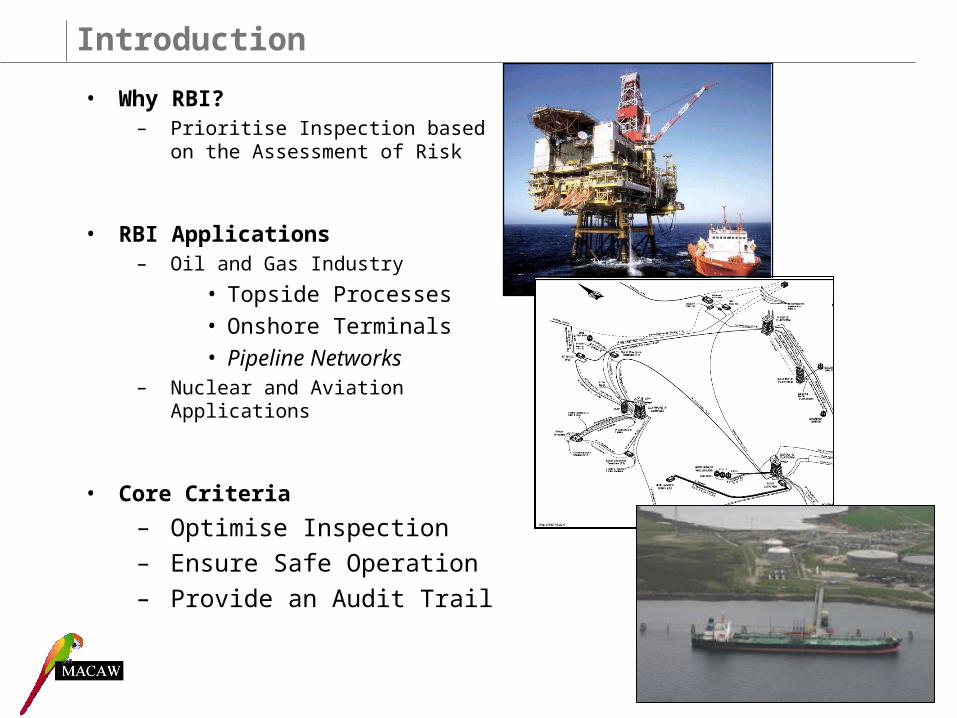
Introduction
• Why RBI?– Prioritise Inspection based on the
Assessment of Risk
• RBI Applications– Oil and Gas Industry
• Topside Processes
• Onshore Terminals
• Pipeline Networks– Nuclear and Aviation
Applications
• Core Criteria
– Optimise Inspection– Ensure Safe Operation– Provide an Audit Trail
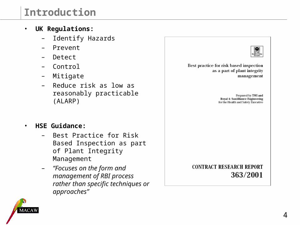
Introduction
• UK Regulations: – Identify Hazards– Prevent– Detect– Control– Mitigate– Reduce risk as low as
reasonably practicable (ALARP)
• HSE Guidance:– Best Practice for Risk Based
Inspection as part of Plant Integrity Management
– “Focuses on the form and management of RBI process rather than specific techniques or approaches”
4
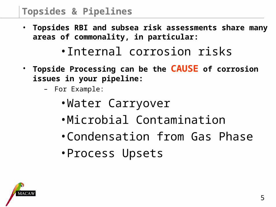
Topsides & Pipelines
• Topsides RBI and subsea risk assessments share many areas of commonality, in particular:
• Internal corrosion risks• Topside Processing can be the CAUSE of corrosion issues in
your pipeline:– For Example:
• Water Carryover
• Microbial Contamination
• Condensation from Gas Phase
• Process Upsets
5
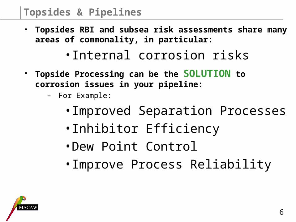
Topsides & Pipelines
• Topsides RBI and subsea risk assessments share many areas of commonality, in particular:
• Internal corrosion risks• Topside Processing can be the SOLUTION to corrosion issues
in your pipeline:– For Example:
• Improved Separation Processes
• Inhibitor Efficiency
• Dew Point Control
• Improve Process Reliability
6
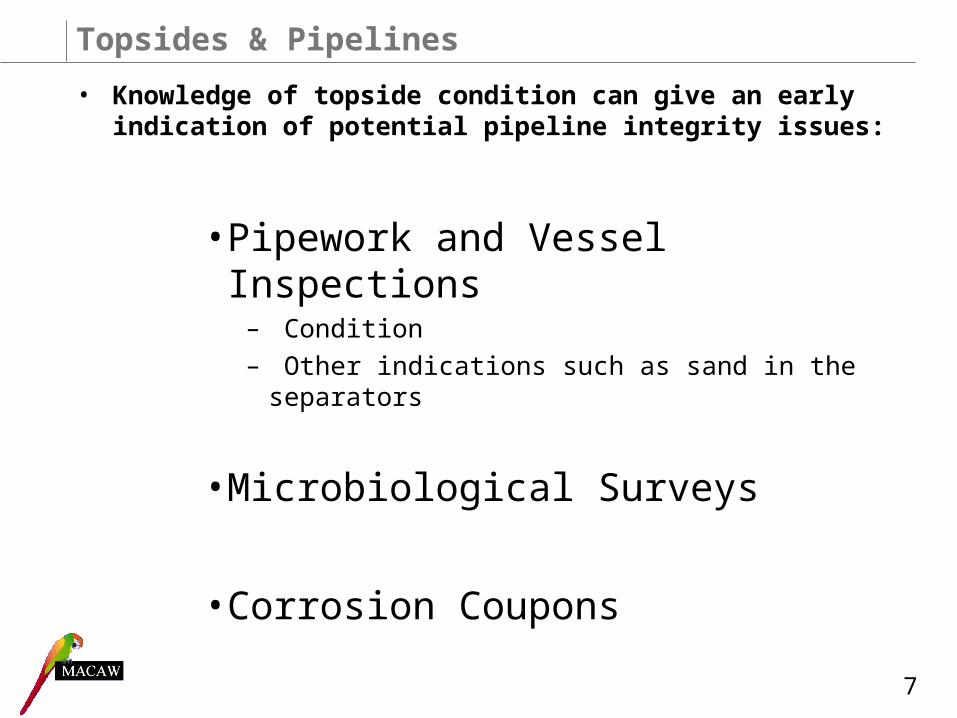
Topsides & Pipelines
• Knowledge of topside condition can give an early indication of potential pipeline integrity issues:
• Pipework and Vessel Inspections– Condition– Other indications such as sand in the separators
• Microbiological Surveys
• Corrosion Coupons
7
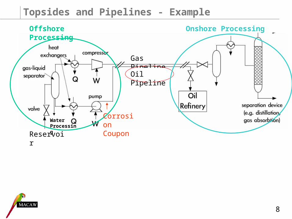
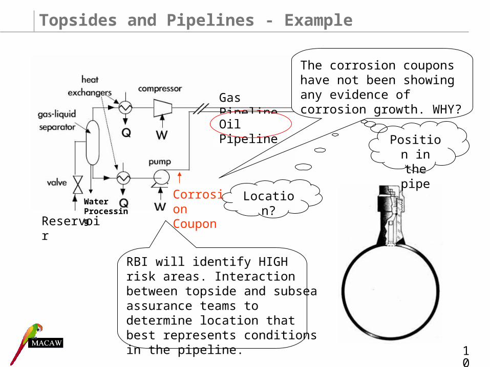
Topsides and Pipelines - Example
Reservoir
Gas Pipeline
Oil Pipeline
Offshore Processing Onshore Processing
Corrosion Coupon
Water Processing
8

Topsides and Pipelines - Example
Corrosion Coupon
Possible Causes:
• Poor separation allowing for water carryover
• Inhibitor partitioning time
• Process Upsets
• MIC
0
45
90
135
180
225
270
315
360
0 10 20 30 40 50 60
Distance - Km
Ori
enta
tio
n -
deg
rees
9
Topsides and Pipelines - Example
Reservoir
Gas Pipeline
Oil Pipeline
Corrosion Coupon
RBI will identify HIGH risk areas. Interaction between topside and subsea assurance teams to determine location that best represents conditions in the pipeline.
The corrosion coupons have not been showing any evidence of corrosion growth. WHY?
Position in the pipe
Location?Water Processing
10
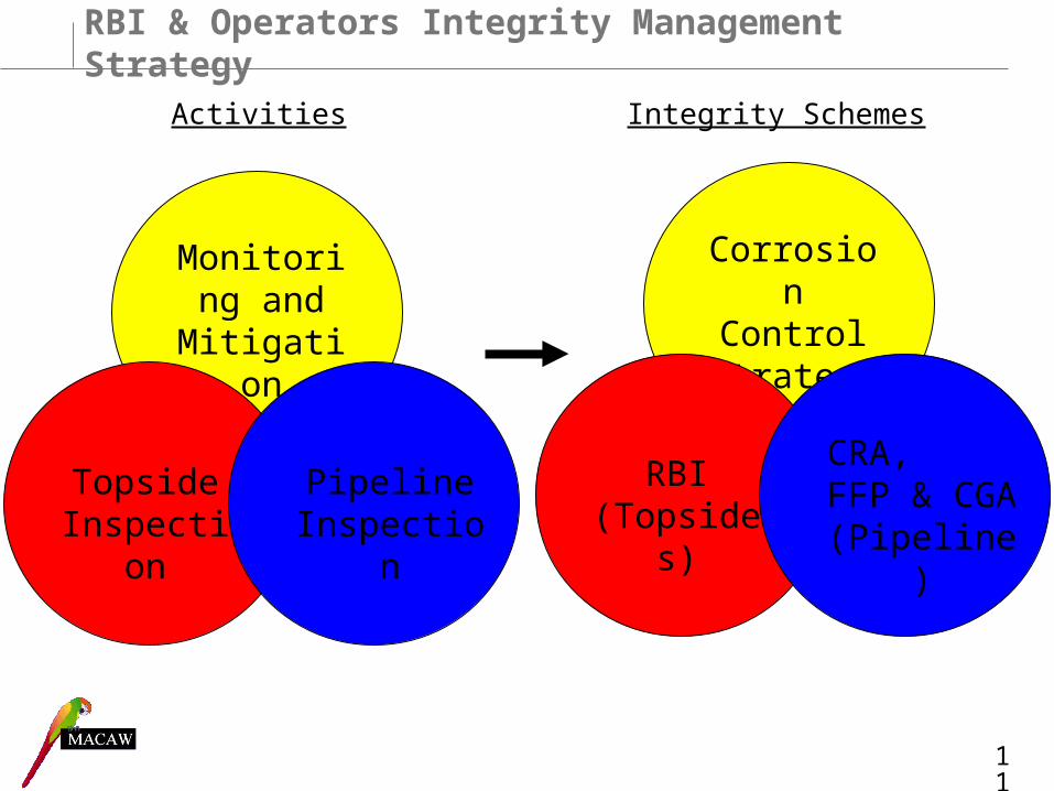
RBI & Operators Integrity Management Strategy
Monitoring and
Mitigation
Topside Inspection
Pipeline Inspection
Corrosion Control Strategy
RBI (Topsides)
CRA, FFP & CGA (Pipeline)
11
Activities Integrity Schemes

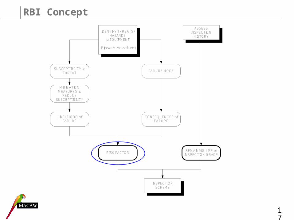
RBI Concept
12
IDENTIFY THREATS/HAZARDS
to EQUIPMENT
(Pipework, Vessels etc)
SUSCEPTIBILITY to THREAT
MITIGATION MEASURES to
REDUCE SUSCEPTIBILITY
LIKELIHOOD of FAILURE
FAILURE MODE
CONSEQUENCES of FAILURE
ASSESS INSPECTION
HISTORY
REMAINING LIFE or INSPECTION GRADE
IDENTIFY THREATS/HAZARDS
to EQUIPMENT
(Pipework, Vessels etc)
SUSCEPTIBILITY to THREAT
MITIGATION MEASURES to
REDUCE SUSCEPTIBILITY
LIKELIHOOD of FAILURE
FAILURE MODE
CONSEQUENCES of FAILURE
ASSESS INSPECTION
HISTORY
REMAINING LIFE or INSPECTION GRADE
RISK FACTOR
INSPECTION SCHEME

Internal Threats
• Internal Corrosion– Sweet Corrosion
– Sour Corrosion / Cracking Mechanisms
– MIC (Microbiologically Induced Corrosion)
– Oxygen Corrosion
– Other potential mechanisms?
• E.g. Acetic Acid weld degradation
Ref: MACAW Defect Atlas, Dr. Colin Argent 13

External Threats
• External Corrosion
– Atmospheric Corrosion
– CUI (Corrosion Under Insulation)
– Chloride pitting of stainless steels
– Galvanic corrosion
– Other potential mechanisms?
Ref: HSE Offshore External Corrosion Guide
14
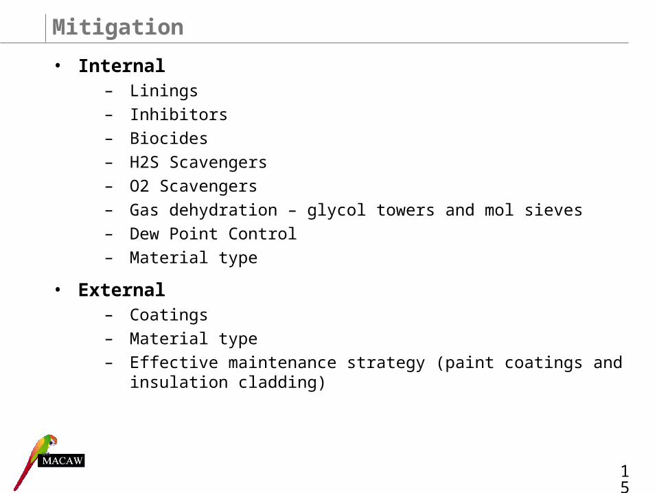
Mitigation
• Internal– Linings
– Inhibitors
– Biocides
– H2S Scavengers
– O2 Scavengers
– Gas dehydration – glycol towers and mol sieves
– Dew Point Control
– Material type
• External– Coatings
– Material type
– Effective maintenance strategy (paint coatings and insulation cladding)
15
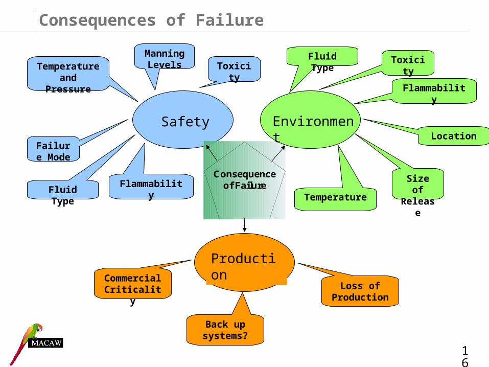
Consequences of Failure
Consequence of Failure
Safety Environment
Production
Fluid Type
Failure Mode
Manning LevelsTemperature
and Pressure
Flammability
Toxicity
Size of Release
Fluid Type
Location
Temperature
Flammability
Toxicity
Commercial Criticality
Back up systems?
Loss of Production
16
RBI Concept
17
IDENTIFY THREATS/HAZARDS
to EQUIPMENT
(Pipework, Vessels etc)
SUSCEPTIBILITY to THREAT
MITIGATION MEASURES to
REDUCE SUSCEPTIBILITY
LIKELIHOOD of FAILURE
FAILURE MODE
CONSEQUENCES of FAILURE
ASSESS INSPECTION
HISTORY
REMAINING LIFE or INSPECTION GRADE
IDENTIFY THREATS/HAZARDS
to EQUIPMENT
(Pipework, Vessels etc)
SUSCEPTIBILITY to THREAT
MITIGATION MEASURES to
REDUCE SUSCEPTIBILITY
LIKELIHOOD of FAILURE
FAILURE MODE
CONSEQUENCES of FAILURE
ASSESS INSPECTION
HISTORY
REMAINING LIFE or INSPECTION GRADE
RISK FACTOR
INSPECTION SCHEME

Inspection History
Inspection History
Remaining Life
Inspection Grading
API RP 570 & 510
IP 12 &13 Model Code of Safe Practice
Calculate time to failure based on wall thickness measurements.
Maximum inspection interval = ½ remaining service life
Effectiveness and results of inspections are graded. IP
guidelines set out recommended maximum
intervals based on inspection grade
Quantitative
Qualitative
18

Outcome of an RBI?
What? How?
When?
Result of an RBI
Where?
Types of damage expected
Inspection Frequency
Appropriate Inspection Technique
Hotspot locations
19

RBI Schemes
• In 2002 HSE funded a study to compare several RBI schemes– Quantitative vs Qualitative– ‘Black box’ approach– Varying levels of detail
• HSE study identified the need for: – A TRANSPARENT process– A balance between quantitative and qualitative methods– A balance between theory, inspection and engineering judgement
Ref: Risk Based Inspection – A Case Study Evaluation of Onshore Process Plant, W Geary, 2002. 20
Talisman Assets
• North Sea Operator– 11 Platforms
– 1 FPSO
– 2 Onshore Terminals
– Network of over 3000 km of subsea pipelines
• Ageing assets, near or past design life
• Previous owners and inspection companies
• Incomplete data set
• Historical data often stored in hard copy only
• Some existing RBI schemes but varied in type and complexity
• A unified approach was required
21
Talisman RBI Scheme
• Initial Approach
– Talisman had adopted an RBI program
– Based on API half-remaining life approach
– MACAW’s initial role to populate and run this program
• Problem
- Information was limited or just not available
- Program required complete data set to operate successfully
• A common feature of quantitative models- Gaps in inspection history and lack of confidence in results meant that
API approach was not appropriate
22

Talisman RBI Scheme
• MACAW and Talisman collaborated in development of a more robust scheme
– MACAW applied the concept of ‘transparency’ to Talisman RBI scheme
– Moved away from API approach to IP grading method– Top down approach, prioritised safety critical systems
23
Talisman Assets
• Scale of the project:
• 11 platforms, 1 FPSO and 2 onshore terminals– Typical platform:
• 350 vessels (inc. heat exchangers, filters and air accumulators)
• 3000 items of pipework (grouped into ~120 streams)
– For all of Talisman’s assets, this equates to approximately:
• 2500 Vessel RBIs
• 1700 Stream RBIs– The project was split into three phases
• Phase 1 - Safety Critical Systems
• Phases 2 & 3 – Less Critical Systems
24
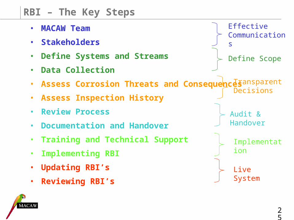
RBI – The Key Steps
• MACAW Team
• Stakeholders
• Define Systems and Streams
• Data Collection
• Assess Corrosion Threats and Consequences
• Assess Inspection History
• Review Process
• Documentation and Handover
• Training and Technical Support
• Implementing RBI
• Updating RBI’s
• Reviewing RBI’s
Effective Communications
Implementation
Live System
25
Define Scope
Transparent Decisions
Audit & Handover
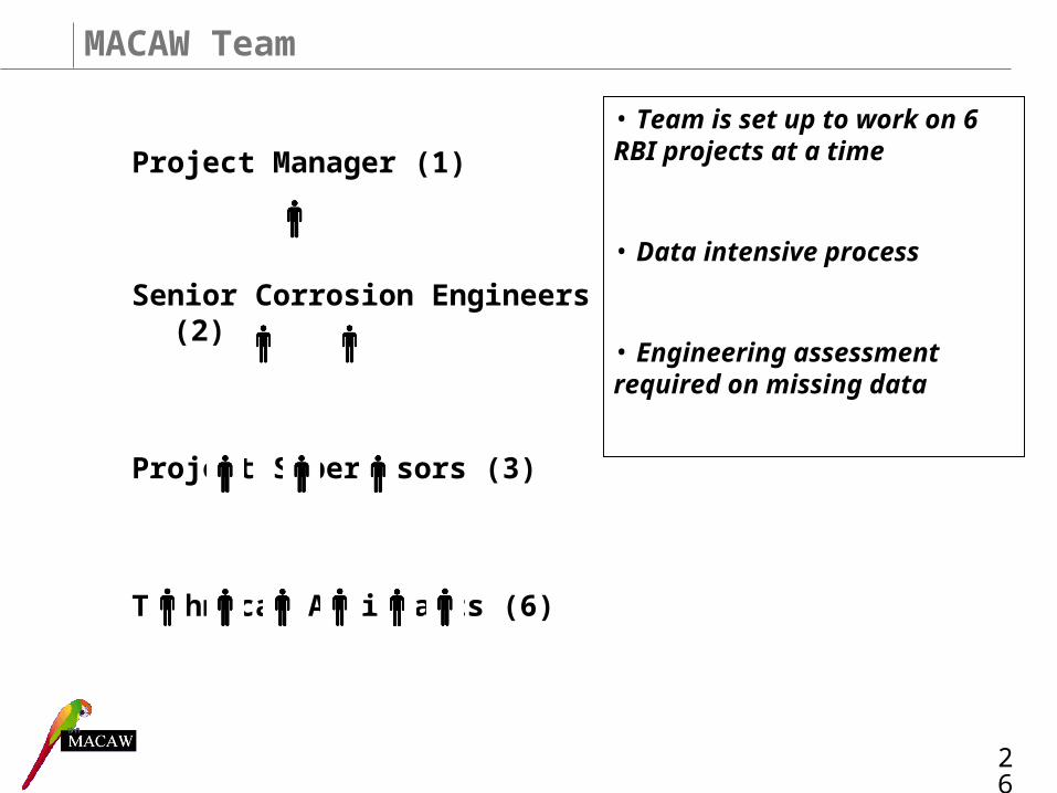
Project Manager (1)
Senior Corrosion Engineers (2)
Project Supervisors (3)
Technical Assistants (6)
MACAW Team
26
• Team is set up to work on 6 RBI projects at a time
• Data intensive process
• Engineering assessment required on missing data

Stakeholders
• Talisman– Assurance Engineer
– Focal Point Engineer
– Process Engineer
– Chemist
– Offshore Inspection Engineer
• Inspection Company– Inspection Engineer
– Corrosion Engineer
27

Systems and Streams
• Systems are defined by their fluid and function, e.g.– Produced Oil & Oil Export
– Gas Compression and Export
– Fuel Gas
• Systems determine equipment to be assessed, such as: – Separation vessels
– Heat exchangers
– Streams
• Streams are used to define sections of pipework operating under similar parameters, such as:
– Pressure
– Temperature
– Material
– Fluid composition
– Added chemicals (e.g. Corrosion Inhibitor injection)
28
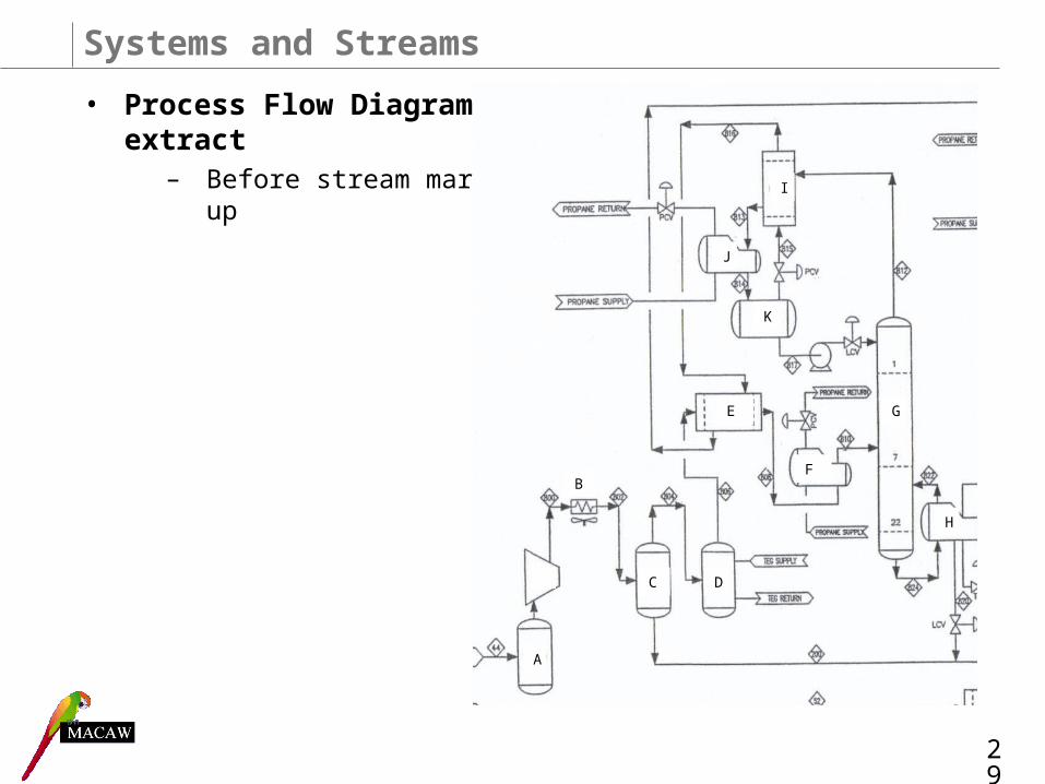
Systems and Streams
• Process Flow Diagram extract
– Before stream mark up
A
B
C D
E
F
G
H
I
J
K
29
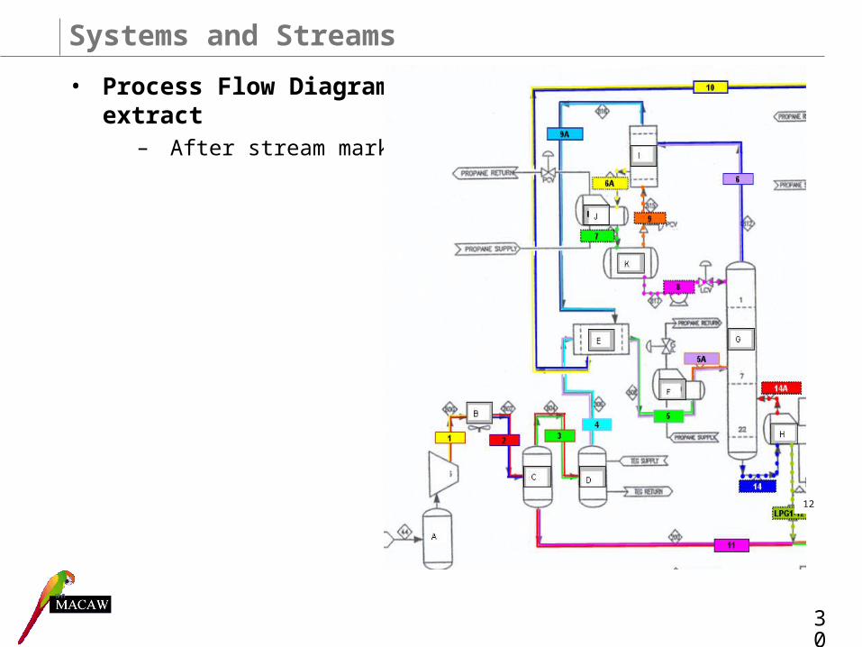
Systems and Streams
• Process Flow Diagram extract
– After stream mark up
12
30
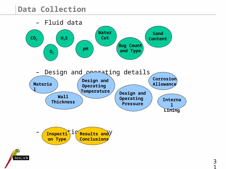
Data Collection
– Fluid data
– Design and operating details
– Inspection history
CO2 H2S
pH
Water Cut
Material
Wall Thickness
Design and Operating
Temperature Design and Operating Pressure
Corrosion Allowance
Internal Lining
Bug Count and TypeO2
Sand Content
Inspection Type
Results and Conclusions
31
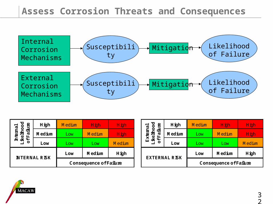
Assess Corrosion Threats and Consequences
Internal Corrosion Mechanisms
Susceptibility Mitigation Likelihood of Failure
External Corrosion Mechanisms
Susceptibility Mitigation Likelihood of Failure
High Medium High High
Medium Low Medium High
Low Low Low Medium
Low Medium High
Inte
rnal
L
ikel
iho
od
o
f F
ailu
re
INTERNAL RISKConsequence of Failure
High Medium High High
Medium Low Medium High
Low Low Low Medium
Low Medium High
Consequence of Failure
Ext
ern
al
Lik
elih
oo
d
of
Fai
lure
EXTERNAL RISK
32
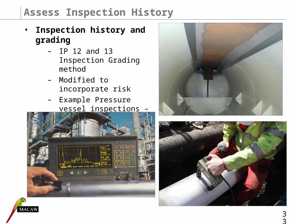
Assess Inspection History
• Inspection history and grading
– IP 12 and 13 Inspection Grading method
– Modified to incorporate risk
– Example Pressure vessel inspections – next slide
33

Assess Inspection History
Equipment Grade 0 Grade 1 Grade 2 Grade 3
Process Pressure vessels and heat exchangers
36 48 84 144
Internal Inspection Intervals for Vessels and Heat Exchangers (Months)
Internal Risk
Grade 0 Grade 1 Grade 2 Grade 3
High 24 36 72 84
Medium 36 48 84 144
Low 48 72 144 144
IP recommended maximum interval
RBI recommended maximum interval
NB: Hydrocarbon Systems will always fall into High and Medium Risk Categories due to the consequence of failure associated with these systems 34
Review Process
• Staged Review Process
– Level 1: Peer Review of each system
– Level 2: Integrity Review covering all systems within each phase
– Representatives required from the following areas:• Assurance• Inspection • Process Engineering• Production Chemist• Operations• Site personnel• Safety and Environment
35
Documentation and Handover
• Documentation of– Assumptions– Issues– Key decisions
• Marked up PFD’s and P&ID’s
• PFD’s hyperlinked to RBI’s
• References for Data Sources
• RBI’s in spreadsheet format
• Change logging
• Live summary sheet
36
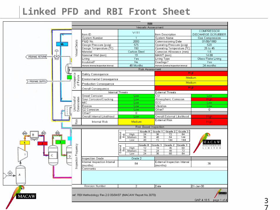
Linked PFD and RBI Front Sheet
37
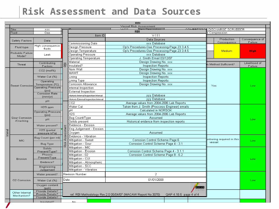
Risk Assessment and Data Sources
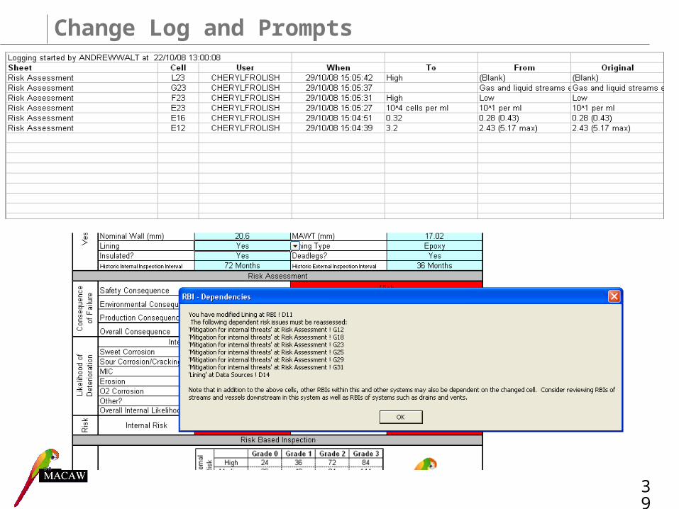
Change Log and Prompts
39
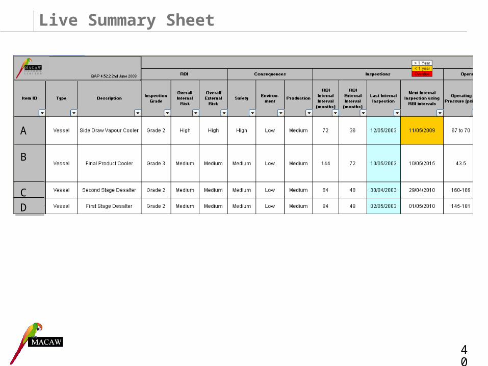
A
CD
B
Live Summary Sheet
40

Training and Technical Support
• Helpdesk set up for ongoing technical support
41
Date:Request
from:Contact details: Asset: RBI File name:
Q.A.P 4.26.108/10/2007
Request
MACAW RBI Help Request form
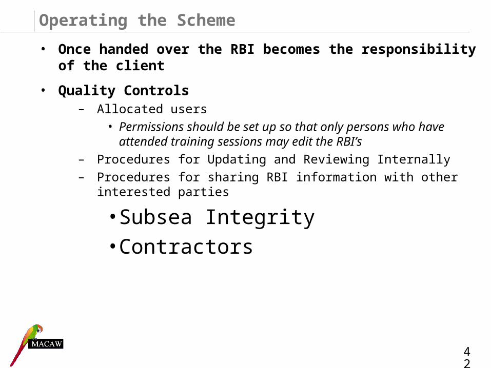
Operating the Scheme
• Once handed over the RBI becomes the responsibility of the client
• Quality Controls– Allocated users
• Permissions should be set up so that only persons who have attended training sessions may edit the RBI’s
– Procedures for Updating and Reviewing Internally
– Procedures for sharing RBI information with other interested parties
• Subsea Integrity
• Contractors
42
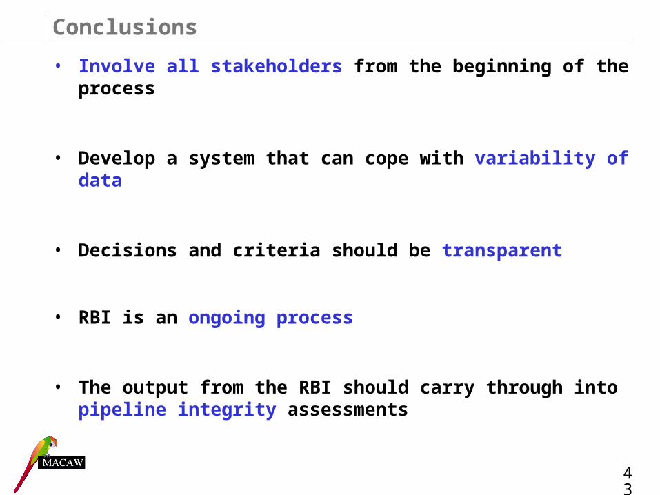
Conclusions
• Involve all stakeholders from the beginning of the process
• Develop a system that can cope with variability of data
• Decisions and criteria should be transparent
• RBI is an ongoing process
• The output from the RBI should carry through into pipeline integrity assessments
43

Thank you for your time,any questions?
44


