Proceedings in Manufacturing Systems, Volume 10, Issue 4, 2015, 183−188
ISSN 2067-9238
ROBOTIC DEBURRING CELL VIRTUAL PROTOTYPING
Andrei Mario IVAN 1, Adrian Florin NICOLESCU 2,*, Georgia Cezara AVRAM 3 and Liliana STAN4
1) Lect. PhD. eng., Machines and Manufacturing Systems Department, Politehnica University of Bucharest, Romania 2) Prof. PhD. eng., Machines and Manufacturing Systems Department, Politehnica University of Bucharest, Romania
3) Assistant PhD. eng., Machines and Manufacturing Systems Department, Politehnica University of Bucharest, Romania 4) Eng., MA Student, Machines and Manufacturing Systems Department, Politehnica University of Bucharest, Romania
Abstract: This paper presents the works performed by the authors in the field of robotic deburring applications. It describes the virtual prototyping and kinematic analysis of a robotic cell developed for plastic parts deburring. The cell layout includes a 6 degrees of freedom (DOF) articulated arm robot, a vacuum gripper for work piece manipulation and a deburring end-effector with radial compliance. The cell features one input and one output through two belt conveyors. After designing the layout of the cell and developing the 3D virtual prototype, the kinematic behavior of the robot, configurations and collision occurrence were evaluated using DMU Kinematics module inside CATIA V5 software. Key words: industrial robot, deburring, manufacturing cell, 3D virtual prototype, kinematics.-
1. INTRODUCTION 1
There is an established fact that, in today's industrial landscape, the robotic field has reached a certain level of maturity. Over the past 15−20 years the main producers have offered roughly the same industrial robot architectures and configurations − from this point of view, changes and innovations were deployed on the market, but at a much slower rate than the previous decades. Nevertheless, the robotics field remains a very dynamic one, with intensive research invested into it.
A first important research direction in the field of industrial robots is oriented towards optimization of robot internal structure, focused mainly on improvement of drives, motors and transmission. Producing a low-weight robot with a high payload and increased kinematic flexibility, while keeping the costs as low as possible, is the goal of any manufacturer. Also, as an integral part of the robotic deburring system, the structure of the end-effector is equally important for application performance [1].
Having reached a point where a well established range of architectures and configurations covered almost all compatible applications, the industrial robotics field shifted the main focus of its research towards the optimization of various robotic applications and integration of new technologies. Thus, the current state of the art in the field of industrial robotics puts more emphasis on improving overall robotized cell's functional parameters, integration of new features and technology into robotic cells and, most importantly, process simulation and optimization [2].
* Corresponding author: Politehnica University of Bucharest, Splaiul Independentei 313 Tel.: +40744923533; Fax: +40212691332 E-mail addresses: [email protected] (A. Nicolescu)
Taking into account the above considerations, the current paper presents the research performed by the authors regarding virtual prototyping, and analysis of a robotic deburring cell. Being one of the most well-suited tasks for industrial robots, deburring is currently the core of robotic machining applications due to its low power requirement and the increased flexibility needed to perform all the required operations. Deburring, being difficult to implement on machine tools, has been traditionally performed by hand, leading to bottlenecks in productivity and quality inconsistencies [3].
In order to perform a complete study of the proposed deburring cell, the article covers two main aspects [4]:
1. Robotic deburring cell 3D model developed using CATIA V5 software.
2. A kinematic study of the robotic deburring system using DMU Kinematics module of CATIA V5 and its importance regarding cell analysis and future steps in application development. 2. ROBOTIC DEBURRING CELL VIRTUAL
PROTOTYPE
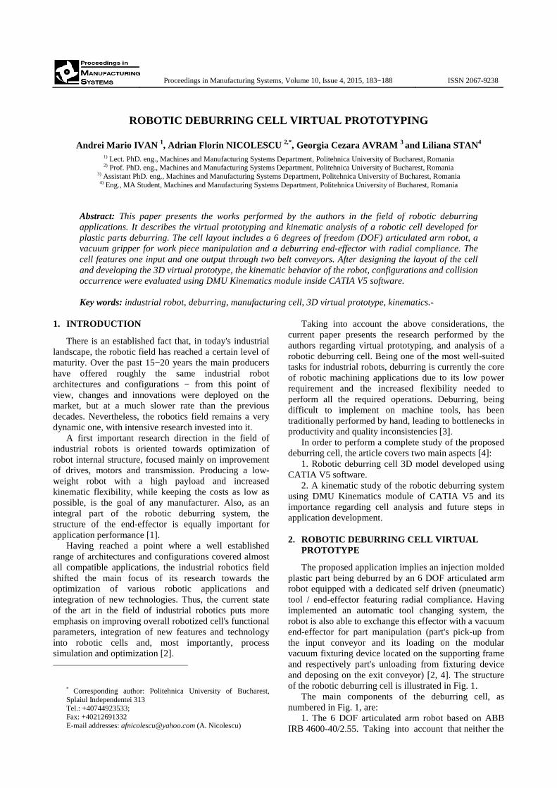
The proposed application implies an injection molded plastic part being deburred by an 6 DOF articulated arm robot equipped with a dedicated self driven (pneumatic) tool / end-effector featuring radial compliance. Having implemented an automatic tool changing system, the robot is also able to exchange this effector with a vacuum end-effector for part manipulation (part's pick-up from the input conveyor and its loading on the modular vacuum fixturing device located on the supporting frame and respectively part's unloading from fixturing device and deposing on the exit conveyor) [2, 4]. The structure of the robotic deburring cell is illustrated in Fig. 1.
The main components of the deburring cell, as numbered in Fig. 1, are:
1. The 6 DOF articulated arm robot based on ABB IRB 4600-40/2.55. Taking into account that neither the
184 A.M. Ivan et al. / Proceedings in Manufacturing Systems, Vol.
end-effectors, nor the part to be machined have significant weight, the most important criterion for choosing the robot to be integrated into the cell became the reach of the arm. Also, the 6 DOF articulated arm architecture was necessary in order to ensure the required kinematic flexibility [1, 4].
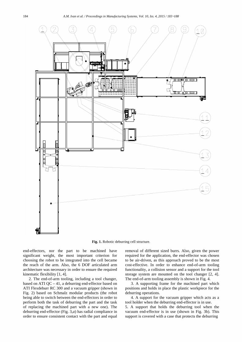
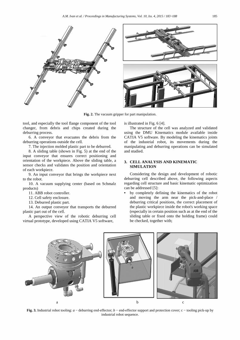
2. The end-of-arm tooling, including a tool changer, based on ATI QC – 41, a deburring endATI Flexdeburr RC 300 and a vacuum gripper (shown in Fig. 2) based on Schmalz modular products (the robot being able to switch between the end-effectors in order to perform both the task of deburring the part and the task of replacing the machined part with a new one). The deburring end-effector (Fig. 3,a) has radial compliance in order to ensure consistent contact with the part and equal
/ Proceedings in Manufacturing Systems, Vol. 10, Iss. 4, 2015 / 183−1
Fig. 1. Robotic deburring cell structure.
effectors, nor the part to be machined have
significant weight, the most important criterion for rated into the cell became
the reach of the arm. Also, the 6 DOF articulated arm architecture was necessary in order to ensure the required
arm tooling, including a tool changer, end-effector based on
ATI Flexdeburr RC 300 and a vacuum gripper (shown in Fig. 2) based on Schmalz modular products (the robot
effectors in order to perform both the task of deburring the part and the task
g the machined part with a new one). The ) has radial compliance in
order to ensure consistent contact with the part and equal
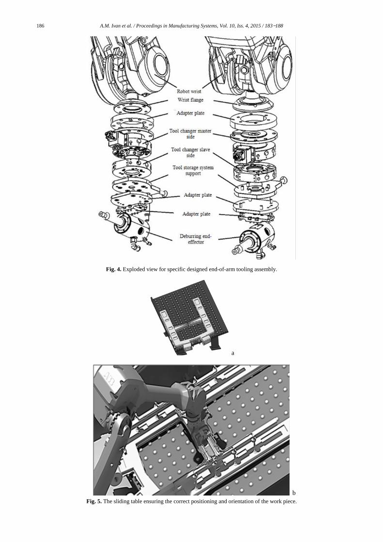
removal of different sized burrs. Also, given the power required for the application, the to be air-driven, as this approach proved to be the most cost-effective. In order to enhance endfunctionality, a collision sensor and a support for the tool storage system are mounted on the tool changer [2, 4].The end-of-arm tooling assembly is shown in Fig. 4
3. A supporting frame for the machined part which positions and holds in place the plastic workpiece for the deburring operations.
4. A support for the vacuum gripper which acts as a tool holder when the deburring end5. A support that holds the deburring tool when the vacuum end-effector is in use (shown in Fig. 3b). This support is covered with a case that protects the deburring
188
removal of different sized burrs. Also, given the power required for the application, the end-effector was chosen
driven, as this approach proved to be the most effective. In order to enhance end-of-arm tooling
functionality, a collision sensor and a support for the tool storage system are mounted on the tool changer [2, 4].
arm tooling assembly is shown in Fig. 4. 3. A supporting frame for the machined part which
positions and holds in place the plastic workpiece for the
4. A support for the vacuum gripper which acts as a rring end-effector is in use.
5. A support that holds the deburring tool when the effector is in use (shown in Fig. 3b). This
support is covered with a case that protects the deburring
A.M. Ivan et al. / Proceedings in Manufacturing Systems, Vol. 10, Iss. 4, 2015 / 183−188 185
Fig. 2. The vacuum gripper for part manipulation.
tool, and especially the tool flange component of the tool changer, from debris and chips created during the deburring process.
6. A conveyor that evacuates the debris from the deburring operations outside the cell.
7. The injection molded plastic part to be deburred. 8. A sliding table (shown in Fig. 5) at the end of the
input conveyor that ensures correct positioning and orientation of the workpiece. Above the sliding table, a sensor checks and validates the position and orientation of each workpiece.
9. An input conveyor that brings the workpiece next to the robot.
10. A vacuum supplying center (based on Schmalz products)
11. ABB robot controller. 12. Cell safety enclosure. 13. Deburred plastic part. 14. An output conveyor that transports the deburred
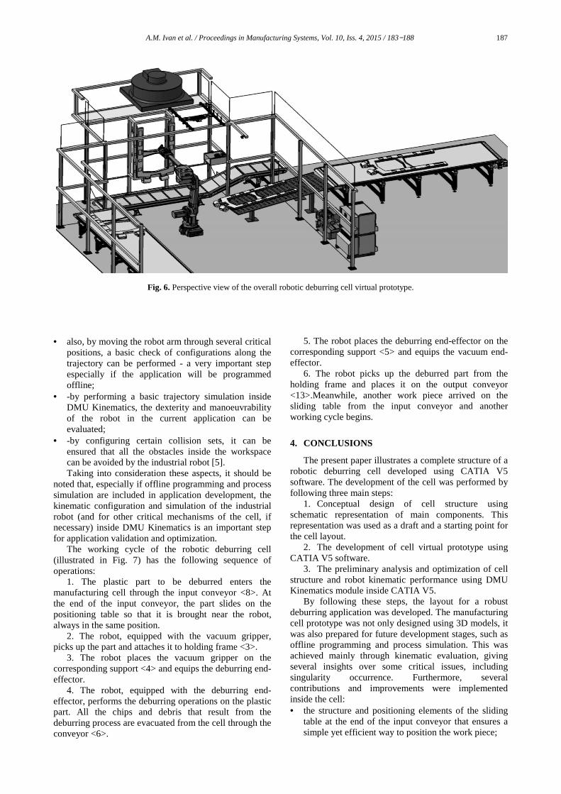
plastic part out of the cell. A perspective view of the robotic deburring cell
virtual prototype, developed using CATIA V5 software,
is illustrated in Fig. 6 [4]. The structure of the cell was analyzed and validated
using the DMU Kinematics module available inside CATIA V5 software. By modeling the kinematics joints of the industrial robot, its movements during the manipulating and deburring operations can be simulated and studied.
3. CELL ANALYSIS AND KINEMATIC
SIMULATION
Considering the design and development of robotic deburring cell described above, the following aspects regarding cell structure and basic kinematic optimization can be addressed [5]: • by completely defining the kinematics of the robot
and moving the arm near the pick-and-place / deburring critical positions, the correct placement of the plastic workpiece inside the robot's working space (especially in certain position such as at the end of the sliding table or fixed onto the holding frame) could be checked, together with;
a b c
Fig. 3. Industrial robot tooling: a − deburring end-effector; b − end-effector support and protection cover; c − tooling pick-up by
industrial robot sequence.
186 A.M. Ivan et al. / Proceedings in Manufacturing Systems, Vol. 10, Iss. 4, 2015 / 183−188
Fig. 4. Exploded view for specific designed end-of-arm tooling assembly.
a
b
Fig. 5. The sliding table ensuring the correct positioning and orientation of the work piece.
A.M. Ivan et al. / Proceedings in Manufacturing Systems, Vol. 10, Iss. 4, 2015 / 183−188 187
Fig. 6. Perspective view of the overall robotic deburring cell virtual prototype.
• also, by moving the robot arm through several critical
positions, a basic check of configurations along the trajectory can be performed - a very important step especially if the application will be programmed offline;
• -by performing a basic trajectory simulation inside DMU Kinematics, the dexterity and manoeuvrability of the robot in the current application can be evaluated;
• -by configuring certain collision sets, it can be ensured that all the obstacles inside the workspace can be avoided by the industrial robot [5]. Taking into consideration these aspects, it should be
noted that, especially if offline programming and process simulation are included in application development, the kinematic configuration and simulation of the industrial robot (and for other critical mechanisms of the cell, if necessary) inside DMU Kinematics is an important step for application validation and optimization.
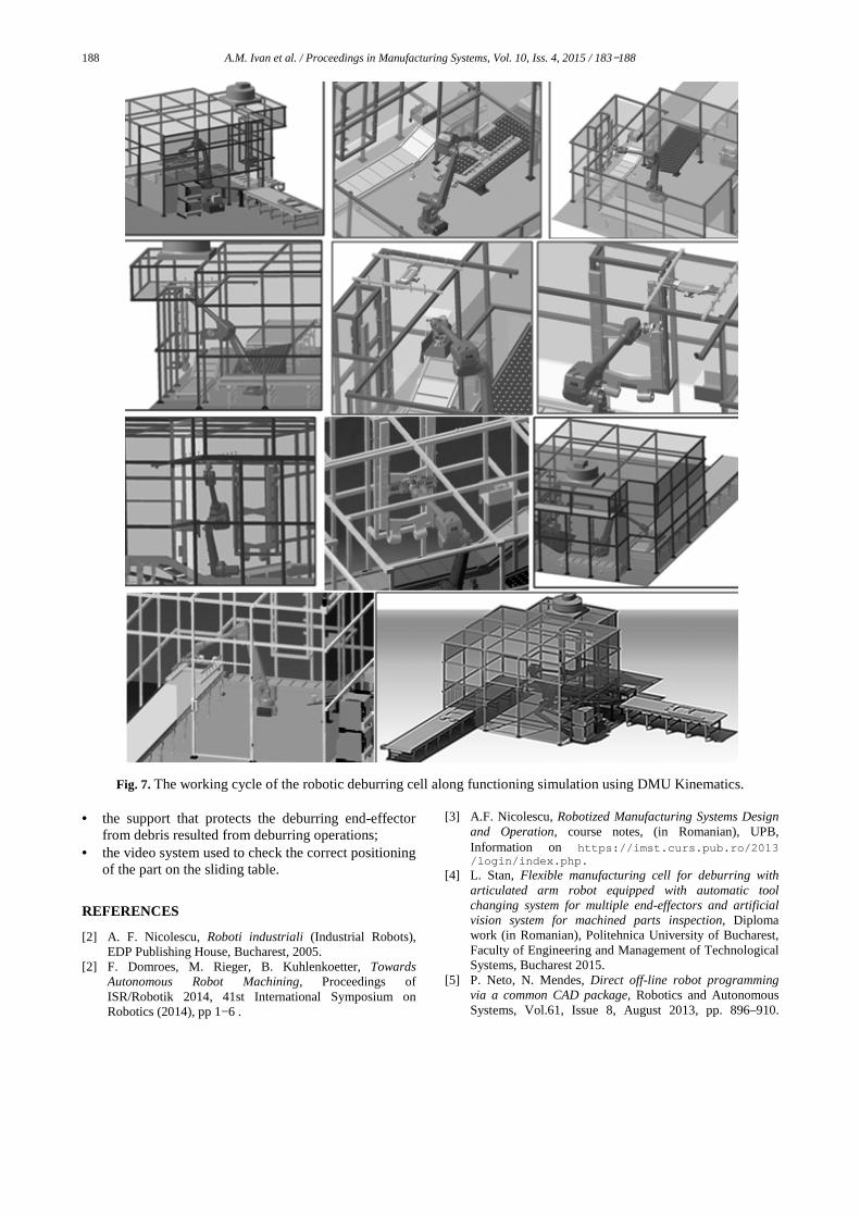
The working cycle of the robotic deburring cell (illustrated in Fig. 7) has the following sequence of operations:
1. The plastic part to be deburred enters the manufacturing cell through the input conveyor <8>. At the end of the input conveyor, the part slides on the positioning table so that it is brought near the robot, always in the same position.
2. The robot, equipped with the vacuum gripper, picks up the part and attaches it to holding frame <3>.
3. The robot places the vacuum gripper on the corresponding support <4> and equips the deburring end-effector.
4. The robot, equipped with the deburring end-effector, performs the deburring operations on the plastic part. All the chips and debris that result from the deburring process are evacuated from the cell through the conveyor <6>.
5. The robot places the deburring end-effector on the corresponding support <5> and equips the vacuum end-effector.
6. The robot picks up the deburred part from the holding frame and places it on the output conveyor <13>.Meanwhile, another work piece arrived on the sliding table from the input conveyor and another working cycle begins.
4. CONCLUSIONS
The present paper illustrates a complete structure of a robotic deburring cell developed using CATIA V5 software. The development of the cell was performed by following three main steps:
1. Conceptual design of cell structure using schematic representation of main components. This representation was used as a draft and a starting point for the cell layout.
2. The development of cell virtual prototype using CATIA V5 software.
3. The preliminary analysis and optimization of cell structure and robot kinematic performance using DMU Kinematics module inside CATIA V5.
By following these steps, the layout for a robust deburring application was developed. The manufacturing cell prototype was not only designed using 3D models, it was also prepared for future development stages, such as offline programming and process simulation. This was achieved mainly through kinematic evaluation, giving several insights over some critical issues, including singularity occurrence. Furthermore, several contributions and improvements were implemented inside the cell: • the structure and positioning elements of the sliding
table at the end of the input conveyor that ensures a simple yet efficient way to position the work piece;
188 A.M. Ivan et al. / Proceedings in Manufacturing Systems, Vol. 10, Iss. 4, 2015 / 183−188
Fig. 7. The working cycle of the robotic deburring cell along functioning simulation using DMU Kinematics.
• the support that protects the deburring end-effector from debris resulted from deburring operations;
• the video system used to check the correct positioning of the part on the sliding table.
REFERENCES
[2] A. F. Nicolescu, Roboti industriali (Industrial Robots), EDP Publishing House, Bucharest, 2005.
[2] F. Domroes, M. Rieger, B. Kuhlenkoetter, Towards Autonomous Robot Machining, Proceedings of ISR/Robotik 2014, 41st International Symposium on Robotics (2014), pp 1−6 .
[3] A.F. Nicolescu, Robotized Manufacturing Systems Design and Operation, course notes, (in Romanian), UPB, Information on https://imst.curs.pub.ro/2013 /login/index.php.
[4] L. Stan, Flexible manufacturing cell for deburring with articulated arm robot equipped with automatic tool changing system for multiple end-effectors and artificial vision system for machined parts inspection, Diploma work (in Romanian), Politehnica University of Bucharest, Faculty of Engineering and Management of Technological Systems, Bucharest 2015.
[5] P. Neto, N. Mendes, Direct off-line robot programming via a common CAD package, Robotics and Autonomous Systems, Vol.61, Issue 8, August 2013, pp. 896–910.


