RPP-RPT-48549 Rev. 1
ES-1
EXECUTIVE SUMMARY
This report analyzes the availability and suitability of specific sites within the Hanford Site
boundary for locating the Supplemental Treatment System and Immobilization System. This is a
macro-level qualitative analysis that considers the Treatment System and the Immobilization
System as two separate entities that must work jointly with one another and with the Waste
Treatment and Immobilization Plant (WTP) to accomplish the tank waste treatment mission.
This macro-level qualitative analysis is necessitated by the fact that the site evaluation has been
performed prior to the selection of the preferred alternative for the Immobilization System.
Nevertheless, a preliminary site selection is made independent of a preferred Immobilization
System alternative selection via a screening process that rules out site locations requiring major
upgrades to the Tank Farm System while supporting additional Supplemental Treatment
Program mission objectives (e.g., 2020 Vision for WTP Project Transition to Operations).
The non-quantitative evaluation showed a slight bias to locating both the Treatment and
Immobilization Systems in the 200 East Area. This was due to the fact the 200 East Area
locations exhibited the following advantages:
1. Proximity to feed sources – from both Double-shell Tanks (DSTs) and WTP
Pretreatment (PT)
2. Supportive of other initiatives – e.g., 2020 Vision and backup feed to the WTP LAW
Facility;
3. Previous Interim Pretreatment System (IPS) project work eliminates uncertainties
regarding site-specific requirements such as seismic response design criteria;
4. In-tank treatment option implementation is not restricted to one DST; and
5. If the Immobilization System technology is 2nd
LAW, the WTP site will host the 2nd
LAW facility and a 200 East Area Treatment System will be “co-located”.
Design for the Treatment System is therefore performed assuming that both the Treatment
System and the Immobilization System would be located in the 200 East Area.
It is recognized that this site evaluation will require periodic updates and a formal, quantitative
site evaluation will be performed subsequent to the selection of the preferred Immobilization
System alternative.
RPP-RPT-48549 Rev. 1
i
TABLE OF CONTENTS
1.0 SCOPE ............................................................................................................................. 1-1
1.1 SUPPLEMENTAL TREATMENT PROGRAM OVERVIEW .......................... 1-1
1.2 SUMMARY ......................................................................................................... 1-2
2.0 METHODOLOGY FOR EVALUATING SITES ........................................................... 2-1
2.1 BACKGROUND ................................................................................................. 2-2
2.1.1 Treatment System .................................................................................... 2-2
2.1.2 Immobilization System ............................................................................ 2-2
3.0 REQUIREMENTS AND SYSTEM CHARACTERISICS ............................................. 3-1
3.1 FACILITY SIZE AND CAPACITY ................................................................... 3-2
3.2 WTP PRETREATMENT FACILITY ................................................................. 3-4
3.3 SITE INFRASTRUCTURE NEEDS ................................................................... 3-4
3.3.1 Electrical Power Distribution ................................................................... 3-4
3.3.2 Site Water Distribution ............................................................................ 3-5
3.3.3 Telecommunication (Phone, HLAN) ....................................................... 3-5
3.3.4 Roadways ................................................................................................. 3-5
3.3.5 Other Site Services ................................................................................... 3-5
3.4 NUCLEAR SAFETY CONSIDERATIONS ....................................................... 3-6
3.5 INDUSTRIAL AND RADIOLOGICAL SAFETY CONSIDERATIONS ......... 3-6
3.6 SIESMIC CRITERIA .......................................................................................... 3-7
3.6.1 Treatment System .................................................................................... 3-8
3.6.2 Immobilization System ............................................................................ 3-8
3.7 ENVIRONMENTAL AND PERMITS ............................................................... 3-9
4.0 PRELIMINARY SCREENING ....................................................................................... 4-1
4.1 SPLIT CAPACITY IMMOBILIZATION SYSTEM IN WEST AND
EAST AREAS ................................................................................................... 4-10
4.2 TREATMENT SYSTEM AND IMMOBILIZATION SYSTEM
LOCATED IN EAST AREA ............................................................................. 4-11
5.0 AVAILIBILITY OF SITES ............................................................................................. 5-1
5.1 CANDIDATE SITES IN 200 EAST AREA ....................................................... 5-1
5.1.1 East Area In-tank Treatment System Location ........................................ 5-3
5.2 CANDIDATE SITES IN 200 WEST AREA....................................................... 5-4
5.2.1 West Area In-tank Treatment System Location....................................... 5-7
6.0 FORMAL EVALUATION OF SITES ............................................................................ 6-1
6.1 EVALUATION CRITERIA AND WEIGHTING............................................... 6-1
6.1.1 Description of Criteria Considered .......................................................... 6-1
6.1.2 Criteria Weighting ................................................................................... 6-4
6.2 EVALUATION RESULTS ................................................................................. 6-4
RPP-RPT-48549 Rev. 1
ii
7.0 CONCLUSIONS.............................................................................................................. 7-1
8.0 REFERENCES ................................................................................................................ 8-1
APPENDIX A –IMMOBILIZATION FACILITY LAYOUT AND ELEVATION
VIEWS ................................................................................................................................. I
APPENDIX B – PHOTO LOG OF 200 EAST AREA CANDIDATE SITES
WALKDOWN ..................................................................................................................... I
APPENDIX C – PHOTO LOG OF 200 WEST AREA CANDIDATE SITES
WALKDOWN ..................................................................................................................... I
LIST OF FIGURES
Figure 3-1. Treatment and Immobilization System Input – Output Diagram ........................... 3-1
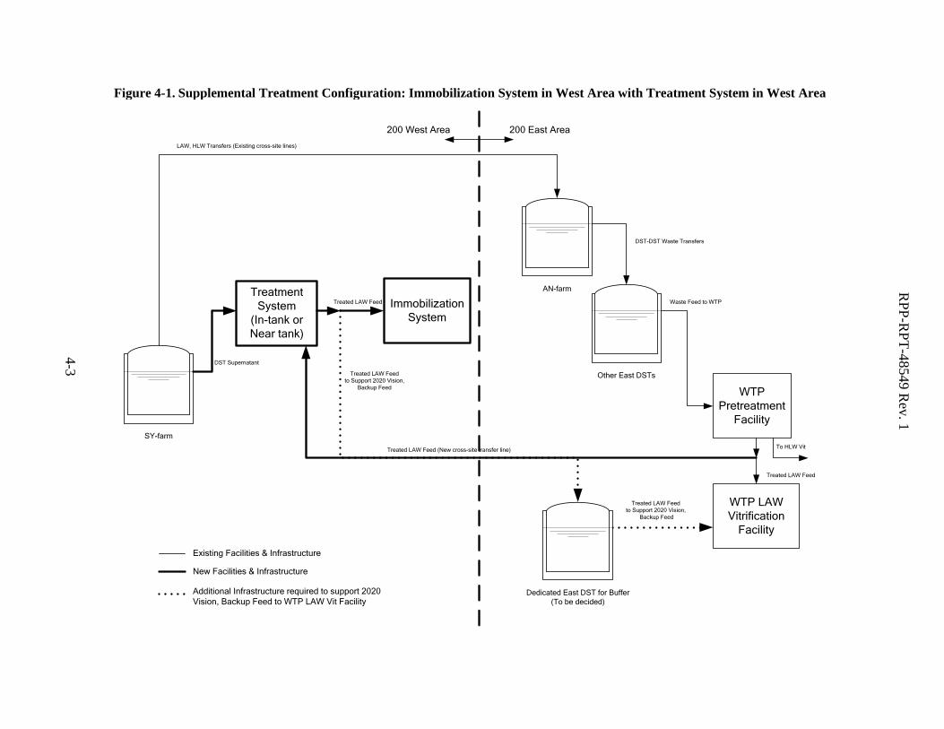
Figure 4-1. Supplemental Treatment Configuration: Immobilization System in West
Area with Treatment System in West Area ............................................................ 4-3
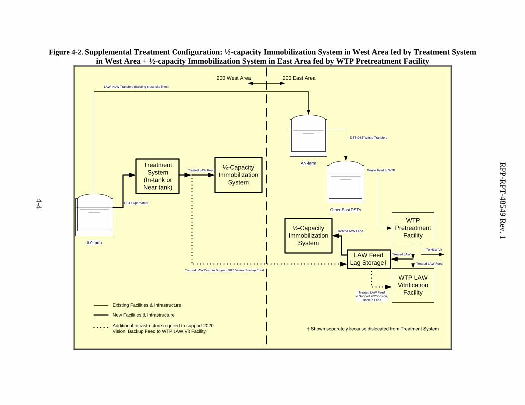
Figure 4-2. Supplemental Treatment Configuration: ½-capacity Immobilization System
in West Area fed by Treatment System in West Area + ½-capacity
Immobilization System in East Area fed by WTP Pretreatment Facility ............... 4-4
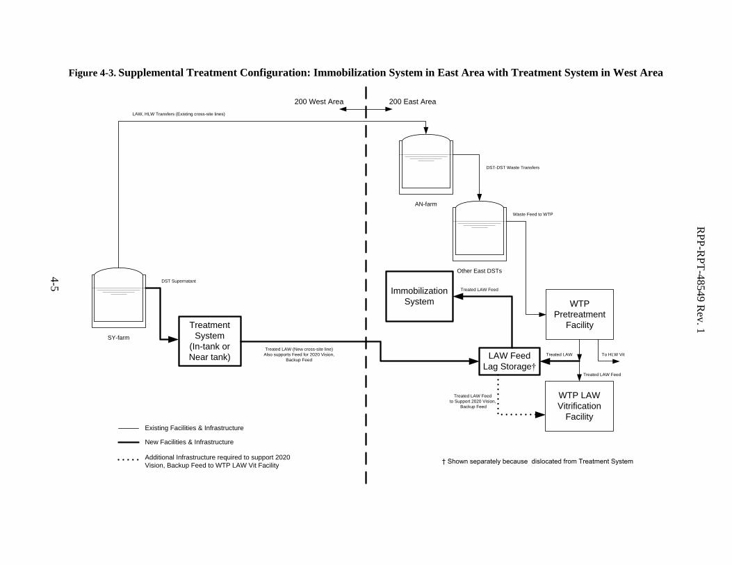
Figure 4-3. Supplemental Treatment Configuration: Immobilization System in East
Area with Treatment System in West Area ............................................................ 4-5
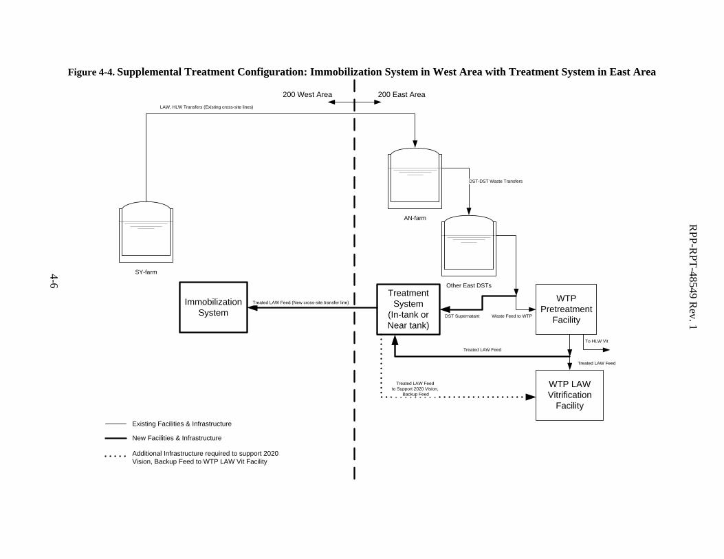
Figure 4-4. Supplemental Treatment Configuration: Immobilization System in West
Area with Treatment System in East Area .............................................................. 4-6
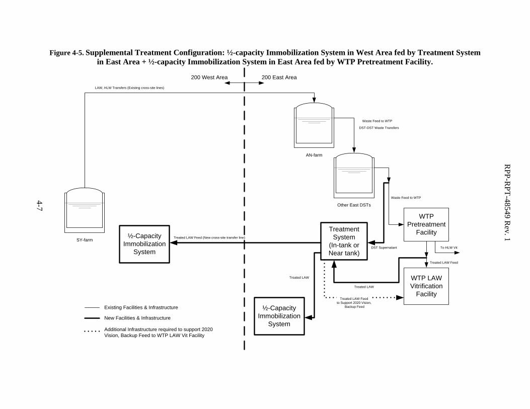
Figure 4-5. Supplemental Treatment Configuration: ½-capacity Immobilization System
in West Area fed by Treatment System in East Area + ½-capacity
Immobilization System in East Area fed by WTP Pretreatment Facility. .............. 4-7
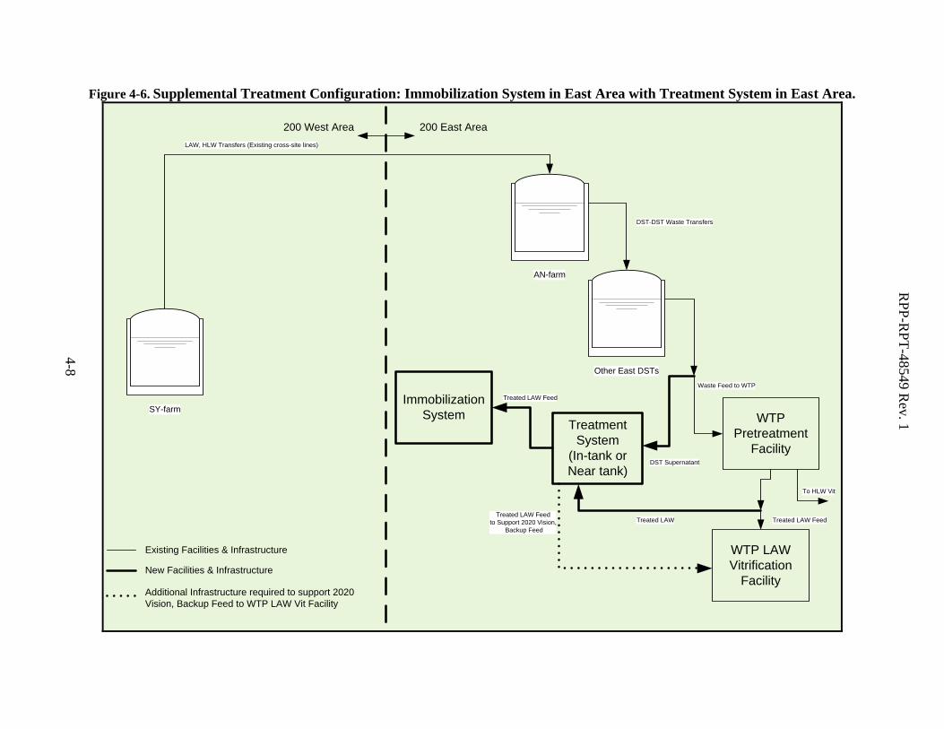
Figure 4-6. Supplemental Treatment Configuration: Immobilization System in East
Area with Treatment System in East Area. ............................................................. 4-8
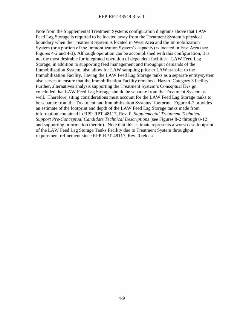
Figure 4-7. LAW Feed Lag Storage Tanks Facility Footprint. ............................................... 4-10
Figure 5-1. Treatment and Immobilization System Candidate Sites in East Area.* ................. 5-2
Figure 5-2. Aerial Photograph of AP Tank Farm. ..................................................................... 5-4
Figure 5-3. Treatment and Immobilization System Candidate Sites in 200 West Area* .......... 5-5
Figure 5-4. Aerial Photograph of SY Tank Farm. ..................................................................... 5-7
RPP-RPT-48549 Rev. 1
iii
LIST OF TABLES
Table 3-1. Treatment and Immobilization System Characteristics. ............................................ 3-3
Table 3-2. Guidance for SDC Based on Unmitigated Consequences of SSC Failures in a
Seismic Event.......................................................................................................... 3-3
Table 4-1. Treatment and Immobilization System Locations Considered. ................................ 4-2
Table 5-1. 200 West Area Candidate Site Features. ................................................................... 5-6
Table 6-1. Example Criteria for Treatment and Immobilization System Site Evaluation. ......... 6-2
RPP-RPT-48549 Rev. 1
iv
LIST OF TERMS
ANSI American National Standards Institute
BPA Bonneville Power Administration
CFF cross-flow filtration
CST Crystalline Silicotitanate
DOE US Department of Energy
DOE-ORP US Department of Energy, Office of River Protection
DOH/WSDOH Washington State Department of Health
DST double-shell tank
ERDF Environmental Restoration Disposal Facility
ERP External Review Panel
ETF Effluent Treatment Facility
FBSR fluidized bed steam reformer
FRP fiberglass reinforced plastic
HFFACO Hanford Federal Facility Agreement and Consent Order
HLAN Hanford Local Area Network
HLW High-level waste
HTWOS Hanford Tank Waste Operations Simulator
IBC International Building Code
IDF Integrated Disposal Facility
IPS Interim Pretreatment System
IX ion exchange
LAW low-activity waste
MSA Mission Support Alliance
MT metric tons
NFPA National Fire Protection Association
PC Performance Category
PT pretreatment
PVC polyvinyl chloride
PNNL Pacific Northwest National Laboratory
RMF rotary micro filtration
RPP River Protection Project
SCIX Small Column Ion Exchange
SMP submersible mixer pumps
sRF spherical resorcinol-formaldehyde
SSC Structure, System and Component
SVF spreadsheet verification form
TPA Tri-Party Agreement
TSB Technology Selection Board
TSR Technical Safety Requirement
URMA underground radioactive material area
WFD waste feed delivery
WIDS Waste Information Database System
WRPS Washington River Protection Solutions, LLC
WSDOT Washington State Department of Transportation
WTP Waste Treatment and Immobilization Plant
RPP-RPT-48549 Rev. 1
1-1
1.0 SCOPE
This site evaluation report analyzes the availability and suitability of different sites within the
Hanford Site boundary for locating the Supplemental Treatment Program systems. This
evaluation is based on criteria for safe, reliable, and cost-effective accomplishment of the tank
waste treatment mission.
Supplemental Treatment Program systems are:
1. The Treatment System – Receives Double-shell Tank (DST) supernatant and removes
solids and 137
Cs to produce a liquid waste feed stream suitable for treatment in the
Immobilization System1; and
2. The Immobilization System – Receives treated LAW feed from the Treatment System
and the WTP Pretreatment (PT) facility, and produces a stable, immobilized waste form
suitable for on-site disposal.
Note that this site evaluation report is being produced prior to completion of the Immobilization
System conceptual design; and, as such, this site evaluation does not have the benefit of
technology selection for the Immobilization System. Four unique Immobilization technologies
are viable candidates for implementation as the Immobilization System2. Although the
recommended Treatment System conceptual design alternative is an in-tank deployment of
Treatment System equipment (see RPP-RPT-50024, Rev. 0, Treatment Project T4S01
Conceptual Design Report), this site evaluation will continue to carry the near-tank Treatment
System deployment option, consistent with Revision 0 of this document. Formal DOE ORP
acceptance of the In-tank Treatment System configuration recommendation will allow removal
of the near-tank configuration in a future revision of this site evaluation.
1.1 SUPPLEMENTAL TREATMENT PROGRAM OVERVIEW
The U.S. Department of Energy (DOE), Office of River Protection’s (ORP) primary mission is
to retrieve and treat Hanford’s tank waste and close the tank farms to protect the Columbia
River. Mixed radioactive waste is stored in 177 underground tanks at the Hanford Site as
reported in DOE/ORP-2003-02, Environmental Impact Statement for Retrieval, Treatment, and
Disposal of Tank Waste and Closure of the Single-Shell Tanks at the Hanford Site, Richland WA,
Inventory and Source Term Data Package. As of July 2010, those 177 underground tanks were
estimated to contain about 56 million gallons of waste. The volume varies depending on how
much water is added during waste retrieval and how much of that water has been removed by the
242-A evaporator facility. Retrieval and treatment of Hanford’s tank wastes create secondary
1 The Treatment System also has the potential to provide feed for the WTP LAW Vitrification facility in support of
the 2020 Vision of WTP Project Transition to Operations and to support WTP LAW Vitrification in case of WTP
Pretreatment facility delays or outages. 2 In addition, an option for removal of the pertechnetate form of Technetium-99 (
99Tc) from the feed to the
Immobilization Facility is also being considered. This option would be beneficial to all four of the immobilization
technologies being considered.
RPP-RPT-48549 Rev. 1
1-2
liquid waste streams that also require treatment and disposal as documented in ORP-11242,
River Protection Project System Plan.
The DOE ORP is responsible for management and completion of the River Protection Project
(RPP) mission, which comprises both the Hanford Site tank farms and the WTP. Hanford
Federal Facility Agreement and Consent Order (HFFACO or Tri-Party Agreement [TPA])
requires DOE to complete the RPP tank waste treatment mission by September 30, 2047. A key
aspect of implementing that mission is to construct and operate the WTP (see ORP-11242). The
WTP is a multi-facility plant that will separate and immobilize the tank high-level waste (HLW)
and low-activity waste (LAW) fractions for final disposition. The WTP LAW Vitrification
Facility is sized to treat less than 50% of the approximately 51,000 metric tons (MT) of sodium
present in the tank waste requiring treatment by 2047.
The current RPP baseline plan assumes deployment of a supplemental treatment capability, with
net capacity calculated so that LAW treatment does not drive the mission duration. Without
additional LAW treatment capacity, the mission would extend an additional 40 years beyond the
September 30, 2047 deadline. The lifecycle cost of tank waste cleanup is strongly influenced by
the WTP operating duration. Each year the WTP operates beyond the 2047 deadline, taxpayer
cost is approximately $1 billion, in today’s dollars. Therefore, a significant life-cycle cost
incentive exists to complete tank waste processing at the earliest practical date.
The Supplemental Treatment Program is required to support completion of the TPA milestone
M-062-00, completion of LAW processing by FY 2047.
1.2 SUMMARY
This site evaluation concludes with a preliminary site selection to enable design of the Treatment
System, based on criteria that are independent of technology selection. It is understood that
Immobilization System technology selection could significantly alter this selection. It is
therefore imperative that Treatment System design solutions do not preclude deployment on
other candidate sites. Further, it is understood that this report will be updated, at a minimum,
subsequent to the Immobilization System technology selection.
The report is organized as follows:
Section 2.0 describes the two-step methodology used to enable evaluation of the sites
prior to Immobilization technology selection.
Section 3.0 describes the requirements and system characteristics important to the site
evaluation.
Section 4.0 describes the preliminary screening of sites that narrow the possible options
for locating Treatment and Immobilization Systems in the 200 East and/or 200 West
Areas.
Section 5.0 describes candidate sites that satisfy space and proximity criteria for siting the
facilities.
Section 6.0 describes the formal evaluation of the candidate sites. Note that the contents
of this section serve as a placeholder and provide examples for information to be placed
in this section subsequent to Immobilization System technology down select.
Section 7.0 concludes the report with a preliminary site selection for the Treatment
System design basis, based on information gathered herein.
RPP-RPT-48549 Rev. 1
2-1
2.0 METHODOLOGY FOR EVALUATING SITES
Consideration is given to both the Treatment System and Immobilization System in this site
evaluation so that a practical, cost effective solution for locating these systems is achieved for the
Supplemental Treatment Program.
A two-step process that narrows possible combinations of Supplemental Treatment Program
system locations was followed:
Step 1. Preliminary Screening – Narrow the selection of possible locations of the systems
in various combinations of 200 East and 200 West Area locations independent of
Treatment and Immobilization System technology selections. Screening criteria for
determining whether a site will be carried forward for consideration in Step 2
include whether candidate locations require major tank farm upgrades to support the
location. Major upgrades include new DSTs and/or a new cross-site transfer
system. Hanford Tank Waste Operations Simulator (HTWOS) model runs were
used to validate system configurations that pass the preliminary screening.
Step 2. Formal Evaluation – Take forward viable system location configurations for further
evaluation, considering Treatment and Immobilization Systems design basis
information and candidate site characteristics. A major task in this step is to
establish suitable candidate sites and characterize them in terms of land availability,
accessibility of anticipated infrastructure needs, and environmental impact.
Candidate sites’ characteristics important to this site evaluation include:
Candidate site size and geometry;
General site condition. For example,
Site topography;
Disturbed vs. undisturbed land; and
Site proximity to waste sites such as underground radioactive materials areas
(URMAs) and active/inactive underground waste transfer lines or chemical sewer
lines.
Candidate site relationship to existing infrastructure, including:
Proximity to waste feed source – DST farm and waste transfer system tie-in locations;
Major utility locations and available capacity (e.g., 13.8 kV electrical power, raw and
potable water, sanitary sewer).
Candidate site characteristics’ are gathered via interactions with the Mission Support Alliance
(MSA) Land and Facilities Management organization; Query Map (QMap) web-based Hanford
site map application, including its link to the Waste Information Database System (WIDS); and
site walk downs.
RPP-RPT-48549 Rev. 1
2-2
2.1 BACKGROUND
The following sections discuss background information relevant to evaluating suitable sites for
the Treatment and Immobilization Systems.
2.1.1 Treatment System
A six-member Technology Selection Board (TSB) comprised of Washington River Protection
Solutions, LLC (WRPS) staff was convened to review, evaluate, and select the preferred set of
treatment technologies that will be formally recommended to the U.S. Department of Energy,
Office of River Protection, in support of the Supplemental Treatment Project Critical Decision-1
(CD-1) submittal. This review and evaluation was performed in accordance with a multi-
attribute decision-making process, as documented in RPP-PLAN-47748, Treatment Technology
Selection Plan in Support of the Supplemental Treatment Program.
Based on the TSBs evaluation, the following Treatment System technologies will be used:
Filtration as the method to remove solids from the tank waste stream, and
Ion Exchange (IX) as the method to remove 137
Cs from the filtrate.
Similarly, a separate alternatives analyses followed and was performed during Treatment System
conceptual design to determine:
1. Waste stream filtration technology – Cross-flow Filtration (CFF) or Rotary Micro
Filtration (RMF);
2. Treatment System location – In-tank or near-tank (e.g., underground, vault based); and
3. Ion exchange media – Elutable (e.g., Spherical Resorcinol-formaldehyde [sRF]) vs. non-
elutable media (e.g., Crystalline Silicotitanate [CST])
The alternatives analysis was based on engineering data compiled by the Treatment System
conceptual design A/E (EnergySolutions). An independent alternative selection team (AST)
comprised of WRPS representatives from tank farm facility management (operations), system
engineering, environmental compliance, nuclear safety and licensing, base operations process
engineering, project engineering, project management as well as Savannah River Site (SRS)
Small Column Ion Exchange (SCIX) program engineering was convened to develop selection
criteria and to evaluate the engineering data developed for Treatment System alternatives. RPP-
RPT-49721, Rev. 0, Treatment Project (T4S01): Alternative Analysis Evaluation and Selection
Report documents the decision and rationale for developing two basic Treatment System
configurations for conceptual design:
1. A near-tank deployment of CFF and IX with elutable sRF resin; and
2. An in-tank deployment of RMF and IX with non-elutable CST IX media
Although RPP-RPT-50024, Rev. 0, recommends the in-tank configuration using RMF and IX
with sRF resin for preliminary design development, this report will continue to refer to the
potential sites for near-tank Treatment System deployment developed for Revision 0 of this
document until formal DOE ORP acceptance of this recommendation.
2.1.2 Immobilization System
The DOE-ORP appointed External Review Panel (ERP) has the responsibility to select a
preferred Immobilization System option from the following four candidate technologies:
RPP-RPT-48549 Rev. 1
2-3
2nd
LAW Vitrification, based on the WTP LAW Vitrification Facility;
Fluidized Bed Steam Reforming (FBSR);
Bulk Vitrification; and
Cast Stone
This site evaluation assumes that one of these four technologies will be selected and also gathers
facility footprint and infrastructure needs for each.
RPP-RPT-48549 Rev. 1
3-1
3.0 REQUIREMENTS AND SYSTEM CHARACTERISICS
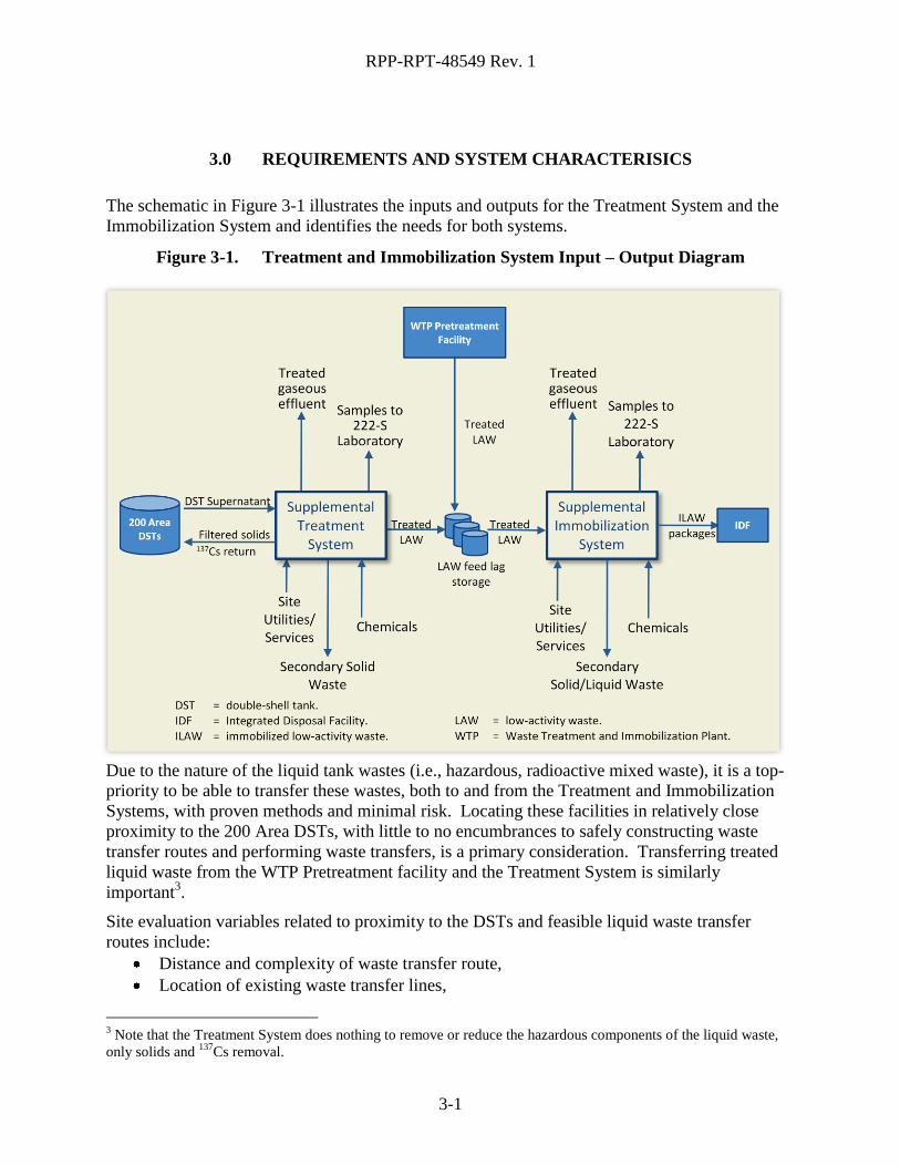
The schematic in Figure 3-1 illustrates the inputs and outputs for the Treatment System and the
Immobilization System and identifies the needs for both systems.
Figure 3-1. Treatment and Immobilization System Input – Output Diagram
Due to the nature of the liquid tank wastes (i.e., hazardous, radioactive mixed waste), it is a top-
priority to be able to transfer these wastes, both to and from the Treatment and Immobilization
Systems, with proven methods and minimal risk. Locating these facilities in relatively close
proximity to the 200 Area DSTs, with little to no encumbrances to safely constructing waste
transfer routes and performing waste transfers, is a primary consideration. Transferring treated
liquid waste from the WTP Pretreatment facility and the Treatment System is similarly
important3.
Site evaluation variables related to proximity to the DSTs and feasible liquid waste transfer
routes include:
Distance and complexity of waste transfer route,
Location of existing waste transfer lines,
3 Note that the Treatment System does nothing to remove or reduce the hazardous components of the liquid waste,
only solids and 137
Cs removal.
RPP-RPT-48549 Rev. 1
3-2
Characteristics of new waste transfer lines (additional lines or taps into existing lines),
Disturbance of significant structures or site features (e.g., existing waste sites, site
topography, roads, power lines, water lines, sewer lines, active or inactive structures), and
Disturbance of environmentally-sensitive areas.
Secondary liquid waste streams to the Effluent Treatment Facility (ETF), secondary solid waste
streams to a permitted disposal facility, and samples to the 222-S Lab are next in importance; but
because these wastes can be transported over road, if necessary, the treatment and
immobilization systems’ location relative to the ETF and a disposal facility are of secondary
importance to the site selection.
Site services, such as electrical power; water; telecommunications (e.g., telephone, HLAN); road
access for chemical deliveries and immobilized waste transport; and emergency services (e.g.,
fire, ambulance) are of lesser concern in that these services can be made available site-wide.
However, these services must not be removed from consideration when performing the site
evaluation. All other considerations being equal, site services can provide discriminating factors
that may lead to favoring one location over another. Site services are addressed in more detail
later in this section.
Other major considerations related to the requirements and system characteristics for the site
evaluation include facility size and capacity; constraints related to the WTP Pretreatment facility;
nuclear and industrial safety considerations; seismic criteria, environmental considerations and
permits; and unique site related requirements. These considerations are addressed in more detail
in the following sections.
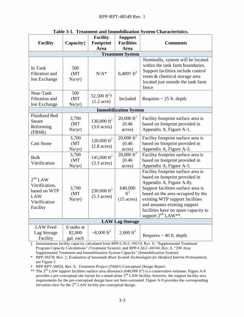
3.1 FACILITY SIZE AND CAPACITY
The facility sizes and estimated treatment capacities for the Treatment System and
Immobilization System are listed in Table 3-1. The facility footprint estimates for the Treatment
System are based on conceptual layouts given in released reports, as noted in Table 3-1; footprint
estimates for the Immobilization System alternatives are a result of the preliminary facility
layouts included in Appendix A.
The surface area requirements for the Treatment System options are substantially less than those
required for the Immobilization System options. Treatment System footprint estimates are also
more mature than those for the Immobilization System due to recent past studies on Treatment
System technologies. The Immobilization System requiring the most surface area is the 2nd
LAW
Vitrification Facility. Surface area estimates for the 2nd
LAW facility were based on the
Appendix A, Figure A-7 layout, as described in Table 3-1. Note also from this figure that the
WTP site has allocated space for a 2nd
LAW facility. The surface area requirements for the bulk
vitrification technology are the next largest, but much less than what would be required for a 2nd
LAW vitrification plant.
RPP-RPT-48549 Rev. 1
3-3
Table 3-1. Treatment and Immobilization System Characteristics.
Facility Capacity‡
Facility
Footprint
Area
Support
Facilities
Area
Comments
Treatment System
In Tank
Filtration and
Ion Exchange
500
(MT
Na/yr)
N/A* 6,400† ft2
Nominally, system will be located
within the tank farm boundaries.
Support facilities include control
room & chemical storage area
located just outside the tank farm
fence
Near-Tank
Filtration and
Ion Exchange
500
(MT
Na/yr)
52,500 ft2†
(1.2 acre) Included Requires ~ 25 ft. depth.
Immobilization System
Fluidized Bed
Steam
Reforming
(FBSR)
3,700
(MT
Na/yr)
130,000 ft2
(3.0 acres)
20,000 ft2
(0.46
acres)
Facility footprint surface area is
based on footprint provided in
Appendix A, Figure A-1.
Cast Stone
3,700
(MT
Na/yr)
120,000 ft2
(2.8 acres)
20,000 ft2
(0.46
acres)
Facility footprint surface area is
based on footprint provided in
Appendix A, Figure A-3.
Bulk
Vitrification
3,700
(MT
Na/yr)
145,000 ft2
(3.3 acres)
20,000 ft2
(0.46
acres)
Facility footprint surface area is
based on footprint provided in
Appendix A, Figure A-5.
2nd
LAW
Vitrification,
based on WTP
LAW
Vitrification
Facility
3,700
(MT
Na/yr)
230,000 ft2
(5.3 acres)
640,000
ft2
(15 acres)
Facility footprint surface area is
based on footprint provided in
Appendix A, Figure A-8).
Support facilities surface area is
based on the area occupied by the
existing WTP support facilities
and assumes existing support
facilities have no spare capacity to
support 2nd
LAW**.
LAW Lag Storage
LAW Feed
Lag Storage
Facility
6 tanks at
82,000
gal. each
~8,000 ft2 2,000 ft
2
Requires ~ 40 ft. depth.
‡ Instantaneous facility capacity calculated from RPP-CALC-50214, Rev. 0, “Supplemental Treatment
Program Capacity Calculations” (Treatment System); and RPP-CALC-48104, Rev. 0, “200 Area
Supplemental Treatment and Immobilization System Capacity” (Immobilization System)
* RPP-39278, Rev. 2, Evaluation of Savannah River In-tank Technologies for Hanford Interim Pretreatment,
see Figure 2.
† RPP-RPT-50024, Rev. 0, Treatment Project (T4S01) Conceptual Design Report.
** The 2nd
LAW support facilities surface area allowance (640,000 ft2) is a conservative estimate. Figure A-8
provides a pre-conceptual site layout for a stand-alone 2nd
LAW facility; however, the support facility area
requirements for the pre-conceptual design have not been estimated. Figure A-9 provides the corresponding
elevation view for the 2nd
LAW facility pre-conceptual design.
RPP-RPT-48549 Rev. 1
3-4
3.2 WTP PRETREATMENT FACILITY
The Immobilization System is dependent on both the Treatment System and the WTP PT Facility
for treated LAW feed. Note that constructing and operating a waste transfer pipeline dedicated
to treated waste is required to implement Supplemental Treatment. Minimizing the construction,
operation, and maintenance of this transfer route is a significant factor in determining site
locations for Treatment and Immobilization Systems. See Section 4 on how the dependence on
WTP PT Facility feed impacts preliminary screening of possible Treatment and Immobilization
System locations at a macro level.4
3.3 SITE INFRASTRUCTURE NEEDS
The Treatment System and Immobilization System must interface with existing Hanford Site
utilities and infrastructure to support construction and operation of the facilities. Assessment of
existing utilities and infrastructure will occur following preliminary facility definition, post
technology down-select, and flowsheet development to determine if existing infrastructure can
accommodate Treatment System and Immobilization System needs. Existing site infrastructure
owned by others (e.g., MSA, LMSI) found to be inadequate to support either the Treatment
System or Immobilization System will be considered in this site evaluation report as an
additional cost. Treatment System and/or Immobilization System infrastructure needs that are
not addressed by current site services (e.g., natural gas) will be treated similarly. The
responsibility of performing the necessary infrastructure upgrade(s) and subsequent operation of
upgraded infrastructure systems will be the responsibility of others outside the Supplemental
Treatment Program.
Note that the Immobilization System has the potential to drive the site infrastructure needs to the
extent that these needs become a discriminating factor in site selection. The following sections
will be detailed further as the Immobilization System technology is further defined and the
requirements for site services/infrastructure mature through conceptual design and preliminary
flowsheet development.
3.3.1 Electrical Power Distribution
The Treatment System and Immobilization System will interface with the existing Hanford Site
electrical distribution system. The Treatment System and Immobilization System may need to
provide extension of the existing 13.8 kV electrical power grid to the facility boundaries for use.
Depending on final facility location and power requirements, the existing site electrical
distribution system may require upgrades.
Electrical power delivered to the system and electrical installation and any modifications to the
site electrical utilities distribution system, including the 13.8 kVAC – 480 VAC transformers,
must conform to National Fire Protection Association (NFPA) 70, National Electrical Code and
American National Standards Institute (ANSI) C2, National Electrical Safety Code.
4 Note that treated LAW feed lag storage is to be provided by others (see Figure 3-1). Having the LAW feed lag
storage as a separate entity/system ensures that the Immobilization System is not classified as a Hazard Category 2
facility. The treated LAW feed received from WTP PT is not conditioned prior to feed to the Immobilization
System. The 99
Tc Removal System, if implemented, could be located upstream of the Immobilization System or be
part of the Immobilization System.
RPP-RPT-48549 Rev. 1
3-5
3.3.2 Site Water Distribution
The Treatment System and Immobilization System will interface with the onsite water
distribution system for potable and raw water. Extension of the existing potable and raw water
systems will be required to bring these services to the facility boundaries for use. Site water
system capacity must be considered during the site evaluation process. Note that Treatment and
Immobilization System requirements for potable and raw water are currently undefined pending
technology selection and engineering and safety analyses (e.g., fire hazards analysis, process
flow sheet).
Raw and potable water systems shall meet the requirements specified in the Washington State
Department of Health (DOH) 331-123, Water System Design Manual. Cross-connection control
features shall prevent cross connection of raw and potable water systems. The Hanford Site
Water Purveyor controls the water system.
3.3.3 Telecommunication (Phone, HLAN)
Routing telecommunications services to any of the candidate sites is not expected to drive or
provide any discriminators in site selection. This section is provided as a placeholder for
completeness and may be removed in future document revisions.
3.3.4 Roadways
The Treatment System and Immobilization System will extend existing roadways to their
respective facility boundaries, as necessary. Major site roadway construction is not envisioned
for the implementation of the Supplemental Treatment Program. The construction workforce,
facility operations workers, and equipment/materials will arrive at the facilities via existing and
extended roadways.
Extension of existing roadways and construction of new roadways must be compatible with
existing roadways. Appropriate design analysis shall be performed to determine whether
existing roadways can accommodate the required deliveries and exports to support facility
operation.
3.3.5 Other Site Services
The Treatment System and Immobilization System will interface with the Hanford Fire
Department for fire protection, incident management, emergency medical response and
treatment, and other services as defined in TFC-ESHQ-FP-STD-12, Hanford Fire Department
Services.
RPP-RPT-48549 Rev. 1
3-6
3.4 NUCLEAR SAFETY CONSIDERATIONS
Nuclear safety accidents are calculated in two places relative to the facility location:
1. Onsite consequences are calculated 100 m from the accident release; and,
2. Offsite consequences are calculated at the Hanford Site boundary.
The meteorology data for these calculations is based on data from the Pacific Northwest National
Laboratory (PNNL) meteorological station located between the 200 East and 200 West Areas.
200 West Area Considerations
Consideration must be given to the distance from the facility site(s) to the Hanford Site
boundary. For example, if the Treatment System and/or Immobilization System are located
in the 200 West Area, and the Hanford Site boundary is redefined to be at Route 2405, then
the facilities would be relatively near to this new boundary and accident consequences at the
Hanford Site Boundary would increase by greater than or equal to ten times. This could
result in some accident consequences exceeding offsite guidelines that did not exceed offsite
guidelines before the Hanford Site Boundary change, and thus the need for additional safety-
significant structures, system and components (SSCs) and/or technical safety requirements
(TSRs). However, accident consequence generally would exceed onsite (100 m) guidelines
before they would exceed offsite guidelines, so this may be a minor impact. In addition, if
radiological consequences exceed guidelines at the Hanford Site Boundary (because of a
change in site boundary to Route 240), safety-significant SSCs would need to be reclassified
to safety class and upgraded. This potential situation could be more significant for the
Treatment System than for the Immobilization System, given the limited radiological source
terms for the latter. Note however, that the risk of Hanford Site boundary change is low and
its status will continue to be monitored.
200-East Area Considerations
If the facilities were located in the 200 East Area, a change to the Hanford Site boundary to
Route 240 would likely have no impact.
No other Nuclear Safety site selection criteria relative to the Supplemental Treatment Program
facilities are anticipated at this time.
3.5 INDUSTRIAL AND RADIOLOGICAL SAFETY
CONSIDERATIONS
The Treatment System and Immobilization System are required to include features that are
protective of personnel safety, incorporating engineering controls, and minimizing the reliance
on the use of personnel protective equipment during routine functions. Both systems will be
required to be designed for safe installation, operation, and maintenance in accordance with 10
CFR 851, Worker Health and Safety Program; 29 CFR 1910, Occupational Safety and Health
Standards; 29 CFR 1926, Safety and Health Regulations For Construction; RCW 49.17,
5 Currently, for the purposes of Tank Operations Contract (TOC) safety analysis, the public receptor is
approximately 5 km further west of Route 240 and 10 km further south of Route 240.
RPP-RPT-48549 Rev. 1
3-7
Washington Industrial Safety and Health Act; NFPA 101®, Life Safety Code6; TFC-PLN-47,
Worker Safety and Health Program, 10CFR835, Occupational Radiation Protection; and HNF-
5183, Tank Farms Radiological Control Manual.
Site evaluation will ensure that no site-specific impediments to meeting these global safety
requirements exist.
At this time, no impediments to implementing industrial safety at any site are apparent. Specific
industrial safety features will be dependent on technology selection. Immobilization System
industrial safety controls will differ if selected immobilization technology is vitrification – e.g.,
high temperatures, NOx production, glass forming mineral dust control – versus Cast Stone –
e.g., dust control. The preliminary site selection presented herein will be revisited as a result of
technology selection.
3.6 SIESMIC CRITERIA
DOE-STD-1189-2008 specifies application of two national standards for seismic design of DOE
non-reactor nuclear facilities, as follows:
ANSI/ANS 2.26-2004, Categorization of Nuclear Facility Structures,Systems and
Components for Seismic Design; and
ASCE/SEI 43-05, Seismic Design Criteria for Structures, Systems, and Components in
Nuclear Facilities.
It is intended that the requirements of Section 5 of ANSI/ANS Standard 2.26 and the guidance in
Appendix A of DOE-STD-1189-2008 be used for selection of the appropriate Limit States (LS)
for SSCs performing the safety functions specified. The resulting combination of Seismic Design
Category (SDC) and LS selection provides the seismic design basis for SSCs to be implemented
in design through ASCE/SEI 43-05.
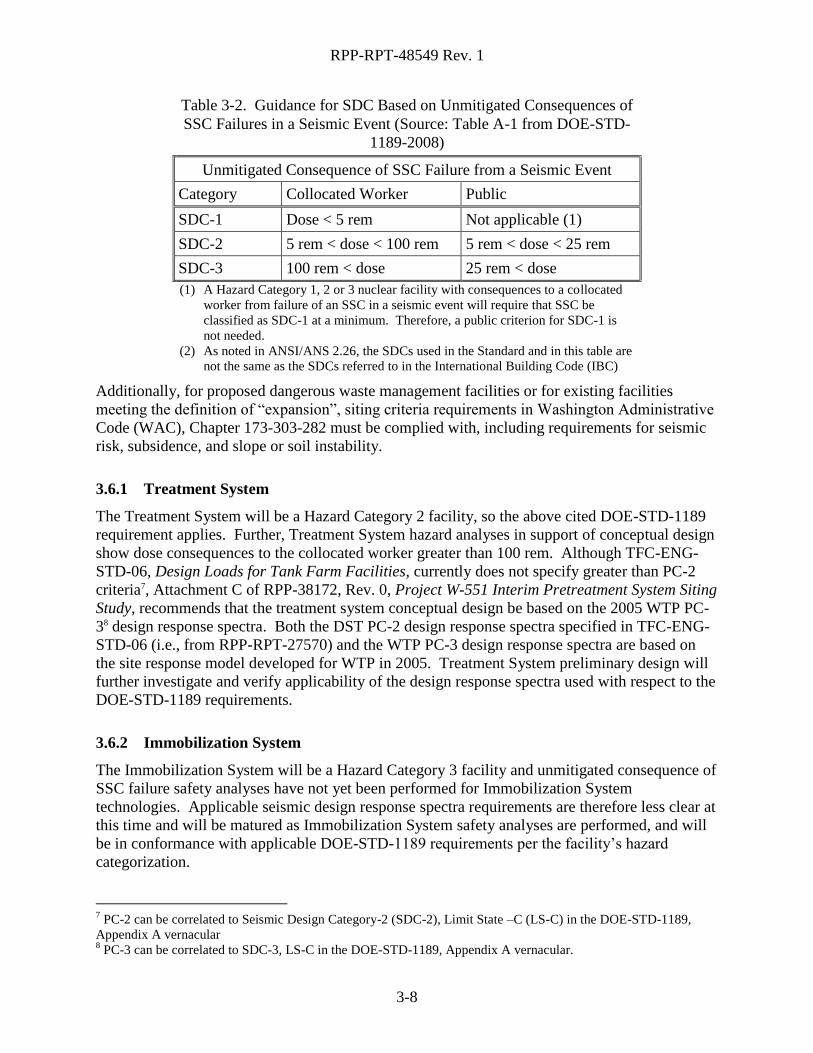
DOE-STD-1189-2008, Section A.1 states the following regarding methodologies for selecting a
Seismic Design Category (SDC):
In conceptual design, if there are no bases for defining seismic related Design Basis
Accidents (DBAs), Hazard Category 2 facility structural designs must default to
ANSI/ANS 2.26 SDC-3, Limit State D. If the hazards analysis conducted during
subsequent stages of design shows that unmitigated consequences are less than the
threshold criteria for SDC-3 shown in Table 3-2 below, then this may be reflected in the
evolving design stages.
6 NFPA 101®, Life Safety Code is a registered trademark of the National Fire Protection Association, Quincy,
Massachusetts, USA.
RPP-RPT-48549 Rev. 1
3-8
Table 3-2. Guidance for SDC Based on Unmitigated Consequences of
SSC Failures in a Seismic Event (Source: Table A-1 from DOE-STD-
1189-2008)
Unmitigated Consequence of SSC Failure from a Seismic Event
Category Collocated Worker Public
SDC-1 Dose < 5 rem Not applicable (1)
SDC-2 5 rem < dose < 100 rem 5 rem < dose < 25 rem
SDC-3 100 rem < dose 25 rem < dose
(1) A Hazard Category 1, 2 or 3 nuclear facility with consequences to a collocated
worker from failure of an SSC in a seismic event will require that SSC be
classified as SDC-1 at a minimum. Therefore, a public criterion for SDC-1 is
not needed.
(2) As noted in ANSI/ANS 2.26, the SDCs used in the Standard and in this table are
not the same as the SDCs referred to in the International Building Code (IBC)
Additionally, for proposed dangerous waste management facilities or for existing facilities
meeting the definition of “expansion”, siting criteria requirements in Washington Administrative
Code (WAC), Chapter 173-303-282 must be complied with, including requirements for seismic
risk, subsidence, and slope or soil instability.
3.6.1 Treatment System
The Treatment System will be a Hazard Category 2 facility, so the above cited DOE-STD-1189
requirement applies. Further, Treatment System hazard analyses in support of conceptual design
show dose consequences to the collocated worker greater than 100 rem. Although TFC-ENG-
STD-06, Design Loads for Tank Farm Facilities, currently does not specify greater than PC-2
criteria7, Attachment C of RPP-38172, Rev. 0, Project W-551 Interim Pretreatment System Siting
Study, recommends that the treatment system conceptual design be based on the 2005 WTP PC-
38 design response spectra. Both the DST PC-2 design response spectra specified in TFC-ENG-
STD-06 (i.e., from RPP-RPT-27570) and the WTP PC-3 design response spectra are based on
the site response model developed for WTP in 2005. Treatment System preliminary design will
further investigate and verify applicability of the design response spectra used with respect to the
DOE-STD-1189 requirements.
3.6.2 Immobilization System
The Immobilization System will be a Hazard Category 3 facility and unmitigated consequence of
SSC failure safety analyses have not yet been performed for Immobilization System
technologies. Applicable seismic design response spectra requirements are therefore less clear at
this time and will be matured as Immobilization System safety analyses are performed, and will
be in conformance with applicable DOE-STD-1189 requirements per the facility’s hazard
categorization.
7 PC-2 can be correlated to Seismic Design Category-2 (SDC-2), Limit State –C (LS-C) in the DOE-STD-1189,
Appendix A vernacular 8 PC-3 can be correlated to SDC-3, LS-C in the DOE-STD-1189, Appendix A vernacular.
RPP-RPT-48549 Rev. 1
3-9
3.7 ENVIRONMENTAL AND PERMITS
The basic siting criteria elements for the Treatment System and Immobilization System include
compliance with WAC 173-303-282 and consideration of the surrounding land, air, water, plants
and animals, and precipitation.
National Environmental Policy Act (NEPA) requirements will also influence a site selection.
The NEPA process is intended to help public officials make decisions that are based on
understanding environmental consequences of proposed actions, and take actions that protect,
restore, and enhance the environment. Key factors influencing the NEPA evaluations are
construction impacts to critical habitats, wildlife, cultural resources, and previously contaminated
sites.
Note that many sites or plots of land large enough to support the Treatment System and
Immobilization System are currently undisturbed and have mature sage that require mitigation at
a 3:1 ratio and 8 to 15 years of resource commitments.
RPP-RPT-48549 Rev. 1
4-1
4.0 PRELIMINARY SCREENING
Preliminary screening of possible Treatment and Immobilization facilities sites was done at a
macro scale (i.e., the 200 Areas – East and West) and considered the possible combinations of
200-East Area and 200-West Area Treatment and Immobilization Facilities. The preliminary
screening was:
1. Independent of technology selection;
2. Based on system modeling results documented in SVF-2038, Rev. 0, “ST Location
Model Runs.xlsx”; and
3. The following preliminary screening criteria:
a. Treatment and Immobilization Systems locations must not require new DST-farm
waste storage capacity9;
b. Treatment and Immobilization Systems locations must not require new cross-site
transfer system transfer lines10
;
c. Treatment system locations should be supportive of the 2020 Vision of the WTP
Project Transition to Operations and be able to support WTP LAW Vitrification in
case of WTP Pretreatment Facility delays or outages11
.
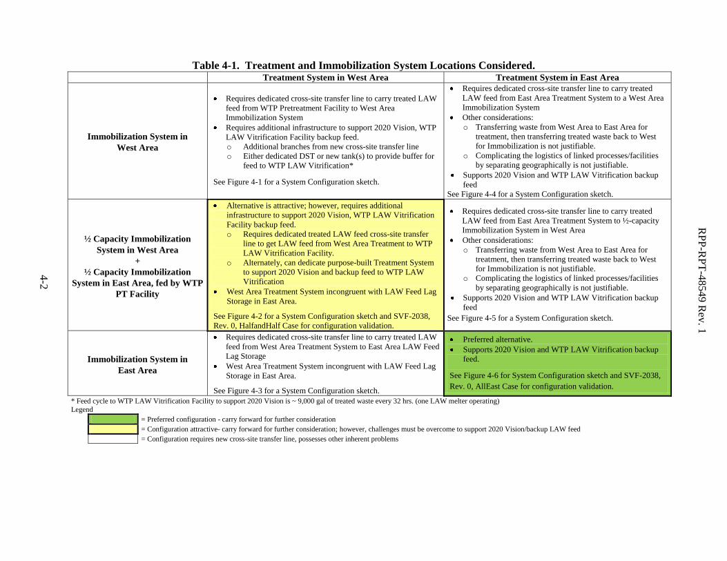
Table 4-1 summarizes the matrix of combinations considered, the combinations that were
screened out (no highlights) and the combinations that are to be taken forward for further
consideration (highlighted boxes) as a result of applying the above criteria. Combinations of
system locations that required either additional DST storage capacity or additional cross-site
transfer system lines to carry-out the primary Supplemental Treatment mission12
were eliminated
from consideration. Combinations that required additional infrastructure to support the 2020
Vision and/or provide backup feed for WTP LAW Vitrification were not eliminated from
consideration because these specific missions are not yet a formal part of the Supplemental
Treatment Program’s scope. Further, the 2020 Vision initiative may be best served by a
dedicated, more temporary installation in East Area due to its short duration and relatively low
capacity mission (e.g., SCIX installation in AP-farm).
System configurations that were not eliminated in the preliminary screening described above
were checked for validity via system plan modeling described and documented in spreadsheet
SVF-2038. These system model runs verified that Supplemental Treatment systems located as
described in Table 4-1, accomplish mission completion milestones and that nothing inherent
about their location precludes these system configurations for further consideration.
9 New DST storage capacity increases project costs ~ $150M per DST of waste storage capacity. Operational costs,
final clean-out and closure of new DSTs were not quantified, but considered to be substantial and prohibitive. 10
New cross-site transfer line replacement project cost is estimated ~ $82M (Result calculated from Project W-058
Title I project cost estimate [see WHC-SD-W058-DR-001, Rev. 0], escalated to FY ’11 dollars per “Escalation
Rate Assumptions for DOE Projects (November 27, 2009)”) 11
Note that this criterion is a “should” and was not used to screen-out options; 2020 Vision and providing backup
feed are not yet part of the Supplemental Treatment Program’s scope. Options that did not meet this criterion
were considered less desirable than those that do. Note that additional modifications to DST System utilization
would be needed for options that do not satisfy this criterion. 12
See Justification for Mission Need for the Hanford Tank Waste Supplemental Treatment Project, September
2010.
RP
P-R
PT
-48549 R
ev. 1
4-2
Table 4-1. Treatment and Immobilization System Locations Considered. Treatment System in West Area Treatment System in East Area
Immobilization System in
West Area
Requires dedicated cross-site transfer line to carry treated LAW
feed from WTP Pretreatment Facility to West Area
Immobilization System
Requires additional infrastructure to support 2020 Vision, WTP
LAW Vitrification Facility backup feed.
o Additional branches from new cross-site transfer line
o Either dedicated DST or new tank(s) to provide buffer for
feed to WTP LAW Vitrification*
See Figure 4-1 for a System Configuration sketch.
Requires dedicated cross-site transfer line to carry treated
LAW feed from East Area Treatment System to a West Area
Immobilization System
Other considerations:
o Transferring waste from West Area to East Area for
treatment, then transferring treated waste back to West
for Immobilization is not justifiable.
o Complicating the logistics of linked processes/facilities
by separating geographically is not justifiable.
Supports 2020 Vision and WTP LAW Vitrification backup
feed
See Figure 4-4 for a System Configuration sketch.
½ Capacity Immobilization
System in West Area
+
½ Capacity Immobilization
System in East Area, fed by WTP
PT Facility
Alternative is attractive; however, requires additional
infrastructure to support 2020 Vision, WTP LAW Vitrification
Facility backup feed.
o Requires dedicated treated LAW feed cross-site transfer
line to get LAW feed from West Area Treatment to WTP
LAW Vitrification Facility.
o Alternately, can dedicate purpose-built Treatment System
to support 2020 Vision and backup feed to WTP LAW
Vitrification
West Area Treatment System incongruent with LAW Feed Lag
Storage in East Area.
See Figure 4-2 for a System Configuration sketch and SVF-2038,
Rev. 0, HalfandHalf Case for configuration validation.
Requires dedicated cross-site transfer line to carry treated
LAW feed from East Area Treatment System to ½-capacity
Immobilization System in West Area
Other considerations:
o Transferring waste from West Area to East Area for
treatment, then transferring treated waste back to West
for Immobilization is not justifiable.
o Complicating the logistics of linked processes/facilities
by separating geographically is not justifiable.
Supports 2020 Vision and WTP LAW Vitrification backup
feed
See Figure 4-5 for a System Configuration sketch.
Immobilization System in
East Area
Requires dedicated cross-site transfer line to carry treated LAW
feed from West Area Treatment System to East Area LAW Feed
Lag Storage
West Area Treatment System incongruent with LAW Feed Lag
Storage in East Area.
See Figure 4-3 for a System Configuration sketch.
Preferred alternative.
Supports 2020 Vision and WTP LAW Vitrification backup
feed.
See Figure 4-6 for System Configuration sketch and SVF-2038,
Rev. 0, AllEast Case for configuration validation.
* Feed cycle to WTP LAW Vitrification Facility to support 2020 Vision is ~ 9,000 gal of treated waste every 32 hrs. (one LAW melter operating)
Legend
= Preferred configuration - carry forward for further consideration
= Configuration attractive- carry forward for further consideration; however, challenges must be overcome to support 2020 Vision/backup LAW feed
= Configuration requires new cross-site transfer line, possesses other inherent problems
RP
P-2
0499, R
ev. A
RP
P-R
PT
-48549 R
ev. 1
4-3
Figure 4-1. Supplemental Treatment Configuration: Immobilization System in West Area with Treatment System in West Area
SY-farm
AN-farm
Other East DSTs
Treatment
System
(In-tank or
Near tank)
Immobilization
System
WTP
Pretreatment
Facility
WTP LAW
Vitrification
Facility
Waste Feed to WTP
Treated LAW Feed (New cross-site transfer line)
DST Supernatant
LAW, HLW Transfers (Existing cross-site lines)
Treated LAW Feed
DST-DST Waste Transfers
200 East Area200 West Area
Treated LAW Feed
to Support 2020 Vision,
Backup Feed
Existing Facilities & Infrastructure
New Facilities & Infrastructure
Additional Infrastructure required to support 2020
Vision, Backup Feed to WTP LAW Vit Facility
Treated LAW Feed
To HLW Vit
Dedicated East DST for Buffer
(To be decided)
Treated LAW Feed
to Support 2020 Vision,
Backup Feed
RP
P-2
0499, R
ev. A
RP
P-R
PT
-48549 R
ev. 1
4-4
Figure 4-2. Supplemental Treatment Configuration: ½-capacity Immobilization System in West Area fed by Treatment System
in West Area + ½-capacity Immobilization System in East Area fed by WTP Pretreatment Facility
SY-farm
AN-farm
Other East DSTs
Treatment
System
(In-tank or
Near tank)
½-Capacity
Immobilization
System
WTP
Pretreatment
Facility
WTP LAW
Vitrification
Facility
Waste Feed to WTP
DST Supernatant
LAW, HLW Transfers (Existing cross-site lines)
Treated LAW Feed to Support 2020 Vision, Backup Feed
Treated LAW Feed
DST-DST Waste Transfers
200 East Area200 West Area
Treated LAW Feed
to Support 2020 Vision,
Backup Feed
Existing Facilities & Infrastructure
New Facilities & Infrastructure
Additional Infrastructure required to support 2020
Vision, Backup Feed to WTP LAW Vit Facility
½-Capacity
Immobilization
System
Treated LAWLAW Feed
Lag Storage†
Treated LAW Feed
Treated LAW Feed
To HLW Vit
† Shown separately because dislocated from Treatment System
RP
P-2
0499, R
ev. A
RP
P-R
PT
-48549 R
ev. 1
4-5
Figure 4-3. Supplemental Treatment Configuration: Immobilization System in East Area with Treatment System in West Area
SY-farm
AN-farm
Other East DSTs
Treatment
System
(In-tank or
Near tank)
WTP
Pretreatment
Facility
WTP LAW
Vitrification
Facility
Waste Feed to WTP
DST Supernatant
LAW, HLW Transfers (Existing cross-site lines)
DST-DST Waste Transfers
200 East Area200 West Area
Treated LAW Feed
to Support 2020 Vision,
Backup Feed
Existing Facilities & Infrastructure
New Facilities & Infrastructure
Additional Infrastructure required to support 2020
Vision, Backup Feed to WTP LAW Vit Facility
Immobilization
System
Treated LAWLAW Feed
Lag Storage†
Treated LAW Feed
Treated LAW (New cross-site line)
Also supports Feed for 2020 Vision,
Backup Feed
To HLW Vit
Treated LAW Feed
† Shown separately because dislocated from Treatment System
RP
P-2
0499, R
ev. A
RP
P-R
PT
-48549 R
ev. 1
4-6
Figure 4-4. Supplemental Treatment Configuration: Immobilization System in West Area with Treatment System in East Area
SY-farm
AN-farm
Other East DSTs
Treatment
System
(In-tank or
Near tank)
Immobilization
System
WTP
Pretreatment
Facility
WTP LAW
Vitrification
Facility
Waste Feed to WTPDST Supernatant
LAW, HLW Transfers (Existing cross-site lines)
Treated LAW Feed (New cross-site transfer line)
DST-DST Waste Transfers
200 East Area200 West Area
Treated LAW Feed
to Support 2020 Vision,
Backup Feed
Existing Facilities & Infrastructure
New Facilities & Infrastructure
Additional Infrastructure required to support 2020
Vision, Backup Feed to WTP LAW Vit Facility
Treated LAW Feed
To HLW Vit
Treated LAW Feed
RP
P-2
0499, R
ev. A
RP
P-R
PT
-48549 R
ev. 1
4-7
Figure 4-5. Supplemental Treatment Configuration: ½-capacity Immobilization System in West Area fed by Treatment System
in East Area + ½-capacity Immobilization System in East Area fed by WTP Pretreatment Facility.
SY-farm
AN-farm
Other East DSTs
Treatment
System
(In-tank or
Near tank)
½-Capacity
Immobilization
System
WTP
Pretreatment
Facility
WTP LAW
Vitrification
Facility
Waste Feed to WTP
LAW, HLW Transfers (Existing cross-site lines)
Treated LAW Feed (New cross-site transfer line)
DST-DST Waste Transfers
200 East Area200 West Area
Treated LAW Feed
to Support 2020 Vision,
Backup Feed
Treated LAW
Existing Facilities & Infrastructure
New Facilities & Infrastructure
Additional Infrastructure required to support 2020
Vision, Backup Feed to WTP LAW Vit Facility
½-Capacity
Immobilization
System
Treated LAW
DST Supernatant
Treated LAW Feed
To HLW Vit
Waste Feed to WTP
RP
P-2
0499, R
ev. A
RP
P-R
PT
-48549 R
ev. 1
4-8
Figure 4-6. Supplemental Treatment Configuration: Immobilization System in East Area with Treatment System in East Area.
SY-farm
AN-farm
Other East DSTs
Treatment
System
(In-tank or
Near tank)
WTP
Pretreatment
Facility
WTP LAW
Vitrification
Facility
DST Supernatant
LAW, HLW Transfers (Existing cross-site lines)
DST-DST Waste Transfers
200 East Area200 West Area
Treated LAW Feed
to Support 2020 Vision,
Backup Feed
Existing Facilities & Infrastructure
New Facilities & Infrastructure
Additional Infrastructure required to support 2020
Vision, Backup Feed to WTP LAW Vit Facility
Immobilization
System
Treated LAW
Treated LAW Feed
To HLW Vit
Waste Feed to WTP
Treated LAW Feed
RPP-RPT-48549 Rev. 1
4-9
4-9
Note from the Supplemental Treatment Systems configuration diagrams above that LAW
Feed Lag Storage is required to be located away from the Treatment System’s physical
boundary when the Treatment System is located in West Area and the Immobilization
System (or a portion of the Immobilization System’s capacity) is located in East Area (see
Figures 4-2 and 4-3). Although operation can be accomplished with this configuration, it is
not the most desirable for integrated operation of dependent facilities. LAW Feed Lag
Storage, in addition to supporting feed management and throughput demands of the
Immobilization System, also allow for LAW sampling prior to LAW transfer to the
Immobilization Facility. Having the LAW Feed Lag Storage tanks as a separate entity/system
also serves to ensure that the Immobilization Facility remains a Hazard Category 3 facility.
Further, alternatives analysis supporting the Treatment System’s Conceptual Design
concluded that LAW Feed Lag Storage should be separate from the Treatment System as
well. Therefore, siting considerations must account for the LAW Feed Lag Storage tanks to
be separate from the Treatment and Immobilization Systems’ footprint. Figure 4-7 provides
an estimate of the footprint and depth of the LAW Feed Lag Storage tanks made from
information contained in RPP-RPT-48117, Rev. 0, Supplemental Treatment Technical
Support Pre-Conceptual Candidate Technical Descriptions (see Figures 8-2 through 8-12
and supporting information therein). Note that this estimate represents a worst case footprint
of the LAW Feed Lag Storage Tanks Facility due to Treatment System throughput
requirement refinement since RPP-RPT-48117, Rev. 0 release.
RPP-RPT-48549 Rev. 1
4-10
4-1
0
Figure 4-7. LAW Feed Lag Storage Tanks Facility Footprint.
LAW Product
Tank 82,000 gal
LAW Product
Tank 82,000 gal
LAW Product
Tank 82,000 gal
LAW Product
Tank 82,000 gal
Valve Vault
LAW Product
Tank 82,000 galLAW Product
Tank 82,000 gal
Pump Pump Pump
Pump Pump Pump
27 ft
8 ft
3 ft
80 ft
27 ft
99 ft
6 ft
A
A
LAW Product Tank LAW Product TankValve
Vault
40 ft
Section A - A
The below sections discuss the advantages and disadvantages of the viable system configurations
identified in Table 4-1 (highlighted boxes).
4.1 SPLIT CAPACITY IMMOBILIZATION SYSTEM IN WEST
AND EAST AREAS
Advantages and disadvantages of the “½-Capacity Immobilization System in West Area fed
by West Area Treatment System with a ½-Capacity Immobilization System in East Area, fed
by WTP Pretreatment Facility” system configuration (see Figure 4-2) are outlined below:
Advantages
a. Supplemental Treatment Systems operate autonomously.
Supplemental Treatment Systems receive feed from their respective Areas.
200 West Area Systems are fed from the West Area tank waste.
200 East Area Systems are fed from East Area tank waste.
RPP-RPT-48549 Rev. 1
4-11
4-1
1
Eliminates single-point failure potential; built-in diversity.
Major failure or bottleneck in East Area tank farms or treatment facilities
does not necessarily stop or hinder waste processing in West Area; likewise,
failure in West Area does not necessarily hinder East Area operations.
200 West Area Systems are neither subject to nor do they contribute to 200 East
Area congestion.
Bulk materials deliveries
Facility maintenance
b. Construction activities are not encumbered by 200-East Area congestion.
c. Facility schedules are not necessarily coupled and can be independent of one
another.
d. Construction, training and start-up can be staggered and efficiencies gained.
e. Cross-site transfers of LAW supernatant are not required.
Subsequent transfers of LAW supernatant within East Area are similarly
eliminated.
f. Split facilities can lead to flexibility on selection of an immobilization technology.
Disadvantages
a. Immobilized product and secondary solid waste must be shipped from the West
Area Facilities to the East Area (i.e., Integrated Disposal Facility [IDF]).
b. Secondary liquid waste, if any, must be transferred from the West Area Facilities to
the East Area (i.e., ETF).
c. Remediation of SY-103 (Group A tank) is required prior to operation.
d. Additional infrastructure is required to support 2020 Vision, WTP LAW
Vitrification Facility backup feed13.
Dedicated treated LAW feed cross-site transfer line (or other means) to get
treated LAW from Treatment System to WTP LAW Vitrification Facility.
e. Coupled Treatment System – LAW Feed Lag Storage operations separated by
greater than 6.5 miles.
4.2 TREATMENT SYSTEM AND IMMOBILIZATION SYSTEM
LOCATED IN EAST AREA
Advantages and disadvantages of this system configuration (see Figure 4-6) are outlined
below.
Advantages
a. Impact on DST System functionality is less – using 1 of 25 DSTs in East Area
instead of 1 of 3 DSTs in West Area.
b. Immobilized product and secondary solid waste transport is shorter – East Area
Supplemental Treatment Systems to IDF (East Area).
c. Secondary liquid waste transport is simpler – East Area Supplemental Treatment
Systems to ETF (East Area).
d. Supports 2020 vision and WTP LAW Vitrification backup feed without major
infrastructure additions.
13
Alternatively, a purpose-built Treatment System can be dedicated to support 2020 Vision and backup feed to
WTP LAW Vitrification Facility.
RPP-RPT-48549 Rev. 1
4-12
4-1
2
e. Treating East Area DST supernatant will free-up much needed DST space in East
Area.
f. One facility (or multiple adjacent co-located facilities) and one construction site (or
multiple adjacent co-located construction sites) to manage.
Disadvantages (Inverse of Section 4.1 Advantages)
a. Susceptible to single point failure and resulting major loss of production. Several
possible major failure modes:
Single immobilization facility failure.
Treatment System failure, which leads to only ~ ½ feed availability for
Immobilization System.
Cross-site transfer system failure
Leads to diminished feed blending, which increases immobilized LAW
product volume.
Possibility of diminished feed availability.
b. WTP PT Facility downtime/delays leads to only ~ ½ feed availability for
Immobilization System – necessitates turndown on Immobilization System.
c. East Area congestion with bulk materials delivery, construction activities,
operations and maintenance activities.
RPP-RPT-48549 Rev. 1
5-1
5.0 AVAILIBILITY OF SITES
The preliminary screening of possible locations in the 200 Areas yielded the following viable
options for further consideration:
1. A split capacity Immobilization System: one located in East Area, the other in West Area.
It is envisioned that the West Area Immobilization System would be fed by Treatment
System dedicated to West Area Immobilization, while the East Area Immobilization
System could be fed by the WTP PT Facility (see Figure 4-2).
2. An Immobilization System located in East Area, fed treated LAW by both a Treatment
System and the WTP PT facility (see Figure 4-6).
Due to the location of WTP PT Facility and the fact that this facility provides approximately half
the treated LAW feed to the Immobilization System, a clear need for East Area sites emerged
from the preliminary screening. East Area sites also better support the secondary missions of the
Treatment System.
Note also that the 2nd
LAW Facility option for immobilization requires a facility footprint, driven
by needed support facilities (see Table 3-1), that is approximately five times the next nearest
technology in total foot print demand. The most logical location for a 2nd
LAW Facility is in
East Area on the WTP site where a similar, smaller scale facility using the same processes and
types of support facilities will be in operation. Also, space has been allocated for a 2nd
LAW
facility and its support systems on the WTP site (see Figure A-7). Site locations for a 2nd
LAW
facility outside the WTP boundary will not be sought as part of this site evaluation14.
The search for available sites in 200 East Area and 200 West Area was conducted with full
awareness of MSA Facilities and Property Management, and concentrated on areas that provided
~ 10 acres15 of land in close proximity of the sources of feed for the Treatment System and
Immobilization System. Note that this amount of land is bounding and will allow for co-location
of the Treatment System with the Immobilization Systems.
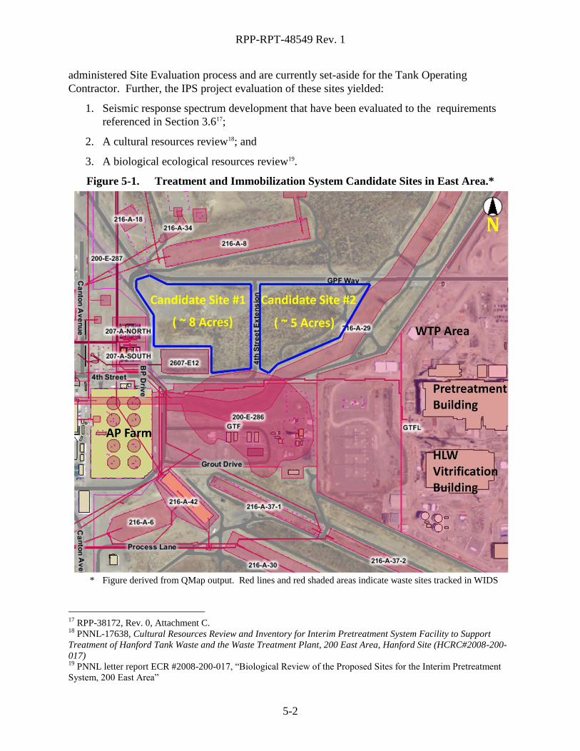
5.1 CANDIDATE SITES IN 200 EAST AREA
A previous study performed for the IPS project, a predecessor to the Treatment System project,
yielded suitable candidate sites in 200 East Area appropriate for IPS use (see Figure 5-1)16.
These candidate sites also satisfy the criteria for consideration for the Treatment System and
Immobilization System use– close proximity to DST waste feed, pretreated LAW from WTP PT
and has a combined area of ~ 13 acres. These sites have gone through the formal MSA
14
A preliminary evaluation of space allocated to 2nd
LAW by WTP shows that this allocation may be inadequate;
however, expansion into adjacent temporary construction parking and spoils areas is preferred to breaking new
ground for an autonomous 2nd
LAW facility outside the WTP site boundary. The next best option is expanding the
current footprint of the WTP site. 15
From Table 3-1: Worst case Treatment System footprint ( 43,500 ft2) + worst case Immobilization System
footprint (not including 2nd
LAW) (165,000 ft2) = 208,500 ft
2 (< 5 acres)
16 RPP-38172, Rev. 0, Project W-551 Interim Pretreatment System (IPS) Siting Study
RPP-RPT-48549 Rev. 1
5-2
administered Site Evaluation process and are currently set-aside for the Tank Operating
Contractor. Further, the IPS project evaluation of these sites yielded:
1. Seismic response spectrum development that have been evaluated to the requirements
referenced in Section 3.617;
2. A cultural resources review18; and
3. A biological ecological resources review19.
Figure 5-1. Treatment and Immobilization System Candidate Sites in East Area.*
* Figure derived from QMap output. Red lines and red shaded areas indicate waste sites tracked in WIDS
17
RPP-38172, Rev. 0, Attachment C. 18
PNNL-17638, Cultural Resources Review and Inventory for Interim Pretreatment System Facility to Support
Treatment of Hanford Tank Waste and the Waste Treatment Plant, 200 East Area, Hanford Site (HCRC#2008-200-
017) 19
PNNL letter report ECR #2008-200-017, “Biological Review of the Proposed Sites for the Interim Pretreatment
System, 200 East Area”
RPP-RPT-48549 Rev. 1
5-3
Appendix B contains a photo log of Candidate Site #1 and #2 site walk down results obtained in
April of 2008; a brief walk down in September 2010 verified no major changes to the sites had
occurred. Note that all salient features of these sites are documented in RPP-38172, Project W-
551 Interim Pretreatment System (IPS) Siting Study.
5.1.1 East Area In-tank Treatment System Location
Twenty-five DSTs are arranged in five different tank farms in 200 East Area; however, the most
practical option for in-tank treatment in 200 East is in the 241-AP tank farm. East Area tank
farm utilization is explained below:
1. AN tank farm will be used as the HLW sludge staging farm for waste feed delivery
(WFD) to WTP (see RPP-40149, Rev. 1, Integrated Waste Feed Delivery Plan). The 42
inch risers in AN-farm tanks will be occupied by submersible mixer pumps (SMP)
employed for sludge tank waste mixing.
2. AY/AZ tank farms are similarly used as HLW sludge tanks early in the WFD mission
(RPP-40149, Rev. 1). Construction and deployment of an in-tank Treatment System
directly overlaps HLW sludge waste feed deliveries out of these tanks. Similar to AN-
farm, the available large risers in AY/AZ tanks will be occupied by SMPs.
3. AW-tank farm requires a tank-by tank analysis:
a. AW-101 is a Group A waste tank; as such, it requires remediation prior to
deployment of an in-tank Treatment System. This activity requires DST waste
storage space (~ 2 x initial AW-101 tank volume). DST space is at a premium prior
to WTP or other waste treatment start-up. Therefore, AW-101 is not a good
candidate for in-tank Treatment System deployment.
b. AW-102 is the 242-A Evaporator feed tank. Significant evaporation campaigns are
on-going throughout the WFD mission.
c. AW-103, -104 and -105 are HLW sludge tanks. These tanks are not good candidates
for the same reasons AY/AZ tanks and AN-tanks are not good candidates for in-tank
Treatment System deployment.
d. AW-106 is the only possible tank in AW-farm that is a candidate for in-tank
Treatment System deployment. Since AW-106 is the only viable tank in the farm,
significant tank modification would be needed to deploy an in-tank Treatment System
in AW-106 – new risers would need to be installed.
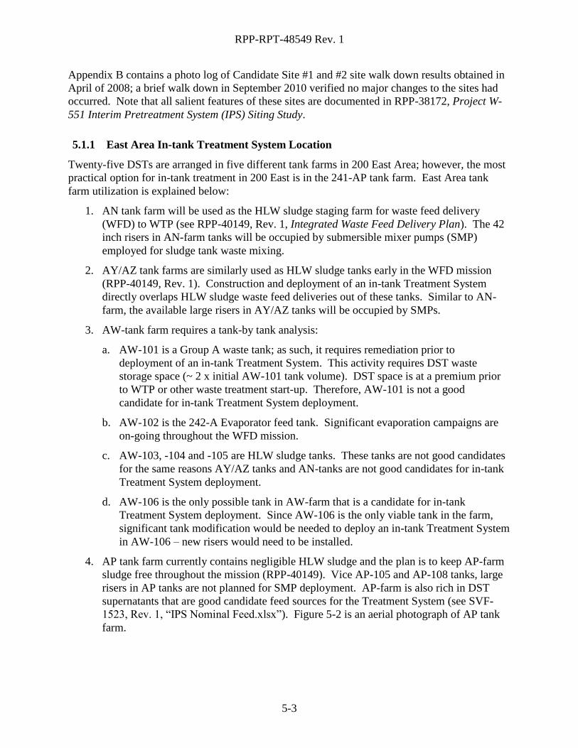
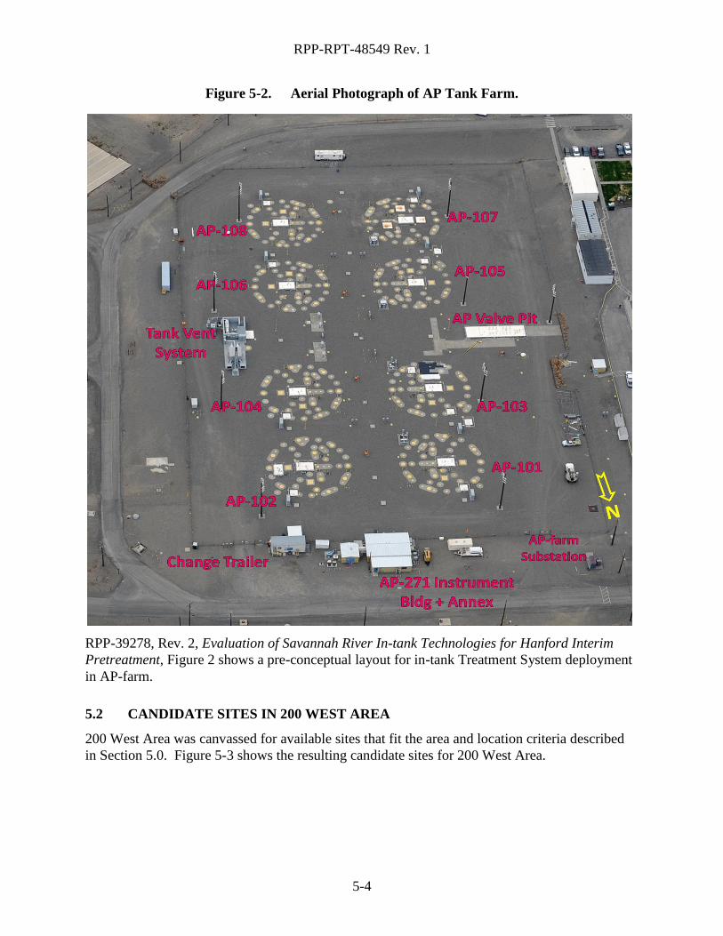
4. AP tank farm currently contains negligible HLW sludge and the plan is to keep AP-farm
sludge free throughout the mission (RPP-40149). Vice AP-105 and AP-108 tanks, large
risers in AP tanks are not planned for SMP deployment. AP-farm is also rich in DST
supernatants that are good candidate feed sources for the Treatment System (see SVF-
1523, Rev. 1, “IPS Nominal Feed.xlsx”). Figure 5-2 is an aerial photograph of AP tank
farm.
RPP-RPT-48549 Rev. 1
5-4
Figure 5-2. Aerial Photograph of AP Tank Farm.
RPP-39278, Rev. 2, Evaluation of Savannah River In-tank Technologies for Hanford Interim
Pretreatment, Figure 2 shows a pre-conceptual layout for in-tank Treatment System deployment
in AP-farm.
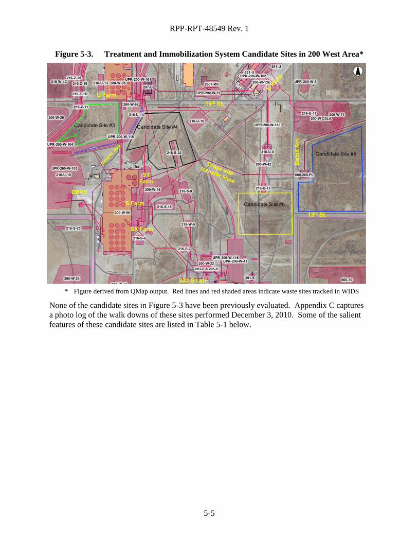
5.2 CANDIDATE SITES IN 200 WEST AREA
200 West Area was canvassed for available sites that fit the area and location criteria described
in Section 5.0. Figure 5-3 shows the resulting candidate sites for 200 West Area.
RPP-RPT-48549 Rev. 1
5-5
Figure 5-3. Treatment and Immobilization System Candidate Sites in 200 West Area*
* Figure derived from QMap output. Red lines and red shaded areas indicate waste sites tracked in WIDS
None of the candidate sites in Figure 5-3 have been previously evaluated. Appendix C captures
a photo log of the walk downs of these sites performed December 3, 2010. Some of the salient
features of these candidate sites are listed in Table 5-1 below.
5-6
5-6
RP
P-R
PT
-48549 R
ev. 1
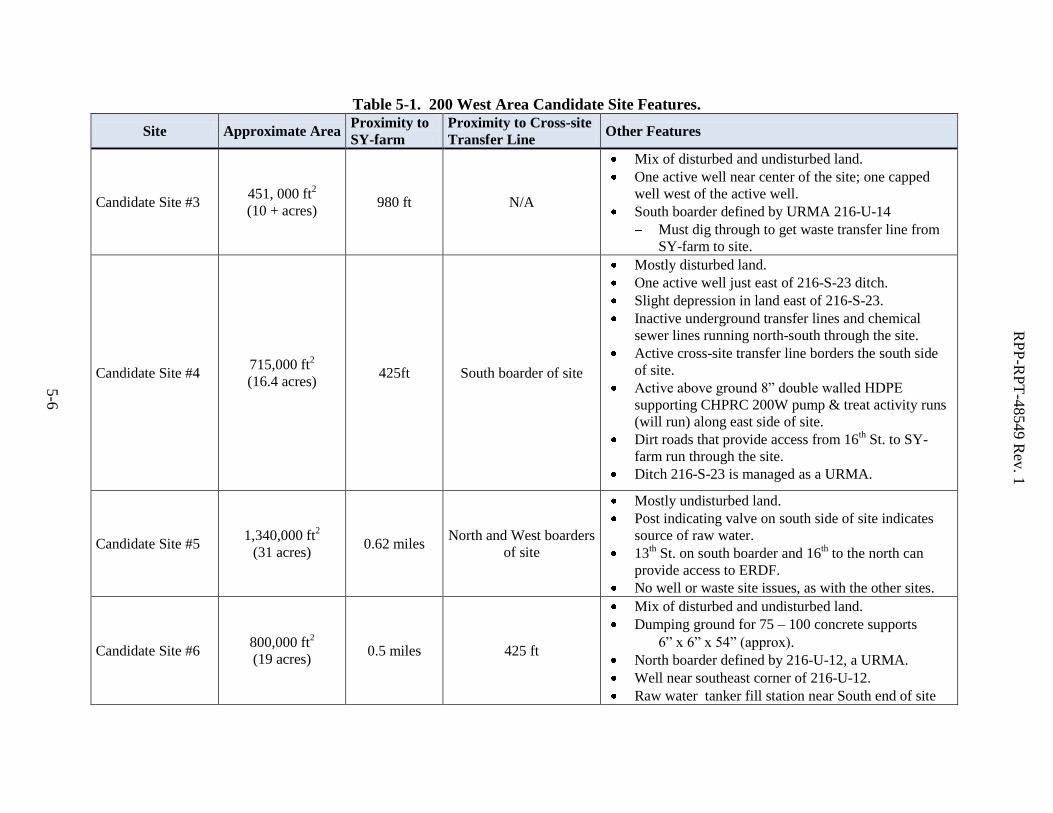
Table 5-1. 200 West Area Candidate Site Features.
Site Approximate Area Proximity to
SY-farm
Proximity to Cross-site
Transfer Line Other Features
Candidate Site #3 451, 000 ft
2
(10 + acres) 980 ft N/A
Mix of disturbed and undisturbed land.
One active well near center of the site; one capped
well west of the active well.
South boarder defined by URMA 216-U-14
Must dig through to get waste transfer line from
SY-farm to site.
Candidate Site #4 715,000 ft
2
(16.4 acres) 425ft South boarder of site
Mostly disturbed land.
One active well just east of 216-S-23 ditch.
Slight depression in land east of 216-S-23.
Inactive underground transfer lines and chemical
sewer lines running north-south through the site.
Active cross-site transfer line borders the south side
of site.
Active above ground 8” double walled HDPE
supporting CHPRC 200W pump & treat activity runs
(will run) along east side of site.
Dirt roads that provide access from 16th St. to SY-
farm run through the site.
Ditch 216-S-23 is managed as a URMA.
Candidate Site #5 1,340,000 ft
2
(31 acres) 0.62 miles
North and West boarders
of site
Mostly undisturbed land.
Post indicating valve on south side of site indicates
source of raw water.
13th St. on south boarder and 16
th to the north can
provide access to ERDF.
No well or waste site issues, as with the other sites.
Candidate Site #6 800,000 ft
2
(19 acres) 0.5 miles 425 ft
Mix of disturbed and undisturbed land.
Dumping ground for 75 – 100 concrete supports
6” x 6” x 54” (approx).
North boarder defined by 216-U-12, a URMA.
Well near southeast corner of 216-U-12.
Raw water tanker fill station near South end of site
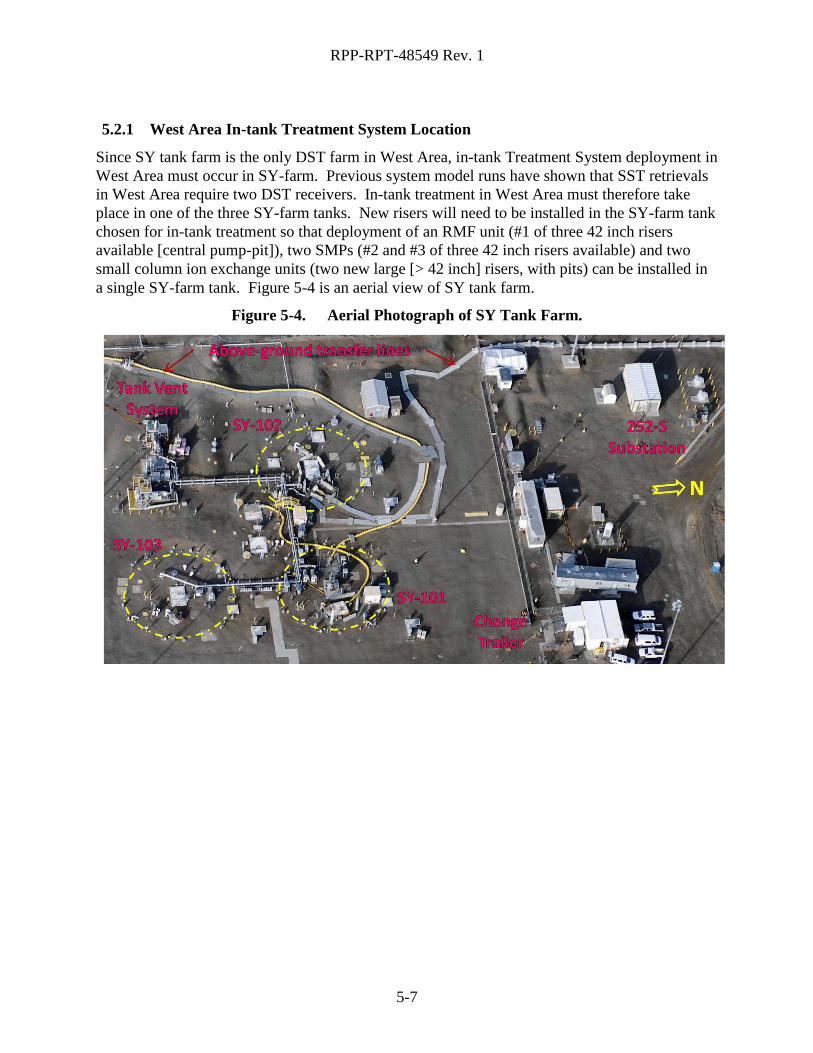
RPP-RPT-48549 Rev. 1
5-7
5-7
5.2.1 West Area In-tank Treatment System Location
Since SY tank farm is the only DST farm in West Area, in-tank Treatment System deployment in
West Area must occur in SY-farm. Previous system model runs have shown that SST retrievals
in West Area require two DST receivers. In-tank treatment in West Area must therefore take
place in one of the three SY-farm tanks. New risers will need to be installed in the SY-farm tank
chosen for in-tank treatment so that deployment of an RMF unit (#1 of three 42 inch risers
available [central pump-pit]), two SMPs (#2 and #3 of three 42 inch risers available) and two
small column ion exchange units (two new large [> 42 inch] risers, with pits) can be installed in
a single SY-farm tank. Figure 5-4 is an aerial view of SY tank farm.
Figure 5-4. Aerial Photograph of SY Tank Farm.
RPP-RPT-48549 Rev. 1
6-1
6-1
6.0 FORMAL EVALUATION OF SITES
A formal evaluation of the sites presented in Section 5.0 will not be performed prior to
immobilization technology down-select. Technology selection will drive the needs of the site,
particularly for the Immobilization System. Large variability in factors discriminating suitable
sites exist depending on selection of the immobilization technology. For example, if the
immobilization technology chosen is Bulk Vitrification, upwards of 15 MVA of power will be
required. It is likely that this amount of power will require a direct interface with the Bonneville
Power Administration’s (BPA) 230 kV lines instead of an interface with existing 13.8 kV site
service provided out of the 251-W Substation. Other immobilization technologies will require
less than one tenth this amount of power20.
The following sections serve as placeholders and contain some sample information for the
formal site evaluation to be performed subsequent to immobilization technology selection.
6.1 EVALUATION CRITERIA AND WEIGHTING
Requirements and system characteristics from Section 3.0, as well as other attributes or criteria
important to the Treatment System and Immobilization System construction and operation (e.g.,
integration with WTP and tank farm operations) that affect system siting have been identified
and are described in the following sections.
6.1.1 Description of Criteria Considered
The following example criteria were developed to provide a starting point and example criteria to
be used when evaluating candidate sites. Subsequent to technology selection, these criteria must
be re-defined.
20
Note that “other immobilization technologies” in the context of this sentence does not include 2nd
LAW
Vitrification; the area set-aside within the WTP complex would be chosen to host 2nd
LAW Vitrification. The WTP
site is already connected to the BPA’s 230 kV lines. The WTP 13.8 kV substation and BPA’s allocation of power to
the WTP site will need upgrading if 2nd
LAW Vitrification is the chosen immobilization technology.
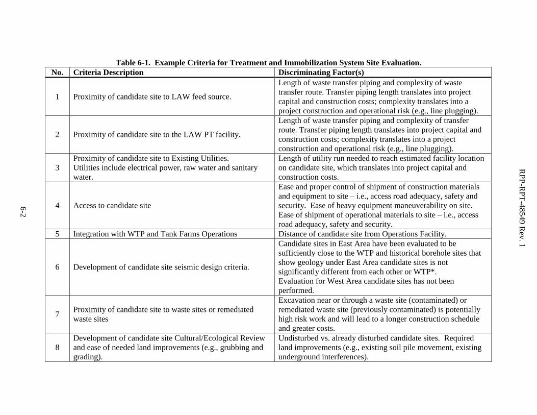
6-2
RP
P-R
PT
-48549 R
ev. 1
6-2
Table 6-1. Example Criteria for Treatment and Immobilization System Site Evaluation.
No. Criteria Description Discriminating Factor(s)
1 Proximity of candidate site to LAW feed source.
Length of waste transfer piping and complexity of waste
transfer route. Transfer piping length translates into project
capital and construction costs; complexity translates into a
project construction and operational risk (e.g., line plugging).
2 Proximity of candidate site to the LAW PT facility.
Length of waste transfer piping and complexity of transfer
route. Transfer piping length translates into project capital and
construction costs; complexity translates into a project
construction and operational risk (e.g., line plugging).
3
Proximity of candidate site to Existing Utilities.
Utilities include electrical power, raw water and sanitary
water.
Length of utility run needed to reach estimated facility location
on candidate site, which translates into project capital and
construction costs.
4 Access to candidate site
Ease and proper control of shipment of construction materials
and equipment to site – i.e., access road adequacy, safety and
security. Ease of heavy equipment maneuverability on site.
Ease of shipment of operational materials to site – i.e., access
road adequacy, safety and security.
5 Integration with WTP and Tank Farms Operations Distance of candidate site from Operations Facility.
6 Development of candidate site seismic design criteria.
Candidate sites in East Area have been evaluated to be
sufficiently close to the WTP and historical borehole sites that
show geology under East Area candidate sites is not
significantly different from each other or WTP*.
Evaluation for West Area candidate sites has not been
performed.
7 Proximity of candidate site to waste sites or remediated
waste sites
Excavation near or through a waste site (contaminated) or
remediated waste site (previously contaminated) is potentially
high risk work and will lead to a longer construction schedule
and greater costs.
8
Development of candidate site Cultural/Ecological Review
and ease of needed land improvements (e.g., grubbing and
grading).
Undisturbed vs. already disturbed candidate sites. Required
land improvements (e.g., existing soil pile movement, existing
underground interferences).
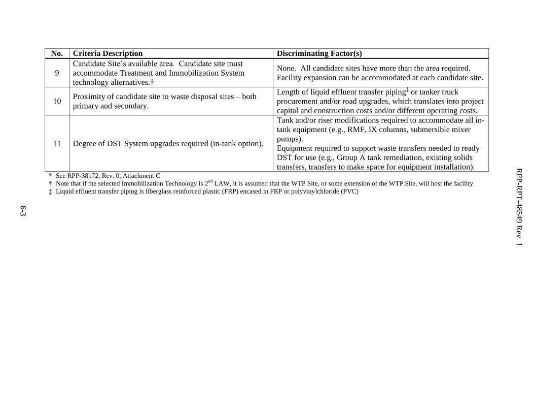
6-3
RP
P-R
PT
-48549 R
ev. 1
6-3
No. Criteria Description Discriminating Factor(s)
9
Candidate Site’s available area. Candidate site must
accommodate Treatment and Immobilization System
technology alternatives.†
None. All candidate sites have more than the area required.
Facility expansion can be accommodated at each candidate site.
10 Proximity of candidate site to waste disposal sites – both
primary and secondary.
Length of liquid effluent transfer piping‡ or tanker truck
procurement and/or road upgrades, which translates into project
capital and construction costs and/or different operating costs.
11 Degree of DST System upgrades required (in-tank option).
Tank and/or riser modifications required to accommodate all in-
tank equipment (e.g., RMF, IX columns, submersible mixer
pumps).
Equipment required to support waste transfers needed to ready
DST for use (e.g., Group A tank remediation, existing solids
transfers, transfers to make space for equipment installation). * See RPP-38172, Rev. 0, Attachment C
† Note that if the selected Immobilization Technology is 2nd
LAW, it is assumed that the WTP Site, or some extension of the WTP Site, will host the facility.
‡ Liquid effluent transfer piping is fiberglass reinforced plastic (FRP) encased in FRP or polyvinylchloride (PVC)
RPP-RPT-48549 Rev. 1
6-4
6-4
6.1.2 Criteria Weighting
Criteria described in Section 6.1.1 are weighted relative to one another based on:
1. Construction and material costs associated with each;
2. Operational costs; or
3. A qualitative relative importance.
Quantitative costs associated with construction (direct project cost) or operations (overall
program cost) will be the preferred method of weighting. When a weighting value associated
with construction, material or operational cost cannot be assigned, a qualitative judgment of the
overall weighting of these criteria will be made. In instances where a criterion yields no
discriminating factors relative to the candidate sites, a weighting of zero percent will be assigned
(e.g., Criterion 7).
6.2 EVALUATION RESULTS
Formal evaluation of the sites will be performed post immobilization technology down-select.
RPP-RPT-48549 Rev. 1
7-1
7-1
7.0 CONCLUSIONS
Many aspects of the site selection are dependent on Immobilization System technology selection.
A definitive, formal evaluation and site selection will be made subsequent to an Immobilization
System technology selection (scheduled for Fiscal Year 2012).
Preliminary screening and qualitative site evaluation performed independent of technology
selection herein, showed a slight bias to locating the Treatment and Immobilization Systems in
East Area. Gross advantages include:
1. Proximity to feed sources – from both DSTs and WTP PT
Potential use of AP-farm DST for LAW feed lag storage
2. Supports other initiatives – e.g., 2020 Vision and backup feed to the WTP LAW
Facility.
3. Previous IPS project work eliminates uncertainties regarding site-specific requirements
such as seismic response design criteria and cultural resources review21.
4. In-tank treatment option has a higher potential of being able to use two DSTs, rather
than one.
5. If Immobilization System technology is 2nd
LAW, WTP site will host the 2nd
LAW
facility, and an East Area Treatment System will be “co-located”.
Design for the Treatment System will therefore be performed assuming the Treatment System
and Immobilization System are both located in East Area22. Further, Candidate Site #1 will be
reserved for any Near-tank Treatment System facilities required – i.e., a near tank facility or a
facility to include LAW feed lag storage – while Candidate Site #2 will be reserved for the
Immobilization System. If the conceptual design recommendation for the In-tank Treatment
System option is accepted, AP-farm will be utilized as the basis for the conceptual design. The
Treatment System design A-E will deliver only design solutions that do not preclude Treatment
System siting at one of the 200 West Area sites described herein.
21
Note that biological/ecological resource review conducted for Candidate Sites 1 and 2 has expired and would need
to be updated. 22
Note that Treatment System conceptual design activities started January 2011, approximately 12 months in
advance of the scheduled Immobilization System technology down select and start of conceptual design.
RPP-RPT-48549 Rev. 1
8-1
8-1
8.0 REFERENCES
ANSI/IEEE C2-2007, “National Electrical Safety Code”, American National Standards Institute,
New York, New York, 2002.
DOE/ORP-2003-02, Environmental Impact Statement for Retrieval, Treatment, and Disposal of
Tank Waste and Closure of the Single Shell Tanks at the Hanford Site, Richland WA,
Inventory and Source Term Data Package, Office of River Protection, Richland, WA.
DOE-STD-1189-2008, Integration of Safety into the Design Process, March 2008, US
Department of Energy, Washington DC.
Ecology, EPA, and DOE, 1989, Hanford Federal Facility Agreement and Consent Order, State
of Washington Department of Ecology, U.S. Environmental Protection Agency, and U.S.
Department of Energy, Olympia, Washington, as amended
NFPA 70, 2005, “National Electric Code”, National Fire Protection Association, Quincy, Mass.,
2005.
ORP-11242, 2010, River Protection Project System Plan, Rev 5, Washington River Protection
Solutions, Richland, Washington.
RPP-38172, 2008, Project W-551 interim Pretreatment System (IPS) Siting Study, Rev. 0,
Washington River Protection Solutions, Richland, Washington.
RPP-39278, 2010, Evaluation of Savannah River In-tank Technologies for Hanford Interim
Pretreatment, Rev. 2, Washington River Protection Solutions, Richland, Washington.
RPP-40149, 2010, Integrated Waste Feed Delivery Plan, Rev. 1, Washington River Protection
Solutions LLC, Richland, Washington.
RPP-46811, 2010, Functions and Requirements: 200 Area Supplemental Treatment System,
Rev. 1, Washington River Protection Solutions LLC, Richland, Washington.
RPP-RPT-48117, 2010, Supplemental Treatment Technical Support Pre-conceptual Candidate
Technical Descriptions, Rev. 0, Washington River Protection Solutions LLC, Richland,
Washington.
RPP-CALC-48104, 2010, “200 Area Supplemental Treatment and Immobilization System
Capacity”, Rev. 0, Washington River Protection Solutions, Richland, Washington.
RPP-CALC-50214, 2011, Supplemental Treatment Program Capacity Calculations, Rev. 0,
Washington River Protection Solutions LLC, Richland, Washington.
RPP-RPT-27570, 2006, Development of PC2 Surface Spectra for Double-shell Tank Facilities,
DOE Hanford Site in Washington State, Rev. 0, Washington River Protection Solutions
LLC, Richland, Washington.
RPP-RPT-38057, 2008, Project W-551 Interim Pretreatment System Technology Selection
Summary Decision Report and Recommendation, Rev. 0, Washington River Protection
Solutions LLC, Richland, Washington.
RPP-RPT-48549 Rev. 1
8-2
8-2
RPP-RPT-38839, 2008, Project W-551 Interim Pretreatment System Mission Analysis Report,
Rev. 0, Washington River Protection Solutions LLC, Richland, Washington.
RPP-RPT-46668, 2010, Supplemental Treatment Pre-Conceptual Engineering Review, Rev. 0,
Washington River Protection Solutions LLC, Richland, Washington.
RPP-RPT-50024, 2011, Treatment Project T4S01 Conceptual Design Report, Rev. 0,
Washington River Protection Solutions LLC, Richland, Washington.
SVF-1523, 2010, “IPS Nominal Feed.xlsx” Rev. 0, Washington River Protection Solutions LLC,
Richland, Washington.
SVF-2038, 2010, “ST Location Model Runs.xlsx” Rev. 0, Washington River Protection
Solutions LLC, Richland, Washington.
TFC-ESHQ-FP-STD-12, 2010, “Hanford Fire Department Services”, Rev. A-3, Washington
River Protection Solutions LLC, Richland, Washington.
WHC-SD-W058-DR-001, 1993, Title I Design Report, Replacement of the Cross-site Transfer
System, Project W-058, Rev. 0, Westinghouse Hanford Company.
RPP-RPT-48549 Rev. 1
A-1
APPENDIX A –IMMOBILIZATION FACILITY LAYOUT AND ELEVATION VIEWS
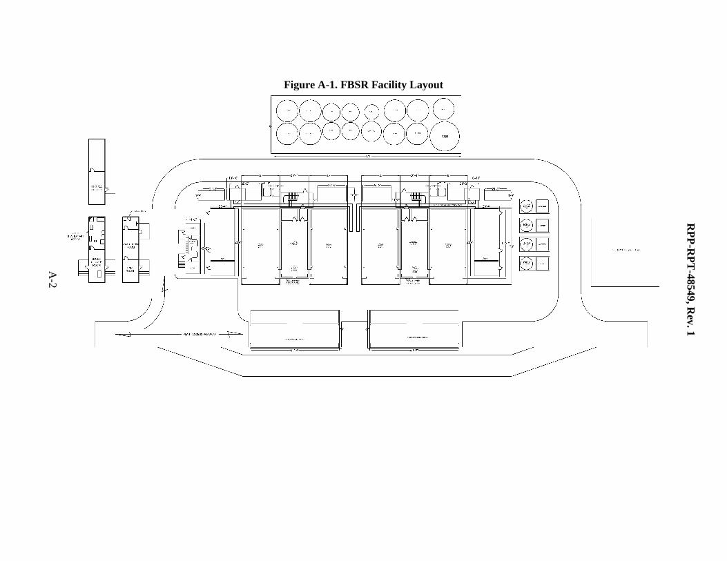
Figure A-1. FBSR Facility Layout
RP
P-R
PT
-48549, R
ev. 1
A-2
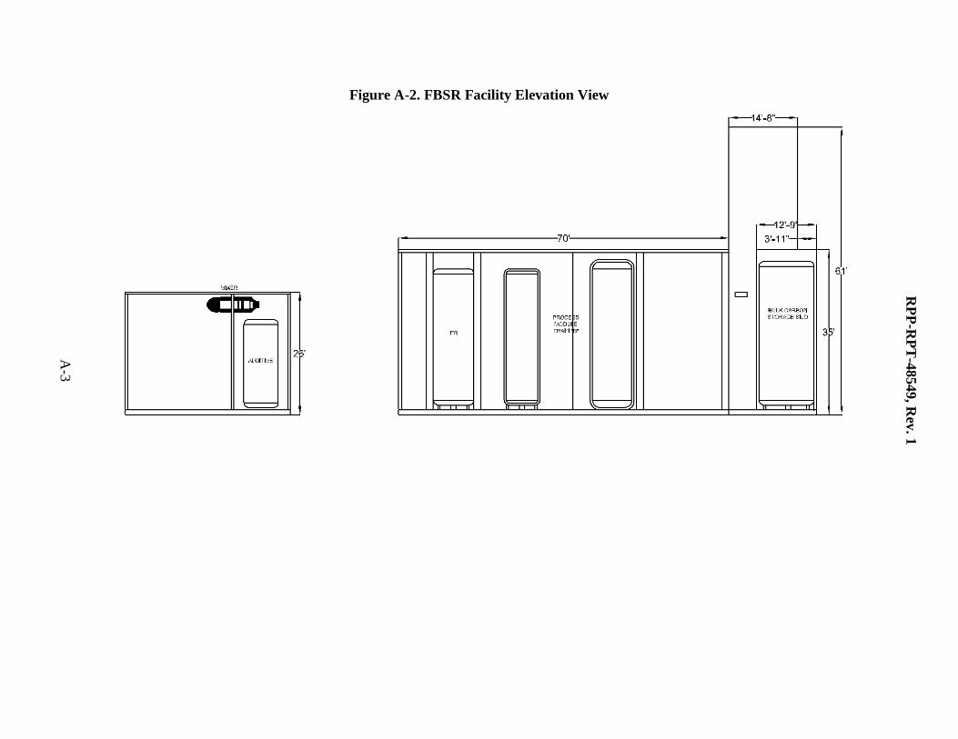
Figure A-2. FBSR Facility Elevation View
RP
P-R
PT
-48549, R
ev. 1
A-3
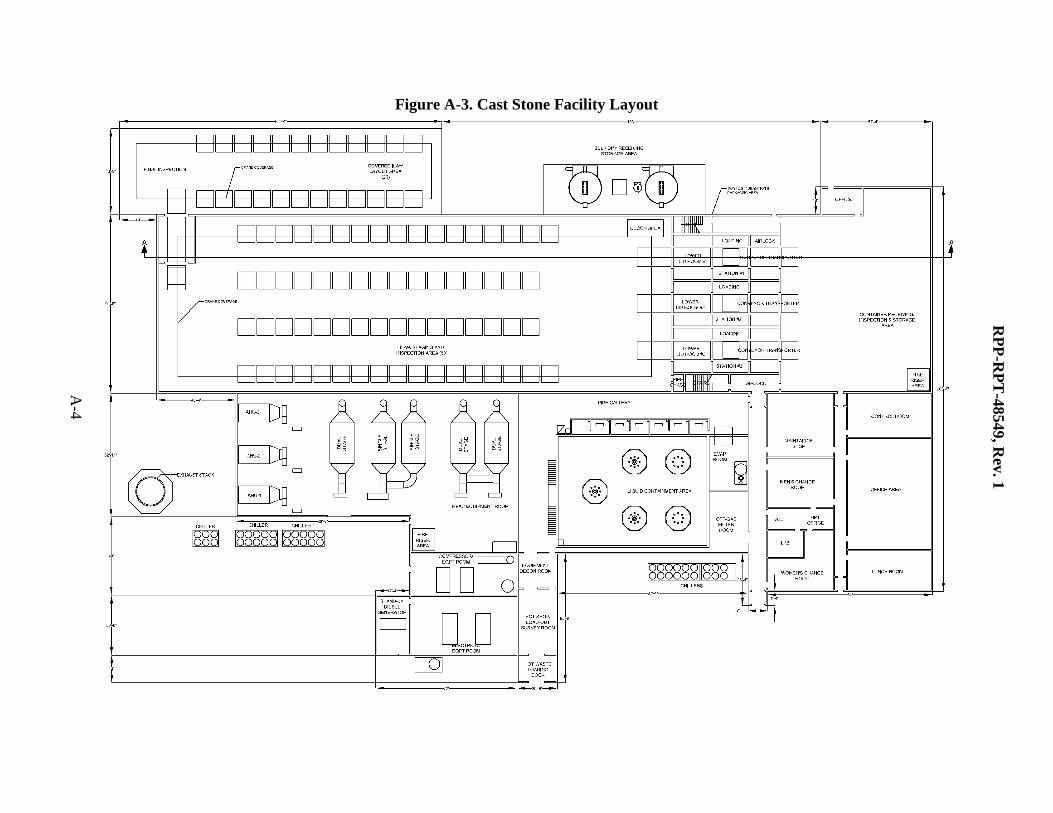
Figure A-3. Cast Stone Facility Layout
RP
P-R
PT
-48549, R
ev. 1
A-4
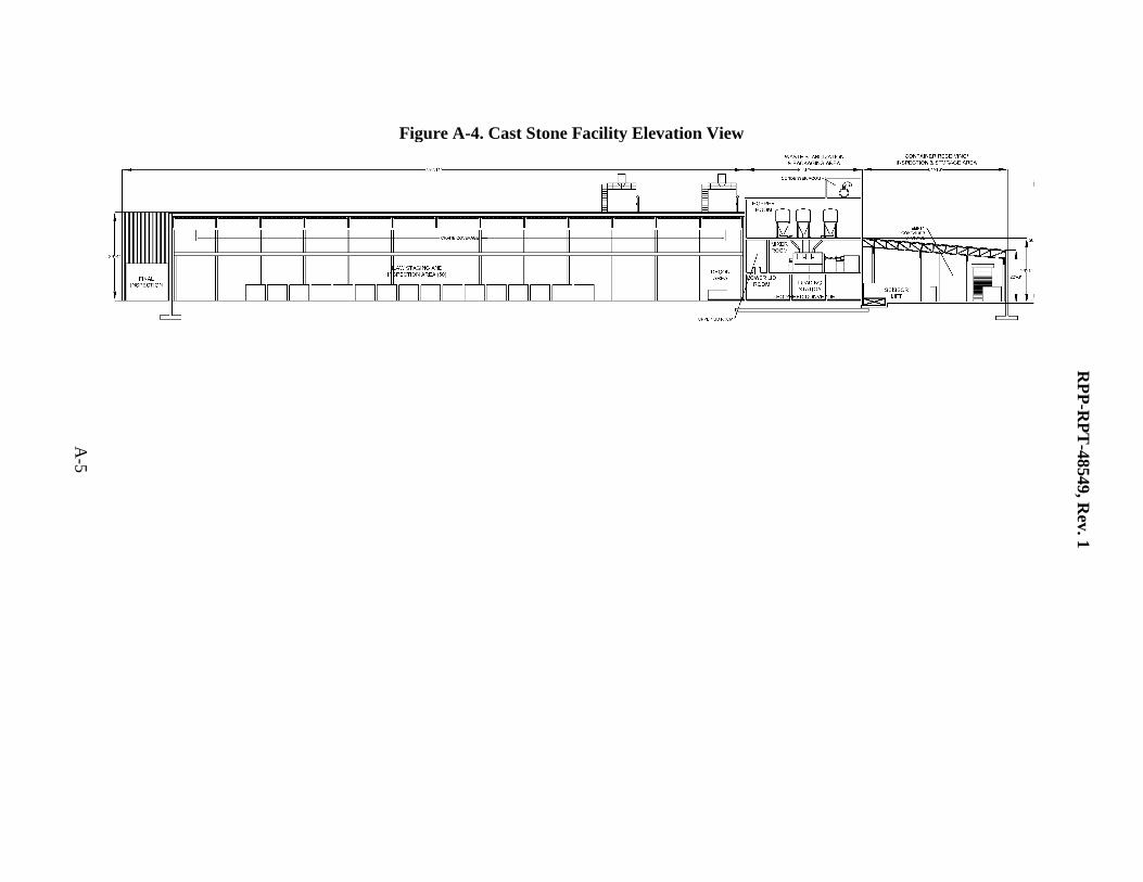
Figure A-4. Cast Stone Facility Elevation View
RP
P-R
PT
-48549, R
ev. 1
A-5
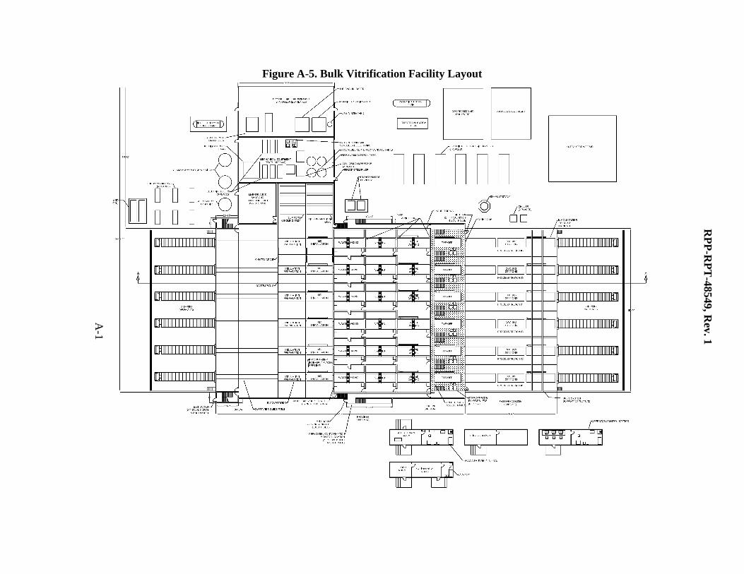
Figure A-5. Bulk Vitrification Facility Layout
A-1
RP
P-R
PT
-48549, R
ev. 1
A-6
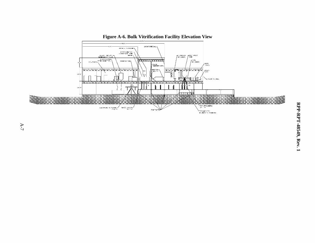
Figure A-6. Bulk Vitrification Facility Elevation View
RP
P-R
PT
-48549, R
ev. 1
A-7
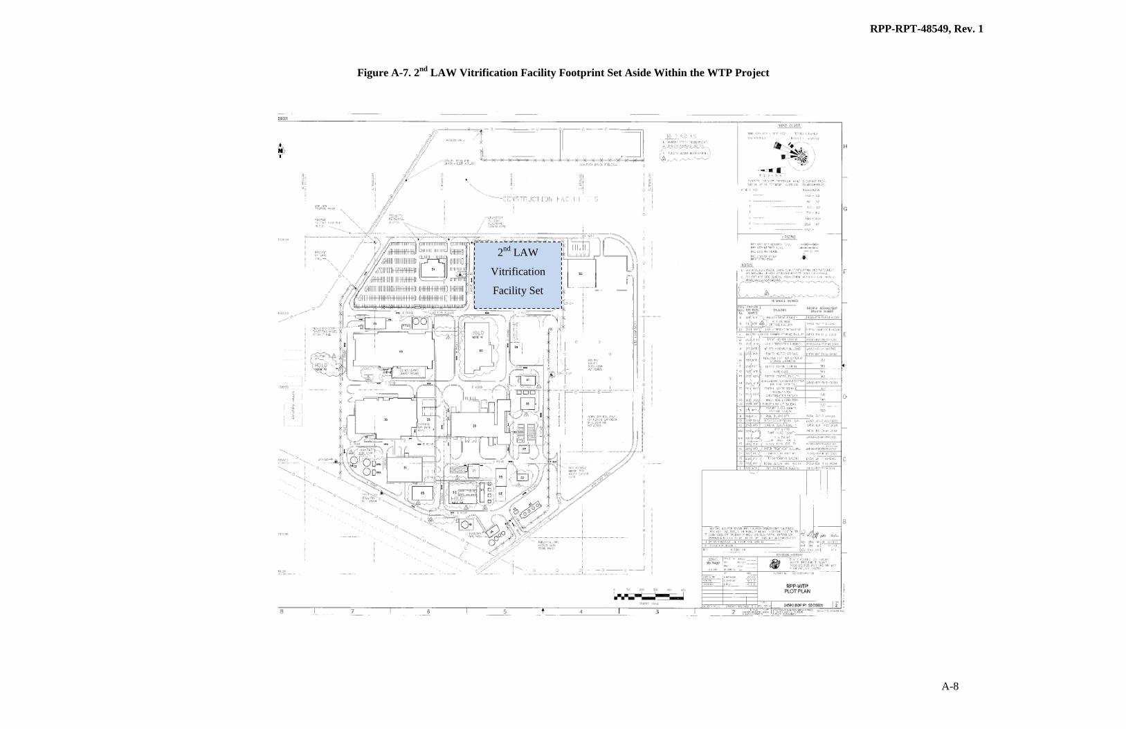
Figure A-7. 2nd
LAW Vitrification Facility Footprint Set Aside Within the WTP Project
RPP-RPT-48549, Rev. 1
A-8
2nd
LAW
Vitrification
Facility Set
Aside
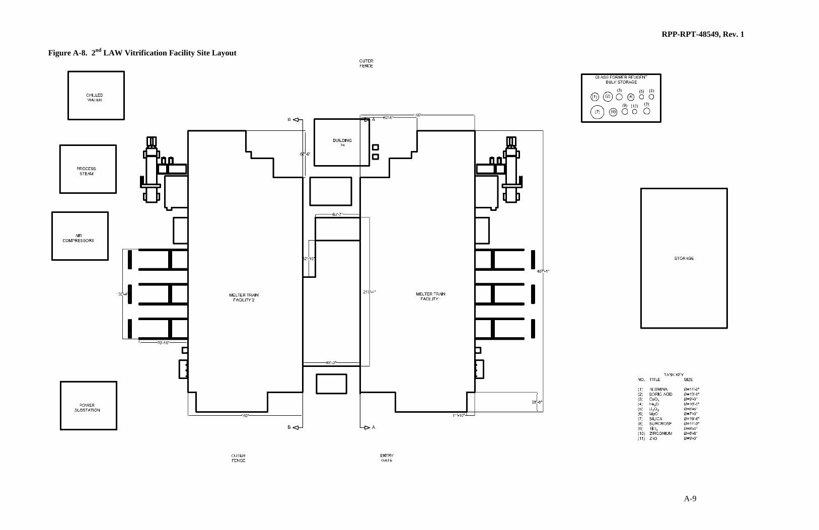
Figure A-8. 2nd
LAW Vitrification Facility Site Layout
RPP-RPT-48549, Rev. 1
A-9
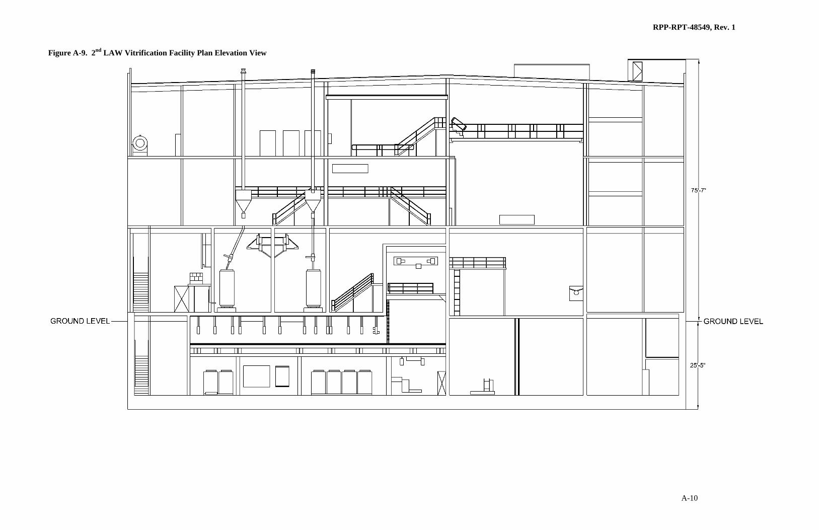
Figure A-9. 2nd
LAW Vitrification Facility Plan Elevation View
A-10
RPP-RPT-48549, Rev. 1

RPP-RPT-48549 Rev. 1
B-1
APPENDIX B – PHOTO LOG OF 200 EAST AREA CANDIDATE SITES WALKDOWN
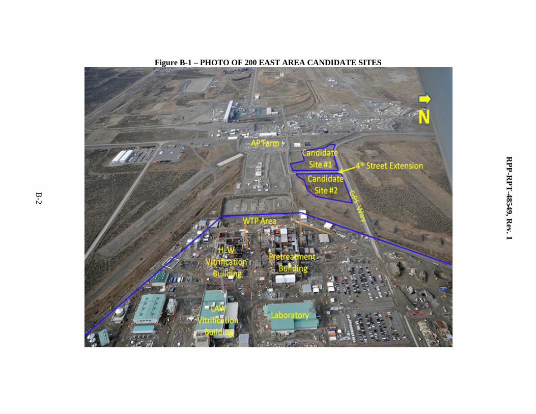
Figure B-1 – PHOTO OF 200 EAST AREA CANDIDATE SITES
RP
P-R
PT
-48549, R
ev. 1
B-2
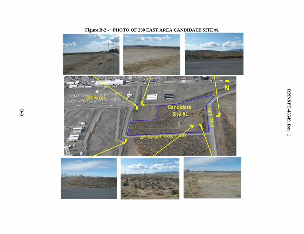
Figure B-2 - PHOTO OF 200 EAST AREA CANDIDATE SITE #1
RP
P-R
PT
-48549, R
ev. 1
B-3
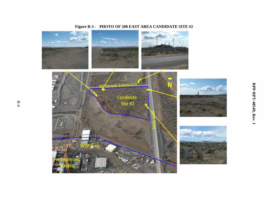
Figure B-3 - PHOTO OF 200 EAST AREA CANDIDATE SITE #2
RP
P-R
PT
-48549, R
ev. 1
B-4
RPP-RPT-48549 Rev. 1
C-1
APPENDIX C – PHOTO LOG OF 200 WEST AREA CANDIDATE SITES WALKDOWN
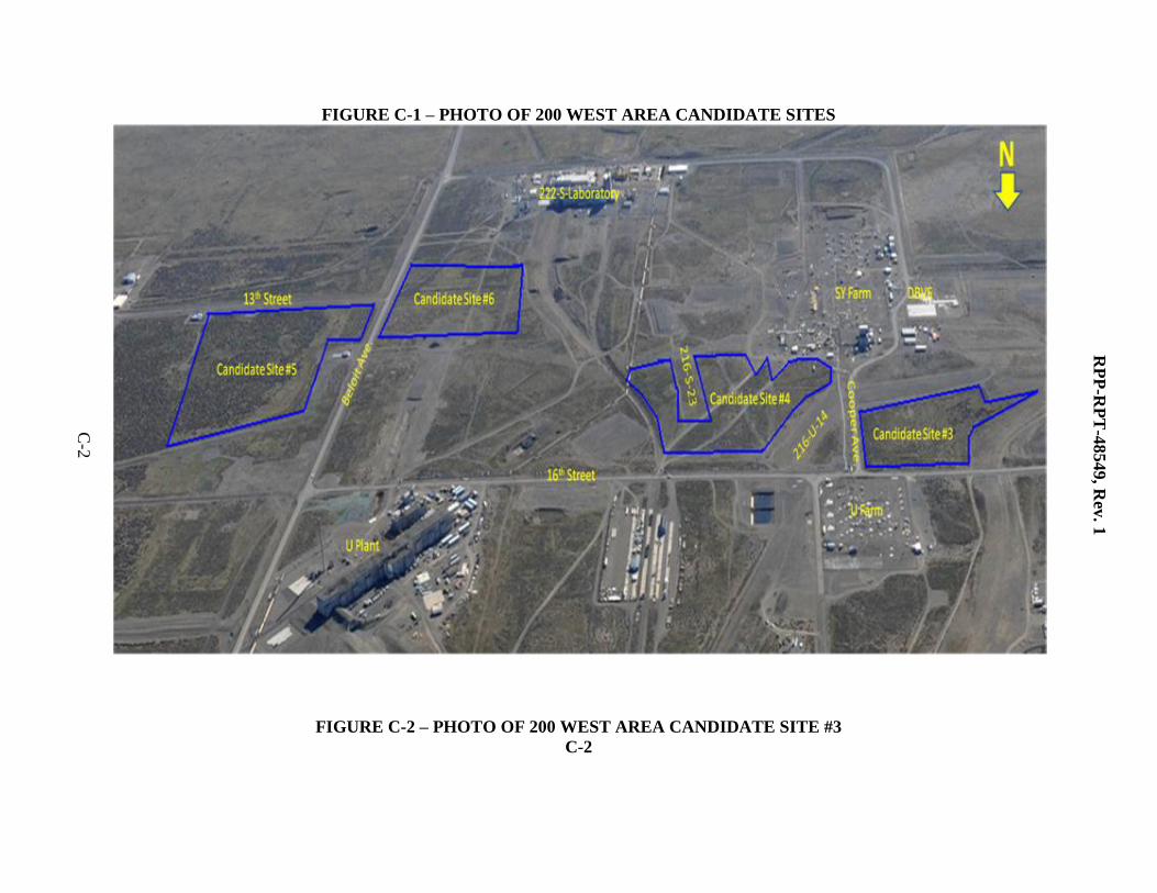
FIGURE C-1 – PHOTO OF 200 WEST AREA CANDIDATE SITES
FIGURE C-2 – PHOTO OF 200 WEST AREA CANDIDATE SITE #3
C-2
RP
P-R
PT
-48549, R
ev. 1
C-2
RP
P-R
PT
-48549, R
ev. 1
C-3
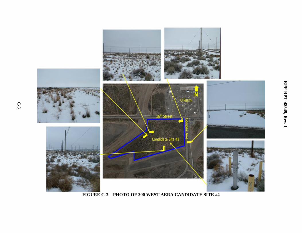
FIGURE C-3 – PHOTO OF 200 WEST AERA CANDIDATE SITE #4
RP
P-R
PT
-48549, R
ev. 1
C-3
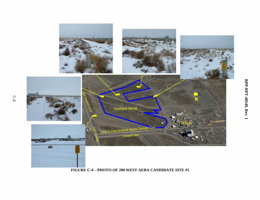
FIGURE C-4 – PHOTO OF 200 WEST AERA CANDIDATE SITE #5
RP
P-R
PT
-48549, R
ev. 1
C-5
C
-4
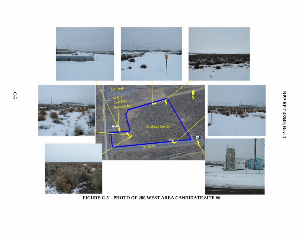
FIGURE C-5 – PHOTO OF 200 WEST AREA CANDIDATE SITE #6
RP
P-R
PT
-48549, R
ev. 1
C-6
C-5
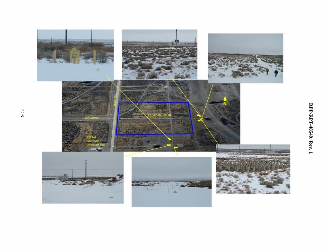
RP
P-R
PT
-48549, R
ev. 1
C-6


