1
! CAUTION
The instructions can not be provided for any other installation other than that of the Vigo brand.
The warranty will be voided if the following was not performed properly.
! WARNING
! SAFETY PRECAUTIONS
IMPORTANT
Maintenance and other important non-personal injury and non-material damage instructions
or statements that should be observed.
It is highly advised to dry fit the unit prior to any installation.
Instructions that, if ignored, could result in death or serious personal injury caused by
incorrect handling or installation of the product. These instructions must be observed for
safe installation.
VIGO INDUSTRIES INSTALLATION GUIDE FOR
SHOWER ENCLOSURE (MODEL VG06042A)
This Installation Guide uses the following symbols to indicate important information.
Always observe the instructions indicated by these symbols.

2
2
6
8
10
1128
4
39 or 121
13
17
2
GLASS THICKNESS 3/8"
NOTE: INSTALLATION MUST BE DONE BY A QUALIFIED, LICENSED PROFESSIONAL.
5
7
15
29
14
23
16
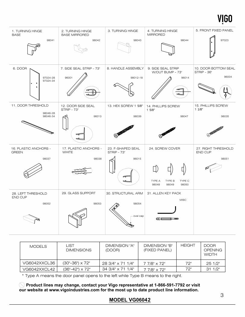
Parts List
1. Turning hinge base (1pc)
2. Turning hinge base mirrored (1pc)
3. Turning hinge (1pc)
4. Turning hinge mirrored (1pc)
5. Front fixed panel (1pc)
6. Door (1pc)
7. Side seal strip (1pc)
8. Handle assembly (1pc)
9. Side seal strip w/out bump (1pc)
10. Door bottom seal strip (1pc+1pc extra)
11. Door threshold (1pc)
12. Door side seal strip (1pc)
13. Hex screw 1 5/8" (2pc)
14. Phillips screw 1 5/8" (2pc)
15. Phillips screw 1 1/8" (2pc)
16. Plastic anchor - green (4pc)
17. Plastic anchor - white (2pc)
18. Not used
19. Not used
20. Not used
21. Not used
22. Not used
23. F-shaped seal strip (1pc)
24. Screw cover (Type A -2pc; Type B-8pc;
Type C- 4pc)
25. Not used
26. Not used
27. Right threshold end cup (1pc)
28. Left threshold end cup (1pc)
29. Glass support (2pc)
30. Structural arm (1pc)
31. Allen key pack (1 pack)
30
15
MODEL VG06042 PIROUETTE
PLEASE READ INSTRUCTIONS BEFORE PROCEEDING
INSTALLATION INSTRUCTIONS FOR SHOWER DOOR
15. PHILLIPS SCREW1 1/8"
29. GLASS SUPPORT
MODEL VG06042
3
30. STRUCTURAL ARM
2. TURNING HINGEBASE MIRRORED
4. TURNING HINGEMIRRORED
5. FRONT FIXED PANEL
6. DOOR 7. SIDE SEAL STRIP - 73" 8. HANDLE ASSEMBLY 9. SIDE SEAL STRIP W/OUT BUMP - 73"
10. DOOR BOTTOM SEALSTRIP - 36"
14. PHILLIPS SCREW1 5/8"
13. HEX SCREW 1 5/8"12. DOOR SIDE SEALSTRIP - 73"
11. DOOR THRESHOLD
16. PLASTIC ANCHORS -GREEN
17. PLASTIC ANCHORS -WHITE
DIMENSION "B"(FIXED PANEL)
DIMENSION "A"(DOOR)
34 3/4" x 71 1/4"7 7/8" x 72"
HEIGHT
72"
LISTDIMENSIONS
96001
24. SCREW COVER
72"(36"-42") x 72"
(30"-36") x 72" 28 3/4" x 71 1/4"
7 7/8" x 72"
MODELS
VG6042XXCL36
96013
98037 98038
27. RIGHT THRESHOLDEND CUP
28. LEFT THRESHOLDEND CUP
1. TURNING HINGEBASE
3. TURNING HINGE
VG6042XXCL42
* Type A means the door panel opens to the left while Type B means to the right.
23. F-SHAPED SEALSTRIP - 73"
TYPE A TYPE B TYPE C
98041 98042 98043 98044 97023
97024-2897024-34
98012-18 96014
98046-2898039 98047 98035
96015
98048 98049 98050
98051
98052 98053 98054
96004
oval cap
ALLEN KEY PACK
MISC
31.
98046-34
Product lines may change, contact your Vigo representative at 1-866-591-7792 or visit
our website at www.vigoindustries.com for the most up to date product line information.
DOOROPENINGWIDTH
25 1/2"31 1/2"
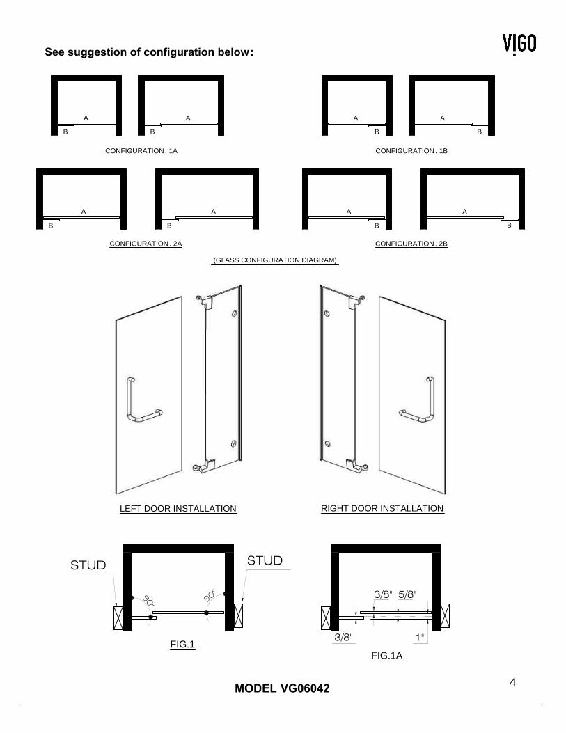
(GLASS CONFIGURATION DIAGRAM)
4MODEL VG06042
See suggestion of configuration below:
CONFIGURATION. 2A
CONFIGURATION. 1A
A
B
A
B
B
A
B
A
CONFIGURATION. 1B
B
A
B
A
CONFIGURATION. 2B
A
B
A
B
RIGHT DOOR INSTALLATIONLEFT DOOR INSTALLATION
FIG.1
90°90°
STUDSTUD
FIG.1A
1"3/8"
3/8" 5/8"
Fiberglass, acrylic or sheetrock construction might not be sufficiently strong enough to support the shower door
enclosure. You should use the wood framing from behind the face edge of the stall to provide a secure mounting
to the door. Apply a bead of silicone between the walls and base of the stall.
For optimum performance, you should install the shower door perfectly level on a level surface. By not leveling
the unit during construction the unit may leak causing possible water damage.
IMPORTANT
Compare items on your invoice with what you have received. Carefully review the Parts List on page 2. If any
items are missing, please call Vigo Industries at 1-866-591-7792. Please check our website at
www.vigoindustries.com for additional information or instructional videos.
BEFORE STARTING
INSTALLATION OF THE SHOWER DOORS BY AN INEXPERIENCED PERSON MAY RESULT IN GLASS
BREAKAGE AND CONSEQUENTLY, CAUSE PERSONAL INJURY OR DEATH.
!
INSTALLATION INSTRUCTION
Installer is responsible for determining attachment method. Anchors are provided as one means of
installation. Recommended installation is into studs behind the wall. This is the strongest means of
installation.
REQUIRED TOOLS:
- Square and/or Phillips #1 and #2 screwdriver
- Flat head screwdriver
- Electric drill; 3/32", 1/8", 3/16" or 7/32" drill bit (According to wall)
- Level
- Measuring tape
- Non permanent pencil
- Clear silicone caulking
- Utility knife; Hacksaw
WE STRONGLY RECOMMEND THAT A LICENSED PROFESSIONAL INSTALL THIS STANDING SHOWER
CABIN AND INCLUDE THE ASSISTANCE OF A SECOND PERSON TO INSTALL THE DOOR UNIT.
WARNING
MODEL VG06042
5
PREPARATION STEPS TO FOLLOW BEFORE INSTALLATION
1. Remove the plastic layer from the base border (if needed). Do NOT remove the plastic layer off the plastic
platform of the base or from the face of the hardware until installation is complete.
2. Properly apply silicone to the wall and base joints.
IMPORTANT
To prevent damage to the finish, you should protect the shower cabin bottom with a cardboard protector
before beginning the installation.
Ensure that there is sufficient structural support behind the shower wall to hold the weight of the shower door.
If there is insufficient support, then reinforce the shower walls with wooden studs prior to shower door
installation. [SEE FIG.1 on page 4]
Prior to any installation, mark lines on the floor and wall for proper dry fit. Using painter's tape is a suggested
method. Although the panels are parallel the fixed panel does not sit in alignment with the door panel. Proper
planning is imperative for proper installation. [SEE FIG.1A on page 4]
IMPORTANT:
THE CLEAR GLASS MODEL HAS A REVERSIBLE DOOR AND CAN BE INSTALLED TO THE RIGHT
(CONFIGURATION "A") OR LEFT SIDE (CONFIGURATION "B"). (SEE CONFIGURATION DIAGRAMS ON
PAGE 4)
- Handle fragile items with care to prevent personal injury or material damage.
- The glass panels are tempered and cannot be cut. Never attempt to do so.
- Always rest glass on a level surface
6MODEL VG06042
INSTALLATION STEPS
A1
A2
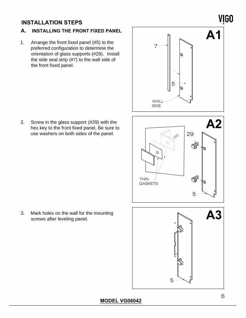
A. INSTALLING THE FRONT FIXED PANEL
1. Arrange the front fixed panel (#5) to the
preferred configuration to determine the
orientation of glass supports (#29). Install
the side seal strip (#7) to the wall side of
the front fixed panel.
2. Screw in the glass support (#29) with the
hex key to the front fixed panel. Be sure to
use washers on both sides of the panel.
3. Mark holes on the wall for the mounting
screws after leveling panel.
7
5
WALLSIDE
THINGASKETS
5
29
A3
5
7MODEL VG06042
!
A4
A5
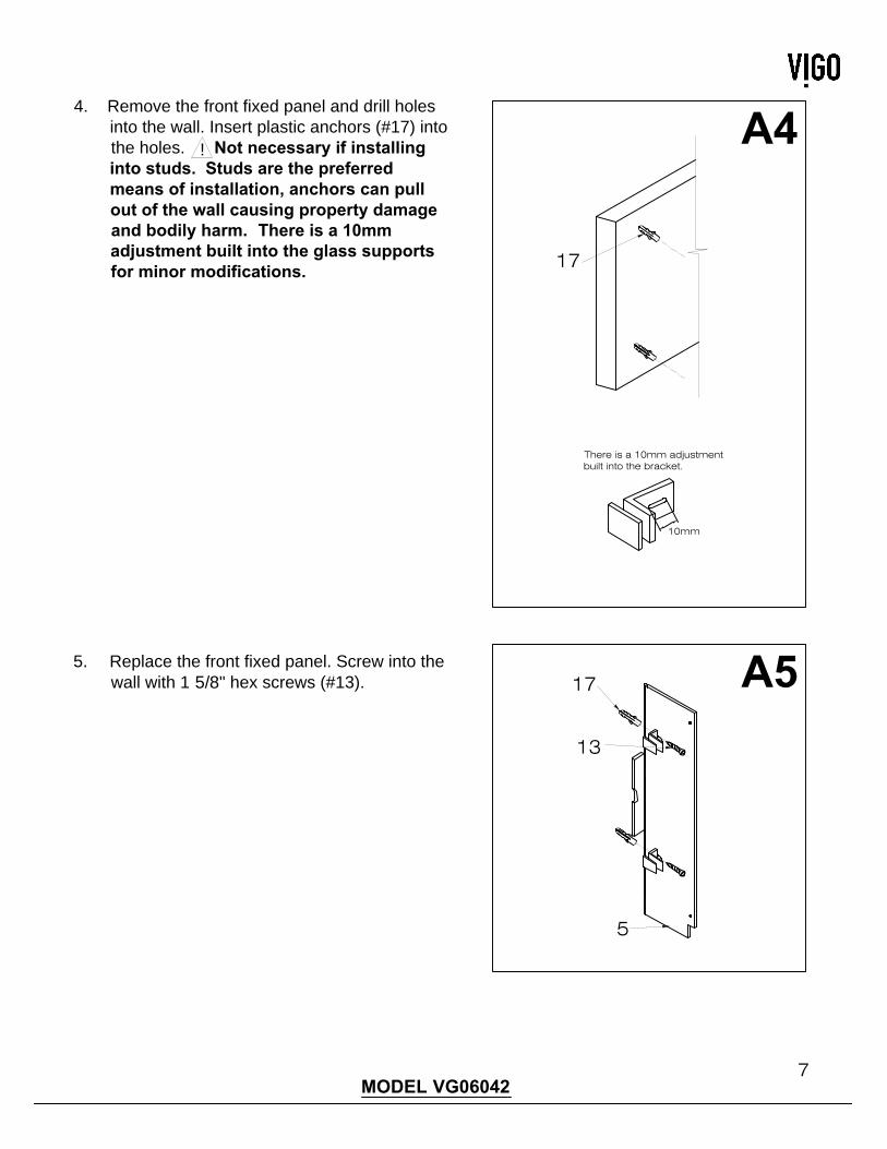
4. Remove the front fixed panel and drill holes
into the wall. Insert plastic anchors (#17) into
the holes. Not necessary if installing
into studs. Studs are the preferred
means of installation, anchors can pull
out of the wall causing property damage
and bodily harm. There is a 10mm
adjustment built into the glass supports
for minor modifications.
5. Replace the front fixed panel. Screw into the
wall with 1 5/8" hex screws (#13).
17
17
13
5
There is a 10mm adjustmentbuilt into the bracket.
10mm
8MODEL VG06042
B1
B2
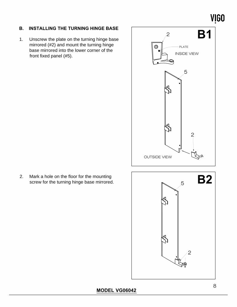
1. Unscrew the plate on the turning hinge base
mirrored (#2) and mount the turning hinge
base mirrored into the lower corner of the
front fixed panel (#5).
2. Mark a hole on the floor for the mounting
screw for the turning hinge base mirrored.
B. INSTALLING THE TURNING HINGE BASE
2
PLATE
5
2
5
2
INSIDE VIEW
OUTSIDE VIEW
9MODEL VG06042
B3
B4
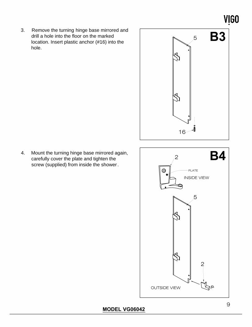
3. Remove the turning hinge base mirrored and
drill a hole into the floor on the marked
location. Insert plastic anchor (#16) into the
hole.
4. Mount the turning hinge base mirrored again,
carefully cover the plate and tighten the
screw (supplied) from inside the shower .
5
16
2
PLATE
5
2
INSIDE VIEW
OUTSIDE VIEW
10MODEL VG06042
B5
B6
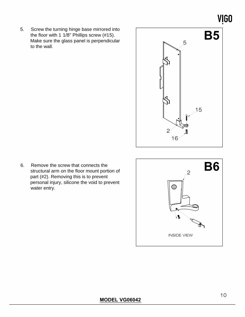
5. Screw the turning hinge base mirrored into
the floor with 1 1/8" Phillips screw (#15).
Make sure the glass panel is perpendicular
to the wall.
6. Remove the screw that connects the
structural arm on the floor mount portion of
part (#2). Removing this is to prevent
personal injury, silicone the void to prevent
water entry.
2
2
15
16
5
INSIDE VIEW
11MODEL VG06042
B7
C1
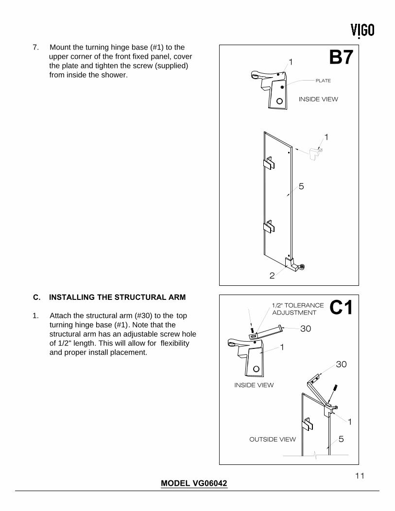
7. Mount the turning hinge base (#1) to the
upper corner of the front fixed panel, cover
the plate and tighten the screw (supplied)
from inside the shower.
1
INSIDE VIEW
2
5
PLATE
1
C. INSTALLING THE STRUCTURAL ARM
1. Attach the structural arm (#30) to the top
turning hinge base (#1).Note that the
structural arm has an adjustable screw hole
of 1/2" length. This will allow for flexibility
and proper install placement.
1/2" TOLERANCEADJUSTMENT
INSIDE VIEW
5
30
1
OUTSIDE VIEW
30
1
12MODEL VG06042
C2
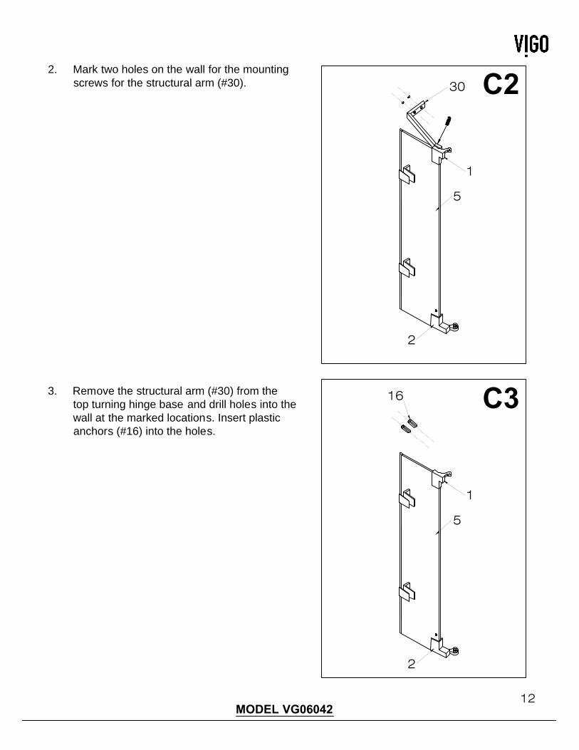
2. Mark two holes on the wall for the mounting
screws for the structural arm (#30).
3. Remove the structural arm (#30) from the
top turning hinge base and drill holes into the
wall at the marked locations. Insert plastic
anchors (#16) into the holes.
5
30
1
2
16C3
5
1
2
13MODEL VG06042MODEL VG06042
C4
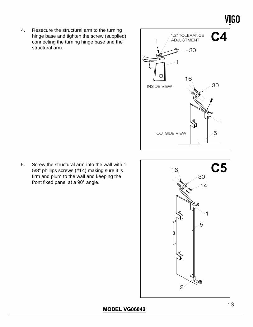
4. Resecure the structural arm to the turning
hinge base and tighten the screw (supplied)
connecting the turning hinge base and the
structural arm.
5. Screw the structural arm into the wall with 1
5/8" phillips screws (#14) making sure it is
firm and plum to the wall and keeping the
front fixed panel at a 90° angle.
1/2" TOLERANCEADJUSTMENT
INSIDE VIEW
5
30
1
OUTSIDE VIEW
30
1
16
C5
5
30
1
2
16
14
14MODEL VG06042MODEL VG06042
D1
D2
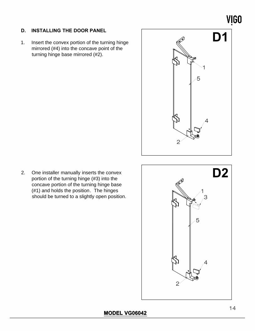
D. INSTALLING THE DOOR PANEL
1. Insert the convex portion of the turning hinge
mirrored (#4) into the concave point of the
turning hinge base mirrored (#2).
2. One installer manually inserts the convex
portion of the turning hinge (#3) into the
concave portion of the turning hinge base
(#1) and holds the position. The hinges
should be turned to a slightly open position.
5
1
2
4
5
1
2
4
3
15MODEL VG06042
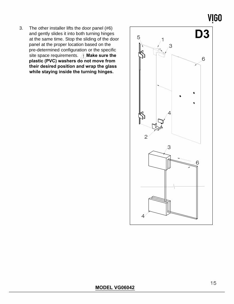
D3
3. The other installer lifts the door panel (#6)
and gently slides it into both turning hinges
at the same time. Stop the sliding of the door
panel at the proper location based on the
pre-determined configuration or the specific
site space requirements. Make sure the
plastic (PVC) washers do not move from
their desired position and wrap the glass
while staying inside the turning hinges.
4
3
6
5
6
13
2
4
!
16MODEL VG06042
4
3
6
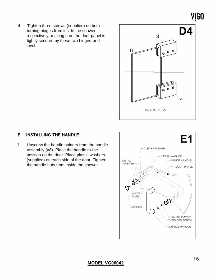
D4
4. Tighten three screws (supplied) on both
turning hinges from inside the shower,
respectively, making sure the door panel is
tightly secured by these two hinges and
level.
INSIDE VIEW
E. INSTALLING THE HANDLE
1. Unscrew the handle holders from the handle
assembly (#8). Place the handle to the
position on the door. Place plastic washers
(supplied) on each side of the door. Tighten
the handle nuts from inside the shower.
E1
DOOR PANEL
OUTSIDE HANDLE
INSIDE HANDLE
SCREW
METALWASHER
WHITETUBE
GLASS SUPPORT
METAL WASHER
THREADED SCREW
CLEAR WASHER
17MODEL VG06042
F. INSTALLING SEAL STRIPS
F1
F2
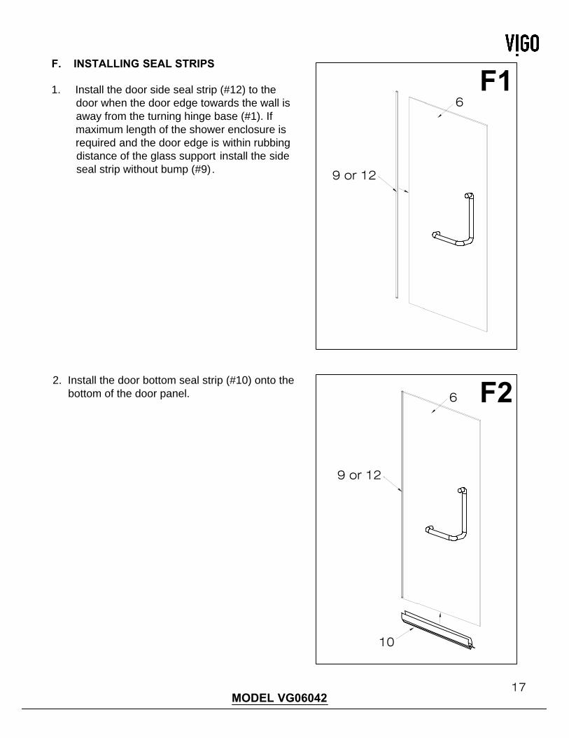
1. Install the door side seal strip (#12) to the
door when the door edge towards the wall is
away from the turning hinge base (#1). If
maximum length of the shower enclosure is
required and the door edge is within rubbing
distance of the glass support install the side
seal strip without bump (#9).
2. Install the door bottom seal strip (#10) onto the
bottom of the door panel. 6
10
9 or 12
6
9 or 12
18MODEL VG06042MODEL VG06042
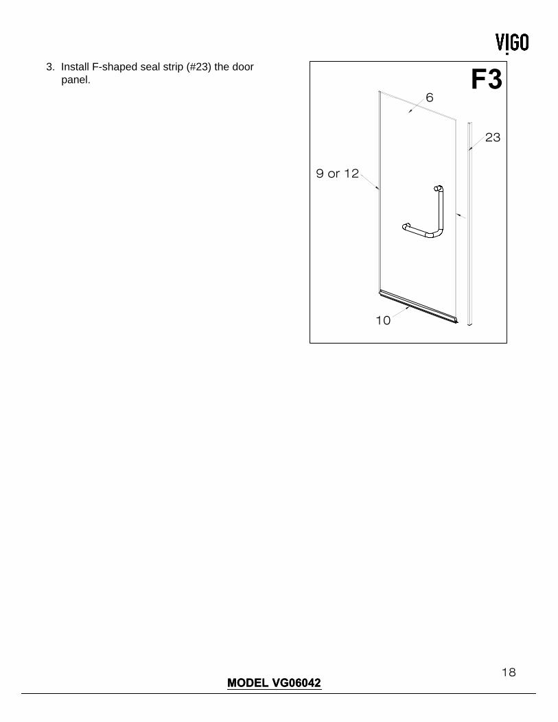
F3
3. Install F-shaped seal strip (#23) the door
panel.
23
6
10
9 or 12
19MODEL VG06042MODEL VG06042
G1
G2
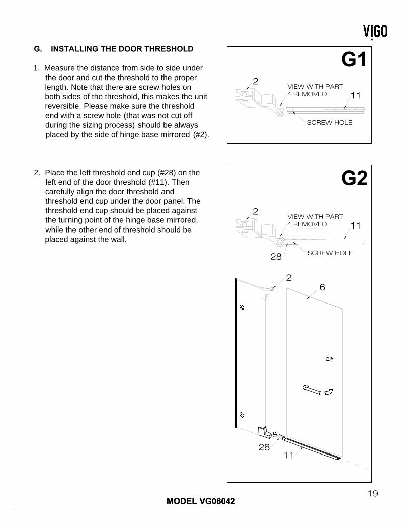
G. INSTALLING THE DOOR THRESHOLD
1. Measure the distance from side to side under
the door and cut the threshold to the proper
length. Note that there are screw holes on
both sides of the threshold, this makes the unit
reversible. Please make sure the threshold
end with a screw hole (that was not cut off
during the sizing process) should be always
placed by the side of hinge base mirrored (#2).
2. Place the left threshold end cup (#28) on the
left end of the door threshold (#11). Then
carefully align the door threshold and
threshold end cup under the door panel. The
threshold end cup should be placed against
the turning point of the hinge base mirrored,
while the other end of threshold should be
placed against the wall.
2VIEW WITH PART4 REMOVED 11
SCREW HOLE
2VIEW WITH PART4 REMOVED 11
28
6
2811
2
SCREW HOLE

20MODEL VG06042
G3
3. Remove the threshold end cup and mark a
hole on the floor for the threshold screw.
4. Remove the door threshold and drill hole into
the floor. Insert plastic anchor (#16) into the
hole.
5. Replace the door threshold and screw into the
floor with 1 1/8" phillips screws (#15).
6. Replace the threshold end cup (#28).
2VIEW WITH PART4 REMOVED 11
Mark hole onthe floor here
G4
2 16
5
G5
216
11
15
5
G6
2 11
5
28
21MODEL VG06042
H1
I1
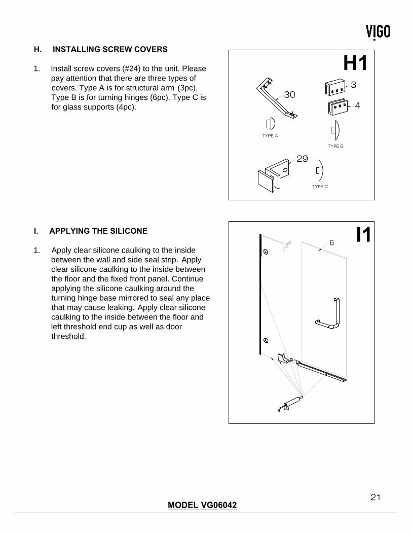
H. INSTALLING SCREW COVERS
1. Install screw covers (#24) to the unit. Please
pay attention that there are three types of
covers. Type A is for structural arm (3pc).
Type B is for turning hinges (6pc). Type C is
for glass supports (4pc).
I. APPLYING THE SILICONE
1. Apply clear silicone caulking to the inside
between the wall and side seal strip. Apply
clear silicone caulking to the inside between
the floor and the fixed front panel. Continue
applying the silicone caulking around the
turning hinge base mirrored to seal any place
that may cause leaking. Apply clear silicone
caulking to the inside between the floor and
left threshold end cup as well as door
threshold.
6
TYPE A
TYPE B
TYPE C
4
330
29
IMPORTANT!
- WAIT 24 HOURS BEFORE USING SHOWER
- DO NOT ALLOW WATER TO DIRECTLY HIT DOOR SEAL STRIPS.
CLEANING INSTRUCTIONS FOR THE SHOWER CABIN AND DOOR PANEL
1. Use a mild liquid household cleaner to keep metal surfaces bright and clean. Rinse well and
dry with a soft, clean cloth.
2. Remove dust with a soft, damp cloth.
3. Use a standard household window cleaner to clean the glass panels.
4. A water beading treatment, similar to what you would use on an automobile windshield, can be
used on the inside of the glass to keep it looking brand new.
5. Use rubbing alcohol to clean and remove grease, oil, paint and ink.
6. Should you accidentally scratch or stain your shower enclosure, use a liquid automobile polish
to remove.
IMPORTANT!
1. DO NOT use abrasive cleaners, scrapers, metal brushes or any items that could scratch or dull
the surface.
2. DO NOT allow surface to come in contact with acetone (nail polish remover), dry cleaning
solution, lacquer thinner, gasoline or other similar products.
REGULAR CARE AND MAINTENANCE OF YOUR VIGO SHOWER ENCLOSURE
Your home is a moving entity, shifting and settling over time. Vigo understands this and has
designed their shower enclosures with this in mind. It is the responsibility of the homeowner or end
user to maintain the integrity of their newly installed enclosure, using the integrated adjustability
features. In order to keep your shower enclosure in optimal working condition, Vigo recommends
regularly inspecting your enclosure and tightening any hardware that may have loosened during
use. This simple step will insure optimal results from your Vigo shower enclosure for many years to
come.
22MODEL VG06042
23MODEL VG06042MODEL VG06042
VIGO INDUSTRIES, LLC (“VIGO”)
SHOWER ENCLOSURE LIMITED LIFETIME WARRANTY
EFFECTIVE JANUARY 1, 2010
VIGO offers the following limited warranty on each of its Shower Enclosure products* (the “Product”) and the components thereof. This warranty extends only to the original
owner or end-user for personal household use. For commercial uses, additional limitations apply.
VIGO warrants the structural glass component of the Product to be free from defects in workmanship and materials under normal use and service for the period commencing
from the initial date of purchase by the owner or end-user, contractor, or builder, from VIGO or an authorized VIGO dealer, through the lifetime of the original owner or
end-user.
VIGO warrants the hardware components of the Product to be free from defects in workmanship and materials under normal use and service for a period of two (2) years from
the initial date of purchase by the owner or end-user, contractor, or builder, from VIGO or an authorized VIGO dealer.
VIGO warrants the seal strip components of the Product to be free from defects in workmanship and materials under normal use and service for a period of one (1) year from
the initial date of purchase by the owner or end-user, contractor, or builder, from VIGO or an authorized VIGO dealer.
Subject to the Warranty Service provision below, any product reported to the authorized dealer or to VIGO as being defective within the warranty period will be repaired or
replaced (with a product of equal value) at the option of VIGO. This warranty extends to the original owner or end-user and is not transferable to a subsequent owner.
Neither the distributor, authorized VIGO dealer, nor any other person has been authorized to make any affirmation, representation, or warranty other than those contained in
this warranty. Any affirmation, representation, or warranty other than those contained in this warranty shall not be enforceable against VIGO or any other person.
VIGO reserves the right to modify this warranty at any time, it being understood that such modifications will not alter the warranty conditions applicable at the time of sale of the
products in question.
Limitations
This warranty shall not apply to instances of incorrect operating procedures, breakages, or damages caused by fault through improper installation, carelessness, abuse,
misuse, misapplication, improper maintenance, or alteration of the Product, as well as chemical or natural corrosion, accident, fire, flood, an act of God, or any other casualty.
Avoid abrasive cleaners, steel wools, and harsh chemicals as these will scratch, damage, and / or dull the product and / or finish and void this warranty. The owner/end-user
of the Product covered by the present warranty is entirely responsible for its proper installation and any applicable plumbing or electrical wiring. VIGO neither installs nor
supervises the installation nor hires a contractor for this purpose; consequently, VIGO cannot be held responsible for any default, breakage, or damages caused thereby or
resulting thereof, either directly or indirectly.
The owner/end-user must provide access to the components of the Product as described in the installation guide so that VIGO can execute the warranty specified herein. If
such access is not available, all expenses to provide said access will be the responsibility of the owner/end-user.
This warranty does not apply to Products that have not been installed or operated in accordance with instructions supplied by VIGO and all applicable rules, regulations, and
legislation pertaining to such installations.
This warranty does not apply unless the VIGO Product is installed by fully insured licensed professionals. Vigo strongly recommends that such licensed professionals have
experience in the installation of bathroom and kitchen products. Installation of certain products, including, without limitation, glass products (i.e., shower doors and glass sinks)
by an inexperienced person may result in glass breakage and, consequently, cause personal injury or death.
VIGO is not liable for personal injuries or deaths to any persons or for any direct, special, incidental, or consequential damage, loss of time, loss of profits, inconvenience,
incidental expenses, labor or material charges, or any other costs resulting from the use of the product or equipment or pertaining to the application of the present warranty, or
resulting from the removal or replacement of any product or element or part covered by this warranty.
EXCEPT AS OTHERWISE PROVIDED ABOVE, VIGO MAKES NO WARRANTIES, EXPRESSED OR IMPLIED, INCLUDING WARRANTIES OF MERCHANTABILITY AND
FITNESS FOR A PARTICULAR PURPOSE OR COMPLIANCE WITH ANY CODE.
In any case, VIGO cannot be held liable for any amount over and above the purchase price paid for the Product by the owner/end-user, contractor, or builder.
Commercial Limitations
In addition to the above conditions and limitations, the warranty period for products installed for commercial applications or used in commercial ventures is one (1) year from
the initial date of purchase by the owner/end-user, contractor, or builder from an authorized dealer. VIGO is not responsible for loss of use or profit under any circumstances. If
the product is used as a display, the warranty period begins when the product is placed on display. This warranty gives the owner/end-user specific legal rights. The
owner/end-user may also have other rights which can vary from one state or province to another.
Warranty Service
In order to obtain service provided under this warranty during regular business hours, contact the dealer or distributor who sold the unit, or contact VIGO directly. VIGO will
provide the warranty service described above when the following conditions have been met: the failure is of the nature or type covered by the warranty; the user has informed
an authorized VIGO Agent or VIGO’s warranty service department representative of the nature of the problem during the warranty period; conclusive evidence (e.g., proof of
purchase or installation) is provided to the foregoing by the user proving that the failure occurred or was discovered within the warranty period; an authorized independent
service person or company representative has been permitted to inspect the product during regular business hours within a reasonable time after the problem was reported by
the user. VIGOs warranty obligation shall be discharged upon tender of replacement or repair. The customer’s refusal to accept the tender terminates VIGO’s warranty
obligations.
*Certain models are pending approval.
Certification may be ended by VIGO or certification agencies without notice.


