COMPUTER AIDED DYNAMICS OF MACHINERY
Stoyanov S. PhD Faculty of Mechanical and Manufacturing Engineering – University of Ruse, Ruse, Bulgaria
Abstract: Methods and tools for computer aided dynamics are analysed and synthesized. Software systems are developed and implemented in the higher education process. Theories are visualised through simulations and animations. Advanced software systems like MATLAB, Maple, MSC.ADAMS, and LabView are used.
Keywords: DYNAMICS OF MACHINERY, VIBRATIONS, COMPUTER AIDED DESIGN, HIGHER EDUCATION
1. Introduction To be competitive and successful, engineers must have
knowledge and ability to work with advanced software systems. In the area of machinery dynamics these systems are: MATLAB (and its subunits like SimMechanics and Simscape), Maple, SimulationX, MSC.ADAMS, LabView etc. This is the reason to create a modern course on machinery dynamics. It is based both on good theoretical knowledge and on the contemporary software systems. This gives the possibility of including elements of research in the formulated problems [3].
In the area of machinery dynamics two main directions can be differentiated:
Studying the movement of the machine;
Studying the vibration of the machine.
The first task is to study the movement of elements of the machinery, especially the working bodies of a machine. Dynamics of machines with rigid links deals with elements of the machine, which can be regarded as perfectly rigid bodies. Such a determination is idealization, which often is not permitted to make. In this case, the flexible property of the units of the machine is taken into an account. This subject area is dynamics of machines with flexible bodies.
The second task examines the oscillation of the units of the machine, the supports and foundation. Oscillation may be useful or harmful factor depending on the type of the machine and the technological process.
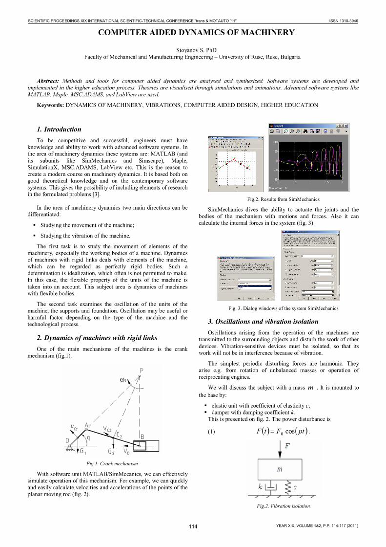
2. Dynamics of machines with rigid links One of the main mechanisms of the machines is the crank
mechanism (fig.1).
Fig.1. Crank mechanism
With software unit MATLAB/SimMecanics, we can effectively simulate operation of this mechanism. For example, we can quickly and easily calculate velocities and accelerations of the points of the planar moving rod (fig. 2).
Fig.2. Results from SimMechanics
SimMechanics dives the ability to actuate the joints and the bodies of the mechanism with motions and forces. Also it can calculate the internal forces in the system (fig. 3)
Fig. 3. Dialog windows of the system SimMechanics
3. Oscillations and vibration isolation Oscillations arising from the operation of the machines are
transmitted to the surrounding objects and disturb the work of other devices. Vibration-sensitive devices must be isolated, so that its work will not be in interference because of vibration.
The simplest periodic disturbing forces are harmonic. They arise e.g. from rotation of unbalanced masses or operation of reciprocating engines.
We will discuss the subject with a mass m . It is mounted to the base by:
elastic unit with coefficient of elasticity c; damper with damping coefficient k.
This is presented on fig. 2. The power disturbance is
(1) ptFtF cos0 .
Fig.2. Vibration isolation
114
SCIENTIFIC PROCEEDINGS XIX INTERNATIONAL SCIENTIFIC-TECHNICAL CONFERENCE "trans & MOTAUTO ’11" ISSN 1310-3946
YEAR XIX, VOLUME 1&2, P.P. 114-117 (2011)

It is known, that the mass movement is described by
(2) ptAx cos .
Moreover, amplitude and phase are respectively:
(3)
4
222
2
2
0
41
pnpc
FA
,
(4) 222
pnparctg
.
The equation (3) is presented graphically on the fig. 3. The amplitude has a minimum when the coefficient of elasticity has its minimum value, while damping coefficient has its maximum value.
Fig.3. Amplitude of forced oscillations (calculated and plotted through
Matlab)
A simple study of phase-frequency characteristics is presented in fig. 4. For example, when c = 1000 N/m and k =1 Ns/m, vibration protection is not effective (curve 1 on fig. 4 and fig. 5a). For c = 1000 N/m and k = 100 Ns/m, the amplitude of the oscillation of the protected mass is significantly smaller (curve 2 on fig. 4 and fig. 5b).
Fig.4. Phase-frequency characteristics for different values of the
damping k, Ns/m: from bottom to top: k=20, k=10, k=5, k=3, k=2, k=1.5, k=1.3, k=1.1, k=1.
0 1 2 3 4 5 6 7 8 9 10-1.5
-1
-0.5
0
0.5
1
1.5
t, s
Am
plitu
da, m
a
0 1 2 3 4 5 6 7 8 9 10-1.5
-1
-0.5
0
0.5
1
1.5
t, s
Am
plitu
da, m
b
Fig.5. Disturbance (green line) and vibrations of the isolated mass (red line)
A software system specifically designed for teaching is shown in fig. 6. It works in an integrated environment of MATLAB.
Fig. 6. Graphical user interface for investigating of vibration protection systems
The developed software system allows simulating the forced vibrations in order to observe the influence of elasticity coefficient, damping ratio and frequency of disturbance upon the velocity, amplitude and amplitude-frequency characteristic.
4. Dynamics of the suspension of vehicles and metal cutting machines
4.1. Dynamical modeling
An approach to modeling of the vehicles is presented on Fig. 7. The aim of this kind of modeling is to investigate the small oscillations under the influence of kinematic disturbances. The basic model consists of two masses - Fig. 7a.
115
SCIENTIFIC PROCEEDINGS XIX INTERNATIONAL SCIENTIFIC-TECHNICAL CONFERENCE "trans & MOTAUTO ’11" ISSN 1310-3946
YEAR XIX, VOLUME 1&2, P.P. 114-117 (2011)
a b
Fig. 7. Modeling of vehicles: a - model with two degrees of freedom (quarter-car model), b - model with four degrees of freedom (half-car
model)
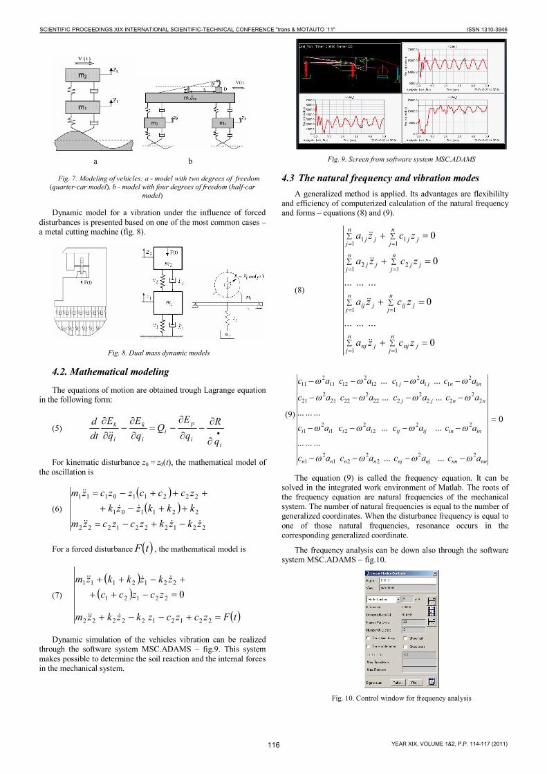
Dynamic model for a vibration under the influence of forced disturbances is presented based on one of the most common cases – a metal cutting machine (fig. 8).
Fig. 8. Dual mass dynamic models
4.2. Mathematical modeling
The equations of motion are obtained trough Lagrange equation in the following form:
(5)
ii
pi
i
k
i
k
q
RqE
QqE
qE
dtd
For kinematic disturbance z0 = z0(t), the mathematical model of the oscillation is
(6)
2212221222
221101
222110111
zkzkzczczmkkkzzkzccczzczm
For a forced disturbance tF , the mathematical model is
(7)
tFzczczkzkzm
zczcczkzkkzm
2212122222
22121
2212111
0
Dynamic simulation of the vehicles vibration can be realized through the software system MSC.ADAMS – fig.9. This system makes possible to determine the soil reaction and the internal forces in the mechanical system.
Fig. 9. Screen from software system MSC.ADAMS
4.3 The natural frequency and vibration modes A generalized method is applied. Its advantages are flexibililty
and efficiency of computerized calculation of the natural frequency and forms – equations (8) and (9).
(8)
n
jjnj
n
jjnj
n
jjij
n
jjij
n
jjj
n
jjj
n
jjj
n
jjj
zcza
zcza
zcza
zcza
11
11
12
12
11
11
0
.........
0
.........
0
0
(9) 0
......
.........
......
.........
......
......
222
221
21
222
221
21
22
222
2222
22212
21
12
112
1122
12112
11
nnnnnjnjnnnn
ininijijiiii
nnjj
nnjj
acacacac
acacacac
acacacac
acacacac
The equation (9) is called the frequency equation. It can be solved in the integrated work environment of Matlab. The roots of the frequency equation are natural frequencies of the mechanical system. The number of natural frequencies is equal to the number of generalized coordinates. When the disturbance frequency is equal to one of those natural frequencies, resonance occurs in the corresponding generalized coordinate.
The frequency analysis can be down also through the software system MSC.ADAMS – fig.10.
Fig. 10. Control window for frequency analysis
116
SCIENTIFIC PROCEEDINGS XIX INTERNATIONAL SCIENTIFIC-TECHNICAL CONFERENCE "trans & MOTAUTO ’11" ISSN 1310-3946
YEAR XIX, VOLUME 1&2, P.P. 114-117 (2011)

5. Active control of vehicle suspension system The purpose of the suspension of vehicles is:
to create ride comfort, i.e. protection of the passenger, driver, and cargo from vibrations due to roughness of road surface;
to reduce the dynamical loads and to provide sufficient reliability and stability.
The first task is known as "Skyhook control". The second task is known as "Groudhook control". Better comfort requires a soft suspension, while the sustainability of the control has conflicting requirements. The best way is to seek an optimal solution. This approach is called "Hybrid control".
A magnetorheological damper is a damper filled with magnetorheological fluid, which is controlled by a magnetic field, usually using an electromagnet. This allows the damping characteristics to be continuously controlled by varying the power of the electromagnet.
Fig. 11 shows the increase in resistance coefficient k of the damper by increasing the voltage supplied to the electromagnets. The increase continues until the current saturation. Typical is the presence of hysteresis at low speed.
Fig.11. Ccharacteristic of a magnetorheological damper
6. Mechatronic systems Each machine unit consists of an engine, transmission, actuator
and management system. When the management system contains electronic and software components, the machine is a mechatronic system. In this sense, most modern machines are mechatronic systems.
In this course educational robot MINDSTORMS NXT 2.0 is implemented (Fig. 12) It helps students to understand technology and engineering concepts with hands-on, naturally motivating building sets, programming software, and curriculum relevant activity materials. Students explore problems and invent their own solutions. They behave as young scientists and technical investigators.
MINDSTORMS NXT 2.0 combines the versatility of the LEGO building system with new technologies, an intelligent microcomputer brick and intuitive drag-and-drop programming software.
Fig. 12. LEGO MINDSTORMS NXT 2.0 features
The NXT “intelligent Brick” includes:
32-bit ARM7 microprocessor;
Support for Bluetooth wireless communication;
1 USB 2.0 port;
4 input ports;
3 output ports.
The main sensors of this mechatronic system are:
The Touch Sensor;
The Light Sensor;
Sound Sensor;
Ultrasonic Sensor;
Compass Sensor;
Accelerometer Sensor.
7. Conclusion Software systems in the area of the machinery dynamics are
created and implemented. The quality of educational process is improved. Computer simulations and animations visualize theories and accelerate learning. The software series also provide tools for engineers to perform dynamic analysis and calculation for design parameter estimations.
The study was supported by contract № BG051PO001-3.3.04/28, "Support for the Scientific Staff Development in the Field of Engineering Research and Innovation”. The project is funded with support from the Operational Programme "Human Resources Development" 2007-2013, financed by the European Social Fund of the European Union.
REFERENCES
[1] Jordanov J.T. MATLAB in Dynamics. Matlab Central File Exchange, MathWorks, 2004
[2] Stejskal, V., et all. Mechanics with MATLAB. Leonardo da Vinci project ‘MechMat”, 2001
[3] Vitliemov, V. Making new Problems in Mechanics from old ones. 2. ed. University of Rousse, Rousse, 2004 (in Bulgarian)
CORRESPONDENCE
Svetlin Stoyanov, PhD University of Ruse Faculty of Mechanical and Manufacturing Engineering Department of Technical Mechanics Studentska Str 8 7017 Ruse, Bulgaria
117
SCIENTIFIC PROCEEDINGS XIX INTERNATIONAL SCIENTIFIC-TECHNICAL CONFERENCE "trans & MOTAUTO ’11" ISSN 1310-3946
YEAR XIX, VOLUME 1&2, P.P. 114-117 (2011)


