
6A
SPORT JET INSTALLATION
90-858804 AUGUST 1998 Page 6A-1
SECTION 6A – SPORT JET INSTALLATION
Table of Contents
General Information 2. . . . . . . . . . . . . . . . . . . . . . . . . . Notice to Installer 2. . . . . . . . . . . . . . . . . . . . . . . . . . Torque Specifications 3. . . . . . . . . . . . . . . . . . . . . . Serial Number Decal Location 3. . . . . . . . . . . . . . . Corrosion Protection 4. . . . . . . . . . . . . . . . . . . . . . .
Installation Requirements 4. . . . . . . . . . . . . . . . . . . . . Battery/Battery Cables 4. . . . . . . . . . . . . . . . . . . . . Boat Construction 4. . . . . . . . . . . . . . . . . . . . . . . . . Engine Compartment Ventilation 5. . . . . . . . . . . . Exhaust System 5. . . . . . . . . . . . . . . . . . . . . . . . . . . Fuel Delivery System 6. . . . . . . . . . . . . . . . . . . . . . Instrumentation 7. . . . . . . . . . . . . . . . . . . . . . . . . . . Wiring Diagrams 8. . . . . . . . . . . . . . . . . . . . . . . . . . Impeller Selection 9. . . . . . . . . . . . . . . . . . . . . . . . . Remote Control and Cables 9. . . . . . . . . . . . . . . . Steering Helm and Cable 10. . . . . . . . . . . . . . . . . . Sport Jet Hull Dimensions 10. . . . . . . . . . . . . . . . .
Installing Jet Pump 12. . . . . . . . . . . . . . . . . . . . . . . . . . Hull Cutout 12. . . . . . . . . . . . . . . . . . . . . . . . . . . . . . Steering Cable Adjustment 14. . . . . . . . . . . . . . . . Shift Cable Adjustment 15. . . . . . . . . . . . . . . . . . . .
Bilge Siphon Feature 18. . . . . . . . . . . . . . . . . . . . . . . . Installing Bilge Siphon 18. . . . . . . . . . . . . . . . . . . .
Water By-Pass System 18. . . . . . . . . . . . . . . . . . . . . . . Installing Powerhead 20. . . . . . . . . . . . . . . . . . . . . . . .
Throttle Cable Adjustment 21. . . . . . . . . . . . . . . . . Battery Connection 22. . . . . . . . . . . . . . . . . . . . . . . Oil Injection System 22. . . . . . . . . . . . . . . . . . . . . . Check Oil Pump Adjustment 23. . . . . . . . . . . . . . .
Trim Plate Adjustment 23. . . . . . . . . . . . . . . . . . . . . . . Pre-delivery Inspection 24. . . . . . . . . . . . . . . . . . . . . . .
Check Before Running 24. . . . . . . . . . . . . . . . . . . . On the Water Test 24. . . . . . . . . . . . . . . . . . . . . . . . Post Water Test 24. . . . . . . . . . . . . . . . . . . . . . . . . .

SPORT JET INSTALLATION
Page 6A-2 90-858804 AUGUST 1998
General Information
Notice to InstallerThroughout this publication, “Warnings” and “Cautions” (accompanied by the InternationalHazard Symbol ! ) are used to alert the installer to special instructions concerning a particu-lar service or operation that may be hazardous if performed incorrectly or carelessly. –– Ob-serve Them Carefully!
These “Safety Alerts,” alone, cannot eliminate the hazards that they signal. Strict com-pliance to these special instructions when performing the service, plus “common sense” op-eration, are major accident prevention measures.
WARNINGHazards or unsafe practices which COULD result in severe personal injury or death.
CAUTIONHazards or unsafe practices which could result in minor personal injury or productor property damage.
IMPORTANT: Indicates information or instructions that are necessary for proper in-stallation and/or operation.
This installation manual has been written and published by the service department of Mer-cury Marine to aid installers when installing the products described herein.
It is assumed that these personnel are familiar with the installation procedures of these prod-ucts, or like or similar products manufactured and marketed by Mercury Marine. Also, thatthey have been trained in the recommended installation procedures of these products whichincludes the use of mechanics’ common hand tools and the special Mercury Marine or rec-ommended tools from other suppliers.
We could not possibly know of and advise the marine trade of all conceivable proceduresby which an installation might be performed and of the possible hazards and/or results ofeach method. We have not undertaken any such wide evaluation. Therefore, anyone whouses an installation procedure and/or tool, which is not recommended by the manufacturer,first must completely satisfy himself that neither his nor the product’s safety will be endan-gered by the installation procedure selected.
All information, illustrations, and specifications contained in this manual are based on thelatest product information available at time of publication. As required, revisions to this man-ual will be sent to all OEM boat companies.
INSTALLATION PRODUCTS
Loctite “271” 92-823089--1Quicksilver Anti-Corrosion Grease 92-78376A6Liquid Neoprene 92-25711--2Dielectric Grease 92-823506--1Perfect Seal 92-34227--1
SPORT JET INSTALLATION
90-858804 AUGUST 1998 Page 6A-3
Torque SpecificationsNOTE: Tighten all fasteners, not listed, securely.
Exhaust Bellows Clamps 50 lb. in. (5.6 N·m)
Shift Cable Swivel Screws 50 lb. in. (5.6 N·m)
Shift Cable Mounting Bracket Screws 50 lb. in. (5.6 N·m)
8 mm Fasteners(Powerhead to Pump) 20 lb. ft. (27 N·m)
10 mm Fasteners (Powerhead to Pump) 35 lb. ft. (47 N·m)
Cooling Waterline Nut Snug with Wrench, Then Tighten OneAddition Flat (60 degrees)
Steering Cable Mounting Bracket Screws 200 lb. in. (23 N·m)
Reverse Stop Screw 120 lb. in. (14 N·m)
Forward Stop Screw 120 lb. in. (14 N·m)
Ride Plate-to-Pump Screws 75 lb. in. (8.5 N·m)
Drive Housing Cover to DriveHousing fasteners 35 lb. ft. (47 N·m)
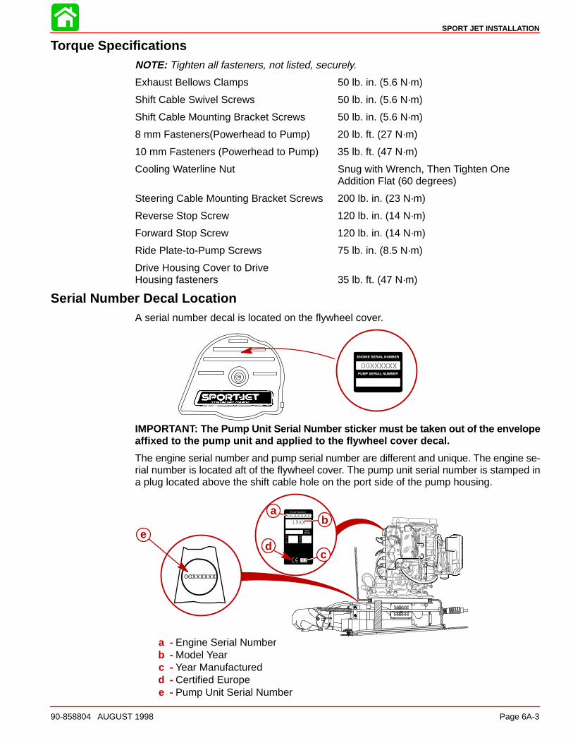
Serial Number Decal LocationA serial number decal is located on the flywheel cover.
OGXXXXXX
IMPORTANT: The Pump Unit Serial Number sticker must be taken out of the envelopeaffixed to the pump unit and applied to the flywheel cover decal.
The engine serial number and pump serial number are different and unique. The engine se-rial number is located aft of the flywheel cover. The pump unit serial number is stamped ina plug located above the shift cable hole on the port side of the pump housing.
19XX
XX
OGXXXXXXa
b
cd
e
a - Engine Serial Numberb - Model Yearc - Year Manufacturedd - Certified Europee - Pump Unit Serial Number

SPORT JET INSTALLATION
Page 6A-4 90-858804 AUGUST 1998
Corrosion ProtectionThis power package is equipped with anodes to help protect it from galvanic corrosion undermoderate conditions. See the Operator’s Manual for location of anodes.
Installation RequirementsIMPORTANT: The Sport Jet is considered an INBOARD engine. The boat it is installedin must meet industry standards (ABYC, NMMA, etc.), federal standards and CoastGuard regulations for INBOARD engine installations
Battery/Battery CablesIMPORTANT: Boating industry standards (ABYC, NMMA, etc.), federal standards andCoast Guard regulations must be adhered to when installing battery. Be sure batterycable installation meets the pull test requirements and that positive battery terminalis properly insulated in accordance with regulations.
IMPORTANT: Engine electrical system is negative (–) ground. It is recommended (re-quired in some states) that battery be installed in an enclosed case. Refer to regula-tions for your area.
1. Select a battery that meets all of the following specifications:
a. 12-volt marine type.
b. 670 Marine Cranking Amps (MCA) or 520 Cold Cranking Amps (CCA).
c. Reserve capacity rating of at least 100 minutes.
2. Select proper size positive (+) and negative (–) battery cables using chart. Batteryshould be located as close to engine as possible.
IMPORTANT: Terminals must be soldered to cable ends to ensure good electricalcontact. Use electrical grade (resin flux) solder only. Do not use acid flux solder, asit may cause corrosion and a subsequent failure.
Cable Length Cable Gauge
Up to 3-1/2 ft. (1.1 m) 4 (25 mm2)
3-1/2 - 6 ft. (1.1-1.8 m) 2 (35 mm2)
6 - 7-1/2 ft. (1.8-2.3 m) 1 (50 mm2)
7-1/2 - 9-1/2 ft. (2.3-2.9 m) 0 (50 mm2)
9-1/2 - 12 ft. (2.9-3.7 m) 00 (70 mm2)
12 - 15 ft. (3.7-4.6 m) 000 (95 mm2)
15 - 19 ft. (4.6-5.8 m) 0000 (120 mm2)
Boat ConstructionIMPORTANT: All applicable Coast Guard regulations for INBOARD engines must becomplied with, when constructing engine compartment.
Care must be exercised in the design and construction of the engine compartment. Seamsmust be located so that any rain water or splash, which may leak through the seams, is di-rected away from the engine and carburetor cover. Also, the passenger compartment drain-age system should not be routed directly to the engine compartment. Water that runs onor is splashed in the carburetor cover may enter the engine and cause serious dam-age to internal engine parts.
IMPORTANT: Mercury Marine will not honor any warranty claim for engine damageas a result of water entry.
SPORT JET INSTALLATION
90-858804 AUGUST 1998 Page 6A-5
Engine Compartment VentilationEngine compartment must be designed to provide a sufficient volume of air for enginebreathing and also must vent off any fumes in engine compartment in accordance withindustry standards (ABYC, NMMA, etc.), federal standards and Coast Guard regulations forinboard engines. Pressure differential (outside engine compartment versus inside enginecompartment) should not exceed 2 in. (51 mm) of water (measured with a manometer) atmaximum air flow rate.
Engine Compartment Specifications
Model Engine Air Requirements at Wide Open Throttle Physical EngineVolume*
95 HP 230 ft.3/min. (0.109m3/sec.) 0.60 ft.3 (17 L)
120 HP 304 ft.3/min. (0.143 m3/sec.) 0.67 ft.3 (19 L)
* Physical engine volume is used in flotation calculations and is representative of the amountof flotation the engine provides.
For serviceability, it is recommended that an additional 6 inches minimum (152 mm) (perside) of clearance be allowed between powerhead and engine compartment walls.
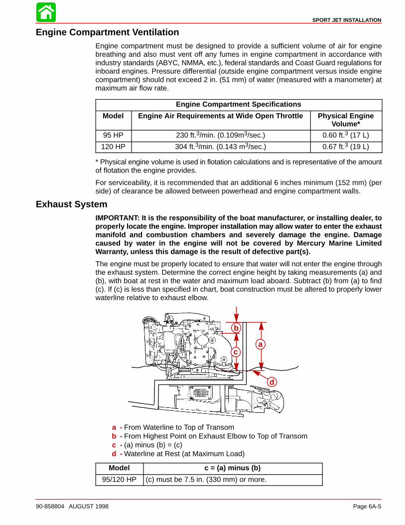
Exhaust SystemIMPORTANT: It is the responsibility of the boat manufacturer, or installing dealer, toproperly locate the engine. Improper installation may allow water to enter the exhaustmanifold and combustion chambers and severely damage the engine. Damagecaused by water in the engine will not be covered by Mercury Marine LimitedWarranty, unless this damage is the result of defective part(s).
The engine must be properly located to ensure that water will not enter the engine throughthe exhaust system. Determine the correct engine height by taking measurements (a) and(b), with boat at rest in the water and maximum load aboard. Subtract (b) from (a) to find(c). If (c) is less than specified in chart, boat construction must be altered to properly lowerwaterline relative to exhaust elbow.
a
b
c
d
a - From Waterline to Top of Transomb - From Highest Point on Exhaust Elbow to Top of Transomc - (a) minus (b) = (c)d - Waterline at Rest (at Maximum Load)
Model c = (a) minus (b)
95/120 HP (c) must be 7.5 in. (330 mm) or more.
SPORT JET INSTALLATION
Page 6A-6 90-858804 AUGUST 1998
Fuel Delivery System
WARNINGBoating standards (NMMA, ABYC, etc.), federal standards and U. S. Coast Guardregulations for INBOARD engines must be adhered to when installing fuel deliverysystem. Failure to comply could result in severe personal injury or death.
CAUTIONRemove plastic plug from fuel inlet fitting. Attach fuel line to fuel fitting with U.S.Coast Guard approved hose clamp. Inspect for fuel leaks.
1. Fuel tank should be mounted below carburetor(s) level (if possible) or gravity feed maycause carburetor fuel inlet needle(s) to unseat, and flooding may result.
2. Fuel pickup should be at least 1 in. (25 mm) from the bottom of the fuel tank to preventpicking up impurities.
3. Fuel lines used must be Coast Guard approved (USCG type A1), fittings and lines mustnot be smaller than 5/16 in. (8 mm) I.D.
4. On installations requiring long lines or numerous fittings, larger size lines should beused.
5. Fuel line should be installed free of stress and firmly secured to prevent vibration and/orchafing.
6. Sharp bends in fuel line should be avoided.
7. A flexible fuel line must be used to connect fuel line to engine fuel pump to absorb deflec-tion when engine is running.
8. A primer bulb is not necessary with this application. If a primer bulb is used, it must beCoast Guard approved for inboard engine applications.
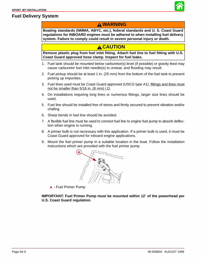
9. Mount the fuel primer pump in a suitable location in the boat. Follow the installationinstructions which are provided with the fuel primer pump.
a
a - Fuel Primer Pump
IMPORTANT: Fuel Primer Pump must be mounted within 12 ” of the powerhead perU.S. Coast Guard regulation.

SPORT JET INSTALLATION
90-858804 AUGUST 1998 Page 6A-7
Instrumentation
CAUTIONIf a fused accessory panel is to be used, it is recommended that a separate circuit(properly fused) be used from the battery to the fuse panel with sufficient wire sizeto handle the intended current load.
NOTE: The charging system on these engines is capable of producing 9 amps maximumcharge at 3500 RPM (4.5 amps minimum at 1000 RPM). The electrical load of the boatshould not exceed this capacity. If loads higher than the capacity of the charging system areanticipated, refer to “Quicksilver Accessory Guide” for a high output alternator.
We recommend the use of Quicksilver Instrumentation and Wiring Harness(es). Refer to“Quicksilver Accessories Guide” for selection.
If other than Quicksilver electrical accessories are to be used, it is good practice to usewaterproof ignition components (ignition switch, lanyard stop switch, etc.). A typical jet boatof this nature will see water splashed on these components. Therefore, precautions mustbe taken to avoid ignition failure due to shorting out of ignition components.
WARNINGSudden stopping of engine (shorting ignition components) while boat is underwaywill cause loss of steering control due to loss of thrust. This loss of steering controlmay cause property damage, personal injury or death.
A warning horn must be incorporated in the wiring harness (see wiring diagram) to alert theuser of an overheat or low oil condition.
IMPORTANT: If a warning horn system is not installed by the boat manufacturer, Mer-cury Marine will not honor any warranty claims for engine damage as a result of over-heating or lack of engine oil.
Route instrumentation wiring harness back to engine, making sure that harness does notrub or get pinched. If an extension harness is required, be sure to secure connection proper-ly. Fasten harness(es) to boat at least every 18 in. (460 mm), using appropriate fasteners.
SPORT JET INSTALLATION
Page 6A-8 90-858804 AUGUST 1998
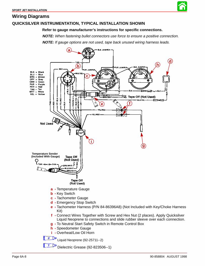
Wiring DiagramsQUICKSILVER INSTRUMENTATION, TYPICAL INSTALLATION SHOWN
Refer to gauge manufacturer’s instructions for specific connections.
NOTE: When fastening bullet connectors use force to ensure a positive connection.
NOTE: If gauge options are not used, tape back unused wiring harness leads.
(Included With Gauge)Temperature Sender
i
a
b
c
d
e f
g
h
i
a - Temperature Gaugeb - Key Switchc - Tachometer Gauged - Emergency Stop Switche - Tachometer Harness (P/N 84-86396A8) (Not Included with Key/Choke Harness
Kit)f - Connect Wires Together with Screw and Hex Nut (2 places). Apply Quicksilver
Liquid Neoprene to connections and slide rubber sleeve over each connection.g - To Neutral Start Safety Switch in Remote Control Boxh - Speedometer Gaugei - Overheat/Low Oil Horn
P Liquid Neoprene (92-25711--2)
T Dielectric Grease (92-823506--1)
SPORT JET INSTALLATION
90-858804 AUGUST 1998 Page 6A-9
Impeller SelectionIMPORTANT: Installed i mpeller must allow engine to run in its specified maximum wi-de-open-throttle RPM range.
The jet drive comes equipped with a standard stainless steel impeller which allows theengine to operate in its specified operating range.
If a different impeller is installed in place of the standard impeller, it is the responsibility ofthe installer to ensure engine RPM remains in specified range. Specified engine WOT RPMrange is listed in “Operation and Maintenance Manual” attached to the engine.
Remote Control and CablesTo ensure proper shift and throttle operation, we recommend the use of the Sport Jet Re-mote Control (P/N 802755). This remote control has been qualified by Mercury Marine tobe used with the Sport Jet and provides the following required features:
• Start-in-gear protection
• Neutral rpm limit at 2,000 rpm
NOTE: This applies to dual lever remote controls as well as single lever remote controls
• High strength mechanism to accommodate loads transmitted to the remote control
• Shift cable travel of 3 inches �1/8 inch (76 mm �3 mm)
• Ability to use 40 series shift cable
If a remote control other than the Sport Jet Remote Control (P/N 802755) is used, the remotecontrol must meet the above criteria as well as the design criteria outlined in the ABYCmanual pertaining to Mini-Jet Boats (Standard P-23).
SHIFT CABLE
The shift cable to be used MUST MEET the following criteria:
• 40-Series Cable
• Allow for a minimum of 3 inches (76 mm) of travel.
• A means of attaching and locking the cable to the wear ring.
• Cable end at pump must allow for a clevis pin and cotter pin (all provided) to connectcable to the reverse gate.
• Protected against water intrusion and/or corrosion as the cable end (at the pump) is sub-mersed in water with the boat at rest.
A cable bellows is provided with the cable (P/N 64-858342A_). Follow installation proce-dures for proper sealing of cable.
The shift cable end (at the pump) is submersed in water. It should be sealed against waterintrusion, protected against corrosion and be able to withstand the shift loads imparted onit by the reverse gate.
Follow shift cable adjustment procedure for proper adjustment.
THROTTLE CABLE
The throttle cable must have one end compatible with the control box. The other end musthave Mercury style connectors.
Follow throttle cable adjustment procedures for proper adjustment.
http://motorka.org
SPORT JET INSTALLATION
Page 6A-10 90-858804 AUGUST 1998
Steering Helm and CableSTEERING HELM
The steering helm must limit steering cable travel to 3.50 ± .10 inches (88.9 ± 2.5 mm).
WARNINGFailure to limit steering cable travel at the helm could pre-load the cable resultingin premature failure of a steering component causing loss of steering. This loss ofsteering could cause property damage, personal injury or death.
STEERING CABLE
The steering cable to be used MUST MEET the following criteria:
• 60 Series Steering Cable
• 60 Series bulkhead fitting at output end
• Allow for a minimum of 3.75 inches (95.3 mm) of travel.
• Cable end at pump must allow for a 5/16 in. threaded adaptor shouldered thru-bolt andlock nut to connect the cable to the steering arm.
• A means of attaching and locking the cable to the steering cable bracket (provided).
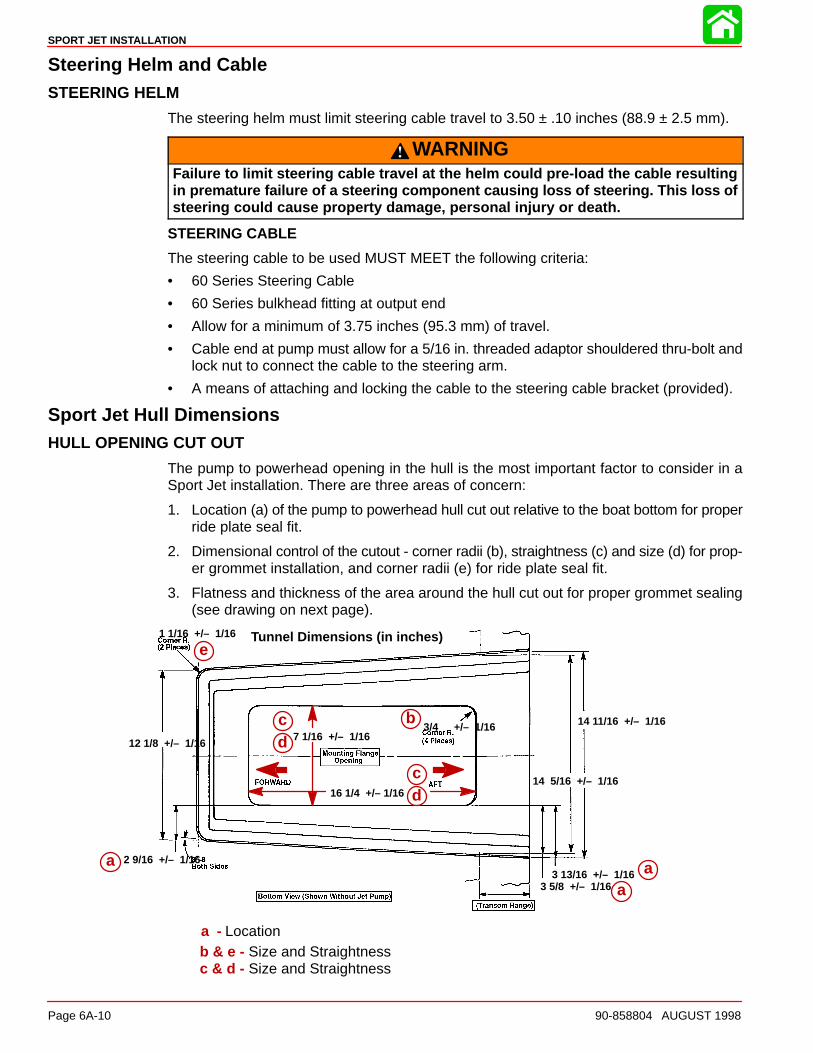
Sport Jet Hull DimensionsHULL OPENING CUT OUT
The pump to powerhead opening in the hull is the most important factor to consider in aSport Jet installation. There are three areas of concern:
1. Location (a) of the pump to powerhead hull cut out relative to the boat bottom for properride plate seal fit.
2. Dimensional control of the cutout - corner radii (b), straightness (c) and size (d) for prop-er grommet installation, and corner radii (e) for ride plate seal fit.
3. Flatness and thickness of the area around the hull cut out for proper grommet sealing(see drawing on next page).
1 1/16 +/– 1/16
3/4 +/– 1/167 1/16 +/– 1/16
16 1/4 +/– 1/16
14 11/16 +/– 1/16
14 5/16 +/– 1/16
2 9/16 +/– 1/16
12 1/8 +/– 1/16
3 13/16 +/– 1/163 5/8 +/– 1/16
Tunnel Dimensions (in inches)
a
e
aa
cd
cd
b
a - Locationb & e - Size and Straightnessc & d - Size and Straightness
SPORT JET INSTALLATION
90-858804 AUGUST 1998 Page 6A-11
METHODS OF CONTROLLING LOCATION AND SIZE
If the tunnel area in the plug is correct, the boat bottom mold should repeat and reproducethe tunnel area which will aid the cut out process.
A reference area for the cut out can be produced on the plug and bottom mold as a raisedarea or a cutting guide.
Location pins (a) that would project into the internal hull area could simplify the cut outprocess.
These location pin holes could allow the use of a 1-1/2 inch diameter hole saw to cut thefour corner radii and use of a reciprocating saw or router template to connect the fourholes.
Mounting Flange ThicknessSpecifications
1 Inch Minimum Flange Width
Recommended Flange Flatness: .030 Inch Maximum Between Reference Points
AA
Section A-A
1/2
1/2
1/2
1/2
1 1/2 Inch Dia. Hole Saw
GO NO GO
Max. Size Min. Size
1/2” +0.070–0.030
1/4” +0.050–0.030
3/8”+0.050–0.030
Use Grommet P/N:
25-820663-250
25-820663-375
25-820663-500
b
a
a
a
a
c
a - Location Pins in Hull Moldb - Flange Flatness Specificationc - Go – No Go Gauge for Thickness
CHECKING MOUNTING FLANGE THICKNESS AND FLATNESS
Use a flat plate that will contact the flange at the reference points (b) and a .030 in. feelergauge to check flatness.
Additional sanding and/or resin / filler may be required to maintain the flatness specification.
A simple slotted go / no go gauge (c) will check the flange thickness.
SPORT JET INSTALLATION
Page 6A-12 90-858804 AUGUST 1998
Installing Jet Pump
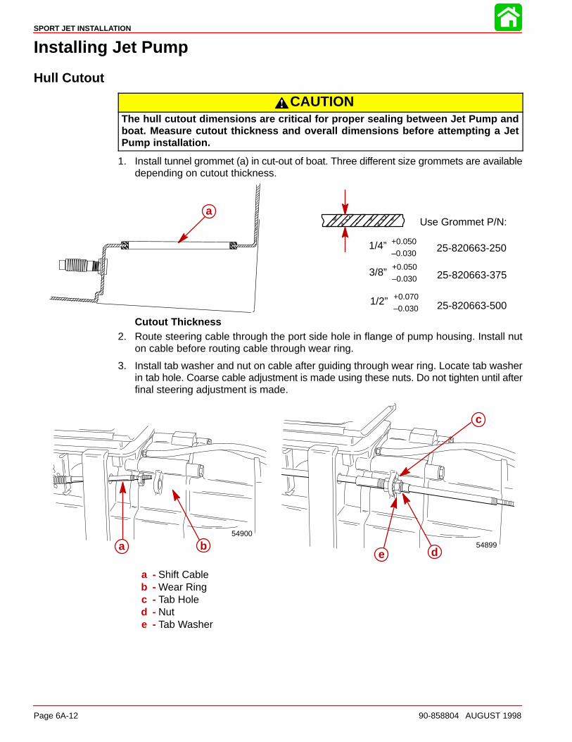
Hull Cutout
CAUTIONThe hull cutout dimensions are critical for proper sealing between Jet Pump andboat. Measure cutout thickness and overall dimensions before attempting a JetPump installation.
1. Install tunnel grommet (a) in cut-out of boat. Three different size grommets are availabledepending on cutout thickness.
ÀÀÀÀÀÀÀÀÀÀÀÀÀÀÀÀÀÀÀÀÀÀÀÀÀÀ
1/2” +0.070
–0.030
1/4” +0.050
–0.030
3/8” +0.050
–0.030
Use Grommet P/N:
25-820663-250
25-820663-375
25-820663-500
a
Cutout Thickness2. Route steering cable through the port side hole in flange of pump housing. Install nut
on cable before routing cable through wear ring.
3. Install tab washer and nut on cable after guiding through wear ring. Locate tab washerin tab hole. Coarse cable adjustment is made using these nuts. Do not tighten until afterfinal steering adjustment is made.
54899
c
de
54900
a ba b
c
de
a - Shift Cableb - Wear Ringc - Tab Holed - Nute - Tab Washer
SPORT JET INSTALLATION
90-858804 AUGUST 1998 Page 6A-13
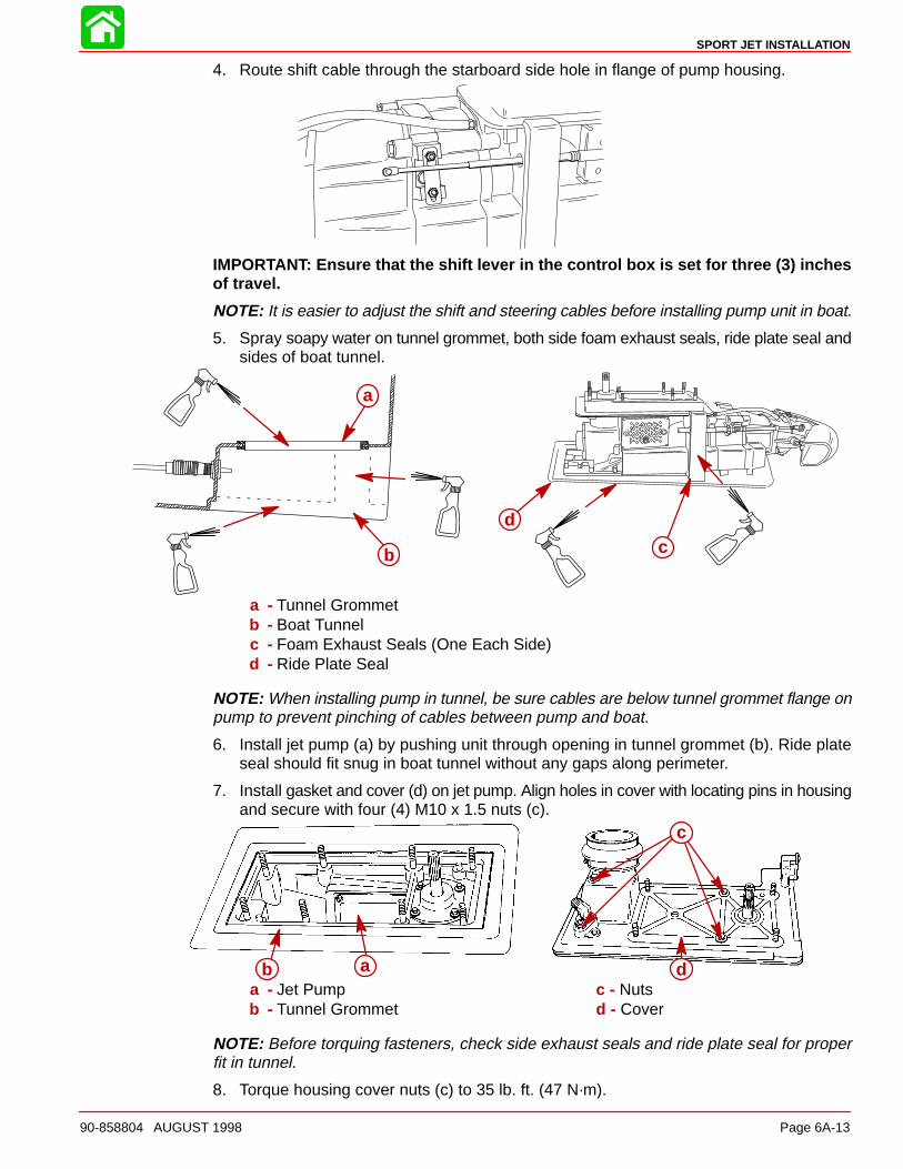
4. Route shift cable through the starboard side hole in flange of pump housing.
IMPORTANT: Ensure that the shift lever in the control box is set for three (3) inchesof travel.
NOTE: It is easier to adjust the shift and steering cables before installing pump unit in boat.
5. Spray soapy water on tunnel grommet, both side foam exhaust seals, ride plate seal andsides of boat tunnel.
d
cb
a
a - Tunnel Grommetb - Boat Tunnelc - Foam Exhaust Seals (One Each Side)d - Ride Plate Seal
NOTE: When installing pump in tunnel, be sure cables are below tunnel grommet flange onpump to prevent pinching of cables between pump and boat.
6. Install jet pump (a) by pushing unit through opening in tunnel grommet (b). Ride plateseal should fit snug in boat tunnel without any gaps along perimeter.
7. Install gasket and cover (d) on jet pump. Align holes in cover with locating pins in housingand secure with four (4) M10 x 1.5 nuts (c).
ab d
c
a - Jet Pump c - Nutsb - Tunnel Grommet d - Cover
NOTE: Before torquing fasteners, check side exhaust seals and ride plate seal for properfit in tunnel.
8. Torque housing cover nuts (c) to 35 lb. ft. (47 N·m).
SPORT JET INSTALLATION
Page 6A-14 90-858804 AUGUST 1998
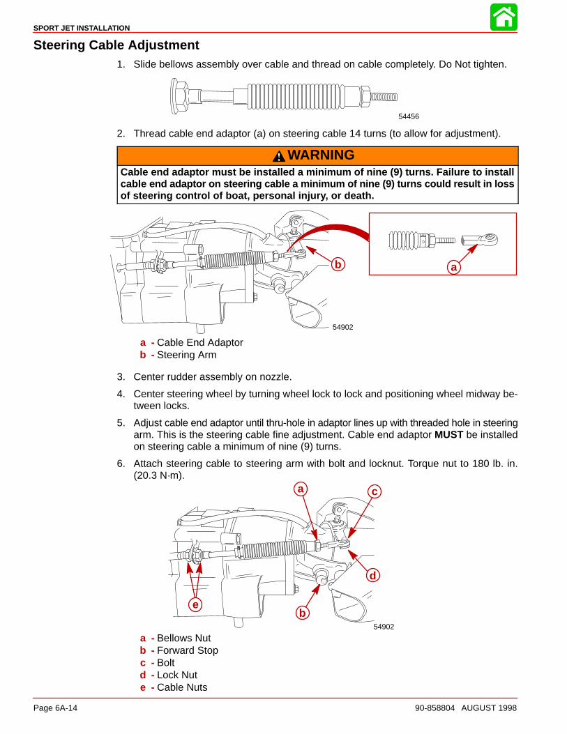
Steering Cable Adjustment1. Slide bellows assembly over cable and thread on cable completely. Do Not tighten.
54456
2. Thread cable end adaptor (a) on steering cable 14 turns (to allow for adjustment).
WARNINGCable end adaptor must be installed a minimum of nine (9) turns. Failure to installcable end adaptor on steering cable a minimum of nine (9) turns could result in lossof steering control of boat, personal injury, or death.
54902
ab
a - Cable End Adaptorb - Steering Arm
3. Center rudder assembly on nozzle.
4. Center steering wheel by turning wheel lock to lock and positioning wheel midway be-tween locks.
5. Adjust cable end adaptor until thru-hole in adaptor lines up with threaded hole in steeringarm. This is the steering cable fine adjustment. Cable end adaptor MUST be installedon steering cable a minimum of nine (9) turns.
6. Attach steering cable to steering arm with bolt and locknut. Torque nut to 180 lb. in.(20.3 N·m).
54902
b
c
d
e
a
b
c
d
e
a - Bellows Nutb - Forward Stopc - Boltd - Lock Nute - Cable Nuts
SPORT JET INSTALLATION
90-858804 AUGUST 1998 Page 6A-15
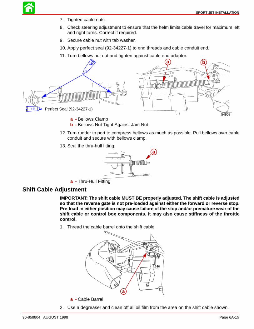
7. Tighten cable nuts.
8. Check steering adjustment to ensure that the helm limits cable travel for maximum leftand right turns. Correct if required.
9. Secure cable nut with tab washer.
10. Apply perfect seal (92-34227-1) to end threads and cable conduit end.
11. Turn bellows nut out and tighten against cable end adaptor.
54908
19
Perfect Seal (92-34227-1)19
ba
a - Bellows Clampb - Bellows Nut Tight Against Jam Nut
12. Turn rudder to port to compress bellows as much as possible. Pull bellows over cableconduit and secure with bellows clamp.
13. Seal the thru-hull fitting.a
a - Thru-Hull Fitting
Shift Cable AdjustmentIMPORTANT: The shift cable MUST BE properly adjusted. The shift cable is adjustedso that the reverse gate is not pre-loaded against either the forward or reverse stop.Pre-load in either position may cause failure of the stop and/or premature wear of theshift cable or control box components. It may also cause stiffness of the throttlecontrol.
1. Thread the cable barrel onto the shift cable.
aa
a - Cable Barrel
2. Use a degreaser and clean off all oil film from the area on the shift cable shown.
SPORT JET INSTALLATION
Page 6A-16 90-858804 AUGUST 1998
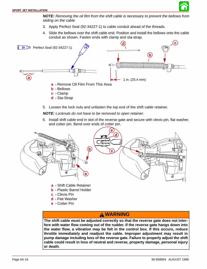
NOTE: Removing the oil film from the shift cable is necessary to prevent the bellows fromsliding on the cable.
3. Apply Perfect Seal (92-34227-1) to cable conduit ahead of the threads.
4. Slide the bellows over the shift cable end. Position and install the bellows onto the cableconduit as shown. Fasten ends with clamp and sta-strap.
1 in. (25.4 mm)
b
cd
a
19Perfect Seal (92-34227-1)19
a
a - Remove Oil Film From This Areab - Bellowsc - Clampd - Sta-Strap
5. Loosen the lock nuts and unfasten the top end of the shift cable retainer.
NOTE: Locknuts do not have to be removed to open retainer.
6. Install shift cable end in slot of the reverse gate and secure with clevis pin, flat washer,and cotter pin. Bend over ends of cotter pin.
a
c
de
a
b
a - Shift Cable Retainerb - Plastic Barrel Holderc - Clevis Pind - Flat Washere - Cotter Pin
WARNINGThe shift cable must be adjusted correctly so that the reverse gate does not inter-fere with water flow coming out of the rudder. If the reverse gate hangs down intothe water flow, a vibration may be felt in the control box. If this occurs, reducethrottle immediately and readjust the cable. Improper adjustment may result inpump damage including loss of the reverse gate. Failure to properly adjust the shiftcable could result in loss of neutral and reverse, property damage, personal injuryor death.
SPORT JET INSTALLATION
90-858804 AUGUST 1998 Page 6A-17
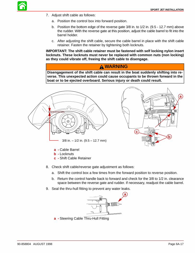
7. Adjust shift cable as follows:
a. Position the control box into forward position.
b. Position the bottom edge of the reverse gate 3/8 in. to 1/2 in. (9.5 - 12.7 mm) abovethe rudder. With the reverse gate at this position, adjust the cable barrel to fit into thebarrel holder.
c. After adjusting the shift cable, secure the cable barrel in place with the shift cableretainer. Fasten the retainer by tightening both locknuts.
IMPORTANT: The shift cable retainer must be fastened with self locking nylon insertlocknuts. These locknuts must never be replaced with common nuts (non locking)as they could vibrate off, freeing the shift cable to disengage.
WARNINGDisengagement of the shift cable can result in the boat suddenly shifting into re-verse. This unexpected action could cause occupants to be thrown forward in theboat or to be ejected overboard. Serious injury or death could result.
3/8 in. – 1/2 in. (9.5 – 12.7 mm)
a
bc
a
bc
a - Cable Barrelb - Locknutsc - Shift Cable Retainer
8. Check shift cable/reverse gate adjustment as follows:
a. Shift the control box a few times from the forward position to reverse position.
b. Return the control handle back to forward and check for the 3/8 to 1/2 in. clearancespace between the reverse gate and rudder. If necessary, readjust the cable barrel.
9. Seal the thru-hull fitting to prevent any water leaks.
a
a - Steering Cable Thru-Hull Fitting
SPORT JET INSTALLATION
Page 6A-18 90-858804 AUGUST 1998
Bilge Siphon Feature
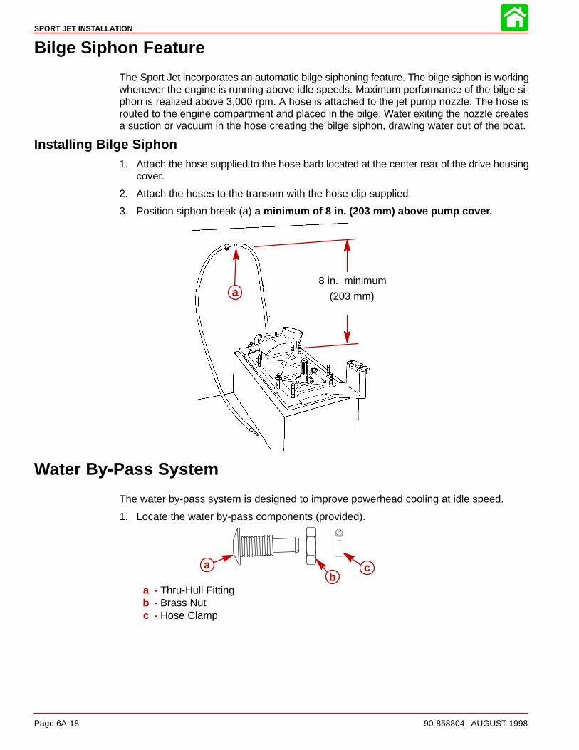
The Sport Jet incorporates an automatic bilge siphoning feature. The bilge siphon is workingwhenever the engine is running above idle speeds. Maximum performance of the bilge si-phon is realized above 3,000 rpm. A hose is attached to the jet pump nozzle. The hose isrouted to the engine compartment and placed in the bilge. Water exiting the nozzle createsa suction or vacuum in the hose creating the bilge siphon, drawing water out of the boat.
Installing Bilge Siphon1. Attach the hose supplied to the hose barb located at the center rear of the drive housing
cover.
2. Attach the hoses to the transom with the hose clip supplied.
3. Position siphon break (a) a minimum of 8 in. (203 mm) above pump cover.
8 in. minimum
(203 mm)aa
Water By-Pass System
The water by-pass system is designed to improve powerhead cooling at idle speed.
1. Locate the water by-pass components (provided).
cb
aab
c
a - Thru-Hull Fittingb - Brass Nutc - Hose Clamp
SPORT JET INSTALLATION
90-858804 AUGUST 1998 Page 6A-19
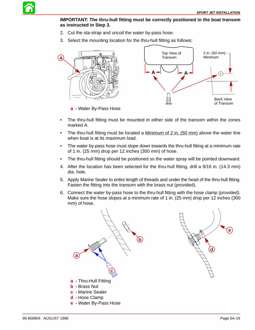
IMPORTANT: The thru-hull fitting must be correctly positioned in the boat transomas instructed in Step 3.
2. Cut the sta-strap and uncoil the water by-pass hose.
3. Select the mounting location for the thru-hull fitting as follows:
A
2 in. (50 mm) Minimum
Top View ofTransom
A
Back Viewof Transom
aa
a - Water By-Pass Hose
• The thru-hull fitting must be mounted in either side of the transom within the zonesmarked A.
• The thru-hull fitting must be located a Minimum of 2 in. (50 mm) above the water linewhen boat is at its maximum load.
• The water by-pass hose must slope down towards the thru-hull fitting at a minimum rateof 1 in. (25 mm) drop per 12 inches (300 mm) of hose.
• The thru-hull fitting should be positioned so the water spray will be pointed downward.
4. After the location has been selected for the thru-hull fitting, drill a 9/16 in. (14.3 mm)dia. hole.
5. Apply Marine Sealer to entire length of threads and under the head of the thru-hull fitting.Fasten the fitting into the transom with the brass nut (provided).
6. Connect the water by-pass hose to the thru-hull fitting with the hose clamp (provided).Make sure the hose slopes at a minimum rate of 1 in. (25 mm) drop per 12 inches (300mm) of hose.
d
e
a
b
c
a
b
c
a - Thru-Hull Fittingb - Brass Nutc - Marine Sealerd - Hose Clampe - Water By-Pass Hose
SPORT JET INSTALLATION
Page 6A-20 90-858804 AUGUST 1998
Installing Powerhead
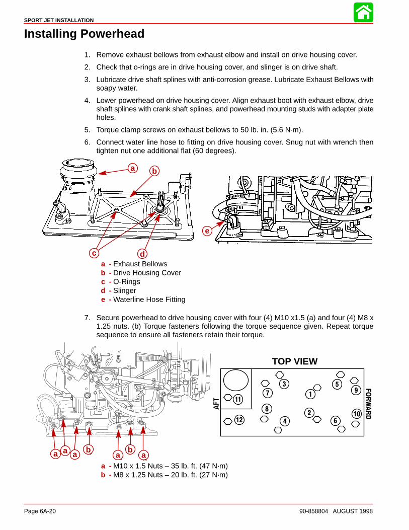
1. Remove exhaust bellows from exhaust elbow and install on drive housing cover.
2. Check that o-rings are in drive housing cover, and slinger is on drive shaft.
3. Lubricate drive shaft splines with anti-corrosion grease. Lubricate Exhaust Bellows withsoapy water.
4. Lower powerhead on drive housing cover. Align exhaust boot with exhaust elbow, driveshaft splines with crank shaft splines, and powerhead mounting studs with adapter plateholes.
5. Torque clamp screws on exhaust bellows to 50 lb. in. (5.6 N·m).
6. Connect water line hose to fitting on drive housing cover. Snug nut with wrench thentighten nut one additional flat (60 degrees).
e
a
c
b
d
a b
c da - Exhaust Bellowsb - Drive Housing Coverc - O-Ringsd - Slingere - Waterline Hose Fitting
7. Secure powerhead to drive housing cover with four (4) M10 x1.5 (a) and four (4) M8 x1.25 nuts. (b) Torque fasteners following the torque sequence given. Repeat torquesequence to ensure all fasteners retain their torque.
1
2
3
4
5
6
7
8
9
10
11
12
TOP VIEW
FORWARD
AFT
a baa
baaa a a a a
b b
a - M10 x 1.5 Nuts – 35 lb. ft. (47 N·m)b - M8 x 1.25 Nuts – 20 lb. ft. (27 N·m)
SPORT JET INSTALLATION
90-858804 AUGUST 1998 Page 6A-21
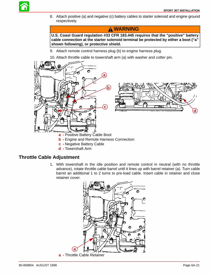
8. Attach positive (a) and negative (c) battery cables to starter solenoid and engine groundrespectively.
WARNINGU.S. Coast Guard regulation #33 CFR 183.445 requires that the “positive” batterycable connection at the starter solenoid terminal be protected by either a boot (“a”shown following), or protective shield.
9. Attach remote control harness plug (b) to engine harness plug.
10. Attach throttle cable to towershaft arm (a) with washer and cotter pin.
d
a
b
c
a - Positive Battery Cable Bootb - Engine and Remote Harness Connectionc - Negative Battery Cabled - Towershaft Arm
Throttle Cable Adjustment1. With towershaft in the idle position and remote control in neutral (with no throttle
advance), rotate throttle cable barrel until it lines up with barrel retainer (a). Turn cablebarrel an additional 1 to 2 turns to pre-load cable. Insert cable in retainer and closeretainer cover.
aa - Throttle Cable Retainer

SPORT JET INSTALLATION
Page 6A-22 90-858804 AUGUST 1998
Battery ConnectionNOTE: Engine electrical system is negative (–) ground.
1. Connect engine positive (+) battery cable (usually red) to positive (+) battery terminal.
2. Connect engine negative (–) battery cable (usually black) to negative (–) battery termi-nal.
3. Make sure that all battery terminal connections are tight; then, spray terminals with abattery connection sealant to help retard corrosion.
4. Some states require that the positive battery terminal be properly insulated.
Oil Injection SystemIMPORTANT: The oil injection system is setup and bled at the factory. Bleed only ifair bubble are present in the oil line from the reservoir to the oil pump.
1. Cut the sta-straps that are temporarily holding the oil reservoir to the engine.
2. Uncoil the oil line. Select a mounting location in the boat for the oil reservoir that is inreach of the oil hose and where the bottom on the reservoir is higher than the oil pump.Mount the oil reservoir.
baa
a - Oil Reservoirb - Bottom of Reservoir Must Be Higher Than the Oil Pump
IMPORTANT: Oil Reservoir must be mounted higher than the oil pump. Oil is gravityfed to the oil pump.
3. Follow the oil line from the reservoir to the oil pump. There should be no air in the line.If air is present, loosen bleed screw (c) and bleed air out until oil is present. Tighten bleedscrew.
ac
b
a
b
c
a - Oil Inlet Hoseb - Oil Outlet Hosec - Bleed Screw
SPORT JET INSTALLATION
90-858804 AUGUST 1998 Page 6A-23
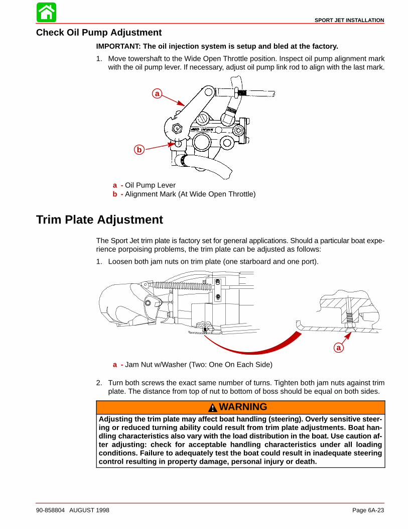
Check Oil Pump AdjustmentIMPORTANT: The oil injection system is setup and bled at the factory.
1. Move towershaft to the Wide Open Throttle position. Inspect oil pump alignment markwith the oil pump lever. If necessary, adjust oil pump link rod to align with the last mark.
a
b
a
b
a - Oil Pump Leverb - Alignment Mark (At Wide Open Throttle)
Trim Plate Adjustment
The Sport Jet trim plate is factory set for general applications. Should a particular boat expe-rience porpoising problems, the trim plate can be adjusted as follows:
1. Loosen both jam nuts on trim plate (one starboard and one port).
a
a - Jam Nut w/Washer (Two: One On Each Side)
2. Turn both screws the exact same number of turns. Tighten both jam nuts against trimplate. The distance from top of nut to bottom of boss should be equal on both sides.
WARNINGAdjusting the trim plate may affect boat handling (steering). Overly sensitive steer-ing or reduced turning ability could result from trim plate adjustments. Boat han-dling characteristics also vary with the load distribution in the boat. Use caution af-ter adjusting: check for acceptable handling characteristics under all loadingconditions. Failure to adequately test the boat could result in inadequate steeringcontrol resulting in property damage, personal injury or death.

SPORT JET INSTALLATION
Page 6A-24 90-858804 AUGUST 1998
Pre-delivery Inspection
Not Check/Applicable Adjust
Check Before Running
� � Water hose connection/torqued
� � Cover plate & adaptor plate fasteners torqued
� � Battery charged & secure
� � All electrical connections tight
� � Exhaust hose clamps tight
� � All fuel connections tight
� � Throttle, shift, & steering adjusted correctly and fasteners torqued
� � Carb throttle shutters open & close completely
� � Pump housing oil level full (See Owner’s Manual)
� � Oil injection reservoir full and bled
� � Warning system(s) operational
On the Water Test
� � Starter neutral safety switch operational
� � Lanyard stop switch operational
� � All gauges read properly
� � No fuel or oil leaks
� � No water leaks
� � No exhaust leaks
� � Ignition timing set to specs
� � Idle:____________RPM
� � Idle mixture adjusted
� � Forward-Neutral-Reverse operational
� � Steering operational throughout entire range
� � Acceleration test
� � WOT:___________RPM
� � Boat handling
Post Water Test
� � No fuel, oil, water or exhaust leaks
� � Re-torque adapter plate fasteners


