
Seeing Beyond the Visible
Doug Malchow Manager, Industrial Business
Development Sensors Unlimited, Inc
UTC Aerospace Systems This document does not contain Export Controlled technology or technical data X-Class registered under CLS06339866

Outline
• What is imaging? (If you can’t see it, does it still exist?) • What enables imaging: The Electromagnetic spectrum • Imaging band descriptions and examples
– Gamma radiation – X-ray radiation – Ultraviolet radiation – Visible radiation – Infrared radiation and sub-bands of NIR, SWIR, MWIR and LWIR
• SWIR Imaging – Why use? – Where used?
• Application examples
• Summary

What is Imaging in any Band?
• Making a visual representation of an object by scanning it with detector(s) or electromagnetic beam(s), or by passing an object between detector(s) and beam(s).
• It is a function of the object modifying the energy by passing, absorbing, reflecting or scattering the beam(s) resulting in creating a difference map for display for a human to view or for a computer to analyze
• The recorded differences are relative and influenced by everything in the beam path – The energy source, – The medium it passes through to get to object, – The object being imaged, which effects
the beam. – The medium the energy passes to get to the
detector, – The elements used to collect or focus – The detector
• These influences can be calibrated to take out non-uniformities or to measure the energy in absolute units
http://en.m.wikipedia.org/wiki/Photofragment-ion_imaging

Energy Source Emits
Image courtesy of ESA / AOES Mediala Microsoft clip art

Interacts with Stuff
• The energy is: – Reflected
• Specular • Diffuse
– Diffracted – Scattered, – Refracted (bent) – Absorbed
• Heat • Re-radiated • Selective λ
– Transmitted
http://missionscience.nasa.gov/ems/03_behaviors.html http:// marketplace.secondlife.com http://www.flickr.com/groups/strobist/discuss/72157600866439843/page2/
Refraction
Reflection
Scatter
Transmission
Reflections
Scatter
Diffuse Reflection
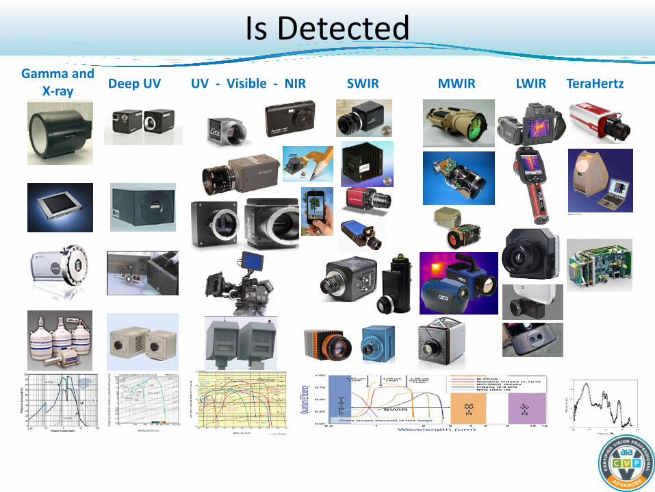
Gamma and X-ray Deep UV UV - Visible - NIR SWIR MWIR LWIR TeraHertz
Is Detected

Gamma and X-ray
Deep UV UV - Visible - NIR SWIR MWIR LWIR TeraHertz LWIR Senses Thermal Emissions SWIR Visible
Car paint Bruises Fingerprints
Is Displayed
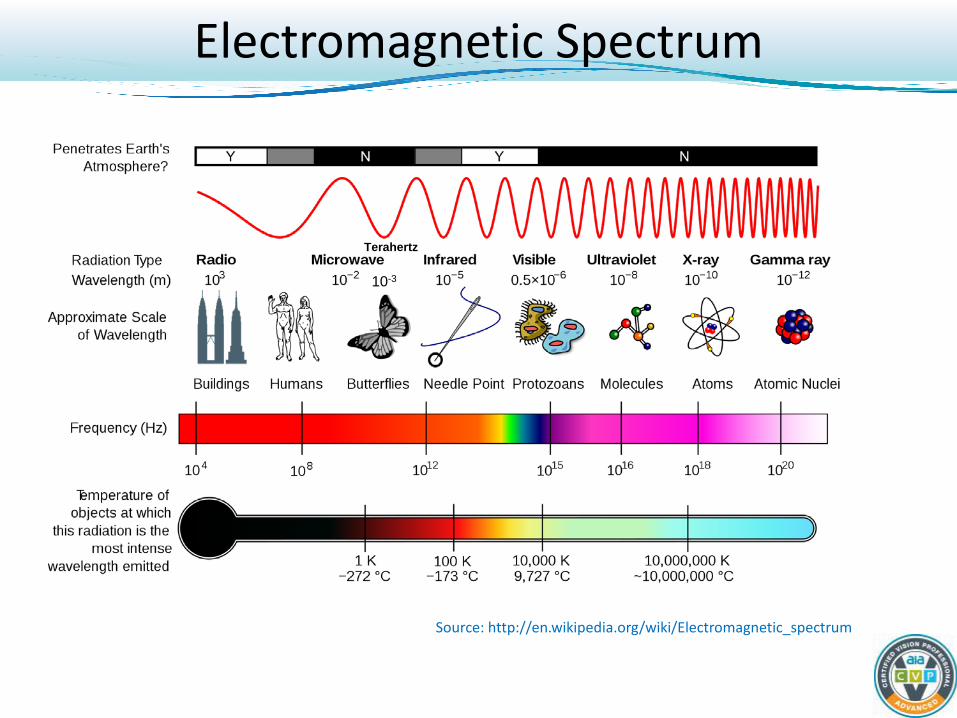
Source: http://en.wikipedia.org/wiki/Electromagnetic_spectrum
Terahertz
10-3
Electromagnetic Spectrum

• The most energetic photons, • Produced by radioisotopes • No defined lower wavelength
limit • Used for imaging by:
– Astronomers to study high-energy objects or regions
– Physicists due to the penetrative ability
– Doctors for PET scans • Isotope inside person emits
gamma ray • Scintillator converts to visible for
CCD
http://science.hq.nasa.gov/kids/imagers/ems/gamma_ray_sky.jpg http://en.wikipedia.org/wiki/Positron_emission_tomography
Gamma Rays
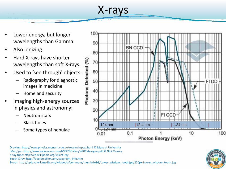
• Lower energy, but longer wavelengths than Gamma
• Also ionizing. • Hard X-rays have shorter
wavelengths than soft X-rays. • Used to ‘see through' objects:
– Radiography for diagnostic images in medicine
– Homeland security
• Imaging high-energy sources in physics and astronomy:
– Neutron stars – Black holes – Some types of nebulae
Drawing: http://www.physics.monash.edu.au/research/pcxi.html © Monash University Man/gun :http://www.nickveasey.com/NV%20Gallery%20Catalogue.pdf © Nick Veasey X-tay tube: http://en.wikipedia.org/wiki/X-ray Tooth X-ray: http://doctorspiller.com/copyright_info.htm Tooth: http://upload.wikimedia.org/wikipedia/commons/thumb/b/b8/Lower_wisdom_tooth.jpg/220px-Lower_wisdom_tooth.jpg
124 nm |12.4 nm | 1.24 nm | 0.124 nm
X-rays

• Shorter wavelength than violet light but longer than X-ray
• Therefore higher energy than violet, but less than X-rays
• Very energetic, UV rays can break chemical bonds, making molecules unusually reactive – capable even of ionizing atoms
• Images bacteria, melanin, fingerprints, UV coatings
• Induces fluorescence at longer (visible) wavelengths
http://www.stanford.edu/group/pandegroup/folding/education/papers/nature02.html http://www.uvcamera.com/Faraghan%20Medical%20Camera%20Systems/Welcome.html BI CCD QE © http://www.spectra-magic.de/E-Detectors.htm
UV Imaging
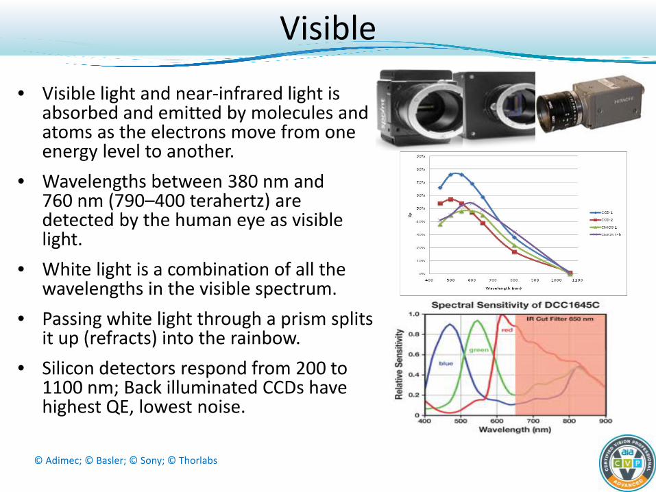
• Visible light and near-infrared light is absorbed and emitted by molecules and atoms as the electrons move from one energy level to another.
• Wavelengths between 380 nm and 760 nm (790–400 terahertz) are detected by the human eye as visible light.
• White light is a combination of all the wavelengths in the visible spectrum.
• Passing white light through a prism splits it up (refracts) into the rainbow.
• Silicon detectors respond from 200 to 1100 nm; Back illuminated CCDs have highest QE, lowest noise.
© Adimec; © Basler; © Sony; © Thorlabs
Visible

• Covers 750 nm to 1 mm (400 THz to 300 GHz) Subdivided into three sub-bands: – Near-infrared or Short-Wave Infrared, 750 to 2,500 nm or 0.75
to 2.5 µm (400 to 120 THz) • Photon interactions similar to visible light • Thermal emissions over 100 °C • Overtones (harmonics) of molecular vibrations absorb for remote
chemical ID – Mid-infrared, 2.5 to 10 μm (120 to 30 THz).
• Hot objects (black-body radiators) radiate strongly. • Chemical ID via absorbed due to fundamental frequency of molecule
vibrations – Far-infrared, 10 μm to 1 mm (30 THz to 300 GHz). The lower part
of this range may also be labeled Terahertz or microwaves. • absorbed by so-called rotational modes in gas-phase molecules, by
molecular motions in liquids, and by phonons in solids. • The water in Earth's atmosphere absorbs so strongly in this range that it
renders the atmosphere in effect opaque but with "windows") • in astronomy 200 μm up to a few mm aka "sub-millimeter", • 3 THz to 0.3 THz aka Terahertz band
© Willie Neumann © http://www.spectra-magic.de/E-Detectors.htm; Atmospheric spectrum credit: NASA/IPAC
Infrared
Thermal Micro-bolometers below dashed black curve ↓↓

Images © FLIR
Infrared - Thermal
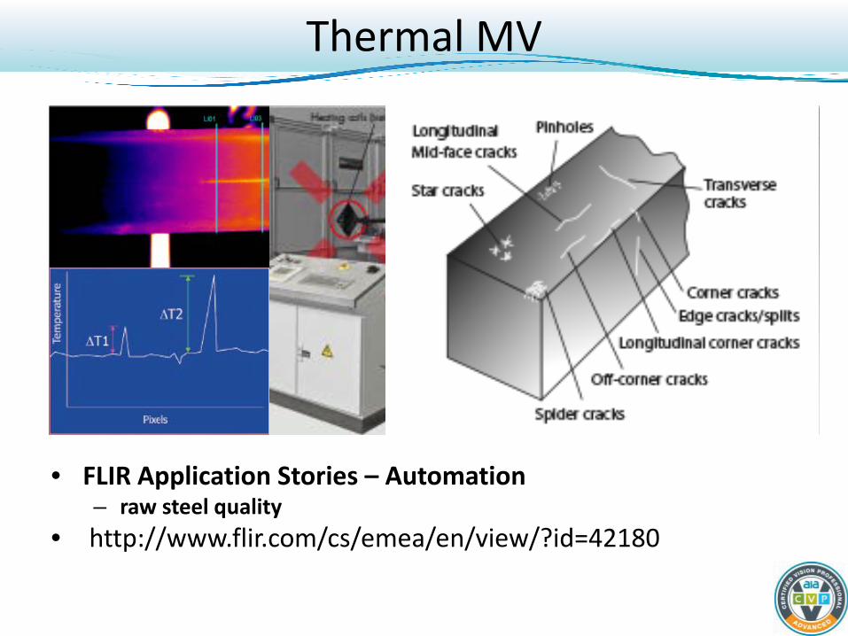
Thermal MV
• FLIR Application Stories – Automation – raw steel quality
• http://www.flir.com/cs/emea/en/view/?id=42180

• 0.1 mm (or 100 μm) infrared to 1.0 mm microwave aka the long-wavelength edge of far-infrared light.
• From 3000 GHz (3×10¹² Hz or 3 THz) to 300 gigahertz (3×10¹¹ Hz or 0.3 THz), aka high-frequency edge of the microwave band.
• The THz band straddles region of wave-like characteristics (microwave) and particle-like characteristics (infrared).
Terahertz

N I R
• NIR, SWIR and Visible images are mostly due to reflected light
• MWIR and LWIR are dominated by thermal emission
• Glass optics and windows only transmit in UV-VIS-NIR-SWIR
Infrared Wavelength Bands

• Reduced Scattering - Longer wavelengths penetrate obscuring layers (haze, fog, smoke) – Small particles (relative to light wavelength) scatter short wavelengths heavily
(Rayleigh scattering model) – Medium particles scatter proportionally to wavelength (Mie scattering model) – Large particles scatter all wavelengths
• For Chemical ID - Molecular vibrations absorb light in unique wavelength bands – SWIR bands easily observed remotely with diffuse reflected light – No sample preparation – Lower detector cooling needs less costly, more robust
• For SWIR MV – Sees contrast where visible cameras do not – illumination is non-interfering with visible cameras
• For Telecom - Fiber communications use SWIR wavelengths
• For Silicon inspection – Silicon and GaAs detectors become transparent and/or emit in SWIR wavelengths when excited
Why Use SWIR Wavelengths
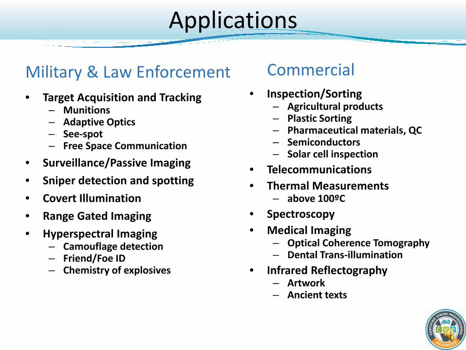
Military & Law Enforcement • Target Acquisition and Tracking
– Munitions – Adaptive Optics – See-spot – Free Space Communication
• Surveillance/Passive Imaging • Sniper detection and spotting • Covert Illumination • Range Gated Imaging • Hyperspectral Imaging
– Camouflage detection – Friend/Foe ID – Chemistry of explosives
Commercial • Inspection/Sorting
– Agricultural products – Plastic Sorting – Pharmaceutical materials, QC – Semiconductors – Solar cell inspection
• Telecommunications • Thermal Measurements
– above 100ºC • Spectroscopy • Medical Imaging
– Optical Coherence Tomography – Dental Trans-illumination
• Infrared Reflectography – Artwork – Ancient texts
Applications

• Imaging - Observing a scene to make an image – Thermal analysis: metal smelting, furnace monitoring, hot glass
processing – Machine Vision Inspection: agriculture, pharmaceutical, semiconductors,
solar cell electroluminescence – Detect or see through coatings
– Surveillance: Imaging through haze – Dentistry: Imaging caries and enamel erosion in teeth
• Spectral - Looking at multiple wavelengths to conduct an analysis – Biomedical: Optical Coherence Tomography, multi-spectral imaging – Telecommunication: Monitor multiple wavelengths simultaneously – Sorting: plastic recycling, agriculture product classification – General spectroscopy: scientific investigation, chemical ID
Two Major Industrial Segments

Imaged in late afternoon in high humidity, 300 mm lens, 1.5 km distant Visible SWIR
Seeing Through Haze – Orlando, Florida

• Haze penetration capability provides overall sharper image • Significantly increases “seeing distance”
Visible
San Francisco Skyline – 3 km
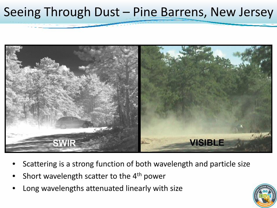
• Scattering is a strong function of both wavelength and particle size • Short wavelength scatter to the 4th power • Long wavelengths attenuated linearly with size
Seeing Through Dust – Pine Barrens, New Jersey

This unique ability of SWIR applies to haze and fog, too!
Cloud Cap Gimbal holds two cameras
Video switches back and forth from Visible to
SWIR
Seeing Through Smoke Forest Fire – Mt. Hood
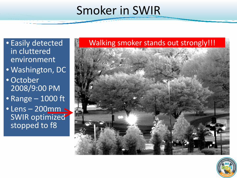
• Easily detected in cluttered environment
• Washington, DC • October
2008/9:00 PM • Range – 1000 ft • Lens – 200mm
SWIR optimized stopped to f8
Walking smoker stands out strongly!!!
Smoker in SWIR
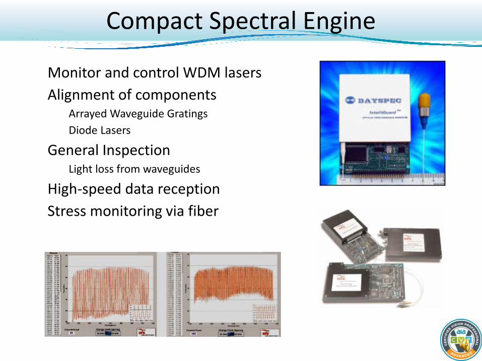
• Monitor and control WDM lasers • Alignment of components
– Arrayed Waveguide Gratings – Diode Lasers
• General Inspection – Light loss from waveguides
• High-speed data reception • Stress monitoring via fiber
Compact Spectral Engine

• Plastic Sorting • Agricultural Sorting • Fruit and Vegetable
Inspection • Seed Sorting
SUI line scan cameras
Industrial Process Monitoring
630
65
230 180 430
1
10
100
1000
10000
100000
10 100 1000
ADC
Cou
nts
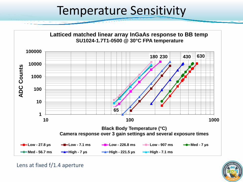
Black Body Temperature (°C) Camera response over 3 gain settings and several exposure times
Latticed matched linear array InGaAs response to BB temp SU1024-1.7T1-0500 @ 30°C FPA temperature
Low - 27.8 µs Low - 7.1 ms Low - 226.8 ms Low - 907 ms Med - 7 µs
Med - 56.7 ms High - 7 µs High - 221.5 µs High - 7.1 ms
Lens at fixed f/1.4 aperture
Temperature Sensitivity

• Lattice matched InGaAs is useful for imaging thermal processes above 100ºC – Too cold for silicon cameras – Glass is opaque at longer wavelengths
• Glass manufacturing • Smelting of metals • Furnace monitoring
Industrial Thermal Imaging

• Bottles placed on conveyor after molding
• SWIR images inside and outside
• Glass stringers difficult to image after cooled
Hot Hollow Glass Mfg

• Some plastics transmit SWIR light but are opaque to visible light
• Water based contents absorb in SWIR • Product in bottle • Product on bottle visible
SWIR
Fill Level
Spills
Inspection Applications

Renoir’s Luncheon of the Boating Party Courtesy of the Phillips Collection, Washington, DC
Imaging through Paint Art Research and Restoration

• The high reflectivity of natural hair makes it appear white
• Note the different materials in costume
SWIR Penetrates Disguises and Makeup
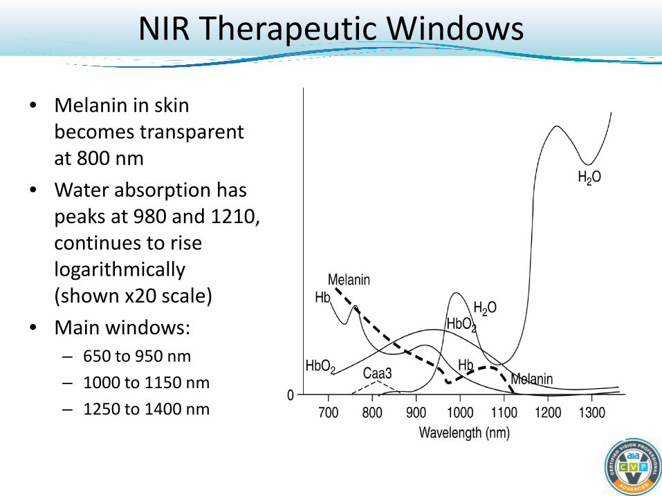
• Melanin in skin becomes transparent at 800 nm
• Water absorption has peaks at 980 and 1210, continues to rise logarithmically (shown x20 scale)
• Main windows: – 650 to 950 nm – 1000 to 1150 nm – 1250 to 1400 nm
NIR Therapeutic Windows
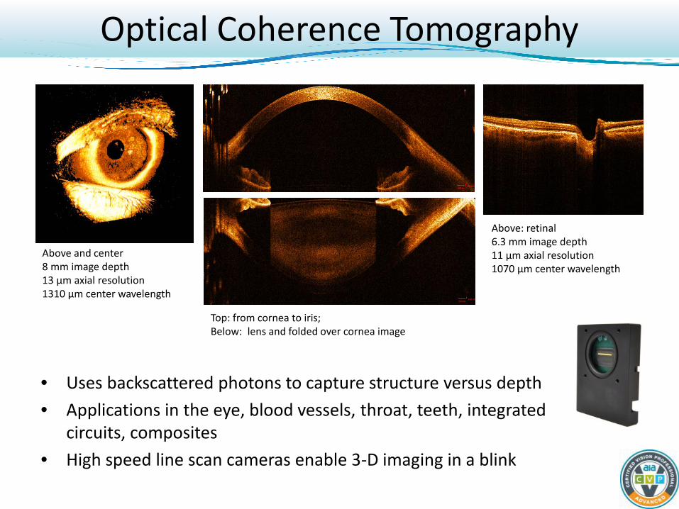
• Uses backscattered photons to capture structure versus depth • Applications in the eye, blood vessels, throat, teeth, integrated
circuits, composites • High speed line scan cameras enable 3-D imaging in a blink
Above and center 8 mm image depth 13 µm axial resolution 1310 µm center wavelength
Above: retinal 6.3 mm image depth 11 µm axial resolution 1070 µm center wavelength
Top: from cornea to iris; Below: lens and folded over cornea image
Optical Coherence Tomography

S. Hariri et. al., submitted to J. Biomed. Opt. (2010)
1060nm UHROCT of the Human Retina
Healthy retina showing nerve fiber bundles
(en-face)
Capillary network in ON
Head (en-face)
Optical Nerve Head showing
arteries & veins (en-face)
Chorio-capillaries network
(deeper image at edges shows larger vessels)
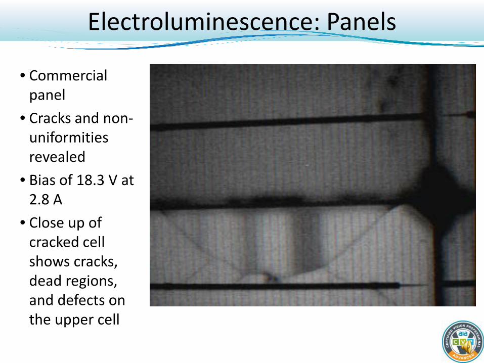
• Commercial panel
• Cracks and non-uniformities revealed
• Bias of 18.3 V at 2.8 A
• Close up of cracked cell shows cracks, dead regions, and defects on the upper cell
Electroluminescence: Panels

1096
1146
1177
0%
10%
20%
30%
40%
50%
60%
70%
80%
90%
0
10
20
30
40
50
60
70
80
90
900 1000 1100 1200 1300 1400 1500 1600 1700
Qua
ntum
Effi
cien
cy
Dig
ital c
ount
s Wavelength (nm)
Solar cell emission spectra
Si emission BI DeepDepl Si QE InGaAs QE
• Imaging spectrograph of 2nd cell on lower row of cells
• Emission at bandgap of silicon
• Spread (width) indicates structure is not pure mono-crystalline
Si Electroluminescence

• Flood illuminated with ~30 W of diffuse laser light at 810 nm • Filtered with 1000 nm long pass filter – 1 for SWIR, 3 for CCD • PL is non-contact; EL requires electrical connections
PL - SWIR 16 ms exposure time PL - Silicon BI CCD – 1 second ET EL w/1.5 V bias – SWIR 16 ms
Photoluminescence Inspection Finished Cell
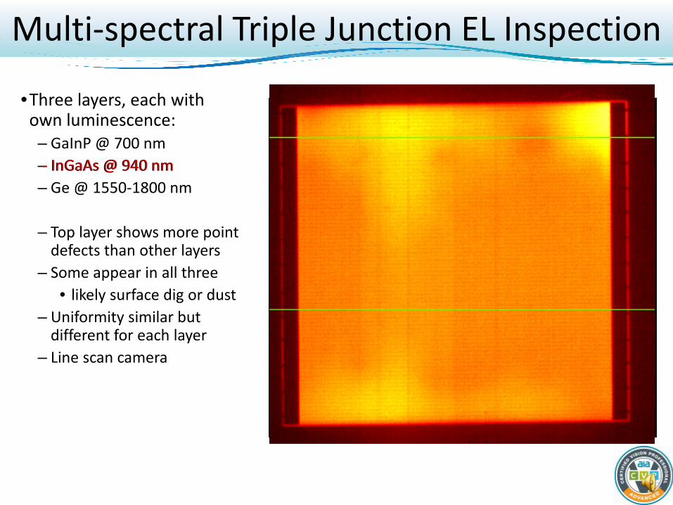
•Three layers, each with own luminescence: – GaInP @ 700 nm – InGaAs @ 940 nm – Ge @ 1550-1800 nm
– Top layer shows more point
defects than other layers – Some appear in all three
• likely surface dig or dust – Uniformity similar but
different for each layer – Line scan camera
- InGaAs @ 940 nm
• ss
Multi-spectral Triple Junction EL Inspection
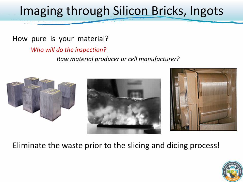
How pure is your material? Who will do the inspection? Raw material producer or cell manufacturer?
Eliminate the waste prior to the slicing and dicing process!
Imaging through Silicon Bricks, Ingots

6”x6”x10” Brick
High Quality Silicon Brick cut from larger ingot and polished
on one face
Maglite flashlight 36” from backside of the block. AF Chart
against backside of block.
Colimated light shining
on target
Rotated polished side
to camera: sharper image
Imaging through Silicon Bricks, Ingots

• The short wave infrared covers the wavelength range from 0.7 to 2.5 microns • InGaAs detectors cover much of this range, enabling small cameras with low
power and weight because of high sensitivity at room temperature for SUI process
• Imaging in the SWIR is different from visible imaging due to differences in optical scattering, and spectral absorbance
• Imaging in the MWIR and LWIR is different from SWIR in that the thermal emission of objects dominate the scene, rather than reflection of ambient light
• SWIR machine vision inspection applications help to: – see ‘invisible’ transparent coatings, – see through opaque coatings, – see through silicon, – sort materials, agricultural products, and pharmaceutical chemicals – Align and monitor the telecommunications network
SWIR Summary
Douglas Malchow Manager, Industrial Business Development
Sensors Unlimited, Inc. Princeton, New Jersey USA Phone: (609) 333-8249 Email: [email protected] www.sensorsinc.com
Contact Information


