
Semiconductor Based Temperature Sensors
- Motor Protection Thermistors (PTC)- Thermistors (NTC)- Silicon Sensors (KTY)
www.ephy-mess.dewww.ephy-mess.de

Contents 1. Notes to the use of the catalogue ....................................................................................................... 2
2. Introduction .......................................................................................................................................... 2
3. Motor Protection Thermistors (PTC) ................................................................................................... 3
3.1 General ................................................................................................................................................ 3
3.2 Classical Motor Protection Thermistor Type (EPTC / DPTC-SH-xxx) ................................................ 4
4. Thermistor (NTC) ................................................................................................................................ 6
4.1 General ................................................................................................................................................ 6
4.2 Thermistors for Temperature Control Type (K227) ............................................................................. 6
5 Silicon Sensors .................................................................................................................................... 9
5.1 General ................................................................................................................................................ 9
5.2 Sensor Production Series 83-1xx and 84-1xx ................................................................................... 10
5.2.1 KTY-Sensor Production Series 83-1xx ............................................................................................. 10
5.2.2 KTY Sensor Production Series 84-1xx.............................................................................................. 13
6. Confectioning variations .................................................................................................................... 16
6.1 Confectioning variations with Ex certification according to ATEX ..................................................... 16
6.2 Confectioned Shrinkage Tube Insulated Sensors Type (XXX-XSH) ................................................ 17
6.3 Confectioned Sensors in Ceramic Collet Type (XXX-KH) ................................................................ 18
6.4 Confectioned Sensors in Metal Collet Type (XXX-MH) .................................................................... 19
6.5 Thermometer for Screwing In Type (XXX-SGH) ............................................................................... 20
6.6 Slot Resistance Thermometer Type (ZS / AK / E-NTS-ZS / KTY-ZS) .............................................. 22
7. Switching Devices for PTC Thermistors and KTY Sensors .............................................................. 24
7.1 General .............................................................................................................................................. 24
7.2 Operating and Application Fields of PTC Thermistor Switching Devices ......................................... 24
7.3 PTC Thermistor Release Devices ..................................................................................................... 25
7.3.1 Release Device Type (INT69) ........................................................................................................... 25
7.3.2 Release Device Type (TÜS100) ....................................................................................................... 27
7.3.3 PTC Release Device with ATEX Approval Type MS(R) ................................................................... 29
7.3.4 KTY Release Device Type (KTY 04.01-R) ........................................................................................ 30

2 EPHY-MESS Semiconductors REV201509071
1 Notes to the use of the Catalogue
Products included in this catalogue represent a general overview of the principally deliverable types of
construction and confectioning variations of PTC-, NTC- und KTY- Sensors of EPHY-MESS. At first the
individual basic types of construction of the sensors, as well as the technical benchmark figures are
presented. An overview of the default deliverable possibilities of confectioning follows. Finally some release
devices for the different types of sensors are discussed. The different variations and modifications for one
product are separated by the sign "│". Please note that the variations cannot be combined always freely,
because, for example, a small collet diameter only allows a specific hose pipe or a special sensor. The
confectioning variations shown in the catalogue are standard types of construction. However, any customer
specific solutions are practicable. The specification sheets are kept general and normally specify only the
benchmark figures. Due to the countless number of possibilities which could result, it is unfortunately not
possible to display all variations. In the case of special requirements or desires, please contact our sales
department. We would gladly develop with you a temperature sensor according your special requirements. A
confectioning of sensors, as set by you, is also possible.
2 Introduction
For the thermal control of electrical machines motor protection (PTC, NTC) thermistors, as well as (NTC)
silicon sensors (KTY of the production series 83-1xx and 84-1xx), have stood the test at best. Motor
protection PTC thermistors qualify very good for control of a limit temperature. By use of these PTC
thermistors and a suitable switching device a reliable overheating protection system can be realised. By
means of silicon sensors and NTC in many cases a well-priced temperature measurement can be realised.
All sensors are mainly confectioned by EPHY-MESS for the placement inside the winding or slot of electrical
machines. But they are also suitable for other tasks of temperature measurement and control.

REV201509071 EPHY-MESS Semiconductors 3
3 Motor Protection Thermistors (PTC)
3.1 General
A Positive Temperature Coefficient thermistor (PTC) is a semiconductor of endowed, polycrystalline barium
titanate ceramic, whose electrical resistance rapidly increases when a certain temperature is exceeded. PTC
thermistors deliverable by EPHY-MESS are mainly motor protection thermistors according to DIN 44081 –
82, which are set in the winding of electrical motors, generators and transformers. The typical resistance /
temperature characteristic of motor protection thermistors is displayed in the following diagram.
R(PTC) = f (TPTC)
RN PTC thermistor resistance at TN
TN Rated temperature (25°C)
Rmin Minimum resistance
TRmin Temperature at Rmin (beginning of the positive )
RRef Reference resistance at TRef
TRef Reference temperature (beginning of the steep resistance
increase)
RPTC Arbitrary resistance in the steep zone
TPTC to RPTC belonging temperature
TNAT Nominal response temperature for motor protection PTC
thermistors defined instead of the reference temperature in the
steep zone
Fig. 1: Characteristic response curve flow of motor protection PTC thermistors RPTC = f (TPTC)
At combination of a motor protection PTC thermistor with a switching device one receives an effective, well-
priced and quickly reacting solution for the protection of electrical machines from overheating.
As visible in fig. 1, the resistance value of the PTC thermistor increases steeply after reaching of its
reference temperature. For the classification of the sensor one fixes a point in the steep zone of the
response curve, the so called nominal response temperature (NAT). It signifies the temperature value, at
which the downstream connected release device reacts inside the tolerance range. At the selection of the
used PTC, its NAT incl. tolerance has to be chosen so, that it corresponds to the maximum acceptable
operation temperature of the motor. The PTC’s are also to be connected in series with different NAT inside a
measurement circuit. Thereby different ranges of temperature of a machine can be controlled with only one
measurement circuit. As soon as at one PTC the by its NAT defined maximum temperature is exceeded, the
connected downstream switching device switches the machine off. Furthermore the usage of 2 different NAT
is possible, if for example, one wants to realise at a single motor a combination of forewarn and shutoff.
However in this case two measurement circuits are necessary.
[ ]
[°C]TPTCTN TRmin TRef
RRef
Rmin
RPTC
T
Lg R
RN

4 EPHY-MESS Semiconductors REV201509071
3.2 Classical Motor Protection Thermistor Type (EPTC / DPTC-SH-xxx)
Fig. 2: DPTC-SH-155 standard: KL=500/180/180/500 mm
Designation EPTC / DPTC-SH-xxx EPTC = single PTC thermistor DPTC = triplet PTC thermistor SH = shrinkage tube coat xxx = (NAT) nominal response temperature [°C]
Construction EPTC-SH-xxx
PTC thermistor pill according to DIN 44081 varnish and shrinkage tube insulated with fix connected single strands
DPTC-SH-xxx
3 PTC thermistor pills according to DIN 44082 varnish and shrinkage tube insulated with fix connected single strands boarded in series
UL-approval UL 1434 (UL file-Nummer E69802) optional incl. NAT 180°C Measuring element EPTC type single PTC thermistor material Bariumtitanat (BaTiO3) connection 2-wire circuit
resistance value R<100 at metering voltage ≤ 2,5V tolerance ±5K acc. DIN 44081 (up to/ incl. NAT 160°C) ±7K acc. DIN 44081 (starting at NAT 170°C) Measuring element DPTC type triple PTC thermistor material Bariumtitanat (BaTiO3) connection 2- wire circuit
resistance value R<300 at metering voltage ≤ 2,5V (bis incl. NAT 180°C)
R<350 at metering voltage ≤ 2,5V (from NAT 190°C) tolerance ±5K acc. DIN 44082 (up to/ incl. NAT 160°C) ±7K acc. DIN 44082 (from NAT 170°C)
IECEx: Ex eb IIC, Ex ta IIIC, Ex ia IIC Gb, Ex ia IIIC Gb ATEX: II 2G Ex e IIC Gb, II 2D Ex ta IIIC Da, II 2G Ex ia IIC Gb, II 2D Ex ia IIIC Db TR: Ex e II U, Ex tb IIIC Db U, Ex ia IIC U, Ex ia IIIC Db U

REV201509071 EPHY-MESS Semiconductors 5
Electric values EPTC
nominal switching temperature NAT °C (see above) max. operating voltage 30VDC valid in the range from 0°C … +40°C max. measuring voltage 7,5VDC in the range from -25°C up to TNAT +23K dielectric strength 2,5 kV / AC 50 Hz / 1 min.
Electric values DPTC nominal switching temperature NAT °C (see above) max. operating voltage 30 V DC valid in the range from 0°C … +40°C max. measuring voltage 7,5 V DC in the range from -25°C up to TNAT +23K dielectric strength 2,5 kV / AC 50 Hz / 1 min.
Temparature range operating temperature -25°C … +200°C; above +200°C a possible self-heating caused by the measuring voltage has to be considered.
Pill size (insulated) Old, former standard pill ø<4mm │ Up-to-date mini pill ø < 3mm
Pill insulation T < 160°C => Kynar®
shrinkage tube
T 160°C => PTFE shrinkage tube
Nominal response temperature 60°C ... +190°C
Colour codes
TNAT [°C] Colour code
60 WH / GY
70 WH / BN
80 WH / WH
90 GN / GN
100 RD / RD
110 BN / BN
120 GY / GY
130 BU / BU
140 WH / BU
145 WH / BK
150 BK / BK
155 BU / BK
160 BU / RD
170 WH / GN
180 WH / RD
190 BK / GY
Tab. 1: Colour code of motor protection PTC thermistors according to DIN 40080
Connection line Single strands AWG 26/7
Insulation PTFE
Standard cable length1 EPTC 500mm │ 2000mm
DPTC 500/180/180/500mm │ 2000/300/300/2000mm
1 Other cable length on request

6 EPHY-MESS Semiconductors REV201509071
Colour code Outside connection according to Tab. 1
Inside connection for DPTC = YE (yellow)
Confectioning variations ESH/DSH │ SGH │ KH │ AK/ZS │ MH
4 Thermistor (NTC)
4.1 General
A NTC thermistor is according to DIN 44070 resp. IEC 60593 a temperature dependant semiconductor
resistor whose value of resistance decreases with growing temperature. The Negative Temperature
Coeffizient (NTC) lies at approx. -2... -6%/K and is therewith approx. ten times bigger as for metals.
Therefore thermistors are well suitable for the measurement of temperatures. They consist of manganese,
iron, cobalt, nickel, copper and zinc oxide; those are admixed with other oxides for chemical stabilisation.
These are prepared to a powdery compound and after addition of a plastic binding agent sintered at
temperatures of approx. 1000 - 1400°C. Afterwards the polycrystalline semiconductors are pinned and by
means of special ageing methods aged for the stabilisation of the resistant values aged.
The change of the resistance in operation can be caused by a change in the temperature of the environment,
as well as by self-heating as a result of electrical loading. While using PTC thermistors the response
temperature of the protection equipment is defined by the NAT of the PTC, one can adjust the switching
point of a NTC at the corresponding switching device.
4.2 Thermistors for Temperature Control Type (K227)
Fig. 3: Motor protection PTC thermistor type K227, 1,8k
Specification NTC-SH, type K227 B57227 K333A, 1,8k
Special construction 10 k, technical dates on request
ATTENTION: all here mentioned dates refer to the type 1.8 k
Construction Thermistor disk with Kynar shrinkage tube insulation and fix connected single strands
Pill dimensions (insulated) ømax= 5 mm x 14 mm
Application For the thermal control of electrical machines and the temperature measurement inside electrical motors and transformers
Temperature range -55...155°C
Max. power 200mW at T=25°C
REV201509071 EPHY-MESS Semiconductors 7
Resistance tolerance R/RN = ±10%
Nominal resistance (RN) 1.8 k │ 10 k special construction
Nominal temperature 100°C
Resistance R25°C 32.762 k
Heat conductance value 5 mW/K (in static air)
Therm. cooling period constant 30 s (in static air)
Heat capacity 150 mJ/K
Insulation resistance (U=100V) >100 MOhm
Dielectric strength 2.5 kV / AC 50Hz / 1min.
B-value (B25/B100) 4300 K
B-value tolerance ±1.5%
Pill insulation Kynar®
shrinkage tube
Connection line PTFE single strands Cable section AWG26
Colour code Red / Grey
Cable length (standard) 380mm │ 2000mm

8 EPHY-MESS Semiconductors REV201509071
Characteristic curve
1,E+02
1,E+03
1,E+04
1,E+05
1,E+06
1,E+07
-60 -40 -20 0 20 40 60 80 100 120 140 160 180
T [°C]
R [Ohm]
Fig. 4: Characteristic curve NTC K227, 1,8kOhm
Confectioning variations ESH/DSH │ SGH │ KH │ AK/ZS │ MH

REV201509071 EPHY-MESS Semiconductors 9
5 Silicon Sensors
5.1 General
Silicon sensors of the KTY production series are like diodes built semiconductors. Their operation
temperature range extends from –55°....+ 175°C (KTY 83 series), resp. from 40°...+300°C (KTY84 series),
what is sufficient for the most industrial measuring purposes. They have, just as PTC thermistors, a positive
temperature coefficient but in contrary to them they show an approximate linear characteristic line. Their
resistance response is comparable with this of a precision resistor with a big temperature coefficient. The
range of application is the measuring of temperatures and control of limit values. The range of tolerance at
reference temperature lies according to the construction between 3 and 5%, what is compared with a Pt100
relatively inexact. But for many applications, as e.g. motor protection, this is completely sufficient, because in
this case the sensors operate mostly relatively close to their nominal temperature (for KTY84-1xx) and at this
applications a degree more or less is not important. For this reason, in industry they are a very common and
a low priced alternative for the classical Pt100. By EPHY-MESS confectioned sensors base on the KTY
production series 83-1xx and 84-1xx. On customers request, other KTY types are available.
10 EPHY-MESS Semiconductors REV201509071
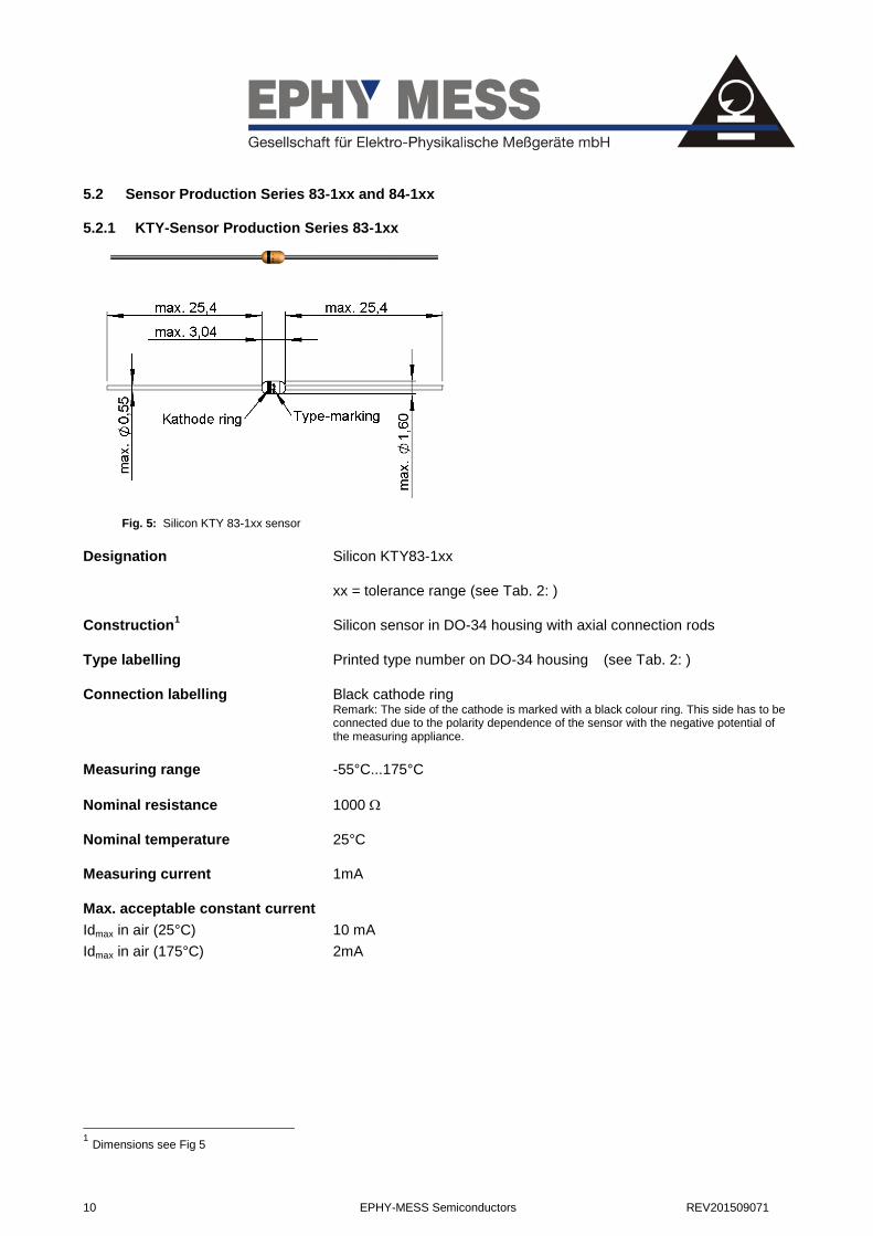
5.2 Sensor Production Series 83-1xx and 84-1xx 5.2.1 KTY-Sensor Production Series 83-1xx
Fig. 5: Silicon KTY 83-1xx sensor
Designation Silicon KTY83-1xx
xx = tolerance range (see Tab. 2: )
Construction1 Silicon sensor in DO-34 housing with axial connection rods
Type labelling Printed type number on DO-34 housing (see Tab. 2: )
Connection labelling Black cathode ring Remark: The side of the cathode is marked with a black colour ring. This side has to be connected due to the polarity dependence of the sensor with the negative potential of the measuring appliance.
Measuring range -55°C...175°C
Nominal resistance 1000
Nominal temperature 25°C
Measuring current 1mA
Max. acceptable constant current
Idmax in air (25°C) 10 mA
Idmax in air (175°C) 2mA
1 Dimensions see Fig 5
REV201509071 EPHY-MESS Semiconductors 11
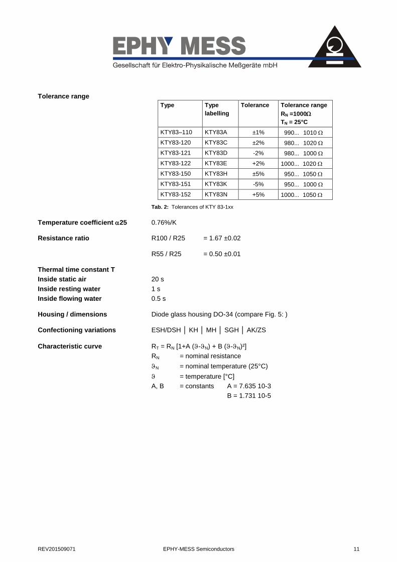
Tolerance range
Type Type
labelling
Tolerance Tolerance range
RN =1000
TN = 25°C
KTY83–110 KTY83A ±1% 990... 1010
KTY83-120 KTY83C ±2% 980... 1020
KTY83-121 KTY83D -2% 980... 1000
KTY83-122 KTY83E +2% 1000... 1020
KTY83-150 KTY83H ±5% 950... 1050
KTY83-151 KTY83K -5% 950... 1000
KTY83-152 KTY83N +5% 1000... 1050
Tab. 2: Tolerances of KTY 83-1xx
Temperature coefficient 25 0.76%/K
Resistance ratio R100 / R25 = 1.67 ±0.02
R55 / R25 = 0.50 ±0.01
Thermal time constant T
Inside static air 20 s
Inside resting water 1 s
Inside flowing water 0.5 s
Housing / dimensions Diode glass housing DO-34 (compare Fig. 5: )
Confectioning variations ESH/DSH │ KH │ MH │ SGH │ AK/ZS
Characteristic curve RT = RN [1+A (-N) + B (-N)²]
RN = nominal resistance
N = nominal temperature (25°C)
= temperature [°C]
A, B = constants A = 7.635 10-3
B = 1.731 10-5
12 EPHY-MESS Semiconductors REV201509071
0
4
8
12
-50 0 50 100 150 200T [°C]
Ic max
[mA]
0,4
1,2
2,0
2,8
-100 0 100 200T[°C]
R
[k]
-10
0
10
20
30
40
0 1 2Ic [mA]
R []
8
4
0
-4
-8
-50 0 50 100 150
T[°C]
T[K]
KTY83-110 -121 -122
KTY83-151 -152 -120
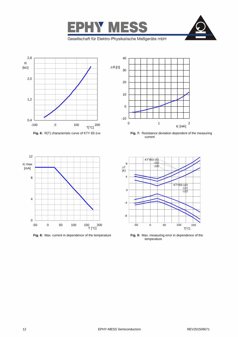
Fig. 6: R(T) characteristic curve of KTY 83-1xx
Fig. 7: Resistance deviation dependent of the measuring current
Fig. 8: Max. current in dependence of the temperature
Fig. 9: Max. measuring error in dependence of the temperature

REV201509071 EPHY-MESS Semiconductors 13
5.2.2 KTY Sensor Production Series 84-1xx
Fig. 10: Silicon KTY production series 84-1xx
Designation Silicon KTY84-1xx
xx = tolerance range (see Tab. 3: )
Construction Silicon sensor in DO-34 housing with axial connection rods
Type labelling Printed type number on DO-34 housing (see Tab. 3: )
Connection labelling Black cathode ring Remark: The side of the cathode is marked with a black colour ring. This side has to be connected due to the polarity dependence of the sensor with the negative potential of the measuring appliance.
Colour code1 (+) = yellow (-) = green
Measuring range -40°C ... +300°C
Nominal resistance 1000
Nominal temperature 100°C
Measuring current 2 mA
Max. acceptable constant current
IDmax inside air (25°C) 10 mA
IDmax inside air (300°C) 2 mA
1 At confectioning variations of Ephy-Mess

14 EPHY-MESS Semiconductors REV201509071
Tolerance range
Tab. 3: Tolerances of KTY 84-1xx
Temperature coefficient 25 = 0.61%/K
Resistance ratio R250/R100 = 2.166±0.055
R25/R100 = 0.603 ±0.08
Thermal time constant T
Inside static air 20 s
Inside resting water 1 s
Inside flowing water 0.5 s
Housing / dimensions Diode glass housing DO-34 (compare Fig. 10: )
Confectioning variations ESH/DSH │ KH │ MH │ SGH │ AK/ZS
Characteristic curve RT = RN [1+A (-N) + B (-N)²]
RN = nominal resistance
N = nominal temperature (100°C)
= temperature [°C]
A, B = constants A = 6.229 10-3
B = 1.159 10-5
Type Type labelling
Tolerance Tolerance range
RNenn = 1000
TNenn = 100°C
KTY84-130 KTY84L ± 3% 970....1030
KTY84-150 KTY84M ±5% 950...1050
KTY84-151 KTY84O -5% 950…1000
KTY84-152 KTY84P +5% 1000…1050
REV201509071 EPHY-MESS Semiconductors 15
0,0
1,0
2,0
3,0
-100 0 100 200 300
T [°C]
R
[k]
0
4
8
12
-100 0 100 200 300
I cont
[mA]
T[°C]
-30
-20
-10
0
10
20
30
-100 0 100 200 300
Tamb(°C)
T(K)
KTY84-150
KTY84-150
KTY84-130 -151 -152
-10
0
10
20
30
40
1 2 3
I const
[mA]
R
[]
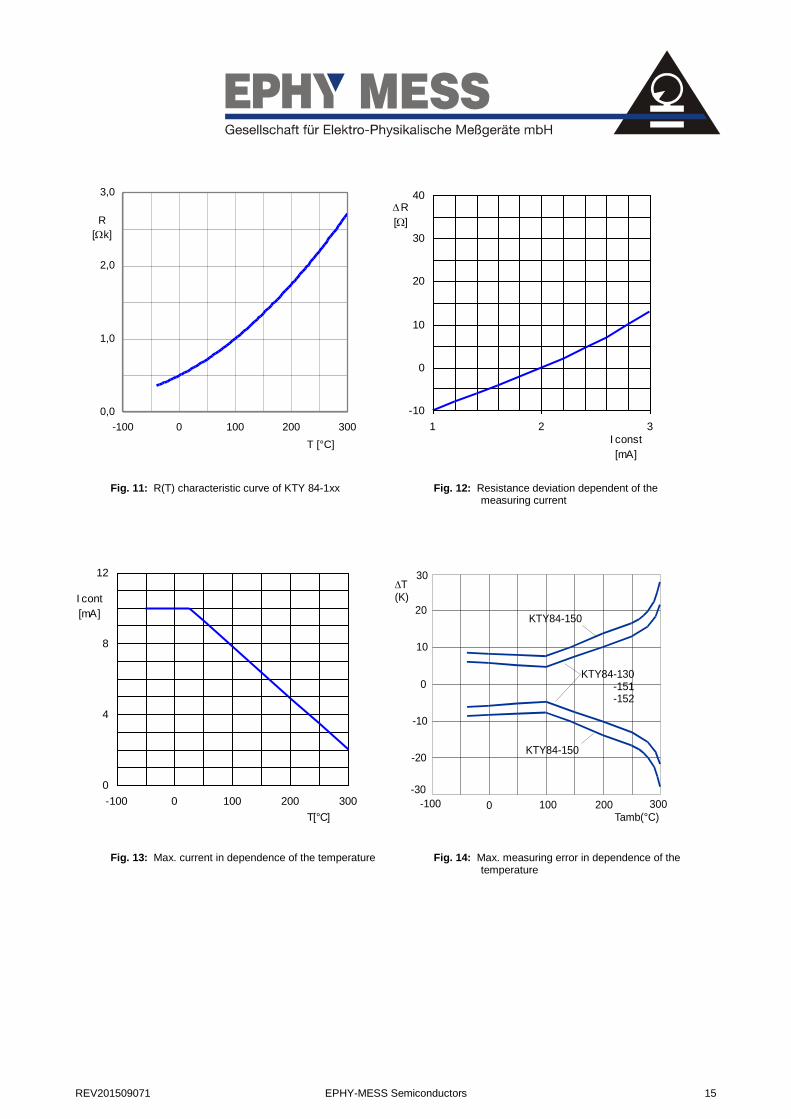
Fig. 11: R(T) characteristic curve of KTY 84-1xx
Fig. 12: Resistance deviation dependent of the measuring current
Fig. 13: Max. current in dependence of the temperature
Fig. 14: Max. measuring error in dependence of the temperature

16 EPHY-MESS Semiconductors REV201509071
6 Confectioning variations
The following table gives a general view over the different confectioning variations of the single basic sensors.
Designation Construction PTC DPTC NTC KTY
XXX-ESH XXX-Sensor with a single layer of shrinkable tube and a fix connected supply line
XXX XXX XXX XXX
XXX-DSH XXX-Sensor with a double layer of shrinkable tube and a fix connected supply line
XXX XXX XXX XXX
XXX-MH XXX-Sensor built into a metall sleeve with fix connected supply line
XXX XXX XXX
XXX-KH XXX-Sensor sealed into a ceramic sleeve with fix connected supply line
XXX XXX XXX XXX
XXX-SGH XXX-Sensor built into a screw housing with fix connected supply line
XXX XXX XXX
XXX-AK XXX-Sensor built in a HGW intake body (AK). Closed with cover disk and additional insulated with PTFE shrinkage tube. Fix connected supply line.
XXX XXX XXX
XXX-ZS XXX-Sensor buitd into a ZS housing XXX XXX XXX
Tab. 4: Confectioning variations of basic sensors
6.1 Confectioning variations with Ex certification according to ATEX
Typ Bauform Sensor IEC Ex ATEX TR
PR-SPA-EX-WKF
XXX - ESH XXX - DSH XXX – MH XXX - KH XXX - SGH
PTC*│KTY83/84 Ex eb IIC
Ex ta IIIC Ex ia IIC Gb Ex ia IIIC Gb
II 2G Ex e IIC Gb II 2D Ex ta IIIC Da II 2G Ex ia IIC Gb II 2D Ex ia IIIC Db
Ex e II U Ex tb IIIC Db U Ex ia IIC U Ex ia IIIC Db U
PR-SPA-EX-NWT XXX – AK XXX - ZS
PTC*| KTY83/84
*acc. DIN 44081-82
Tab. 5: Confectioning variations with Ex certification according to IECEx, ATEX and TR certification
REV201509071 EPHY-MESS Semiconductors 17
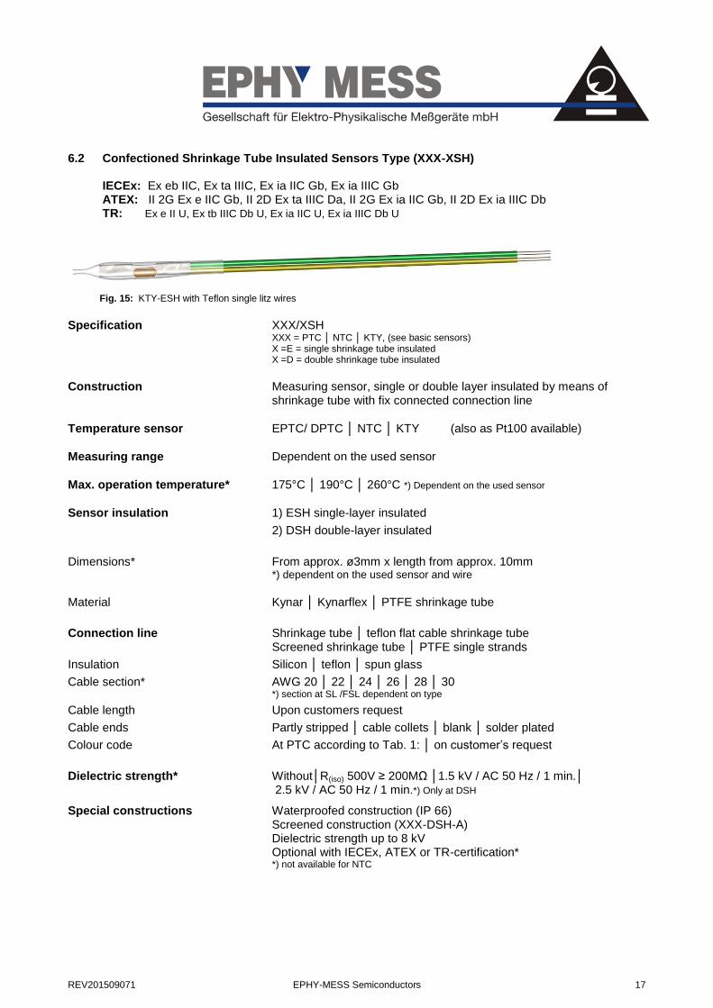
6.2 Confectioned Shrinkage Tube Insulated Sensors Type (XXX-XSH)
Fig. 15: KTY-ESH with Teflon single litz wires
Specification XXX/XSH XXX = PTC │ NTC │ KTY, (see basic sensors) X =E = single shrinkage tube insulated X =D = double shrinkage tube insulated
Construction Measuring sensor, single or double layer insulated by means of shrinkage tube with fix connected connection line
Temperature sensor EPTC/ DPTC │ NTC │ KTY (also as Pt100 available)
Measuring range Dependent on the used sensor
Max. operation temperature* 175°C │ 190°C │ 260°C *) Dependent on the used sensor
Sensor insulation 1) ESH single-layer insulated
2) DSH double-layer insulated
Dimensions* From approx. ø3mm x length from approx. 10mm *) dependent on the used sensor and wire
Material Kynar │ Kynarflex │ PTFE shrinkage tube
Connection line Shrinkage tube │ teflon flat cable shrinkage tube Screened shrinkage tube │ PTFE single strands
Insulation Silicon │ teflon │ spun glass
Cable section* AWG 20 │ 22 │ 24 │ 26 │ 28 │ 30 *) section at SL /FSL dependent on type
Cable length Upon customers request
Cable ends Partly stripped │ cable collets │ blank │ solder plated
Colour code At PTC according to Tab. 1: │ on customer’s request
Dielectric strength* Without│R(iso) 500V ≥ 200MΩ │1.5 kV / AC 50 Hz / 1 min.│ 2.5 kV / AC 50 Hz / 1 min.*) Only at DSH
Special constructions Waterproofed construction (IP 66) Screened construction (XXX-DSH-A) Dielectric strength up to 8 kV Optional with IECEx, ATEX or TR-certification* *) not available for NTC
IECEx: Ex eb IIC, Ex ta IIIC, Ex ia IIC Gb, Ex ia IIIC Gb ATEX: II 2G Ex e IIC Gb, II 2D Ex ta IIIC Da, II 2G Ex ia IIC Gb, II 2D Ex ia IIIC Db TR: Ex e II U, Ex tb IIIC Db U, Ex ia IIC U, Ex ia IIIC Db U
18 EPHY-MESS Semiconductors REV201509071
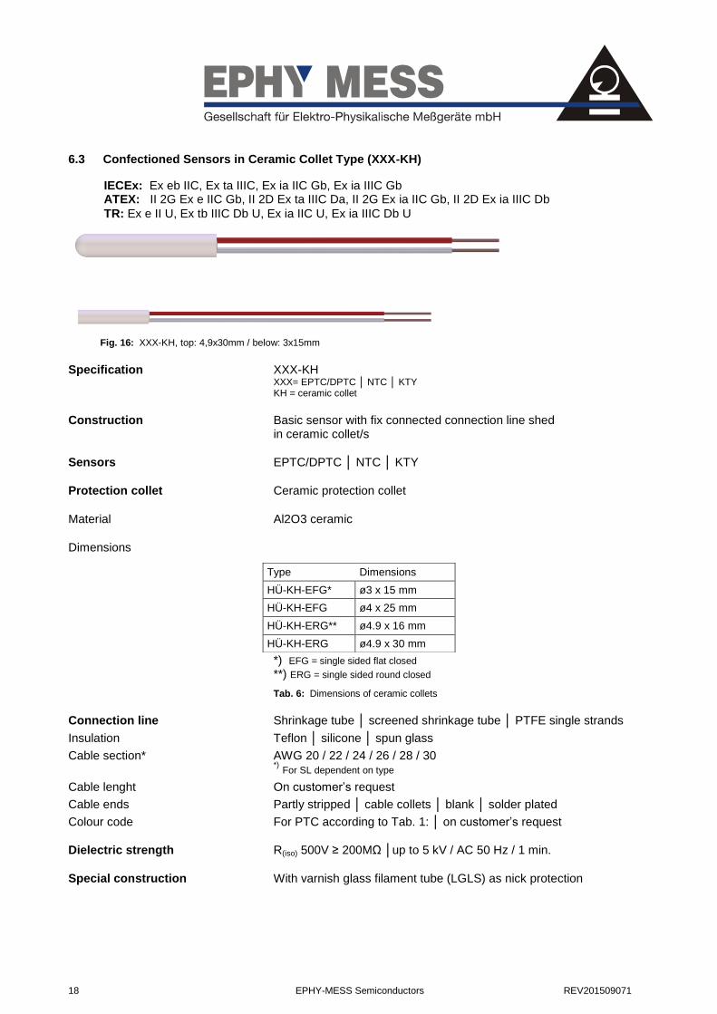
6.3 Confectioned Sensors in Ceramic Collet Type (XXX-KH)
Fig. 16: XXX-KH, top: 4,9x30mm / below: 3x15mm
Specification XXX-KH XXX= EPTC/DPTC │ NTC │ KTY KH = ceramic collet
Construction Basic sensor with fix connected connection line shed in ceramic collet/s
Sensors EPTC/DPTC │ NTC │ KTY
Protection collet Ceramic protection collet
Material Al2O3 ceramic
Dimensions
*) EFG = single sided flat closed **) ERG = single sided round closed
Tab. 6: Dimensions of ceramic collets
Connection line Shrinkage tube │ screened shrinkage tube │ PTFE single strands
Insulation Teflon │ silicone │ spun glass
Cable section* AWG 20 / 22 / 24 / 26 / 28 / 30
*) For SL dependent on type
Cable lenght On customer’s request
Cable ends Partly stripped │ cable collets │ blank │ solder plated
Colour code For PTC according to Tab. 1: │ on customer’s request
Dielectric strength R(iso) 500V ≥ 200MΩ │up to 5 kV / AC 50 Hz / 1 min.
Special construction With varnish glass filament tube (LGLS) as nick protection
Type Dimensions
HÜ-KH-EFG* ø3 x 15 mm
HÜ-KH-EFG ø4 x 25 mm
HÜ-KH-ERG** ø4.9 x 16 mm
HÜ-KH-ERG ø4.9 x 30 mm
IECEx: Ex eb IIC, Ex ta IIIC, Ex ia IIC Gb, Ex ia IIIC Gb ATEX: II 2G Ex e IIC Gb, II 2D Ex ta IIIC Da, II 2G Ex ia IIC Gb, II 2D Ex ia IIIC Db
TR: Ex e II U, Ex tb IIIC Db U, Ex ia IIC U, Ex ia IIIC Db U
REV201509071 EPHY-MESS Semiconductors 19
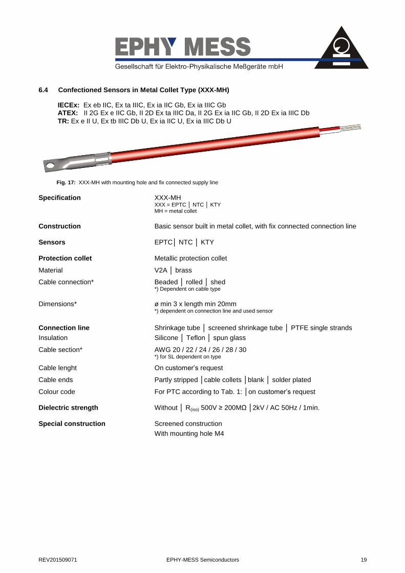
6.4 Confectioned Sensors in Metal Collet Type (XXX-MH)
Fig. 17: XXX-MH with mounting hole and fix connected supply line
Specification XXX-MH XXX = EPTC │ NTC │ KTY MH = metal collet
Construction Basic sensor built in metal collet, with fix connected connection line
Sensors EPTC│ NTC │ KTY
Protection collet Metallic protection collet
Material V2A │ brass
Cable connection* Beaded │ rolled │ shed *) Dependent on cable type
Dimensions* ø min 3 x length min 20mm *) dependent on connection line and used sensor
Connection line Shrinkage tube │ screened shrinkage tube │ PTFE single strands
Insulation Silicone │ Teflon │ spun glass
Cable section* AWG 20 / 22 / 24 / 26 / 28 / 30 *) for SL dependent on type
Cable lenght On customer’s request
Cable ends Partly stripped │cable collets │blank │ solder plated
Colour code For PTC according to Tab. 1: │on customer’s request
Dielectric strength Without │ R(iso) 500V ≥ 200MΩ │2kV / AC 50Hz / 1min.
Special construction Screened construction
With mounting hole M4
IECEx: Ex eb IIC, Ex ta IIIC, Ex ia IIC Gb, Ex ia IIIC Gb ATEX: II 2G Ex e IIC Gb, II 2D Ex ta IIIC Da, II 2G Ex ia IIC Gb, II 2D Ex ia IIIC Db
TR: Ex e II U, Ex tb IIIC Db U, Ex ia IIC U, Ex ia IIIC Db U
20 EPHY-MESS Semiconductors REV201509071
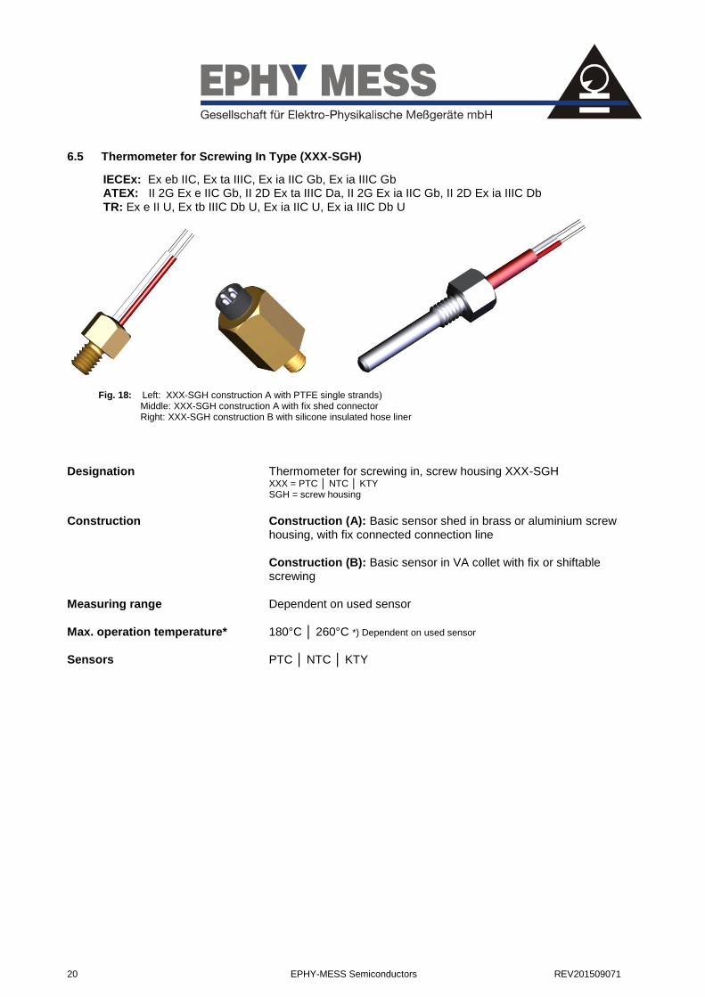
6.5 Thermometer for Screwing In Type (XXX-SGH)
Fig. 18: Left: XXX-SGH construction A with PTFE single strands) Middle: XXX-SGH construction A with fix shed connector Right: XXX-SGH construction B with silicone insulated hose liner
Designation Thermometer for screwing in, screw housing XXX-SGH XXX = PTC │ NTC │ KTY SGH = screw housing
Construction Construction (A): Basic sensor shed in brass or aluminium screw housing, with fix connected connection line
Construction (B): Basic sensor in VA collet with fix or shiftable screwing
Measuring range Dependent on used sensor
Max. operation temperature* 180°C │ 260°C *) Dependent on used sensor
Sensors PTC │ NTC │ KTY
IECEx: Ex eb IIC, Ex ta IIIC, Ex ia IIC Gb, Ex ia IIIC Gb ATEX: II 2G Ex e IIC Gb, II 2D Ex ta IIIC Da, II 2G Ex ia IIC Gb, II 2D Ex ia IIIC Db
TR: Ex e II U, Ex tb IIIC Db U, Ex ia IIC U, Ex ia IIIC Db U

REV201509071 EPHY-MESS Semiconductors 21
Screw housing construction A
Material Thread x mounting length1 SW x height
Brass M4 x 7,5mm SW 7x10mm
Brass M4 x 6mm SW 7x10mm
Brass M5 x 7,5mm SW8x10mm
Brass M6 x 7,5mm SW10x10mm
Brass M6 x 7,5mm SW 8x15mm
Brass M8 x 8mm SW19x24mm2
Brass M8 x 7,5mm SW13x10mm
Aluminium M4 x 6mm SW8x8mm
Aluminium M5 x 6mm SW8x12mm
Tab. 7: Dimensions of standard screw housings
Screwings construction B
Tab. 8: Collets ø and screwings
Connection line Shrinkage tube │ PTFE single strands
Insulation Silicone │ Teflon │ spun glass
Cable length On customer’s request
Cable ends Partly stripped │ cable collets │ blank │ solder plated
Colour code For PTC according to Tab. 1: │ on customer’s request
Dielectric strength Without │ R(iso) 500V ≥ 200MΩ│2kV / AC / 50Hz 1min.
1 For all diamaters ≥ 6mm, the sensor is placed inside the screw base for a better thermal linking
2 with shed connector (4-pole) see 0
Ø-VA collet [mm] mounting length [mm] VA-VSB
4mm
5mm
6mm (standard)
8mm
from 20 M10x1
G1/4“
G3/8“
G1/2“

22 EPHY-MESS Semiconductors REV201509071
6.6 Slot Resistance Thermometer Type (ZS; AK; E-NTS-ZS; KTY-ZS)
Fig. 19: Above: XXX-ZS with flat cable shrinkage tube Below: XXX-AK with PTFE single strands
Designation XXX-ZS slot resistance thermometer
XXX-AK slot resistance thermometer
(E-NTS-ZS) Ex e version (only PTC)
(KTY-ZS) Ex e version (only KTY) ZS = intermediate slide AK = intake body XXX = PTC │ NTC │ KTY
Construction (ZS) Basic sensor with fix connected connection line, fixed by means of bridge and directly shed in epoxy resin intermediate slide housing
(AK) Basic sensor built in and shed in HGW intake body of silicon. Closed with cover disk and additional insulated with PTFE shrinkage tube. Fix connected connection line.
Measuring range Dependent on used sensor
Max. operation temperature1 180°C │ 200°C
Sensors PTC │ NTC │ KTY (also as Pt100 available)
Intake body (ZS) Epoxy resin intermediate slide, rigid
Material Epoxy resin
Dimensions2 D(min.)=30,3 mm x B(min.) =40,3 mm x L(min.) =203 mm
1 Dependent on used sensor
2 Dependent on used sensor and cable
IECEx: Ex eb IIC, Ex ta IIIC, Ex ia IIC Gb, Ex ia IIIC Gb ATEX: II 2G Ex e IIC Gb, II 2D Ex ta IIIC Da, II 2G Ex ia IIC Gb, II 2D Ex ia IIIC Db
TR: Ex e II U, Ex tb IIIC Db U, Ex ia IIC U, Ex ia IIIC Db U
REV201509071 EPHY-MESS Semiconductors 23
Intake body (AK) HGW intake body, flexible
Material Silicon glass fabric-base laminate
Dimensions1 D(min.)=30,3 B(min.) =50,3mm L(min.) =203mm
*) depends on the used sensor
Insulation PTFE shrinkage tube single or double layer
Connection line Shrinkage tube │ Teflon flat cable shrinkage tube │ PTFE single strands
Insulation Teflon │ silicone
Colour code For PTC according to Tab. 1: │ on customer’s request
Section2 AWG20 │ 24 │ 26 │ 28 │ customers request
*) When hose line cross-section depending of the type
Cable length On customer’s request
Cable ends Partly stripped │ cable collets │ blank │ solder plated
Dielectric strength Without │up to 5kV / AC 50Hz / 1min.│ on customer’s request
Special construction Ex e certificated versions according to IEC EX and ATEX*) **)
*) not for NTC)
**) only E-NTS-ZS │KTY-ZS │XXX-AK-ESH
1 Dependent on used sensor
2 At shrinkage tube section dependent of type

24 EPHY-MESS Semiconductors REV201509071
7 Switching Devices for PTC Thermistors and KTY Sensors
7.1 General
The by PTC thermistors or temperature measuring sensors controlled switching devices ensure primarily the
thermal overload protection of electrical machines. The switching point of the protection appliance is defined
for PTC thermistors by whose nominal response temperature (NAT). For KTY sensors it is adjustable on the
device.
By EPHY-MESS supplied PTC thermistor switching devices can be used together with all motor protection
PTC thermistors according to DIN 44081/82. The KTY switching device is compatible with all sensors of the
production series KTY84-1xx.
7.2 Operating and Application Fields of PTC Thermistor Switching Devices
After mounting of the PTC thermistor sensors into the winding heads of the to get protected motors, the
connection with the switching device takes place. The number of the to get connected PTC thermistors is
only limited by the total resistance R25 of the switching device. If in one of the to get controlled parts or
areas the temperature increases over the nominal response temperature of the respective PTC sensor e.g.
by
- blocking rotor
- aggravated starting
- counter current operation
- low-voltage or phases deficit
so the PTC sensor becomes high-resistive and the release device shuts off the motor contactor over a relay.
According to the type of the release device, a switch-back occurs after cooling of approx. 2-5K. For particular
cases of an application, an independent restart is not suggested or not acceptable. For such cases, there are
release devices with restart blocking (locking, manual reset) available. For this construction, a manual
unlocking has to occur for the restart of the machine after a thermal shutoff e.g. after a mains voltage failure
of the output relay without locking switches on again. The relay output of the EPHY-MESS release devices is
constructed as a potential-free change-over contact. All devices operate by the holding-current principle,
what ensures a shutoff of the machine at mains voltage failure, sensor or cable breaking.
Temperature control systems based on PTC thermistor and release devices are not only well suited for the
classical motor protection, but also for any kind of temperature controls at which an action has to be ensured
after exceeding a temperature threshold value.

REV201509071 EPHY-MESS Semiconductors 25
7.3 PTC Thermistor Release Devices
7.3.1 Release Device Type (INT69)
Fig. 20: PTC thermistor release device INT69
Designation PTC thermistor release device INT69 / 69V V = locking
Construction Release device in standard or miniature construction with an alteration relay. Optional with or without locking
Supply voltage 220V AC 50Hz
Special constructions From 12 – 60VDC, to 24 – 380VAC
Ambient temperature -30°C ... +70°C
Sensors Motor protection PTC thermistor DIN 44081/82
Quantity 1 to 9 PTC thermistors1 in series (R25ges < 1800Ohm)
Measuring circuits 1
Relay 1 potential-free alteration contact
Switching capacity 250 VAC max. 6A, 300 VA ind.
Installation Top hat rail │ screw mounting
Dimensions
Standard 68 x 33 x 80mm
Mini 68 x 33 x 50mm
IP-Protection class IP20, clamps IP00
Locking With (INT69V) │ without (INT69)
1 Identical or different NAT

26 EPHY-MESS Semiconductors REV201509071
Circuit diagram
L N 1 2 121411
Netz
Fig. 21: Circuit diagram INT69
Clamps allocation Power supply1: L / N
Sensor clamps: 1 / 2
polarity doesn’t matter Relay clamps: 12 / 14 / 11 11 / 12 closed if: sensor temperature > adjusted switching temperature sensor or cable breaking breakdown of the supply voltage 11 / 12 opened if: sensor temperature < adjusted switching temperature & supply voltage applied 11 / 14 closed if:
sensor temperature < switching temperature & supply voltage applied
11 / 14 opened if: sensor temperature > adjusted switching temperature sensor or cable breaking breakdown of the supply voltage
1 See available supply voltage

REV201509071 EPHY-MESS Semiconductors 27
7.3.2 Release Device Type (TÜS100)
Fig. 22: PTC thermistor release device TÜS100R
Designation TÜS 100 ZEM xxx, TÜS 100R ZEM xxx R = with manual reset xxx = supply voltage
Construction PTC thermistor release device with potential-free switch contact, optional with or without locking for connection of motor protection PTC thermistor
Supply voltage 220V AC │ 110V DC │ 24V DC
Ambient temperature -30....70°C
Sensors PTC thermistor according to DIN 44081/82
Measuring circuits 1
Quantity 1 to 6 PTC thermistor1 in series (R25ges < 1500Ohm)
Relay 1 alteration contact
Switching capacity 250V AC | max. 6 A | 300VA ind.
Locking With (TÜS100R) │ without (TÜS100)
Installation Top hat rail and screw mounting
Dimensions 68 x 33 x 50mm
IP-Protection class IP20, clamps IP00
Weight Approximate 105g
1 Identical or different NAT

28 EPHY-MESS Semiconductors REV201509071
Circuit diagram
L N 1 2 1214 11
Netz
Fig. 23: Circuit diagram TÜS-100
Clamps allocation Power supply1: L / N
Sensor clamps: 1 / 2
polarity doesn’t matter Relais clamps: 14 / 12 / 11 11 / 12 closed if: sensor temperature > adjusted switching temperature sensor or cable breaking breakdown of the supply voltage 11 / 12 opened if: sensor temperature < adjusted switching temperature & supply voltage applied 11 / 14 closed if:
sensor temperature < switching temperature & supply voltage applied
11 / 14 opened if: sensor temperature > adjusted switching temperature sensor or cable breaking breakdown of the supply voltage
1 See available supply voltages
REV201509071 EPHY-MESS Semiconductors 29
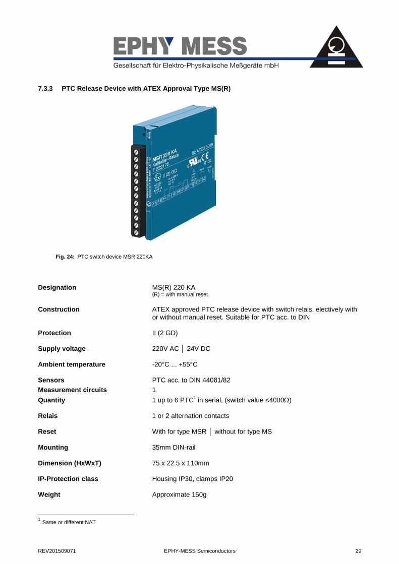
7.3.3 PTC Release Device with ATEX Approval Type MS(R)
Fig. 24: PTC switch device MSR 220KA
Designation MS(R) 220 KA (R) = with manual reset
Construction ATEX approved PTC release device with switch relais, electively with or without manual reset. Suitable for PTC acc. to DIN
Protection II (2 GD)
Supply voltage 220V AC │ 24V DC
Ambient temperature -20°C ... +55°C
Sensors PTC acc. to DIN 44081/82
Measurement circuits 1
Quantity 1 up to 6 PTC1 in serial, (switch value <4000)
Relais 1 or 2 alternation contacts
Reset With for type MSR │ without for type MS
Mounting 35mm DIN-rail
Dimension (HxWxT) 75 x 22.5 x 110mm
IP-Protection class Housing IP30, clamps IP20
Weight Approximate 150g
1 Same or different NAT

30 EPHY-MESS Semiconductors REV201509071
7.4 KTY Release Device Type (KTY 04.01-R)
Fig. 25: KTY –release device KTY 04.01-R
Designation Release device KTY 04.01-R
Construction KTY- release device with mains and faults display, self control regarding sensor breaking and voltage breakdown (based on the holding-current principle). Adjustable switchoff temperature. A potential-free relay alteration contact
Supply voltage 230V AC 50Hz (±10%).
Ambient temperature -20°C ... +60°C
Sensors
Type KTY 84-130 / -150 / -151 / -152
Quantity 1
Measuring circuits 1
Relais 1 potential-free alteration contact
Switching capacity 250V AC max. 6A, 300VA ind.
Adjustable switching range 60°C ...+260°C
Switch-back 10K ±2.5K below switchoff temperature
Installation top hat rail and screw mounting
Dimensions 75 x 45 x 107.5mm
IP-Protection class Housing IP40, connection clamps IP00
Weight Approximate 195g

REV201509071 EPHY-MESS Semiconductors 31
Circuit diagram
1 2 3 4 5 6 7 8
Netz
Clamps allocation Sensor clamps: 1 / 2 Polarity
1 1 = (+) colour code: yellow
2 = (-) colour code: green Relay clamps: 4 / 5 / 6 4 / 5 closed if: sensor temperature > adjusted switching temperature sensor or cable breaking breakdown of the supply voltage 4 / 5 opened if: sensor temperature < adjusted switching temperature & supply voltage applied 4 / 6 closed if:
sensor temperature < switching temperature & supply voltage applied
4 / 6 opened if: sensor temperature > adjusted switching temperature sensor or cable breaking breakdown of the supply voltage Power supply: 7 / 8 230VAC / 50-60 Hz
1 Colour code of EPHY-MESS KTY84-1xx sensors

Berta-Cramer-Ring 1D-65205 WiesbadenTel.: 06122 / 9228-0Fax: 06122 / 9228-99www.ephy-mess.de


