
SERV I C E MA NUA L C I T I Z CO F F E E M A CH I N E S
Citiz EF 483/484
Citiz & milk EF 485/486
Citiz & Co EF 487/488
Version 1.2 en

Citiz service manual 2
CONT EN T S
1 General Safety Notes ........................................................................................6
2 Model overview ...................................................................................................7
2.1 Model range ....................................................................................................... 7 2.2 Core unit versions .............................................................................................. 8
3 Main Components ..............................................................................................9 3.1 Overview core unit, D range .......................................................................... 9
3.1.1 Interior view core unit, D range...........................................................10 3.2 Overview core unit, C range ........................................................................ 11
3.2.1 Interior view core unit, C range...........................................................12 3.3 Overview model Citiz ..................................................................................... 13 3.4 Overview model Citiz & milk .......................................................................... 14
3.4.1 Overview milk frother AERO3...............................................................15 3.5 Overview model Citiz & Co ............................................................................ 16 3.6 Fluid System .................................................................................................... 17
3.6.1 Water circuit diagram of core unit (all Citiz versions) ..............................17 3.6.2 Water circuit of models Citiz / Citiz & milk...............................................18 3.6.3 Water circuit of model Citiz & Co ............................................................19
4 Technical Data ..................................................................................................20 4.1 Rating Plates.................................................................................................... 20
4.1.1 Examples of brand specific rating plates ................................................20 4.1.2 Rating plate details .................................................................................23 4.1.3 Rating plate of milk frother (model Citiz & milk) ......................................24
4.2 Summary of technical data............................................................................... 25 4.2.1 Technical data of coffee machines .........................................................25 4.2.2 Technical data of milk frother (model Citiz & milk)..................................27 4.2.3 Dimensions and weight model Citiz ......................................................28 4.2.4 Dimensions and weight model Citiz & milk ...........................................29 4.2.5 Dimensions and weight milk frother ......................................................29 4.2.6 Dimensions and weight model Citiz & Co.............................................30
5 Operation ............................................................................................................31 5.1 General information.......................................................................................... 31 5.2 Status indication............................................................................................... 31
5.2.1 Status indication of coffee machine ........................................................31 5.2.2 Status indication of milk frother AERO3..................................................33
5.3 Machine modes................................................................................................ 34 5.3.1 Machine modes of Citiz coffee machines ...............................................34 5.3.2 Machine modes of milk frother AERO3...................................................35
5.4 Program / reset fill up level............................................................................... 36 5.4.1 Programming the fill up level...................................................................36 5.4.2 Resetting the fill up level .........................................................................36
5.5 Empty water system......................................................................................... 37

Citiz service manual 3
6 Maintenance ...................................................................................................... 38 6.1 Daily maintenance and cleaning ...................................................................... 38
6.1.1 Before first coffee or at the start of day .................................................. 38 6.1.2 After last coffee or at the end of day....................................................... 39 6.1.3 Milk frother of model Citiz & milk ............................................................ 40
6.2 Descaling ......................................................................................................... 41 6.2.1 Descaling procedure for models Citiz and Citiz & milk ........................... 41 6.2.2 Descaling procedure for model Citiz & Co.............................................. 45
7 Troubleshooting ............................................................................................... 49 7.1 Check list for coffee machine (all models) ....................................................... 49 7.2 Check list for milk frother ................................................................................. 51
8 Repairs ............................................................................................................... 52 8.1 Safety instructions ........................................................................................... 52 8.2 Repair and mounting tips ................................................................................. 52 8.3 Tools and accessories ..................................................................................... 55 8.4 Platform disassembly model Citiz.................................................................. 56
8.4.1 General disassembly .............................................................................. 56 8.4.2 Replacing water tank connector ............................................................. 59 8.4.3 Replacing mains switch .......................................................................... 60 8.4.4 Replacing power cord ............................................................................. 62 8.4.5 Removing core unit................................................................................. 64
8.5 Platform disassembly model Citiz & milk ....................................................... 67 8.5.1 General disassembly .............................................................................. 67 8.5.2 Replacing water tank connector ............................................................. 71 8.5.3 Replacing milk frother connector ............................................................ 73 8.5.4 Replacing mains switch .......................................................................... 74 8.5.5 Replacing power cord ............................................................................. 75 8.5.6 Removing core unit................................................................................. 77
8.6 Platform disassembly model Citiz & Co......................................................... 80 8.6.1 General disassembly .............................................................................. 80 8.6.2 Replacing water tank connector ............................................................. 84 8.6.3 Replacing mains switch .......................................................................... 85 8.6.4 Replacing power cord ............................................................................. 87 8.6.5 Removing core units ............................................................................... 89
8.7 Disassembly of core unit, C range................................................................. 91 8.7.1 General disassembly .............................................................................. 91 8.7.2 Replacing compact brewing unit............................................................. 96 8.7.3 Replacing pump...................................................................................... 98 8.7.4 Replacing flow meter ............................................................................ 101 8.7.5 Replacing automatic priming device (APD) .......................................... 102 8.7.6 Replacing thermoblock with NTC sensor and fine wire fuse(s) ............ 104 8.7.7 Replacing electronic control board with button prints ........................... 107
8.8 Disassembly of core unit, D range............................................................... 109 8.8.1 General disassembly ............................................................................ 109 8.8.2 Replacing electronic control board with button prints ........................... 116
8.9 Wiring diagrams ............................................................................................. 118 8.9.1 Wiring diagrams model Citiz............................................................... 118 8.9.2 Wiring diagrams model Citiz & milk, EF 485 / 486 ............................. 124 8.9.3 Wiring diagrams model Citiz & Co, EF 487 / 488 ............................... 128

Citiz service manual 4
9 Function tests .................................................................................................130 9.1 Safety instructions.......................................................................................... 130 9.2 Required equipment....................................................................................... 130
9.2.1 Overview ...............................................................................................130 9.2.2 Pressure adapter ..................................................................................131
9.3 Measure flow rate........................................................................................... 132 9.4 Pressure and leakage checks ........................................................................ 133
9.4.1 Preparations..........................................................................................134 9.4.2 Test run.................................................................................................135
9.5 Measure coffee temperature .......................................................................... 136 9.6 Milk frother tests............................................................................................. 138
9.6.1 Measure hot milk temperature ..............................................................138 9.6.2 Measure milk froth ratio ........................................................................138
9.7 NTC temperature sensor functionality............................................................ 139 9.8 Protective earth (PE) continuity test............................................................... 141
9.8.1 What coffee machine has to be tested and when? ...............................141 9.8.2 General .................................................................................................141 9.8.3 Test sequence ......................................................................................142 9.8.4 What to do if the protective earth continuity test fails............................143
9.9 Protective insulation test ................................................................................ 144 9.9.1 What coffee machines have to be tested and when? ...........................144 9.9.2 General .................................................................................................144 9.9.3 Test sequence ......................................................................................145 9.9.4 What to do if the insulation test fails .....................................................147
10 Explosion Drawings ......................................................................................148 10.1 Model Citiz, core unit D range (EF 483)....................................................... 148 10.2 Model Citiz, core unit C range (EF 484)....................................................... 149 10.3 Model Citiz & milk, core unit D range (EF 485)............................................ 150 10.4 Model Citiz & milk, core unit C range (EF 486)............................................ 151 10.5 Model Citiz & Co, core unit D range (EF 487).............................................. 152 10.6 Model Citiz & Co, core unit C range (EF 488).............................................. 153
11 Parts List ..........................................................................................................154
12 Notes .................................................................................................................158

Citiz service manual 5
PRE F A CE
The purpose of this service manual is to provide the service personnel with all necessary information with regards to correct handling, maintenance and repair of the Citiz coffee machine types EF 483/484, EF 485/486 and EF 487/488.
This manual should be used by the technicians as a valuable aid to guarantee the permanent readiness for use of the machines. In order to take full advantage of all the functions, it is absolutely necessary to follow the instructions in this manual.
For fast access to information directly from the PC or MAC monitor, this service manual is available as PDF file and can be downloaded from the Nespresso technical website under https://business.nespresso.com.
The required utility software to read PDF files (Adobe Reader ® ) for PCs and MAC computers can be downloaded (under http://www.adobe.com) for free please click the logo:
CONT EN T U PD A TE S
Version 1.2
• Chapter "Function tests": correction of the protective insulation test (connection of the test equipment to both neutral and phase pins instead of ground pin). See subtitle "Test sequence" on page 145, steps 1 till 3 (connection of the measuring cable).
• Service manual is available in additional languages: French, German, Spanish and Italian
Version 1.1
• First released service manual version, in English only.
Version 1.0
• Test version for proofreading, in English only.
Please keep this manual together with the corresponding
service documentation. This way you are assured to have the necessary information.
2 PDF versions of this service manual can be selected:
• A highly compressed version with low picture resolution and small file size.
• A version in print quality with hyperlinks, but with big file size.
The version number of this service manual is printed on the lower
right corner of the front page.

Citiz service manual 6
G E N E R A L S A F E T Y N O T E S
1 G EN ERA L S A FE T Y NO T E S
As an additional safety measure, the use of a residual current device (RCD), also called the ground fault circuit interrupter (GFCI), in the repair centre is highly recommended.
Risk of fatal electrical shock and fire!
Mains voltage inside the coffee machine. • Unplug appliance before cleaning. • Never clean wet or immerse plug, cord or appliance in any fluid. • Disconnect the mains plug before disassembly the appliance must
be free of voltage.
This device does not protect against electrical shock due
to contact with both cir cuit conductors.
Example illustrations of typical devices.
Use a GFCI with a trip level of 4 6 mA (USA) resp. a RCD with a trip
level of 15 30 mA (Europe). A trip level above 30 mA provides only very limited protection against harm from an electric shock.
1) RCD protected socketoutlet 2) Plugin RCD unit
3) GFCI socket 4) Plugin GFCI
Danger of burns!
Hot parts and water under pressure inside the coffee machine (particularly in the thermoblock). • Let coffee machine cool down before cleaning or disassembly.

Citiz service manual 7
M O D E L O V E R V I E W
2 MODE L O V ERV I EW
2.1 Model range
With core unit Drange: With core unit Crange:
Each model has a special platform is available in 2 different designs, depending on the core unit version (C or Drange).
1) Citiz 2) Citiz & milk
3) Citiz & Co
A core unit is the actual coffee machine, mounted on
a platform.

Citiz service manual 8
M O D E L O V E R V I E W
2.2 Core unit versions
Drange Crange This comparison helps to identify the core unit version.
1) Coffee outlet 2) Closing handle
3) Coffee buttons 4) Cup holder
There are additional differences between the 2 versions (cov
ers, wiring etc.) not men tioned in the table.
Different components Drange Crange
Coffee outlet (1) contured coffee outlet "flat" coffee outlet
Closing handle (2) chromiumplated closing handle black closing handle
Coffee buttons (3) arranged on both sides of the closing handle
arranged behind the closing handle
Cup holder (4) cup holder with slotted recesses cup holder with circular recesses

Citiz service manual 9
M A I N C O M P O N E N T S
3 MA I N COMPON ENT S
3.1 Overview core unit, Drange For platform compo nents refer to model overview.
1) Cup support 2) Waste water container 3) Capsule container (used capsules) 4) Coffee nozzle 5) Steam cover 6) Closing handle
7) Button "small cup" (Espresso) 8) Button "large cup" (Lungo) 9) Side panels left/right 10) Rear cover

Citiz service manual 10
M A I N C O M P O N E N T S
3.1.1 Interior view core unit, Drange
1) Button prints 2) Capsule bay 3) Brewing unit (TMBU, Tolkien Mini
Brewing Unit) 4) Pump (Invensys CP4/SP) 5) Flowmeter (FHKSC12)
6) Electronic control board (with protective covers)
7) Self priming device (APD) 8) NTC temperature sensor 9) Thermoblock (EF 2003)
Citiz service manual 11
M A I N C O M P O N E N T S
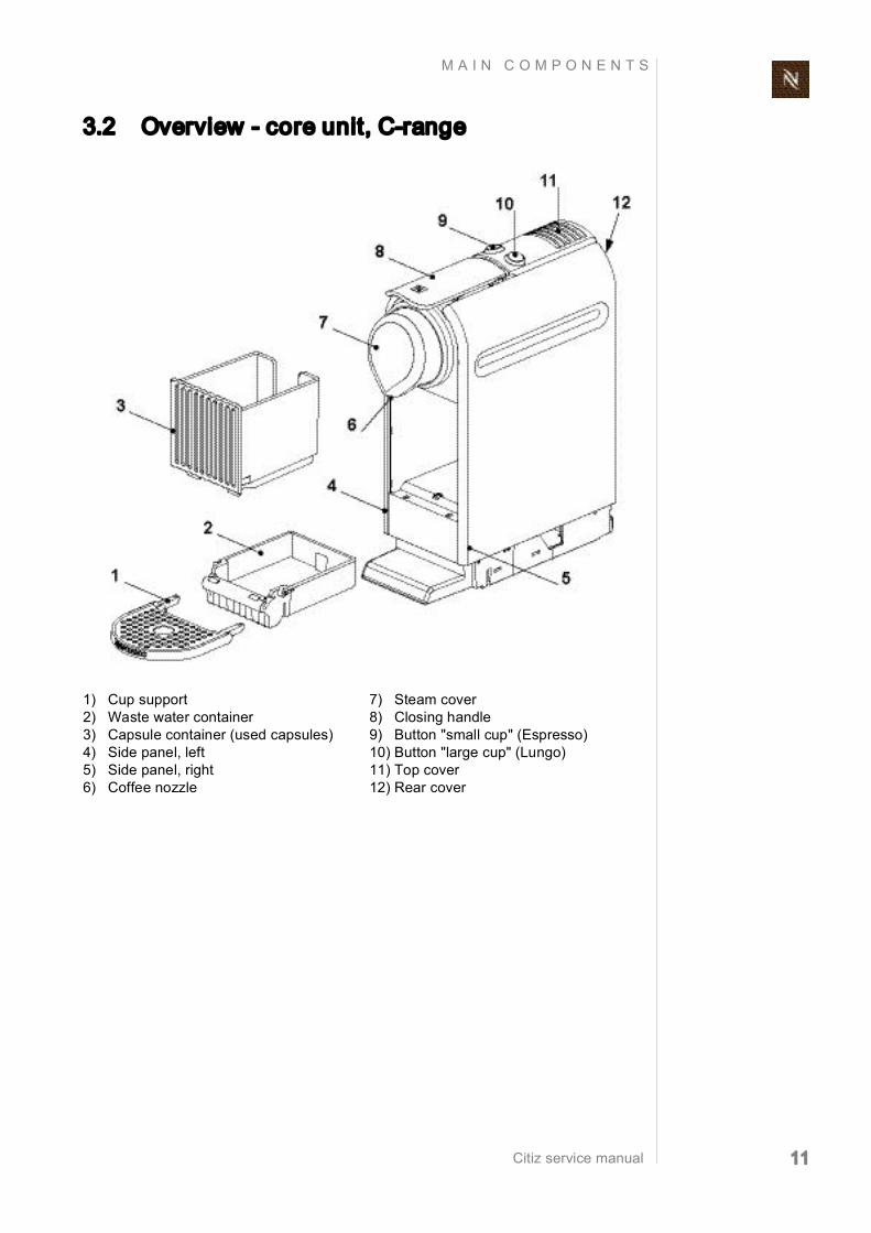
3.2 Overview core unit, Crange
1) Cup support 2) Waste water container 3) Capsule container (used capsules) 4) Side panel, left 5) Side panel, right 6) Coffee nozzle
7) Steam cover 8) Closing handle 9) Button "small cup" (Espresso) 10) Button "large cup" (Lungo) 11) Top cover 12) Rear cover
Citiz service manual 12
M A I N C O M P O N E N T S
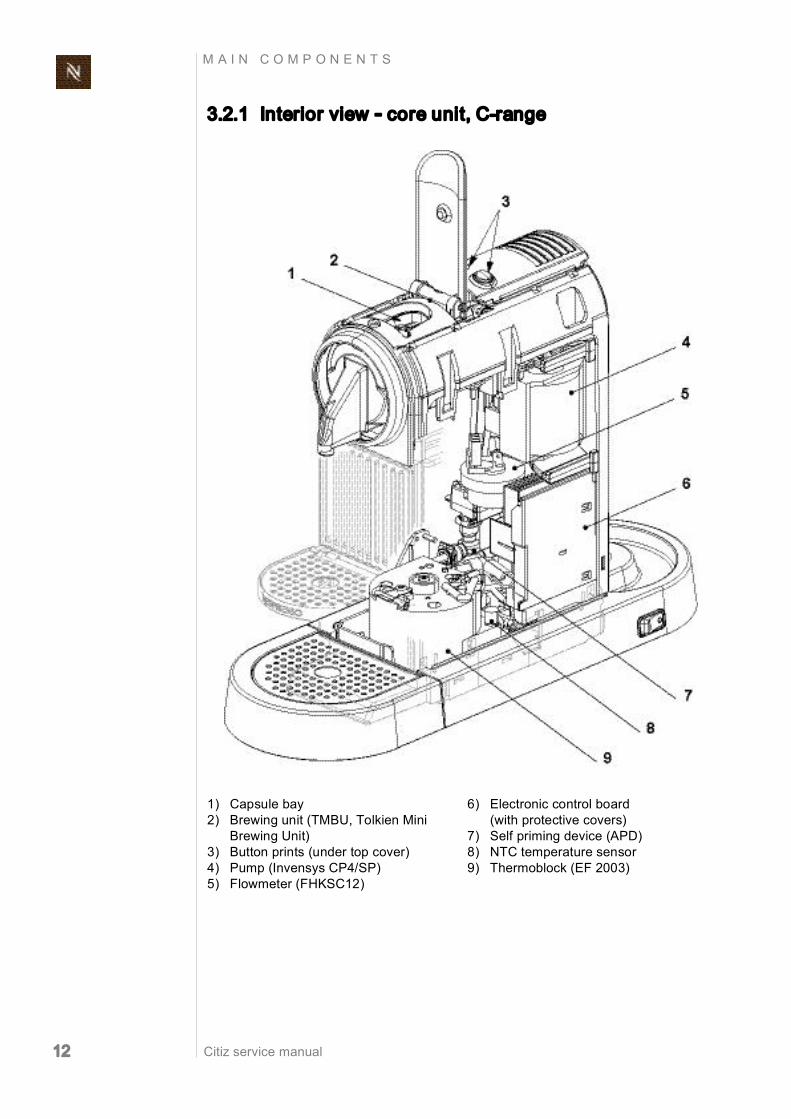
3.2.1 Interior view core unit, Crange
1) Capsule bay 2) Brewing unit (TMBU, Tolkien Mini
Brewing Unit) 3) Button prints (under top cover) 4) Pump (Invensys CP4/SP) 5) Flowmeter (FHKSC12)
6) Electronic control board (with protective covers)
7) Self priming device (APD) 8) NTC temperature sensor 9) Thermoblock (EF 2003)

Citiz service manual 13
M A I N C O M P O N E N T S
3.3 Overview model Citiz
This is the basic model with the smallest platform (9).
The drip grid (1) exists in 2 versions, matches with the cup holder of the core unit version (e.g. circular recesses).
This model is pictured with a Crange core unit.
1) Drip grid 2) Drip tray 3) Core unit (e.g. Crange) 4) Water tank cover 5) Water tank
6) Water tank connector 7) Power cord 8) ON/OFF switch (mains switch) 9) Platform
The core units of model Citiz and Citiz & milk are not com
patible due to different electronic control boards.
Citiz service manual 14
M A I N C O M P O N E N T S
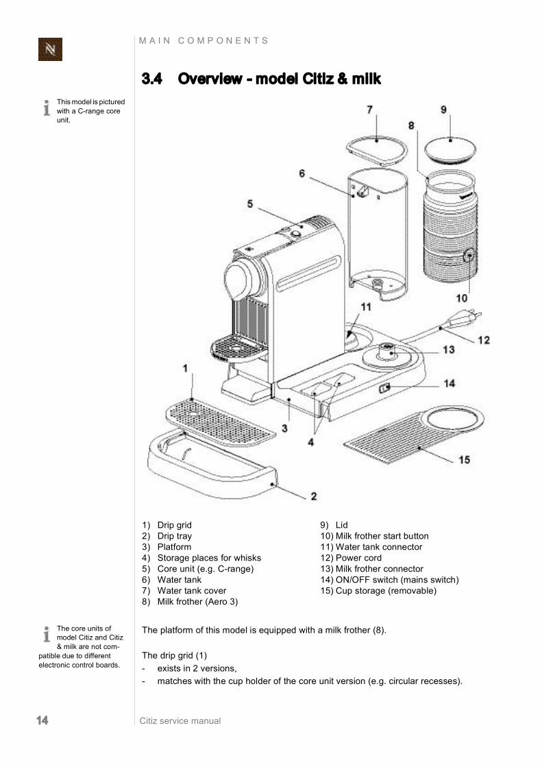
3.4 Overview model Citiz & milk
The platform of this model is equipped with a milk frother (8).
The drip grid (1) exists in 2 versions, matches with the cup holder of the core unit version (e.g. circular recesses).
This model is pictured with a Crange core unit.
1) Drip grid 2) Drip tray 3) Platform 4) Storage places for whisks 5) Core unit (e.g. Crange) 6) Water tank 7) Water tank cover 8) Milk frother (Aero 3)
9) Lid 10) Milk frother start button 11) Water tank connector 12) Power cord 13) Milk frother connector 14) ON/OFF switch (mains switch) 15) Cup storage (removable)
The core units of model Citiz and Citiz & milk are not com
patible due to different electronic control boards.

Citiz service manual 15
M A I N C O M P O N E N T S
3.4.1 Overview milk frother AERO3
The inside of the jug (3) has level marks (6), is surfacecoated for easy cleaning.
The milk frother AERO3 is part of the standard equipment
of the model Citiz & milk.
1) Lid 2) Seal 3) Jug 4) Power plug 5) Start button (red/blue backlighted)
6) Indication of 2 max. milk levels (120 ml/240 ml)
7) Mixer for hot milk 8) Spring whisk for milk foam

Citiz service manual 16
M A I N C O M P O N E N T S
3.5 Overview model Citiz & Co
The drip grid (1) exists in 2 versions, matches with the cup holder of the core unit version (e.g. circular recesses).
This model is pictured with a Crange core unit.
1) Drip tray 2) Drip grid 3) ON/OFF switch (mains switch) 4) Power cord
5) Core units (e.g. 2 x Crange) 6) Water tank 7) Water tank cover 8) Platform

Citiz service manual 17
M A I N C O M P O N E N T S
3.6 Fluid System
3.6.1 Water circuit diagram of core unit (all Citiz versions)
Legend:
The self priming device (4) allows the pump to suck water when it is filled with air (new machine, empty water
tank etc.) removes air bubbles from the water circuit feeds a water/air mix back into the water tank.
1) Water tank 2) Flow meter 3) Pump 4) Self priming device 5) Thermoblock
6) Mini brewing unit (MBU) 7) Capsule container 8) Waste water container 9) Drip tray
Fresh cold water
Fresh hot water
Coffee
Waste/drip water
Citiz service manual 18
M A I N C O M P O N E N T S
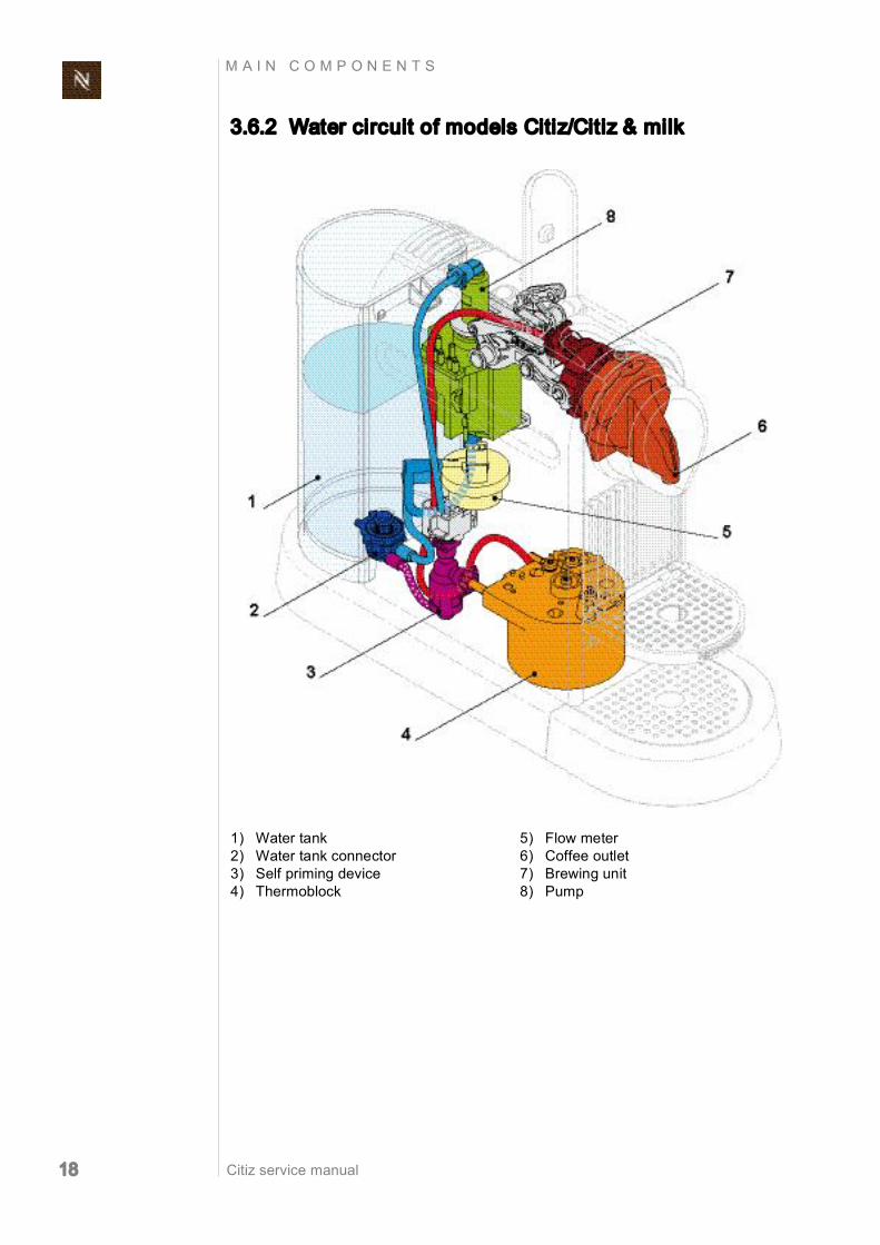
3.6.2 Water circuit of models Citiz/Citiz & milk
1) Water tank 2) Water tank connector 3) Self priming device 4) Thermoblock
5) Flow meter 6) Coffee outlet 7) Brewing unit 8) Pump
Citiz service manual 19
M A I N C O M P O N E N T S
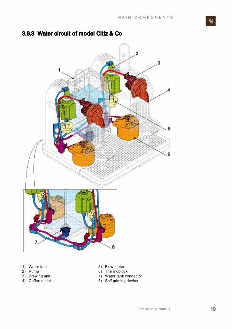
3.6.3 Water circuit of model Citiz & Co
1) Water tank 2) Pump 3) Brewing unit 4) Coffee outlet
5) Flow meter 6) Thermoblock 7) Water tank connector 8) Self priming device

Citiz service manual 20
T E C H N I C A L D A T A
4 T E CHN I C A L D A T A
4.1 Rating plates
4.1.1 Examples of brand specific rating plates
Nespresso, EUversion
The type plate can be found at the bottom of the coffee machine’s
platform.
This overview shows examples of various brands and is subject
to alterations.
EF484 Citiz C110 red EF483 Citiz D110 black
EF486 Citiz & milk C120 red EF485 Citiz & milk D120 black
EF488 Citiz & Co C130 red EF487 Citiz & Co D130 black

Citiz service manual 21
T E C H N I C A L D A T A
DeLonghi, EUversion
Koenig, CHversion
EF483 Citiz D110 Limousine black/DeLonghi EN165.B EF483 Citiz D110 60's White/DeLonghi EN165.CW
EF485 Citiz & milk D120 Limousine black/DeLonghi EN265.BAE
EF487 Citiz & Co. D130 Limousine black/DeLonghi EN325.B
EF483 Citiz D110 Limousine black/Koenig Citiz EF483 Citiz D110 60's White/Koenig Citiz
EF485 Citiz & milk D120 Limousine black/Koenig Citiz & milk EF487 Citiz & Co. D130 Limousine black/Koenig Citiz & Co.

Citiz service manual 22
T E C H N I C A L D A T A
Krups, EUversion
Magimix, EUversion
EF484 CitiZ XN700510 grey EF484 CitiZ XN700610 red
EF486 CitiZ & milk XN710610 red EF488 CitiZ & Co XN750510 grey
EF483 Citiz M190 Ref 11290 black EF483 Citiz M190 Ref 11291 cream
EF485 Citiz M190 Milk Ref 11300 black EF487 Citiz M190 Duo Ref 11305 black

Citiz service manual 23
T E C H N I C A L D A T A
Turmix, ATversion
4.1.2 Rating plate details
EF484 Citiz C110 fire engine red/ Turmix TX 170 Citiz EF484 Citiz C110 steel grey/Turmix TX 170 Citiz
EF486 Citiz & milk C120 fire engine red/ Turmix TX 270 Citiz & milk
EF488 Citiz & Co. C130 steel grey/ Turmix TX 370 Citiz & Co.
1) Brand name 2) Voltage and power rating 3) Place of manufacture 4) National approval sign of Russia
(GOST R) 5) National approval sign of Germany
(VDE) 6) Barcode
7) Serial number 8) Machine type 9) Special disposal icon
(do not dispose with ordinary waste) 10) Sign of conformity (CE) 11) Conform with RoHS guidelines (lead
free solder, etc.) 12) Article number of the rating plate

Citiz service manual 24
T E C H N I C A L D A T A
Decoding the alphanumeric serial number
Example:
4.1.3 Rating plate of milk frother (model Citiz & milk)
By decoding the date of production and machine type, the
coffee machine can be identified exactly.
Checksum (if available) Color version Type of mains plug Mains voltage Distributing partner Incremental number per production day Manufacturing plant Manufacturer designation of the machine type (EF 484) 08312 ... Date of production (08 = year 2008, 312 = 312 day of the year)
Note he mains volt age ranges of the dif ferent models.

Citiz service manual 25
T E C H N I C A L D A T A
4.2 Summary of technical data
4.2.1 Technical data of coffee machines Mains voltage ranges Mains voltage for Citiz Europe, RU, AU, CN, KR, SG, HK, ME, ZA, IL, BR, AR........... 220240 V / 5060 Hz USA, Canada, BR, MX .............................................................. 120127 V / 5060 Hz Japan .............................................................................................. 100 V / 5060 Hz*
Mains voltage for Citiz & milk Europe, RU, AU, CN, KR, SG, HK, ME, ZA, IL, BR, AR........... 220240 V / 5060 Hz USA, Canada, BR, MX .............................................................. 120127 V / 5060 Hz
Mains voltage for Citiz & Co Europe, RU, AU, ME, IL............................................................ 220240 V / 5060 Hz
Approvals Approvals for Citiz ........................ CE, UL "for USA and Canada", PSE, Gost R, Ctick,
CCC, KTL, SPRING, SASO, SABS, ISI, IRAM, NOM
Approvals for Citiz & milk ............ CE, UL "for USA and Canada", Gost R, Ctick, CCC, KTL, SPRING, SASO, SABS, ISI, IRAM, NOM
Approvals for Citiz & Co .................................................. CE, Gost R, Ctick, SASO, ISI
Power ratings of coffee machine main components (for all voltages and frequencies) Thermoblock .....................................................................................................1200 W*
*model Citiz & Co, Australia: 1080 W Pump................................................................................................................. 55/60 W
Performance data of core unit Heating up Citiz ...................................................................................................... approx. 7.6 Wh Citiz & milk ........................................................................................... approx. 7.6 Wh Citiz & Co........................................................................................... approx. 14.9 Wh
1 small cup (40 ml*) Citiz ...................................................................................................... approx. 4.3 Wh Citiz & milk ........................................................................................... approx. 4.3 Wh Citiz & Co (both heads)........................................................................ approx. 7.6 Wh * Default setting
Technical data are valid for all Citiz mod els unless explicitly
stated otherwise.

Citiz service manual 26
T E C H N I C A L D A T A
1 large cup (110 ml*) Citiz ...................................................................................................... approx. 8.7 Wh Citiz & milk ........................................................................................... approx. 8.7 Wh Citiz & Co (both heads) ...................................................................... approx. 14.8 Wh * Default setting
Standby operation (in 1 hour) Citiz ...................................................................................................... approx. 0.7 Wh Citiz & milk ........................................................................................... approx. 0.7 Wh Citiz & Co ............................................................................................. approx. 2.2 Wh
Pump Pump pressure Max. permissible .............................................................................. 17.5 bar ± 1.5 bar During coffee preparation (depending on the type of coffee)..........................916 bar Flow performance.................................................................. 120240 ml/min. at 12 bar
Capacities Water tank Citiz ........................................................................................................................1.0 l Citiz & milk .............................................................................................................1.0 l Citiz & Co ...............................................................................................................1.4 l
Drip tray Citiz ....................................................................................................................100 ml Citiz & milk .........................................................................................................180 ml Citiz & Co ...........................................................................................................250 ml
Capsule container Citiz, Citiz & milk .................................................................................... 911 capsules Citiz & Co ........................................................................................2x (912) capsules
Temperatures Operating temperature ................................................................... + 5 °C up to + 45 °C Storage temperature ..................................................................... 25 °C up to + 60 °C Safety temperature (thermal cutoff) ................................................................... 167 °C Coffee temperature at outlet....................................................................... 86 °C ± 3 °C
Various data Noise during brewing cycle ....................................................................max. 60 dB(A)*
* model Citiz & milk: measured without milk frother * model Citiz & Co: measured with only one core unit running
Preheating time .......................................................................................approx. 60 sec Cable length .............................................................................................. approx. 1.2m
Advised water tank capacities to avoid spilling.

Citiz service manual 27
T E C H N I C A L D A T A
4.2.2 Technical data of milk frother (model Citiz & milk) Mains voltage Europe ........................................................................................ 220240 V / 5060 Hz USA/Canada ................................................................................ 120127 V / 5060 Hz
The milk frother is available in 2 different models, depending on above mains voltage ranges, has to match the mains voltage range of the associated coffee machine.
Power rating (depending on mains voltage) 220240 V, 5060 Hz..................................................................................... 410490 W 110127 V, 5060 Hz..................................................................................... 380505 W Standby operation ............................................................................................... < 1 W
Power consumption
Capacity Hot milk ...................................................................................................... max. 240 ml Hot/cold milk for milk froth...........................................................................max. 130 ml
If replacing a defect milk frother, check mains voltage range.
Preparation Voltage 120 V 127 V 220 V 230 V 240 V Unit
Froth milk: hot (starting with cold device)
Measured power W 452 506 407 445 485
Intensity A 3.77 3.98 1.85 1.93 2.02
Consumption for 2 test preparations Wh 19 19 19 19 19
Froth milk: cold (starting with cold device)
Measured power W 1.98 2.24 2.72 2.80 3.01
Intensity of current (cos. = 0.58) A 40.93 44 30.82 27.51 25.97
Consumption for 2 test preparations Wh 0.08 0.09 0.11 0.12 0.13
Hot milk (starting with cold device)
Measured power W 452 506 407 445 485
Intensity of current A 3.77 3.98 1.85 1.93 2.02
Consumption for 2 test preparations Wh 37 37 37 37 37
Citiz service manual 28
T E C H N I C A L D A T A
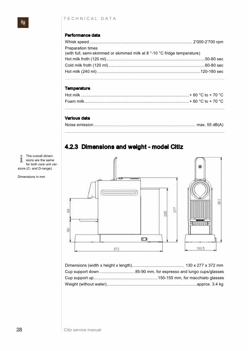
Performance data Whisk speed......................................................................................... 2’0002’700 rpm Preparation times (with full, semiskimmed or skimmed milk at 8 °10 °C fridge temperature) Hot milk froth (120 ml) .....................................................................................5080 sec Cold milk froth (120 ml) ...................................................................................6080 sec Hot milk (240 ml) .........................................................................................120180 sec
Temperature Hot milk ............................................................................................. + 60 °C to + 70 °C Foam milk.......................................................................................... + 60 °C to + 70 °C
Various data Noise emission ........................................................................................ max. 55 dB(A)
4.2.3 Dimensions and weight model Citiz
Dimensions (width x height x length)............................................. 130 x 277 x 372 mm Cup support down .............................. 8590 mm, for espresso and lungo cups/glasses Cup support up.......................................................150155 mm, for macchiato glasses Weight (without water)..............................................................................approx. 3.4 kg
The overall dimen sions are the same for both core unit ver
sions (C and Drange).
Dimensions in mm

Citiz service manual 29
T E C H N I C A L D A T A
4.2.4 Dimensions and weight model Citiz & milk
Dimensions (width x height x length) ............................................ 237 x 277 x 372 mm Weight (without water, milk frother included) ...........................................approx. 4.6 kg
4.2.5 Dimensions and weight milk frother
Dimensions of jug cpl. (diameter x height) ................................................ 91 x 170 mm Whisk for foam (diameter x height) ..............................................................33 x 32 mm Mixer for hot milk.................................................................................. 15 x 34 x 32 mm Weight (with whisk and mixer) ..............................................................................0.7 kg
The overall dimen sions are the same for both core unit ver
sions (C and Drange).
Dimensions in mm

Citiz service manual 30
T E C H N I C A L D A T A
4.2.6 Dimensions and weight model Citiz & Co
Dimensions (width x height x length)............................................. 326 x 281 x 286 mm Weight (without water).................................................................................approx. 7 kg
The overall dimen sions are the same for both core unit ver
sions (C and Drange).
Dimensions in mm.

Citiz service manual 31
O P E R A T I O N
5 O P ERA T I ON
5.1 General information For an overview of operational controls see “Main Components” on page 9. For basic operation of the machine such as preparing a coffee and other related infor mation, refer to the user manual. To simplify matters, the model Citiz with core unit Crange is used to exemplify throughout this chapter.
5.2 Status indication
5.2.1 Status indication of coffee machine The two coffee buttons with green LED backlight show the status of the coffee machine according to the following table:
Machine status etc. "Small cup" button
"Large cup" button LED signal
Off Both LED‘s off
Self test Blinking 1 Hz, 0.5 s on, 0.5 s off
Error
Blinking fast (2 Hz, 0.25 s on/0.25 s off) 3 times every 2 sec onds
Heat up Blinking 1 Hz, 0.5 s on, 0.5 s off
Ready Both LED‘s on
Brewing small cup Blinking 1 Hz, 0.5 s on, 0.5 s off
Brewing big cup Blinking 1 Hz, 0.5 s on, 0.5 s off
Rinse small cup
Blinking 1 Hz, 0.5 s on, 0.5 s off (same as brewing small cup)
Rinse big cup
Blinking 1 Hz, 0.5 s on, 0.5 s off (same as brewing big cup)

Citiz service manual 32
O P E R A T I O N
Volume brewing small cup
Blinking 1 Hz, 0.5 s on, 0.5 s off (same as brewing small cup)
Volume brewing big cup
Blinking 1 Hz, 0.5 s on, 0.5 s off (same as brewing big cup)
Descaling ready Blinking 2 Hz, 0.25 s on, 0.25 s off
Descaling pump on (descal)
Blinking 2 Hz, 0.25 s on, 0.25 s off (same as descaling ready mode)
Descaling pump off (descal)
Blinking 2 Hz, 0.25 s on, 0.25 s off (same as descaling ready mode)
Emptying / Evaporating Blinking 2 Hz, 0.25 s on, 0.25 s off
Standby Blinking 0.5 Hz, 1 s on, 1 s off alternately
Resetting Blinking 2 Hz, 0.25 s on, 0.25 s off indication for 3 s
Power save Blinking 0.2 Hz, 2.5 s on, 2.5 s off alternately
Overheat Blinking 1 Hz, 0.5 s on, 0.5 s off (same as heat up)
Power save activation Blinking 0.5 Hz, 1 s on, 1 s off alternately 5 times
Machine status etc. "Small cup" button
"Large cup" button LED signal

Citiz service manual 33
O P E R A T I O N
5.2.2 Status indication of milk frother AERO3 The operating button with red/blue backlight shows the status of the milk frother according to the following table:
Power save deactivation (only for model Citiz & Co)
Blinking 0.5 Hz, 1 s on, 1 s off alternately 3 times
Machine status etc. "Small cup" button
"Large cup" button LED signal
To reset a red blink ing backlight:
1. Remove milk frother from platform. 2. Remove cause of failure if possible.
Machine status etc. Operating button Light signal
Off Backlight off
On hot milk preparation Red backlight on
On cold milk froth prepara tion Blue backlight on
Failure/malfunction (e.g. overheating because of burnt milk, too less or no milk)
Blinking red backlight (1 Hz, 0.5 s on, 0.5 s off)
Failure: milk frother has wrong mains voltage range
Fast blinking red backlight (2 Hz, 0.25 s on, 0.25 s off

Citiz service manual 34
O P E R A T I O N
5.3 Machine modes
5.3.1 Machine modes of Citiz coffee machines This table helps to understand the operating modes of a Citiz coffee machine:
Machine mode Enter mode Actions Exit mode
1 Heat up mode Every time after switch ing on machine
Heats up thermoblock to ready temperature 90 °C within 60 s with out overshooting target temperature
e.g. switching off machine
2 Self test mode Every time after switch ing on machine
Tests: • NTC short circuit • NTC connected • Thermoblock heating curve
Error handling: Tracking of the last 5 errors by a ring buffer
e.g. switching off machine
3 Ready mode
• After heat up and self test mode was ok
• After brewing or volume brewing coffee
• After reset mode • After leaving descaling mode
Keeps thermoblock temperature at 90 °C
e.g. switching off machine
4a Brewing mode 4b Volume brewing
mode (program ming cup size)
• Press and release large or small coffee button (brewing mode)
• Press and hold large or small coffee button for more than 3 s (programming mode)
• Press and release large or small coffee button when machine was in brewing mode or automatic exit given by the flow meter
• Release large or small coffee button when machine was in programming mode
• Switching off machine
5 Descaling mode
• Switch on machine, wait until ready
• Press and hold both coffee buttons for at least 3 s
• Regulate tempera ture to 65 °C (after pump was started)
• Stop and start pump with any coffee button, no volume brewing in descaling mode
• Press and hold both coffee buttons for at least 0.5 s
Note: When machine is switched off during any descaling mode, then it goes to descaling mode ready state after next switch on.

Citiz service manual 35
O P E R A T I O N
5.3.2 Machine modes of milk frother AERO3
6 Emptying mode (evaporing)
1) Switch off machine 2) Press and hold
small coffee button 3) Switch on machine
1) Start pump 2) Stop pump after
10 s 3) Heat up thermo
block to 105 °C (100% power)
4) Switch off ther moblock
5) Go to standby mode
Switch off machine
7 Resetting mode
1) Switch off machine 2) Press and hold
large coffee button 3) Switch on machine
• Reset the programmed large and small coffee volumes to factory setting
• Indicate the resetting mode for 3 s
Factory settings: • small cup .... 40 ml • large cup ... 110 ml
proceeds with self test mode automatically
8 Power save mode
To enable power save mode: 1) Switch off machine 2) Press and hold
both coffee buttons 3) Switch on machine 4) Coffee button
LED‘s blink 5 times alternatively as confirmation
After that automatically after 30 min of non use
• Reduce thermoblock temperature
• Switch LED indica tion to power save mode (blinking alter nately every 2 sec)
Press any coffee but ton to activate ready mode
To disable power save mode: 1) Switch off machine 2) Press and hold
both coffee buttons 3) Switch on machine 4) Coffee button
LED‘s blink 3 times alternatively as confirmation
9 Failure mode
Automatically by fol lowing failures: a) NTC short circuit b) NTC not connected c) Heat up too slow
Machine indicates fail ure with coffee button LED‘s as long as the failure is present
When failure is fixed
10 Standby mode Automatically after emptying mode
• Switch thermoblock off
• Switch LED indica tion to standby mode
Switch off the machine
Machine mode Enter mode Actions Exit mode
1 Hot milk / milk froth preparation
Press start button briefly
Start button lights up red. Milk is heated and mixed.
Automatic switchoff after preparation
2 Cold milk froth prepa ration
Keep start button pressed for approx. 2 sec
Start button lights up blue. Milk is mixed only.
Automatic switchoff after preparation
Machine mode Enter mode Actions Exit mode

Citiz service manual 36
O P E R A T I O N
5.4 Program/reset fill up level Each coffee button can be programmed with a coffee volume for an individual cup size. The procedure for programming/resetting is the same for both coffee buttons.
5.4.1 Programming the fill up level Programmable volume range ..........................................................................10750 ml
5.4.2 Resetting the fill up level With the following procedure all programmed fill up levels will be set back to this factory settings: Coffee button "small cup" ....................................................................................... 40 ml Coffee button "large cup" ..................................................................................... 110 ml
Each new program ming cycle starts with the min. volume
(10 ml after 3 sec), regard less of a preprogrammed coffee volume.
1) Prepare coffee as usual (see user manual), but keep the coffee button pressed for at least 3 seconds in order to start programming mode.
2) Only release the button when the desired fill level is reached.
1) Switch off the coffee machine. 2) Press and hold the "large cup" button. 3) Switch on the coffee machine. 4) Release "large cup" button.

Citiz service manual 37
O P E R A T I O N
5.5 Empty water system After every operation, some water remains in the coffee machine. Therefore the water system must be emptied if the coffee machine will not be used for a long time as antifreeze measure for repairs and shipment.
1) Switch off coffee machine. 2) Remove water tank. 3) Place a beaker under the coffee out
let. Model Citiz & Co: Only one core unit should be emptied at
the same time (danger of mains supply overload).
After this procedure, the coffee machine will not be ready for
approx. 10 min (until the thermoblock cools to below 100 °C ).
4) Press and hold button "small cup". 5) Switch the coffee machine on again. 6) Release button "small cup".
The pump starts to drain the water system and stops automatically.
The coffee buttons blink fast simulta neously.
7) After automatic stop, switch off the coffee machine.

Citiz service manual 38
M A I N T E N A N C E
6 M A I N TEN A NCE
6.1 Daily maintenance and cleaning
6.1.1 Before first coffee or at the start of day The Citiz model is shown as example. Maintain and clean
other models accordingly.
1) Fill water tank with fresh potable water.
2) Insert water tank. 3) For model Citiz & milk:
Attach whisk to milk frother. Place milk frother on base plate connector.
4) Switch machine on.
After a longer period of non use: 5) Place a container under coffee outlet.
6) Rinse coffee machine by pressing but ton "large cup" about 6 times.

Citiz service manual 39
M A I N T E N A N C E
6.1.2 After last coffee or at the end of day
Risk of fatal electrical shock and fire! Never clean wet or immerse plug, cord or appliance in any fluid. Unplug appliance and let it cool down to avoid burns.
Platform and drip tray surfaces are not abrasionproof.
Never use brushes and/or cleaning agents that con tain aggressive or chemical components resp. sol vents. Do not put any part in a dishwasher. Use only a damp cloth or sponge and a mild cleaning agent if necessary
1) Switch machine off. 2) Check if capsule is ejected.
3) Empty and clean capsule container (a) waste water container with cup support (b) drip tray with drip grid (c).
Do not use a brush the water tank can be scratched.
4) Empty, rinse and clean water tank. 5) Reassemble coffee machine. 6) Clean coffee machine with a damp
cloth if necessary.

Citiz service manual 40
M A I N T E N A N C E
6.1.3 Milk frother of model Citiz & milk
Risk of damage! The inside of the jug is coated for easy cleaning. Never use brushes and/or cleaning agents that contain abrasive or aggressive, chemical components resp. solvents. Do not put any part in a dishwasher. Use only a damp cloth and a mild cleaning agent if necessary.
1) Remove milk frother from platform. 2) Remove lid and dismantle whisk.
Keep connectors dry (on platform and
at underside of milk frother).
3) Remove seal from lid. 4) Rinse and clean milk frother together
with whisk or mixer, lid and seal.
5) Clean outside of milk frother with a damp cloth if necessary.
6) Reassemble milk frother.

Citiz service manual 41
M A I N T E N A N C E
6.2 Descaling
Use this chart to inform a customer when to descale the coffee machine depending on local water hardness and average coffee consumption. Double the estimated time interval for model Citiz & Co.
6.2.1 Descaling procedure for models Citiz and Citiz & milk
Only use Nespresso descaler or descaling kit never use vinegar! Descaler can damage casing and contact surfaces. Immediately clean drops of descaling solution.
The descaling chart is based on a cup size of 40 ml.
fH ... French grade dH ... German grade CaCO 3 ... Calcium carbonate
The Citiz model is shown as example.
1) Eject capsule or check if capsule is removed.
2) Remove and empty capsule/waste water container, drip tray and water tank.

Citiz service manual 42
M A I N T E N A N C E
Observe the safety instructions on the descaler package.
Use a container with a capacity of 1 l min.
3) Reassemble coffee machine without water tank.
4) Place a container on the cup support.
5) Fill the water tank with 0.1 l decalcifier (1 bag) and 0.5 l water.
6) Insert water tank into the coffee machine.
7) Press both coffee buttons simulta neously for at least 3 sec.
8) The machine is in descaling mode now (both buttons blinking fast).

Citiz service manual 43
M A I N T E N A N C E
Danger! Hot splashes of descaling solution.
Do not open handle dur ing descaling process.
9) Press any button to start pump. Let the entire solution in the tank run through the system.
10) After water tank is empty, pour descal ing solution back into water tank.
11) Place empty container back on cup support.
12) Descale again: press any button and wait until water tank is empty.

Citiz service manual 44
M A I N T E N A N C E
Danger of injury! Residual descaler may be harmful.
Rinse thoroughly to remove any residue.
13) Empty container and put it back on cup support.
14) Rinse and clean water tank thoroughly and fill it with fresh potable water.
15) Rinse coffee machine by pressing any button and wait until water tank is empty.
16) Press both coffee buttons simultane ously for at least 3 sec to end descal ing mode.
17) Remove and empty container.
18) Switch off coffee machine. 19) Empty and clean capsule/waste water
container and drip tray. 20) Clean coffee machine with a damp
cloth if necessary.

Citiz service manual 45
M A I N T E N A N C E
6.2.2 Descaling procedure for model Citiz & Co
1) Eject capsules or check if capsules are removed.
2) Remove and empty capsule/waste water containers, drip tray and water tank.
Observe the safety instructions on the descaler package.
Use containers with a capacity of 1 l min.
3) Reassemble coffee machine without water tank.
4) Place a container under each coffee outlet.
5) Fill the water tank with 0.2 l decalcifier (2 bags) and 1.0 l water.
6) Insert water tank into the coffee machine.

Citiz service manual 46
M A I N T E N A N C E
7) Press both coffee buttons simulta neously for at least 3 sec. on first core unit.
8) Repeat procedure with second core unit.
9) The machine is in descaling mode now (both coffee buttons blinking fast on core units).
Danger of injury! Hot splashes of descaling solution.
Do not open handles dur ing descaling process.
10) Press any button on a core unit to start pumps. Let the entire solution in the tank run through the system.
11) After water tank is empty, pour descal ing solution from both containers back into water tank.

Citiz service manual 47
M A I N T E N A N C E
12) Place empty containers back on cup supports.
13) Descale again: press any button on a core unit and wait until water tank is empty.
14) Empty containers and put them back on cup supports.
15) Rinse and clean water tank thoroughly and fill it with fresh potable water.
16) Rinse coffee machine by pressing any button on first core unit.
17) Repeat procedure on second core unit and wait until water tank is empty.
Citiz service manual 48
M A I N T E N A N C E
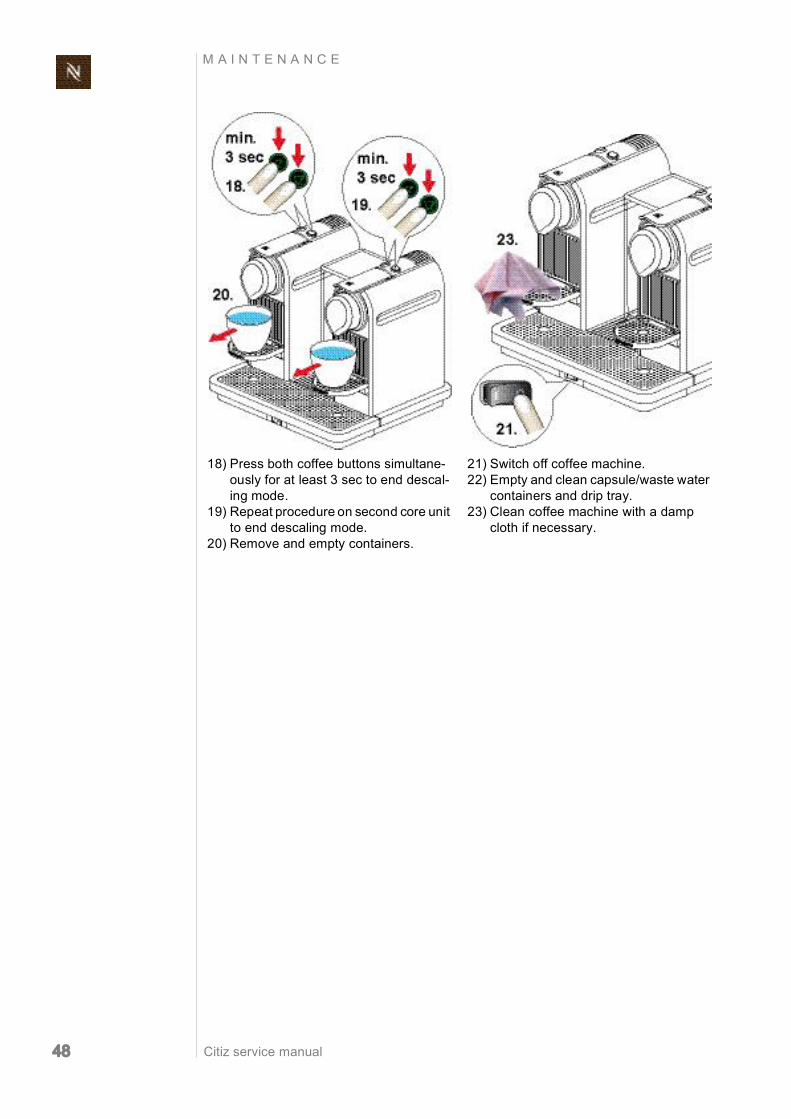
18) Press both coffee buttons simultane ously for at least 3 sec to end descal ing mode.
19) Repeat procedure on second core unit to end descaling mode.
20) Remove and empty containers.
21) Switch off coffee machine. 22) Empty and clean capsule/waste water
containers and drip tray. 23) Clean coffee machine with a damp
cloth if necessary.

Citiz service manual 49
T R O U B L E S H O O T I N G
7 T ROUB L E SHOOT I NG
7.1 Check list for coffee machine (all models)
After an initial inspec tion in accordance with this check list,
errors are quickly found and corrected with the appropri ate measure. Therefore, adhere to the sequence of the check list. Repair every occurring error and work the check list through until it is completed.
Check Error symptoms Measure / repair work
Further measures / repair work
1 Check the coffee machine for visi ble damage
1.1 Housing parts bro ken or damaged
YES replace housing parts if necessary NO continue
1.2 Power cord dam aged
YES replace power cord NO connect power cord of machine to the mains and con tinue
2 Check mechani cal components
2.1 Cup support does not remain in verti cal position
YES check if the capsule and waste water container are cor rectly inserted and mounted NO continue
YES replace damaged or deformed capsule container and/or waste water container.
2.2 Cup support rattles when folded down
YES check if 2 rubber stop pers are mounted on waste water container NO continue
NO replace stoppers
2.3 Closing handle malfunction
YES it is very difficult or almost impossible to close the handle and to press it all the way down NO continue
YES replace the compact brewing unit
2.4 Closing handle unusual noise dur ing actuation
YES check if damper is mounted underneath closing handle NO continue
NO replace damper
2.5 Capsule is not ejected correctly
YES replace brewing unit (TMBU) NO continue
2.6 Seal on capsule cage is damaged (check seal with your finger)
YES replace brewing unit (TMBU) NO continue
3 Fill water tank 3.1 Water tank leaks YES replace water tank NO continue
4 Activate On/Off switch to perform automatic self test
4.1 Coffee machine is not working (does not function)
a) YES power cord is okay (loose connection)
YES continue NO replace power cord
b) YES On/Off switch is okay YES continue NO replace On/Off switch
c) YES pump works (press a coffee button)
YES continue with point f) NO continue with point d)
d) YES both coffee buttons are working
YES continue NO replace electronic control board
e) YES thermostat on pump is defective
YES replace thermostat NO replace pump
f) YES fine wire fuse(s) (167 °C) on thermoblock defec tive
YES replace electronic con trol board, if necessary replace thermoblock NO continue
g) YES wiring is okay NO continue with point 4.3
YES replace electronic con trol board NO replace defective cables
4.2 Both coffee buttons are blinking 3x fast
YES thermoblock is hot NO self test ok continue
YES replace NTC tempera ture sensor NO replace thermoblock

Citiz service manual 50
T R O U B L E S H O O T I N G
5 Measure coffee temperature dur ing preparation (see page 136)
5.1 No coffee
YES a) water system is empty YES replace self priming device (APD) NO continue
YES b) flow meter blocked YES clean or replace NO continue
YES c) pyramide plate blocked
YES replace the compact brewing unit NO continue
YES d) coffee machine is cal cified NO continue
YES descale coffee machine (see page 41)
5.2 Temperature is too low (below 83°C)
YES descale coffee machine (see page 41) NO continue
5.3 Temperature too high (over 89 °C)
YES replace NTC tempera ture sensor NO continue
6 Check for leakage (see page 133) and measure flow rate (see page 132)
6.1 Compact brewing unit leaks
YES replace compact brew ing unit NO continue
6.2 Hose connections leak
YES replace defective hoses and seals NO continue
6.3 Rate of flow not in the standard range
YES coffee machine is calci fied NO continue with point 9
YES descale coffee machine (see page 41) NO replace pump
7 Descale coffee machine (if necessary)
7.1 Coffee machine is calcified
YES descale coffee machine (see page 41) NO continue with point 9
8 Check water tank contents after des caling and rinising
8.1 Particles of calcium and rust visible in water
YES descale and rinse coffee machine again to clean water circuit (see page 41) NO continue
YES inform customer to des cale coffee machine periodi cally and to use specified des caling product only.
9 Final cleaning (see page 38)
No errors found according to check list?
YES for more information please contact Nespresso Service Division
End of check list
Check Error symptoms Measure / repair work
Further measures / repair work

Citiz service manual 51
T R O U B L E S H O O T I N G
7.2 Check list for milk frother
The milk frother is part of the Citiz & milk model.
Check Error symptoms Measure / repair work
Further measures / repair work
1 Check milk frother and accessory for visible damage
1.1 Lid/seal broken or damaged
YES replace lid/seal NO continue
1.2 Inside coating of jug badly scratched
YES replace milk frother in agreement with customer NO continue
YES inform customer how to clean milk frother
1.3 Whisks broken or damaged
YES replace whisks NO continue
4 Place milk frother on platform con nector. Attach whisk. Switch on coffee machine. Press start button briefly (hot milk preparation).
4.1 Milk frother is not working (does not function)
YES a) coffee machine is heating up
YES continue NO continue with check list for coffee machine
YES b) connector on platform is ok (test it with another milk frother)
YES replace milk frother NO replace connector on plat form (see page 73)
4.2 Abnormal noise during preparation
YES replace milk frother NO continue
4.3 Milk frother does not switch off auto matically
YES replace milk frother NO continue
4.4 Inside of jug stays cold
YES replace milk frother NO continue
5 Press start button for at least 2 sec (cold milk prepa ration)
5.1 Start button is not backlighted in blue
YES replace milk frother
6 Final cleaning (see page 40)
No errors found according to check list?
YES for more information please contact Nespresso Service Division
End of check list
Citiz service manual 52
R E P A I R S
8 R E P A I R S
These repair instructions are based on exploded drawings with position numbers combined with repair and
mounting tips, presuppose basic knowledge in repairing Nespresso coffee machines.
As a rule, identical components (e.g. pumps, thermoblocks etc.) are presented in detail only once.
8.1 Safety instructions
8.2 Repair and mounting tips These general advices are completed with specific repair tips in this chapter.
Additional information
For components not mentioned in this repair chapter, refer to the chapters "Explosion Drawings" on page 148 and "Parts List" on page 154.
Snap connections
Parts of the case and components of the coffee machine are connected screwless with latches.
When loosening these latches, proceed with care and patience to avoid causing any damage.
The side panels of the core unit have delicate snap connections that can brake easily.
When removing these side panels, use the special disassembly tool and procceed according to the disassembly instructions.
Screw connections
Do not overtighten screws. Plastic threads and inserts are delicate. Observe max. torque for the screw connections according to the following table.
Risk of fatal electrical shock! Mains voltage inside the coffee machine. Disconnect the mains plug before disassembly the coffee machine must be free of voltage.
Danger of burns! Hot parts and water under pressure inside the coffee machine (ther moblock in particular). Let coffee machine cool down before disassembly.

Citiz service manual 53
R E P A I R S
Screw / screw connection Torque Position
Screw with oval shaped head 50 (+30/0) Ncm 0.5 (+0.3/0) Nm Bottom of platform
TX 10 screw (4 x) / brewing unit (TMBU)
50 (+30/0) Ncm 0.5 (+0.3/0) Nm
TX 10 screw / thermoblock support (central)
150 (+30/0) Ncm 1.5 (+0.3/0) Nm
NTC fixation on thermoblock 80100 Ncm 0.81.0 Nm
TX 20 screw (2 x) / thermo fuse fixations on ther moblock
150 (+30/0) Ncm 1.5 (+0.3/0) Nm

Citiz service manual 54
R E P A I R S
Designation of spare parts
The components in the following illustrations are indexed with position numbers. See separate spare parts list for corresponding spare part numbers.
Distinguish between spare parts of the different models and core unit versions.
Electrostatic discharge protection
When installing a new electronic control board, the service technician must be earthed with a grounding band.
Wiring arrangement
Random changes in the wiring arrangement during a repair can cause electromagnetic interferences, squeezed wires, insulation defects due to contact with hot parts, insulation problems if low and high voltage wires are not separated.
Protective measures: • Do not change the course of internal wiring during repair. • Make sure that wires are distant from hot parts use existing cable ducts and clips.
Residual water
• If it is necessary to pull off hoses from components, hold ready a small beaker and a towel to collect and wipe away leaking water.
• A special procedure is necessary to empty the fluid system of the coffee machine for repair or shipment (refer to "Empty water system" on page 37).
TX 20 screw / ground connection (PE) on ther moblock
150 (+30/0) Ncm 1.5 (+0.3/0) Nm
Screw / screw connection Torque Position

Citiz service manual 55
R E P A I R S
8.3 Tools and accessories With the following assortment of tools, all repairs described can be made:
A dynamometric screwdriver with suit able bits is recom
mended.
1) Special screwdriver with short oval bit (EFR no. 0004872)
2) Short oval bit only (EFR no. 0004878)
3) Disassembly tool (for side panels etc.) (EFR no. 0060611)
4) Repairing/service holder device for models Citiz and Citiz & milk (availa ble from Nespresso)
5) Repairing/service holder device for model Citiz & Co (available from Nes presso)
6) TORX screwdriver (TX10, TX15) 7) Screwdriver with approx. 4 mm tool tip 8) Hexagonal wrench SW 4 9) Flat wrench SW 14, 10 mm AF 10) Torque wrench 11) Longnosed pliers 12) Flat pliers 13) Beaker and towel to catch and wipe
away leaking water

Citiz service manual 56
R E P A I R S
8.4 Platform disassembly model Citiz
8.4.1 General disassembly This general disassembly is necessary before the removal/disassembly of a core unit is possible, gives access to the components and wiring of the platform.
• Take away all removable parts from platform and core unit cup support (8) with waste water container (6) capsule container (7) drip tray (46) with drip grid (49) water tank (44) with cover (45).

Citiz service manual 57
R E P A I R S
• Loosen 2 screws (41, oval shaped head) at the bottom side of platform. • Use screwdriver to release latches. Start by inserting the srewdriver in the opening
for the power cord.
• Remove bottom cover (51) by swinging it up like shown.
The bottom cover (51) is inserted into the platform with both
edges of its small end. Only remove bottom cover by swinging up the round end.

Citiz service manual 58
R E P A I R S
Assembly checkpoints
• Check if 2 rubber stoppers are mounted on waste water container (6).
• Insert bottom cover (51) with small end into platform at first. Then fold it down and close latches.
Take care not to jam any wires at the screw connections.

Citiz service manual 59
R E P A I R S
8.4.2 Replacing water tank connector
• Pull off both hoses from water tank connector (53). • Release the 3 latches around the water tank connector one after the other by
pressing the top of their hooks outwards with a screwdriver (see detail) and lifting the water tank connector at the same time.
• Remove gasket (a) from water tank connector (53). • With the help of a pair of tweezers, remove clamping ring (b) and metal sieve (c). • Clean or replace parts.
The water tank con nector (53) is replaced together
with gasket, clamping ring and metal sieve.

Citiz service manual 60
R E P A I R S
Assembly checkpoints
• Check that gasket is inserted in water tank connector (53) correctly. • During assembly of the water tank connector on the platform, each of its 3 latches
has to engage with an audible click. • Mind the different diameters of hoses for the water tank connector.
8.4.3 Replacing mains switch
• Remove water tank connector from platform first (see page 59).
• Remove both insulated faston receptacles from mains switch (54).
• Press blade of screwdriver between holder of mains switch and platform carefully. Lift holder with screwdriver slightly. Then press holder with mains switch (54) inwards until it can be removed.
The hoses can remain on the water tank connector.
Use a pair of flat pli ers to pull off insulat ing sleeve with recep
tacle.

Citiz service manual 61
R E P A I R S
Assembly checkpoints
• Use marked cable guide to lay wires. • The mains switch holder (54) has a notch: correct fitting position is with mains switch
connections next to the platform (see detail). • During assembly of the water tank connector (53) on the platform, each of its 3
latches has to engage with an audible click.

Citiz service manual 62
R E P A I R S
8.4.4 Replacing power cord
• Remove water tank connector from platform first (see page 59).
• Remove insulated faston receptacle of phase wire from mains switch (54). • Disconnect adapter plug of neutral wire (15).
• If present, disconnect ground wire (15, see detail).
• Unlatch cable bracket (56) with screwdriver.
The hoses can remain on the water tank connector.
Use a pair of flat pli ers to pull off insulat ing sleeve with recep
tacle.
The flat receptacle on the ground wire has a special connector
latching (see detail). Press down lever at first, then pull off receptacle.
The cable bracket is under tension. There fore, hold the cable
bracket with your finger when unlatching it.

Citiz service manual 63
R E P A I R S
Assembly checkpoints
Wiring with threecore power cord: Wiring with twocore power cord:
• Use marked cable guides to lay wires. • Check wiring (see "Wiring diagrams model Citiz" on page 118 and following). • During assembly of the water tank connector (53) on the platform, each of its
3 latches has to engage with an audible click.

Citiz service manual 64
R E P A I R S
8.4.5 Removing core unit Pay attention to the following safety advice before removing the core unit.
Danger of insulation damages (cuts) on wires between core unit and platform (phase and neutral wire, ground wire if existing).
The sharp casing edges of the platform (marked red in above illustra tion) can damage the insulation of wires.
Do not stretch and reciprocate wires over sharp edges while removing the core unit.

Citiz service manual 65
R E P A I R S
• Loosen 4 screws (41, oval shaped head) at the bottom side of platform.
For complete removal of the core unit proceed as follows: • Remove water tank connector (53) from platform (see page 59).
• Remove insulated faston receptacle of phase wire (15) from mains switch (54). • Disconnect adapter plug (15) of neutral wire.
• If present, disconnect ground wire (15, part of thermoblock assembly).
After this repair step the core unit can be pulled out of the plat
form slightly (with still con nected hoses and wires). Now the covers of the core unit can be removed.
The hoses can remain on the water tank connector.
Use a pair of flat pliers to pull off insulating sleeve with recepta cle. The flat receptacle on the ground wire has a special connector
latching (see detail). Press down lever at first, then pull off receptacle.

Citiz service manual 66
R E P A I R S
Assembly checkpoints
• All covers are assembled on the core unit. • Check that wiring between core unit and platform is led through cable fixation (71). • Use marked cable guides to lay wires in platform (refer to "Replacing power cord"
on page 62 and following). • Check wiring (see "Wiring diagrams model Citiz" on page 118 and following). • During assembly of the water tank connector (53) on the platform, each of its 3
latches has to engage with an audible click.

Citiz service manual 67
R E P A I R S
8.5 Platform disassembly model Citiz & milk
8.5.1 General disassembly This general disassembly is necessary before the removal/disassembly of a core unit is possible, gives access to the components and wiring of the platform.
• Take away all removable parts from platform and core unit cup support (8) with waste water container (6) capsule container (7) drip tray (48) with drip grid (49) water tank (44) with cover (45) milk frother (59) with lid and seal (62) cup storage (58) whisk for hot milk (60) spring whisk for milk foam (61).

Citiz service manual 68
R E P A I R S
• At the bottom side of platform loosen 4 screws (41, oval shaped head).

Citiz service manual 69
R E P A I R S
• Insert screwdriver into recesses and swivel screwdriver to remove bottom cover (51).
Latches on the bot tom cover (51) are red circled for easy
identification.

Citiz service manual 70
R E P A I R S
Assembly checkpoints
• Check if 2 rubber stoppers are mounted on waste water container (6).
Risk of damage! While assembling the protective cover at the platform, take care not to jam any wires at the screw connections.

Citiz service manual 71
R E P A I R S
8.5.2 Replacing water tank connector
• Pull off both hoses from water tank connector (53). • Release the 3 latches around the water tank connector one after the other by
pressing the top of their hooks outwards with a screwdriver (see detail) and lifting the water tank connector at the same time.
The water tank con nector (53) is replaced together with gasket,
clamping ring and metal sieve.

Citiz service manual 72
R E P A I R S
1. Remove gasket (a) from water tank connector (53). 2. With the help of a pair of tweezers, remove clamping ring (b) and metal sieve (c). 3. Clean or replace parts.
Assembly checkpoints
• Check that gasket is inserted in water tank connector (53) correctly. • During assembly of the water tank connector on the platform, each of its 3 latches
has to engage with an audible click. • Mind the different diameters of hoses for the water tank connector.
Citiz service manual 73
R E P A I R S
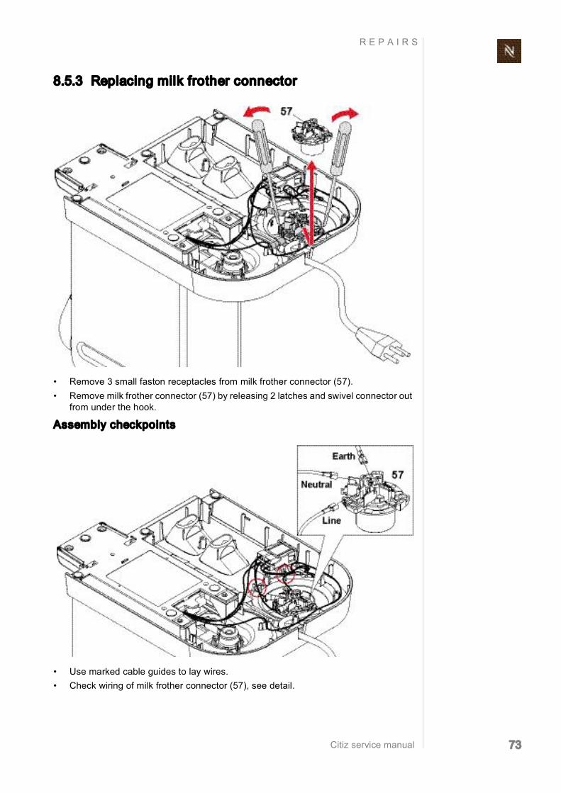
8.5.3 Replacing milk frother connector
• Remove 3 small faston receptacles from milk frother connector (57). • Remove milk frother connector (57) by releasing 2 latches and swivel connector out
from under the hook.
Assembly checkpoints
• Use marked cable guides to lay wires. • Check wiring of milk frother connector (57), see detail.

Citiz service manual 74
R E P A I R S
8.5.4 Replacing mains switch
• Remove 4 insulated faston receptacles from mains switch (54). • Press blade of screwdriver between holder of mains switch and platform carefully.
Lift holder with screwdriver slightly. Then press holder with mains switch (54) inwards till it can be removed.
Assembly checkpoints
• The mains switch holder (54) has a notch (see detail) to ensure a correct fitting posi tion.
• Use marked cable guides to lay wires. • Check wiring of mains switch (see "Wiring diagrams model Citiz & milk, EF 485/
486" on page 124 and following).
Use a pair of flat pli ers to pull off insulat ing sleeves with
receptacles.

Citiz service manual 75
R E P A I R S
8.5.5 Replacing power cord
• Remove 2 insulated faston receptacles (55) from mains switch (54).
• If present, disconnect ground wire (15, part of thermoblock assembly).
• Unlatch cable bracket (56) with screwdriver.
Use a pair of flat pli ers to pull off insulat ing sleeve with recep
tacle.
The counterpart, a flat receptacle, has a special connector
latching (see detail). Press down lever at first, then pull off receptacle.
The cable bracket is under tension. There fore, hold the cable
bracket with your finger when unlatching it.

Citiz service manual 76
R E P A I R S
Assembly checkpoints
• Use marked cable guides to lay wires. • Check wiring of power cord (see "Wiring diagrams model Citiz & milk, EF 485/486"
on page 124 and following).

Citiz service manual 77
R E P A I R S
8.5.6 Removing core unit Pay attention to the following safety advice before removing the core unit.
Danger of insulation damages (cuts) on wires between core unit and platform (phase and neutral wire, ground wire if existing).
The sharp casing edges of the platform (marked red in above illustra tion) can damage the insulation of wires.
Do not stretch and reciprocate wires over sharp edges while removing the core unit.

Citiz service manual 78
R E P A I R S
• Loosen 4 screws (41, oval shaped head) at the bottom side of platform.
For complete removal of the core unit proceed as follows:
• Remove bottom cover (refer to page 56). • Remove both insulated faston receptacles (15, part of thermoblock assembly) from
mains switch (54).
After this repair step the core unit can be pulled out of the plat
form slightly (with still con nected hoses and wires). Now the covers of the core unit can be removed.
Use a pair of flat pli ers to pull off insulat ing sleeve with recep
tacle.

Citiz service manual 79
R E P A I R S
• If present, disconnect ground wire (15, part of thermoblock assembly). • If the thermoblock or core unit has to be replaced, disconnect milk frother connector
(57). Otherwise the core unit can be removed together with this connector (see page 73).
• Remove water tank connector (53, see page 71).
Assembly checkpoints
• All covers are assembled on the core unit. • Check that wiring between core unit and platform is led through cable fixation (71). • Use marked cable guides to lay wires. • Check wiring of milk frother connector (57), see detail. • Check wiring of mains switch (54), see "Wiring diagrams model Citiz & milk,
EF 485/486" on page 124 and following. • During assembly of the water tank connector (53) on the platform, each of its 3
latches has to engage with an audible click.
The flat receptacle on the ground wire has a special connector
latching (see detail). Press down lever at first, then pull off receptacle.

Citiz service manual 80
R E P A I R S
8.6 Platform disassembly model Citiz & Co
8.6.1 General disassembly This general disassembly is necessary before the removal/disassembly of one or both core units is possible, gives access to the components and wiring of the platform.
• Take away all removable parts from platform and core units cup supports (8) with waste water containers (6) capsule containers (7) drip tray (48) with drip grid (49) water tank (44) with cover (45).

Citiz service manual 81
R E P A I R S
• At the bottom side of platform loosen 9 screws (41, oval shaped head). The core units are fastened with some of these screws as well.
Support both core units so that their remaining screw connection to the platform cannot be damaged.

Citiz service manual 82
R E P A I R S
• If necessary use a screwdriver to remove protective cover (51).

Citiz service manual 83
R E P A I R S
Assembly checkpoints
• Check if 2 rubber stoppers are mounted on each waste water container (6).
Risk of damage! While assembling the protective cover at the platform, take care not to jam any wires at the screw connections.

Citiz service manual 84
R E P A I R S
8.6.2 Replacing water tank connector
• Pull off both hoses (63, 64) from water tank connector (53). • Release the 3 latches one after the other by pressing the top of their hooks outwards
with a screwdriver (see detail) and lifting the water tank connector at the same time.
• Remove gasket (a) from water tank connector (53). • With the help of a pair of tweezers, remove clamping ring (b) and metal sieve (c). • Clean or replace parts.
The water tank con nector (53) is replaced together with gasket,
clamping ring and metal sieve.

Citiz service manual 85
R E P A I R S
Assembly checkpoints
• During assembly of the water tank connector (53) on the platform, each of its 3 latches has to engage with an audible click.
• Insert gasket correctly (see detail).
8.6.3 Replacing mains switch
• Remove 2 insulated faston receptacles from mains switch (54). • Press blade of screwdriver between holder of mains switch and platform carefully.
Lift holder with screwdriver slightly. Then press holder with mains switch (54) inwards till it can be removed.
Use a pair of flat pli ers to pull off insulat ing sleeves with
receptacles.

Citiz service manual 86
R E P A I R S
Assembly checkpoints
• Use marked cable guides to lay wires. • The mains switch holder (54) has a notch: correct fitting position is with mains switch
connections next to the platform (see detail).

Citiz service manual 87
R E P A I R S
8.6.4 Replacing power cord
• Remove insulated faston receptacle of phase wire (55) from mains switch (54). • Disconnect both insulated adapter plugs of neutral wire (55).
• If a ground wire is present, disconnect both flat receptacles (15).
• Unlatch cable bracket (56) with screwdriver.
Use a pair of flat pli ers to pull off insulat ing sleeve with recep tacle.
The flat receptacles of the ground wire connections (15)
have a special connector latching (see detail). Press down lever at first, then pull off receptacle.
The cable bracket is under tension. There fore, hold the cable
bracket with your finger when unlatching it.

Citiz service manual 88
R E P A I R S
Assembly checkpoints
• Use marked cable guides to lay wires. • Check wiring of power cord (see "Wiring diagrams model Citiz & Co, EF 487/488"
on page 128 and following).

Citiz service manual 89
R E P A I R S
8.6.5 Removing core units
• For each core unit loosen 1 remaining screw (41, oval shaped head) at the bottom side of platform.
For complete removal of a core unit proceed as follows: 4. Disconnect 2 insulated adapter plugs (15, phase and neutral wire). 5. If a ground wire (15, part of thermoblock) is present, disconnect flat receptacle. 6. Open protective case (69) with screwdriver and disconnect connection cable (b). 7. Pull out core unit from platform slightly to disconnect synchronization cable plug (a)
from electronic control board. 8. Pull off both hoses from angled Hconnector (65). 9. Lift core unit out of platform.
Both core units can be removed the same way.
After the first repair step the core unit can be pulled out of the
platform slightly (with still connected hoses and wires). Now the covers of the core unit can be removed.
The flat receptacle on the ground wire has a special connector
latching (see detail). Press down lever at first, then pull off receptacle.

Citiz service manual 90
R E P A I R S
Assembly checkpoints
• All covers are assembled on the core unit. • Use marked cable guides to lay wires. • Check wiring (see "Wiring diagrams model Citiz & Co, EF 487/488" on page 128
and following). • Make sure to reconnect synchronization cable plugs (a) on electronic control boards. • Mind the hose positions on angled Hconnector (65). • Check that wiring between core units and platform is led through cable fixations (71).

Citiz service manual 91
R E P A I R S
8.7 Disassembly of core unit, Crange
8.7.1 General disassembly The core unit has to be removed from the platform at first (see according chapter "plat form disassembly"). It is possible to perform a general disassembly of the core unit with intact hose and wire connections to the platform (e.g. for repair, leakage check).
Remove left side panel
1. Insert disassembly tool between bottom of left side panel (3) and chassis (1). 2. Swivel disassembly tool till latch opens at the bottom.
3. Insert disassembly tool into lower gap at the front. 4. Carefully turn disassembly tool slightly to the right to open the latch.
After general disas sembly of the core unit a repairing /
service holder device is helpful for further repair work.

Citiz service manual 92
R E P A I R S
5. Insert disassembly tool laterally into the gap above. 6. Carefully turn disassembly tool slightly forward to open the next latch. 7. Move disassembly tool upwards and open remaining latch the same way.
8. At the back insert disassembly tool into shadow gap of left side panel. 9. Swivel disassembly tool carefully to open first latch. 10. Move disassembly tool upwards and open the other two latches the same way.
Insert disassembly tool at right angles only. Otherwise the
shadow gap can be dam aged.
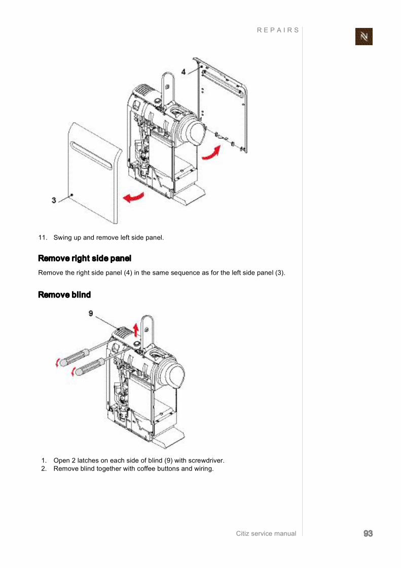
Citiz service manual 93
R E P A I R S
11. Swing up and remove left side panel.
Remove right side panel
Remove the right side panel (4) in the same sequence as for the left side panel (3).
Remove blind
1. Open 2 latches on each side of blind (9) with screwdriver. 2. Remove blind together with coffee buttons and wiring.

Citiz service manual 94
R E P A I R S
Remove cover
1. Use a screwdriver to release 2 latches on each side. 2. Lift and remove cover (2).
Remove front cover with outlet
1. Release 3 latches on front cover by hand and press out outlet (5, see detail).

Citiz service manual 95
R E P A I R S
Assembly checkpoints
• For easy identification, the side panels are marked with "RIGHT" or "LEFT" on the inside.
• Check if damper (10) for closing handle is installed on cover (2). • Check that all connection wires to the platform are led through cable fixation (71).

Citiz service manual 96
R E P A I R S
8.7.2 Replacing compact brewing unit
• Use a pair of pointed pliers to remove connector clip (34) and hose (29) with Oring (36).
• Use Torx screwdriver TX10 to loosen 4 screws (40). • After removal of compact brewing unit (14), release 2 latches with screwdriver and
remove steam cover (13).
Open closing handle to get access to hose connection.

Citiz service manual 97
R E P A I R S
Assembly checkpoints
• At first assemble steam cover (13) on new compact brewing unit (14) as shown. • Replace Oring (36) of hose connection on compact brewing unit.

Citiz service manual 98
R E P A I R S
8.7.3 Replacing pump
General
The pump (18) can only be replaced as assembly consisting of pump, prewired with thermostat (19, see below) or thermal cut off fuse (a) 2 pump supports (21, 22) pump cover (25).
A blown thermal cut off fuse (a) has to be replaced together with the pump assembly. A tripped thermostat (19) resets after about 30 min automatically.
The pump is equipped either with a thermal cut off fuse
or a thermostat depending on the voltage range or manufacturer.
a) Thermal cut off fuse 19) Thermostat with retaining clip
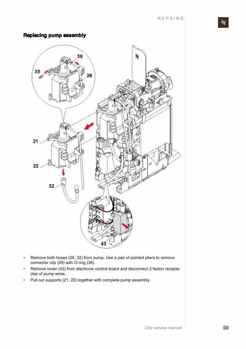
Citiz service manual 99
R E P A I R S
Replacing pump assembly
• Remove both hoses (28, 32) from pump. Use a pair of pointed pliers to remove connector clip (35) with Oring (36).
• Remove cover (43) from electronic control board and disconnect 2 faston recepta cles of pump wires.
• Pull out supports (21, 22) together with complete pump assembly.

Citiz service manual 100
R E P A I R S
Assembly checkpoints
• Adjust position of pump connector (23) towards hose (28) if necessary. • Check condition of supports (21, 22). Replace brittle supports.
• Pass hose (28) from pump to self priming device through lug on pump cover (25). • Use a cable clamp (a) to fix pump wires (different location depending on thermo
fuse/thermostat).
The white plastic Iid on the pump is rotata ble and has a square
seat for the fork wrench.

Citiz service manual 101
R E P A I R S
8.7.4 Replacing flow meter
Assembly checkpoint
• Lay connection cable to flow meter (27) in bracket. • Mind the hose positions on the flow meter.
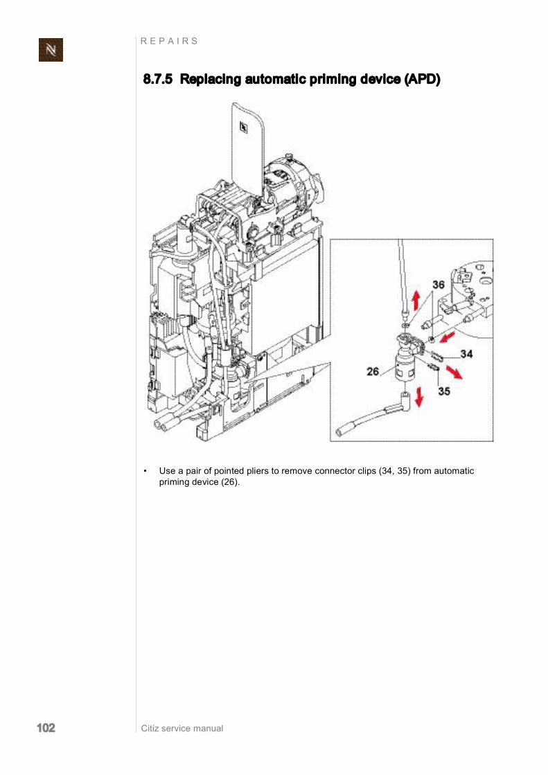
Citiz service manual 102
R E P A I R S
8.7.5 Replacing automatic priming device (APD)
• Use a pair of pointed pliers to remove connector clips (34, 35) from automatic priming device (26).
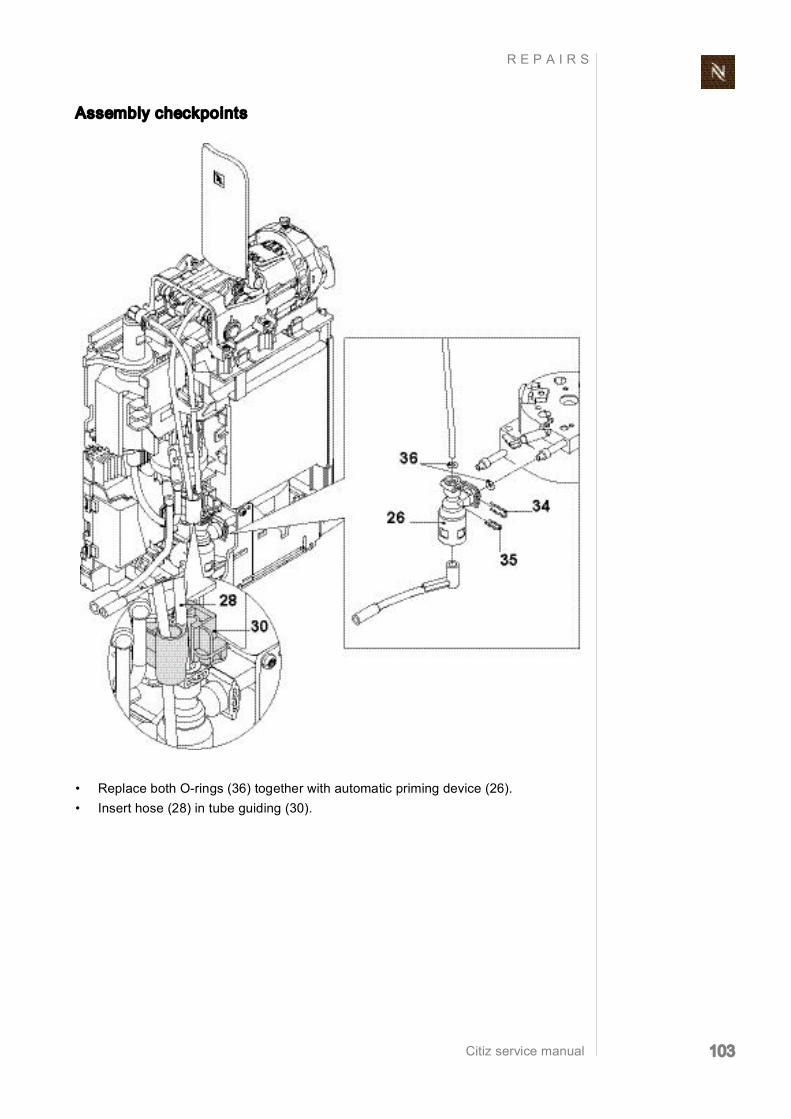
Citiz service manual 103
R E P A I R S
Assembly checkpoints
• Replace both Orings (36) together with automatic priming device (26). • Insert hose (28) in tube guiding (30).

Citiz service manual 104
R E P A I R S
8.7.6 Replacing thermoblock with NTC sensor and fine wire fuse(s)
A defect thermoblock can only be replaced with an assembly consisting of thermoblock, prewired with NTC temperature sensor, fine wire fuse(s) and ground
wire (only if required), thermoblock support.
• Use Torx screwdriver TX10 to loosen screw (40). • Release 3 latches and pull out support with thermoblock assembly (15).
Depending on national regulations, one or two fine wire
fuses are mounted on the thermoblock (see “Wiring diagrams” on page 118 and following).
Do not stress NTC cable when remov ing support.
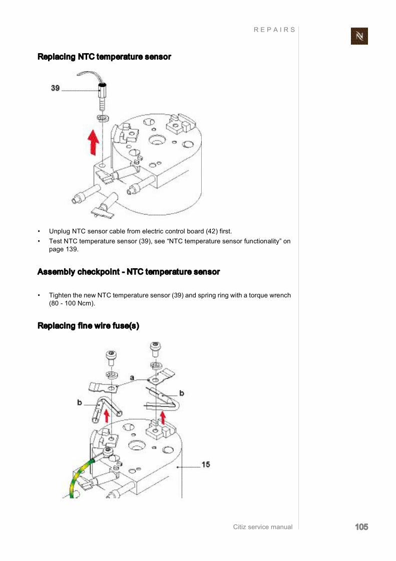
Citiz service manual 105
R E P A I R S
Replacing NTC temperature sensor
• Unplug NTC sensor cable from electric control board (42) first. • Test NTC temperature sensor (39), see “NTC temperature sensor functionality” on
page 139.
Assembly checkpoint NTC temperature sensor
• Tighten the new NTC temperature sensor (39) and spring ring with a torque wrench (80 100 Ncm).
Replacing fine wire fuse(s)

Citiz service manual 106
R E P A I R S
Assembly checkpoints fine wire fuse(s)
• When mounting a safety clip (a) on the thermoblock (15), make sure that the housing of the fine wire fuse (b) is positioned exactly below the safety clip.
• Tighten fastening screw and spring ring with a torque wrench (150 (+30/0) Ncm).
Assembly checkpoints thermoblock
• All wires from thermoblock to platform must be led through the bracket (a) at the bottom of the support.
• The black grommets (b) on the electrical thermoblock connections are slitted at the end. If an angled Faston receptacle (c) is used, make sure that its wire runs through this slit.
• Tighten central fastening screw (d) with a torque wrench (150 (+30/0) Ncm).

Citiz service manual 107
R E P A I R S
8.7.7 Replacing electronic control board with button prints
• Remove at first NTC connector from electronic control board, connector cable from flow meter, electronic lid (43), faston receptacles from electronic control board.
• Insert tip of screwdriver between chassis (1) and protective case of electronic control board (42) to release latches. Then pull out assembly.
The replacement board is equipped with protective hous
ing and cover.
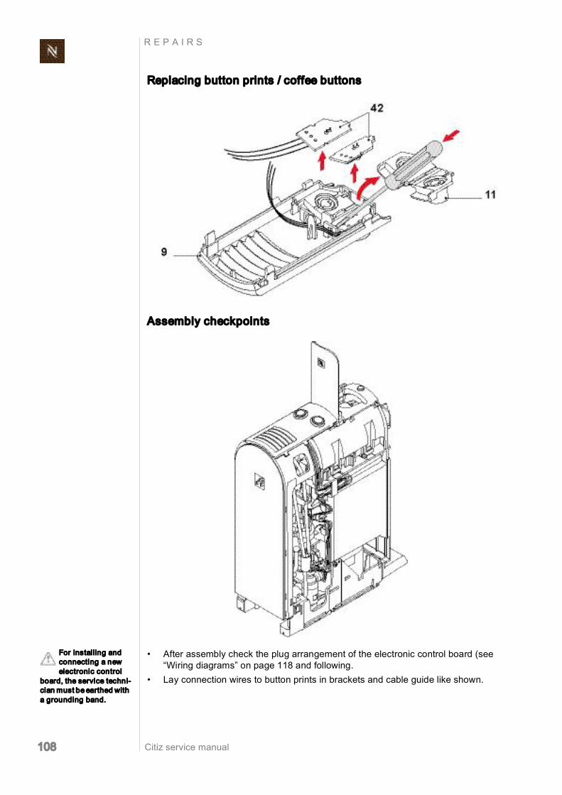
Citiz service manual 108
R E P A I R S
Replacing button prints / coffee buttons
Assembly checkpoints
• After assembly check the plug arrangement of the electronic control board (see “Wiring diagrams” on page 118 and following.
• Lay connection wires to button prints in brackets and cable guide like shown.
For installing and connecting a new electronic control
board, the service techni cian must be earthed with a grounding band.

Citiz service manual 109
R E P A I R S
8.8 Disassembly of core unit, Drange
8.8.1 General disassembly The core unit has to be removed from the platform at first (see according chapter "plat form disassembly"). It is possible to perform a general disassembly of the core unit with intact hose and wire connections to the platform (for repair, leakage check etc.).
Remove outlet
1. Open closing handle. 2. Press outlet (5) sidewards by hand carefully. 3. Insert disassembly tool into gap between outlet and right side panel (4).
After general disas sembly of the core unit a repairing/serv
ice holder device is helpful for further repair work.
The disassembly tool is necessary for removing outlet and
side panels undamaged.

Citiz service manual 110
R E P A I R S
4. Hold and pull outlet. 5. At the same time move disassembly tool upwards. 6. Carefully turn disassembly tool slightly backward to open the latch. 7. Insert disassembly tool into gap on the other side of the outlet. 8. Move disassembly tool upwards and carefully turn it slightly backward to open the
latch. 9. Remove outlet.
Remove right side panel
10. Insert disassembly tool between bottom of right side panel (4) and chassis. 11. Swivel disassembly tool till snap connection at the front opens. 12. Relocate disassembly tool and repeat procedure to open latch at the bottom of the
side panel.

Citiz service manual 111
R E P A I R S
13. Insert disassembly tool laterally into gap at the front. 14. Carefully turn disassembly tool slightly forward to open the first latch. 15. Move disassembly tool upwards and open the other two latches the same way.
16. At the back insert disassembly tool into shadow gap of right side panel. 17. Swivel disassembly tool carefully to open first latch. 18. Move disassembly tool upwards and repeat procedure for the other 2 latches.
Insert disassembly tool at right angles only. Otherwise the
shadow gap can be dam aged.
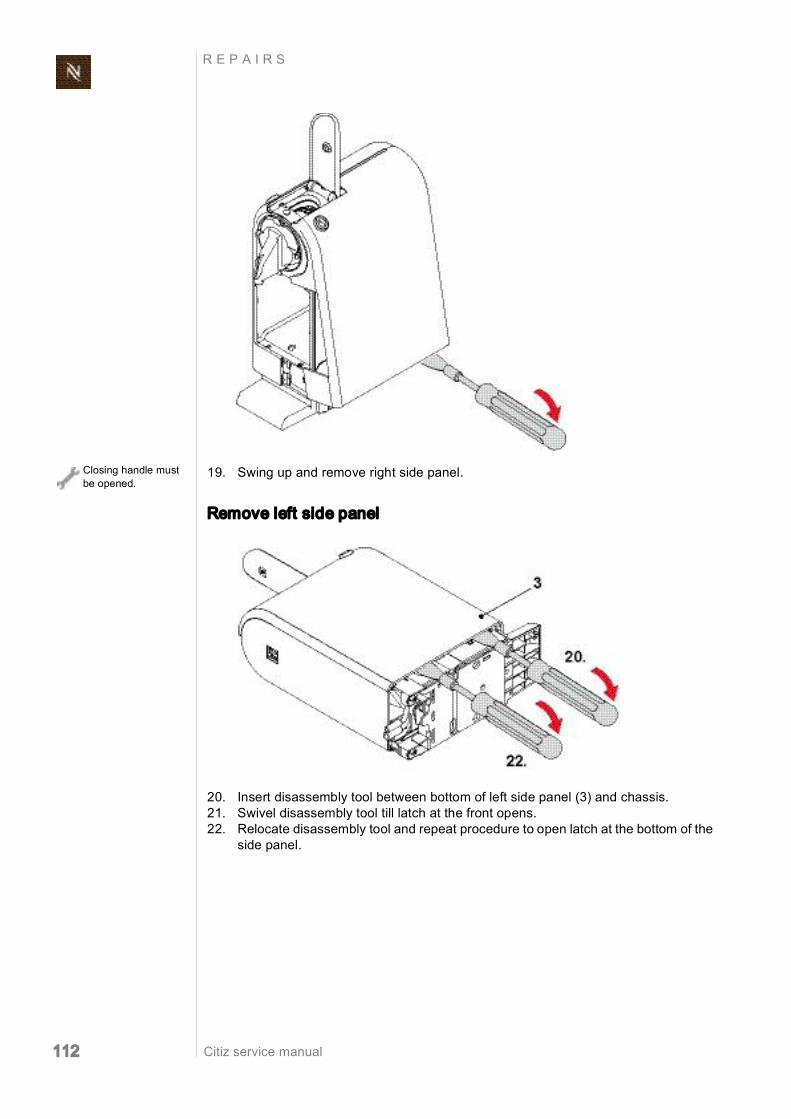
Citiz service manual 112
R E P A I R S
19. Swing up and remove right side panel.
Remove left side panel
20. Insert disassembly tool between bottom of left side panel (3) and chassis. 21. Swivel disassembly tool till latch at the front opens. 22. Relocate disassembly tool and repeat procedure to open latch at the bottom of the
side panel.
Closing handle must be opened.

Citiz service manual 113
R E P A I R S
23. Insert disassembly tool laterally into gap at the front. 24. Carefully turn disassembly tool slightly forward to open the first latch. 25. Move disassembly tool upwards and open the other two latches the same way.
26. At the back insert disassembly tool into shadow gap of left side panel. 27. Swivel disassembly tool carefully to open first latch. 28. Move disassembly tool upwards and repeat procedure for the other 2 latches.
Insert disassembly tool at right angles only. Otherwise the
shadow gap can be dam aged.

Citiz service manual 114
R E P A I R S
29. Swing up and remove left side panel.
Remove cover (2)
1. Remove both coffee buttons (11, 12) and prints (42) out of holder. 2. Remove wiring of coffee button prints from cable guides.
Closing handle should be opened.

Citiz service manual 115
R E P A I R S
3. Use a screwdriver to release 4 latches. 4. Open closing handle. 5. Lift and remove cover (2).
Assembly checkpoints
• Check if damper (10) for closing handle is installed on cover (2). • For correct layout of the wires to the coffee button prints, see “Replacing electronic
control board with button prints” on page 116. • Assemble left side panel (3) first. • Insert right side panel (4) into hinges at the top of the left side panel. Then fold down
right side panel and click latches. • Check that all latches are engaged.

Citiz service manual 116
R E P A I R S
8.8.2 Replacing electronic control board with button prints
• Refer to page 114 for removing cover (2). The replacement board (42) is equipped with protec
tive housing and cover.

Citiz service manual 117
R E P A I R S
• Remove first NTC connector from electronic control board, connector cable from flow meter, electronic lid (43), faston receptacles from electronic control board.
• Insert tip of screwdriver between chassis (1) and protective case of electronic control board (42) to release latches. Then pull out assembly.
Assembly checkpoints
• The left and right button prints (42) are marked with "L" or "R" for easy identification. • After assembly check the plug arrangement of the mainboard (see “Wiring
diagrams” on page 118 and following). • Lay connection wires to button prints in brackets and cable guides like shown.
For install ing and connecting a new electronic control
board, the service techni cian must be earthed with a grounding band.

Citiz service manual 118
R E P A I R S
8.9 Wiring diagrams
8.9.1 Wiring diagrams model Citiz
Wiring diagram 220 V 240 V IEC model Citiz, EF 483/484

Citiz service manual 119
R E P A I R S
Wiring diagram 120 V UL (USA/Canada) model Citiz, EF 483/484

Citiz service manual 120
R E P A I R S
Wiring diagram 120 V 127 V IEC (Brazil) model Citiz, EF 483/484

Citiz service manual 121
R E P A I R S
Wiring diagram 120 V 127 V IEC (Mexico) model Citiz, EF 483/484

Citiz service manual 122
R E P A I R S
Wiring diagram 110 V IEC (Taiwan) model Citiz, EF 483/484
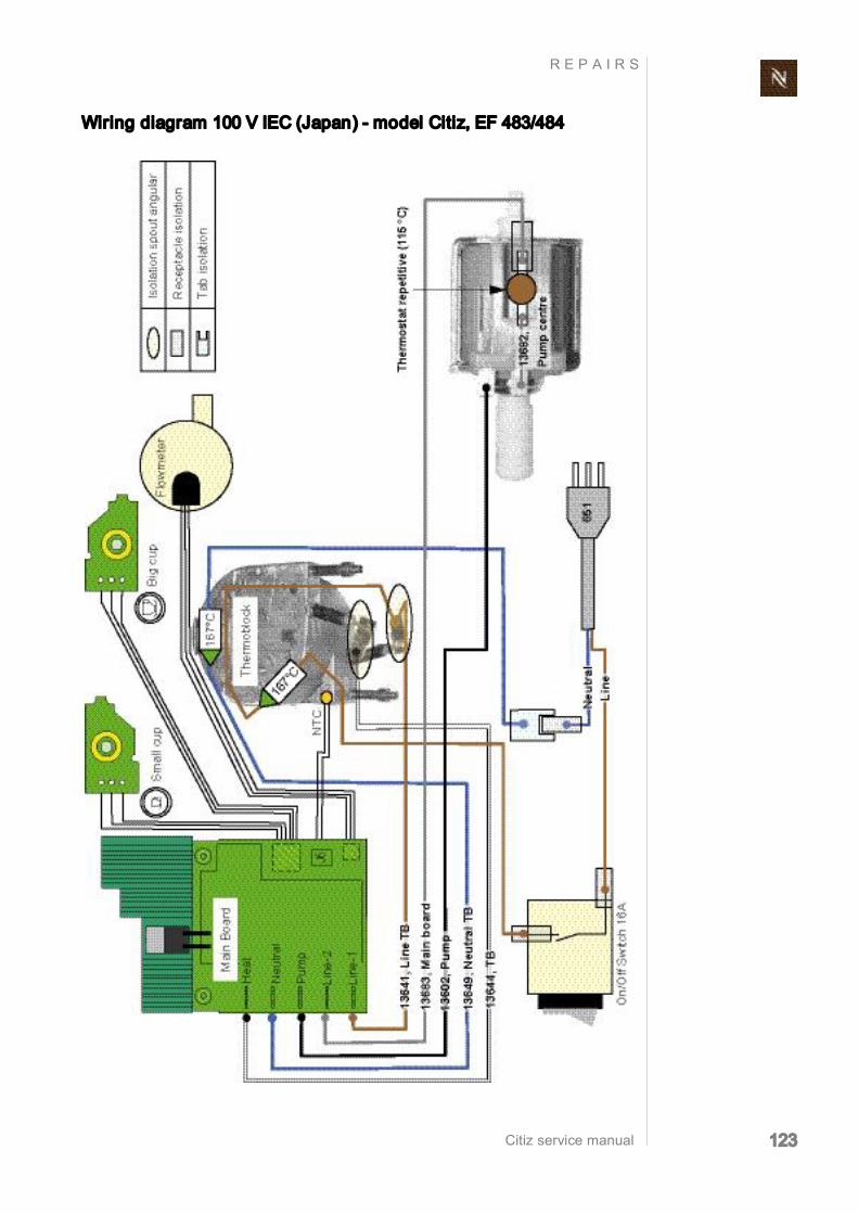
Citiz service manual 123
R E P A I R S
Wiring diagram 100 V IEC (Japan) model Citiz, EF 483/484

Citiz service manual 124
R E P A I R S
8.9.2 Wiring diagrams model Citiz & milk, EF 485/486
Wiring diagram 220 V 240 V IEC model Citiz & milk, EF 485/486

Citiz service manual 125
R E P A I R S
Wiring diagram 120 V UL (USA/Canada) model Citiz & milk, EF 485/ 486

Citiz service manual 126
R E P A I R S
Wiring diagram 120 V 127 V IEC (Brazil) model Citiz & milk, EF 485/ 486

Citiz service manual 127
R E P A I R S
Wiring diagram 120 V 127 V IEC (Mexico) model Citiz & milk, EF 485/486

Citiz service manual 128
R E P A I R S
8.9.3 Wiring diagrams model Citiz & Co, EF 487/488
Wiring diagram 220 V 240 V IEC core unit, model Citiz & Co, EF 487/488

Citiz service manual 129
R E P A I R S
Wiring diagram 220 V 240 V IEC model Citiz & Co, EF 487/488

Citiz service manual 130
F U N C T I O N T E S T S
9 F UNC T I ON T E S T S
9.1 Safety instructions Some function tests are performed with an energized, partly opened coffee machine.
9.2 Required equipment
9.2.1 Overview
To simplify matters, the model Citiz with core unit "Crange" is
used to exemplify through out this chapter.
Danger of electrocution! Mains voltage inside the coffee machine. Do not touch any live part while performing tests.
Danger of burns! Hot parts and water under pressure inside the coffee machine. Do not touch any hot parts while checking for leakages! Always wear protective goggles.
Symbolic illustration of function test equip ment.
1) Pressure gauge (EFR no. 16195)
2) Citiz pressure gauge adapter 3) Digital multimeter
(for NTC temperature sensor test)
4) Electronic thermometer (or digital multimeter suitable for temper ature measurement)
5) Timer 6) Measuring beaker 7) Test equipment for protective earth con
tinuity test and protective insulation test

Citiz service manual 131
F U N C T I O N T E S T S
9.2.2 Citiz pressure gauge adapter
This pressure gauge adapter is designed for the Citiz coffee machines.
The pressure gauge adapter has 2 parts: • A connecting unit (3) with a sealing cone that is inserted in the capsule cage of the
brewing unit. • A hand actuated fixation unit (4) to lock and seal the complete pressure gauge
adapter in the brewing unit.
1) Quick action coupling for pressure hose
2) Operating lever
3) Connecting unit 4) Fixation unit
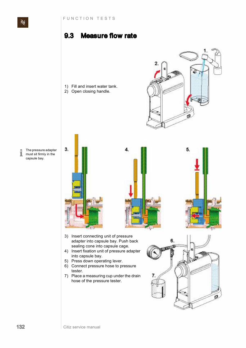
Citiz service manual 132
F U N C T I O N T E S T S
9.3 Measure flow rate
The pressure adapter must sit firmly in the capsule bay.
1) Fill and insert water tank. 2) Open closing handle.
3) Insert connecting unit of pressure adapter into capsule bay. Push back sealing cone into capsule cage.
4) Insert fixation unit of pressure adapter into capsule bay.
5) Press down operating lever. 6) Connect pressure hose to pressure
tester. 7) Place a measuring cup under the drain
hose of the pressure tester.
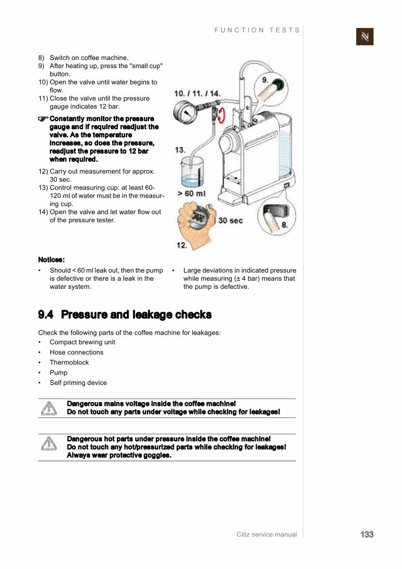
Citiz service manual 133
F U N C T I O N T E S T S
9.4 Pressure and leakage checks Check the following parts of the coffee machine for leakages: • Compact brewing unit • Hose connections • Thermoblock • Pump • Self priming device
8) Switch on coffee machine. 9) After heating up, press the "small cup"
button. 10) Open the valve until water begins to
flow. 11) Close the valve until the pressure
gauge indicates 12 bar.
Constantly monitor the pressure gauge and if required readjust the valve. As the temperature increases, so does the pressure, readjust the pressure to 12 bar when required.
12) Carry out measurement for approx. 30 sec.
13) Control measuring cup: at least 60 120 ml of water must be in the measur ing cup.
14) Open the valve and let water flow out of the pressure tester.
Notices: • Should < 60 ml leak out, then the pump
is defective or there is a leak in the water system.
• Large deviations in indicated pressure while measuring (± 4 bar) means that the pump is defective.
Dangerous mains voltage inside the coffee machine! Do not touch any parts under voltage while checking for leakages!
Dangerous hot parts under pressure inside the coffee machine! Do not touch any hot/pressurized parts while checking for leakages! Always wear protective goggles.

Citiz service manual 134
F U N C T I O N T E S T S
9.4.1 Preparations Depending on core unit range, refer to "Disassembly of core
unit, Crange" on page 91 or "Disassembly of core unit, Drange" on page 109.
The pressure adapter must sit firmly in the capsule bay.
1) Remove left side panel of core unit. 2) Insert core unit back into platform. 3) Fill and insert water tank.
4) Insert connecting unit of pressure adapter into capsule bay. Push back sealing cone into capsule cage.
5) Insert fixation unit of pressure adapter into capsule bay.
6) Press down operating lever. 7) Connect pressure hose to pressure
tester. 8) Place a measuring cup under the drain
hose of the pressure tester.

Citiz service manual 135
F U N C T I O N T E S T S
9.4.2 Test run
9) Connect mains cable. 10) Switch on coffee machine.
11) After heating up, press the "small cup" button.
12) Open the valve and let the water flow for approximately 10 sec out of the drain hose.
13) Close the valve completely. The pres sure stabilizes after increasing briefly between 1619 bar (pressure check).
The pressure increases slowly with increasing temperature. Should the pressure exceed 23 bar, switch off the coffee machine and release the pressure by opening the valve.
For better visibility use a flashlight.
14) Check all connections under pressure for audible and visible leaks.
Do not run the pump for more than 50 sec with the valve closed.

Citiz service manual 136
F U N C T I O N T E S T S
9.5 Measure coffee temperature
15) Switch off the coffee machine. 16) Open the valve and let water flow out
of the pressure tester.
1) Switch on coffee machine. 2) Place a measuring cup on cup sup
port.
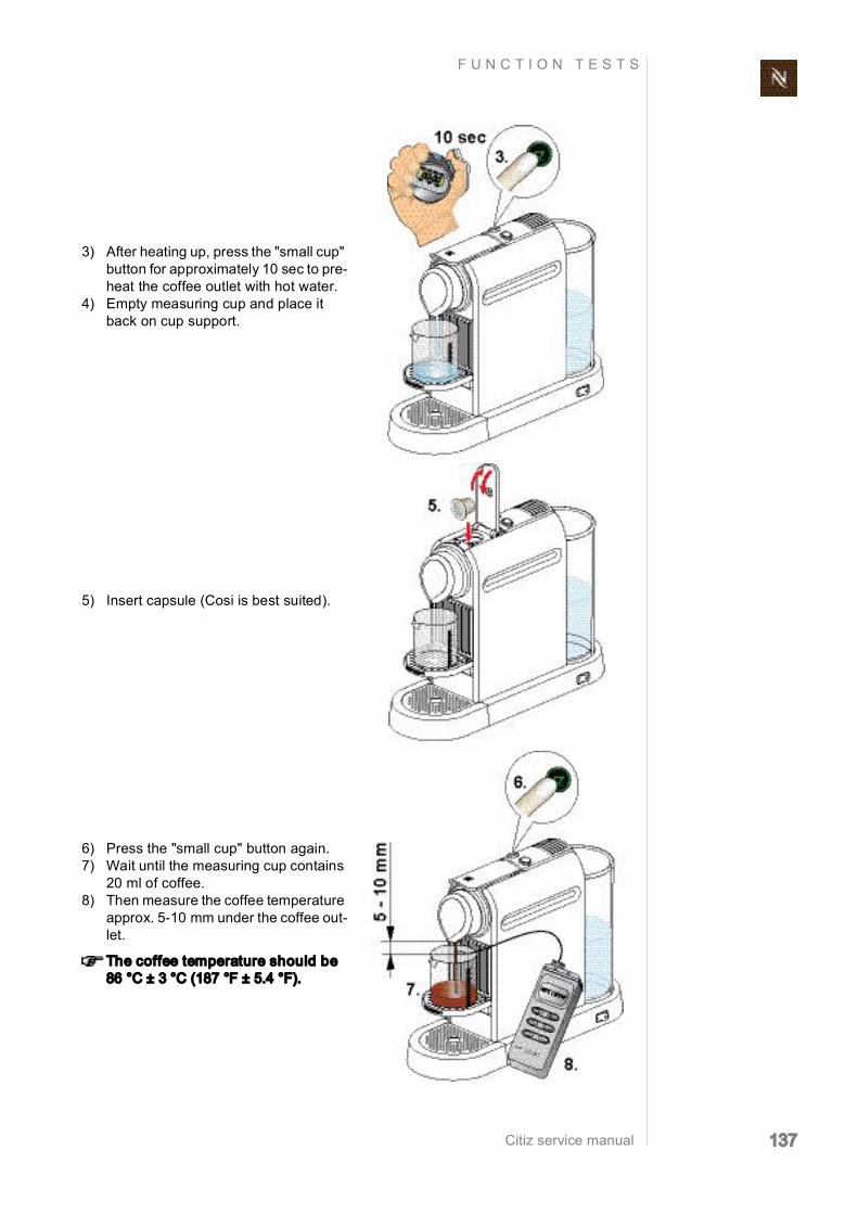
Citiz service manual 137
F U N C T I O N T E S T S
3) After heating up, press the "small cup" button for approximately 10 sec to pre heat the coffee outlet with hot water.
4) Empty measuring cup and place it back on cup support.
5) Insert capsule (Cosi is best suited).
6) Press the "small cup" button again. 7) Wait until the measuring cup contains
20 ml of coffee. 8) Then measure the coffee temperature
approx. 510 mm under the coffee out let.
The coffee temperature should be 86 °C ± 3 °C (187 °F ± 5.4 °F).

Citiz service manual 138
F U N C T I O N T E S T S
9.6 Milk frother tests
Prerequisite
Use newly opened UHT, full fat or semiskimmed milk at fridge temperature (+ 8 °C till + 10 °C) for the following tests only.
9.6.1 Measure hot milk temperature
• Prepare 240 ml hot milk in milk frother (use mixer without spring). • Measure temperature immediately after preparation in jug.
The milk temperature should be between + 60 °C and + 70 °C (140 °F till 158 °F).
9.6.2 Measure milk froth ratio
• Prepare cold milk froth out of 120 ml milk in milk frother (use whisk with spring). • Empty content of milk frother into measuring beaker. • Determine the ratio x [%] of milk froth to liquid milk with following formula:
Approximate values: direct after preparation .....................................................................................x = 250 60 sec after preparation ....................................................................................x = 190
The disregard of this specification can affect the measuring
results.
Spattered milk may cause burns. Only use milk frother
with lid.
x H2 H1 H1
100 × =

Citiz service manual 139
F U N C T I O N T E S T S
9.7 NTC temperature sensor functionality The resistance of the NTC temperature sensor must be within a defined range, other wise the temperature regulation will not work properly and the coffee machine will stay/ go into failure mode.
An easy way to check the functionality of the NTC temperature sensor is to measure the ohmic resistance at ambient temperature. With this measurement, most defect NTC temperature sensors can be detected.
Avoid contamination of sensor contact sur face during handling.
1) Unplug NTC temperature sensor from electronic control board.
2) Remove NTC temperature sensor from thermoblock (refer to page 104 and following).
3) Measure temperature of sensor body (do not touch either temperature or NTC sensor by hand).
4) Measure resistance of NTC tempera ture sensor by connecting a multime ter at the plug.
5) Compare measuring values with fol lowing diagram or table.

Citiz service manual 140
F U N C T I O N T E S T S
NTC Diagram
NTC temperature sensor, R/T characteristics
Graph 1 ........................................................................................max. resistance value Graph 2 .........................................................................................min. resistance value
Measurement table
NTC temperature [°C]
NTC temperature [°F]
NTC min. resistance [kOhm]
NTC max. resistance [kOhm]
15 59 155.63 168.48 20 68 122.41 131.23 25 77 97.00 103.00 30 86 76.63 82.12 35 95 60.90 65.86

Citiz service manual 141
F U N C T I O N T E S T S
9.8 Protective earth (PE) continuity test
9.8.1 What coffee machine has to be tested and when? This test is only necessary for class 1 equipment (threewire power cord with protective earth) for models Citiz & milk, EF 485/486 after a repair whenever a general disassembly of the platform and/or core unit was
performed.
9.8.2 General
Legal regulation
In case of a repair/modification of the coffee machine, the repair centre is bound by law to protect the user/consumer by restoring the regular condition of the appliance and performing the respective tests according to EN/IEC 603351 “Safety of household
and similar electrical appliances” and national regulations (e.g. DIN VDE 0701).
Description
Protective earth continuity measurements are made between the protective earth terminal and conductive, touchable parts of the coffee machine where dangerous voltage could occur if the basic insulation was to fail.
This test assures that the ground (earth) connection does not have an interruption between the plug and
touchable, conductive housing parts the permissible ground resistance of those conductive, touchable parts is less than
0.3 Ohms (with a test current of 200 mA DC).
Test equipment
Special test equipment is needed that complies with the regulations to perform protec tive earth continuity measurements. Detailed requirements and tolerances must be veri fied by your local authorities or measurement supplier in any case.
Test report
For legal reasons a repair or test report should be prepared and filed with following infor mation customer (name, address) type and serial number of coffee machine date of repair/test(s) performed test(s)/measuring value(s) used test equipment signature
Ask Nespresso for recommendations about test equipment.

Citiz service manual 142
F U N C T I O N T E S T S
9.8.3 Test sequence
This test sequence is not applicable for cof fee machines with
twowire power cords (with out ground pin).
Danger of electrocution! Do not plug in the coffee machine during the protective earth continuity test. Read and observe safety instructions in user manual of test equipment.
1) Connect black measuring cable to ground pin of power plug with an alli gator clip (example shown: Swiss power plug).
Symbolic illustration of test equipment.
2) Switch on test equipment and select protective earth continuity test.
The coffee machine Citiz & Co has 2 test holes to check both
thermoblocks.
Test holes on bottom of Citiz / Citiz & milk / Citiz & Co platforms
3) Insert tip of red test probe in test hole and touch thermoblock.
4) Press "measure" button and read off displayed resistance.
The resistance must be lower than 0.3 Ohm.
5) Fill in measured value(s) in a test report.

Citiz service manual 143
F U N C T I O N T E S T S
9.8.4 What to do if the protective earth continuity test fails • Check/measure ground connection in platform (refer to page 75). • Check/measure ground connection on milk frother connector (refer to page 73 and
page 124 for wiring diagram). Replace milk frother connector if necessary. • Clean ground contact on milk frother. Measure resistance between ground contact
and jug of milk frother. Replace milk frother if necessary.
Do not damage inside coating of milk frother jug with
the probe tip.
Additional test for coffee machine Citiz & milk:
1) Touch upper metallic part of milk frother with red test probe.
2) Press "measure" button and read off displayed resistance.
3) Repeat measurement on another metallic spot of milk frother for verifica tion.
The resistance must be lower than 0.3 Ohm.
4) Fill in measured value(s) in a test report.

Citiz service manual 144
F U N C T I O N T E S T S
9.9 Protective insulation test
9.9.1 What coffee machines have to be tested and when? This test is necessary for class 1 and 2 equipment (with/without protective earth) after a repair whenever a general disassembly of the platform and/or core unit was
performed.
9.9.2 General
Legal regulation
In case of a repair/modification of the coffee machine, the repair centre is bound by law to protect the user/consumer by restoring the regular condition of the appliance and performing the respective tests according to EN/IEC 603351 “Safety of household
and similar electrical appliances” and national regulations (e.g. DIN VDE 0701).
Description
The insulation test assures that wiring and insulation of the coffee machine fullfill the normative require
ments after a repair, rates the insulation capability of the coffee machine, is a very dangerous test because of a high test voltage (500 V DC).
For the insulation test, phase and neutral wire are shunted at the power plug. Then a test voltage is applied between phase/neutral and selected parts of the coffee machine.
Test equipment
Special test equipment is needed that complies with the regulations to perform insula tion and withstanding voltage tests. Detailed requirements and tolerances must be veri fied with your local authorities or measurement supplier in any case.
Ideally the test equipment has a national power socket for testing, so that the coffee machine can plugged in directly. Otherwise a special shunt is necessary to connect the phase and neutral pin of the coffee machine’s power plug.
Test report
For legal reasons a repair or test report should be prepared and filed with following infor mation customer (name, address) type and serial number of coffee machine date of repair/test(s) performed test(s)/measuring value(s), test points used test equipment signature
Ask Nespresso for recommendations about test equipment.

Citiz service manual 145
F U N C T I O N T E S T S
9.9.3 Test sequence
Danger of electrical shock/short circuit! Do not plug in the coffee machine during insulation test.
Danger of electrical shock! Do not touch tip of test probes. Do not touch metallic parts of coffee machine during test. Read and observe safety instructions in user manual of test equipment.
A Swiss power plug is shown here as an example.
Use a short circuit plug or special alliga tor clips etc. as sub
stitute for this test adapter.
1) Connect the phase and neutral pin of the power plug together with a test adapter (procured by the repair centre).
2) Connect the black measuring cable to the test adapter (see image).
3) Turn the ONOFF machine's main switch on position I (ON).
Symbolic illustration of test equipment.
4) Switch on test equipment and select an insulation test voltage of 500 V DC.
Some test equipment displays test passed or failed instead of
the insulation resistance.
5) Touch closing handle with red test probe.
6) Press "measure" button. 7) Read off displayed insulation resist
ance or test result.
The insulation resistance must be higher than 300 kOhm (300,000 Ohm).

Citiz service manual 146
F U N C T I O N T E S T S
The coffee machine Citiz & Co has 2 test holes to check both
thermoblocks.
Test holes on bottom of Citiz / Citiz & milk / Citiz & Co platforms
8) Insert tip of red test probe in test hole and touch thermoblock.
9) Press "measure" button. 10) Read off displayed insulation resist
ance or test result.
The insulation resistance must be higher than 300 kOhm (300’000 Ohm).
11) Switch off test equipment. 12) Short red with black test probe to
make sure that test voltage is dis charged.
13) Fill in results in a test report.
Additional tests for coffee machine Citiz & milk:
1) Touch upper metallic part of milk frother with red test probe.
2) Press "measure" button. 3) Read off displayed insulation resist
ance or test result.

Citiz service manual 147
F U N C T I O N T E S T S
9.9.4 What to do if the insulation test fails
• Assume that the coffee machine is defect after a failed insulation test. • Check wiring and locate fault. After fault clearance proceed with troubleshooting
check list (see page 49). • In case of doubt an insultation test on the milk frother alone can be carried out on
the coffee machine Citiz & milk: touch phase and neutral contacts at the bottom with one test probe successively and the metallic upper part with the other test probe. If insulation test fails, replace milk frother.
4) Remove milk frother from platform. 5) Insert red test probe in central opening
of milk frother connector (ground con nection).
6) Press "measure" button. 7) Read off displayed insulation resist
ance or test result. 8) Switch off test equipment. 9) Short red with black test probe to
make sure that test voltage is dis charged.
10) Fill in result in test report.
Risk of damage! A sparkover can damage the electronic control board and sensors etc.

Citiz service manual 148
E X P L O S I O N D R A W I N G S
1 0 E X P L O S I ON DRA W I NGS
10.1Model Citiz, core unit Drange (EF 483)

Citiz service manual 149
E X P L O S I O N D R A W I N G S
10.2 Model Citiz, core unit Crange (EF 484)

Citiz service manual 150
E X P L O S I O N D R A W I N G S
10.3 Model Citiz & milk, core unit Drange (EF 485)

Citiz service manual 151
E X P L O S I O N D R A W I N G S
10.4 Model Citiz & milk, core unit Crange (EF 486)

Citiz service manual 152
E X P L O S I O N D R A W I N G S
10.5 Model Citiz & Co, core unit Drange (EF 487)

Citiz service manual 153
E X P L O S I O N D R A W I N G S
10.6 Model Citiz & Co, core unit Crange (EF 488)

Citiz service manual 154
P A R T S L I S T
1 1 P A R T S L I S T
Pos. Component Remark
1 Chassis A 1 Chassis B 2 Cover A 2 Cover B 3 Side panel A left Ivory (old: Creamy White) 4 Side panel A right Ivory (old: Creamy White) 3 Side panel A left Black (old: Piano Black) 4 Side panel A right Black (old: Piano Black) 3 Side panel B left Grey (Slate) 4 Side panel B right Grey (Slate) 3 Side panel B left Red (old: Retro Red) 4 Side panel B right Red (old: Retro Red)
5 Outlet B spare, containing Front Cover (1x) Outlet B chrome (1x)
5 Outlet A Chrome
6 Waste water spare, containing Waste water A+B (1x) Cup support stop (2x)
7 Capsule Container A+B 8 Cup support A 8 Cup support B 9 Blind 10 Damper MBU closing handle 11 Espresso Button A 12 Coffee Button A 11 Coffee Button B 13 Steam Cover 14 TMBU Handle A 14 TMBU Handle B
15 Thermobloc 230 V Complete assembly incl. support, complete wiring (safety), with NTC
15 Thermobloc 120 V (USA) Complete assembly incl. support, complete wiring (safety), with NTC
15 Thermobloc 120 V (Brasilien/Taiwan) Complete assembly incl. support, complete wiring (safety), with NTC
15 Thermobloc 120 V (Mexico) Complete assembly incl. support, complete wiring (safety), with NTC
15 Thermobloc 230 V Complete assembly incl. support, complete wiring (safety), with NTC
15 Thermobloc 120 V (USA) Complete assembly incl. support, complete wiring (safety), with NTC
15 Thermobloc 120 V (Brasilien/Mexico) Complete assembly incl. support, complete wiring (safety), with NTC
15 Thermobloc 100 V Complete assembly incl. support, complete wiring (safety), with NTC
15 Thermobloc 230 V Complete assembly incl. support, complete wiring (safety), with NTC

Citiz service manual 155
P A R T S L I S T
15 Thermobloc 230 V Complete assembly incl. support, complete wiring (safety), with NTC
18 Pump 230 V Incl. thermostat and both wires, pump cover, pump sup ports, 90° angle. Invensys, no Ceme, no Sysko
18 Pump 120 V Incl. thermostat and both wires, pump cover, pump sup ports, 90° angle. Invensys, no Ceme, no Sysko
18 Pump 100 V Incl. thermostat and both wires, pump cover, pump sup ports, 90° angle. Invensys, no Ceme, no Sysko
18 Pump 127 V IEC Incl. thermostat and both wires, pump cover, pump sup ports, 90° angle. Invensys, no Ceme, no Sysko
19 Thermostat 20 Clip Thermostat 21 Pump support upside 22 Pump support downside 23 Pump connector 90° 24 Oring 5, 28 x 1, 78 25 Pump cover 26 APD Complete 27 Flowmeter FHKSC12 4.524VDC, 513mA (Birdy FS: 5.6V, 45mA) new standard 28 Hose Pump APD Delivery without orings (you can loose them) 29 Hose TB TMBU Delivery without orings (you can loose them) 30 Tube guiding 31 Angle hose FM in 32 Angle hose FM Pump 33 Angle hose APD out 33 Angle hose APD out M4 34 Connector clip 5mm 35 Connector clip 4mm 36 Oring 3.40 x 1.90 37 Hose connector 55° Also part of TB spare assembly 38 Isolation spout angular Also part of TB spare assembly 39 NTC (Cable length =160 mm) 40 PT Screw Torx K30 x 12 41 PT Screw Oval K30 x 12 42 Electronic Control Board M1+3 220240 V 50/60 Hz Incl. housing 42 Electronic Control Board M1+3 120127 V 50/60 Hz Incl. housing 42 Electronic Control Board M1+3 100110 V 50/60 Hz Incl. housing 42 Electronic Control Board M4 220240 V 50/60 Hz Incl. housing 43 Electronic lid 44 Water tank 1 44 Water tank 4 45 Water tank 1 cover 45 Water tank 4 cover 46 Drip tray 1 Nespresso (inc.rubber feet) 46 Drip tray 1 Krups (incl. rubber feet) 46 Drip tray 1 Turmix (incl. rubber feet) 46 Drip tray 1 DeLonghi (incl. rubber feet) 46 Drip tray 1 Magimix (incl. rubber feet) 46 Drip tray 1 Koenig (incl. rubber feet) 47 Rubber feet (Drip tray 1) 48 Drip tray 3 48 Drip tray 4
Pos. Component Remark

Citiz service manual 156
P A R T S L I S T
49 Drip Grid A 1 49 Drip Grid B 1 49 Drip grid A 3 49 Drip grid B 3 49 Drip grid A 4 49 Drip grid B 4 50 Base plate 1 top Inc. rubber feet 50 Base plate 3 top Inc. rubber feet 50 Base plate 4 top Inc. rubber feet 51 Base plate 1 bottom Inc. rubber feet 51 Base plate 3 bottom Inc. rubber feet 51 Base plate 4 bottom Inc. rubber feet 52 Rubber feet 53 Water tank connector 1 Incl. filter & seal 53 Water tank connector 4 Incl. filter & seal 54 ON/OFF switch incl. support (spare parts) 2pol 54 ON/OFF switch incl. support (spare parts) 1pol new marquardt 55 Power supply cord JP 2pol Incl. receptacle and isolation 55 Connection cable UL 1 Incl. receptacle and isolation 55 Connection cable 230 V country spec. M1 (SEV) Incl. receptacle and isolation 55 Connection cable 230 V country spec. M1 (AU) Incl. receptacle and isolation 55 Connection cable 230 V country spec. M1 (IL) Incl. receptacle and isolation 55 Connection cable 230 V country spec. M1 (UK) Incl. receptacle and isolation 55 Connection cable 230 V country spec. M1 (Cebec) Incl. receptacle and isolation 55 Connection cable 230 V country spec. M1 (AR) Incl. receptacle and isolation 55 Connection cable 230 V country spec. M1 (KR) Incl. receptacle and isolation 55 Connection cable 230 V country spec. M1 (ZA 220 V) Incl. receptacle and isolation 55 Connection cable 230 V country spec. M1 (CN) Incl. receptacle and isolation 55 Connection cable 230 V country spec. M1 (SG) Incl. receptacle and isolation 55 Power supply cord TW 3pol Incl. receptacle and isolation 55 Connection cable 230 V country spec. M1 (BR 220 V) Incl. receptacle and isolation 55 Power supply cord BR 3pol Incl. receptacle and isolation 55 Power supply cord BR 3pol Incl. receptacle and isolation 55 Connection cable UL M3 country spec Incl. receptacle and isolation 55 Connection cable UL US/MX M3 Incl. receptacle and isolation 55 Connection cable 230 V country spec. M3 (ZA) Incl. receptacle and isolation 55 Connection cable 230 V country spec. M3 (BR 220 V) Incl. receptacle and isolation 55 Connection cable 230 V country spec. M3 (UK) Incl. receptacle and isolation 55 Connection cable 230 V country spec. M3 (AR) Incl. receptacle and isolation 55 Connection cable 230 V country spec. M3 (AU) Incl. receptacle and isolation 55 Connection cable 230 V country spec. M3 (SEV) Incl. receptacle and isolation 55 Connection cable 230 V country spec. M3 (CN) Incl. receptacle and isolation 55 Connection cable 230 V country spec. M3 (Cebec) Incl. receptacle and isolation 55 Connection cable 230 V country spec. M3 (IL) Incl. receptacle and isolation 55 Connection cable 230 V country spec. M3 (KR) Incl. receptacle and isolation 55 Connection cable 230 V country spec. M3 (SG) Incl. receptacle and isolation 55 Connection cable 230 V country spec. M4 (SEV) Incl. receptacle and isolation 55 Connection cable 230 V country spec. M4 (Cebec) Incl. receptacle and isolation 55 Connection cable 230 V country spec. M4 (UK) Incl. receptacle and isolation 55 Connection cable 230 V country spec. M4 (AU) Incl. receptacle and isolation 55 Connection cable 230 V country spec. M4 (IL) Incl. receptacle and isolation 55 Connection cable 230 V country spec. M4 (AR) Incl. receptacle and isolation
Pos. Component Remark

Citiz service manual 157
P A R T S L I S T
55 Connection cable 230 V country spec. M4 (SG) Incl. receptacle and isolation 55 Connection cable 230 V country spec. M4 (ZA) Incl. receptacle and isolation 55 Connection cable 230 V country spec. M4 (BR220 V) Incl. receptacle and isolation 55 Connection cable 230 V country spec. M4 (CN) Incl. receptacle and isolation 56 Cable bracket UL 2pol 56 Cable bracket UL 3pol 56 Cable bracket IEC 3pol 57 Otter connector CS7 58 Cup storage 59 Aeroccino 3 220240 V 50/60 Hz 59 Aeroccino 3 120127 V 50/60 Hz 60 Mixer (hot milk) 61 Whisk (foam) 62 Aeroccino Lid incl. seal 63 Angle hose water 4 64 Angle hose venting 4 65 Angle hard double M4 66 Tank snap hook 69 Connection isolation 70 Double Tab 4.8Sn 71 Cable fixation TB 72 Cover stopper
Pos. Component Remark

Citiz service manual 158
N O T E S
1 2 NO TE S


