
Service ManualTrucks
Group 260–600
Cooling System
D12, D12A, D12B, D12C
PV776-TSP142854

Foreword
The descriptions and service procedures contained in this manual are based on de-signs and methods studies carried out up to August 2000.
The products are under continuous development. Vehicles and components producedafter the above date may therefore have different specifications and repair methods.When this is believed to have a significant bearing on this manual, supplementary ser-vice bulletins will be issued to cover the changes.
The new edition of this manual will update the changes.
In service procedures where the title incorporates an operation number, this is a refer-ence to an S.R.T. (Standard Repair Time).
Service procedures which do not include an operation number in the title are for gen-eral information and no reference is made to an S.R.T.
The following levels of observations, cautions and warnings are used in this ServiceDocumentation:
Note: Indicates a procedure, practice, or condition that must be followed in order tohave the vehicle or component function in the manner intended.
Caution: Indicates an unsafe practice where damage to the product could occur.
Warning: Indicates an unsafe practice where personal injury or severe damage to theproduct could occur.
Danger: Indicates an unsafe practice where serious personal injury or death could oc-cur.
Volvo Trucks North America, Inc.Greensboro, NC USA
Order number: PV776-TSP142854
© 2000 Volvo Trucks North America, Inc., Greensboro, NC USA
All rights reserved. No part of this publication may be reproduced, stored inretrieval system, or transmitted in any forms by any means, electronic, me-chanical, photocopying, recording or otherwise, without the prior writtenpermission of Volvo Trucks North America, Inc..

ContentsGeneral .................................................................................................... 3
Tools ........................................................................................................ 5Special Tools ......................................................................................... 5Special Equipment ................................................................................. 9
Design and Function ........................................................................... 11Cooling System ...................................................................................... 11
Charge Air Cooler ................................................................................ 11Cooling System, Flow .......................................................................... 12Thermostat .......................................................................................... 14Thermostat Housing ............................................................................ 15
D12C ................................................................................................. 15Radiator ............................................................................................... 16
AC, WG ............................................................................................. 16VN/VHD ............................................................................................. 16Coolant Mixture ................................................................................. 17
Expansion Tank ................................................................................... 19Draining Points .................................................................................... 20Coolant Pump ...................................................................................... 20Coolant Filter ....................................................................................... 21Winterfront ........................................................................................... 22Viscous Fan ......................................................................................... 23
Control Device ................................................................................... 24
Troubleshooting ................................................................................... 25Cooling System Troubleshooting ......................................................... 25Speed Check ....................................................................................... 27
Fan Disengaged ................................................................................ 27Fan Engaged ..................................................................................... 27
Service Procedures ............................................................................. 29Radiator, Replacement ........................................................................ 29
Removal ............................................................................................. 30Installation ......................................................................................... 34
Radiator, Checking .............................................................................. 38Radiator Surge Tank, Replacement .................................................... 38Cooling System Leak Test, Checking ................................................. 41Coolant Pump, Replacement .............................................................. 43Coolant Pump, Overhaul .................................................................... 48
(Unit Removed) ................................................................................. 48Thermostat, Replacement ................................................................... 55
D12, D12A, D12B .............................................................................. 55Thermostat, Replacement ................................................................... 59
D12C ................................................................................................. 59Thermostat, Checking ......................................................................... 61Viscous Fan, Replacement .................................................................. 61Fan Belt Tensioner, Replacement ....................................................... 63Cooling Fan Drive Belt, Replacement ................................................. 65Fan Belt Tensioner, Overhaul .............................................................. 65Viscous Fan, Checking ........................................................................ 68Charge Air Cooler, Replacement ........................................................ 69
Removal ............................................................................................. 70Installation ......................................................................................... 71
Coolant Temperature Gauge, Checking .............................................. 72
1

Radiator, Cleaning ............................................................................... 73(Unit Removed) ................................................................................. 73
Charge Air Cooler, Cleaning ............................................................... 74
System Check ...................................................................................... 77Cooling System, Servicing .................................................................. 77
Feedback
Operation Numbers
2

Group 2 General
General
W2003244
This information covers the Cooling System for the D12,D12A, D12B, and D12C engines.
3

4

Group 2 Tools
ToolsSpecial Tools
The following special tools are required to work on the cooling system of the D12engine. The tools are available from the Parts Department of Volvo Trucks North Amer-ica, Inc.
Please specify the complete part number when ordering.
W0001739
9992071 Drift for Overhauling Coolant Pump
W0001743
9992671 Hydraulic Cylinder
W0001744
9994034 Hollow Drift for OverhaulingCoolant Pump
W0001745
9994090 Puller for Coolant Pump Seal
W0001746
9996049 Drain Hose for coolant
W0001747
9996222 Air Powered Hydraulic Pump
5

Group 2 Tools
W0001748
9996315 Spindle for Overhauling CoolantPump
W0001763
9996383 Hollow Drift for OverhaulingCoolant Pump
W0001261
9996441 Expansion Tank Cap-VN
W0001750
9996626 Hollow Drift for OverhaulingCoolant Pump
W0001751
9996662 Pressure Gauge
W0001766
9996671 Filter Wrench for Coolant Filter
6

Group 2 Tools
W0001754
9996883 Adapter for Overhauling CoolantPump
W0001755
9996884 Drift for Overhauling Coolant Pump
W0001762
9998012 Hollow Drift for OverhaulingCoolant Pump
W0001757
9998039 Drift for Overhauling Coolant Pump
W0001761
9998113 Drift for Overhauling Coolant Pump
W0001764
9998244 Sleeve for Overhauling CoolantPump
W0001760
9998291 Drift for Installing Thermostat Seal-ing Ring on the D12 A & B engine
W0001802
9998511 Drift for Installing Thermostat Seal-ing Ring on the D12 A & B engine
7
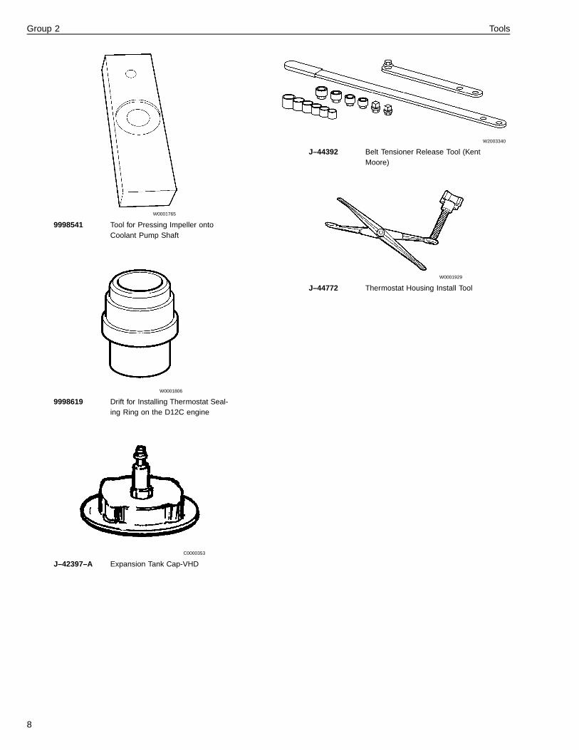
Group 2 Tools
W0001765
9998541 Tool for Pressing Impeller ontoCoolant Pump Shaft
W0001806
9998619 Drift for Installing Thermostat Seal-ing Ring on the D12C engine
C0000353
J–42397–A Expansion Tank Cap-VHD
W2003340
J–44392 Belt Tensioner Release Tool (KentMoore)
W0001929
J–44772 Thermostat Housing Install Tool
8
Group 2 Tools
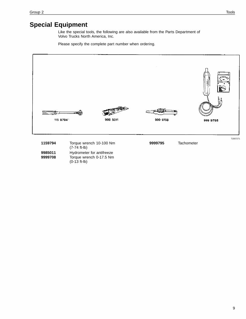
Special EquipmentLike the special tools, the following are also available from the Parts Department ofVolvo Trucks North America, Inc.
Please specify the complete part number when ordering.
T2007271
1159794 Torque wrench 10-100 Nm(7-74 ft-lb)
9985011 Hydrometer for antifreeze9999708 Torque wrench 0-17.5 Nm
(0-13 ft-lb)
9999795 Tachometer
9

10

Group 2 Design and Function
Design and Function
Cooling SystemCharge Air CoolerCharge Air Cooler Systems are essential today to meetemissions regulations. However, they also improvepower density, lower fuel consumption, and reduce ther-mal stresses on the engine by cooling the turbochargedair before it enters the engine. The turbocharged air isheated up to 200� C (400� F) or even higher as it entersthe charge cooler, and is cooled to around 40� C (100�
F) when it leaves for the engine.
Accumulation of bugs and dirt in the finned areas of aCharge Air Cooler are known problems. If there is abuild up of any debris like road film, bugs, etc. in just asection of a charge air cooler, that section overheats andtorsional (twisting) stresses develop in the charge aircooler core. The fin passage cleanliness may not be ascritical in an over-the-highway vehicle, but in construc-tion, logging and mining equipment, it can be.
Before performing the actual leak test, make sure thepressure regulator is functioning properly; see “CoolingSystem, Flow” page 12.
W2000730
Fig. 1: Charge air cooler
11

Group 2 Design and Function
Cooling System, Flow
W2003323
Fig. 2: Cooling system
1 Thermostat housing
2 Radiator
3 Expansion tank
4 Level sensor
5 Pressure cap
6 Coolant filter
7 Coolant pump
8 Heater return
9 Heater supply
10 Radiator drain valve
11 Shut-off valve—coolant pump
12

Group 2 Design and Function
Coolant Circulation in EngineThe coolant is forced through the system by a gear-driven pump. The coolant enters the cylinder blockthrough a pipe and first passes the area where the oilcooler is installed. The coolant is then distributedthrough galleries in the cylinder block and cylinder headto reach the cylinder liners and other parts of the enginebefore leaving the cylinder head through the thermostathousing. The illustration shows the engine during thewarm-up period. The thermostat is closed and thecoolant is flowing back to the coolant pump.
T2007265
Fig. 3: Coolant circulation
13

Group 2 Design and Function
ThermostatThe engine is equipped with a thermostat. The thermo-stat housing incorporates a sensor for coolanttemperature. During engine warm-up, the thermostat isclosed, (see Fig. 4: Thermostat closed , page 14) andcoolant flows from the cylinder head through the outersection of the thermostat back to the coolant pump.
W2003283
Fig. 4: Thermostat closed
When the engine has reached operating temperatureand the thermostat is open (see Fig. 5: Thermostat open,page 14) , the outlet to the coolant pump is graduallyclosed. The coolant now passes through the inner sec-tion of the thermostat housing and then to the radiator.
W2003284
Fig. 5: Thermostat open
14

Group 2 Design and Function
Thermostat Housing
D12CThe thermostat housing has been integrated into thecylinder head.
The thermostat (1) is located at the right front side of thecylinder head and its seal ring (2) is accessible once theconnection housing (3) and thermostat have been re-moved (see illustration, Fig. 6: Thermostat Housing,D12C, page 15).
T2012790
Fig. 6: Thermostat Housing, D12C
15
Group 2 Design and Function
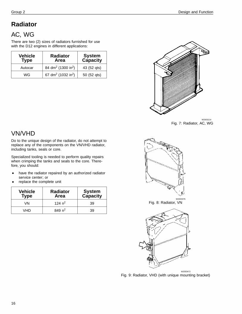
Radiator
AC, WGThere are two (2) sizes of radiators furnished for usewith the D12 engines in different applications:
VehicleType
RadiatorArea
SystemCapacity
Autocar 84 dm2 (1300 in2) 43 (52 qts)
WG 67 dm2 (1032 in2) 50 (52 qts)
W2003214
Fig. 7: Radiator, AC, WG
VN/VHDDo to the unique design of the radiator, do not attempt toreplace any of the components on the VN/VHD radiator,including tanks, seals or core.
Specialized tooling is needed to perform quality repairswhen crimping the tanks and seals to the core. There-fore, you should:
• have the radiator repaired by an authorized radiatorservice center; or
• replace the complete unit
VehicleType
RadiatorArea
SystemCapacity
VN 124 n2 39
VHD 849 n2 39
W2003376
Fig. 8: Radiator, VN
W2003472
Fig. 9: Radiator, VHD (with unique mounting bracket)
16

Group 2 Design and Function
Coolant MixtureAlways mix water and antifreeze to the correct concen-tration before filling the cooling system.
The recommended mixture is 50% antifreeze/coolant inthe water.
Note: Mixing concentrated coolants of a different typecan result in a loss of anti-corrosion properties with dam-age to the engine as a result.
At the factory, the cooling system is normally filled with amixture of tap water and concentrated coolant whichgives protection down to minimum -29� C (-20� F). If thevehicle is destined for climates colder than this, the anti-freeze level of the coolant should be adjusted; seeapproximate values in the following table.
CAUTION
60% antifreeze in the mixture gives optimum freezeprotection. Increasing the antifreeze content beyondthat will only decrease the freeze protection.
CAUTION
Never use a mixture weaker than 40% antifreeze to60% water. Ignoring this increases the risk of corro-sion in the cooling system and cylinder liner pittingleading to damage of the engine.
For more detailed information on Coolants, refer to:
TSI 184–001Coolant Requirements, Volvo Engines
IMPACT Function Group 184Information Type: Service and Mainte-nance”Coolant Requirements”
Freeze Protectiondown to: Amount
concentratedantifreeze,WG
Amountconcentratedantifreeze,WI and AC
Percent-age ofantifreezein mixture
-25�C(-13�F)
17 liters 20 liters 40%
-30�C(-22�F)
20 liters 23 liters 46%
-38�C(-36�F)
21 liters 25 liters 50%
-46�C(-51�F)
26 liters 30 liters 60%
17

Group 2 Design and Function
Flushing Cooling SystemThe cooling system should always be cleaned when thecoolant is replaced.
Coolant is toxic; risk of poisoning. Do not drinkcoolant. Use proper hand protection when handling.Keep coolant out of reach of children and animals.Failure to follow these precautions can cause seriousillness or death.
Note: Always dispose of coolant according to Federal orlocal regulations. Take all used coolant to a recycling orwaste collection center.
18
Group 2 Design and Function
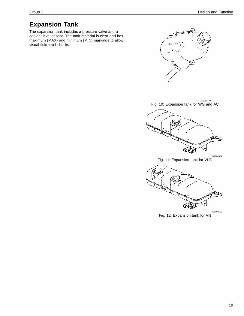
Expansion TankThe expansion tank includes a pressure valve and acoolant level sensor. The tank material is clear and hasmaximum (MAX) and minimum (MIN) markings to allowvisual fluid level checks.
W2000749
Fig. 10: Expansion tank for WG and AC
W2003514
Fig. 11: Expansion tank for VHD
W2003515
Fig. 12: Expansion tank for VN
19

Group 2 Design and Function
Draining PointsTo drain the cooling system, all drain points should beopened. In addition, the expansion tank cap should beremoved while the system is draining.
Draining points:
• Radiator• Cylinder block• Oil cooler, transmission (when installed)• Coolant pump
Note: In some locations the draining point consists of aquick-connect valve (1) covered with a rubber cap; seeFig. 13: Quick-connect drain valve in bottom of radiator,page 20. In this case use tool 9996049 for draining. Thisis a quick-connect hose needed for draining.
W2003367
Fig. 13: Quick-connect drain valve in bottom of radiator
Coolant PumpThe coolant pump is mounted to the timing gear plateand is driven by the timing gears. The coolant pump in-cludes a one-piece carbon/ceramic seal and a doubleball bearing for the pump shaft. The pump is equippedwith a shut-off valve (1) which prevents coolant fromdraining out when changing the coolant filter; see Fig.14: Coolant pump, page 20. To close the valve, the han-dle is turned to the horizontal position.
Note: The shut-off valve must always be in the open po-sition. That is, the handle should point vertically, exceptwhen replacing the lines.
W2003282
Fig. 14: Coolant pump
20

Group 2 Design and Function
Coolant FilterA coolant filter is mounted to the coolant pump. On D12engines and an adapter is mounted to the pump withlines to a remote-mounted coolant filter situated on theright side of the engine.
Coolant filters used with standard coolant include an anti-corrosive agent, SCA (Supplemental Coolant Additive),which is added to the standard coolant during filtration.
Coolant filters used with Extended Life Coolant, ELC,are “blanks” and do not contain any SCA.
Note: The valve must always be in the open position, i.e.the handle should point vertically, except when changingthe filter.
For more detailed information on coolants, refer to
TSI 184–001Coolant Requirements, Volvo Engines
IMPACT Function Group 184Information Type: Service and Mainte-nance”Coolant Requirements”
21

Group 2 Design and Function
WinterfrontVolvo Trucks North America, Inc. does not recommendthe use of winterfronts, shutters or any other shield infront of the grille or radiator package under normal cir-cumstances. These devices, if not used properly, cancause higher exhaust temperatures, power loss, exces-sive fan usage and a reduction in fuel economy.
Today’s electronically controlled engines are designed tooperate in temperatures without a winterfront. VolvoTrucks North America, Inc. does not recommend the useof a winterfront while the vehicle is being driven. If a win-terfront is used, it must conform to these specifications:
Note: Please see your local Volvo Truck Dealer for Volvorecommended winterfronts. If there is engine or relateddamage that can be followed back to an improperly usedwinterfront, the warranty is no longer valid for those parts.
VHD-Failure to remove the winterfront when tempera-tures go above 15� F (-25� C.) could cause severedamage to engine, charge-air-cooler and/or loss of fueleconomy. The grille cover should be able to let airflowthrough to the charge-air-cooler at a uniform rate overthe entire area. This means that a single, small openingin the winterfront is not acceptable. Air passage must bedistributed evenly across the grille and no more than85% can be covered.
VN-Winterfronts are properly used for overnight parkingin the winter or very cold temperatures (below-5� F[-20�
C]). In these cases, coolant and inlet manifold tempera-tures must be carefully monitored and controlled.
22

Group 2 Design and Function
Viscous FanThe Viscous fan consists of a fan section and a drivesection connected by a visco-static clutch. The clutchconsists of a drive plate (6) which is mounted in a hous-ing (7); see Fig. 17: Fan, cross-section, page 23.
On each side of the drive plate (6) is an air gap. Whenthe fan is engaged, these gaps are filled with fluid. Withthe fan in operation, the flow of fluid in the fan hub takesplace in two different ways. The temperature around thebimetallic plate (2) determines which path the fluid takesand thereby the degree to which the fan is engaged.
The control device regulates the amount of fluid reachingthe drive chamber to meet the cooling requirements. Themore fluid in the drive chamber, the less “slip,” thus re-sulting in higher fan speed. The fluid circulates betweenthe storage and drive chambers. When the engine andfan stop, the fluid runs out into the drive chamber, whichis why the fan is generally engaged during the first min-utes after starting the engine.
A. DisengagementThe valve (1) closes and fluid is pumped out into thestorage chamber (5).
B. EngagementThe valve (1) opens and fluid can enter the drive cham-ber (8).
T2006863
Fig. 15: Cooling fan
T2007216
Fig. 16: Sensor, bimetallic plate
T2007217
Fig. 17: Fan, cross-section
Fan, cross section shows valve disengaged (B)and engaged (A)1 Valve
2 Bimetallic plate
3 Control pin
4 Valve lever
5 Fluid storage chamber
6 Drive plate
7 Housing
8 Drive chamber
23

Group 2 Design and Function
Control DeviceThe fan rotates at reduced speed. The bimetallic plate(1) presses against the control pin (2) moving it towardsthe valve lever (3).
T2007218
Fig. 18: Control valve closed
1 Bimetallic plate
2 Control pin
3 Valve lever
The fan is fully engaged. The bimetallic plate flexes out-wards due to the temperature increase in the ambient air.
For function check, see “Viscous Fan, Checking” page68.
T2007219
Fig. 19: Control valve open
24

Group 2 Troubleshooting
TroubleshootingCooling System Troubleshooting
Coolant Temperature Too HighExcessively high coolant temperature can be due to:
• Blocked radiator (low airflow)
• Blocked cooling system
• Contaminated coolant
• Low coolant level
• Broken fan belt
• Faulty temperature gauge
• Poor grounding between engine and chassis
• Faulty thermostat
• Faulty temperature-controlled cooling fan
• Leaking cylinder head gasket, lower liner seals
• Leaking coolant hoses
Coolant Temperature Too Low• Faulty thermostat
• Faulty temperature gauge
Loss of Coolant
External Leaks• Leaks in hoses or connections
• Leaks in radiator and/or expansion tank
• Leaks in cab heater
• Leaks in coolant pump
• Cylinder head gasket leakage
Internal Leaks—Engine• Leak at injector copper sleeve
• Defective liner seals
• Liners pitted or cracked
• Cylinder head gasket leakage
• Crack(s) in cylinder head
• Crack(s) in cylinder block
25

Group 2 Troubleshooting
Coolant Leaks Through Overflow• Faulty pressure cap/relief valve
• Engine running too hot
• Expansion tank installed incorrectly
• Cylinder head gasket leakage
• Cylinder block cracked
• Liners pitted or cracked
• Coolant losses, warm engine switched off
Coolant losses after having switched off a warm engineare generally due to heavy load operation and subse-quent stopping without allowing the engine first to run atidling speed to cool down, or a faulty pressure cap valve.
Temperature Gauge, CheckingRemove the temperature sensor from the thermostathousing and reconnect the electric connector. Connect aground between the temperature sensor and the cylinderblock. Submerse the temperature sensor in heated water.Using a thermometer, read off the temperature. Comparethis reading with the reading of the temperature gauge.
Air Flow-through, CheckingShould higher than normal coolant temperatures be ob-served, the passage of air through the charge air cooler,A/C condenser and radiator must always be checked andcleaned if necessary. Any obstruction must be removed.
In cases of more serious blockage, the radiator/chargeair cooler and A/C condenser must be removed entirelyand thoroughly cleaned, especially if the pollutant is oilbased.
If the fins of the radiator have been bent by flying stonesetc., straighten them with a fin comb.
Check that the rubber seals between the fan shroud andthe radiator, and in some cases between the radiatorand the front shroud, have not loosened or for any otherreason are not providing a good seal.
Polluted CoolantIf the coolant is polluted it could mean that there is an in-ternal leak (oil) or that the cooling system is clogged(deposits). Check for leaks.
A clogged system is usually a result of not changing thecoolant according to the specific change intervals or us-ing the wrong mixture of coolant and water, or thatpolluted water has been used.
26

Group 2 Troubleshooting
Speed Check
Coolant is toxic; risk of poisoning. Do not drinkcoolant. Use proper hand protection when handling.Keep coolant out of reach of children and animals.Failure to follow these precautions can cause seriousillness or death.
Keep your hand, clothing, and the measuring instru-ment at a safe distance from the blades of the fanwhen checking RPM. Contact may cause personal in-jury or death.
WARNING
HOT ENGINE! Keep yourself and your test equipmentclear of all moving parts or hot engine parts and/orfluids. A hot engine and/or fluids can cause burns orcan permanently damage test equipment.
WARNING
Always wear appropriate eye protection to prevent therisk of eye injury due to contact with engine debris orfluids.
Fan Disengaged
W2003338
Fig. 20: Using hand-held tachometer
1Run the engine at idling speed for ap-proximately 5 minutes. Air temperaturein front of the fan must not exceed 30�
C (85� F). The silicone fluid, whichdrains into the drive chamber whenthe engine is switched off, is nowpumped back to the storage chamber.
1Increase engine speed to maximumRPM and measure fan speed with spe-cial tool 9999795. Fan speed shouldbe less than half engine speed whenthe fan is fully disengaged.
9999795
Fan EngagedAir temperature around the sensor should be approxi-mately 85� C (185� F) for the fan to be fully engaged.
W2003339
Fig. 21: Measuring fan speed
1Run the engine at maximum outputRPM and measure the fan speed andfan drive pulley speed using tool9999795. Fan speed must not be lessthan 90% of pulley speed when thefan is fully engaged.
9999795
27

28

Group 2 Service Procedures
Service Procedures2611-03-02-01Radiator, Replacement
Before working on a vehicle, set the parking brakes,place the transmission in neutral, and block thewheels. Failure to do so can result in unexpectedvehicle movement and can cause serious personal in-jury or death.
WARNING
HOT ENGINE! Keep yourself and your test equipmentclear of all moving parts or hot engine parts and/orfluids. A hot engine and/or fluids can cause burns orcan permanently damage test equipment.
WARNING
Never remove the cap on the expansion tank whilethe engine is still hot. Wait until the coolant tempera-ture is below 50� C (120� F). Scalding steam and fluidunder pressure may escape and cause serious per-sonal injuries.
WARNING
Do not work near the fan with the engine running. Theengine fan can engage at any time without warning.Anyone near the fan when it turns on could be seri-ously injured. Before turning on the ignition, be surethat no one is near the fan.
WARNING
Always wear appropriate eye protection to prevent therisk of eye injury due to contact with engine debris orfluids.
W2002101
Fig. 22: Lifting radiator and charge air cooler assembly
Note: WG, AC
The radiator and charge air cooler are removed andinstalled as an assembly. Use of a lifting strap during re-moval and installation will help to prevent damage to theradiator/charge air cooler assembly.
29

Group 2 Service Procedures
W2003376
Fig. 23: VN radiator
W2003472
Fig. 24: VHD radiator
Important: Do not attempt to replace any of the compo-nents on the VN/VHD radiator, including tanks, seals, orcore.
Specialized tooling is needed to perform quality repairswhen crimping the tanks and seals to the core. There-fore, you should:
• have the radiator repaired by an authorized radiatorservice center; or
• replace the complete unit.
Removal1• (VHD only) For removal of the
grille in a VHD model truck referto procedure:
TSI 820–500”Hood, VHD”
Impact Function Group82Information Type:RepairHood, VHD
•
W2002077
Fig. 25: VN model- screw fasteners
(VN only)
Remove the 14 Torx screws fas-tening the grille to the hood, andset the grille aside.
T25 Torx bit8 mm wrench
30
Group 2 Service Procedures
2
W2002059
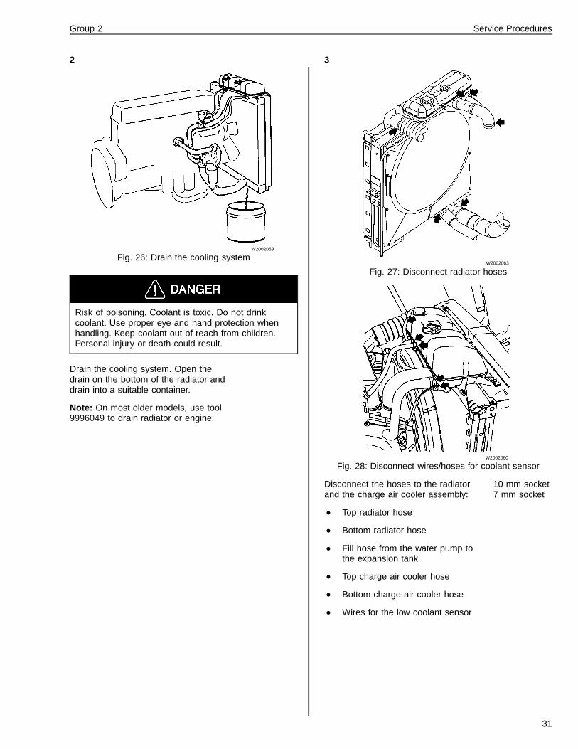
Fig. 26: Drain the cooling system
Risk of poisoning. Coolant is toxic. Do not drinkcoolant. Use proper eye and hand protection whenhandling. Keep coolant out of reach from children.Personal injury or death could result.
Drain the cooling system. Open thedrain on the bottom of the radiator anddrain into a suitable container.
Note: On most older models, use tool9996049 to drain radiator or engine.
9996049
3
W2002063
Fig. 27: Disconnect radiator hoses
W2002060
Fig. 28: Disconnect wires/hoses for coolant sensor
Disconnect the hoses to the radiatorand the charge air cooler assembly:
• Top radiator hose
• Bottom radiator hose
• Fill hose from the water pump tothe expansion tank
• Top charge air cooler hose
• Bottom charge air cooler hose
• Wires for the low coolant sensor
10 mm socket7 mm socket
31

Group 2 Service Procedures
4
W2002065
Fig. 29: Remove radiator mounts
Remove the four bolts fastening thelower radiator mounts.
13 mm socket
5
W2002078
Fig. 30: Remove bolts for support bracket
Remove the two upper bolts that fas-ten the air conditioning condenserupper support bracket to the chargeair cooler assembly.
Note: These bolts also mount the up-per CAC to the radiator.Remove the lower two bolts that fastenthe condenser itself to its lower sup-port brackets.
12 mm wrench12 mm socket13 mm wrench
6
W2002075
Fig. 31: Remove head screws
Remove the two torx head screws fas-tening the side shroud to the radiator.
T25 torx bit
7
W2002066
Fig. 32: Remove radiator fastener
Remove the one bolt that fastens theair conditioning lines to the radiator.
12 mm wrench
32

Group 2 Service Procedures
8
W2002071
Fig. 33: Lift out the condenser
Lift out the condenser, raise acrossthe top of the radiator and let rest ontop of the engine valve cover.
9
W2002072
Fig. 34: Plastic tie placement
Using plastic ties, tie the rubber part ofthe fan ring back away from the fanshroud.
10
W2002105
Fig. 35: Remove mounting bolts
Remove the four upper radiatormounting bolts.
15 mm deepsocket
33

Group 2 Service Procedures
11
W2002069
Fig. 36: Radiator removal
Fasten an acceptable lifting device tothe top of the radiator in the holes thatare provided. Lift out the radiator andthe charge air cooler assembly.
CAUTION
Be careful not to damage the radiator assembly whenremoving. Damage to the radiator and/or engine couldresult in severe damage to the engine.
OEM 4129
Installation1
W2002069
Fig. 37: Lowering radiator
Position the radiator into the truck.
Note: Be very careful when loweringthe radiator into the truck. Watch forany hoses or wires that might interfereor be damaged. Make sure the fandoes not damage the radiator core as-sembly.
2Remove the lifting device from the ra-diator.
34
Group 2 Service Procedures
3
W2002105
Fig. 38: Install the radiator mounts
Install the upper radiator mounts andnuts. Torque to 48 ± 8 Nm (36 ± 6 ft-lb).
15 mm socket48 ± 8 Nm(18 ± 3 ft-lb)
4
W2002065
Fig. 39: Install the supports and ties
Install the lower radiator supports andnuts. Torque to 24 ± 4 Nm (18 ± 3 ft-lb).
13 mm socket24 ± 4 Nm(18 ± 3 ft-lb)
5
W2002060
Fig. 40: Install expansion tank hoses
W2002063
Fig. 41: Connect top hose clamps
Install all coolant hoses on the top sideof the radiator. Connect the following:
• charge air cooler hose• low coolant sensor harnessTorque the hose clamps as follows:
• top radiator hose 5.5 ± 0.8 Nm(50 ± 8 in-lb).
• fill hose clamp 4 ± 0.6 Nm (35 ± 5in-lb).
• small bleed hose clamp 2.3 ± 0.3Nm (20 ± 3 nibble)
• charge air cooler hose clamp to10 ± 1.5 Nm (90 ± 3 in-lb).
7 mm socket10mm socketscrewdriver5.5 ± 0.8 Nm(50 ± 8 in-lb)4 ± 0.6 Nm(35 ± 5 in-lb)2.3 ± 0.3 Nm(20 ± 3 in-lb)10 ± 1.5 Nm(90 ± 3 in-lb)
35

Group 2 Service Procedures
6
W2002063
Fig. 42: Connect bottom hose clamps
Install the bottom radiator hose andthe lower charge air cooler hose.Torque the hose clamps as follows:
• bottom radiator hose clamp 5.5 ±0.8 Nm (50 ± 8 in-lb).
• lower charge air cooler hoseclamp 10 ± 1.5 Nm (90 ± 13 in-lb).
7 mm socket10 mm sockettorque wrench5.5 ± 0.8 Nm(50 ± 8 in-lb)10 ± 1.5 Nm(90 ± 13 in-lb)
7
W2002072
Fig. 43: Tie removal
Cut the four ties holding the rubbershrouding away from the radiator.
8
W2002078
Fig. 44: Install mounting brackets
Position the condenser onto the lowermounting brackets. Install the con-denser mounting bolts and torque to24 ± 4 Nm (18 ± 3 ft-lb).Torque the lower condenser mountingbracket bolts (previously hand tight) to24 ± 4 Nm (18 ± 3 ft-lb).
12 mm socket24 ± 4 Nm(18 ± 3 ft-lb)24 ± 4 Nm(18 ± 3 ft-lb)
9
W2002066
Fig. 45: Install air conditioner line clamp
Install the bolt supporting the air con-ditioner line clamp. Torque the lineclamp bolt to 24 ± 4 Nm (18 ± 3 ft-lb).
12mm wrench24 ± 4 Nm(18 ± 3 ft-lb)
36

Group 2 Service Procedures
10
W2002075
Fig. 46: Install head screws
Position the side shroud into place, in-stall two torx head screws and handtighten.
T25 torx bit
11
W2002058
Fig. 47: Add coolant
Add the drained coolant. Maximum fillrate of 9.5 liter per minute (2.5 gallonsper minute). For more detailed infor-mation on Coolants, refer to;
TSI 184–001Coolant Require-ments, Volvo Engines
IMPACT Function Group 184Information Type: Ser-vice and Maintenance”Coolant Require-ments”
12
W2002077
Fig. 48: Install grille
Install grille and torque the 14 Torxhead screws to 5 Nm (44 in-lb).
T25 Torx bit8mm wrench5 Nm(44 in-lb)
13
W2002104
Fig. 49: Cap replacement
1 Fill cap2 Pressure cap (do not remove)
Start engine and check for leaks. Runthe engine to operating temperature.After the engine has reached operat-ing temperature, move the heatercontrols to warm and run the enginean additional 10 minutes.
14Shut off engine and re-check coolantlevel.
Note: To pressure test the system,see “Cooling System Leak Test,Checking” page 41.
37

Group 2 Service Procedures
2611-06-02-01Radiator, Checking
Before working on a vehicle, set the parking brakes,place the transmission in neutral, and block thewheels. Failure to do so can result in unexpectedvehicle movement and can cause serious personal in-jury or death.
WARNING
HOT ENGINE! Keep yourself and your test equipmentclear of all moving parts or hot engine parts and/orfluids. A hot engine and/or fluids can cause burns orcan permanently damage test equipment.
WARNING
Never remove the cap on the expansion tank whilethe engine is still hot. Wait until the coolant tempera-ture is below 50� C (120� F). Scalding steam and fluidunder pressure may escape and cause serious per-sonal injuries.
WARNING
Do not work near the fan with the engine running. Theengine fan can engage at any time without warning.Anyone near the fan when it turns on could be seri-ously injured. Before turning on the ignition, be surethat no one is near the fan.
WARNING
Always wear eye protection when working around bat-teries to prevent the risk of injury due to contact withsulfuric acid or an explosion.
(Checking CAC and Radiator Air Flow-Through)
1If coolant temperatures are higherthan normal, check the passage of airthrough the charge air cooler, A/Ccondenser and radiator. Clean if nec-essary.
2Check the radiator to make sure thatits external sections are not blocked byinsects or other foreign objects whichcan obstruct airflow. If obstructions arefound, use a mild detergent and waterto clean them off. If the fins of the pipesystem have been bent (by flyingstones, etc.), straighten them out.
3Make sure that the sealing moldingsbetween the fan shroud and the radia-tor are not loose or for any reason arenot providing a good seal. Check thecondition of the recirculation shield.Also make sure it is properly installed.
2612-03-02-01Radiator Surge Tank, Replace-ment
Before working on a vehicle, set the parking brakes,place the transmission in neutral, and block thewheels. Failure to do so can result in unexpectedvehicle movement and can cause serious personal in-jury or death.
WARNING
HOT ENGINE! Keep yourself and your test equipmentclear of all moving parts or hot engine parts and/orfluids. A hot engine and/or fluids can cause burns orcan permanently damage test equipment.
WARNING
Never remove the cap on the expansion tank whilethe engine is still hot. Wait until the coolant tempera-ture is below 50� C (120� F). Scalding steam and fluidunder pressure may escape and cause serious per-sonal injuries.
WARNING
Do not work near the fan with the engine running. Theengine fan can engage at any time without warning.Anyone near the fan when it turns on could be seri-ously injured. Before turning on the ignition, be surethat no one is near the fan.
38

Group 2 Service Procedures
WARNING
Always wear appropriate eye protection to prevent therisk of eye injury due to contact with engine debris orfluids.
Removal
1
W2002059
Fig. 50: Draining the coolant system
Open the drain on the bottom of theradiator and drain into a suitablecontainer. Drain coolant below the ex-pansion tank level.
Risk of poisoning. Coolant is toxic. Do not drinkcoolant. Use proper eye and hand protection whenhandling. Keep coolant out of reach of children. Per-sonal injury or death could result.
2
W2002060
Fig. 51: Remove expansion tank hoses
Remove the four expansion tankhoses:
• overfill tube• fill line• air bleed hose (to thermostat
housing)• hose from expansion tank to radi-
ator top tankUnplug the wire harness to the lowcoolant sensor.
12 mm socket6 in. extension
39

Group 2 Service Procedures
3
W2002062
Fig. 52: Remove mounting bolts
W2002061
Fig. 53: Lift the expansion tank
Remove the expansion tank mountingbolts (two in the front, three in therear). Lift away the expansion tank.
12 mm socket
Installation
4
W2002062
Fig. 54: Install mounting bolts
Position the expansion tank into placeand install the five mounting bolts.Torque to 24 ± 4 Nm (18 ± 3 ft-lb).
12 mm socket24 ± 4 Nm(18 ± 3 ft-lb)
5
W2002060
Fig. 55: Connect expansion tank hoses
Connect the four expansion tankhoses:
• overfill tube• fill line• air bleed hose (to thermostat
housing)• hose from expansion tank to radi-
ator top tankConnect the wire harness to the lowcoolant sensor.
7 mm socketscrewdriver
40

Group 2 Service Procedures
6
W2002058
Fig. 56: Add coolant
Install the drained coolant. Maximumfill rate of 9.5 l/min (2.5 gpm).
Note: For current coolant require-ments;
ServiceBulletin
184–001Coolant Require-ments, Volvo Engines
IMPACT Function group 184Information type:Maintenance”Coolant Require-ments”
7Start engine and check for leaks. Runthe engine to operating temperature.After the engine has reached operat-ing temperature, move the heatercontrols to warm and run the enginean additional 10 minutes.
8Shut off engine and recheck coolantlevel.
Note: To pressure test the system,see “Cooling System Leak Test,Checking” page 41.
2619-06-02-01Cooling System Leak Test,Checking
Before working on a vehicle, set the parking brakes,place the transmission in neutral, and block thewheels. Failure to do so can result in unexpectedvehicle movement and can cause serious personal in-jury or death.
WARNING
HOT ENGINE! Keep yourself and your test equipmentclear of all moving parts or hot engine parts and/orfluids. A hot engine and/or fluids can cause burns orcan permanently damage test equipment.
WARNING
Never remove the cap on the expansion tank whilethe engine is still hot. Wait until the coolant tempera-ture is below 50� C (120� F). Scalding steam and fluidunder pressure may escape and cause serious per-sonal injuries.
WARNING
Do not work near the fan with the engine running. Theengine fan can engage at any time without warning.Anyone near the fan when it turns on could be seri-ously injured. Before turning on the ignition, be surethat no one is near the fan.
WARNING
Always wear appropriate eye protection to prevent therisk of eye injury due to contact with engine debris orfluids.
41

Group 2 Service Procedures
To be carried out in the vehicle
Note: Before using pressure gauge 9996662, check itsoperation. Do this by attaching it to an air supply andsetting the pressure to 100 kPa (14 psi) with the regula-tor valve.
Check that the pressure on the gauge never exceeds100 kPa (14 psi). Excessive pressure may cause airsupply to burst which can cause personal injury ordeath.
ProcedureSpecial tools: 9996049, 9996662
1Check the hoses and connections ofthe cooling system for leaks and tomake sure they are in good workingcondition.
2
W2001430
Fig. 57: Remove fill cap –VN Model
W2003473
Fig. 58: Remove fill cap –VHD Model
Remove the fill cap and installpressure regulator, gauge and cap as-sembly.
Note: Make sure the cooling systemis full of coolant before performing thistest.
9996662J–42397
42

Group 2 Service Procedures
3
T2007258
Fig. 59: Increase pressure to 40 kPa (6 psi)
Using the knob of the reduction valve,slowly increase pressure to 40 kPa (6psi). Maintain this pressure for approx-imately 5 minutes. Look over the entireengine, radiator, and coolant hoses forany leaks.and then perform a leakagecheck on the radiator, hoses, connec-tions, and the coolant pump.
4
T2007257
Fig. 60: Increase pressure to 100 kPa (14 psi)
Slowly increase the pressure to 100kPa (14 psi) and check that the valveopens. At this pressure, the air flowshould be continuous. End this test af-ter approximately 10 seconds.
5Slowly release the pressure from thecooling system. Remove the cap as-sembly and replace the fill cap.
2621-03-02-01Coolant Pump, Replacement
Before working on a vehicle, set the parking brakes,place the transmission in neutral, and block thewheels. Failure to do so can result in unexpectedvehicle movement and can cause serious personal in-jury or death.
WARNING
HOT ENGINE! Keep yourself and your test equipmentclear of all moving parts or hot engine parts and/orfluids. A hot engine and/or fluids can cause burns orcan permanently damage test equipment.
WARNING
Never remove the cap on the expansion tank whilethe engine is still hot. Wait until the coolant tempera-ture is below 50� C (120� F). Scalding steam and fluidunder pressure may escape and cause serious per-sonal injuries.
WARNING
Always wear appropriate eye protection to prevent therisk of eye injury due to contact with engine debris orfluids.
Special tools: 9996049
43

Group 2 Service Procedures
Removal1
W2003324
Fig. 61: Draining the coolant
Attach hose 9996049 to lower coolantpipe and drain the coolant into a suit-able container.
Note: If the coolant is not reusable,dispose of used coolant in a properand responsible manner according toEPA and local environmental regula-tions
9996049
2
W2003334
Fig. 62: Charge air cooler piping
Remove charge air cooler pipe andmounting brackets.
3Remove the elbow outlet from the tur-bocharger.
4
W2003328
Fig. 63: Removing coolant pipes
Remove the pipe between the coolantpump and the cover over the oil cooler.
5Remove the pipe between the pumpand the thermostat housing.
44

Group 2 Service Procedures
6
W2003329
Fig. 64: Bolt location
Remove the bolt beside the thermostathousing holding the pipe betweencoolant pump and the expansion tank.
7Remove the bolt from the coolantpump and pull the pipe out of thepump.
Note: The bolt beside the thermostathousing runs through a bracket on thepipe. With the air compressor in posi-tion, the pipe cannot be removed.
8
T2007246
Fig. 65: Heater hose location
Remove the heater hose from thecoolant pump.
9Remove the drain hose from the lowercoolant pipe.
10
W2003330
Fig. 66: Lower radiator pipe location
Remove the bolts holding the lowercoolant pipe to the pump.
Note: Leave the pipe attached to thelower radiator hose.
45

Group 2 Service Procedures
11Remove the coolant filter hoses.
12
W2003332
Fig. 67: Removing coolant pump
Remove the bolts and lift off thecoolant pump.
13Remove the adapter for the remotecoolant filter from the bottom of thecoolant pump.
Installation1Clean all sealing surfaces.
2
W2003331
Fig. 68: Installing coolant pump
Install the new coolant pump usingnew seals. Tighten the bolts to 48 ± 8Nm (35 ± 6 ft-lb).
48 ± 8 Nm(35 ± 6 ft-lb)
3
W2003330
Fig. 69: Pipe from radiator to coolant pump
Install the pipe from the radiator to thecoolant pump using a new sealing ring.
46
Group 2 Service Procedures
4
T2007246
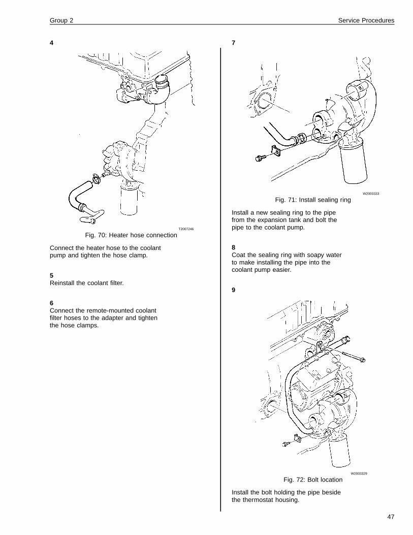
Fig. 70: Heater hose connection
Connect the heater hose to the coolantpump and tighten the hose clamp.
5Reinstall the coolant filter.
6Connect the remote-mounted coolantfilter hoses to the adapter and tightenthe hose clamps.
7
W2003333
Fig. 71: Install sealing ring
Install a new sealing ring to the pipefrom the expansion tank and bolt thepipe to the coolant pump.
8Coat the sealing ring with soapy waterto make installing the pipe into thecoolant pump easier.
9
W2003329
Fig. 72: Bolt location
Install the bolt holding the pipe besidethe thermostat housing.
47

Group 2 Service Procedures
10
W2003328
Fig. 73: Installing coolant pipe
Using new sealing rings, install thepipe between the coolant pump andthe thermostat housing and the pipebetween the coolant pump and the oilcooler cover.
11Coat the sealing rings with soapy wa-ter.
12
W2003334
Fig. 74: Charge air cooler piping
Reinstall the charge air cooler pipeand mounting brackets.
13Reinstall the elbow outlet on the tur-bocharger.
14
W2003335
Fig. 75: Coolant filter
Install a new coolant filter on thecoolant pump.
15Fill the system with coolant.
16Start the engine and check the coolingsystem for leaks.
2621-04-04-01Coolant Pump, Overhaul
(Unit Removed)
Before working on a vehicle, set the parking brakes,place the transmission in neutral, and block thewheels. Failure to do so can result in unexpectedvehicle movement and can cause serious personal in-jury or death.
WARNING
HOT ENGINE! Keep yourself and your test equipmentclear of all moving parts or hot engine parts and/orfluids. A hot engine and/or fluids can cause burns orcan permanently damage test equipment.
WARNING
Never remove the cap on the expansion tank whilethe engine is still hot. Wait until the coolant tempera-ture is below 50� C (120� F). Scalding steam and fluidunder pressure may escape and cause serious per-sonal injuries.
48

Group 2 Service Procedures
WARNING
Do not work near the fan with the engine running. Theengine fan can engage at any time without warning.Anyone near the fan when it turns on could be seri-ously injured. Before turning on the ignition, be surethat no one is near the fan.
WARNING
Always wear appropriate eye protection to prevent therisk of eye injury due to contact with engine debris orfluids.
T2007117
Fig. 76: Exploded view of coolant pump
Note: Reference is made in the text to component posi-tions as shown in picture.
1 Shaft
2 Shaft sleeve
3 Ball Bearing
4 Gear
5 Pump Housing
6 Oil Sealing Ring
7 Coolant Sealing Ring
8 Impeller
9 O-ring
10 Rear Cover
11 Coolant Filter
Special tools: 9992071, 9992671, 9994034,9994090, 9996222, 9996315, 9996383,
9996626, 9996883, 9996884, 9998012,9998039, 9998113, 9996671
Disassembly1Remove the coolant filter (11), usingfilter wrench 9996671. Remove therear cover (10); see Fig. 76: Explodedview of coolant pump, page 49.
9996671
2
T2007116
Fig. 77: Attaching tools to coolant pump
Screw adapter 9996883 into the shaftsleeve (2) of the coolant pump andthread drift 9996884 onto hydrauliccylinder 9992671; see Fig. 76: Ex-ploded view of coolant pump, page 49.
999688399968849992671
3
T2007118
Fig. 78: Removing the shaft
Assemble the hydraulic cylinder andthe adapter. Using hydraulic pump9996222, press out the shaft (1) theimpeller (8) and the seal (7); see Fig.76: Exploded view of coolant pump,page 49.
999688399962229992671
49

Group 2 Service Procedures
4
W2003285
Fig. 79: Coolant seal, removal
If parts of the coolant seal do notcome out with the shaft when pressingthis out, use puller 9994090 to removethe rest of the sealing ring.
9994090
5
T2007108
Fig. 80: Removing the oil sealing ring
Remove the seal (6) using tool9994090; see Fig. 76: Exploded viewof coolant pump, page 49.
9994090
6
T2007109
Fig. 81: Removing shaft sleeve, drive gear and bearing
Place the pump housing in a press.Using 9994034, carefully press out theshaft sleeve (2) together with the drivegear (4) and bearing (3); see Fig. 76:Exploded view of coolant pump, page49.
9994034
50

Group 2 Service Procedures
7
T2007248
Fig. 82: Removing the shaft sleeve from drive gear
Using 9992071 and 9996383, pressthe shaft sleeve (2) out of the drivegear (4); see Fig. 76: Exploded view ofcoolant pump, page 49.
99920719996383
Cleaning and Inspection
T2007117
Fig. 83: Exploded view of coolant pump
1Clean all parts which are to be reused.
2The seals and bearing must always bechanged. Check the fit of the bearingraces to the pump housing and shaftsleeve.
Note: If the impeller is damaged, itmust be replaced.
Note: If the pump housing or rearcover is to be replaced, transfer pipefittings to the replacement unit, etc.
51

Group 2 Service Procedures
Assembly1
T2007111
Fig. 84: Installing bearing to shaft sleeve
Install the new bearing (3) to the shaftsleeve (2) and, using hollow drift9998012, carefully press down on theinner race of the bearing until it lies upagainst the flange of the shaft sleeve;see Fig. 83: Exploded view of coolantpump, page 51.
Note: Install the bearing with the sideat which the outer and inner races arelevel facing the flange of the shaftsleeve. The shaft (1) and the shaftsleeve (2) are supplied as a singlespare part unit; see Fig. 83: Explodedview of coolant pump, page 51.
9998012
2
T2007112
Fig. 85: Installing bearing and shaft into pump
Place the pump housing (5) in a press.Using hollow drift 9996383, carefullypress in the bearing and shaft until thebearing bottoms out in the pump hous-ing; see Fig. 83: Exploded view ofcoolant pump, page 51.
Note: Press on the outer race of thebearing and check to make sure thatthe shaft does not hit the press table.
9996383
3
T2007119
Fig. 86: Press drive gear onto shaft
Screw the shorter threaded section ofspindle 9996315 into the shaft sleeve(2); see Fig. 83: Exploded view ofcoolant pump, page 51.
9996315
52

Group 2 Service Procedures
4Place the drive gear (4), hollow drift9996626 and hydraulic cylinder9992671 on the spindle and install thenut; see Fig. 83: Exploded view ofcoolant pump, page 51.
99962669992671
5Using hydraulic pump 9996222, care-fully press the drive gear down until itbottoms out against the bearing.
9996222
6Remove the tools
7
T2012619
Fig. 87: Using tool 9996315
Insert the spindle 9996315 through thehole of sleeve 9998244 and screw thelong threaded end of the spindle intothe shaft until it bottoms out againstthe shaft. Tighten the nut by hand.
Note: Make sure that the spindle9996315 is threaded in until it bottomsout against the shaft before tighteningthe nut.
99963159998244
8Install the pump in a press so that thespindle’s nut rests flat against the sur-face of the press.
9
T2012620
Fig. 88: Installing the oil seal
Install the oil seal (6) with the sealinglip against the drive gear; see Fig. 83:Exploded view of coolant pump, page51.
10Using drift 9998113, carefully pressthe seal into position until it is levelwith the edge of the pump housing.
Note: Do not press in the drift until ithits the pump housing.
9998113
11
T2012621
Fig. 89: Coolant seal, applying Loc-TiteTM
.
Apply Loc-TiteTM
locking fluid to thecoolant seal’s contact surface (A)against the housing.
53

Group 2 Service Procedures
12
T2007262
Fig. 90: Installing the coolant seal
Carefully press in the coolant seal us-ing the drift 9998039.
Note: To prevent damage due to ex-cessive pressing force, pressureshould be removed when the sealflanges out against the housing.
9998039
13
T2007115
Fig. 91: Installing new impeller
Place the pump with the spindle nutresting on a flat surface.
14Press the impeller approximately 10mm (1/2 in.) on to the shaft.
15
W2003286
Fig. 92: Pressing on the impeller
Install the tool 9998541 on the impellerand carefully press it down until thetool rests against the pump housing.
9998541
16Remove the spindle 9996315 from theshaft sleeve.
9996315
17Install the rear cover using a new O-ring in the pump housing.
Note: Turn the drive gear and checkthat it rotates easily. Bearing noise oraxial play is not permitted.
18Install a new coolant filter. Coat the fil-ter gasket with a light film of greaseand hand tighten only.
54
Group 2 Service Procedures
2627-03-02-01Thermostat, ReplacementD12, D12A, D12B
Before working on a vehicle, set the parking brakes,place the transmission in neutral, and block thewheels. Failure to do so can result in unexpectedvehicle movement and can cause serious personal in-jury or death.
WARNING
HOT ENGINE! Keep yourself and your test equipmentclear of all moving parts or hot engine parts and/orfluids. A hot engine and/or fluids can cause burns orcan permanently damage test equipment.
WARNING
Never remove the cap on the expansion tank whilethe engine is still hot. Wait until the coolant tempera-ture is below 50� C (120� F). Scalding steam and fluidunder pressure may escape and cause serious per-sonal injuries.
WARNING
Do not work near the fan with the engine running. Theengine fan can engage at any time without warning.Anyone near the fan when it turns on could be seri-ously injured. Before turning on the ignition, be surethat no one is near the fan.
WARNING
Always wear appropriate eye protection to prevent therisk of eye injury due to contact with engine debris orfluids.
Special tools: 9996049 , 99982911Using drain hose 9996049, drain thecoolant into suitable container.
2Remove the pipe between the aircleaner housing and the turbo-compressor.
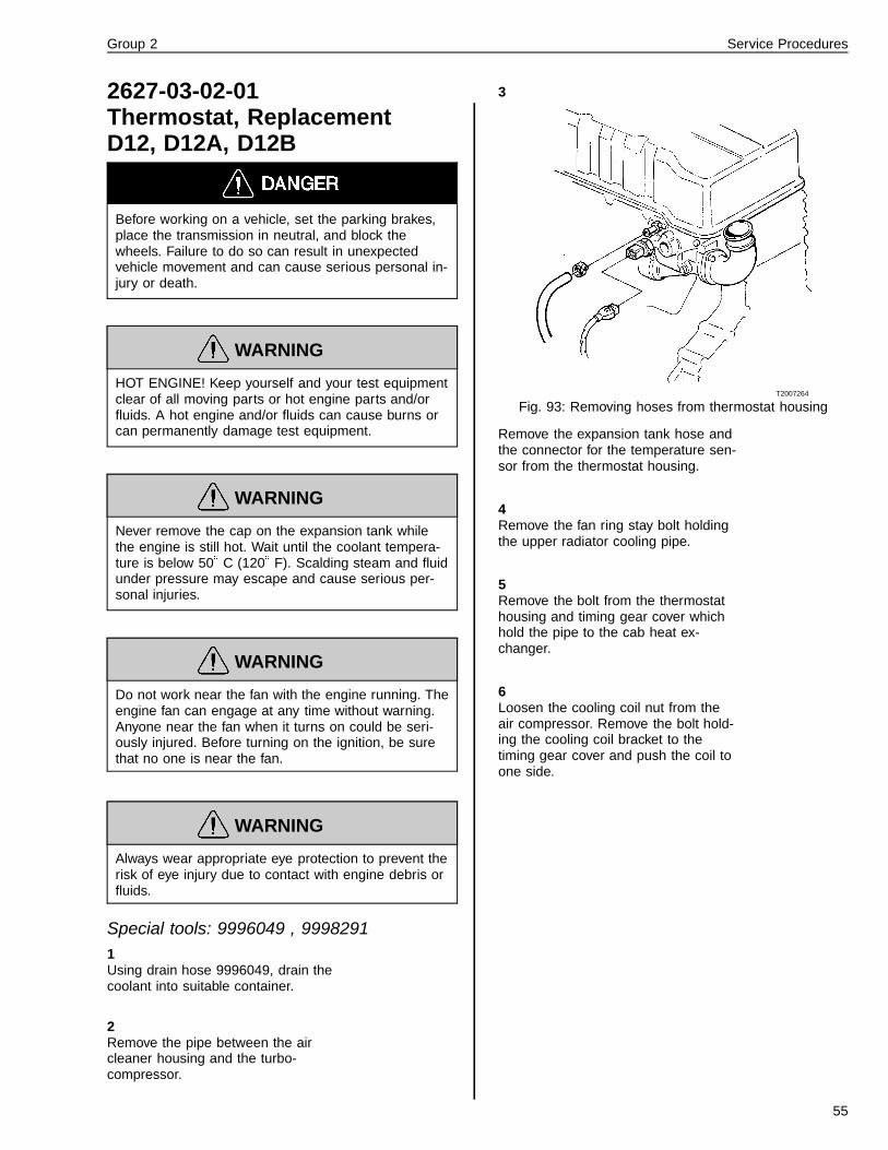
3
T2007264
Fig. 93: Removing hoses from thermostat housing
Remove the expansion tank hose andthe connector for the temperature sen-sor from the thermostat housing.
4Remove the fan ring stay bolt holdingthe upper radiator cooling pipe.
5Remove the bolt from the thermostathousing and timing gear cover whichhold the pipe to the cab heat ex-changer.
6Loosen the cooling coil nut from theair compressor. Remove the bolt hold-ing the cooling coil bracket to thetiming gear cover and push the coil toone side.
55
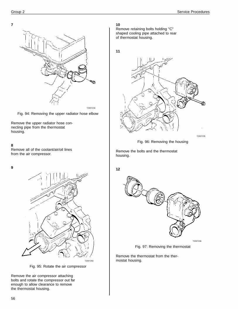
Group 2 Service Procedures
7
T2007234
Fig. 94: Removing the upper radiator hose elbow
Remove the upper radiator hose con-necting pipe from the thermostathousing.
8Remove all of the coolant/air/oil linesfrom the air compressor.
9
T2007250
Fig. 95: Rotate the air compressor
Remove the air compressor attachingbolts and rotate the compressor out farenough to allow clearance to removethe thermostat housing.
10Remove retaining bolts holding "C"shaped cooling pipe attached to rearof thermostat housing.
11
T2007235
Fig. 96: Removing the housing
Remove the bolts and the thermostathousing.
12
T2007236
Fig. 97: Removing the thermostat
Remove the thermostat from the ther-mostat housing.
56

Group 2 Service Procedures
13
T2007238
Fig. 98: Removing the sealing ring
Remove the sealing ring from the ther-mostat housing by tapping with a driftuntil it tips over and can be removed.
14Clean the sealing surfaces of the ther-mostat housing and the sealingsurfaces of the cylinder head and pipeconnections.
15
T2007243
Fig. 99: Installing a new sealing ring
Install a new sealing ring to drift9998291.
Note: The sealing ring must be in-stalled with the broad metal platefacing the ledge on the drift.
9998291
16
T2007242
Fig. 100: Installing a new sealing ring
Using drift 9998291, carefully tap thesealing ring in until it bottoms out inthe housing.
9998291
17
T2007237
Fig. 101: New thermostat and seal
Install a new thermostat and a newseal into the housing.
18Remove the bolts holding the spacerbetween the coolant pump and thethermostat housing. Install a new seal-ing ring to the spacer and coat it withgrease.
57

Group 2 Service Procedures
19
T2007235
Fig. 102: Reattaching the thermostat housing
Install and attach the thermostat hous-ing to the cylinder head.
20Push the pipe from the coolant pumpinto the thermostat housing entry andinstall the bolts holding the pipe.
21
T2007240
Fig. 103: New air compressor seal
Install a new seal between the aircompressor and the timing gear plate.Attach the air compressor.
22Reinstall all of the coolant/air/oil linesto the air compressor.
23Install the pipe between the radiatorand the thermostat housing. Use anew sealing ring.
24Attach the cab heater pipe to the ther-mostat housing. Install a new sealingring.
25Attach the fan ring stay.
26
T2007264
Fig. 104: Reattaching the hoses to thermostat housing
Plug in the temperature sensor con-nector and attach the expansion tankhose.
27Fill with coolant and carry out a leak-age check.
58

Group 2 Service Procedures
2627-03-02-01Thermostat, Replacement
D12C
Before working on a vehicle, set the parking brakes,place the transmission in neutral, and block thewheels. Failure to do so can result in unexpectedvehicle movement and can cause serious personal in-jury or death.
WARNING
HOT ENGINE! Keep yourself and your test equipmentclear of all moving parts or hot engine parts and/orfluids. A hot engine and/or fluids can cause burns orcan permanently damage test equipment.
WARNING
Never remove the cap on the expansion tank whilethe engine is still hot. Wait until the coolant tempera-ture is below 50� C (120� F). Scalding steam and fluidunder pressure may escape and cause serious per-sonal injuries.
WARNING
Do not work near the fan with the engine running. Theengine fan can engage at any time without warning.Anyone near the fan when it turns on could be seri-ously injured. Before turning on the ignition, be surethat no one is near the fan.
WARNING
Always wear appropriate eye protection to prevent therisk of eye injury due to contact with engine debris orfluids.
Special tools: 9996049, 9998619, 9998511Other special equipment: 945408, 946173,949873, 955894
1Drain off the coolant with drain hose9996049.
9996049
2Remove the two bolts for the exhaustcollector pipe located next to the ther-mostat housing.
3Remove the thermostat housing fromthe engine.
4Remove piston thermostat from thecylinder head.
5
W2003428
Fig. 105: Remove the sealing ring
Remove the sealing ring from thecylinder head, tapping the sealing ringwith a drift so that it is lifted up andcan be removed.
6Clean all the sealing surfaces and pipeconnections.
59

Group 2 Service Procedures
7
W2003427
Fig. 106: Checking that the sealing ring is correctly posi-tioned
Place a new sealing ring on drift9998619.
Note: The ring should be turned withthe wide plate edge facing the shoul-der of the drift.
9998619
8Install the thermostat housing andtighten the bolts by hand.
9
W2003482
Fig. 107: Thermostat housing remove tool
Press drift J–44472 into the cylinderhead until the drift reaches the bottomof the cylinder head.
J-44772
10Install the new piston thermostat.Lubricate the seal on the piston ther-mostat with soapy water.
11Install the thermostat housing andtighten the bolts by hand.
Note: Make sure that the gasket to thecylinder head is correctly positioned.Use a new gasket.
12
W2003539
Fig. 108: Tighten the thermostat housing bolts in the se-quence shown
Tighten the thermostat housing’s boltsin the sequence shown in the illustra-tion (1–2–3). Tighten to a torque asper the specifications for standardbolts.
Note: Remember to remove the ten-sioning bolt (M8x20).
13Install the bolts between the exhaustmanifold and the thermostat housinguntil they push against the seal.Tighten to the specified torque.
14Connect the remaining coolant line.
15Fill with approved coolant.
16Start the engine.
Run the engine until it is at operatingtemperature. Then run at 1800 rpmand check for leaks.
60

Group 2 Service Procedures
2627-06-05-01Thermostat, Checking
WARNING
Always wear appropriate eye protection to prevent therisk of eye injury due to contact with engine debris orfluids.
A function check must be carried out before in-stalling a new thermostat.
Note: Check to be sure that the thermostat closes fully.This can be done by holding it up to the light to checkthat there is no visible gap at the opening point. If thethermostat does not close properly, replace it.
1
T2007256
Fig. 109: Checking the thermostat
Warm up water in a receptacle to 75�C (167� F) and immerse the thermo-stat in the water as illustrated.
Use a piece of wire attached to thethermostat.
2After at least 30 seconds, check thatthe thermostat is still closed.
3
T2007255
Fig. 110: Checking the thermostat
Now warm the water to 100� C (212�
F). After at least 30 seconds at boilingpoint, check that the thermostat hasopened at least 7 mm (9/32 in). If thethermostat has not opened, it must bereplaced. A good thermostat starts toclose at 95� C (203� F) and is fullyclosed at approximately 85� C (185�
F).
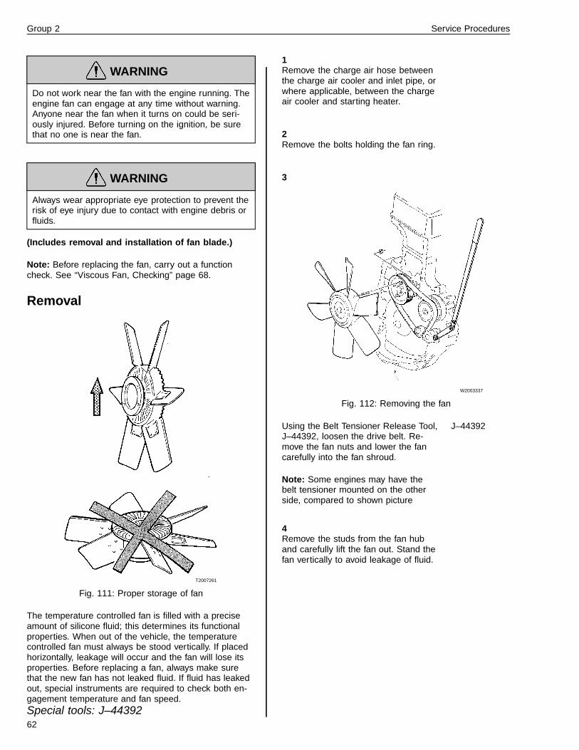
2631-03-02-01Viscous Fan, Replacement
Before working on a vehicle, set the parking brakes,place the transmission in neutral, and block thewheels. Failure to do so can result in unexpectedvehicle movement and can cause serious personal in-jury or death.
WARNING
HOT ENGINE! Keep yourself and your test equipmentclear of all moving parts or hot engine parts and/orfluids. A hot engine and/or fluids can cause burns orcan permanently damage test equipment.
WARNING
Never remove the cap on the expansion tank whilethe engine is still hot. Wait until the coolant tempera-ture is below 50� C (120� F). Scalding steam and fluidunder pressure may escape and cause serious per-sonal injuries.
61
Group 2 Service Procedures
WARNING
Do not work near the fan with the engine running. Theengine fan can engage at any time without warning.Anyone near the fan when it turns on could be seri-ously injured. Before turning on the ignition, be surethat no one is near the fan.
WARNING
Always wear appropriate eye protection to prevent therisk of eye injury due to contact with engine debris orfluids.
(Includes removal and installation of fan blade.)
Note: Before replacing the fan, carry out a functioncheck. See “Viscous Fan, Checking” page 68.
Removal
T2007261
Fig. 111: Proper storage of fan
The temperature controlled fan is filled with a preciseamount of silicone fluid; this determines its functionalproperties. When out of the vehicle, the temperaturecontrolled fan must always be stood vertically. If placedhorizontally, leakage will occur and the fan will lose itsproperties. Before replacing a fan, always make surethat the new fan has not leaked fluid. If fluid has leakedout, special instruments are required to check both en-gagement temperature and fan speed.Special tools: J–44392
1Remove the charge air hose betweenthe charge air cooler and inlet pipe, orwhere applicable, between the chargeair cooler and starting heater.
2Remove the bolts holding the fan ring.
3
W2003337
Fig. 112: Removing the fan
Using the Belt Tensioner Release Tool,J–44392, loosen the drive belt. Re-move the fan nuts and lower the fancarefully into the fan shroud.
Note: Some engines may have thebelt tensioner mounted on the otherside, compared to shown picture
J–44392
4Remove the studs from the fan huband carefully lift the fan out. Stand thefan vertically to avoid leakage of fluid.
62

Group 2 Service Procedures
Installation1Place the new fan in the fan shroud.Install the studs.
2
T2007244
Fig. 113: Installing the fan
Lift the fan into position. Install andtighten the nuts. Make sure that thedrive belt runs properly in the pulleys.Remove the lever.
3Install the bolts for the fan ring.
4Install the charge air hose using newseals.
2634-03-02-01Fan Belt Tensioner, Replace-ment
Before working on a vehicle, set the parking brakes,place the transmission in neutral, and block thewheels. Failure to do so can result in unexpectedvehicle movement and can cause serious personal in-jury or death.
WARNING
HOT ENGINE! Keep yourself and your test equipmentclear of all moving parts or hot engine parts and/orfluids. A hot engine and/or fluids can cause burns orcan permanently damage test equipment.
WARNING
Never remove the cap on the expansion tank whilethe engine is still hot. Wait until the coolant tempera-ture is below 50� C (120� F). Scalding steam and fluidunder pressure may escape and cause serious per-sonal injuries.
WARNING
Do not work near the fan with the engine running. Theengine fan can engage at any time without warning.Anyone near the fan when it turns on could be seri-ously injured. Before turning on the ignition, be surethat no one is near the fan.
WARNING
Always wear appropriate eye protection to prevent therisk of eye injury due to contact with engine debris orfluids.
63

Group 2 Service Procedures
Removal
W2003336
Fig. 114: Loosening fan belt tension
1Apply special tool J–44392, to the belttensioner to loosen and remove thebelt.
J–44392
2
T2007223
Fig. 115: Removing the belt tensioner
Remove the protective cover. Removethe bolt and the belt tensioner.
Installation1
T2007224
Fig. 116: Installing the belt tensioner
Install the belt tensioner, making surethat the stud in the tensioner fits cor-rectly into the hole in the timing gearcover.
2Tighten the bolt to 24 ± 4 Nm (18 ± 3ft-lb) and install the cover.
24 ± 4 Nm(18 ± 3 ft-lb)
3Check that the fan belt is not damagedand does not need to be changed be-fore installing it into the correctgrooves of the pulleys.
4Remove the lever from the belt ten-sioner.
64

Group 2 Service Procedures
2634-03-02-04Cooling Fan Drive Belt, Re-placement1
T2007253
Fig. 117: Removing the fan assembly
Remove the nuts holding the fan to thepulley. Lift off the fan and lower it intothe fan shroud.
2
T2007222
Fig. 118: Loosening fan belt tension
Apply a breaker bar to the belt ten-sioner to loosen and remove the belt.
3Install the new belt making sure that itruns properly in the pulley grooves.
4Install the fan and bolts. Remove thebreaker bar from the belt tensioner.
2634-04-02-01Fan Belt Tensioner, Overhaul
Before working on a vehicle, set the parking brakes,place the transmission in neutral, and block thewheels. Failure to do so can result in unexpectedvehicle movement and can cause serious personal in-jury or death.
WARNING
HOT ENGINE! Keep yourself and your test equipmentclear of all moving parts or hot engine parts and/orfluids. A hot engine and/or fluids can cause burns orcan permanently damage test equipment.
WARNING
Never remove the cap on the expansion tank whilethe engine is still hot. Wait until the coolant tempera-ture is below 50� C (120� F). Scalding steam and fluidunder pressure may escape and cause serious per-sonal injuries.
WARNING
Do not work near the fan with the engine running. Theengine fan can engage at any time without warning.Anyone near the fan when it turns on could be seri-ously injured. Before turning on the ignition, be surethat no one is near the fan.
WARNING
Always wear appropriate eye protection to prevent therisk of eye injury due to contact with engine debris orfluids.
65

Group 2 Service Procedures
Removal
1
T2008291
Fig. 119: Remove belt tensioner
Use a 1/2 in. drive ratchet to move thebelt tensioner to a position that will al-low the fan belt to be removed from itspulleys.
WARNING
Always wear appropriate eye protection to prevent therisk of eye injury due to contact with engine debris orfluids.
1/2 in. driveratchet
2
T2008345
Fig. 120: Remove protective cap
Remove the protective cap from thebelt tensioner. Remove the bolt and liftoff the belt tensioner from the timingcover.
Overhaul
3Place the tensioner in a vice.
4
T2008723
Fig. 121: Remove protective cover
Remove the protective cover from thepulley. Make a hole in the protectivecover with a screwdriver or punch andcarefully pry the cover off the pulley.
Note: Make sure you do not damagethe pulley if it will be reused
5
T2008724
Fig. 122: Remove center bolt
Remove the center bolt and lift off thepulley and bearing.
66
Group 2 Service Procedures
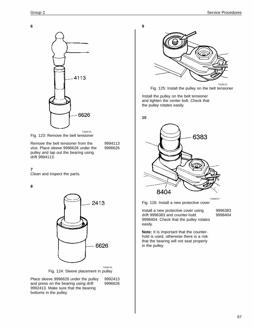
6
T2008725
Fig. 123: Remove the belt tensioner
Remove the belt tensioner from thevice. Place sleeve 9996626 under thepulley and tap out the bearing usingdrift 9994113.
99941139996626
7Clean and inspect the parts.
8
T2008726
Fig. 124: Sleeve placement in pulley
Place sleeve 9996626 under the pulleyand press on the bearing using drift9992413. Make sure that the bearingbottoms in the pulley.
99924139996626
9
T2008724
Fig. 125: Install the pulley on the belt tensioner
Install the pulley on the belt tensionerand tighten the center bolt. Check thatthe pulley rotates easily.
10
T2008727
Fig. 126: Install a new protective cover
Install a new protective cover usingdrift 9996383 and counter-hold9998404. Check that the pulley rotateseasily.
Note: It is important that the counter-hold is used, otherwise there is a riskthat the bearing will not seat properlyin the pulley.
99963839998404
67

Group 2 Service Procedures
Installation
11
T2008346
Fig. 127: Install the belt tensioner
Install the belt tensioner, make surethat the mounting bolt on the tensionercorrectly enters the hole in the timinggear cover. Torque the mounting boltto 24 ± 4 Nm (18 ± 3 ft-lb). Install theprotective cap.
24 ± 4 Nm(18 ± 3 ft-lb)
12
T2008291
Fig. 128: Adjust the belt tensioner
Use a 1/2 in. drive ratchet to move thebelt tensioner to a position that will al-low the fan belt to be installed on itspulleys.
1/2 in. driveratchet
13Check the fan belt, if cracks or chafingmarks are present, replace the fanbelt. Check that the belt is correctlypositioned in the grooves on the pul-leys. Remove the lever from the belttensioner and check fan belt tensionwith Kent-Moore tool J –23600–B.
J–23600–B
2631-06-02-01Viscous Fan, Checking
Before working on a vehicle, set the parking brakes,place the transmission in neutral, and block thewheels. Failure to do so can result in unexpectedvehicle movement and can cause serious personal in-jury or death.
Never work under or around a vehicle unless it is sup-ported on jack stands of adequate rating. Failure touse adequate jack stands can result in the vehiclefalling, which can cause serious injury or death toanyone under the vehicle.
WARNING
HOT ENGINE! Keep yourself and your test equipmentclear of all moving parts or hot engine parts and/orfluids. A hot engine and/or fluids can cause burns orcan permanently damage test equipment.
WARNING
Never remove the cap on the expansion tank whilethe engine is still hot. Wait until the coolant tempera-ture is below 50� C (120� F). Scalding steam and fluidunder pressure may escape and cause serious per-sonal injuries.
WARNING
Do not work near the fan with the engine running. Theengine fan can engage at any time without warning.Anyone near the fan when it turns on could be seri-ously injured. Before turning on the ignition, be surethat no one is near the fan.
WARNING
Always wear eye protection when working around bat-teries to prevent the risk of injury due to contact withsulfuric acid or an explosion.
68

Group 2 Service Procedures
If any of the following characteristics are observed, it ispossible that the fan could be faulty. However, be sure togo through the check list below:
1 The fan does not engage, i.e. low fan speed despitehigh engine load. This will result in high coolanttemperature and thereby a drop in engine output.
2 The fan does not disengage despite low engine load.
Check the following before measuring fan speed:
• That the radiators are not blocked by insects orleaves etc.
• Coolant level is between MIN and MAX.
• Fan drive belt is not loose or cracked.
• The radiator is not blocked by insects or leaves etc.
• The coolant temperature gauge sensor is function-ing properly.
• The cooling system is not blocked.
• The fan is clean and undamaged.
• Fluid has not leaked out of the fan hub.
• The bimetallic spring/plate of the fan is not damagedor blocked.
Note: Operational disturbances concerning the fan canalso be due to wear in the control mechanism.
Note: If the thermostat in the cooling system is faulty,this will also result in faulty fan operation.
Note: The fan drive or clutch is an exchange unit andcannot be repaired since special instruments are re-quired for adjustment and checking of the engagementtemperature and speed.
Note: If fluid has leaked out of the fan drive or clutch, noattempt must be made to refill with silicone fluid since aprecise amount of fluid is required to give the fan itsproperties.
Note: The fan should be stored upright or to a maximumangle of 45�. If the angle is higher or if lying flat on theground, the silicone fluid will drain out of the fan.
2651-03-04-01Charge Air Cooler, Replace-ment(Radiator Removed)
Before working on a vehicle, set the parking brakes,place the transmission in neutral, and block thewheels. Failure to do so can result in unexpectedvehicle movement and can cause serious personal in-jury or death.
WARNING
HOT ENGINE! Keep yourself and your test equipmentclear of all moving parts or hot engine parts and/orfluids. A hot engine and/or fluids can cause burns orcan permanently damage test equipment.
WARNING
Never remove the cap on the expansion tank whilethe engine is still hot. Wait until the coolant tempera-ture is below 50� C (120� F). Scalding steam and fluidunder pressure may escape and cause serious per-sonal injuries.
WARNING
Do not work near the fan with the engine running. Theengine fan can engage at any time without warning.Anyone near the fan when it turns on could be seri-ously injured. Before turning on the ignition, be surethat no one is near the fan.
WARNING
Always wear appropriate eye protection to prevent therisk of eye injury due to contact with engine debris orfluids.
69

Group 2 Service Procedures
Removal1
W2002062
Fig. 129: Remove expansion tank from radiator
Remove the five bolts fastening theexpansion tank to the radiator. Discon-nect the hose from expansion tank tothe radiator top tank. Lift off the ex-pansion tank and set aside.
12 mm socketscrewdriver
2
W2002124
Fig. 130: Remove support brackets
Remove the four bolts holding the twolower air conditioning condenser sup-port brackets to the radiator assembly.
12 mm socket
3
W2002125
Fig. 131: Remove charge air cooler
Remove the remaining bolts fasteningthe charge air cooler to the radiator,and set the charge air cooler aside.
13 mm socket12 mm wrench
4Remove the one bolt holding the over-flow tube to the radiator assembly.
12 mm socket
5
W2002126
Fig. 132: Remove head screws from shroud
Remove the eight torx head screwsfastening the shroud to the radiator,and set the shroud aside.
T 30 torx bit
70

Group 2 Service Procedures
Installation1Install the overflow hose and bracket,the top radiator hose and the bleedhose to the radiator.
7 mm socketscrewdriver
2
W2002126
Fig. 133: Position the shroud into place, install headscrews
Position the shroud into place, installeight torx head screws and handtighten.
T 30 torx bit
3
W2002125
Fig. 134: Install mounting bolts
Position the charge air cooler onto theradiator. Install the four mounting boltsleaving the upper two hand tight.Torque the lower bolts to 24 ± 4 Nm(18 ± 3 ft-lb).
13 mm socket12 mm wrench24 ± 4 Nm(18 ± 3 ft-lb)
4
W2002062
Fig. 135: Install expansion tank bolts
Position the expansion tank into placeand install the five mounting bolts.Torque to 24 ± 4 Nm (18 ± 3 ft-lb).
12mm socket24 ± 4 Nm(18 ± 3 ft-lb)
71

Group 2 Service Procedures
5
W2002102
Fig. 136: Install support brackets
Position the air conditioning condensermounting brackets. Install the fourmounting bolts hand tight.
12 mm socket
3821-06-02-01Coolant Temperature Gauge,Checking
Before working on a vehicle, set the parking brakes,place the transmission in neutral, and block thewheels. Failure to do so can result in unexpectedvehicle movement and can cause serious personal in-jury or death.
WARNING
HOT ENGINE! Keep yourself and your test equipmentclear of all moving parts or hot engine parts and/orfluids. A hot engine and/or fluids can cause burns orcan permanently damage test equipment.
WARNING
Never remove the cap on the expansion tank whilethe engine is still hot. Wait until the coolant tempera-ture is below 50� C (120� F). Scalding steam and fluidunder pressure may escape and cause serious per-sonal injuries.
WARNING
Do not work near the fan with the engine running. Theengine fan can engage at any time without warning.Anyone near the fan when it turns on could be seri-ously injured. Before turning on the ignition, be surethat no one is near the fan.
WARNING
Always wear appropriate eye protection to prevent therisk of eye injury due to contact with engine debris orfluids.
1Remove the temperature sensor fromthe thermostat housing and connectthe electric cable.
2Connect a ground between the tem-perature sensor and the cylinder block.
3Submerse the temperature sensor inheated water.
4Using a thermometer, measure thetemperature. Compare this readingwith the temperature gauge reading.
72

Group 2 Service Procedures
2611-11-04-01Radiator, Cleaning
(Unit Removed)
Before working on a vehicle, set the parking brakes,place the transmission in neutral, and block thewheels. Failure to do so can result in unexpectedvehicle movement and can cause serious personal in-jury or death.
WARNING
HOT ENGINE! Keep yourself and your test equipmentclear of all moving parts or hot engine parts and/orfluids. A hot engine and/or fluids can cause burns orcan permanently damage test equipment.
WARNING
Never remove the cap on the expansion tank whilethe engine is still hot. Wait until the coolant tempera-ture is below 50� C (120� F). Scalding steam and fluidunder pressure may escape and cause serious per-sonal injuries.
WARNING
Do not work near the fan with the engine running. Theengine fan can engage at any time without warning.Anyone near the fan when it turns on could be seri-ously injured. Before turning on the ignition, be surethat no one is near the fan.
WARNING
Always wear appropriate eye protection to prevent therisk of eye injury due to contact with engine debris orfluids.
If you see or suspect that the cell packages of thecharge air cooler or radiator cell packages are dirty,these components should be cleaned. Depending on theinstallation, it may be necessary to completely removethe components from the vehicle; see “Radiator, Re-placement” page 29.
Note: Regardless of cleaning method, extreme cau-tion should be observed so as not to damage theradiator fins.
External Cleaning
1Separate the radiator and the chargeair cooler if they have been removedfrom the vehicle as a single unit. Thisensures proper cleaning of each com-ponent.
2Cover the inlet and outlet pipes to pre-vent degreasing agents or dirt to enter.
3Clean the radiator with compressed airif it is clogged with dust.
Note: Air pressure should not exceed210 kPa (30 psi) for the radiator andshould not exceed 170 kPa (25 psi) forthe condenser.
4When rinsing, start with the back ofthe radiator and then turn it aroundand rinse from the front. Use hot waterand make sure that the cells get clean.
5Gummed up dirt can be removed byusing CALCLEAN cleaners, either inregular or heavy-duty strength. Thesecleaners can be sprayed on the coresusing a hand pump sprayer and rinsedoff. They will not harm the core materi-als.
6In case a degreasing agent is used,be sure to thoroughly clean plastic andrubber parts if these get covered withdegreasing agent.
73

Group 2 Service Procedures
7
W2003373
Fig. 137: Correct positioning of high pressure car wash.
A high pressure car wash with a maxworking pressure of 100–120 bar(1450–1750 psi) may be used, butwith extreme caution. Make sure thatthe nozzle is held perpendicular to cellpackage at all times and that it ismoved from side to side. The nozzleshould always be positioned at a dis-tance of 8–12 inches from the cellpackage.
Note: Using a high pressure carwash will necessitate the removal ofthe radiator(s) from the vehicle inorder to correctly clean the radiatorwithout the risk of damaging thefins with the high pressure.
8Rinse the radiator starting with theback and then turn it around and rinsefrom the front.
2651-11-02-01Charge Air Cooler, Cleaning
Before working on a vehicle, set the parking brakes,place the transmission in neutral, and block thewheels. Failure to do so can result in unexpectedvehicle movement and can cause serious personal in-jury or death.
WARNING
HOT ENGINE! Keep yourself and your test equipmentclear of all moving parts or hot engine parts and/orfluids. A hot engine and/or fluids can cause burns orcan permanently damage test equipment.
WARNING
Never remove the cap on the expansion tank whilethe engine is still hot. Wait until the coolant tempera-ture is below 50� C (120� F). Scalding steam and fluidunder pressure may escape and cause serious per-sonal injuries.
WARNING
Do not work near the fan with the engine running. Theengine fan can engage at any time without warning.Anyone near the fan when it turns on could be seri-ously injured. Before turning on the ignition, be surethat no one is near the fan.
WARNING
Always wear appropriate eye protection to prevent therisk of eye injury due to contact with engine debris orfluids.
1Remove the grille
2Tilt the hood. Support the hood to al-low removal of the safety cables.
74

Group 2 Service Procedures
3
W2000460
Fig. 138: Loosening charge air cooler clamps.
Loosen the charge air cooler clampson the side of the charge air cooler.
4
W2000461
Fig. 139: Unfasten A/C lines
Unfasten the A/C lines from the rightside of the radiator.
5
W2003523
Fig. 140: Removing A/C condenser mounting bolts onVN model
W2003524
Fig. 141: Removing A/C condenser mounting bolts onVHD model
After removing the A/C condenser lineclamps and the A/C condenser mount-ing bolts, the condenser can be laidaside.
Note: All A/C lines on the VN/VHD arelocted on the left side of the coolingpackage. When removing the A/C con-densor line clamps make sure not tolossen the A/C lines.
6Remove the clamps from the chargeair cooler hoses on both sides. Re-move the left side radiator shield.
75
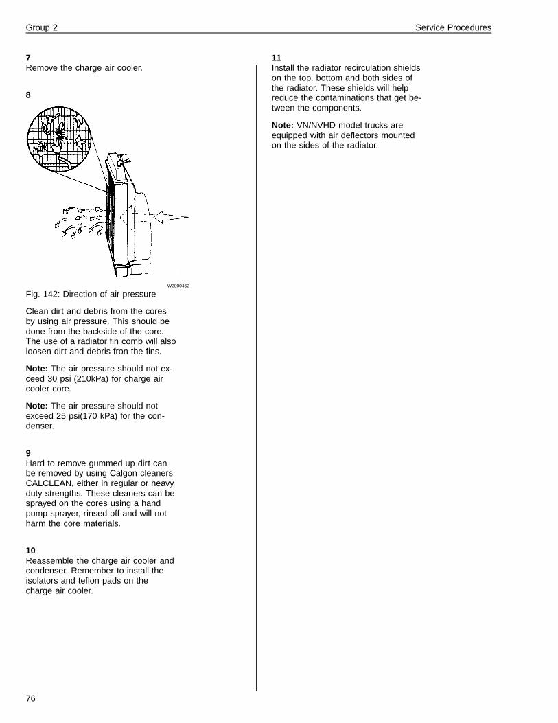
Group 2 Service Procedures
7Remove the charge air cooler.
8
W2000462
Fig. 142: Direction of air pressure
Clean dirt and debris from the coresby using air pressure. This should bedone from the backside of the core.The use of a radiator fin comb will alsoloosen dirt and debris fron the fins.
Note: The air pressure should not ex-ceed 30 psi (210kPa) for charge aircooler core.
Note: The air pressure should notexceed 25 psi(170 kPa) for the con-denser.
9Hard to remove gummed up dirt canbe removed by using Calgon cleanersCALCLEAN, either in regular or heavyduty strengths. These cleaners can besprayed on the cores using a handpump sprayer, rinsed off and will notharm the core materials.
10Reassemble the charge air cooler andcondenser. Remember to install theisolators and teflon pads on thecharge air cooler.
11Install the radiator recirculation shieldson the top, bottom and both sides ofthe radiator. These shields will helpreduce the contaminations that get be-tween the components.
Note: VN/NVHD model trucks areequipped with air deflectors mountedon the sides of the radiator.
76
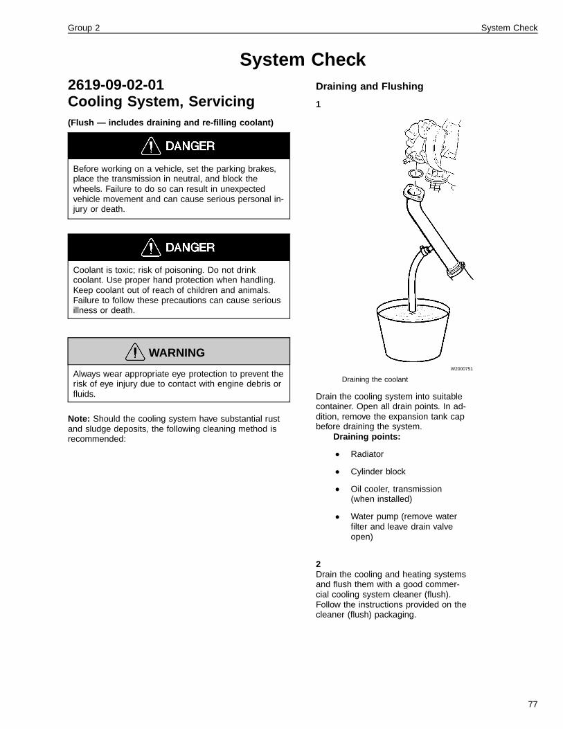
Group 2 System Check
System Check2619-09-02-01Cooling System, Servicing(Flush — includes draining and re-filling coolant)
Before working on a vehicle, set the parking brakes,place the transmission in neutral, and block thewheels. Failure to do so can result in unexpectedvehicle movement and can cause serious personal in-jury or death.
Coolant is toxic; risk of poisoning. Do not drinkcoolant. Use proper hand protection when handling.Keep coolant out of reach of children and animals.Failure to follow these precautions can cause seriousillness or death.
WARNING
Always wear appropriate eye protection to prevent therisk of eye injury due to contact with engine debris orfluids.
Note: Should the cooling system have substantial rustand sludge deposits, the following cleaning method isrecommended:
Draining and Flushing
1
W2000751
Draining the coolant
Drain the cooling system into suitablecontainer. Open all drain points. In ad-dition, remove the expansion tank capbefore draining the system.
Draining points:
• Radiator
• Cylinder block
• Oil cooler, transmission(when installed)
• Water pump (remove waterfilter and leave drain valveopen)
2Drain the cooling and heating systemsand flush them with a good commer-cial cooling system cleaner (flush).Follow the instructions provided on thecleaner (flush) packaging.
77

Group 2 System Check
3Drain the cooling and heating systemsand flush through with clean water. Forquick, efficient draining, remove thelower and upper radiator hoses andthe drain valves. Do not forget to drainthe heater element and the engineheater.
4Run the engine for 10–15 minutes atnormal working temperature and thenrepeat the flushing procedure.
5The heating system must be flushedseparately with hoses disconnected toensure removal of any impurities left inthe system. Also remove the expan-sion tank cap. For effective cleaning,flush the expansion tank from belowwith the cap removed.
6When the system is entirely free fromimpurities, it is ready to be refilled withnew coolant, seetable page 17
7If the system is cleaned on a regularbasis (for example, when the concen-trated coolant is drained or filled) orwhen the system is relatively free fromdeposits, a smaller amount of cleaneradditive or simply flushing with cleanwater may be sufficient.
Note: Chemicals for cleaning the cool-ing system are not marketed by VolvoTrucks North America and must be ob-tained elsewhere. Dispose of allcleaner’s and coolant fluids accordingto local and state regulations.
Filling
8The cooling system is filled throughthe expansion tank. The engine mustbe switched off and the heater controlsset at WARM.
9Fill with coolant to the maximum levelon the expansion tank. The coolingsystem will vent itself automatically.
10Place shift lever in neutral and applyparking brake.
11After running the engine warm andthen allowing it to cool, check thecoolant level again.
78

Feedback
One of our objectives is that workshop personnel should have access to correct andappropriate service manuals where it concerns fault tracing, repairs and maintenanceof Volvo trucks.In order to maintain the high standards of our literature, your opinions and experiencewhen using this manual would be greatly appreciated.If you have any comments or suggestions, make a copy of this page, write down yourcomments and send them to us, either via telefax or mailing directly to the addresslisted below.
To
Volvo Trucks North America, Inc.
Dept. 516 Service Publications
7825 National Service Road
P.O. Box 26115
Greensboro, NC 27402-6115
USA
Fax (336) 393-3170
From
..........................................................................
..........................................................................
..........................................................................
..........................................................................
..........................................................................
..........................................................................
..........................................................................
Comments/proposals
................................................................................................................................................................................
................................................................................................................................................................................
................................................................................................................................................................................
................................................................................................................................................................................
................................................................................................................................................................................
................................................................................................................................................................................
................................................................................................................................................................................
................................................................................................................................................................................
................................................................................................................................................................................
................................................................................................................................................................................
................................................................................................................................................................................
................................................................................................................................................................................
................................................................................................................................................................................
Concerns Service Manual: ...............................................................................................................................


Operation Numbers
2611-03-02-01 Radiator, Replacement . . . . . . . . . . . . . . . . . . . . . . . . . . . . . 292611-06-02-01 Radiator, Checking . . . . . . . . . . . . . . . . . . . . . . . . . . . . . . . 382611-11-04-01 Radiator, Cleaning . . . . . . . . . . . . . . . . . . . . . . . . . . . . . . . 732612-03-02-01 Radiator Surge Tank, Replacement . . . . . . . . . . . . . . . . . . . . . . . 382619-06-02-01 Cooling System Leak Test, Checking . . . . . . . . . . . . . . . . . . . . . . . 412619-09-02-01 Cooling System, Servicing . . . . . . . . . . . . . . . . . . . . . . . . . . . . 772621-03-02-01 Coolant Pump, Replacement . . . . . . . . . . . . . . . . . . . . . . . . . . 432621-04-04-01 Coolant Pump, Overhaul . . . . . . . . . . . . . . . . . . . . . . . . . . . . 482627-03-02-01 Thermostat, Replacement . . . . . . . . . . . . . . . . . . . . . . . . . . 55, 592627-06-05-01 Thermostat, Checking . . . . . . . . . . . . . . . . . . . . . . . . . . . . . . 612631-03-02-01 Viscous Fan, Replacement . . . . . . . . . . . . . . . . . . . . . . . . . . . 612631-06-02-01 Viscous Fan, Checking . . . . . . . . . . . . . . . . . . . . . . . . . . . . . 682634-03-02-01 Fan Belt Tensioner, Replacement . . . . . . . . . . . . . . . . . . . . . . . . 632634-03-02-04 Cooling Fan Drive Belt, Replacement . . . . . . . . . . . . . . . . . . . . . . 652634-04-02-01 Fan Belt Tensioner, Overhaul . . . . . . . . . . . . . . . . . . . . . . . . . . 652651-03-04-01 Charge Air Cooler, Replacement . . . . . . . . . . . . . . . . . . . . . . . . . 692651-11-02-01 Charge Air Cooler, Cleaning . . . . . . . . . . . . . . . . . . . . . . . . . . . 743821-06-02-01 Coolant Temperature Gauge, Checking . . . . . . . . . . . . . . . . . . . . . . 72

Volvo Trucks North America, Inc.P.O. Box 26115, Greensboro, NC 27402-6115
Volvo Trucks Canada, Ltd.6490 Vipond Drive, Mississauga, Ontario L5T 1W8
http://www.volvotrucks.volvo.com
PV776-TSP142854 (1000) 8,2000 © Volvo Trucks North America, Inc., 2000


