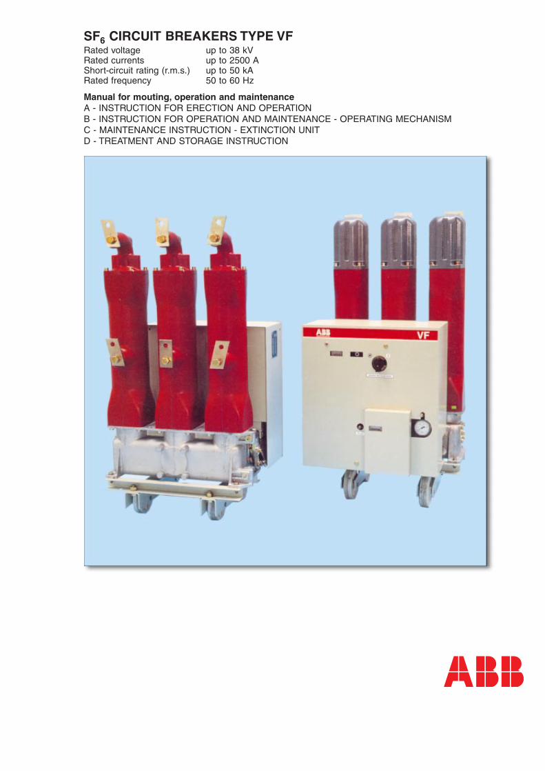
SF6 CIRCUIT BREAKERS TYPE VFRated voltage up to 38 kV Rated currents up to 2500 A Short-circuit rating (r.m.s.) up to 50 kA Rated frequency 50 to 60 Hz
Manual for mouting, operation and maintenance A - INSTRUCTION FOR ERECTION AND OPERATION B - INSTRUCTION FOR OPERATION AND MAINTENANCE - OPERATING MECHANISM C - MAINTENANCE INSTRUCTION - EXTINCTION UNIT D - TREATMENT AND STORAGE INSTRUCTION

3
4
A.1 GENERAL
5
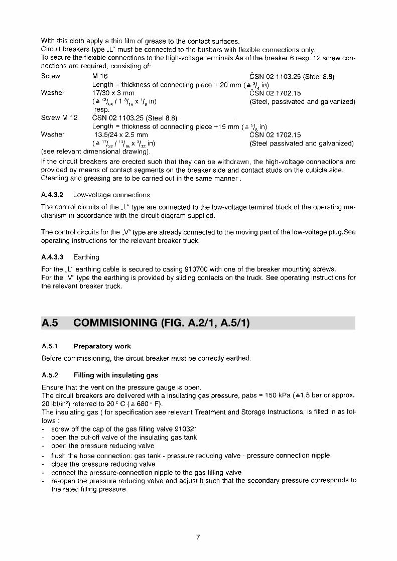
A.2 CONSTRUCTION (FIG.A.2/1)
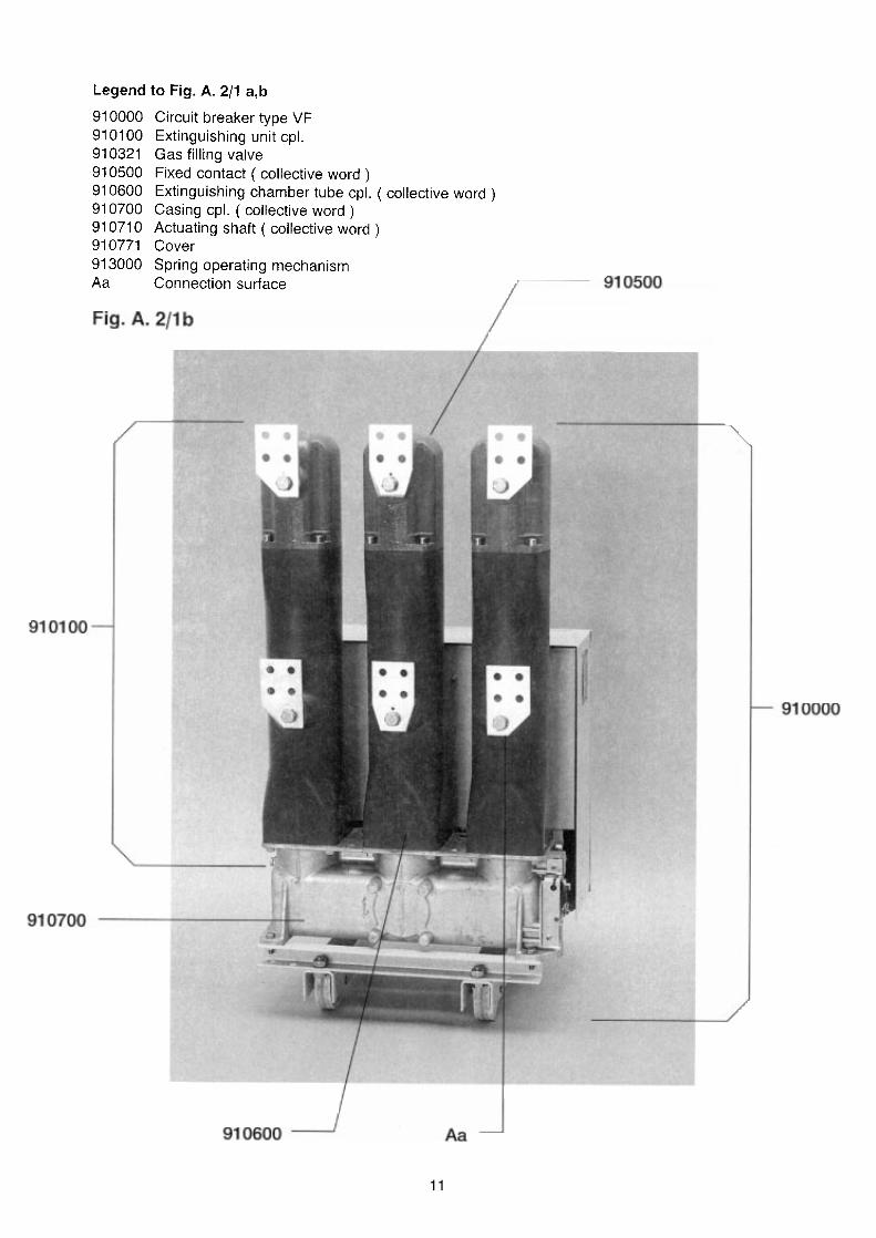
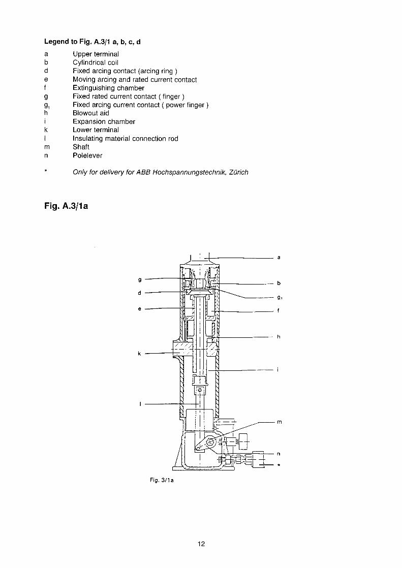
A.3 FUNCTION (FIG.A.3/1)

6
A.4 ERECTION (FIG.A.4/1)
7
A.5 COMMISIONING (FIG. A.2/1, A.5/1)

8

9
A.7 MAINTENANCE

9/2
Diagnostic of circuit breaker insulating state and state of SF6 gas filling
This diagnostic is carried out in reference to the current stress according to Fig. A.7.1, but at least onceafter 5 years. The procedures are as follows:
A/ Measurement of the leakage current at DC voltage of 25 kV with a shielded conductor
Prescribed parameters of testing equipment:
High voltage source – min. 25 kV DC – which makes possible to perform the measurement in a shieldedmode Accuracy: 2 %Resolution: ≤ 20 nA
a) - If the leakage current on each of three insulating draw rods of circuit breaker is lower or equal to 0.1 µA, the circuit breaker is applicable to further secure operation.
a) - If the leakage current on the insulating draw rod of any phase is high than 0.1 µA, all insulatingrods must be dismounted and replaced and further prescribed activities are to be performed according to sect. C.7.1.1.
b) - If the leakage current on each of three quenching chambers of circuit breaker is lower or equal to 1 µA, the circuit breaker is applicable to further secure operation.
b) - If the leakage current on any quenching chamber is high than 1 µA, this quenching chambermust be dismounted and replaced and further prescribed activities are to be performed according to sect. C.7.1.1.
a) Test of the insulating draw rod (lower terminal against case)
b) Test of the quenching chamber(upper terminal against lower terminal)
High voltage - DC 25 kV High voltage - DC 25 kV
Measuring equipmentwith HV power source
Measuring equipmentwith HV power source
Return conductor
Return conductor
Shielding ShieldingEarthing point
Earthing
Earthing point
Earthing
Circuit breaker case must be insulated against earth potential
Circuit breaker case must be insulated against earth potential

9/3
B/ Measurement of gas filling purity – of SF6 content in volume percentage
The measurement is carried out according to manual and instructions of manufacturer usedmeasuring equipment.
Prescribed parameters of testing equipment:
The apparatus for measurement of SF6 volume percentage content in a mixture of gases Measurement range: 0 ÷ 100 % of contentInlet pressure: 0.17 ÷ 1 MPaMeasurement accuracy: ±1 % of SF6 from the mixture content of gases
- If the measured value in the gas filling of circuit breaker is equal or higher than 97 volume percentageof SF6, the circuit breaker is applicable to further secure operation.
- If the measured value in the gas filling of circuit breaker is lower than 97 volume percentage of SF6,the gas filling must be replaced by a new one.
C/ Measurement of SF6 gas filling moisture – of dew point in centigrade degrees
The measurement is carried out according to manual and instructions of manufacturer used measuringequipment. The measurement is performed in relation to the atmospheric pressure of measured gas.
Prescribed parameters of testing equipment:
The apparatus for measurement of SF6 gas dew point in relation to the atmospheric pressure ofmeasured gas – the dew point is determined independently of pressure in the gas compartment.Measurement range: to – 55 °C at ambient temperature of 20 °CMeasurement accuracy: ≤ ± 0.2 °C Inlet pressure: 1 kPa ÷ 1 MPa
- If the measured dew point of gas filling is lower or equal to – 30 °C in relation to atmospheric pressureof measured gas, the circuit breaker is applicable to further secure operation.
- If the measured dew point of gas filling is higher than – 30 °C in relation to atmospheric pressure ofmeasured gas, the gas filling must be replaced by a new one.

10
A.11 APPENDIX
11
12
13
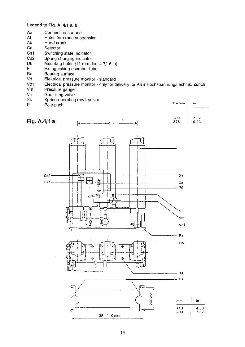
14

15
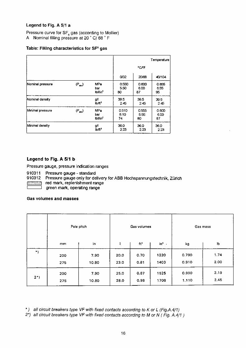
16
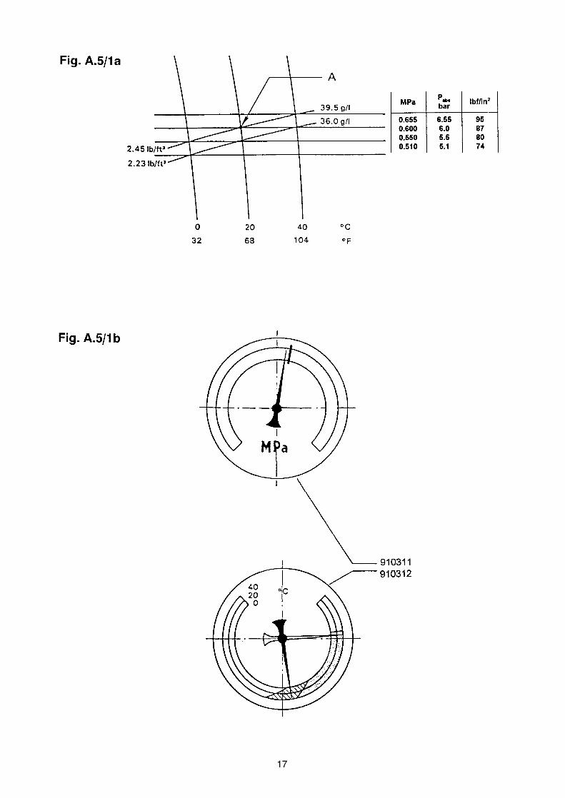
17

18
Example:A circuit breaker type VF 12.12.16 has performed 3500 breakings at current of 1250 A and two breakingsof the rated breaking current of 20 kA at the rated voltage 7.2 kV. Now, we should determine how manybreakings at 1250 A could be performed before reaching the permissible sum current limit of contactloading. According to the curve 4500 breakings at 1250 A and 15 breakings at 20 kA can be carried out.It is then: N 1.25 = 4500
N 20 = 15n 1.25 = 3500n 20 = 2
The set up equation:n 1.25 n 20 x
————- + ——— + ———- = 1N 1.25 N 20 N 1.25
n 1.25 n 20x = ( 1 - ———— - ——— ) . N 1.25
N 1.25 N 20
3500 2 x = ( 1 - ———— - ——— ) . 4500
4500 15
x = 400
According to this calculation the given circuit breaker can perform further 400 breakings at current 1250A to the end of its revision-free service life.
Legend to Fig. A.7/1
n Number of switching operationslk Breaking current in A
In rated current range cos ϕ ≅ 0,8In short-circuit current range cos ϕ ≅ 0,1
Fig. A.7/1

19
20
B.1 GENERAL
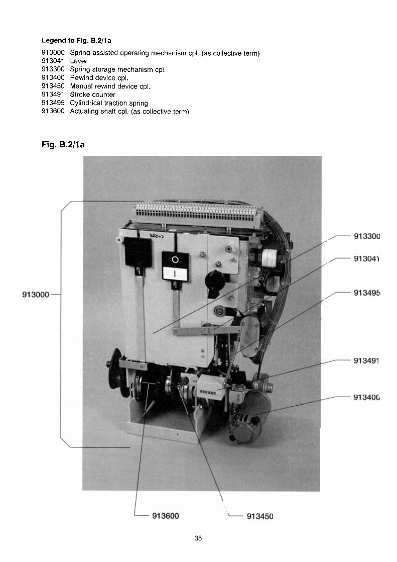
B.2 CONSTRUCTION (FIG. B.2/1)
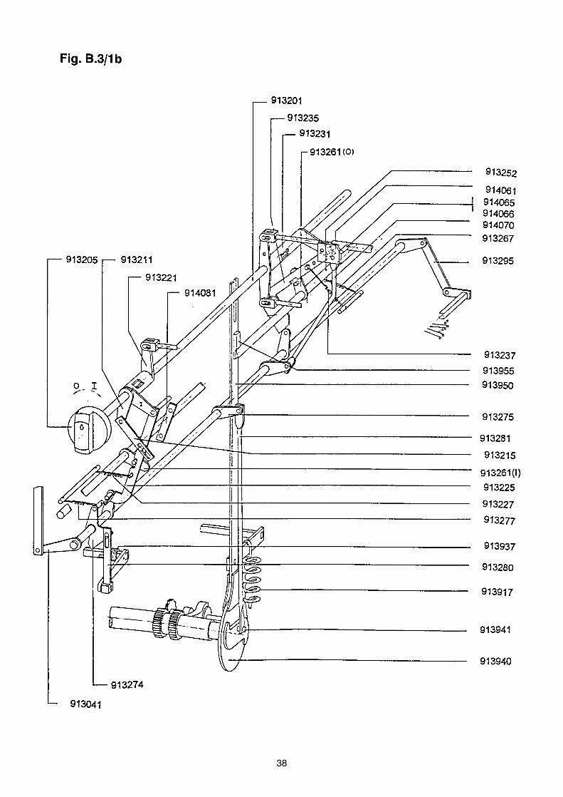
B.3 FUNCTION (FIG. B.3/1 A,B,C)

21

22
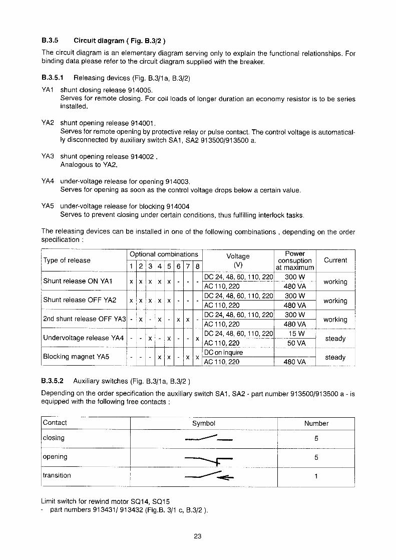
23

24
B.7 MAINTENANCE

25
26
27
28

29

30
B.8 SPARE PARTS

31

32
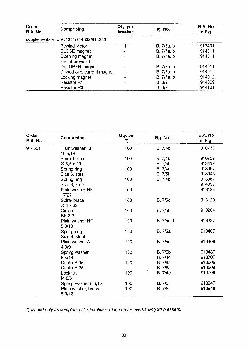
33
34
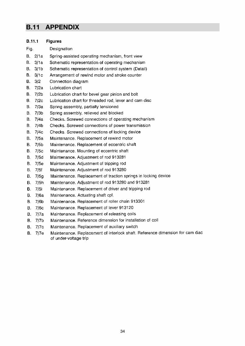
B.11 APPENDIX
35

36

37
38

39

40
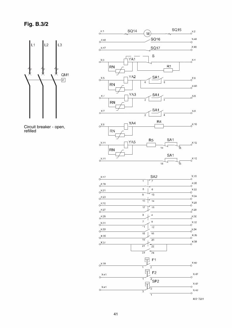
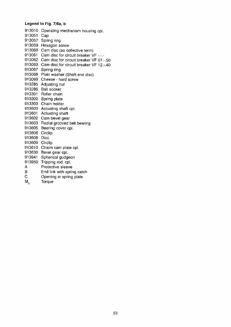
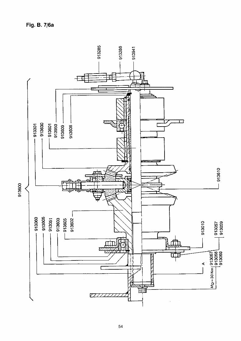
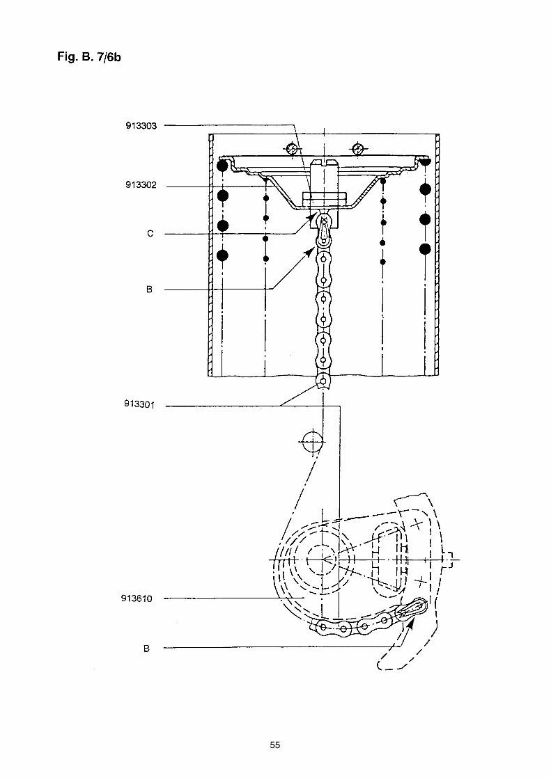
Legend to Fig. B. 3/2
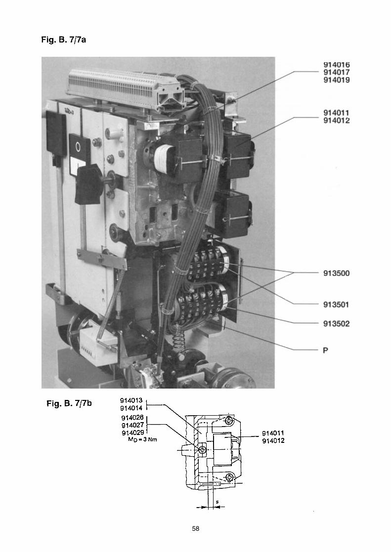
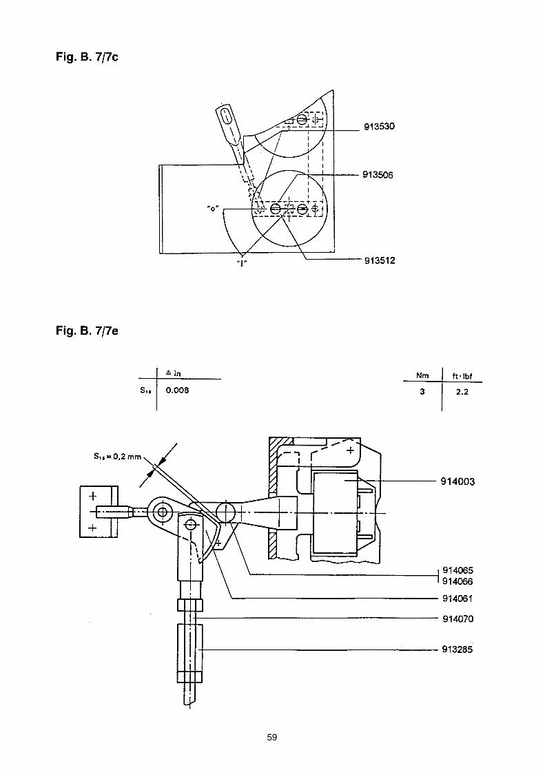
Connection diagram910000/910500 QM1 Circuit breaker913331 SP2 Pressure monitor or F1, F2 density monitor, 2 steps913401 M Charging motor913500 S1 Auxiliary switch SA1, SA2914005 YA1 Closing release914001 YA2 Shunt opening release914002 YA3 Second shunt opening reiease914003 YA4 Under - voltage release for opening914004 YA5 Under - voltage release for blocking914009 R1 Resistor for YA1914131 R4 Resistor for YA4913503 S Auxiliary contact for YA1913504 X Multipole terminal913431 SQ14 End switch of charging motor913432 SQ15 End switch of charging motor914999 R5 Resistor for YA5995555 SQ16*)995556 SQ17*)995557 F1*)
RN Varistor - is not a standart part of the circuit breaker electrical equipment
*) Only for delivery for ABB Hochspannungstechnik, Zurich
41
Schéma zapojení
Circuit breaker - open,refilled
Fig. B.3/2
42
43
44

45
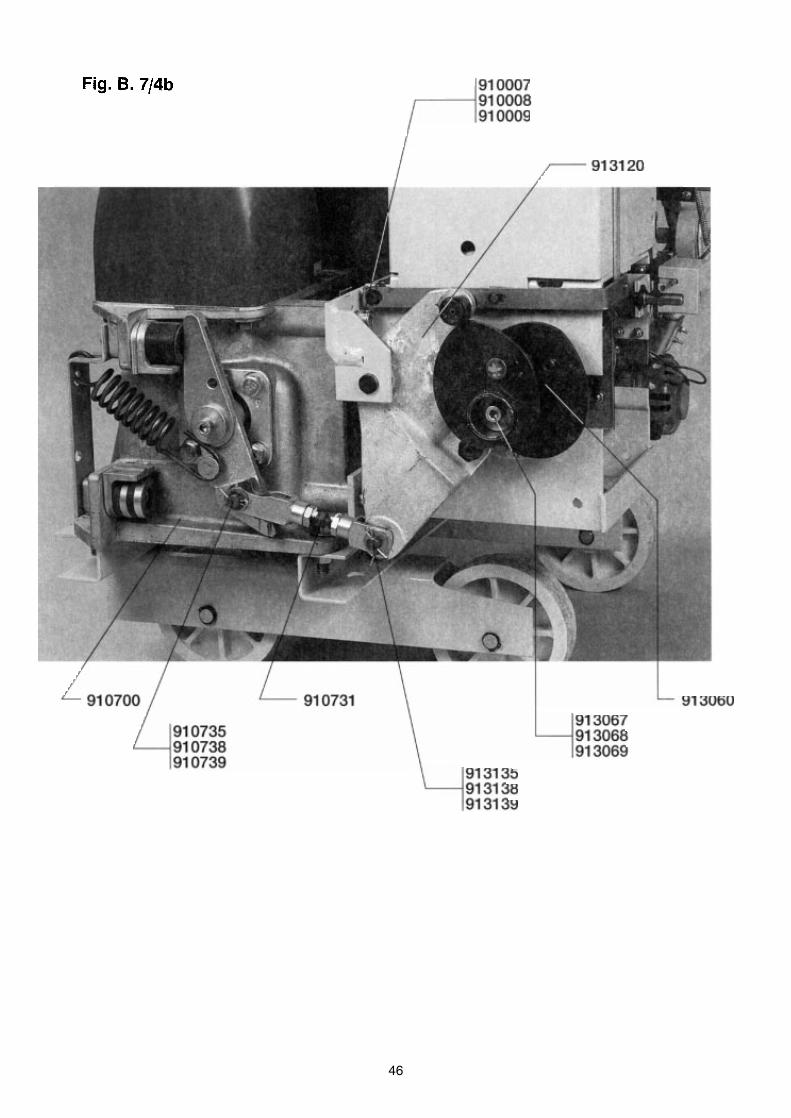
46
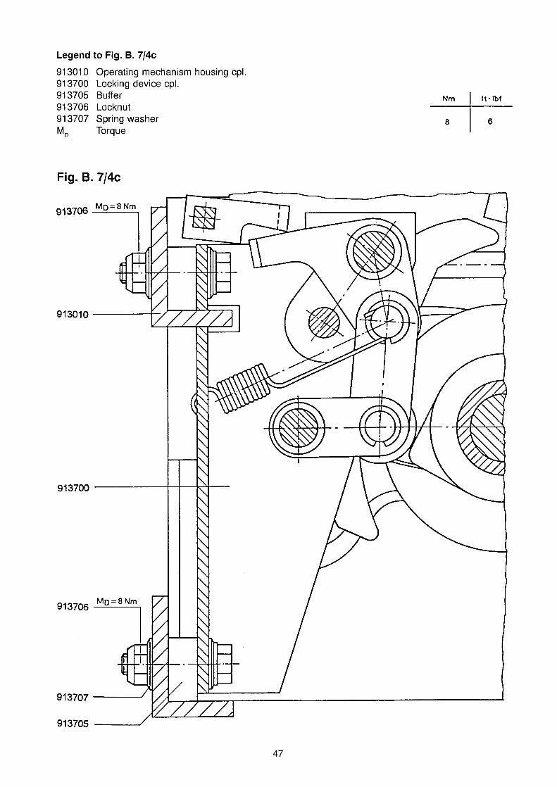
47

48

49

50
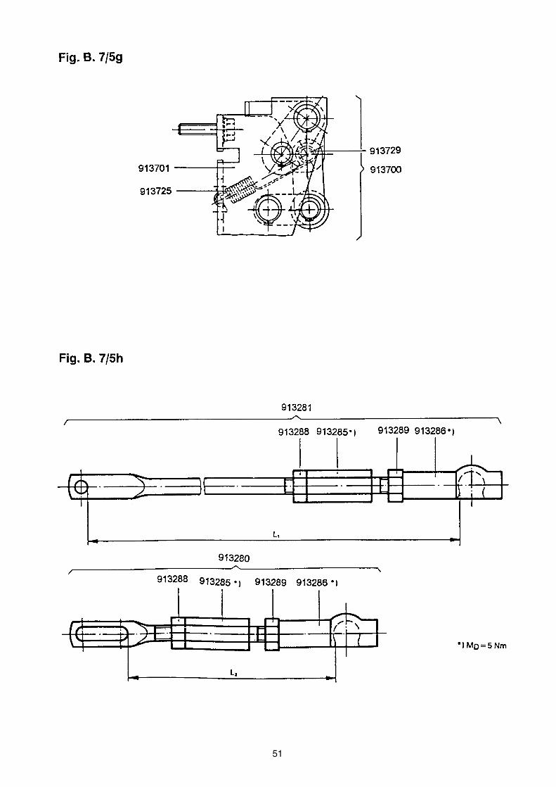
51
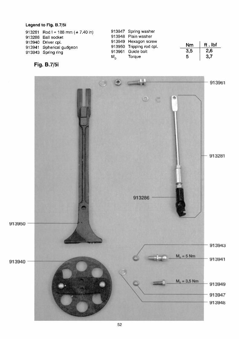
52
53
54
55

56
57
58
59

60
61
C.1 GENERAL
C.2 CONSTRUCTION (FIG. C.2/1)

62
C.7 MAINTENANCE

63
64
65
66
67
68
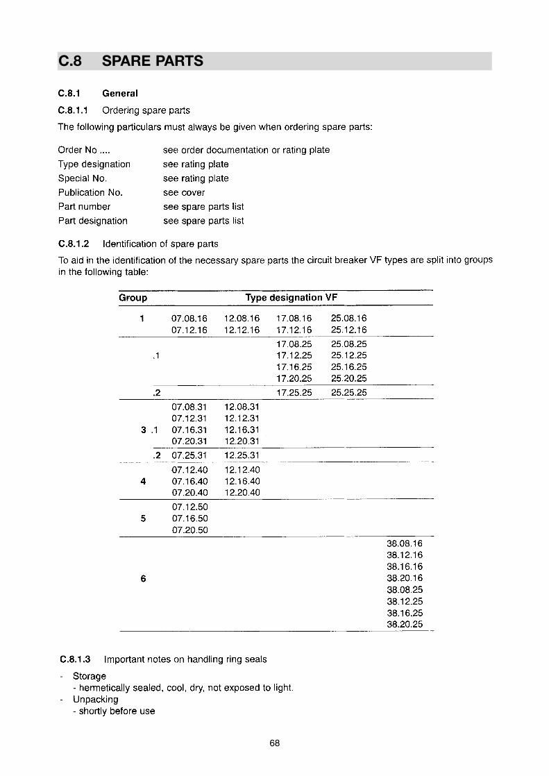
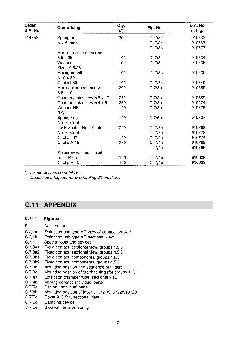
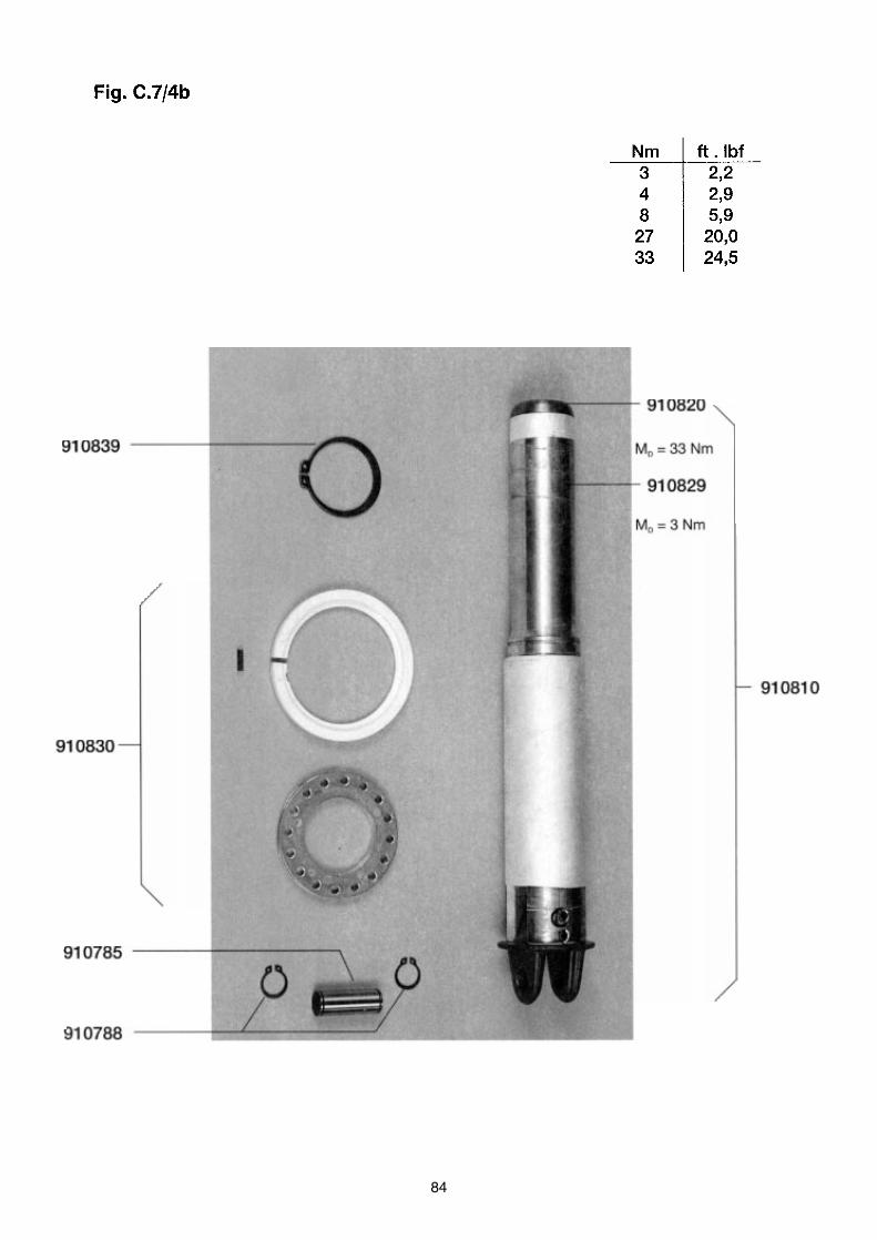
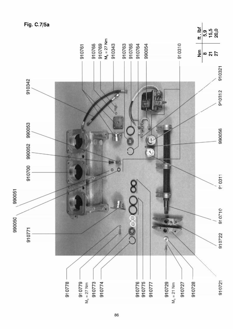
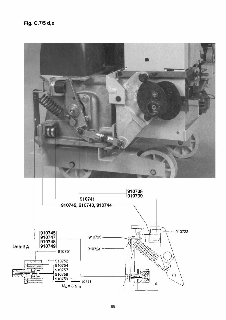
C.8 SPARE PARTS
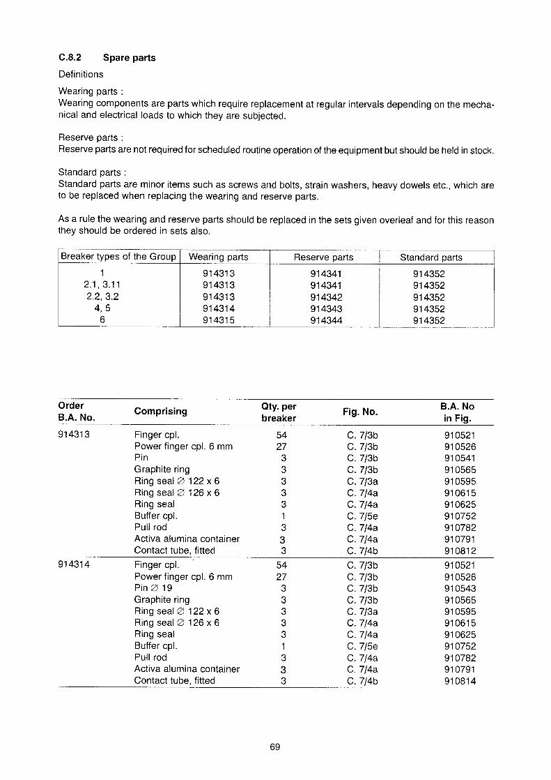
69

70
71
C.11 APPENDIX
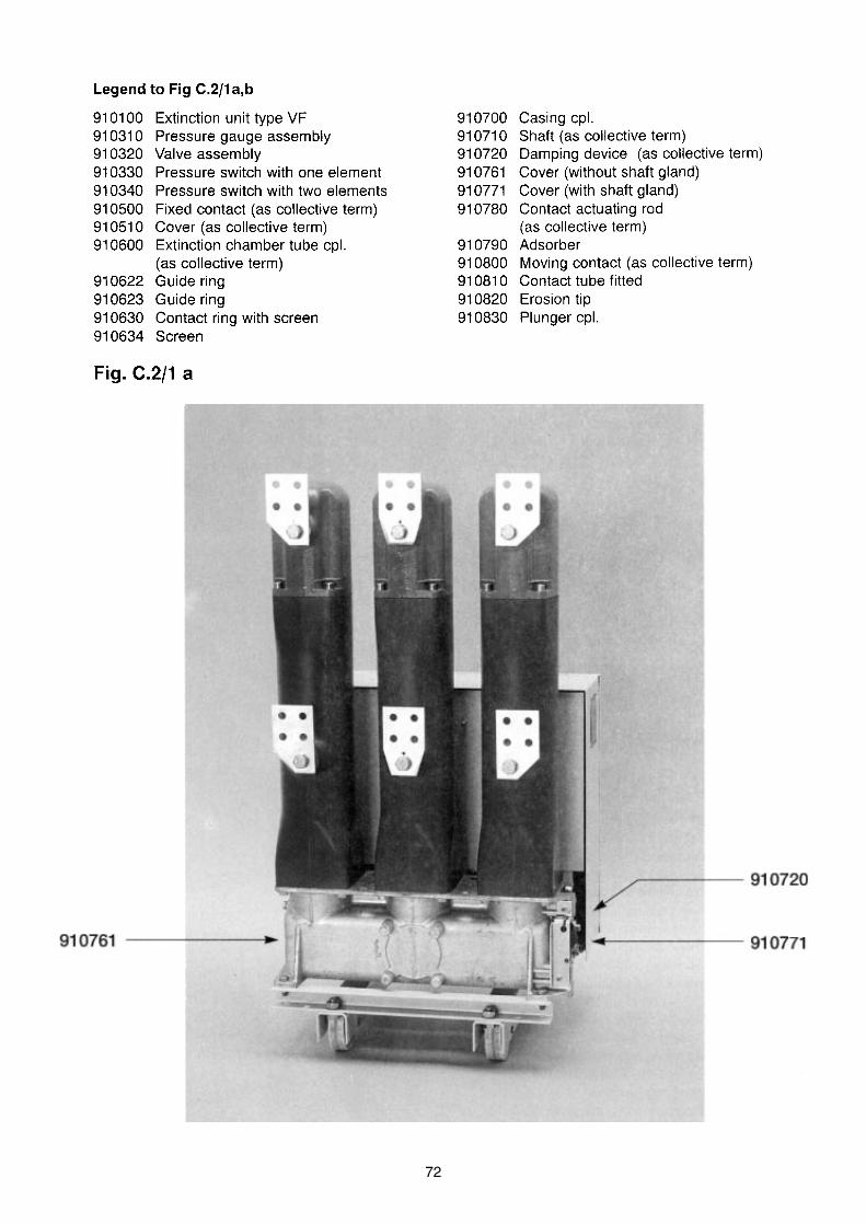
72
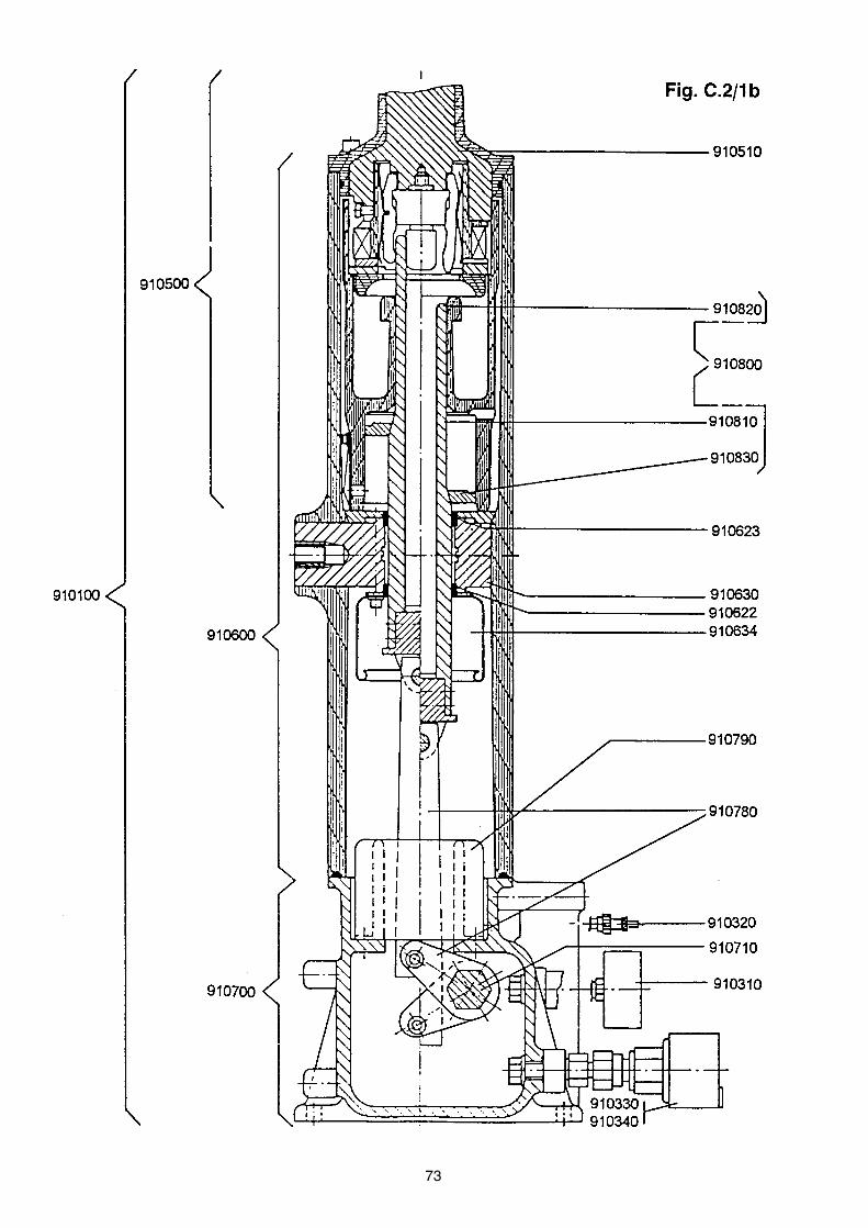
73

74

75

76

77
78

79
80

81
82
83
84

85
86

87
88
89
90
D.1 GENERAL
91
92
D.2 LUBRICANTS
93
D.4 BONDING AGENTS
94
D.5 GAS LEAKAGE TESTS
95
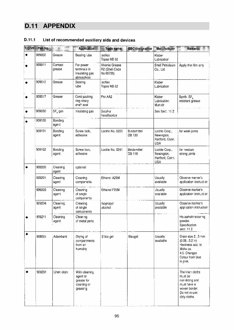
D.11 APPENDIX
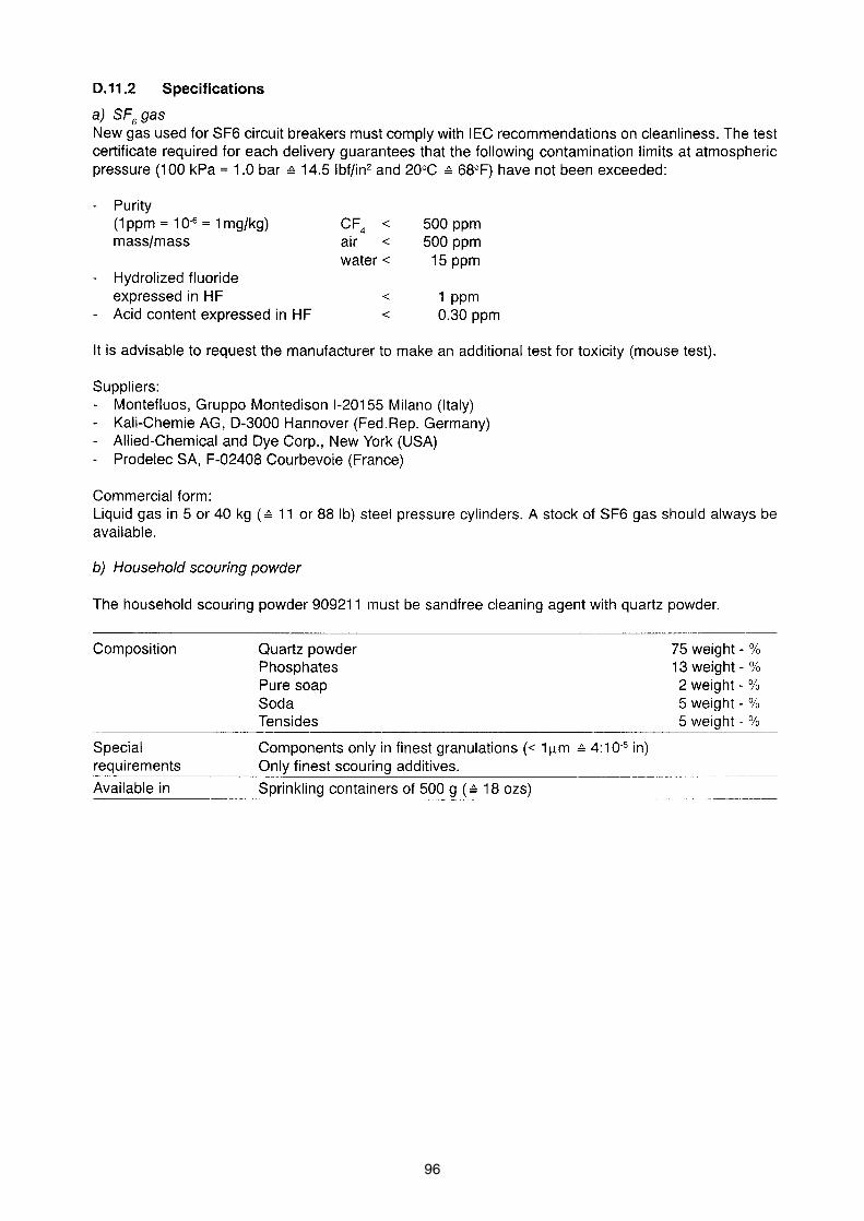
96
97
D.21 GENERAL
D.22 RECEIPT
D.23 STORAGE
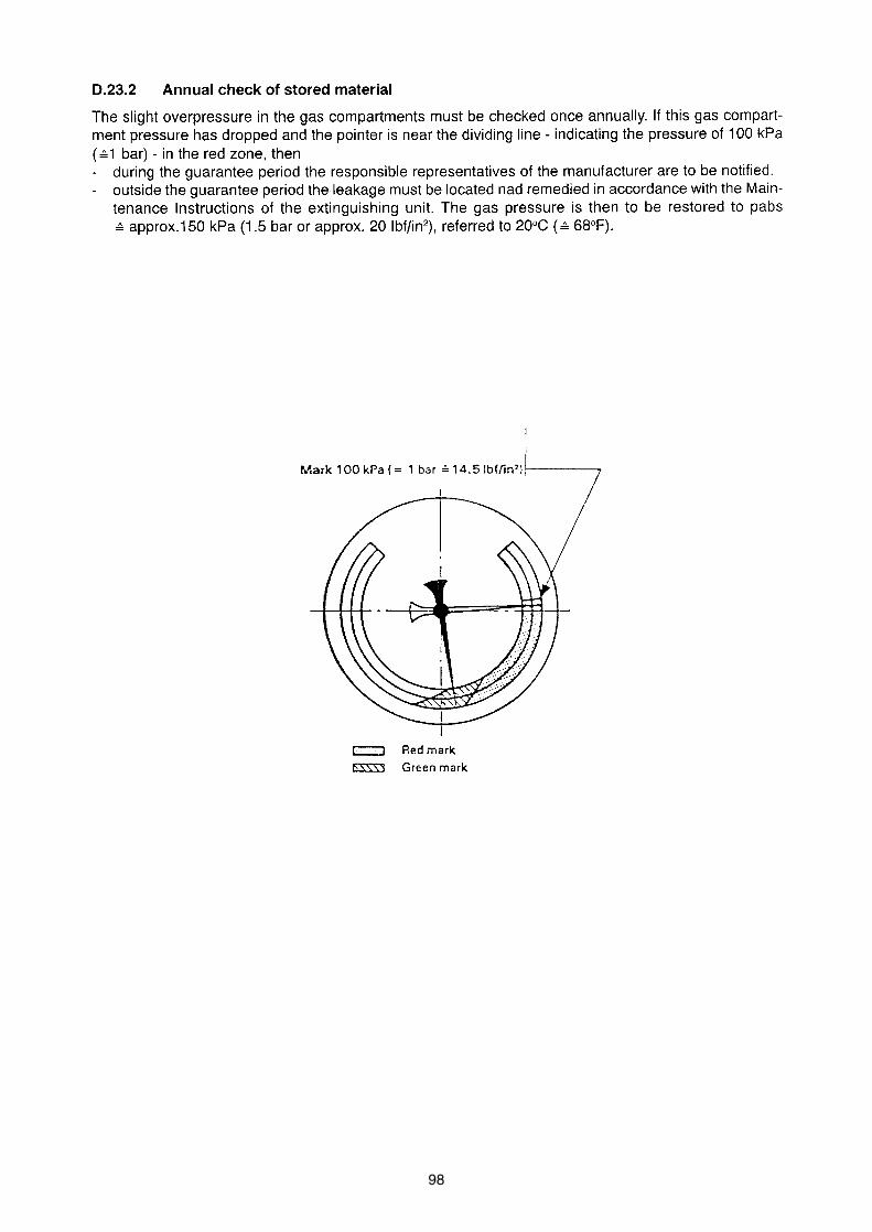
98
ABB s.r.o.org.unit EJF Tel.: +420 5 4715 2413Vídeňská 117 +420 5 4715 2175619 00 Brno +420 5 4715 2465Czech Republic Fax: +420 5 4715 2190http://www.abb.com +420 5 4721 3139E-mail: [email protected]
A 3
58-1
78-I
I/20
01M
![Vacuum Circuit Breakers - Fuji · PDF fileFuji Vacuum Circuit Breaker ... Compact, light-mass design Vacuum circuit breakers have a small switching stroke as ... [kV] 3.6/7.2 Rated](https://cdn.vdocuments.net/doc/165x107/5a89cdba7f8b9a7f398b63c5/vacuum-circuit-breakers-fuji-vacuum-circuit-breaker-compact-light-mass-design.jpg)


