
Profile shots on heavy wall pipes with digital radiography (CR/DR) and portable betatrons
Dennis Zaal
GE’s 11th X‐Ray Forum in Cologne, July 7th – July 9th 2015

IRM Systems
Introduction
Parties involved
Equipment
Test samples
Test setup
Results
Questions
Contents

specialized in inspection, repair and maintenance. Pipeline owners bring inIRM Systems when:
• Looking to minimize overall downtime on their critical lines, includingunplanned repairs
• Frustrated that inspection, repair and maintenance costs are eating intoa business case
• Searching for independent, impartial advice and field engineering onintegrity (procedures, prices etc.)
IRM Systems is a pipeline engineering firm
Services we provide – engineering, design, project management, andtechnical advisory services on pipeline integrity: from pre‐commissioningto end‐of‐life.

Interest raised by Total E&P NL to perform digital profile radiography onbigger diameter and heavy wall pipes
This by use of a portable 2.5 MeV betatron to replace Co‐60
09 & 10th December 2014 tests at JME
Introduction

• JME Provision of the portable betatron and bunker facilities
James Denton
• GE Provision and operation of digital radiography equipment
Stephen Alderton
• Klift Manufacturing of test samples and shipment
Peter van der Klift
• Total Client and witnessing of tests
Bas Vrijbergen
• Applus RTD NDT company
Martijn Hol, Henri van Bavel
• IRM Systems Managing project and radiography expertise
Dennis Zaal
Parties involved

Equipment: JME 2.5 MeV Betatron

Equipment: JME 7.5 MeV Betatron

Equipment: GE DR panel DXR250U‐W and CRxVision
Panel GE DXR250U‐W GE CRxVision
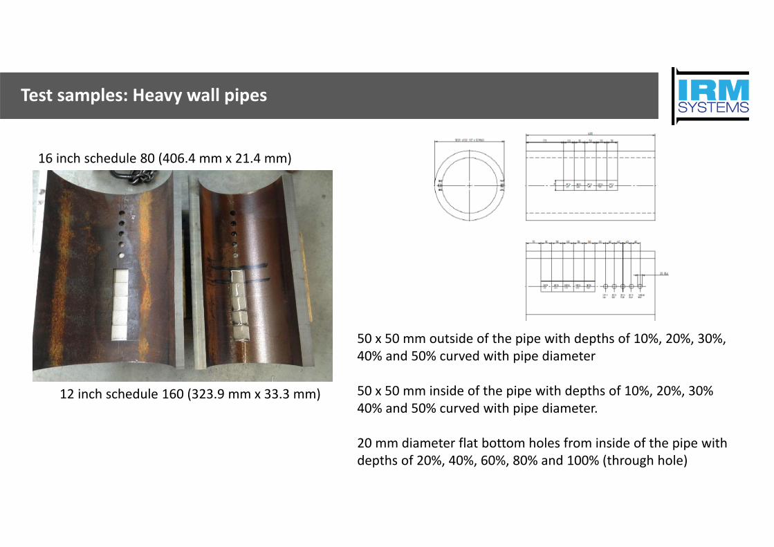
Test samples: Heavy wall pipes
12 inch schedule 160 (323.9 mm x 33.3 mm)
16 inch schedule 80 (406.4 mm x 21.4 mm)
50 x 50 mm outside of the pipe with depths of 10%, 20%, 30%, 40% and 50% curved with pipe diameter
50 x 50 mm inside of the pipe with depths of 10%, 20%, 30% 40% and 50% curved with pipe diameter.
20 mm diameter flat bottom holes from inside of the pipe with depths of 20%, 40%, 60%, 80% and 100% (through hole)

Maximum penetrated thickness
Wmax for 12 inch schedule 160 (323,9 mm x 33,3 mm) is 197 mmWmax for 16 inch schedule 80 (406,4 mm x 21,4 mm) is 182 mm
Maximum penetrated thickness of the 2.5 MeV betatron and Co‐60 is ~120 mm of steelMaximum penetrated thickness of the 7.5 MeV betatron is ~200 mm of steel
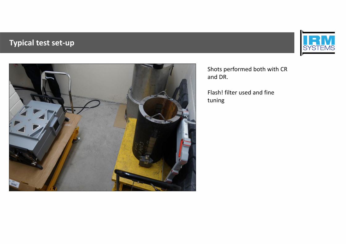
Typical test set‐up
Shots performed both with CR and DR.
Flash! filter used and fine tuning

12 inch schedule 160 tests results: 2.5 MeV
12 inch schedule 160 outside steps 2.5 MeV DR panel (4 frames 120 s)
12 inch schedule 160 inside steps 2.5 MeV CR (1200 s) 12 inch schedule 160 inside holes 2.5 MeV DR panel (1 frame 120 s)

12 inch schedule 160 tests results: 7.5 MeV12 inch schedule 160 inside inside steps 7.5 MeV DR panel (4 frames 30 s)

16 inch schedule 80 tests results
16 inch schedule 80 inner steps 2.5 MeV DR panel (4 frames 60 s) 16 inch schedule 80 inner steps and holes 2.5 MeV CR (600 s)
16 inch schedule 80 outside steps 2.5 MeV DR panel (4 frames 60 s)

Pipe in pipe: 7.5 MeV
Pipe in pipe 12 inch pipe inside 16 inch with 12 inch outside steps 7.5 MeV DR panel (4 frames 30 s)

Pipe in pipe: 7.5 MeV
Pipe in pipe 12 inch pipe inside 16 inch with 12 inch inside steps 7.5 MeV DR panel (4 frames 30 s)

12 JME sample WT ~17 mm
6 inch JME piece with WT ~17 mm: 2.5 MeV DR panel (4 frames 60 s)Penetrated thickness ~102 mm

12 JME sample WT ~16.5 mm
12 inch JME piece 2.5 MeV DR panel (4 frames 60 s)Penetrated thickness ~143 mm

Radiation Safety: Barrier distance

Radiation Safety: Absorbtion material

Conclusion and recommendations
Conclusion• Good image quality with portable betatrons
2.5 MeV• 120 mm penetrated thickness is good reference for 2.5 MeV for profile radiography• Barrier of ~100 meters or >150 mm lead is not feasible for offshore platforms
7.5 MeV• 200 mm penetrated thickness was able to penetrate pipe in pipe situations• Too heavy for offshore purposes• Ideal for specific projects
CR and DR• Difference in image quality of the CR and DR systems was hardly visible.• DR 10 times faster then CR
Recommendations• For heavy wall pipes recommendation is contact shots and C‐scan • Perform tests with Co‐60 for comparisation

www.irm‐sys.comMaerten Trompstraat 252628 RC DelftThe NetherlandsOffice: +31 15 202 3006Cell: +31 61 318 6319d.zaal@irm‐sys.com


