Computer-Aided Design 38 (2006) 1224–1232www.elsevier.com/locate/cad
Skewed rotational symmetry detection from a 2D line drawing of a 3Dpolyhedral object
H.L. Zou, Y.T. Lee∗
School of Mechanical and Aerospace Engineering, Nanyang Technological University, Nanyang Avenue, Singapore 639798, Singapore
Received 17 May 2006; accepted 24 August 2006
Abstract
This paper introduces a new algorithm for detecting skewed rotational symmetry in a 2D line drawing of a 3D polyhedral object by locatingthe possibly-multiple symmetry axes. The drawing is converted into an edge–vertex graph from which the algorithm finds the faces of the objectand the sets of topologically symmetric edges and vertices. It then checks that each set of vertices is rotationally symmetric geometrically byanalyzing the distribution of the vertices around the circumference of the best-fit ellipse. The object is rotationally skewed symmetric if the bestfit ellipses of all the vertex sets have parallel axes, equal ratio of major radius to minor radius and centers on the axis of rotation. A tolerance isused in the calculation to allow for inaccuracies in the line drawings. A set of experimental results is presented showing that the algorithm workswell.c© 2006 Elsevier Ltd. All rights reserved.
Keywords: Computer-aided conceptual design; Skewed rotational symmetry; Line drawing; Sketching; Ellipse fitting
1. Introduction
Symmetry exists in many physical objects, natural and man-made. Symmetry helps humans to recognize and interpretthese objects. Symmetry analysis of images and drawings hasmany applications, especially in computer vision, artificialintelligence and related fields. One recent application isin computer-aided conceptual design, whereby a designersketches a design in 2D, and a 3D model is recoveredautomatically from the sketch. Many attributes, such as thefaces of the object, parallel edges and symmetry, need tobe identified from the sketch and used as constraints inthe algorithm for recovering the 3D object [1]. Furthermore,symmetry information is also useful in ‘beautifying’ the objectrecovered, so as to produce a properly dimensioned solid modelthat can be used in a CAD system [2].
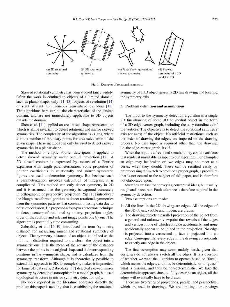
Most research on symmetry has been concerned with mirrorand rotational symmetry [3–7]. Our work on mirror symmetryhas been published elsewhere [8]. In this paper, we concentrateon rotational symmetry. Fig. 1 illustrates the three classes ofrotational symmetry: planar, spatial and skewed.
∗ Corresponding author. Tel.: +65 67905493; fax: +65 7924062.E-mail addresses: [email protected] (H.L. Zou),
[email protected] (Y.T. Lee).
0010-4485/$ - see front matter c© 2006 Elsevier Ltd. All rights reserved.doi:10.1016/j.cad.2006.08.003
Skewed symmetry, as defined by Kanade [9], depicts realsymmetry viewed from some (unknown) viewing direction. Aface showing skewed symmetry in 2D is a planar projectionof a truly symmetric face in 3D. Fig. 1(c) shows some skewedrotational symmetric faces after projection. A skewed spatialsymmetry denotes a truly rotationally symmetric model in 3D(Fig. 1(d)).
In this paper, we present a novel method for detecting theskewed rotational symmetry of a 3D object from its 2D linedrawing. The next section reviews the related work, followedby the problem definition and assumptions. Subsequently,the algorithm for detecting symmetry is developed. Finallyexamples from our implementation are given.
2. Previous work
A method for detecting rotational and mirror symmetry ofplanar 2D figures is presented by Matsuda et al. [10]. Somerigid transformations are applied to the original image; the onethat produces a good match between the transformed and theoriginal image is the solution. Leou et al. [4] proposed a methodto determine the rotational symmetry of a given shape S byanalyzing the intersection points between S and a circle C thathas the same centroid as S. However, the methods cannot beused to detect skewed symmetry.
H.L. Zou, Y.T. Lee / Computer-Aided Design 38 (2006) 1224–1232 1225
(a) 2D rotationalsymmetry.
(b) 3D rotationalsymmetry.
(c) Faces showing rotationalskewed symmetry.
(d) Skewedsymmetry of a 3Dmodel in 2D.
Fig. 1. Examples of rotational symmetry.
Skewed rotational symmetry has been studied fairly widely.Often the work is confined to objects of a limited domain,such as planar shapes only [11–13], objects of revolution [14]or right straight homogeneous generalized cylinders [15].The algorithms here exploit the characteristics of the limiteddomain, and are not immediately applicable to 3D objectsoutside the domain.
Shen et al. [11] applied an area-based shape representationwhich is affine invariant to detect rotational and mirror skewedsymmetries. The complexity of the algorithm is O(n2), wheren is the number of boundary points for area calculation of thegiven shape. These methods can only be used to detect skewedsymmetries in a planar shape.
The method of elliptic Fourier descriptors is applied todetect skewed symmetry under parallel projection [12]. A2D closed contour is expressed by means of a Fourierexpansion with length parameterization. Some properties ofFourier coefficients in rotationally and mirror symmetricfigures are used to determine symmetry. But because sucha parameterization involves calculation of integrals, it iscomplicated. This method can only detect symmetry in 2Dand it is assumed that the geometry is captured accuratelyin orthographic or perspective projection. Yip [13] introducedthe Hough transform algorithm to detect rotational symmetriesfrom the symmetric patterns that constrain missing data due tonoise or occlusion. He proposed a four-pass detection techniqueto detect centers of rotational symmetry, projection angles,order of the rotation and relevant image points one by one. Thealgorithm is potentially time consuming.
Zabrodsky et al. [16–19] introduced the term ‘symmetrydistance’ for measuring mirror and rotational symmetry ofobjects. The symmetry distance of an object is defined as theminimum distortion required to transform the object into asymmetric one. It is the mean of the square of the distancesbetween the points in the original shape and their correspondingpositions in the symmetric shape, and is calculated from thesymmetry transform. Although it is theoretically possible toextend this approach to 3D, its complexity makes it impracticalfor large 3D data sets. Zabrodsky [17] detected skewed mirrorsymmetry by detecting isomorphism in a model graph, but usedtopological structure in mirror symmetry detection only.
No work reported in the literature addresses directly theproblem this paper is tackling, that is, establishing the rotational
symmetry of a 3D object given its 2D line drawing and locatingthe symmetry axis.
3. Problem definition and assumptions
The input to the symmetry detection algorithm is a single2D line-drawing of some 3D polyhedral object in the formof a 2D edge–vertex graph, including the x , y coordinates ofthe vertices. The objective is to detect the rotational symmetryaxis (or axes) of the object. No artificial restrictions, such asthe order of drawing the edges, are imposed on the drawingprocess. No user input is required other than the drawing,i.e. the edge–vertex graph, itself.
When the input is a free-hand sketch, it may contain artifactsthat render it unsuitable as input to our algorithm. For example,an edge may be broken or two edges may not meet at avertex when they should. These can be rectified easily bypreprocessing the sketch to produce a proper graph, a procedurethat is not central to the subject of this paper, and is thereforenot elaborated upon.
Sketches are fast for conveying conceptual ideas, but usuallyrough and inaccurate. Fault tolerance is therefore required in thesymmetry detection.
Two assumptions are made:
1. All the lines in the 2D drawing are edges. All the edges ofthe 3D object, visible and hidden, are drawn.
2. The drawing depicts a parallel projection of the object froma general and unknown viewpoint that reveals all the edgesand vertices, none of which coincide accidentally, and noneaccidentally appear to be joined in the projection. No edgeis projected into a vertex and no face is projected into anedge. Consequently, every edge in the drawing correspondsto exactly one edge in the object.
The first assumption may seem unduly harsh, given thatdesigners do not always sketch all the edges. It is a questionof whether we want the algorithm to operate based on ‘facts’,which means the edges, and thus be deterministic, or to ‘guess’what is missing, and thus be non-deterministic. We take thedeterministic approach since, to fully describe an object, all theedges will eventually have to be drawn.
There are two types of projections, parallel and perspective,which are used in drawings. We are limiting our drawings
1226 H.L. Zou, Y.T. Lee / Computer-Aided Design 38 (2006) 1224–1232
to parallel projection because techniques exist to transformperspective projection into parallel. One was developed byMorgan to handle images captured by high altitude imagingsystems [20]. Also, ‘perspective correction’ is a populartechnique used in commercial imaging systems, such asPhotoshop, to transform distorted perspective images to parallelones [21]. Hence perspective views can be converted intoparallel views before applying our algorithm to find the axisof symmetry.
4. Geometric analysis for skewed rotational symmetry in avertex set
Our algorithm has two major components, one topological,the other geometric. As will be explained later, if an object isrotationally symmetric about an axis, then every face of theobject must be a member of a collection of faces which isrotationally symmetric about the axis. A collection may haveone or more members and an object may have one or morecollections. The topological analysis first finds the faces of theobject from the line drawing, and then determines if each is amember of such a collection topologically. Having a face notbelonging to any collection renders the object non-symmetric.
The geometric analysis determines if a set of topologicallysymmetric faces is geometrically skewed symmetric bychecking the physical distribution of the vertices. Thegeometric analysis is given in this section and the topologicalanalysis in the next.
The geometric analysis uses six rules to check if a set of Nvertices in a drawing is rotationally skewed symmetric. Thesesix rules are derived from the properties of symmetric verticesin real 3D space. There are five such properties. A set of pointslying in one plane in 3D is rotationally symmetric about an axisif the points remain invariant after a rotation through a specificangle, which we call the symmetry angle, about that axis. Thisfact leads to the first two properties:
Property 1: The points must lie on the circumference of acircle.
Property 2: The points must be evenly distributed on thecircumference of the circle.
Further more, the axis of symmetry is the axis of the circle,normal to the plane containing the circle and the symmetryangle is 2π/n, where n is the number of points.
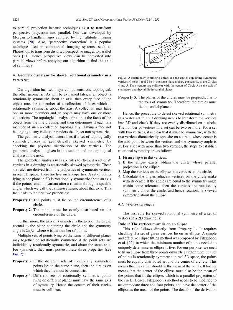
Multiple sets of points lying on the same or different planesmay together be rotationally symmetric if the point sets areindividually rotationally symmetric, and about the same axis.For symmetry, they must possess these three properties (seeFig. 2):
Property 3: If the different sets of rotationally symmetricpoints lie on the same plane, then the circles onwhich they lie must be concentric.
Property 4: Different sets of rotationally symmetric pointslying on different planes must have the same axisof symmetry. Hence the centers of their circlesmust be collinear.
Fig. 2. A rotationally symmetric object and the circles containing symmetricvertices. Circles 1 and 2 lie in the same plane and are concentric, so are Circles4 and 5. Their centers are collinear with the center of Circle 3 on the axis ofsymmetry, and they all lie in parallel planes.
Property 5: The planes of the circles must be perpendicular tothe axis of symmetry. Therefore, the circles mustlie in parallel planes.
Hence, the procedure to detect skewed rotational symmetryin a vertex set in a 2D drawing needs to transform the verticesinto 3D and check if they are evenly distributed on a circle.The number of vertices in a set can be two or more. For a setwith two vertices, it is clear that it must be symmetric, with thetwo vertices diametrically opposite on a circle, whose center isthe mid-point between the vertices and the symmetry angle isπ . For a set with more than two vertices, the steps to establishrotational symmetry are as follow:
1. Fit an ellipse to the vertices.2. If the ellipse exists, obtain the circle whose parallel
projection is the ellipse.3. Map the vertices on the ellipse into vertices on the circle.4. Calculate the angles adjacent vertices on the circle make
with its center. If the angles are equal to the symmetry anglewithin some tolerance, then the vertices are rotationallysymmetric about the circle, and hence rotationally skewedsymmetric about the ellipse.
4.1. Vertices on ellipse
The first rule for skewed rotational symmetry of a set ofvertices in a 2D drawing is:
Rule 1: The vertices must lie on an ellipseThis rule follows directly from Property 1. It requires
checking if a set of given vertices lie on an ellipse. A simpleand effective ellipse fitting method was proposed by Fitzgibbonet al. [22], in which the minimum number of points needed touniquely determine an ellipse is five. For our purpose, we needto fit an ellipse from three points onwards. Further more, if a setof points is rotationally symmetric in real 3D space, the pointsmust be equally distributed around the center of a circle. Thismeans that the center should be the mean of the points. It furthermeans that the center of the ellipse must also be the mean ofthe points that fit the ellipse, which is a parallel projection ofthe circle. Hence, Fitzgibbon’s method needs to be modified toaccommodate three and four points, and have the center of theellipse as the mean of the points. The details of the derivation
H.L. Zou, Y.T. Lee / Computer-Aided Design 38 (2006) 1224–1232 1227
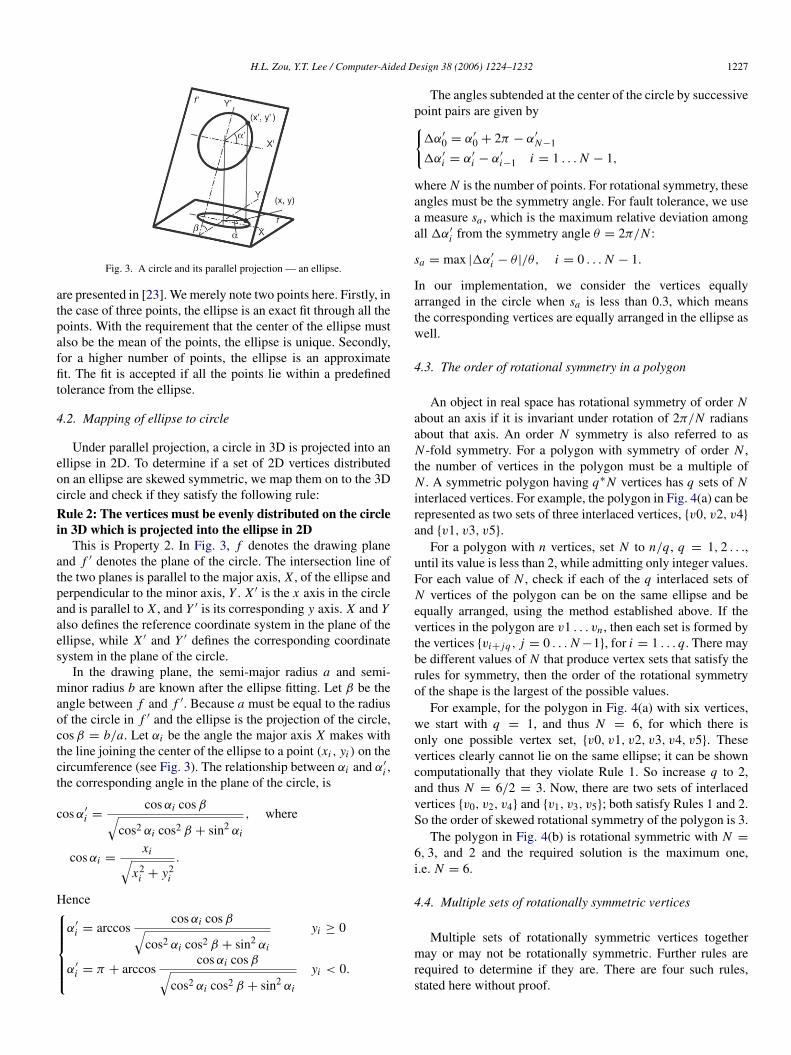
Fig. 3. A circle and its parallel projection — an ellipse.
are presented in [23]. We merely note two points here. Firstly, inthe case of three points, the ellipse is an exact fit through all thepoints. With the requirement that the center of the ellipse mustalso be the mean of the points, the ellipse is unique. Secondly,for a higher number of points, the ellipse is an approximatefit. The fit is accepted if all the points lie within a predefinedtolerance from the ellipse.
4.2. Mapping of ellipse to circle
Under parallel projection, a circle in 3D is projected into anellipse in 2D. To determine if a set of 2D vertices distributedon an ellipse are skewed symmetric, we map them on to the 3Dcircle and check if they satisfy the following rule:
Rule 2: The vertices must be evenly distributed on the circlein 3D which is projected into the ellipse in 2D
This is Property 2. In Fig. 3, f denotes the drawing planeand f ′ denotes the plane of the circle. The intersection line ofthe two planes is parallel to the major axis, X , of the ellipse andperpendicular to the minor axis, Y . X ′ is the x axis in the circleand is parallel to X , and Y ′ is its corresponding y axis. X and Yalso defines the reference coordinate system in the plane of theellipse, while X ′ and Y ′ defines the corresponding coordinatesystem in the plane of the circle.
In the drawing plane, the semi-major radius a and semi-minor radius b are known after the ellipse fitting. Let β be theangle between f and f ′. Because a must be equal to the radiusof the circle in f ′ and the ellipse is the projection of the circle,cos β = b/a. Let αi be the angle the major axis X makes withthe line joining the center of the ellipse to a point (xi , yi ) on thecircumference (see Fig. 3). The relationship between αi and α′
i ,the corresponding angle in the plane of the circle, is
cos α′
i =cos αi cos β√
cos2 αi cos2 β + sin2 αi
, where
cos αi =xi√
x2i + y2
i
.
Henceα′
i = arccoscos αi cos β√
cos2 αi cos2 β + sin2 αi
yi ≥ 0
α′
i = π + arccoscos αi cos β√
cos2 αi cos2 β + sin2 αi
yi < 0.
The angles subtended at the center of the circle by successivepoint pairs are given by{
1α′
0 = α′
0 + 2π − α′
N−1
1α′
i = α′
i − α′
i−1 i = 1 . . . N − 1,
where N is the number of points. For rotational symmetry, theseangles must be the symmetry angle. For fault tolerance, we usea measure sa , which is the maximum relative deviation amongall 1α′
i from the symmetry angle θ = 2π/N :
sa = max |1α′
i − θ |/θ, i = 0 . . . N − 1.
In our implementation, we consider the vertices equallyarranged in the circle when sa is less than 0.3, which meansthe corresponding vertices are equally arranged in the ellipse aswell.
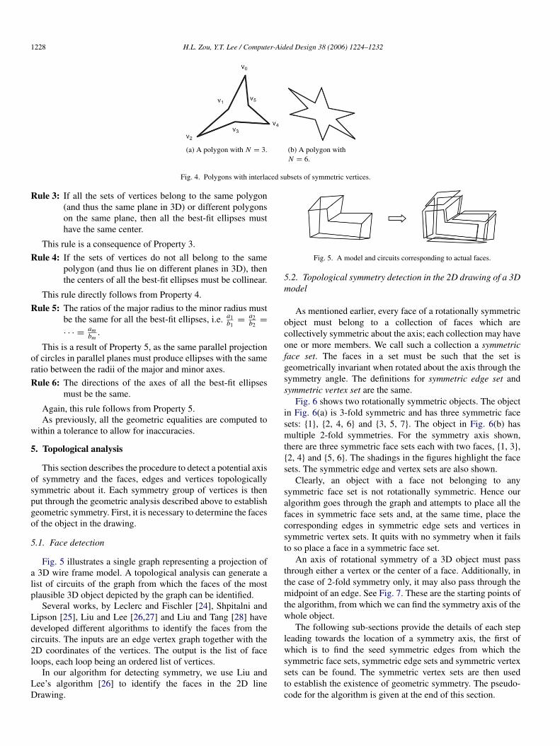
4.3. The order of rotational symmetry in a polygon
An object in real space has rotational symmetry of order Nabout an axis if it is invariant under rotation of 2π/N radiansabout that axis. An order N symmetry is also referred to asN -fold symmetry. For a polygon with symmetry of order N ,the number of vertices in the polygon must be a multiple ofN . A symmetric polygon having q∗N vertices has q sets of Ninterlaced vertices. For example, the polygon in Fig. 4(a) can berepresented as two sets of three interlaced vertices, {v0, v2, v4}
and {v1, v3, v5}.For a polygon with n vertices, set N to n/q, q = 1, 2 . . .,
until its value is less than 2, while admitting only integer values.For each value of N , check if each of the q interlaced sets ofN vertices of the polygon can be on the same ellipse and beequally arranged, using the method established above. If thevertices in the polygon are v1 . . . vn , then each set is formed bythe vertices {vi+ jq , j = 0 . . . N −1}, for i = 1 . . . q. There maybe different values of N that produce vertex sets that satisfy therules for symmetry, then the order of the rotational symmetryof the shape is the largest of the possible values.
For example, for the polygon in Fig. 4(a) with six vertices,we start with q = 1, and thus N = 6, for which there isonly one possible vertex set, {v0, v1, v2, v3, v4, v5}. Thesevertices clearly cannot lie on the same ellipse; it can be showncomputationally that they violate Rule 1. So increase q to 2,and thus N = 6/2 = 3. Now, there are two sets of interlacedvertices {v0, v2, v4} and {v1, v3, v5}; both satisfy Rules 1 and 2.So the order of skewed rotational symmetry of the polygon is 3.
The polygon in Fig. 4(b) is rotational symmetric with N =
6, 3, and 2 and the required solution is the maximum one,i.e. N = 6.
4.4. Multiple sets of rotationally symmetric vertices
Multiple sets of rotationally symmetric vertices togethermay or may not be rotationally symmetric. Further rules arerequired to determine if they are. There are four such rules,stated here without proof.
1228 H.L. Zou, Y.T. Lee / Computer-Aided Design 38 (2006) 1224–1232
(a) A polygon with N = 3. (b) A polygon withN = 6.
Fig. 4. Polygons with interlaced subsets of symmetric vertices.
Rule 3: If all the sets of vertices belong to the same polygon(and thus the same plane in 3D) or different polygonson the same plane, then all the best-fit ellipses musthave the same center.
This rule is a consequence of Property 3.
Rule 4: If the sets of vertices do not all belong to the samepolygon (and thus lie on different planes in 3D), thenthe centers of all the best-fit ellipses must be collinear.
This rule directly follows from Property 4.
Rule 5: The ratios of the major radius to the minor radius mustbe the same for all the best-fit ellipses, i.e. a1
b1=
a2b2
=
· · · =ambm
.
This is a result of Property 5, as the same parallel projectionof circles in parallel planes must produce ellipses with the sameratio between the radii of the major and minor axes.
Rule 6: The directions of the axes of all the best-fit ellipsesmust be the same.
Again, this rule follows from Property 5.As previously, all the geometric equalities are computed to
within a tolerance to allow for inaccuracies.
5. Topological analysis
This section describes the procedure to detect a potential axisof symmetry and the faces, edges and vertices topologicallysymmetric about it. Each symmetry group of vertices is thenput through the geometric analysis described above to establishgeometric symmetry. First, it is necessary to determine the facesof the object in the drawing.
5.1. Face detection
Fig. 5 illustrates a single graph representing a projection ofa 3D wire frame model. A topological analysis can generate alist of circuits of the graph from which the faces of the mostplausible 3D object depicted by the graph can be identified.
Several works, by Leclerc and Fischler [24], Shpitalni andLipson [25], Liu and Lee [26,27] and Liu and Tang [28] havedeveloped different algorithms to identify the faces from thecircuits. The inputs are an edge vertex graph together with the2D coordinates of the vertices. The output is the list of faceloops, each loop being an ordered list of vertices.
In our algorithm for detecting symmetry, we use Liu andLee’s algorithm [26] to identify the faces in the 2D lineDrawing.
Fig. 5. A model and circuits corresponding to actual faces.
5.2. Topological symmetry detection in the 2D drawing of a 3Dmodel
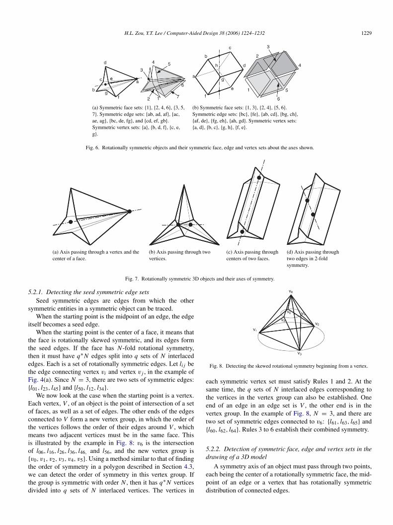
As mentioned earlier, every face of a rotationally symmetricobject must belong to a collection of faces which arecollectively symmetric about the axis; each collection may haveone or more members. We call such a collection a symmetricface set. The faces in a set must be such that the set isgeometrically invariant when rotated about the axis through thesymmetry angle. The definitions for symmetric edge set andsymmetric vertex set are the same.
Fig. 6 shows two rotationally symmetric objects. The objectin Fig. 6(a) is 3-fold symmetric and has three symmetric facesets: {1}, {2, 4, 6} and {3, 5, 7}. The object in Fig. 6(b) hasmultiple 2-fold symmetries. For the symmetry axis shown,there are three symmetric face sets each with two faces, {1, 3},{2, 4} and {5, 6}. The shadings in the figures highlight the facesets. The symmetric edge and vertex sets are also shown.
Clearly, an object with a face not belonging to anysymmetric face set is not rotationally symmetric. Hence ouralgorithm goes through the graph and attempts to place all thefaces in symmetric face sets and, at the same time, place thecorresponding edges in symmetric edge sets and vertices insymmetric vertex sets. It quits with no symmetry when it failsto so place a face in a symmetric face set.
An axis of rotational symmetry of a 3D object must passthrough either a vertex or the center of a face. Additionally, inthe case of 2-fold symmetry only, it may also pass through themidpoint of an edge. See Fig. 7. These are the starting points ofthe algorithm, from which we can find the symmetry axis of thewhole object.
The following sub-sections provide the details of each stepleading towards the location of a symmetry axis, the first ofwhich is to find the seed symmetric edges from which thesymmetric face sets, symmetric edge sets and symmetric vertexsets can be found. The symmetric vertex sets are then usedto establish the existence of geometric symmetry. The pseudo-code for the algorithm is given at the end of this section.
H.L. Zou, Y.T. Lee / Computer-Aided Design 38 (2006) 1224–1232 1229
(a) Symmetric face sets: {1}, {2, 4, 6}, {3, 5,7}. Symmetric edge sets: {ab, ad, af}, {ac,ae, ag}, {bc, de, fg}, and {cd, ef, gb}.Symmetric vertex sets: {a}, {b, d, f}, {c, e,g}.
(b) Symmetric face sets: {1, 3}, {2, 4}, {5, 6}.Symmetric edge sets: {bc}, {fe}, {ab, cd}, {bg, ch},{af, de}, {fg, eh}, {ah, gd}. Symmetric vertex sets:{a, d}, {b, c}, {g, h}, {f, e}.
Fig. 6. Rotationally symmetric objects and their symmetric face, edge and vertex sets about the axes shown.
(a) Axis passing through a vertex and thecenter of a face.
(b) Axis passing through twovertices.
(c) Axis passing throughcenters of two faces.
(d) Axis passing throughtwo edges in 2-foldsymmetry.
Fig. 7. Rotationally symmetric 3D objects and their axes of symmetry.
5.2.1. Detecting the seed symmetric edge setsSeed symmetric edges are edges from which the other
symmetric entities in a symmetric object can be traced.When the starting point is the midpoint of an edge, the edge
itself becomes a seed edge.When the starting point is the center of a face, it means that
the face is rotationally skewed symmetric, and its edges formthe seed edges. If the face has N -fold rotational symmetry,then it must have q∗N edges split into q sets of N interlacededges. Each is a set of rotationally symmetric edges. Let li j bethe edge connecting vertex vi and vertex v j , in the example ofFig. 4(a). Since N = 3, there are two sets of symmetric edges:{l01, l23, l45} and {l50, l12, l34}.
We now look at the case when the starting point is a vertex.Each vertex, V , of an object is the point of intersection of a setof faces, as well as a set of edges. The other ends of the edgesconnected to V form a new vertex group, in which the order ofthe vertices follows the order of their edges around V , whichmeans two adjacent vertices must be in the same face. Thisis illustrated by the example in Fig. 8: v6 is the intersectionof l06, l16, l26, l36, l46, and l56, and the new vertex group is{v0, v1, v2, v3, v4, v5}. Using a method similar to that of findingthe order of symmetry in a polygon described in Section 4.3,we can detect the order of symmetry in this vertex group. Ifthe group is symmetric with order N , then it has q∗N verticesdivided into q sets of N interlaced vertices. The vertices in
Fig. 8. Detecting the skewed rotational symmetry beginning from a vertex.
each symmetric vertex set must satisfy Rules 1 and 2. At thesame time, the q sets of N interlaced edges corresponding tothe vertices in the vertex group can also be established. Oneend of an edge in an edge set is V , the other end is in thevertex group. In the example of Fig. 8, N = 3, and there aretwo set of symmetric edges connected to v6: {l61, l63, l65} and{l60, l62, l64}. Rules 3 to 6 establish their combined symmetry.
5.2.2. Detection of symmetric face, edge and vertex sets in thedrawing of a 3D model
A symmetry axis of an object must pass through two points,each being the center of a rotationally symmetric face, the mid-point of an edge or a vertex that has rotationally symmetricdistribution of connected edges.
1230 H.L. Zou, Y.T. Lee / Computer-Aided Design 38 (2006) 1224–1232
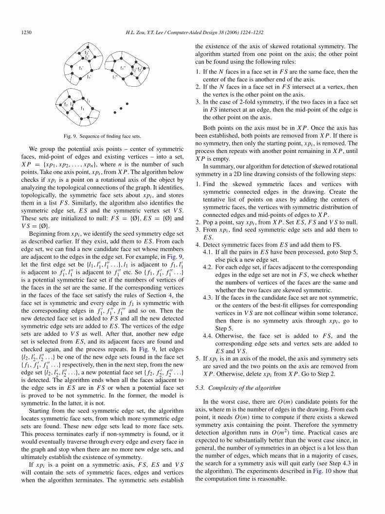
Fig. 9. Sequence of finding face sets.
We group the potential axis points – center of symmetricfaces, mid-point of edges and existing vertices – into a set,X P = {xp1, xp2, . . . , xpn}, where n is the number of suchpoints. Take one axis point, xpi , from X P . The algorithm belowchecks if xpi is a point on a rotational axis of the object byanalyzing the topological connections of the graph. It identifies,topologically, the symmetric face sets about xpi , and storesthem in a list F S. Similarly, the algorithm also identifies thesymmetric edge set, E S and the symmetric vertex set V S.These sets are initialized to null: F S = {Ø}, E S = {Ø} andV S = {Ø}.
Beginning from xpi , we identify the seed symmetry edge setas described earlier. If they exist, add them to E S. From eachedge set, we can find a new candidate face set whose membersare adjacent to the edges in the edge set. For example, in Fig. 9,let the first edge set be {l1, l ′1, l ′′1 . . .}, l1 is adjacent to f1, l ′1is adjacent to f ′
1, l ′′1 is adjacent to f ′′
1 etc. So { f1, f ′
1, f ′′
1 . . .}
is a potential symmetric face set if the numbers of vertices ofthe faces in the set are the same. If the corresponding verticesin the faces of the face set satisfy the rules of Section 4, theface set is symmetric and every edge in f1 is symmetric withthe corresponding edges in f ′
1, f ′′
1 , f ′′′
1 and so on. Then thenew detected face set is added to F S and all the new detectedsymmetric edge sets are added to E S. The vertices of the edgesets are added to V S as well. After that, another new edgeset is selected from E S, and its adjacent faces are found andchecked again, and the process repeats. In Fig. 9, let edges{l2, l ′2, l ′′2 . . .} be one of the new edge sets found in the face set{ f1, f ′
1, f ′′
1 . . .} respectively, then in the next step, from the newedge set {l2, l ′2, l ′′2 . . .}, a new potential face set { f2, f ′
2, f ′′
2 . . .}
is detected. The algorithm ends when all the faces adjacent tothe edge sets in E S are in F S or when a potential face setis proved to be not symmetric. In the former, the model issymmetric. In the latter, it is not.
Starting from the seed symmetric edge set, the algorithmlocates symmetric face sets, from which more symmetric edgesets are found. These new edge sets lead to more face sets.This process terminates early if non-symmetry is found, or itwould eventually traverse through every edge and every face inthe graph and stop when there are no more new edge sets, andultimately establish the existence of symmetry.
If xpi is a point on a symmetric axis, F S, E S and V Swill contain the sets of symmetric faces, edges and verticeswhen the algorithm terminates. The symmetric sets establish
the existence of the axis of skewed rotational symmetry. Thealgorithm started from one point on the axis; the other pointcan be found using the following rules:
1. If the N faces in a face set in F S are the same face, then thecenter of the face is another end of the axis.
2. If the N faces in a face set in F S intersect at a vertex, thenthe vertex is the other point on the axis.
3. In the case of 2-fold symmetry, if the two faces in a face setin FS intersect at an edge, then the mid-point of the edge isthe other point on the axis.
Both points on the axis must be in X P . Once the axis hasbeen established, both points are removed from X P . If there isno symmetry, then only the starting point, xpi , is removed. Theprocess then repeats with another point remaining in X P , untilX P is empty.
In summary, our algorithm for detection of skewed rotationalsymmetry in a 2D line drawing consists of the following steps:
1. Find the skewed symmetric faces and vertices withsymmetric connected edges in the drawing. Create thetentative list of points on axes by adding the centers ofsymmetric faces, the vertices with symmetric distribution ofconnected edges and mid-points of edges to X P .
2. Pop a point, say xpi , from X P . Set E S, F S and V S to null.3. From xpi , find seed symmetric edge sets and add them to
E S.4. Detect symmetric faces from E S and add them to FS.
4.1. If all the pairs in E S have been processed, goto Step 5,else pick a new edge set.
4.2. For each edge set, if faces adjacent to the correspondingedges in the edge set are not in F S, we check whetherthe numbers of vertices of the faces are the same andwhether the two faces are skewed symmetric.
4.3. If the faces in the candidate face set are not symmetric,or the centers of the best-fit ellipses for correspondingvertices in V S are not collinear within some tolerance,then there is no symmetry axis through xpi , go toStep 5.
4.4. Otherwise, the face set is added to F S, and thecorresponding edge sets and vertex sets are added toE S and V S.
5. If xpi is in an axis of the model, the axis and symmetry setsare saved and the two points on the axis are removed fromX P . Otherwise, delete xpi from X P . Go to Step 2.
5.3. Complexity of the algorithm
In the worst case, there are O(m) candidate points for theaxis, where m is the number of edges in the drawing. From eachpoint, it needs O(m) time to compute if there exists a skewedsymmetry axis containing the point. Therefore the symmetrydetection algorithm runs in O(m2) time. Practical cases areexpected to be substantially better than the worst case since, ingeneral, the number of symmetries in an object is a lot less thanthe number of edges, which means that in a majority of cases,the search for a symmetry axis will quit early (see Step 4.3 inthe algorithm). The experiments described in Fig. 10 show thatthe computation time is reasonable.
H.L. Zou, Y.T. Lee / Computer-Aided Design 38 (2006) 1224–1232 1231
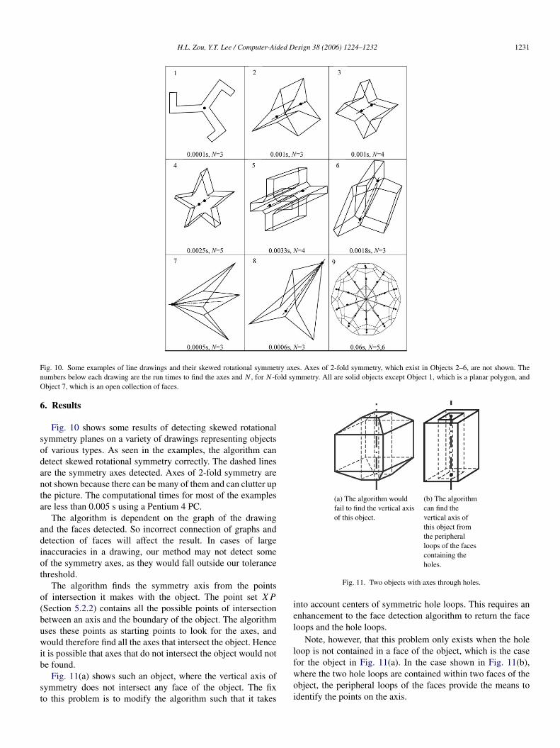
Fig. 10. Some examples of line drawings and their skewed rotational symmetry axes. Axes of 2-fold symmetry, which exist in Objects 2–6, are not shown. Thenumbers below each drawing are the run times to find the axes and N , for N -fold symmetry. All are solid objects except Object 1, which is a planar polygon, andObject 7, which is an open collection of faces.
6. Results
Fig. 10 shows some results of detecting skewed rotationalsymmetry planes on a variety of drawings representing objectsof various types. As seen in the examples, the algorithm candetect skewed rotational symmetry correctly. The dashed linesare the symmetry axes detected. Axes of 2-fold symmetry arenot shown because there can be many of them and can clutter upthe picture. The computational times for most of the examplesare less than 0.005 s using a Pentium 4 PC.
The algorithm is dependent on the graph of the drawingand the faces detected. So incorrect connection of graphs anddetection of faces will affect the result. In cases of largeinaccuracies in a drawing, our method may not detect someof the symmetry axes, as they would fall outside our tolerancethreshold.
The algorithm finds the symmetry axis from the pointsof intersection it makes with the object. The point set X P(Section 5.2.2) contains all the possible points of intersectionbetween an axis and the boundary of the object. The algorithmuses these points as starting points to look for the axes, andwould therefore find all the axes that intersect the object. Henceit is possible that axes that do not intersect the object would notbe found.
Fig. 11(a) shows such an object, where the vertical axis ofsymmetry does not intersect any face of the object. The fixto this problem is to modify the algorithm such that it takes
(a) The algorithm wouldfail to find the vertical axisof this object.
(b) The algorithmcan find thevertical axis ofthis object fromthe peripheralloops of the facescontaining theholes.
Fig. 11. Two objects with axes through holes.
into account centers of symmetric hole loops. This requires anenhancement to the face detection algorithm to return the faceloops and the hole loops.
Note, however, that this problem only exists when the holeloop is not contained in a face of the object, which is the casefor the object in Fig. 11(a). In the case shown in Fig. 11(b),where the two hole loops are contained within two faces of theobject, the peripheral loops of the faces provide the means toidentify the points on the axis.
1232 H.L. Zou, Y.T. Lee / Computer-Aided Design 38 (2006) 1224–1232
7. Conclusion
A new algorithm for the detection of the skewed rotationalsymmetry axes of a line drawing of a 3D polyhedral modelhas been presented. It works by identifying topologicallysymmetric sets of vertices and checks that they aregeometrically symmetric by ensuring that they satisfy the rulesgiven in Section 4. We have implemented the algorithm and thetests show that it works well, with adjustable fault tolerance.
The algorithm can be improved by easing some of therestrictions stated in Section 3, such as in the handling ofdrawings with hidden lines removed. Missing edges meanthat some information required by our algorithm to derivethe symmetry axes is not available, and needs to be filled inautomatically. Such filling in can only be speculative, but thiscan be aided by checking the symmetry of the visible entities. Aface containing a point through which a symmetry axis passesmust be rotationally symmetric itself. Likewise, if this point isa vertex or the mid-point of an edge, then the faces borderingthis vertex or edge must be collectively rotationally symmetric.It is possible to use such a point as the starting point to attemptto construct the missing symmetric faces. The work in this areais now being pursued.
Drawings with curves are beyond the scope of this study, butwork is already in progress in tackling this important problem.
References
[1] Lipson H, Shpitalni M. Optimization-based reconstruction of a 3D objectfrom a single freehand line drawing. Computer Aided Design 1996;28(8):651–63.
[2] Langbein FC, Marshall AD, Martin RR. Choosing consistent constraintsfor beautification of reverse engineered geometric models. ComputerAided Design 2004;36(3):261–78.
[3] Cham TJ, Cipolla R. Symmetry detection through local skewedsymmetries. Image and Vision Computing 1995;13:439–50.
[4] Leou J, Tsai W. Automatic rotational symmetry determination for shapeanalysis. Pattern Recognition 1987;20:571–82.
[5] Marola G. On the detection of the axes of symmetry of symmetric andalmost symmetric planar images. IEEE Transaction on Pattern Analysisand Machine Intelligence 1989;11:104–8.
[6] Piquer A, Company P, Martin RR. Skewed mirror symmetry in the 3Dreconstruction of polyhedral models. Journal of WSCG 2003;11.
[7] Lei Y, Wong KC. A novel method for detecting and localising ofreflectional and rotational symmetry under weak perspective projection.International Conference on Pattern Recognition 1998;1:417–9.
[8] Zou HL, Lee YT. Skewed symmetry detection from a 2D sketch of a 3Dmodel. In: International conference on computer graphics and interactivetechniques in Australasia and Southeast Asia. 2005.
[9] Kanade T. Recovery of the three-dimensional shape of an object from asingle view. Artificial Intelligence 1981;17:409–60.
[10] Matsuda T, Yamamoto K, Yamada H. Detection of partial symmetry usingcorrelation with rotated-reflected images. Pattern Recognition 1993;26(8):1245–53.
[11] Shen DG, Ip HHS, Teoh EK. Robust detection of skewed symmetriesby combining local and semi-local affine invariants. Pattern Recognition2001;34:1417–28.
[12] Yip RKK, Tam PKS, Leung DNK. Application of elliptic Fourierdescriptors to symmetry detection under parallel projection. IEEETransactions on Pattern Analysis and Machine Intelligence 1994;16(3):277–86.
[13] Yip RKK. A HOUGH transform technique for the detection of parallelprojected rotational symmetry. Pattern Recognition Letters 1999;20(10):991–1004.
[14] Glachet R, Dhome M, Laprest’e J-T. Finding the perspective projection ofan axis of revolution. Pattern Recognition Letters 1991;12(11):693–700.
[15] Xu G, Tanaka HT, Tsuji S. Right straight homogeneous generalizedcylinders with symmetric cross-sections: Recovery of pose and shapefrom image contours. IEEE Conference on Computer Vision and PatternRecognition 1992;692–4.
[16] Zabrodsky H, Peleg S, Avnir D. Hierarchical symmetry. In: Proc. int’lconf pattern recognition. 1992. p. 9–11.
[17] Zabrodsky H. Computational aspects of pattern characterization —continuous symmetry. Jerusalem (Israel): Hebrew University; 1993.
[18] Zabrodsky H, Weinshall D. 3D symmetry from 2D data. In: Proc.European conf. computer vision. 1994.
[19] Zabrodsky H, Peleg S, Avnir D. Symmetry as a continuous feature. IEEETransactions on Pattern Analysis and Machine Intelligence 1995;17(12):1154–66.
[20] Morgan M. Epipolar resampling of linear array scanner scenes. Ph.D. the-sis. University of Calgary; 2004. Also available at http://www.geomatics.ucalgary.ca/Papers/Thesis/AH/04.20193.MMorgan.pdf [chapter 5].
[21] Adobe Photoshop 7.0 On-line Manual. Chapter on transformingperspective.
[22] Fitzgibbon AW, Pilu M, Fisher RB. Direct least-squares fitting of ellipses.IEEE Transactions on Pattern Analysis and Machine Intelligence 1999;21:476–80.
[23] Zou HL. Constraint-based beautification of 3D objects constructed from2D line drawings. Ph.D. thesis. Nanyang Technological University; 2006.
[24] Leclerc YG, Fiscler MA. An optimization based approach to theinterpretation of single line drawings as 3D wire frame. Computer Vision1992;9:113–36.
[25] Shpitalni M, Lipson H. Identification of faces in a 2D line drawingprojection of a wire frame object. IEEE Transactions on Pattern Analysisand Machine Intelligence 1996;18(10):1000–12.
[26] Liu J, Lee YT. A graph-based method for face identification from a single2D line drawing. IEEE Transaction on Pattern Analysis and MachineIntelligence 2001;23(10):1089–106.
[27] Liu J, Lee YT, Cham WK. Identifying faces in a 2D line drawingrepresenting a manifold object. IEEE Transaction on Pattern Analysis andMachine Intelligence 2002;24(12):1579–93.
[28] Liu J, Tang X. Evolutionary search for faces from line drawings. IEEETransactions on Pattern Analysis and Machine Intelligence 2005;27(6).


