
SL150 Standing Seam(formerly CSL)
Installation Manual
PO Box 229Fayetteville, NC 28302
Toll-Free(888) MTL-ROOF
www.unionmetalroofing.com. .Rev. 2/09

IMPORTANT NOTICE
This manual contains suggestions and guidelines on how to install the subject
Union Corrugating panels and trim details. The contents of this manual include
the guidelines that were in effect at the time this publication was originally
printed. In an effort to keep pace with the ever-changing code environment,
Union Corrugating retains the right to change specifications and / or designs at
any time without incurring any obligations. To insure you have the latest infor-
mation available, please inquire or visit our web site. Application and design
details are for illustrative purposes only and may not be appropriate for all envi-
ronmental conditions and/or building designs. Projects should be engineered
and installed to conform to applicable building codes, regulations, and accepted
industry practices.
TABLE OF CONTENTS
Introduction, Tools, Safety, & Packaging …………………………………………
Storage & Handling ………………………………………………………………
Field Cutting ………………………………………………………………………
Design & Installation Considerations ……………………………………………
SL150 Accessories & Trim Profiles ………………………………………………
Panel Installation …………………………………………………………………
Trim Installation & Details ……………………………………………………… Vented Ridge …………………………………………………………
Flat Hip & Ridge ………………………………………………………
Single Sloped Ridge …………………………………………………
Plumb Eave …………………………………………………………
Hemmed Floating Rake ………………………………………………
Floating Rake …………………………………………………………
Fixed Rake ……………………………………………………………
Valley ………………………………………………………………
Side Wall ……………………………………………………………
End Wall ……………………………………………………………
Transition ……………………………………………………………
Mansard Transition …………………………………………………
3-4
5-7
8
8-9
10-11
12
13-24
13
14
15
16
17
18
19
20
21
22
23
24

WITH MINOR STRIATIONS
Available Specifications:
Applications:
INTRODUCTION DESIGN
TESTING
The CSL (Clipped Snap Lock) Standing Seam panel is a popular 1.5” rib style that installs with concealed clips. Because of their installation methods, CSL Panels can “float” on the roof deck allowing for maximum expansion and contraction. The CSL Standing Seam panel is designed to be installed over a solid deck on roof pitches of 3 on 12 and greater. With proper handling and installation, your CSL panels will provide years of leak-free performance and beauty. Please review this manual carefully and completely before beginning your installation.
CSL is an architectural (non-structural) panel that is ideal for commercial and residential applications. It can be used for roofing, mansards, or fascias. The panels must be applied over a solid substrate. Green, wet and treated wood should not be used in direct contact with any CSL panels.
Colors and Finishes:The CSL panel is available in 26 or 24 ga steel. 26 ga panels use our 40 yr SMP paint system and 24 ga panels use a PVDF (Kynar®) system. Warranty copies are available upon request.
Widths:The CSL panel is available in 16” coverage width. The 1/16” striations provide strength and reduce the incidence of oil canning in the panel.
Lengths:The CSL Panel is available in standard lengths from 3’ to 40’. Longer lengths require additional handling, packaging, and shipping considerations. An extra handling charge may apply to panels over 40’. Please consult your local Union Corrugating office for recommendations. CSL panels can be end lapped.
Rib Height:The full 1.5” high rib provides for improved leak resistanceover other typical panels. Some prefer this higher rib for thefinished look it presents.
Coverage 16”
1 ½”
This manual contains suggestions and guidelines on how to install CSL panels. The installation details shown are proven methods of construction, but are not intended tocover all instances, building requirements, designs, or codes.It is the responsibility of the designer/installer to ensure thatthe details meet particular building requirements. The designer/installer must be aware of , and allow for, expansion/contraction of roof panels. The details may require changes or revisions due to each project’s conditions.
There are certain minimum wind loads and snow loads that aroof must generally be designed to support. Consult localbuilding officials to determine the appropriate buildingdesign load requirements. A professional engineer should beconsulted for all roof system designs. It is the buyer’sresponsibility to verify all applicable code requirements,check all measurements, and determine suitability of productfor job. Any job estimates or take-offs provided by UnionCorrugating are for reference only. The buyer is responsiblefor verifying actual length and quantities needed. Impliedwarranties of merchantability and fitness for a particularpurpose are disclaimed. All CSL instructions assume that a qualified firm or individual has been contacted regarding applications of this product. Failure to comply with stated recommendations relieves the manufacturer of responsibility for any damage or deterioration of the product incurred and voids any applicable warranty.
Florida Building Code High Velocity Hurricane Zone Approval #FL 9443.1
UL 580 - Construction No: 589UL Class 4 ImpactASTM 331ASTM E-330ASTM 1592ASTM 283
3
!
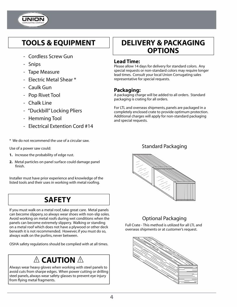
TOOLS & EQUIPMENT DELIVERY & PACKAGINGOPTIONS
SAFETY
- Cordless Screw Gun
- Snips
- Tape Measure
- Electric Metal Shear *
- Caulk Gun
- Pop Rivet Tool
- Chalk Line
- “Duckbill” Locking Pliers
- Hemming Tool
- Electrical Extention Cord #14
* We do not recommend the use of a circular saw.
Use of a power saw could:
1. Increase the probability of edge rust.
2. Metal particles on panel surface could damage panel finish.
Installer must have prior experience and knowledge of the listed tools and their uses in working with metal roofing.
If you must walk on a metal roof, take great care. Metal panelscan become slippery, so always wear shoes with non-slip soles.Avoid working on metal roofs during wet conditions when the panels can become extremely slippery. Walking or standingon a metal roof which does not have a plywood or other deckbeneath it is not recommended. However, if you must do so,always walk on the purlins, never between.
OSHA safety regulations should be complied with at all times.
Always wear heavy gloves when working with steel panels toavoid cuts from sharpe edges. When power cutting or drillingsteel panels, always wear safety glasses to prevent eye injuryfrom flying metal fragments.
CAUTION !
Lead Time:Please allow 14 days for delivery for standard colors. Anyspecial requests or non-standard colors may require longerlead times. Consult your local Union Corrugating sales representative for special requests.
Packaging:A packaging charge will be added to all orders. Standard packaging is crating for all orders.
For LTL and overseas shipments, panels are packaged in a completely enclosed crate to provide optimum protection.Additional charges will apply for non-standard packagingand special requests.
Standard Packaging
Optional PackagingFull Crate - This method is utilized for all LTL and overseas shipments or at customer’s request.
4
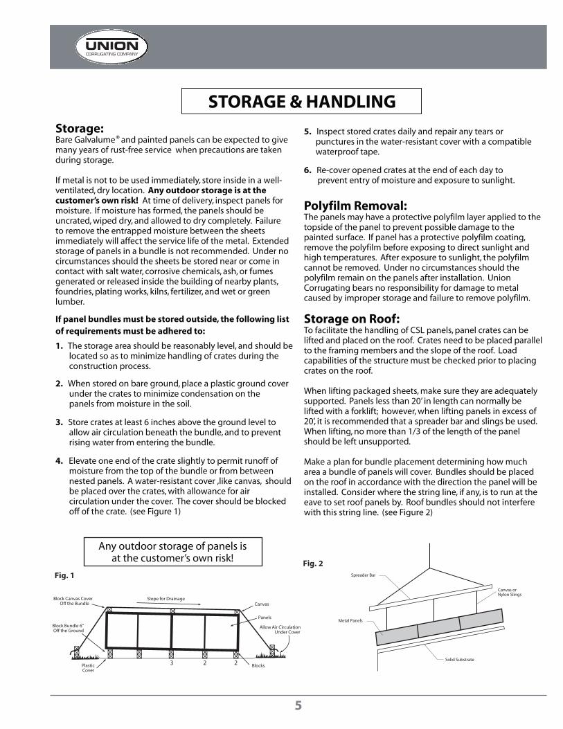
Spreader Bar
Metal Panels
Solid Substrate
Canvas orNylon Slings
3 2
Slope for DrainageBlock Canvas CoverOff the Bundle
PlasticCover
Block Bundle 6"Off the Ground
Panels
Allow Air CirculationUnder Cover
Blocks2
Canvas
Fig. 1
Fig. 2
STORAGE & HANDLING
Any outdoor storage of panels isat the customer’s own risk!
Storage:Bare Galvalume and painted panels can be expected to give many years of rust-free service when precautions are takenduring storage.
If metal is not to be used immediately, store inside in a well-ventilated, dry location. Any outdoor storage is at the customer’s own risk! At time of delivery, inspect panels formoisture. If moisture has formed, the panels should beuncrated, wiped dry, and allowed to dry completely. Failureto remove the entrapped moisture between the sheets immediately will affect the service life of the metal. Extendedstorage of panels in a bundle is not recommended. Under nocircumstances should the sheets be stored near or come incontact with salt water, corrosive chemicals, ash, or fumesgenerated or released inside the building of nearby plants,foundries, plating works, kilns, fertilizer, and wet or greenlumber.
If panel bundles must be stored outside, the following listof requirements must be adhered to:
1. The storage area should be reasonably level, and should be located so as to minimize handling of crates during the construction process.
2. When stored on bare ground, place a plastic ground cover under the crates to minimize condensation on the panels from moisture in the soil.
3. Store crates at least 6 inches above the ground level to allow air circulation beneath the bundle, and to prevent rising water from entering the bundle.
4. Elevate one end of the crate slightly to permit runoff of moisture from the top of the bundle or from between nested panels. A water-resistant cover ,like canvas, should be placed over the crates, with allowance for air circulation under the cover. The cover should be blocked off of the crate. (see Figure 1)
5. Inspect stored crates daily and repair any tears or punctures in the water-resistant cover with a compatible waterproof tape.
6. Re-cover opened crates at the end of each day to prevent entry of moisture and exposure to sunlight.
Polyfilm Removal:The panels may have a protective polyfilm layer applied to thetopside of the panel to prevent possible damage to thepainted surface. If panel has a protective polyfilm coating,remove the polyfilm before exposing to direct sunlight and high temperatures. After exposure to sunlight, the polyfilmcannot be removed. Under no circumstances should the polyfilm remain on the panels after installation. UnionCorrugating bears no responsibility for damage to metalcaused by improper storage and failure to remove polyfilm.
Storage on Roof:To facilitate the handling of CSL panels, panel crates can be lifted and placed on the roof. Crates need to be placed parallelto the framing members and the slope of the roof. Loadcapabilities of the structure must be checked prior to placingcrates on the roof.
When lifting packaged sheets, make sure they are adequatelysupported. Panels less than 20’ in length can normally be lifted with a forklift; however, when lifting panels in excess of20’, it is recommended that a spreader bar and slings be used. When lifting, no more than 1/3 of the length of the panelshould be left unsupported.
Make a plan for bundle placement determining how mucharea a bundle of panels will cover. Bundles should be placedon the roof in accordance with the direction the panel will be installed. Consider where the string line, if any, is to run at theeave to set roof panels by. Roof bundles should not interferewith this string line. (see Figure 2)
®
5

STORAGE & HANDLING
General Handling:Each crate should be handled carefully to avoid beingdamaged. Care should be taken to prevent bending of thepanel or abrasion to finish. Please follow these steps forproper care while unloading and handling crates in order to prevent panel damage:
1. Crates should remain intact during any handling, and until the individual panels in each bundle are ready to be installed. Crates should never be lifted by the banding.
2. Lift each crate as close as possible to its center of gravity.
3. If the crates are to be lifted with a crane, use a spreader bar of appropriate length, and nylon band slings. (Do not use wire rope slings as they will damge the panels)
4. Depending on panel length, some crates may be lifted by a forklift. When using a forklift, the forks should be spread apart to their maximum spacing, and the load must be centered on the forks to prevent scratching the next panel. A panel should never be picked up by its ends. Instead, lift the panel along its longitudinal edge and carry in a vertical (not flat) position. For panels over 10 feet long, two or more people should lift the panel along the same edge.
5. After crates are opened, individual panels must also be handled carefully to prevent panel buckling or damage to the panel coating. When removing a panel from a crate, it should never be allowed to slide over another panel. The individual panels should be “rolled” out of the crate in order to minimize the chance of panel damage.
6. Soft gloves must be worn when handling panels.
Receiving Materials:It is the responsibility of the installer to unload material fromthe delivery truck. The installer shall be responsible forproviding suitable equipment for unloading of material from the delivery truck.
After receiving material, check the condition of the material,and review the shipment against the shipping list to ensureall materials are accounted for. If damages or shortages arediscovered, it should be noted on the shipping copy at timeof delivery. If material is delivered by common carrier, a claimmust be made with the carrier as soon as possible. If replacement material is required, you must contact UnionCorrugating to place the order. If material is delivered oncompany trucks, note the damages and shortages on the shipping copy. Any damages and shortages must be reportedto Union Corrugating within 48 hours from the time ofshipment.
!
Improper loading and unloading of crates may result inbodily harm and/or material damage. Union Corrugatingis not responsible for bodily injuries and/or materialdamages resulting from improper loading and unloading.
CAUTION !
Manual Handling:
6’ - 8’ Max
Incorrect
6
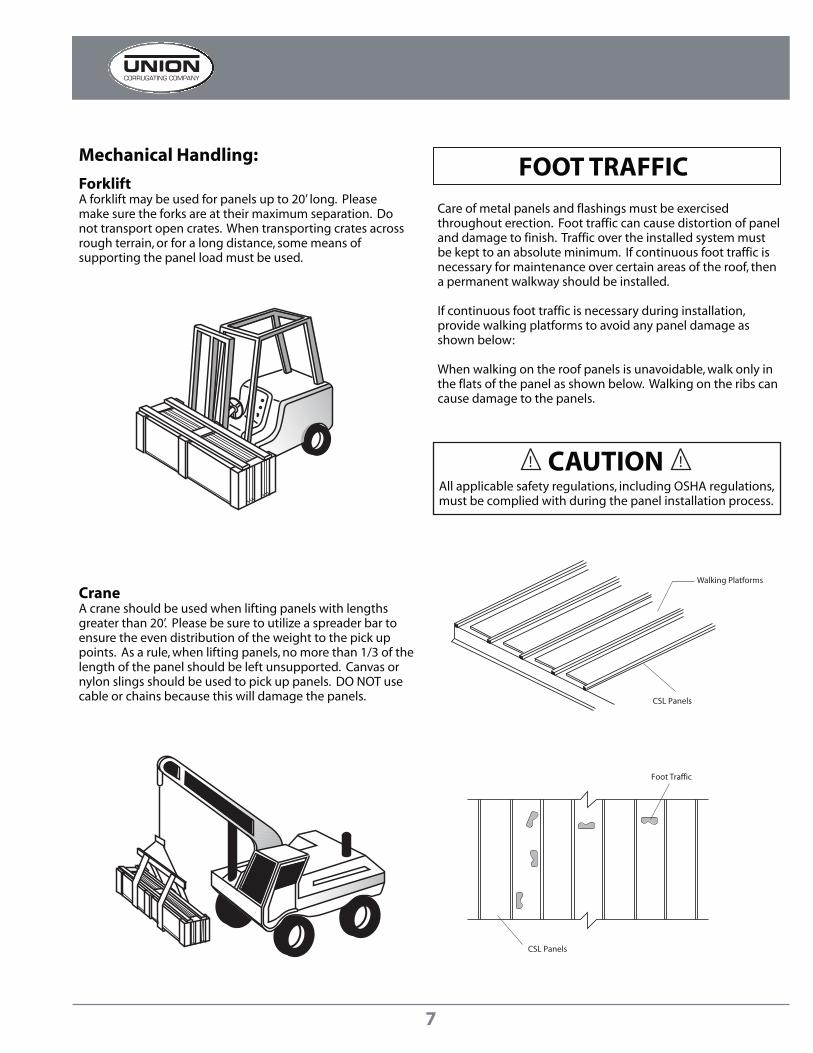
Walking Platforms
CSL Panels
Foot Traffic
CSL Panels
!
All applicable safety regulations, including OSHA regulations,must be complied with during the panel installation process.
CAUTION !
FOOT TRAFFICMechanical Handling:
ForkliftA forklift may be used for panels up to 20’ long. Pleasemake sure the forks are at their maximum separation. Donot transport open crates. When transporting crates acrossrough terrain, or for a long distance, some means ofsupporting the panel load must be used.
CraneA crane should be used when lifting panels with lengthsgreater than 20’. Please be sure to utilize a spreader bar toensure the even distribution of the weight to the pick uppoints. As a rule, when lifting panels, no more than 1/3 of thelength of the panel should be left unsupported. Canvas or nylon slings should be used to pick up panels. DO NOT usecable or chains because this will damage the panels.
Care of metal panels and flashings must be exercisedthroughout erection. Foot traffic can cause distortion of paneland damage to finish. Traffic over the installed system mustbe kept to an absolute minimum. If continuous foot traffic isnecessary for maintenance over certain areas of the roof, thena permanent walkway should be installed.
If continuous foot traffic is necessary during installation, provide walking platforms to avoid any panel damage asshown below:
When walking on the roof panels is unavoidable, walk only inthe flats of the panel as shown below. Walking on the ribs cancause damage to the panels.
7

Vent at Eave
Attic Insulation
VentSmall Brush
Touch-UpPaint
!
When cutting metal panels, goggles must be worn for eyeprotection.
CAUTION !
FIELD CUTTING
All product surfaces should be free of debris at all times.Installed surfaces should be wiped clean at the end of eachwork period. Never cut panels over metal surfaces. Metalshavings will rust on the surface thus voiding the warranty.
! CAUTION !
TOUCH-UP PAINTAll painted panels and flashings have a factory applied bakedon finish. Handling and installing panels may result in somesmall scratches or nicks to the paint finish. Touch-up paint isavailable in matching colors. It is recommended that a smallbrush be used to apply touch-up paint to those areas that arein need of repair. Touch-up paint does not have the superiorchalk and fade resistance of the factory applied paint finishand will normally discolor at an accelerated rate. Aerosolpaint should not be used because of the overspray that mayoccur. Periodic touch-up may be required to maintain color match. There is no warranty on touch-up paint in regards to colormatch because the paint processes are different.
DESIGN CONSIDERATIONS& CALCULATIONS
Insulation & Ventilation:Proper design and installation of vapor barriers and ventilationsystems are important to prevent condensation and theresulting problems of moisture damage and loss of insulationefficiency.
1. The insulation should have a vapor retarder face on the “warm” side of the insulation. For most buildings, this means that the vapor retarder is on the inside surface (toward the building’s interior)
2. The thickness of the insulation must be designed to maintain the temperature of the vapor retarder above the interior dew point, using the worst-case expected outside temperature.
3. All perimeter conditions, seams, and penetrations of the vapor retarder must be adequately sealed in order to provide a continuous membrane to resist the passage of water vapor.
4. Building ventilation, whether by gravity ridge vent, power operated fans, or other means, contributes significantly to reduce condensation. The movement of air to the outside of the building reduces the interior level of vapor pressure.
On buildings that have an attic space or are being retrofittedwith a metal roofing system, vents should be placed at bothends of the eave and peak of the roof in order to prevent a buildup of moisture (humidity) in the attic space
In addition to providing resistance to heat transfer, insulationcan also protect against condensation forming on coldsurfaces, either inside the building or within the wall/roofsystem cavity. The arrangement of the building’s insulationsystem and vapor retarder is the responsibility of the buildingdesigner. These are some basic guidelines to help controlcondensation in a metal building:
Condensation occurs when moisture-laden air comes incontact with a surface temperature equal to or below the dewpoint of the air. This phenomenon creates problems that arenot unique with metal buildings; these problems are common to all types of construction.
Contact your local building code officials or an engineer onproper ventilation practices for your area.
Tin snips or a “nibbler” type electric tool are recommended for field cutting SL150 panels. If a skill saw is used, the blade will generate slivers of metal chips. Any slivers of metal chips must be immediately removed from the SL150 panels because they will damage the finish and shorten the life of the product.
One method of preventing this problem is to flip the panelsover when cutting. This allows the slivers of metal chips to be brushed from the back side and avoids damaging the paint on the top side of the panels.
8
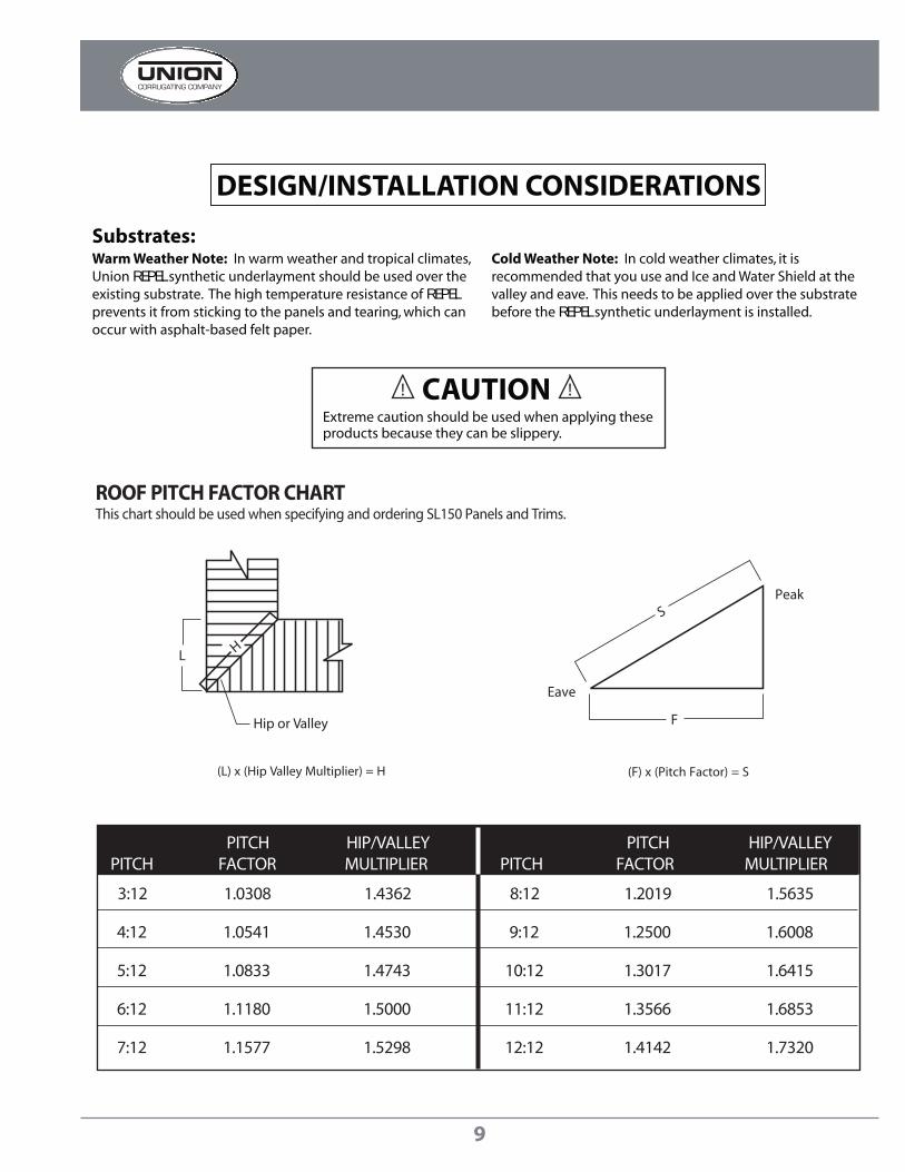
Hip or Valley
L H
(L) x (Hip Valley Multiplier) = H
Eave
F
SPeak
(F) x (Pitch Factor) = S
PITCH HIP/VALLEY PITCH HIP/VALLEYPITCH FACTOR MULTIPLIER PITCH FACTOR MULTIPLIER
3:12 1.0308 1.4362 8:12 1.2019 1.5635
4:12 1.0541 1.4530 9:12 1.2500 1.6008
5:12 1.0833 1.4743 10:12 1.3017 1.6415
6:12 1.1180 1.5000 11:12 1.3566 1.6853
7:12 1.1577 1.5298 12:12 1.4142 1.7320
ROOF PITCH FACTOR CHARTThis chart should be used when specifying and ordering SL150 Panels and Trims.
!
Extreme caution should be used when applying theseproducts because they can be slippery.
CAUTION !
DESIGN/INSTALLATION CONSIDERATIONS
Substrates:Warm Weather Note: In warm weather and tropical climates,Union REPEL synthetic underlayment should be used over theexisting substrate. The high temperature resistance of REPELprevents it from sticking to the panels and tearing, which canoccur with asphalt-based felt paper.
Cold Weather Note: In cold weather climates, it isrecommended that you use and Ice and Water Shield at thevalley and eave. This needs to be applied over the substratebefore the REPEL synthetic underlayment is installed.
9

TUBESEALANT
Urethane Tube Sealant(10.3 oz.)
cccPAINTTUP.6OZ
Touch Up Paint with Brush(.6 oz.)
cccSSPR.125
Pop Rivet (stainless)1/8” x 3/16”
MF3
Pipe BootVarious Sizes, HeatTreated & Retro Fit
Also Available
GPHWS100250
#10 x 1” Pancake HeadWoodscrew
GLTEK
# 14 x 7/8”Hex Head
Lap Tek ScrewMetal-to-Metal
Connection
1-1/2 "
1/2 "
1"
C
160 °160 °
cccALOSCLEAT
Offset Cleat ( 1 ) ( 2 )
1" C
3/4"
3/4"
3/4"
90°
135 °
135 °
5/8"Closed Hem
5/8"Closed Hem
cccALCF
Counter Flashing (1)
C
135 °
3/4"
2-1/4"
cccALCLEAT
Cleat (1)
Flat Sheet
cccPV2029
cccGPV2026
Roll Valley20” x 50’
cccWS150
# 9 x 1-1/2”Hex Head
Woodmate ScrewMetal-to-Wood
Connection
(1) Available in 10’ lengths(2) 26 ga only C Colored side.
Double Bead Butyl Tape(7/8” x 3/16” x 40’)
DBBTLSLT
CSL ACCESSORIES
1"
1"
1-½"
C
cccCSLZCCSLZ-Closure (1)
1-½"36"
1-½"
RCALUNIVERSAL
NeopreneUniversal Closure
HEMMINGTOOL19
Hemming Tool1/8” Opening
1-1/2”
19”
Single Bead Butyl Tape
2” Pancake HeadWoodgrip
GPHDS100250
1” Pancake HeadTek Screw
GPHWS250250GPHWS2502502-1/2” Pancake Head
Tek Screw
BTLSLST
GPHWS200250
G1.5CLIPCSL Panel Clip
CSLVCANCHORCLIP
Vented RidgeAnchor Clip
26ga 41-9/16” x 10’ - cccPFS26415120 or GAFS264412024ga 27-3/8” x 10’ - cccPFS24275120 or GAFS24275120
1-3/4"
VRCCSL
Vented RidgeClosure
10

C
6-3/8"
1/2” Open Hem
1"
4-1/8"
135°1/2” Open Hem
ITEM # cccALSSR
Blank Width 12-½”
Note: When the pitch differencebetween roofs is 2/12 or less,a custom trim must be used.
SINGLE SLOPE RIDGE
PITCH CHANGE
All Trim Available in 10’ Lengths. All open hems are designed to work with the Z-Closure. C = Colored side.
STEP HIPITEM # cccALSH
Blank Width 13-¾”
ITEM # cccCSLSW
Blank Width 6”
C
°
8 1/2"1"8 1/2"
1/2"Open Hem
1/2"Open Hem
90
VALLEYITEM # ccc20PV
C
1/2" Open Hem
2-1/4" 3/4"
3-1/2"
1/2" Open Hem
135 ° 135°
FLAT HIPITEM # cccALFH
1/2" Open Hem
6-3/8" C
1/2" Open Hem
FLOATING RAKE
Blank Width 10-¼”
ITEM # cccCLSRAKE
1"
4-1/4"
Open Hem1/2"
4"
C90°
135°
Open Hem1/2"
BOX RAKEITEM # cccALRAKE
Blank Width 10-¼”
Blank Width 20” Also available without hems.
Blank Width 13-¾”
SIDE WALL
STEP RIDGEITEM # cccALSRC
Blank Width 13-¾”
C
1/2" Open Hem
2-1/4" 3/4"
3-1/2"
1/2" Open Hem
135° 135°
FLAT RIDGEITEM # cccALFR
1/2" Open Hem
6-3/8" C
1/2" Open Hem
Blank Width 13-¾”
4"
5-3/4"
C
1/2"Open Hem
SILL TO SOFFIT
C
1-1/2"1/2"
2-1/2"
1/2" Open Hem
4-3/4" 135 °
ITEM # cccALSSOFT
Blank Width 10-¼”
12
Specify Pitch
12
Specify Pitch
12
Specify Pitch
12
Specify Pitch
12
Specify Pitch
12
Specify Pitch
High Pitch
Low Pitch
Blank Width 13-¾”
1/2"Open Hem
C
1/2"Open Hem
4"
8-3/4”
C
½” Hem
3"
90°
1"1"
½”
½” Hem
½” Open Hem¾”
3"
4"
C
4-3/4"
1-1/
2"
C
1/2" Open Hem
1-1/4"
SQUARE EAVE/RAKEITEM # cccALSQE
Blank Width 8-½”
1"1/2"
Open Hem
C
3-1/2"
3-1/4"
135 °
FLUSH EAVEITEM # cccALSE
Blank Width 8-¼”
4-3/4"
1-1/
2"
C
1/2" Open Hem
1-1/4"
PLUMB EAVEITEM # cccALPE
Blank Width 8-½”
12
Specify Pitch
12
Specify Pitch
12
Specify Pitch
12
Specify Pitch
ITEM # cccALTF ITEM # cccALEWF
Blank Width 10-¼”
12
Specify Pitch
END WALL
C
1-1/2"1/2"
2-1/8"
3/4"
135 °
1.5” SILL/HEADITEM # cccALSILLHEAD
Blank Width 6-7/8”
135°135°
1-½"
11

12

13
14

15

16

17

18

FIXED RAKE
19

20

21

22

23

24

Copyright © 2001 by Union Corrugating Company. All rights reserved. No part of this document may be reproduced or distributed in any form whatsoever without prior written authorization.
P.O. Box 229 Fayetteville, NC 28302 910- 483-2195 FAX: 910-483-1091
SPENCER STEEL SUPPLYSPENCER, NC
NORTHEAST DIVISIONOLYPHANT, PA
GREAT PLAINS METALSYUKON, OK
DAYTON METALSPIQUA, OH
VICKSBURG METAL PRODUCTSVICKSBURG, MS
UNICO METAL PRODUCTSOCALA, FL
TIFTON STEEL PRODUCTSTIFTON, GA
ORANGE STEEL ROOFINGORANGE, VA
ANDERSON STEEL SUPPLYANDERSON, SC


