SO/PHIThe Solar Orbiter
Polarimetric and Helioseismic Imager
Sami K. Solanki, J.C. del Toro Iniesta, J. Woch, A. Gandorfer, J. Hirzberger, W. Schmidt, T. Appourchaux
and the SO/PHI Team

The Solar Orbiter Mission
min. perihelion:0.28 AU
max. solar latitude: ~34°
baseline launch:July 2017
backup launch:October 2018
Cruise Phase: ~ 35 months [38 months for October 2018 launch]Nominal Mission Phase: 10 orbits (~7 years) [ 8 orbits for October 2018 launch]Extended Mission Phase: 6 orbits (~2.5 years) [ 8 orbits for October 2018 launch]
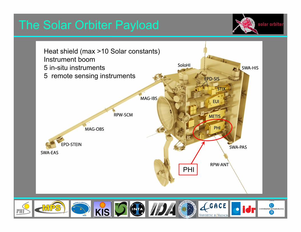
The Solar Orbiter Payload
PHI
Heat shield (max >10 Solar constants)Instrument boom5 in-situ instruments5 remote sensing instruments
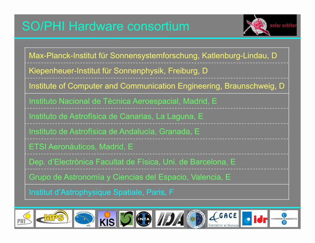
Max-Planck-Institut für Sonnensystemforschung, Katlenburg-Lindau, D
Kiepenheuer-Institut für Sonnenphysik, Freiburg, D
Institute of Computer and Communication Engineering, Braunschweig, D
Instituto Nacional de Técnica Aeroespacial, Madrid, E
Instituto de Astrofísica de Canarias, La Laguna, E
Instituto de Astrofísica de Andalucía, Granada, E
ETSI Aeronáuticos, Madrid, E
Dep. d’Electrònica Facultat de Física, Uni. de Barcelona, E
Grupo de Astronomía y Ciencias del Espacio, Valencia, E
Institut d’Astrophysique Spatiale, Paris, F
SO/PHI Hardware consortium

SO/PHI science
SO/PHI will probe the solar interior and provide the magnetic field at the solar surface that drives transient and energetic phenomena in the solar atmosphere and the heliosphere
Polarimetry and local helioseismology provided by SO/PHI will be central to reach 3 of the 4 top-level science goals of Solar Orbiter
SO/PHI will be the main instrument needed to answer the Solar Orbiter top-level science question: How does the solar dynamo work and drive connections between the Sun and the heliosphere?

SO/PHI Science
How and where does the solar wind plasma and magnetic field originate in the corona?
How do solar transients drive heliospheric variability?
How do solar eruptions produce energetic particle radiation that fills the heliosphere?
How does the solar dynamo work and drive connections between the Sun and the heliosphere?
PHI stand-alone science goals:- What is the nature of magnetoconvection?- How do active regions and sunspots evolve?- What is the global structure of the solar magnetic field?- How strongly does the solar luminosity vary and what is the source of
these variations?
Q1:
Q2:
Q3:
Q4:
Q5:

Atmospheric Coupling
SO is designed to probe the Sun from its interior up to the heliosphere.
SO with both remote sensing and in-situ measurements aims to address the largely unsolved problems of the origin of the solar wind as well as transport phenomena in the heliosphere
SO/PHI will provide the photosphericmagnetic field structure, i.e. an essential boundary condition needed to achieve these goals
Marsch et al., 2004

Stereoscopy and Global Sun
Tadesse et al., 2014
Vantage points far from Earth allow for near instantaneous 4 magnetic maps
HMI movie: 4.-17.9.2014
SO’s trajectory will allow doing Stokes stereoscopy, i.e. determining Stokes profiles of a feature from two different directions. Allows resolving the 180∘ ambiguity of Zeeman effect
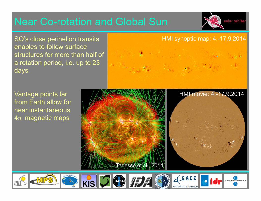
Near Co-rotation and Global Sun
Tadesse et al., 2014
SO’s close perihelion transits enables to follow surface structures for more than half of a rotation period, i.e. up to 23 days
Vantage points far from Earth allow for near instantaneous 4 magnetic maps
HMI synoptic map: 4.-17.9.2014
HMI movie: 4.-17.9.2014
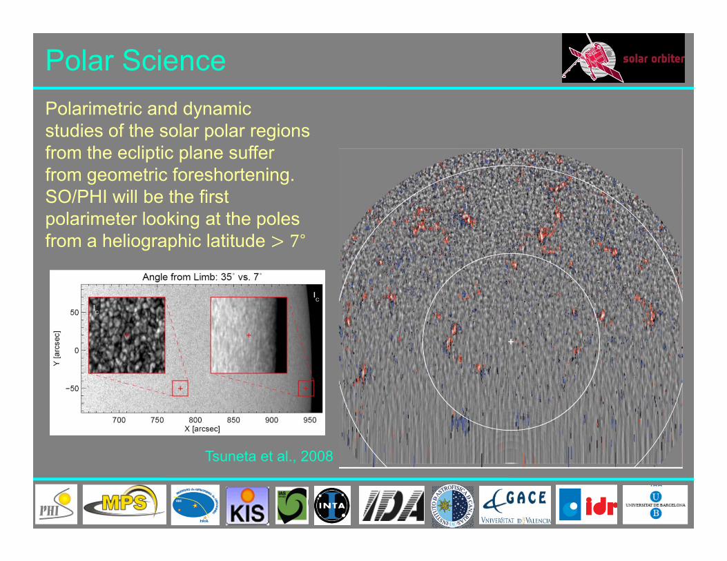
Polar Science
Tsuneta et al., 2008
Polarimetric and dynamic studies of the solar polar regions from the ecliptic plane suffer from geometric foreshortening. SO/PHI will be the first polarimeter looking at the poles from a heliographic latitude 7∘

Science Phases (NMP, EMP):3 Remote Sensing Windows (10 days each) per orbit: perihelion, min. and max. latitude (tbd)
Cruise Phase:2 instrument check-outs per year
NECP:Instrument commissioning
LEOP:SO/PHI is off
Operations (I)

Operations (II)
High latitude RSW
Low latitude RSW
Perihelion RSW
Outside RSW SO/PHI will carry out onboard data analysis: Raw data have to be kept in memory (4 Tbits internal memory size) Post-facto data selection for an efficient use of limited Telemetry Baseline concept, however, disallows long-term observations

SO/PHI Measurement Principle
PHI is a tunable imaging filtergraph:
Scans over a magnetic sensitive photosphericabsorption line (FeI 617.3nm)
Narrow-band filtergrams at 6 spectral positions
Full polarimetricinformation
On-board data processing & inversion
solar spectrum
PHI tunable passband
PHI order sorter
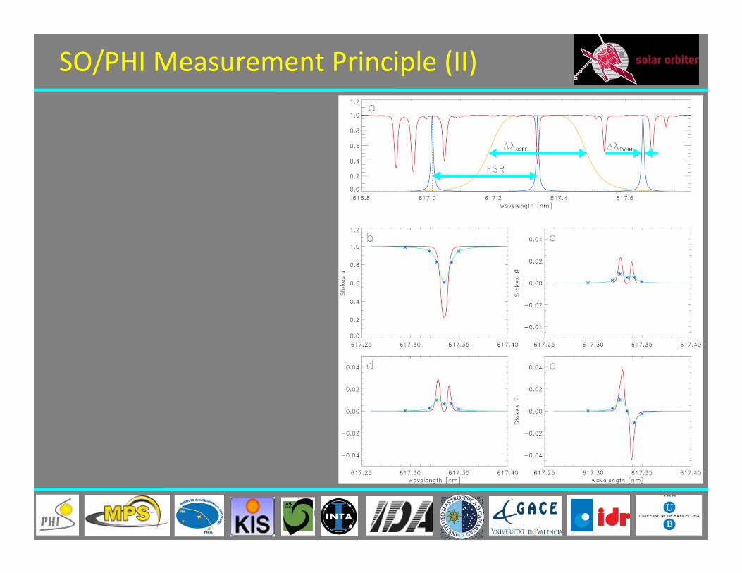
SO/PHI Measurement Principle (II)
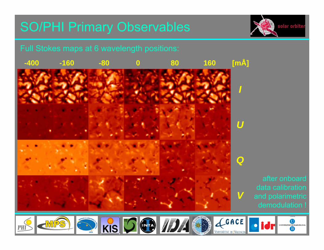
SO/PHI Primary Observables
-400 -160 -80 0 80 160 [mÅ]
I
U
Q
V
Full Stokes maps at 6 wavelength positions:
after onboard data calibration
and polarimetricdemodulation !

PHI data products:
PHI requirements: high-resolution data full-disk data 2k x 2k FOV 1 data set per minute
SO/PHI Data Products
Dynamic range
Noise
continuum intensity, Ic - ≤ 10-3
LOS velocity, vLOS ±5km/s ≤ 40m/sLOS magnetic field strength, BLOS ±3.5kG 15 Gmagnetic field inclination, γ 180° 1°magnetic field azimuth, φ ±180° 2°

SO/PHI Field of Views
Two Telescopes:
Full Disk Telescope:• FoV ~ 2°• Resolution ~3.5 arcsec per pixel• Full disk at all orbit positions• 17 mm aperture diameter
High Resolution Telescope:• FoV ~ 16 arcmin• Resolution: 0.5 arcsec per pixel• Resolution: ~200 km at closest
perihelion• 140 mm aperture diameter
HRT FoV
FDT FoV

SO/PHI Functional Diagram (simplified)
4 Mechanisms1 Active mirror
2x2 Tunable LCVRs1 Tunable etalon
2 APS cameras2 Entrance windows2 Telescopes
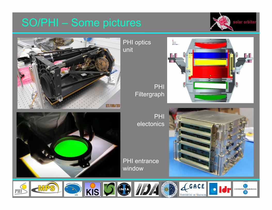
SO/PHI – Some picturesPHI optics unit
PHI Filtergraph
PHI electonics
PHI entrance window
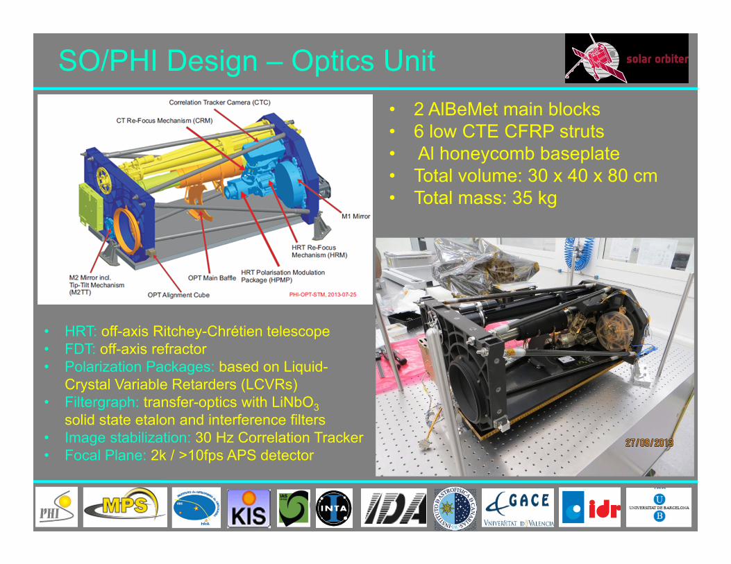
SO/PHI Design – Optics Unit• 2 AlBeMet main blocks • 6 low CTE CFRP struts• Al honeycomb baseplate• Total volume: 30 x 40 x 80 cm• Total mass: 35 kg
• HRT: off-axis Ritchey-Chrétien telescope• FDT: off-axis refractor • Polarization Packages: based on Liquid-
Crystal Variable Retarders (LCVRs)• Filtergraph: transfer-optics with LiNbO3
solid state etalon and interference filters• Image stabilization: 30 Hz Correlation Tracker • Focal Plane: 2k / >10fps APS detector

SO/PHI Design – Electronics Unit
High Voltage Power Supply
Analog Motor and Heater Drivers
Tip-Tilt Controller & Memory Board
Digital Processing Unit
Power Converter Modules
(redundant & main)
PCMtop-view

New and Critical Technologies
• Line scanning: first ever solid-state etalon in space (LiNbO3) • Polarization modulation: space-qualification of LCVRs for SO• Science detector: custom made APS sensor development• Heat rejection windows: optical/polarimetric performance between 0.28
and 0.9 AU • Data processing:
- use of powerful reconfigurable FPGAs- autonomous onboard calibration and data
processing (including inversion)
Most critical issue:Low Telemetry: 6.4 GBytes per orbit ≈ 100 GBytes over entire
mission lifetime

Conclusions
• SO/PHI is an extremely complex instrument on a highly ambitious space mission.
• SO/PHI has incorporated a series of new technologies which have to be functionally proven
• SO/PHI is an essential instrument to achieve the SO science goals -the SO/PHI instrument concept and design allows addressing a number of fundamental problems in solar physics
• The current status of SO/PHI is solid, however, schedule issues have to be tackled
• The entire SO mission suffers from the extremely limited telemetry. SO/PHI is one of the most telemetry starved instrument of the scientific payload. Additional telemetry has been requested

23 - 10 = 13 SLIDES
REDUCE TO 10-12!!!!BUT FIRST CHECK AVAILABLE TIME
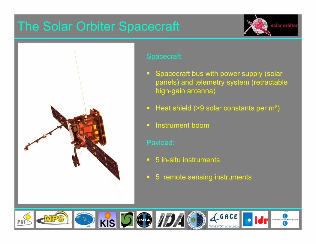
The Solar Orbiter Spacecraft
Spacecraft:
Spacecraft bus with power supply (solar panels) and telemetry system (retractable high-gain antenna)
Heat shield (>9 solar constants per m2)
Instrument boom
Payload:
5 in-situ instruments
5 remote sensing instruments

Helioseismology with SO/PHI
Stereoscopic Helioseismology
Probing the Sun from different vantage points may allow for probing deeper layers than what is possible with only one instrument.
Observations from a vantage point in the ecliptic does not allow probing solar latitudes higher than ~70°.SO/PHI observations from out of the ecliptic will help to accomplish the unsolved problems of, e.g., the solar dynamo.

SO/PHI Nominal Observations Mode Telescope FDT HRTImage size 2048 x 2048 2048 x 2048 Resolution 3.5”/pixel 0.5”/pixelCadence 60s 60 sParameters Ic,BLOS,γ, φ, vLOS Ic,BLOS,γ, φ, vLOS
Digital depths 10 bits (Ic,BLOS,vLOS), 8bits (γ, φ)
• Each data set requires 2048^2 x 46 = 184 Mbits• Compression by a factor of 2 gives 92Mbits per
data set Telemetry allocation allows only for ~500 data sets
per orbit!
In addition SO/PHI requires:• Calibration data• Raw data (sporadic)• Overhead (file headers, housekeeping, etc.)

Science Prospects Owing to the low telemetry and the baseline operation concept (only 3 Remote Sensing Windows per orbit) the achievement of the SO science goals will be highly insecure:
• Progress on the dynamo requires long-term/high-cadence observations (feature tracking, helioseismology)
• Solar wind/heliospheric science requires long term synoptic observations
The variable environment along the orbit will requires additional effort and resources for instrument calibration, which will stress the limited telemetry allocation:
• Re-calibration intervals will be short (at least prior to each RSW)• Onboard data processing requires ground checks of calibration
results• Sporadic downlink of raw data will secure smoothness onboard
data processing and will allow for advanced processing procedures

SO/PHI Synoptic Mode - proposed
• Full-disk data sets:‐ Continuum intensity‐ Magnetic field vector‐ Dopplergram (tbc)
• 1-4 data sets per day or longitude interval• 1k x 1k maximum size (rebinning for d < 0.5 AU)
Magnetogram Continuumintensity

SO/PHI Helioseismology - proposedHigh-cadence (~1min) Dopplergrams interlaced by synoptic observations
Time series: 1 - 100 days (and more) 80-90% duty cycle
Image sizes between 128 x128 and 2048 x 2048 pixels
Global (full-disk) and local (high-resolution) helioseismology observations intended
Most efficient data compression strategy is under investigation
FDT HRTDopplergrams
(e.g. Löptien et al. 2014)

Heat Rejection Entrance Windows
UV mirror
IR shield
617nm hi-pass
617nm lo-pass
Sun
PHI
space-side temperature model
at perihelion
HRT-HREW STM2
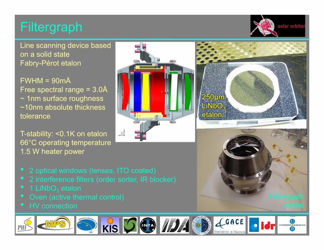
Filtergraph
Filtergraphmodel
250μmLiNbO3etalon
• 2 optical windows (lenses, ITO coated)• 2 interference filters (order sorter, IR blocker)• 1 LiNbO3 etalon• Oven (active thermal control)• HV connection
Line scanning device based on a solid state Fabry-Pérot etalon
FWHM = 90mÅFree spectral range = 3.0Å~ 1nm surface roughness~10nm absolute thickness tolerance
T-stability: <0.1K on etalon66°C operating temperature1.5 W heater power

Focal Plane Assembly
• 2k x 2k read-out at > 10fps
• FWC: 100ke- (<1% linearity)
• Actively cooled sensor (cold
element) => dark noise: ~100 e-/s
per pixel
• Automatic Single Event Upset
(SEU) recovery
• Automatic sensor Single Event
Latch-up (SEL) detection and
recovery (sensor power cycle)EFM FPA
sensor board
FPA FPGA board

Digital Processing Unit
Most critical items:2 reconfigurable FPGAs for onboard data analysis, image acquisition and CT control
Tasks:• Instrument control• Science data Acquisition
with >10 fps• Correlation Tracker control• Onboard data calibration• Onboard data inversion• 4 Tbits flash memory
control• Commanding/Telemetry

On-board Data Processing
36
FPA
Image Accumulation
Pixel Binning
PSF Deconvolution
Additional Correction
Polarization Demodulation
Cross-talkCorrection
Flat & DarkCorrection
Standard data pipeline
Optional processing steps
Additional paths (calibration, commissioning, etc.)
Data Pre-Processing:

On‐board Data Processing (contd.)
37
S/C
RTE Bit truncationCompression
Classical Processing
4 TbitFlash memory
TelemetryPacketting
Inversion and Compression:

Solar Orbiter Science CasesHow and where does the solar wind plasma and magnetic field originate in the corona?
How do solar transients drive heliospheric variability?
How do solar eruptions produce energetic particle radiation that fills the heliosphere?
How does the solar dynamo work and drive connections between the Sun and the heliosphere?
Q1:
Q2:
Q3:
Q4:


