
Spartan™-3A / Spartan™-3ANStarter Kit Pre-Loaded DemoEric CrabillXilinx, Incorporated04/01/2007
Agenda• How to set up the demonstration• How to operate the demonstration• Evaluating MultiBoot• Evaluating Suspend• Demo technical details

Demonstration Setup (1)• Make sure power switch is
turned off; connect power supply to circuit board
• Make sure suspend switchis set to run
• Connect suitable VGA display device to board– CRT– Projector– Flat panel
• Connect headphones or amplified speakers
Power Jackand Switch
VGAPort
AudioJack
SuspendSwitch

Demonstration Setup (2)• Optional: Connect PS/2
keyboard to the board• Optional: Connect serial
cable between board and PC, start the provided HyperTerminal session
PS/2Keyboard
RS232Cable

Demonstration Setup (3)• Optional: Install meters
for current measurement (meters not provided)– Meters must be set to
200mA or higher range– Meters must be on before
board power is applied– Reverse connections if
values shown during operation are negative VCCAUX and VCCINT
shunts removed to accommodate meters

Demonstration Setup (4)• Turn on power
– Audio and video output generation begins
– Messages are sent to the on-board LCD and the serial port
• Several forms of user interaction are possible– Manipulate image in real time– MultiBoot to other designs– Enter and exit Suspend You may need to adjust display device settings
(horizontal and vertical position) to center the display

How to Operate• There are different ways to “operate” the demo
– Switches and buttons, while viewing the VGA output– Switches and buttons, while viewing the LCD output– Through the RS232 port, using HyperTerminal on PC
• Although the demo setup states that the VGA display is required, you can run a demonstration by other means…

How to Operate (VGA - 1)• A menu is displayed at
the bottom of the display in blue text
• First, the MultiBoot menu– Spin knob to select next
configuration to load– Press any N/E/W/S button
to initiate MultiBoot– Press knob for next menu
press knob
press knob
press knob
pres
s kno
b
demo start

How to Operate (VGA - 2)• Image control menu 1
– Press N/E/W/S buttons to scroll displayed image
– Spin knob to rotate image – Press knob for next menu
• The “autopilot” (automatic demo) will stop if the user performs manual image transformations
press knob
press knob
press knob
pres
s kno
b
demo start

How to Operate (VGA - 3)• Image control menu 2
– Press N/E/W/S buttons to scroll displayed image
– Spin knob to scale image – Press knob for next menu
• The “autopilot” (automatic demo) will stop if the user performs manual image transformations
press knob
press knob
press knob
pres
s kno
b
demo start

How to Operate (VGA - 4)• Volume and Auto Menu
– Press any N/E/W/S button to resume the “autopilot”(automatic demo)
– Spin knob to adjust audio output volume (useful for headphones and speakers without volume control)
– Press knob to return to MultiBoot menu
press knob
press knob
press knob
pres
s kno
b
demo start

How to Operate (LCD)• When the demo begins, it
sends a greeting to the LCD for 1 second
• Next, a MultiBoot menu– Spin knob to select next
configuration to load– Press any N/E/W/S button
to initiate Multi-Boot• LCD menu tracks VGA
menu but only shows MultiBoot options
press knob
press knob
press knob
pres
s kno
b
wait 1 second
demo start
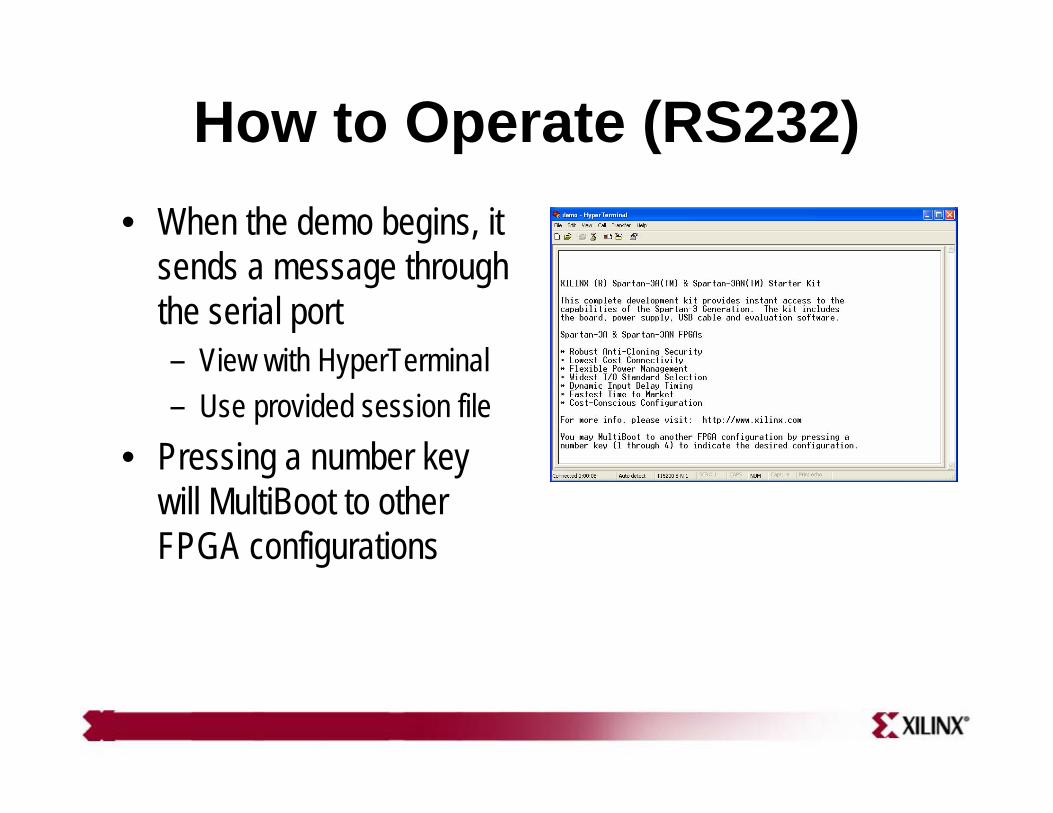
How to Operate (RS232)• When the demo begins, it
sends a message through the serial port– View with HyperTerminal– Use provided session file
• Pressing a number key will MultiBoot to other FPGA configurations

Evaluating MultiBoot• Use the MultiBoot menu to select from one of the
four additional FPGA configurations• The LCD and RS232 outputs allow MultiBoot
without the use of an attached VGA display• To return to the demo from any of the additional
FPGA configurations, press the rotary knob

Evaluating MultiBoot• Configuration 1
– DeviceDNA reader design– Provided by Ken Chapman, Xilinx– Reads Spartan-3A / Spartan-3AN identifier and displays on LCD– For more information, please download the original reference
design on the Spartan-3A Starter Kit Reference Design Page• Configuration 2
– Fractal generator design– A user-contributed design by Matthias Alles – Computes image in real time and displays on VGA– Rotate knob to zoom, press N/E/S/W buttons to scroll– For more information, please download the original design
from http://www-user.rhrk.uni-kl.de/~alles/fpga/

Evaluating MultiBoot• Configuration 3
– ASCII Terminal– Provided by Eric Crabill, Xilinx– Implements a terminal using a VGA display and PS/2 keyboard
and will communicate with HyperTerminal on a PC– For more information, consult the provided design source
• Configuration 4– Parallel Flash Programmer– Provided by Ken Chapman, Xilinx– Enables user to exercise, erase, and program the parallel flash
device on the board through HyperTerminal on a PC– For more information, please download the original reference
design on the Spartan-3A Starter Kit Reference Design Page

Evaluating Suspend• All five of the designs may be suspended at any time
– Observe demo state and optional metersprior to entering suspend
– Move suspend switch to suspend; observe optionalmeters and note supply current reduction
– Move suspend switch to run; observe that demostate has been preserved during suspend
• Do not suspend the flash programmer during a flash memory operation!

Demo Technical Details• In the main demo, a PicoBlaze processor
evaluates user inputs and programs thehardware peripherals to generate outputs– Video text from character mode video controller– Video bitmaps stored in parallel flash, and
transformed using “rotozoom” (resampling)– Audio waveforms stored in serial flash, played
back using digital I/O with XAPP154 technique– Other peripherals include ICAP-based MultiBoot
controller and hardware trigonometric function

Demo Block Diagram

Tech: PicoBlaze / UART• These modules were obtained from the Xilinx
website, http://www.xilinx.com/picoblaze and are not included in the source download
• The primary function of PicoBlaze is to drive the hardware based on user inputs– Demo program is stored in a single BlockRAM– Excellent “programmed” alternative to an FSM
• UARTs are used for serial port communication

Tech: Video Generation• PicoText is a video timing controller and character
display generator that accepts images from the rotozoom hardware (data stored in parallel flash)
• May be programmed on-the-fly to virtualize the character display hardware– Reduces buffer size by eliminating storage
of characters to represent “empty space”– Uses interrupt to advance the active region ahead
of the raster; programmed by a display list storedin the character buffer

Tech: Audio Generation• PicoTune is a simple audio controller that plays
back stored audio waveforms from SPI flash– Data is retrieved in a burst during vertical blank while
graphics fetch for rotozoom is idle; all flash memories on board share a data line
– Buffered data is consumed at sample rate by PWM audio output scheme based on Xilinx XAPP154

Tech: PicoBoot• PicoBoot is a simple counter-based ICAP
interface which may be programmed with MultiBoot parameters by the processor– Internal mode, internal use, address, etc…– Single strobe event initiates MultiBoot
• For details on the ICAP command and data sequences, consult the Spartan-3 GenerationConfiguration User Guide

Tech: Lookup Tables• Two large lookup tables are implemented
– AutoPilot ROM stores a table of “scripted” userinputs to control the demonstration in the absenceof interactive user input
– Polar to Rectangular converter consists of a sin(x)/cos(x) table followed by a multiplier to implement magnitude scaling; used to convertangle and step size (scale) into delta x,y valuesfor rotozoom hardware

Tech: User and LCD• User interface consists of quadrature decoder for
rotary knob, plus synchronizers and debouncersfor ordinary buttons
• LCD interface is effectively general purpose I/O controlled by software to drive this display


