
Spatial Note System:
Combining the Advantages of SNS and
Traditional Note
44171656-5 Zhinan LI
Supervisor: Prof. Jiro TANAKA
Graduate School of Information, Production and Systems
Waseda University
A thesis submitted for the degree of
Master of Engineering
July 2019
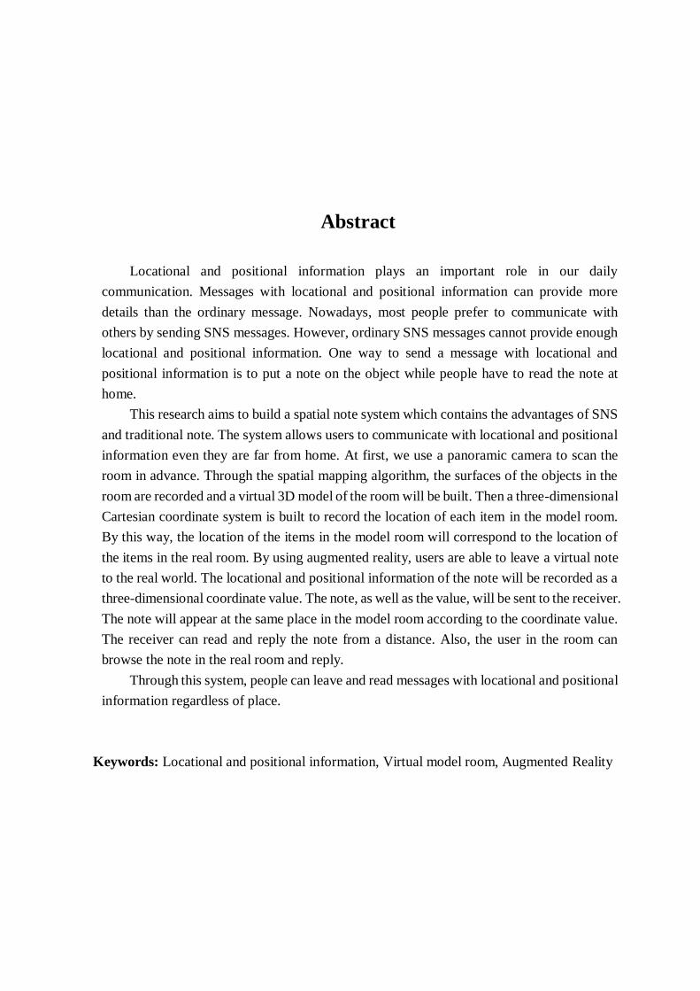
Abstract
Locational and positional information plays an important role in our daily
communication. Messages with locational and positional information can provide more
details than the ordinary message. Nowadays, most people prefer to communicate with
others by sending SNS messages. However, ordinary SNS messages cannot provide enough
locational and positional information. One way to send a message with locational and
positional information is to put a note on the object while people have to read the note at
home.
This research aims to build a spatial note system which contains the advantages of SNS
and traditional note. The system allows users to communicate with locational and positional
information even they are far from home. At first, we use a panoramic camera to scan the
room in advance. Through the spatial mapping algorithm, the surfaces of the objects in the
room are recorded and a virtual 3D model of the room will be built. Then a three-dimensional
Cartesian coordinate system is built to record the location of each item in the model room.
By this way, the location of the items in the model room will correspond to the location of
the items in the real room. By using augmented reality, users are able to leave a virtual note
to the real world. The locational and positional information of the note will be recorded as a
three-dimensional coordinate value. The note, as well as the value, will be sent to the receiver.
The note will appear at the same place in the model room according to the coordinate value.
The receiver can read and reply the note from a distance. Also, the user in the room can
browse the note in the real room and reply.
Through this system, people can leave and read messages with locational and positional
information regardless of place.
Keywords: Locational and positional information, Virtual model room, Augmented Reality
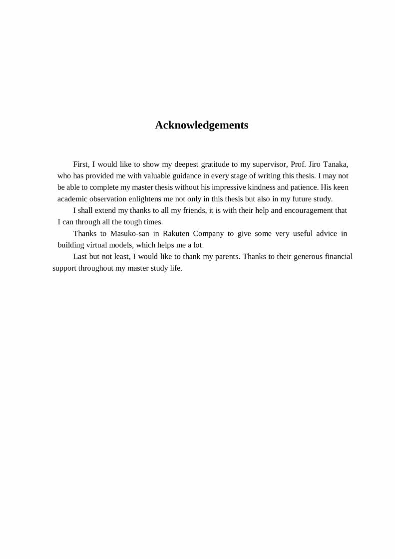
Acknowledgements
First, I would like to show my deepest gratitude to my supervisor, Prof. Jiro Tanaka,
who has provided me with valuable guidance in every stage of writing this thesis. I may not
be able to complete my master thesis without his impressive kindness and patience. His keen
academic observation enlightens me not only in this thesis but also in my future study.
I shall extend my thanks to all my friends, it is with their help and encouragement that
I can through all the tough times.
Thanks to Masuko-san in Rakuten Company to give some very useful advice in
building virtual models, which helps me a lot.
Last but not least, I would like to thank my parents. Thanks to their generous financial
support throughout my master study life.

Table of contents
List of figures
List of tables
1 Background
1.1 Augmented Reality ......................................................................................3
1.2 3D Scanning ................................................................................................4
1.3 Organization of the Thesis ...........................................................................5
2 Research Goal and Approach
2.1 Problem ....................................................................................................... 6
2.2 Research Goal.............................................................................................. 7
2.3 Research Approach ...................................................................................... 7
3 System Design
3.1 System Overview ......................................................................................... 9
3.2 Room Scanning ......................................................................................... 10
3.3 Making Note .............................................................................................. 11
3.4 Record Position Information ...................................................................... 13
3.5 Send Note and Position Information........................................................... 14
3.6 Replying Notes .......................................................................................... 15
3.7 Two-way information transmission ............................................................ 18
3.8 Usage Scenario .......................................................................................... 19
3.8.1 Persona and Frustration ................................................................. 19
3.8.2 Possible Scenario ................................................................................. 19
4 System Implementation
4.1 Development Environment ........................................................................ 21
4.2 Hardware Overview ................................................................................... 21
4.2.1 Google Pixel 2 .............................................................................. 21
4.2.2 Personal Computer .............................................................................. 22
4.2.3 RICOH THETA V ............................................................................... 23
4.3 Implementation of Room Scanning ............................................................ 24
4.3.1 HR Image Capture ........................................................................ 24
4.3.2 Panorama Picture ................................................................................. 24
4.3.3 Image Reconstruction .......................................................................... 24
4.4 Implementation of Making Note ................................................................ 31
4.4.1 Plane Detection .................................................................................... 31
4.4.2 Collision Detection .............................................................................. 32
4.5 Implementation of Recording locational information ................................. 34
4.6 Implementation of Information Transfer .................................................... 36
5 Related Work
5.1 Related Works on Room Scanning ............................................................. 38
5.2 Related Works on Leaving Virtual Note .................................................... 39
6 Evaluation
6.1 Participants ................................................................................................ 42
6.2 Method ...................................................................................................... 42
6.3 Result ........................................................................................................ 44
7 Conclusion
7.1 Summary ................................................................................................... 47
7.2 Future Work .............................................................................................. 48
References
Appendix
List of figures
2.1 Examples of leave and read message ............................................................. 8
3.1 Room Scanning ........................................................................................... 10
3.2 A panorama picture ..................................................................................... 11
3.3 Detected Plane ............................................................................................ 12
3.4 Leave a “Hello World” note ........................................................................ 12
3.5 Three-dimensional Cartesian coordinate system .......................................... 13
3.6 Position information of the note .................................................................. 14
3.7 Position information in the virtual model room ............................................ 15
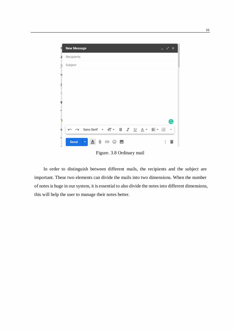
3.8 Ordinary mail .............................................................................................. 16
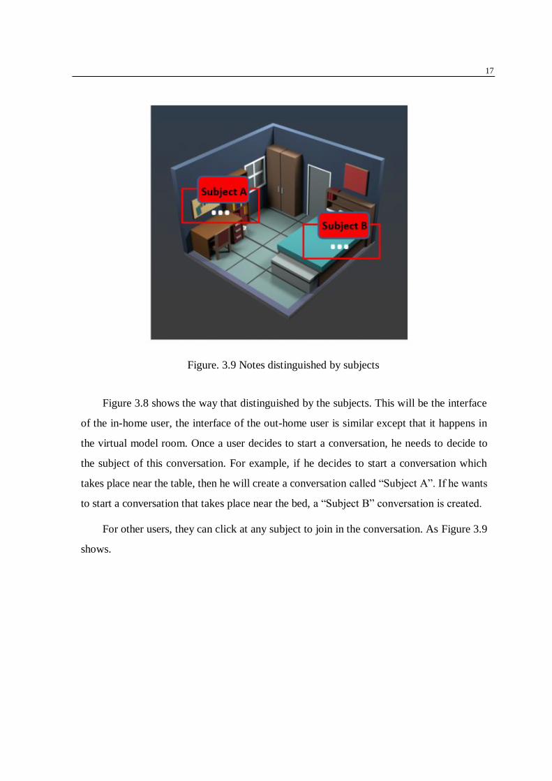
3.9 Notes distinguished by subjects ................................................................... 17
3.10 Notes distinguished by senders .................................................................... 18
4.1 Google Pixel 2 ............................................................................................. 22
4.2 RICOH THETA V....................................................................................... 23
4.3 Meshroom ................................................................................................... 25
4.4 Import images.............................................................................................. 26
4.5 Chapters of the whole pipeline ..................................................................... 27
4.6 CameraInit................................................................................................... 27
4.7 FeatureExtraction ........................................................................................ 27
4.8 ImageMatching ........................................................................................... 28
4.9 FeatureMatching.......................................................................................... 28
4.10 StrcutureFromMotion .................................................................................. 28
4.11 PrepareDenseScene ..................................................................................... 29
4.12 DepthMap ................................................................................................... 29
4.13 DepthMapFilter ........................................................................................... 29
4.14 Meshing ...................................................................................................... 30
4.15 MeshFiltering .............................................................................................. 30
4.16 Texturing ..................................................................................................... 30
4.17 Import the ARCore SDK ............................................................................. 32
4.18 Code that detect plane.................................................................................. 32
4.19 Code that detect collision ............................................................................. 34
4.20 Code that detect collision ............................................................................. 34
4.21 Users send note with positional information ................................................ 37

4.22 Users receive notes with positional information ........................................... 37
6.1 Convenience Comparison of Sending Message .............................................. 45
6.2 Comparison of the Quantity of Explanation ................................................... 45

List of tables
4.1 The information of Google Pixel 2 .................................................................. 22
4.2 The information of PC ................................................................................... 23
4.3 The information of RICOH THETA V ............................................................ 24
6.1 Subject Demographic Information .................................................................. 42
6.2 Messages the participants sent ........................................................................ 43
6.3 Questionnaire for Using SNS ......................................................................... 43
6.4 Questionnaire for Using Our System............................................................... 44

Chapter 1
Background
1.1 Augmented Reality
Augmented reality is a technology that integrates real-world information with virtual
world information. It can simulate and emulate the physical information which was difficult
to experience in a certain time and space of the real world, and then superimpose and apply
the virtual information to the real world, which is perceived by human senses, thereby
achieving a sensory experience beyond reality.
Augmented reality is not a new concept. The word “augmented reality” was first
proposed by Thomas P. Caudell, a former Boeing researcher [1]. In the following years, AR
began to slowly begin to show its talents in the professional field. One of the first functioning
AR system, the Virtual Fixtures, was developed at the United States Air Force Research
Laboratory by Louis Rosenberg [2]. Also in 1992, Steven Feiner, Blair MacIntyre, and
Doree Seligmann present a paper about an AR system prototype, KARMA, at the Graphics
Interface conference. But AR is still not a popular technology yet until the AR ToolKit
appears [3]. After that, with the release of more and more head-mounted AR devices and the
popularity of AR-enabled smartphones, AR technology is entering the field of more and
more people.
4
ARCore is a software development kit that allows for augmented reality applications
to be built [4]. ARCore uses different APIs to make the smartphone aware of its environment,
understand the real world [5]. It has three main technologies [6]:
• Motion tracking
• Environmental understanding
• Light estimation
Motion tracking allows the phone to understand and track its position relative to the
world. It will detect the feature points captured in the camera and use these feature points to
compute its change in location. This process is called concurrent odometry and mapping, or
COM.
Environmental understanding allows the phone to detect the size and location of various
surfaces. It can also detect the border of each plane so that the virtual objects are able to
place on a certain surface.
Light estimation allows the phone to estimate the current lighting conditions of the
environment.
1.2 3D scanning
3D scanning is the process of analyzing a real-world object or environment to collect
data on its shape and possibly its appearance. The collected data can then be used to
construct digital 3D models. The collected data can be used in a variety of applications, such
as construction industry, 3D photography, motion capture and augmented reality. 3D
scanning is also often used in the entertainment industry such as movies and games. To
create 3D digital models by scanning real objects. In the presence of real-world equivalent
models, scanning real-world objects is much faster than manually creating models using 3D
modeling software.

5
1.3 Organization of the Thesis
The rest of the thesis is organized as follows: In chapter 2, we will describe the problem
that we want to solve and the approaches that we use. In chapter 3 will introduce the whole
system design. In chapter 4is the system implementation part where the detailed environment
and implementation will be talked. In chapter 5 we will discuss some related works. At last,
chapter 6 will be the conclusion part.

Chapter 2
Research Goal and Approach
2.1 Problem
Communication plays an important role in our daily life. In the past, we usually write
letters or leave notes. With the development of technology, now the PC and the smartphone
is very popular. People’s way of communication has changed a lot. Nowadays, E-mail and
SNS messages become the most popular way to communicate with others.
In some informal occasions, sending an E-mail is unnecessary. For example, to
communicate with family members. In that case, sending SNS messages is very convenient.
People can send SNS messages anywhere and anytime. In addition, unless a paper letter or
note, it is not easy to lose. Therefore, family members and close friends usually prefer
sending SNS messages as their way of communication.
It seems that the SNS is perfect, but it still has one serious disadvantage. The messages
usually lack locational and positional information. It means when we send an SNS message,
it does not include the information of the current scene. Here is some possible scenario to
prove that how inconvenient it will be if the message is lack of locational and positional
information:
• The mother sends a message: “Do not forget to drink the milk.”, but the child does
not know where the milk is.
7
• The mother sends a message: “How about move the sofa to that corner?”, but the
father does not know which corner.
• The child sends a message: “I left your key in the living room.”, but the mother still
cannot find the key in the living room.
To provide locational and positional information, one traditional way is to paste sticky
notes on the objects. The note not only provides the contents information but also the
locational information. By this way, the communication is simpler. However, the notes must
be read at the places where they were pasted. If people are not at home, they cannot read the
notes. Besides, sticky notes are easy to lose. This is the problem we want to solve.
2.2 Research Goal
In this research, we aim to build a system which combines the advantages of SNS and
traditional notes. So that the system can:
• Leave and read the locational and positional supportive notes.
• Allow the user to leave and read the note regardless of places and time.
2.3 Research Approach
In this research, we build a spatial note system that allows the user to leave and read the
note in the real world by using augmented reality. The receiver who is not at home is able to
read and leave the note in the virtual model room.
At first, we scan the room using the depth camera in advance. Through the spatial mapping
algorithm, the surfaces of the objects in the room are recorded and a virtual 3D model of the
room will be built. Then a three-dimensional Cartesian coordinate system is built to record the
location of each item in the model room. By this way, the location of the items in the model
room will correspond to the location of the items in the real room.
Assume that user A wants to leave a note to user B who is not at home (See Fig 2.1). To
leave a note in the real room, we use Google ARCore. It detects the surrounding objects and

8
can add virtual notes on these objects. When A leaves a note, it is sent to B including positional
information. This note will appear at the same place in the virtual room. B can use his
smartphone to browse all the notes left in that virtual room. On the other hand, B can also leave
a note in the virtual room. The note will appear at the same place in the real room. A can use
his smartphone to read it.
.
Figure. 2.1 Examples of leave and read message

Chapter 3
System Design
3.1 System Overview
The system mainly contains two part. The in-home user part and the out-home user part.
The in-home user part allows users to leave a note message in the real world. The system
will detect the plane automatically and attach the note to the detected plane. The in-home
user can leave several notes in the room and the position of each note will be recorded. The
in-home user can also read and reply to the notes left by the out-home user. For the out-
home users, they cannot directly leave and read the note in the real world, but they can
indirectly leave the note to the virtual model room. The virtual model room is the miniature
of the real room. If the in-home user leaves a note at some certain place in the room, the out-
home user can read the room at the same place in the virtual model room.
By using this system, people can communicate with each other at any place and at any
time. For the in-home user, he can leave and receive a note by using smartphones in the real
room. For the out-home user, he can do the same thing in the virtual model room. Both the
in-home user and the out-home user can reply to the note they received.

10
3.2 Room Scanning
Figure. 3.1 Room Scanning
To make sure that the out-home user can also leave and read a note, the important thing
is to build a miniature for the real room. Figure 3.1 shows the operation of room scanning.
The locational and positional information of the real room is translated into the information
of the virtual room. Once a note is left in the real room, its location information is recorded.
Then the out-home user can know the position of the note by browsing the virtual room
model. the in-home user leaves a note at some certain place in the room, the out-home user
can read the room at the same place in the virtual model room.
We use a panorama camera to take several panoramas of the real room, as Figure 3.2
shows.

11
Figure. 3.2 A panorama picture
Then we will use image reconstruction to reconstruct 3D models.
After reconstructing, we need to export the reconstructing result. The result of the
scanning will be built into OBJ files. The OBJ file is a simple data format that represents
three-dimensional geometry, including the position of each vertex, the UV position, the
normal, and the list of vertices that make up the polygon. With the OBJ files, we can do
further operations.
3.3 Making Note
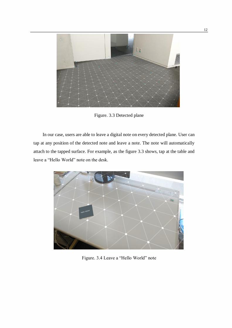
The system used ARCore as developing tools. It can detect planes. For example,
as the figure 3.2 shows, the floor of the room is detected. This will enable the users to
put several virtual objects on the plane.
12
Figure. 3.3 Detected plane
In our case, users are able to leave a digital note on every detected plane. User can
tap at any position of the detected note and leave a note. The note will automatically
attach to the tapped surface. For example, as the figure 3.3 shows, tap at the table and
leave a “Hello World” note on the desk.
Figure. 3.4 Leave a “Hello World” note
13
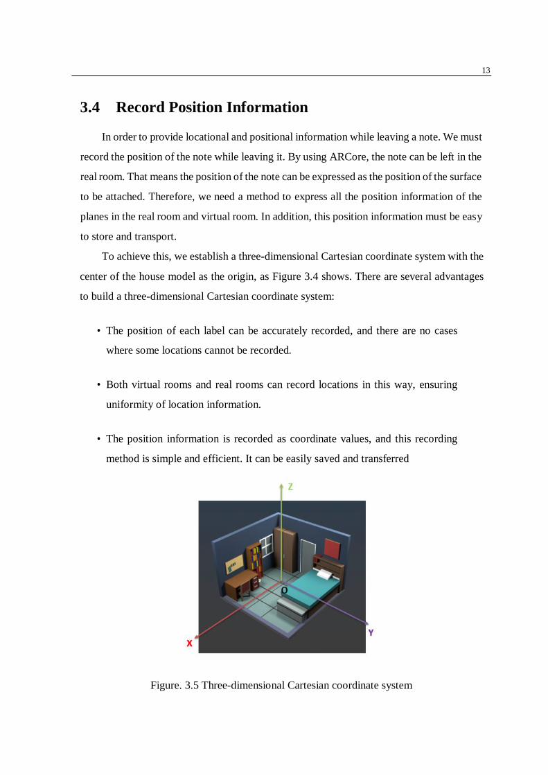
3.4 Record Position Information
In order to provide locational and positional information while leaving a note. We must
record the position of the note while leaving it. By using ARCore, the note can be left in the
real room. That means the position of the note can be expressed as the position of the surface
to be attached. Therefore, we need a method to express all the position information of the
planes in the real room and virtual room. In addition, this position information must be easy
to store and transport.
To achieve this, we establish a three-dimensional Cartesian coordinate system with the
center of the house model as the origin, as Figure 3.4 shows. There are several advantages
to build a three-dimensional Cartesian coordinate system:
• The position of each label can be accurately recorded, and there are no cases
where some locations cannot be recorded.
• Both virtual rooms and real rooms can record locations in this way, ensuring
uniformity of location information.
• The position information is recorded as coordinate values, and this recording
method is simple and efficient. It can be easily saved and transferred
Figure. 3.5 Three-dimensional Cartesian coordinate system

14
Figure 3.4 shows an example of how to record the locational and positional information
of note. Once the user tap at a certain place, the coordinate position of the tapped place is
recorded as a coordinate value.
Figure. 3.6 Position information of the note
For example, when the user taps at the desk. The system will detect that the coordinate
value of the note is (𝑥1, 𝑦1, 𝑧1). Then the content of the note, as well as the coordinate value,
is recorded. After that, it will be sent to the receiver.
3.5 Send Note and Position Information
After recording the position information, the content of the note and the position
information will be sent to the receiver. As well as the real room, the virtual model also has
a three-dimensional Cartesian coordinate system. The coordinate value of the virtual room
is in one-to-one correspondence with the coordinate value of the real room. So that
according to the coordinate position in the real room, the position of the note in the virtual

15
room is confirmed.
As Figure 3.6 shows. When a note with the coordinate value of (𝑥1, 𝑦1, 𝑧1) is left and
sent to the receiver, the out-home receiver will show the note in the virtual model room at
the same place.
Figure. 3.7 Position information in the virtual model room
3.6 Replying notes
In order to provide the user with complete communication experience. We also allow
the user to reply to the notes. Our system is more likely a mail system, the ordinary mail
system has several elements, just as figure 3.7 shows. Including the recipients, subject and
the contents.
16
Figure. 3.8 Ordinary mail
In order to distinguish between different mails, the recipients and the subject are
important. These two elements can divide the mails into two dimensions. When the number
of notes is huge in our system, it is essential to also divide the notes into different dimensions,
this will help the user to manage their notes better.
17
Figure. 3.9 Notes distinguished by subjects
Figure 3.8 shows the way that distinguished by the subjects. This will be the interface
of the in-home user, the interface of the out-home user is similar except that it happens in
the virtual model room. Once a user decides to start a conversation, he needs to decide to
the subject of this conversation. For example, if he decides to start a conversation which
takes place near the table, then he will create a conversation called “Subject A”. If he wants
to start a conversation that takes place near the bed, a “Subject B” conversation is created.
For other users, they can click at any subject to join in the conversation. As Figure 3.9
shows.

18
Figure. 3.10 Notes distinguished by senders
When we add another dimension, the senders, the system will clearer. Once a user adds
a note to a certain subject, his name will also show with the note. It is like a normal group
chat in ordinary SNS software. When user A add a note to “Subject A”, his note will occur
in this subject. When user B replies to A’s note, B’s note will occur under A’s. By this way,
we create a group conversation.
By dividing the note into these two dimensions above, users can easily find and read
notes.
3.7 Two-way information transmission
In addition to the user can send messages from the real room and receive from the
virtual room, the reverse is also possible. The out-home user can send messages from the
virtual model room, and the in-home user can receive the note in the real room. The process
is quite similar. The out-home user can tap at a certain place to leave a note. The coordinate
value in the virtual model room is recorded. After sending the note and the position
19
information, the in-home user will find that there will be a new note appear.
3.8 Usage Scenario
3.8.1 Persona and Frustration
• Mother: 44 years old, a businesswoman. She always leaves home at 7:00 and
goes back at 18:00.
• Father: 45 years old, a businessman. He always leaves home at 6:00 and goes
back at 17:00.
• Child: 12 years old, a student. He always leaves home at 8:00 and goes back at
15:00 during school days. Now he is during the summer vacation, so he does
not have to go to school. He usually gets up at 9:00 during vacations.
• Frustration: The families need to communicate with each other, but they cannot
meet with each other every time. Sometimes sending SNS messages cannot
explain their meanings perfectly.
3.8.2 Possible Scenario
• 5:30: The father gets up and has his breakfast. Today is the child’s birthday so
he prepares a surprise for him. He puts a present near the child’s bed while the
child is still sleeping. The father leaves home.
• 5:45: The father realizes that he wants to see how the child react when he opens
the present, so he uses his smartphone to leave a note “Do not open it until I get
home! It will be a big surprise!”.
• 6:00: The mother gets up and has her breakfast. She also makes breakfast for the
child. She leaves the breakfast on the table. After that, the mother leaves home

20
• 7:30: The mother is working. She suddenly realizes she forget to tell the child to eat the
egg in the refrigerator, so she leaves a note at the refrigerator: “Do not forget to eat the
egg!”.
• 9:00: The child gets up. He finds the present from his father, he also finds the
note, so he doesn’t open it.
• 9:30: The child is having his breakfast and he finds the note on the refrigerator,
so he eats the egg.
• 17:00: The father gets home. The child and father open the present together, the child
likes it very much, and he thanks his dad. The father is quite happy.
• 17:30: The mother realize they will have a birthday party at 18:30, but she forgets to
clean the desk in the living room, so she leaves a note at the table in the living room to
the father: “Clean this table before the party please, I forgot to do that.” The father finds
the note on the desk and clean it.
• 18:00: The mother gets home.
• 18:30: They have the birthday party.
21
Chapter 4
System Implementation
4.1 Development Environment
We use Microsoft Windows 10 as the developing environment. We use Unity 2017
and Visual Studio 2017 as the development tools. We use ARCore Unity SDK to realize
the augmented reality on the Android smartphone.
4.2 Hardware Overview
In our system, we mainly use three hardware. Google Pixel 2 as the Android smartphone,
the PC as the development device and the RICOH THETA V as the room scanning device.
4.2.1 Google Pixel 2
Android is an open source mobile operating system based on the Linux kernel. It is lead
and developed by the Open Handset Alliance which established by Google. It is primarily for
touchscreen mobile devices such as smartphones and tablets and other portable devices. By the
end of 2010, Android surpassed Nokia's Symbian operating system to become the world's
highest mobile operating system. In March 2017, Android global network traffic and devices
22
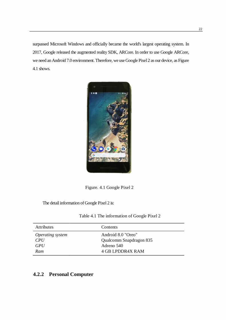
surpassed Microsoft Windows and officially became the world's largest operating system. In
2017, Google released the augmented reality SDK, ARCore. In order to use Google ARCore,
we need an Android 7.0 environment. Therefore, we use Google Pixel 2 as our device, as Figure
4.1 shows.
Figure. 4.1 Google Pixel 2
The detail information of Google Pixel 2 is:
Table 4.1 The information of Google Pixel 2
Attributes Contents
Operating system Android 8.0 "Oreo"
CPU Qualcomm Snapdragon 835
GPU Adreno 540
Ram 4 GB LPDDR4X RAM
4.2.2 Personal Computer

23
The PC is used as development tools. We use it to run the Unity 2017 and the
Visual Studio 2017. The PC is also used to deal with the picture that caught by the
camera. To run the reconstruction software, an Nvidia GPU is needed (with compute
capability of at least 2.0). The detail information of the PC we use is:
Table 4.2 The information of PC
Attributes Contents
Operating system Microsoft Windows 10
CPU Intel Core i7-7700K @4.2 GHz
GPU NVIDIA GeForce GTX 1080
Ram 16 GB
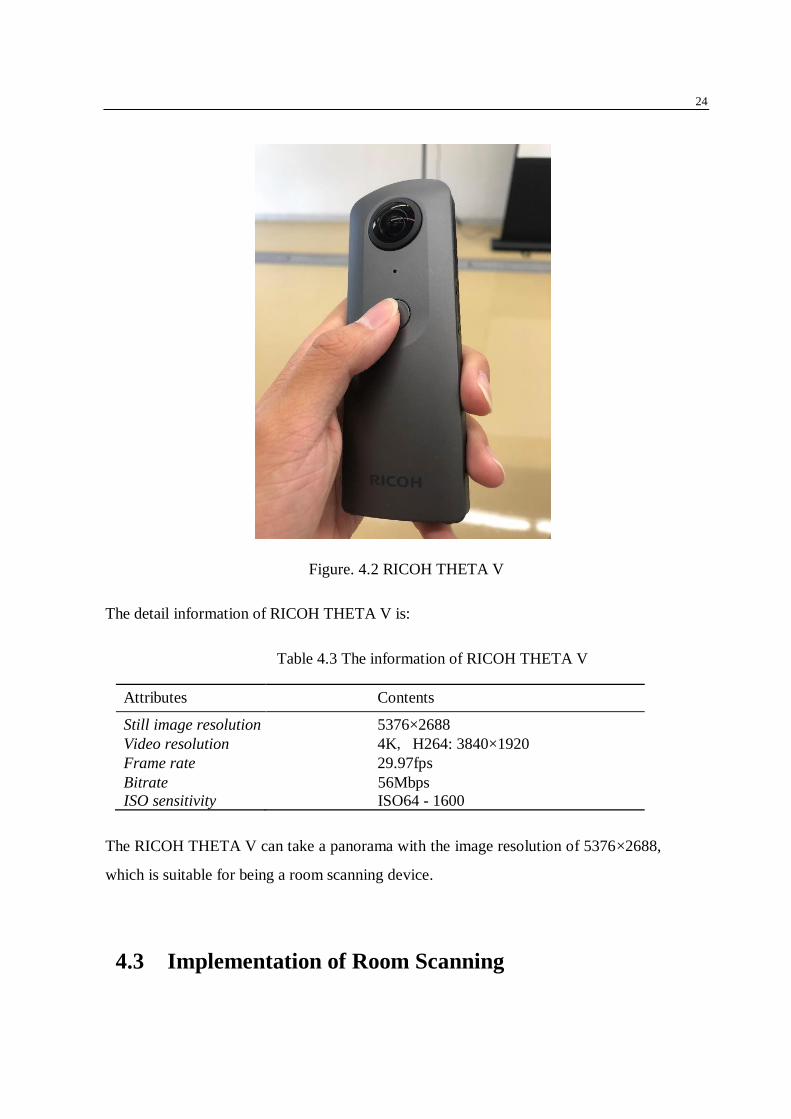
4.2.3 RICOH THETA V
We need a panoramic camera to take a panorama. To build a good room model,
we need high-quality pictures, so we use is RICOH THETA V. As Figure 4.1 shows.
24
Figure. 4.2 RICOH THETA V
The detail information of RICOH THETA V is:
Table 4.3 The information of RICOH THETA V
Attributes Contents
Still image resolution 5376×2688
Video resolution 4K, H264: 3840×1920
Frame rate 29.97fps
Bitrate
ISO sensitivity
56Mbps
ISO64 - 1600
The RICOH THETA V can take a panorama with the image resolution of 5376×2688,
which is suitable for being a room scanning device.
4.3 Implementation of Room Scanning
25
4.3.1 HR Image Capture
Image with high resolution (HR) always can contain more details than ordinary images .
For example, in my research, I need to reconstruct the image into 3D models which contain
depth information. In order to realize that. Image with high-quality is essential. Therefore,
to get high quality virtual models, I need a camera with the ability to take high-resolution
pictures.
4.3.2 Panorama Picture
To reconstruct a small size 3D model, ordinary HR picture is enough. However, to build
a big virtual model room. An ordinary 2D picture cannot capture all the information in the
room. Therefore, to get a full view picture, I need a camera with the ability to take high-
resolution pictures. Here I choose the RICOH THETA V. It can take 5376×2688 panorama
pictures.
4.3.3 Image Reconstruction
To do the reconstruction operation, we use a software called Meshroom. Meshroom is
a free, open-source 3D reconstruction software.
The first important part is shooting quality. It has a huge impact on the quality of the
final grid. Shooting is always compromised to fit the project's goals and constraints: scene
size, material properties, texture quality, shooting time, amount of light, varying light or
objects, camera device quality, and settings. The main goal is to get a clear image with no
motion blur and no depth blur.
Meshroom is designed to get a 3D model from multiple images with the minimal user
action. For this reason, Meshroom relies on a nodal system which exposes all the
photogrammetry pipeline steps as nodes with parameters. The high-level interface above
this allows anyone to use Meshroom without the need to modify anything. Figure 4.3 shows
the interface of Meshroom.

26
Figure. 4.3 Meshroom
The first step is to save the project on the disk. After that, we import images into this
project by dropping them in the “images” area. The metadata of the images will be analyzed.
Then the scene will be set up. See Figure 4.4.
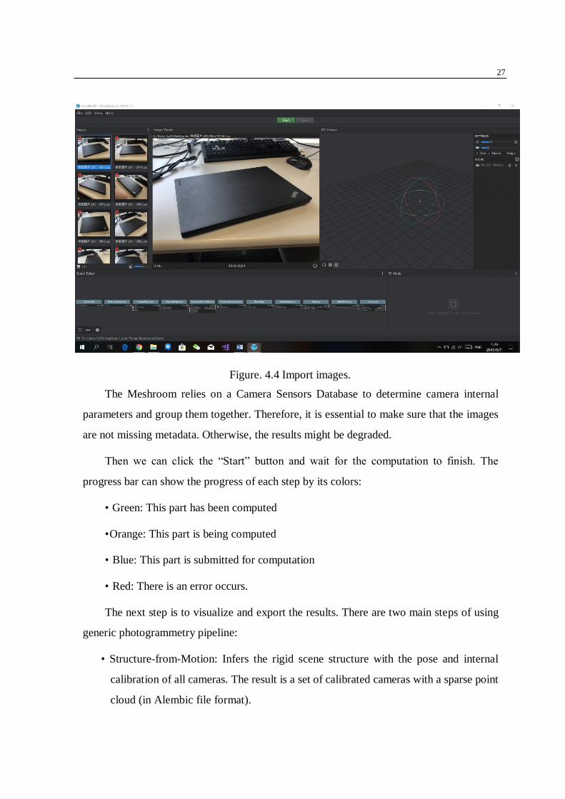
27
Figure. 4.4 Import images.
The Meshroom relies on a Camera Sensors Database to determine camera internal
parameters and group them together. Therefore, it is essential to make sure that the images
are not missing metadata. Otherwise, the results might be degraded.
Then we can click the “Start” button and wait for the computation to finish. The
progress bar can show the progress of each step by its colors:
• Green: This part has been computed
• Orange: This part is being computed
• Blue: This part is submitted for computation
• Red: There is an error occurs.
The next step is to visualize and export the results. There are two main steps of using
generic photogrammetry pipeline:
• Structure-from-Motion: Infers the rigid scene structure with the pose and internal
calibration of all cameras. The result is a set of calibrated cameras with a sparse point
cloud (in Alembic file format).
28
• MultiView-Stereo: Uses the calibrated cameras from the Structure-from-Motion to
generate a dense geometric surface. The final result is a textured mesh.
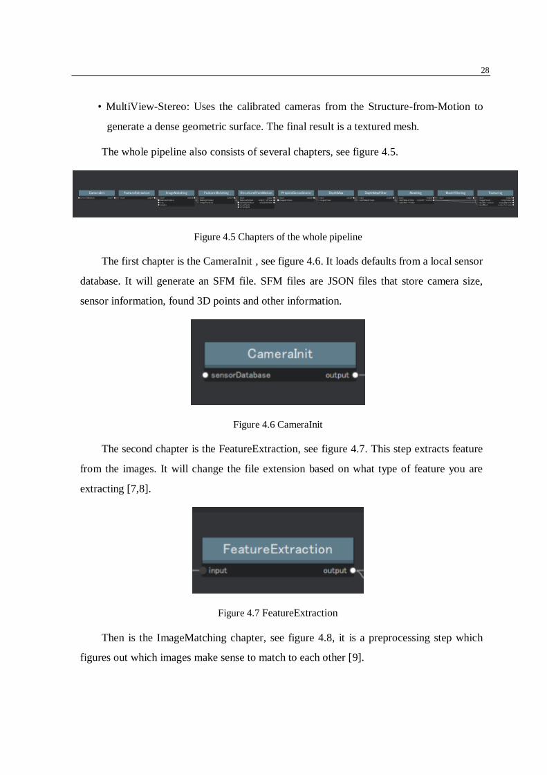
The whole pipeline also consists of several chapters, see figure 4.5.
Figure 4.5 Chapters of the whole pipeline
The first chapter is the CameraInit , see figure 4.6. It loads defaults from a local sensor
database. It will generate an SFM file. SFM files are JSON files that store camera size,
sensor information, found 3D points and other information.
Figure 4.6 CameraInit
The second chapter is the FeatureExtraction, see figure 4.7. This step extracts feature
from the images. It will change the file extension based on what type of feature you are
extracting [7,8].
Figure 4.7 FeatureExtraction
Then is the ImageMatching chapter, see figure 4.8, it is a preprocessing step which
figures out which images make sense to match to each other [9].

29
Figure 4.8 ImageMatching
Then is the FeaturMathing chapter, see figure 4.9, it is to find the correspondence
between the images, using feature descriptors. The generated text files are self-explanatory
[10].
Figure 4.9 FeaturMathing
Then is the StructureFromMotion chapter, see figure 4.10. This step is to understand
the geometric relationship behind all the observations provided by the input images and infer
the rigid scene structure with the pose and internal calibration of all cameras [11].
Figure 4.10 StructureFromMotion
Next chapter, PrepareDenseScene [12], see figure 4.11, is to undistort the images. It
generates undistorted EXR images so that the following depth calculation and projection
steps do not have to convert back and forth from the distortion function.

30
Figure 4.11 PrepareDenseScene
Next step is DepthMap [13], see figure 4.12, this step is to retrieve the depth value of
each pixel from all the cameras that have been resolved by SFM. The original depth maps
will not consistent. Therefore, we need the next step.
Figure 4.12 DepthMap
The DepthMapFilter step isolates the area that is occluded by other depth maps and
forces depth consistency [14], see figure 4.13.
Figure 4.13 DepthMapFilter
The Meshing [15] step is to create a dense geometric surface representation of the scene,
see figure 4.14.

31
Figure 4.14 Meshing
The MeshingFiltering [16] chapter takes the previous chapter mesh and applies some
refinements, like smoothing the mesh, removing the large triangles and keeping the largest
mesh but removing all the others, see figure 4.15.
Figure 4.15 MeshingFiltering
The last chapter is Texturing, see figure 4.16. This chapter is to texture the generated
mesh [17].
Figure 4.16 Texturing
Once the result of "Motion-from-Motion" is available, Meshroom will automatically
load it. At this point, we can see which cameras have been successfully rebuilt in the Image
panel and visualize the 3D structure of the scene.
The 3D viewer interactions are showed in table 4.1.

32
Interactive Operations Function Alternative
Click and Move Rotate around view center
Double Click Define view center Ctrl+Click
Middle-Mouse Click Pan Shift+Click
Wheel Up/Down Zoom in/out Alt+Right-Click and Move
Left/Right
Table 4.1 The 3D viewer interactions
After calculating the complete pipeline, the Load Model button at the bottom of the 3D
viewer loads and visualizes the textured 3D mesh. After that, the OBJ and texture files will
get.
4.4 Implementation of Making Note
4.4.1 Plane Detection
In order to transfer information from one user to another. We use the augmented reality
development kit, the ARcore. The first we need to do is to configure the right environment
for the ARCore. We choose the Unity 4.3f1 with Android Build Support which supports the
ARCore. Then we download the ARCore SDK for Unity 1.9.0. Then we need to open Unity,
create a new 3D project and import the ARcore SDK for Unity. All the packages options
must be selected, see figure 4.17. Then we need to make sure that the development platform
has been already changed into Android.

33
Figure 4.17 Import the ARCore SDK
After we configure the environment for the environment, we use the point cloud data
generated by the camera to detect and create the plane, and we also visualize the detected
plane. The related code is showed as below:
Figure 4.18 Code that detects plane
First, we get the DetectedPlane marked as new from the Session and assign these detected
planes to the mNewPlanes list table. Then we instantiate each newly detected plane based on
the newly detected number of mNewPlanes and create a new instance. The planar plane is
assigned to the planeObject for display and utilization.
4.4.2 Collision Detection
To put a virtual object on the plane, we need to detect the collision between the object
and the detected plane. The plane in the real world is three-dimensional but our smartphone

34
is two-dimensional so that we need the raycast to achieve this.
The basic idea of raycast is to emit an infinitely long ray line from a point in one
direction in a three-dimensional world. In the direction of the ray, once collided with the
model to which the collider is added, a collision-detected object is generated. We can use
the ray to achieve the detection of the ray hitting the target or use the ray to detect the position
where the collision occurred. For example, we can construct a ray from the position of the
camera from the point clicked by the user on the screen, and the plane in the scene. Collision
detection, if a collision occurs, return to the location of the collision, so that we can place
our virtual object on the detected plane. There are four kinds of methods to emit a ray to
detect an object in ARCore:
• Raycast(float x, float y, TrackableHitFlags filter, out TrackableHit hitResult)
• Raycast(Vector3 origin, Vector3 direction, out TrackableHit hitResult, float
maxDistance, TrackableHitFlags filter)
• RaycastAll(float x, float y, TrackableHitFlags filter, List< TrackableHit > hitResults)
• RaycastAll(Vector3 origin, Vector3 direction, List< TrackableHit > hitResults, float
maxDistance, TrackableHitFlags filter)
In the first method, parameter x, y is the screen coordinate point. Once a collision occurs, it
will return a value of type Bool. True means collision occurs, false means no collision. In the
second method, parameter origin and direction are the starting point of the ray and the
direction of the ray. It will also return a value of type Bool. The third and the fourth method
are similar to the first one and the second one except they can detect the collision between the
object with all the other objects. TrackableHitFlags is used to filter the type of objects that
need to be detected for collision detection. The TrackableHit class stores the detected
information when a collision detection occurs, like the distance from the starting point to the
hitting point.

35
Figure 4.19 Code that detect collision
The codes are shown above. If a collision occurs, we analyze the collision. If it hits the
detected plane and is not the back of the plane, we instantiate our Prefab, and we generate
an anchor and mount our Prefab on this anchor so that ARCore can track the location of this
object.
Figure 4.20 Code that detect collision()
The meaning of this code is to dot the vector from the camera to the collision point and the
normal vector of the collision point, which is less than 0, indicating that the angle is greater
than 90 degrees, so the back of the detection plane is hit.
4.5 Implementation of Recording locational information
In this section, we will introduce how we record the positional and locational
information of each note. The basic idea is using a coordinate system to help us record the
position of each note. There are mainly four kinds of coordinate system in the Unity.
The first is the world space coordinates. The world coordinates are absolute coordinate
systems defined by the Cartesian coordinate system. Any point in the two-dimensional plane
can be represented by two-dimensional coordinates (x, y). If this concept is extended into
three-dimensional space, then any space within the three-dimensional space A point can be
represented by three-dimensional coordinates (x, y, z). Unity3D uses a left-handed
coordinate system. In Unity3D we can use transform.position to get the world coordinates
of an object in the scene. Usually, the Inspector window in the editor describes the position
of a 3D object in world coordinates unless a 3D object exists in the parent object. At the

36
time, it will describe its position in relative coordinates.
The second one is the screen space coordinate system. The screen coordinates are
defined in pixels, and the range is such a rectangle defined by (0,0) in the lower left corner
and (Screen.width, Screen.height) in the upper right corner. The screen coordinates are a 3D
coordinate and the Z axis is measured in world units of the camera. Satisfy between screen
coordinates and camera:
• Screen.width = Camera.pixelWidth
• Screen.height = Camera.pixelHeight
In Unity3D we can use camera.WorldToScreenPoint to convert a world coordinate to screen
coordinates.
The third one is the viewport space coordinate system. The viewport coordinates are
the normalized screen coordinates. The concept of standardization can be extended to the
normalization of vectors. For example, a vector (x, y) will be normalized to obtain a unit
vector (x', y'). Similarly, the viewport coordinates are represented by numbers between 0
and 1, which are such a rectangle defined by (0,0) in the lower left corner and (1,1) in the
upper right corner. The viewport coordinates are a 3D coordinate, and the Z axis is measured
in world units of the camera. In Unity3D we can use camera.WorldToViewportPoint to
convert a world coordinate to a viewport coordinate.
The last one is the GUI coordinate system. The GUI coordinates refer to the coordinates
used when drawing the UI by the OnGUI method. This coordinate system is similar to screen
coordinates. It is also defined in pixels. Its range is such a rectangle defined by the upper
left corner (0,0) and the lower right corner (Screen.width,Screen.height), GUI. The
coordinates are a 2D coordinate.
In our system, we choose the world space system. Because the world space system is
the most intuitive and most common method among these four methods even it is not the
easiest method. We can use Input.mousePosition to get the position coordinates of the mouse
(our hands) on the screen directly. Therefore, before we use this coordinate value, we need
to transfer it into the world space value. The corresponding code of getting the world space

37
coordinate value is showed as figure 4.21.
Figure 4.20 Code that get the world space coordinate value
First, the Input.mousePosition help us to gets the screen space coordinate value of the
current position of the mouse. Then we use the method ScreenToWorldPoint to transfer the
value into the world space coordinate value.
After we get the coordinate value of the note, we need to send it to another user.
4.6 Implementation of Information Transfer
In this section, we will introduce how we transfer the coordinate value and the note
contents to another user.
The structure of this part is Client/Server (C/S) structure, figure 4.21 shows when a user
is sending a note. Each user will send their note and the positional information to the user
when they leave notes. The Server will receive all the note and show the note according to
the position of each note. The sender name will also show in order to let other users know
whom the note is from. The server will send the note to the receiver, like figure 4.22 shows.
In the receiver’s part, his smartphone will process and show all the note at the right place.

38
Figure 4.21 Users send note with positional information
Figure 4.22 Users receive notes with positional information
In the user part, user creates notes with positional information. He will send the notes
with the positional information to the server part. The server part will process it and send it
to other users, figure 4.22 shows user receive the note from other users. To manage the
server part, we use a MySQL database to store the note and the positional information.

39
Chapter 5
Related Work
5.1 Related Works on Room Scanning
Room scanning is an important part of my research. Shahram Izadi[18] presents a
system called KinectFusion. KinectFusion enables a user holding and moving a standard
Kinect camera to rapidly create detailed 3D reconstructions of an indoor scene. Only the
depth data from Kinect is used to track the 3D pose of the sensor and reconstruct,
geometrically precise, 3D models of the physical scene in real-time. The capabilities of
KinectFusion, as well as the novel GPU-based pipeline are described in full. We show uses
of the core system for low-cost handheld scanning, and geometry-aware augmented reality
and physics-based interactions. Novel extensions to the core GPU pipeline demonstrate
object segmentation and user interaction directly in front of the sensor, without degrading
camera tracking or reconstruction. These extensions are used to enable real-time multi-touch
interactions anywhere, allowing any planar or non-planar reconstructed physical surface to
be appropriated for touch. Andreas Geiger[19] use StereoScan to achieve the 3D
reconstruction in real-time. In their research paper they have demonstrated a system to
generate accurate dense 3dreconstructions from stereo sequences. Compared to existing
methods, they were able to reduce running times of feature matching and visual odometry
by more than one or two orders of magnitude, respectively, allowing real-time 3d

40
reconstructions from large-scale imagery on the CPU. Their system is valuable for other
researchers working on higher-level reasoning for robots and intelligent vehicles. In the
future they intend to combine our visual odometry system with GPS/INS systems to reduce
localization errors in narrow urban scenarios with restricted satellite reception. They also
plan on handling dynamic objects and on using our maps for 3d scene understanding at road
intersections. M. Pollefeys[20] realize an effect that reconstruct object from video. They
build a system for automatic, georegistered, real-time 3D reconstruction from video of urban
scenes. The system collects video streams, as well as GPS and inertia measurements in order
to place the reconstructed models in geo-registered coordinates. It is designed using current
state of the art real-time modules for all processing steps. It employs commodity graphics
hardware and standard CPU’s to achieve real-time performance. They present the main
considerations in designing the system and the steps of the processing pipeline. Their system
extends existing algorithms to meet the robustness and variability necessary to operate out
of the lab. To account for the large dynamic range of outdoor videos the processing pipeline
estimates global camera gain changes in the feature tracking stage and efficiently
compensates for these in stereo estimation without impacting the real-time performance.
The required accuracy for many applications is achieved with a two-step stereo
reconstruction process exploiting the redundancy across frames. They show results on real
video sequences comprising hundreds of thousands of frames.
5.2 Related Works on Leaving Virtual Note
Another core part is leaving virtual notes. Puxuan Qu[21] presents a spatial note system.
they proposed an augmented reality system in smart-phone to leave emotional notes in the
real environment using Virtual-Agent to enhance family connection. The crucial part of the
system focuses on the emotional short voice messages exchange with the Virtual-Agent.
Spatial note system is based on two parts, one is the virtual agent services and the other is
the AR (augmented reality) system. The virtual agent service allows users to make voice
messages by recording users’ voice and is able to detect the users’ voice after recording it.
41
Then generates a Virtual-Agent with the appropriate facial expression to express users’
emotion. Users can also change the facial expresses as they like to express feeling. There
are 4 emotions of the virtual agents: happy, sorrow, angry, calm. Each emotion has 4 levels
to express. The AR system can detect the nearest plane in the real environment through the
phone’s camera. Users can put the Virtual-Agent anywhere they want in the reality
according to the AR system. Through this system, family members can exchange
information, share feeling, discuss topics, and what’s more, bond their relationships. For the
note-making user, he can make any note he wants in the real world and conveys his emotion
to the other users easily. For the note-receiving user, he can freely choose whether to hear it
according to the agent’s facial expression. He can assume the others’ feelings today by
seeing agents’ faces intuitively. They conducted an experiment to evaluate the usability of
the system and positive feedback has been received. H.Tarumi[22] developed an overlaid
virtual system called SpaceTag. It can be accessed only from limited locations and a limited
time period. Its applications include entertainment systems, advertisement services, bulletin
board systems, and personal communication systems. For one-way communication, they are
broadcasted from the server; for two-way communication, users can cut and paste
SpaceTags between their portable PCs and the real space. The SpaceTag system is a
location-aware information system, as well as an augmented reality system because it
attaches information to the real space. However, they categorize it as an overlaid virtual
system, because it has no direct link to real objects. It can be realized as a public service
without causing drastic change of this society, and without much cost.

42
Chapter 6
Evaluation
6.1 Participants
As Table 6.1 shows, in order to evaluate the usability and efficiency of using our system,
we plan to recruit 8 participants, aging from 20 to 25. All participants are students who are
familiar with smartphones and AR application. Before our experiment, there is a pre-
description of how to use our devices and system.
Table 6.1 Subject Demographic Information
Participants 5 males. 3 females
Age 20-25; Mean: 22.8
Profession Students
6.2 Method
The method we used for evaluation is described in the following steps:
1. Each participant is asked to send several messages to their friends using SNS
messages. Some of the messages are an ordinary message. Some of the messages need
positional and locational information to describe. The messages are shown in table 6.2. Then
recording their friends’ reply.
43
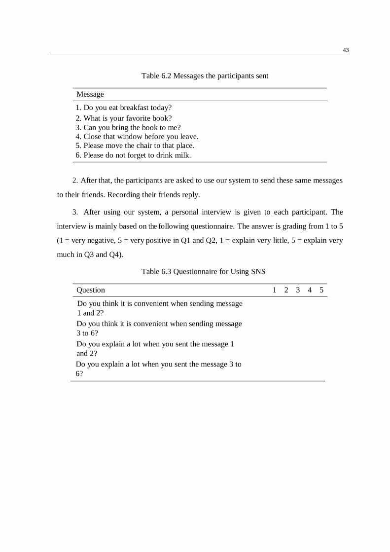
Table 6.2 Messages the participants sent
Message
1. Do you eat breakfast today?
2. What is your favorite book?
3. Can you bring the book to me?
4. Close that window before you leave.
5. Please move the chair to that place.
6. Please do not forget to drink milk.
2. After that, the participants are asked to use our system to send these same messages
to their friends. Recording their friends reply.
3. After using our system, a personal interview is given to each participant. The
interview is mainly based on the following questionnaire. The answer is grading from 1 to 5
(1 = very negative, 5 = very positive in Q1 and Q2, 1 = explain very little, 5 = explain very
much in Q3 and Q4).
Table 6.3 Questionnaire for Using SNS
Question 1 2 3 4 5
Do you think it is convenient when sending message
1 and 2?
Do you think it is convenient when sending message
3 to 6?
Do you explain a lot when you sent the message 1
and 2?
Do you explain a lot when you sent the message 3 to
6?

44
Table 6.4 Questionnaire for Using Our System
Question 1 2 3 4 5
Do you think it is convenient when sending message
1 and 2?
Do you think it is convenient when sending message
3, 4, 5 and 6?
Do you explain a lot when you sent the message 1
and 2?
Do you explain a lot when you sent the message 3 to
6?
6.3 Result
All the participants have completed their experiment and given effective feedback.
After that, we asked them to fill in the questionnaire. We collected 8 questionnaires from 8
participants (5 males and 3 females) totally. Then we did some analysis. There are two types
of messages we asked the participants to send. Message 1 and 2 are the ordinary message
that does not need positional and locational information. Message 3 to 6 are the messages
that may need positional and locational information to understand. Our questionnaire
contains two parts. One is to get the feedback of using SNS message, the other is to get the
feedback of using our system. Then we will make some comparisons between these four
aspects:
• Sending message 1 and 2 using SNS
• Sending message 1 and 2 using our system
• Sending message 3 to 6 using SNS
• Sending message 3 to 6 using our system.
The result of convenience comparison of sending a message is as shows in Figure 6.1:

45
Figure 6.1 Convenience Comparison of Sending Message
The result of sending message 3 to 6 is shown in Figure 6.2:
Figure 6.2 Comparison of the Quantity of Explanation
We can see in Figure 6.1, most people think sending the message 1 and 2 using SNS is
convenient (Point = 5.0) as we predicted. Compare to the SNS, participants think that using
our system to send the message that does not need locational and positional information is

46
less convenient (Point = 4.375). But in the message 3 to 6, most of the participants think that
our system is more convenient (Point = 4.375), using SNS is not convenient (Point = 3.125).
When they are using SNS, they do not need to explain a lot when they send the message 1
and 2 (Point = 1.5), but when they try to send message 3 to 6, they always need to explain a
lot (Point = 4.875). In our system, participants do not need to explain a lot both in message 1
and 2 (Point = 1.5) and message 3 to 6 (Point = 3).
In summary, we can see that when sending a message that does not need the positional
and locational information, SNS is a little convenient than our system, but both SNS message
and our system do not need to explain too much for this kind of message. However, when
sending the message that positional and locational information is important. The SNS message
seems to be not convenient. Our system is easier to use and do not need to explain a lot.

47
Chapter 7
Conclusion
7.1 Summary
In summary, this paper raised some questions about people’s daily communication.
Ordinary SNS is lack of locational and positional information. The traditional sticky note
cannot let people communicate everywhere. Our work is to combine the advantage of the
SNS and sticky notes.
This research builds a spatial note that contains the advantage of SNS and traditional
sticky note. The system can leave a virtual sticky note in the real world and allow people to
read from a distance using their smartphone. First, we used a 360-degree panoramic camera
to shoot the entire room from multiple angles. The resulting photos are then processed and
a 360-degree panoramic model is created from these photos. Then create a three-dimensional
Cartesian coordinate system to record the position of each object in the room. When a user
leaves a note somewhere in the room, the location information for this note is also logged.
After that, the note and its location information will be sent to other users. Other users can
browse all notes and reply via the virtual house model in the smartphone.
By using this system, people can leave and read the notes with locational and positional
information regardless of time and place. The disadvantage of SNS and traditional sticky
notes are abandoned but their advantages are combined in our system.

48
In the evaluation part, we let several users to try our system and design a questionnaire.
After we collect their feedback, we analyze the feedbacks and get some positive results.
7.2 Future Work
In the future, we can improve our system in the following ways. In our tests, it was found
to be very inconvenient to type with fingers, so we can add a voice input method. Now we are
using traditional C/S structure. It is not safe enough for personal privacy. In the future, we
could use a more safe structure.
49
References
[1] Lee K. (2012) Augmented reality in education and training. TechTrends, 56(2): 13-21.
[2] Rosenberg, L. B. (1993, September). Virtual fixtures: Perceptual tools for telerobotic manipulation. In Proceedings of IEEE virtual reality annual international symposium (pp. 76-82). IEEE.
[3] GitHub. (2019). ARToolKit. [online] Available at: https://github.com/artoolkit
[4] Google Developers. (2019). ARCore - Google Developer | ARCore | Google Developers. [online] Available at: https://developers.google.com/ar/
[5] Google Developers. (2019). ARCore overview | ARCore | Google Developers. [online] Available at: https://developers.google.com/ar/discover/
[6] Azuma, R. T. (1997). A survey of augmented reality. Presence: Teleoperators & Virtual Environments, 6(4), 355-385.
[7] Lowe, D. G. (2004). Distinctive image features from scale-invariant keypoints. International journal of computer vision, 60(2), 91-110.
[8] Otero, I. R. (2015). Anatomy of the SIFT Method (Doctoral dissertation, École normale supérieure de Cachan-ENS Cachan).
[9] Nister, D., & Stewenius, H. (2006). Scalable recognition with a vocabulary tree. In 2006 IEEE Computer Society Conference on Computer Vision and Pattern Recognition (CVPR'06) (Vol. 2, pp. 2161-2168). Ieee.
[10] Muja, M., & Lowe, D. G. (2009). Fast approximate nearest neighbors with automatic algorithm configuration. VISAPP (1), 2(331-340), 2
[11] Cheng, J., Leng, C., Wu, J., Cui, H., & Lu, H. (2014). Fast and accurate image matching with cascade hashing for 3d reconstruction. In Proceedings of the IEEE Conference on Computer Vision and Pattern Recognition (pp. 1-8).
[12] Filmic Worlds. (2019). Command-Line Photogrammetry with AliceVision (Tutorial/Guide). [online] Available at: http://filmicworlds.com/blog/command-line-photogrammetry-with-alicevision/.
[13] Hirschmüller, H. (2005, June). Accurate and efficient stereo processing by semi-global matching and mutual information. In null (pp. 807-814). IEEE.
[14]Filmic Worlds. (2019). Command-Line Photogrammetry with AliceVision
(Tutorial/Guide). [online] Available at: http://filmicworlds.com/blog/command-line-
photogrammetry-with-alicevision/.

50
[15]Jancosek, M., & Pajdla, T. (2014). Exploiting visibility information in surface
reconstruction to preserve weakly supported surfaces. International scholarly research
notices, 2014.
[16]Filmic Worlds. (2019). Command-Line Photogrammetry with AliceVision
(Tutorial/Guide). [online] Available at: http://filmicworlds.com/blog/command-line-
photogrammetry-with-alicevision/.
[17] Lévy, B., Petitjean, S., Ray, N., & Maillot, J. (2002, July). Least squares conformal maps for automatic texture atlas generation. In ACM transactions on graphics (TOG) (Vol. 21, No. 3, pp. 362-371). ACM.
[18] Izadi, S., Kim, D., Hilliges, O., Molyneaux, D., Newcombe, R., Kohli, P., ... & Fitzgibbon, A. (2011, October). KinectFusion: real-time 3D reconstruction and interaction using a moving depth camera. In Proceedings of the 24th annual ACM symposium on User interface software and technology (pp. 559-568). ACM.
[19] Geiger, A., Ziegler, J., & Stiller, C. (2011, June). Stereoscan: Dense 3d reconstruction in real-time. In 2011 IEEE Intelligent Vehicles Symposium (IV) (pp. 963-968). Ieee.
[20] Pollefeys, M., Nistér, D., Frahm, J. M., Akbarzadeh, A., Mordohai, P., Clipp, B., ... & Salmi, C. (2008). Detailed real-time urban 3d reconstruction from video. International Journal of Computer Vision, 78(2-3), 143-167.
[21] Qu, P. (2018). Spatial Note System using Virtual-Agent to Enhance Family Connection. ACHI 2019, The Twelfth International Conference on Advances in Computer-Human Interactions, pp.39 to 45.
[22] Tarumi, H., Morishita, K., Nakao, M., & Kambayashi, Y. (1999, July). SpaceTag: An overlaid virtual system and its applications. In Proceedings IEEE International Conference on Multimedia Computing and Systems (Vol. 1, pp. 207-212). IEEE.

51
Appendix A
Evaluation Questionnaire
Questionnaire Ladies/Gentlemen,
Thanks for helping us to complete the Questionnaire. All the information will be only
used in this research. Your information will be greatly valued. Thank you for your
cooperation.
1. How old are you? I am ( ) years old.
2. Your gender is: Male / Female
3. Please fill in the below table:

52


