
SPEAKER SYSTEMS
S112IV/S115IV/S115IVASM10IV/SM12IV/SM15IVS112IVS/S115IVS/S115IVAS/SM12IVSS112IV-OAK/S115IVA-OAKSM10IV-OAK/SM15IV-OAKSUBWOOFER
SW118IV/SW118IVSCROSSOVER NETWORK
PN90
Owner’s ManualMode d’emploiBedienungsanleitungManual de instrucciónes
Thank you for purchasing a YAMAHA product. To obtain
maximum performance from your YAMAHA speaker system
and ensure many years of trouble-free operation, we recommend
that you read this Owner’s Manual thoroughly before use.
ContentsPrecautions ...................................................................... 2
Connecting the Speakers ................................................ 4
Specifications................................................................... 6
Technical Data ...............................................................25Pro Audio & Digital Musical Instrument Division
P.O. Box 3, Hamamatsu, 430-8651, Japan

-2-
Precautions
AVOID EXCESSIVE HEAT, HUMIDITY, DUST AND VI-BRATION
When choosing a location for your speakers, avoid the fol-
lowing:
• Direct sunlight, high temperatures (such as near heat-
ers), or excessively low temperatures.
• High humidity.
• Areas subject to excessive dust accumulation and vibra-
tion.
• Non-level or unstable surfaces.
HOW TO POWER UP YOUR SOUND SYSTEM
To avoid damage to your speakers and other parts of your
system, when you turn on your system, ALWAYS turn the
power amp on last! This will avoid loud, damaging pops
that will annoy your audience, and blow your speakers.
When you power down, the amplifier should ALWAYS be
turned off first to avoid the same problems.
MAKE SURE THE POWER IS OFF BEFORE MAKINGOR REMOVING CONNECTIONS
Always turn the power switches of system components
OFF prior to connecting or disconnecting cables. Failure to
do so may result in damage to speakers as well as to con-
nected equipment.
DISCONNECT CABLES BEFORE MOVING THE SYS-
TEM
To prevent short circuits or breakage of cables, always dis-
connect cables prior to moving system equipment.
MATCH CONNECTOR POLARITY
When using two or more speaker systems, be sure match
the polarity (+/–) of the speaker system connectors to those
at the amplifier. If the polarities do not match, the sounds
produced by the speakers will interfere with each other,
making it impossible to achieve a well-balanced sound
field.
KEEP THIS OWNER’S MANUAL IN A SAFE PLACEFOR FUTURE REFERENCE
To protect your speakers
When choosing a power amplifier to use with your
speakers, make sure that its power output matches the
speakers’ power capacity (refer to the Specifications on
page 6). Even if the amplifier’s power output is lower
than the speakers’ PGM (program) power capacity, the
speakers may be damaged when clipping of a high input
signal occurs.
The following may cause damage to speakers:
• Feedback caused when using a microphone.
• Continuous high sound pressure level produced by
electronic instruments.
• Continuous high-power output distorted signals.
• Popping noises caused by turning on equipment, or
by connecting or disconnecting system components
while the amplifier is turned on.
Poly Switch
All full-range loudspeakers are fitted with a self-reset-
ting poly switch that protects the high-frequency driver
from damage caused by excessive power.
If a loudspeaker cabinet loses high-frequency output,
immediately remove power from the unit and wait for
two to three minutes. They should allow the poly switch
to reset. Re-apply power and check the performance of
the high-frequency driver before continuing with the
power reduced to a level that does not cause the poly
switch to interrupt the signal.
On the SW118IV/SW118IVS sub woofer, the Poly
Switch protects the woofer and a similar routine should
be followed if its output is lost.

-3-
This product, when used in combination
with amplification and/or additional
loudspeakers, may be capable of produc-
ing sound levels that could cause perma-
nent hearing loss.
DO NOT operate at high volume levels
or at a level that is uncomfortable. If you
experience any discomfort or ringing in
the ears, or suspect an hearing loss, you
should consult an audiologist.
CAUTION!For the eight models, S112IV, S112IVS, S115IV, S115IVS,
SM10IV, SM12IV, SM12IVS, and SM15IV, use the TS-30,
TS-40, TS-80, or TS-90 speaker stand by Ultimate Support
System, Inc. sold separately.
When using speaker stands, observe the following precau-
tions to prevent the speaker stands from falling over or the
speaker system being dropped.
• Use the speaker stands with their legs fully opened.
• Do not place more than one speaker on the same speaker
stand.
• Tighten fastening screws securely.
• Remove the speakers from the stands before moving the
stands or adjusting their height.
• Implement measures to prevent the speaker stands from
falling over.
• Use the TS-30, TS-40 at no higher than 130 cm for the
S112IV, S112IVS, SM10IV, SM12IV or SM12IVS and at
no higher than 120 cm for the S115IV, SM15IV and
S115IVS.
• Use the TS-80 and TS-90 at no higher than 140 cm for
all speaker models.
• The top tube of the TS-30 and TS-40 speaker stands has
a diameter of 1-1/2", but is tapered to 1-3/8" at the top to
fit in the mounting holes on the eight models named. If
you should remove the top tube from a stand, be sure to
insert it with the narrow end up when reassembling.
The SW118IV, SW118IVS subwoofer has a metal socket
to allow mounting of a satellite speaker. Do not use a pole
longer than 56". Use a pole with an outer diameter of 1-3/
8".
SPEAKER HANDLES
The handles on your speakers are for transportation. They
are not designed for suspension or hanging. Only the “A”
versions of these speakers are designed for suspension.
Please consult a qualified engineer for proper hanging
techniques.
Fly-Ware
Model S115IVA, S115IVAS, S115IVA-OAK
These speakers are supplied with Fly-Ware rigging hard-
ware installed. The following notes explain how to prepare
these speakers for suspension.
IMPORTANT! This material does not explain how tosuspend speakers.
To properly suspend any speaker, a knowledge of struc-
tural engineering and structural rigging is REQUIRED.
Suspending loudspeakers requires special tools and tech-
niques. Do not attempt to suspend any speaker system un-
less you have received specific training to do so.
The improper installation of flying speakers can result in
bodily injury or death.
Always consult a licensed engineer to verify the design of
any suspended system. In addition, please follow these
safety steps:
• Use only hardware specifically designed for rigging ap-
plications.
• Always use an independent safety suspension system as
a backup.
• Get professional help.
To prepare these speakers for suspension:
1. Remove the flathead screws from the top of the speaker.
Note: The 3/8" flathead screws use a 7/32" hex wrench.
Take care not to remove both screws from each corner,
as the internal bracket will fall inside the loudspeaker.
2. Apply a drop of thread locking adhesive to the end of
the threads of the eyebolts.
Note: Please use the supplied eyebolts found in the car-
rying handle of the speaker. If you use any part other
than that supplied, be sure it is Load Rated and know
that it will be de-rated if not suspended so that the pull
direction is in-line.
3. Install the eyebolts into the holes on top of the speaker
and finger-tighten.
4. Securely tighten the eyebolts. Hand tighten +1/2 turn.
5. Inspect the other six (6) flathead screws, making sure
they are tightened down.
-4-
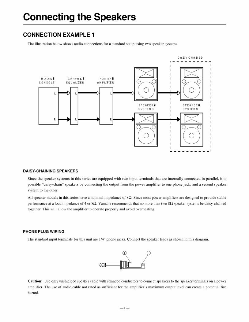
Connecting the Speakers
CONNECTION EXAMPLE 1The illustration below shows audio connections for a standard setup using two speaker systems.
MIXINGCONSOLE
GRAPHICEQUALIZER
SPEAKERSYSTEMS
L
R
L
R
SPEAKERSYSTEMS
DAISY-CHAINED
POWERAMPLIFIER
L
R
DAISY-CHAINING SPEAKERS
Since the speaker systems in this series are equipped with two input terminals that are internally connected in parallel, it is
possible “daisy-chain” speakers by connecting the output from the power amplifier to one phone jack, and a second speaker
system to the other.
All speaker models in this series have a nominal impedance of 8Ω. Since most power amplifiers are designed to provide stable
performance at a load impedance of 4 or 8Ω, Yamaha recommends that no more than two 8Ω speaker systems be daisy-chained
together. This will allow the amplifier to operate properly and avoid overheating.
PHONE PLUG WIRING
The standard input terminals for this unit are 1/4" phone jacks. Connect the speaker leads as shown in this diagram.
Caution: Use only unshielded speaker cable with stranded conductors to connect speakers to the speaker terminals on a power
amplifier. The use of audio cable not rated as sufficient for the amplifier’s maximum output level can create a potential fire
hazard.

-5-
CONNECTION EXAMPLE 2This example shows audio connections for a system using SW118IV or SW118IVS Subwoofers and a PN90 Crossover Network.
SW118IVor
SW118IVS
MIXINGCONSOLE
TWO-CHANNELGRAPHICEQUALIZER
LEFT
INPUTS
RIGHT
PN90
LEFT
HIGH
RIGHT
INPUT
TO POWERAMP INPUTS
LEFT
RIGHT
LOW INPUT
TWO-CHANNELPOWER AMPLIFIER
TWO-CHANNELPOWER AMPLIFIER
OUTPUT
OUTPUT
SPEAKERSYSTEM
SW118IVor
SW118IVS
SPEAKERSYSTEM
L
R
L
R
L
R
L
R
L
R
L
R
• Do not connect the PN90 between the power amplifiers and the SW118IV, SW118IVS subwoofers, as doing so will damage
the equipment.
• Although the PN90 has a standard load impedance of 15 kΩ, it can be used with loads between 7.5 and 30 kΩ, allowing use
with most power amplifiers.
• Since the LOW signal polarity is inverted at the crossover point between the LOW and HIGH signals, be sure to reverse the
polarity when connecting the SW118IV, SW118IVS input jacks to the power amplifier output jacks.
This polarity correction must not be made by reversing the polarity of the connections between the PN90 and the power
amplifiers, as doing so will damage the equipment. Please reverse the polarity between the power amplifiers and the
SW118IVs, SW118IVSs.
• The PN90 uses unbalanced connectors. Use shielded audio cable with high-quality phone plugs to connect the PN90.
The balance between the LOW and HIGH signal levels may be adjusted using the power amplifier volume controls. A good
starting point is generally achieved for typical sound sources by raising the LOW signal level about 8 dB higher than that of the
HIGH signal.

-6-
W
H
D216
63.5
φ6.2
W
H
D
120˚
30˚
W
H
D
75˚ 105˚
S112IV, S112IVS,
S112IV-OAK,
S115IV, S115IVS,
S115IVA, S115IVAS,
S115IVA-OAK
SM10IV, SM10IV-OAK,
SM12IV, SM12IVS,
SM15IV, SM15IV-OAK
Model SW118IV/SW118IVS
Enclosure Bass reflex type
Speaker Unit 18" cone
Frequency Response 30 Hz to 2 kHz
Power Capacity NOISE* 250 W
PGM 500 W
MAX 1000 W
Nominal Impedance 8ΩSensitivity 96 dB SPL (1W, 1m)
Recommended Crossover Frequency 90 Hz, 12 dB/octave
Input Connectors 1/4" phone jack x 2 (parallel input)
Dimensions (W x H x D) 542 x 654 x 791 mm
Weight 32.4 kg
W
H
D
Model SM10IV/SM10IV-OAKS112IV/S112IVS/SM12IV/ S115IV/S115IVS/S115IVA/S115IVAS/
SM12IVS/S112IV-OAK S115IVA-OAK/SM15IV/SM15IV-OAK
Enclosure Bass reflex type
Speaker Unit LF 10" cone 12" cone 15" cone
HF 1" driver 2" driver
Frequency Response 70 Hz to 20 kHz 60 Hz to 16 kHz 55 Hz to 16 kHz
Power Capacity NOISE* 100 W 150 W 250 W
PGM 200 W 300 W 500 W
MAX 400 W 600 W 1000 W
Nominal Impedance 8ΩSensitivity 95 dB SPL (1W, 1m) 97 dB SPL (1W, 1m) 99 dB SPL (1W, 1m)
Nominal Dispersion Horizontal 60˚ 90˚
Vertical 40˚
Crossover Frequency 1.8 kHz 2 kHz 1.7 kHz
Input Connectors 1/4" phone jack x 2 (parallel input)
Dimensions (W x H x D) SM10IV: 560 x 339 x 277 mm S112IV/S112IVS: 400 x 638 x 318 mm S115IV/S115IVS/S115IVA/S115IVAS: 475 x 712 x 362 mm
SM10IV-OAK: SM12IV/SM12IVS: 643 x 402 x 344 mm SM15IV: 720 x 485 x 345 mm
526 x 316 x 261 mm S112IV-OAK: 400 x 620 x 318 mm S115IV-OAK: 479 x 695 x 360 mm
SM15IV-OAK: 695 x 479 x 340 mm
Weight SM10IV: 12.2 kg S112IV/S112IVS: 19.3 kg, S115IV/S115IVS/S115IVA/S115IVAS: 27.5 kg,
SM10IV-OAK: 10.5 kg SM12IV/SM12IVS: 19.5 kg, SM15IV: 26 kg
S112IV-OAK: 18 kg S115IV-OAK: 27.5 kg, SM15IV-OAK: 26 kg
Specifications
Model PN90
Crossover Frequency 90 Hz, 12 dB/octave (at 15 kΩ load)
Recommended Load Impedance 15 kΩInsertion loss 3 dB
Input Connectors 1/4" phone jack x 2
Output Connectors 1/4" phone jack x 4
Dimensions (W x H x D) 227 x 38 x 76 mm
Weight 0.6 kg
Unit: mm
*: EIA RS-426
Specifications subject to change without notice
SW118IV,
SW118IVS
PN90

Fra
nça
is
Enceintes
S112IV/S115IV/S115IVASM10IV/SM12IV/SM15IVS112IVS/S115IVS/S115IVAS/SM12IVSS112IV-OAK/S115IVA-OAKSM10IV-OAK/SM15IV-OAKCaisson de grave
SW118IV/SW118IVSCircuit diviseur de fréquence
PN90
Mode d’emploi
Nous vous remercions d’avoir acheté ce produit YAMAHA.
Pour obtenir les performances maximales de vos enceintes
YAMAHA et garantir de nombreuses années d’utilisation sans
problème, nous vous recommandons de lire attentivement tout
ce mode d’emploi avant d’utiliser les enceintes.
Table des matièresPrécautions ...................................................................... 8
Raccordement des enceintes ........................................ 10
Fiche technique .............................................................12
Données techniques ......................................................25
-8-
Précautions
Eviter toute chaleur, humidité, poussière et vibra-tions excessives.
Lors de la sélection de l’emplacement d’installation des
enceintes, éviter les endroits suivants :
• En plein soleil, soumis à de fortes températures (par
exemple près d’un appareil de chauffage), ou à des
températures excessivement basses.
• Forte humidité.
• Endroits soumis à une accumulation de poussière et des
vibrations excessives.
• Surfaces inclinées ou instables.
Alimentation des enceintes
Pour éviter tout dommage des enceintes et des autres
éléments de la chaîne, lors de la mise sous tension du
système, TOUJOURS allumer l’ampli de puissance en
dernier. Ceci évitera les brusques émissions de son puis-
sant qui gêneront l’auditoire et feront sauter les enceintes.
Lors de la mise hors tension de la chaîne, TOUJOURS
éteindre l’amplificateur en dernier pour éviter les mêmes
problèmes.
Vérifier que la chaîne est hors tension avant toutbranchement ou débranchement
Toujours couper (OFF) les interrupteurs d’alimentation
des éléments de la chaîne avant de brancher ou de
débrancher les câbles. Sinon, l’on risque d’endommager
les enceintes ainsi que l’appareil auquel elles sont
raccordées.
Débrancher les câbles avant de déplacer la chaîne
Pour éviter tout risque de court-circuit ou de rupture des
câbles, toujours débrancher les câbles avant de déplacer la
chaîne.
Respecter les polarités des connecteurs
Lorsqu’on utilise deux paires d’enceintes ou plus, bien
veiller à faire correspondre les polarités (+/-) des
connecteurs d’enceinte à celles de l’amplificateur. Si les
polarités ne correspondent pas, les sons restitués par les
enceintes interféreront entre eux, et il ne sera pas possible
d’obtenir un équilibre satisfaisant du champ sonore.
Conserver ce mode d’emploi en lieu sûr de façon àpouvoir s’y référer.
Protection des enceintesLors de la sélection de l’amplificateur à utiliser avec lesenceintes, vérifier que sa puissance de sortie correspondà la capacité de puissance des enceintes (voir la fichetechnique de la page 12). Si la puissance de sortie del’amplificateur est inférieure à la capacité de puissancePGM (programme) des enceintes, les enceintes risquentd’être endommagées lors de l’écrêtage d’un signald’entrée élevé.
Les phénomènes suivants risquent d’endommager lesenceintes :
• Effet Larsen provoqué lors de l’utilisation d’un mi-crophone.
• Haut niveau de pression sonore continu engendré pardes instruments électroniques.
• Signaux déformés par une puissance de sortie élevéecontinue.
• Brusques émissions de son puissant provoquées parla mise sous tens ion des appare i l s ou ledébranchement des éléments de la chaîne lorsquel’amplificateur est allumé.
PolycommutateurToutes les enceintes à plage intégrale sont équipées
d’un polycommutateur à réenclenchement automatique
qui protège le driver haute fréquence contre les
dommages résultant d’un excès de puissance.
Si le coffret du haut-parleur cesse de restituer les hautes
fréquences, le mettre immédiatement hors tension et
attendre deux ou trois minutes. Ceci devrait permettre
au polycommutateur de se réenclencher. Remettre
l’enceinte sous tension et vérifier les performances du
driver haute fréquence avant de continuer, en réduisant
la puissance à un niveau tel que le polycommutateur ne
coupe plus le signal.
Sur le caisson de grave SW118IV/SW118IVS, le
polycommutateur protège le boomer, et il faudra donc
procéder de même si la sortie est interrompue.

-9-
Fra
nça
is
Lorsqu’il est combiné à un amplificateur
et/ou des haut-parleurs supplémentaires,
cet appareil risque d’engendrer des
niveaux sonores capables de provoquer
une perte permanente d’audition.
NE PAS faire fonctionner à des niveaux de
volume élevés ou inconfortables. Si l’on
éprouve une gêne, qu’on ressent un
bourdonnement dans les oreilles ou qu’on
soupçonne une perte d’audition, consulter
un spécialiste de l’ouïe.
ATTENTION !Pour les huit modèles, S112IV, S112IVS, S115IV, S115IVS,SM10IV, SM12IV, SM12IVS et SM15IV, utiliser des soclesd’enceinte TS-30, TS-40, TS-80 ou TS-90 de Ultimate Sup-port System, Inc. vendus séparément.
A l’emploi de socles d’enceinte, observer les précautionssuivantes pour éviter le renversement du socle ou la chute del’enceinte.
• Utiliser les socles avec les jambes entièrement écartées.
• Ne pas placer plus d’une enceinte sur un socle d’enceinte.
• Serrer fermement les vis de fixation.
• Retirer l’enceinte du socle avant de déplacer un socle ou derégler sa hauteur.
• Prendre les mesures nécessaires pour éviter lerenversement des socles d’enceinte.
• Utiliser le TS-30, TS-40 à une hauteur maximale de 130 cmpour les S112IV, S112IVS, SM10IV, SM12IV ou SM12IVSet à une hauteur maximale de 120 cm pour les S115IV,SM15IV et S115IVS.
• Utiliser le TS-80 et le TS-90 à une hauteur maximale de140 cm pour tous les modèles d’enceinte.
• Le tube supérieur des socles d’enceinte TS-30 et TS-40possède un diamètre de 1-1/2 po., mais il a été taillé enbiseau à 1-3/8 po. à son extrémité supérieure de façon àpouvoir rentrer dans les orifices de montage des huitmodèles ci-dessus. Si l’on retire le tube supérieur d’unsocle, bien l’insérer avec son extrémité étroite vers le hautlors du remontage.
Le caisson de grave SW118IV, SW118IVS possède une prisemétallique en vue de la fixation d’un haut-parleur satellite. Nepas utiliser de support de plus de 56 po. de long. Utiliser untube ayant un diamètre extérieur de 1-3/8”.
Poignées d’enceinte
Les poignées qui sont fixées sur les enceintes sont conçues àdes fins de transport. Elles ne sont pas conçues pour
suspendre ou accrocher les enceintes. Seules les versions “A”de ces enceintes sont conçues pour être accrochées. Pour laméthode de suspension, consulter un ingénieur qualifié.
Matériel de fixation Fly-WareModèle S115IVA, S115IVAS, S115IV-OAK
Les enceintes sont livrées avec un dispositif de haubanageFly-Ware déjà installé. Nous expliquons ci-dessous commentpréparer ces enceintes pour la suspension.
IMPORTANT ! Ce manuel n’explique pas commentaccrocher les enceintes.
Pour accrocher une enceinte correctement, il estNECESSAIRE d’avoir un minimum de connaissances enmatière de génie et de haubanage structurels. La suspensiondes enceintes exige des outils et des techniques spéciaux. Nepas tenter d’accrocher des enceintes si l’on n’a pas suivi uneformation spéciale.
Une installation incorrecte d’enceintes volantes peut entraînerdes blessures graves ou mortelles.
Toujours consulter un ingénieur agréé pour vérifier la concep-tion de tout système de suspension. En outre, observer lesmesures de précaution suivantes :
• Utiliser exclusivement le matériel de fixation conçu pourdes applications de haubanage.
• A des fins de sécurité, toujours utiliser un système de sus-pension de secours indépendant.
• Se faire aider par un professionnel.
Préparatifs de suspension des enceintes :1. Retirer les vis à tête plate du dessus de l’enceinte.
Remarque: Les vis à tête plate de 3/8 po. nécessitent uneclé hexagonale de 7/32 po. Faire attention de ne pas retirerles deux vis de chaque coin, car l’étrier interne tomberait àl’intérieur de l’enceinte.
2. Mettre une goutte d’adhésif de filetage à l’extrémité desfiletages de boulon à œillet.
Remarque: Utiliser les boulons à œillet qui ont été prévusdans la poignée de transport de l’enceinte. Si l’on utilisedes pièces autres que celles qui sont fournies, veiller à cequ’elles respectent la charge nominale, et bien savoir quela charge nominale sera réduite si l’enceinte est suspenduede façon que le sens de la traction n’est pas aligné.
3. Insérer les boulons à œillet dans les orifices sur le dessusde l’enceinte et les serrer à la main.
4. Fixer les boulons à œillet à fond. Serrer à la main d’undemi-tour vers la droite.
5. Inspecter les six (6) autres vis à tête plate pour s’assurerqu’elles sont bien vissées à fond.
-10-
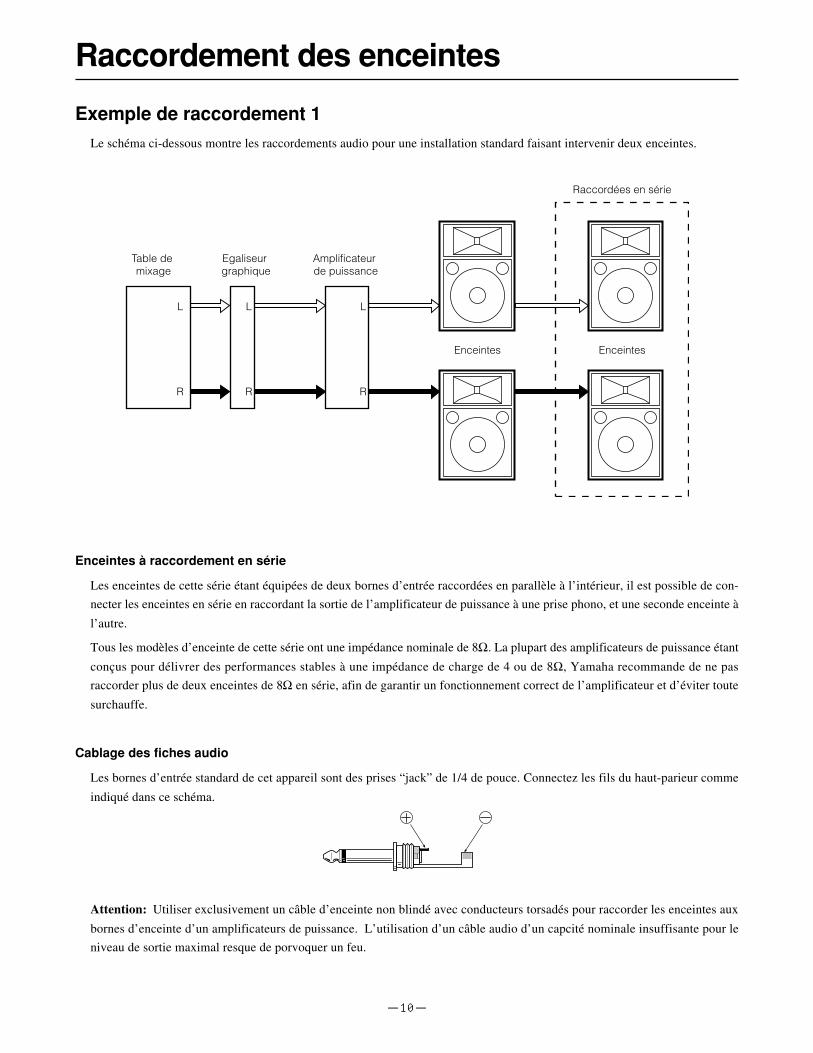
Raccordement des enceintes
Exemple de raccordement 1Le schéma ci-dessous montre les raccordements audio pour une installation standard faisant intervenir deux enceintes.
Table de mixage
Egaliseur graphique
Enceintes
L
R
L
R
Enceintes
Raccordées en série
Amplificateur de puissance
L
R
Enceintes à raccordement en série
Les enceintes de cette série étant équipées de deux bornes d’entrée raccordées en parallèle à l’intérieur, il est possible de con-
necter les enceintes en série en raccordant la sortie de l’amplificateur de puissance à une prise phono, et une seconde enceinte à
l’autre.
Tous les modèles d’enceinte de cette série ont une impédance nominale de 8Ω. La plupart des amplificateurs de puissance étant
conçus pour délivrer des performances stables à une impédance de charge de 4 ou de 8Ω, Yamaha recommande de ne pas
raccorder plus de deux enceintes de 8Ω en série, afin de garantir un fonctionnement correct de l’amplificateur et d’éviter toute
surchauffe.
Cablage des fiches audio
Les bornes d’entrée standard de cet appareil sont des prises “jack” de 1/4 de pouce. Connectez les fils du haut-parieur comme
indiqué dans ce schéma.
Attention: Utiliser exclusivement un câble d’enceinte non blindé avec conducteurs torsadés pour raccorder les enceintes aux
bornes d’enceinte d’un amplificateurs de puissance. L’utilisation d’un câble audio d’un capcité nominale insuffisante pour le
niveau de sortie maximal resque de porvoquer un feu.

-11-
Fra
nça
is
Exemple de raccordement 2Le schéma ci-dessous montre les raccordements audio pour un système faisant intervenir des caissons de grave SW118IV ou
SW118IVS et un circuit diviseur de fréquence PN90.
Table de mixage
Egaliseur graphique à deux voies
Gauche
Entrées
Droite
PN90
Gauche
HIGH (élevé)
Droite
Entrée
Vers les entrées d’ampli de puissance
Gauche
Droite
LOW (faible) Entrée
Amplificateur de puissance à deux voies
Amplificateur de puissance à deux voies
Sortie
Sortie
Enceinte
SW118IVou
SW118IVS
SW118IVou
SW118IVS
Enceinte
L
R
L
R
L
R
L
R
L
R
L
R
• Ne pas raccorder le PN90 entre les amplificateurs de puissance et les caissons de grave SW118IV, SW118IVS, car cela
endommagerait les appareils.
• Bien que le PN90 ait une impédance de charge standard de 15 kΩ, il peut fonctionner avec des charges comprises entre 7,5 et
30 kΩ, ce qui permet d’utiliser pratiquement n’importe quel amplificateur de puissance.
• La polarité du signal LOW étant inversée au point de croisement entre les signaux LOW et HIGH, bien inverser la polarité
lorsqu’on raccorde les prises d’entrée du SW118IV, SW118IVS aux prises de sortie de l’amplificateur de puissance.
Ne pas effectuer cette correction de polarité en inversant la polarité des raccordements entre le PN90 et les amplificateurs de
puissance, car cela endommagerait les appareils. Inverser la polarité entre les amplificateurs de puissance et le SW118IV,
SW118IVS.
• Le PN90 utilise des connecteurs asymétriques. Utiliser un câble audio blindé avec fiches phono de haute qualité pour le
raccordement du PN90.
La balance entre le niveau du signal LOW et celui du signal HIGH se règle avec la commande de volume des amplificateurs de
puissance. Pour les sources sonores classiques, il est généralement conseillé de commencer par régler le niveau du signal LOW
à environ 8 dB de plus que celui du signal HIGH.

-12-
W
H
D216
63.5
φ6.2
W
H
D
120˚
30˚
W
H
D
75˚ 105˚
S112IV, S112IVS,
S112IV-OAK,
S115IV, S115IVS,
S115IVA, S115IVAS,
S115IVA-OAK
SM10IV, SM10IV-OAK,
SM12IV, SM12IVS,
SM15IV, SM15IV-OAK
Modèle SW118IV/SW118IVS
Coffret Type bass reflex
Haut-parleur Cône de 18 po.
Réponse en fréquence 30 Hz to 2 kHz
Capacité de BRUIT* 250 W
puissance PGM 500 W
MAX 1000 W
Impédance nominale 8ΩSensibilité 96 SPL (1 W, 1 m)
Fréquence de recouvrement 90 Hz, 12 dB/octave
recommandée
Connecteurs d’entrée Prise phono 1/4 po. x 2 (entrée parallèle)
Dimensions (L x H x P) 542 x 654 x 791 mm
Poids 32.4 kg
W
H
D
Modèle SM10IV/SM10IV-OAKS112IV/S112IVS/SM12IV/ S115IV/S115IVS/S115IVA/S115IVAS/
SM12IVS/S112IV-OAK S115IVA-OAK/SM15IV/SM15IV-OAK
Coffret Type bass reflex
Haut-parleur LF Cône de 10 po. Cône de 12 po. Cône de 15 po.
HF Driver de 1 po. Driver de 2 po.
Réponse en fréquence 70 Hz to 20 kHz 60 Hz to 16 kHz 55 Hz to 16 kHz
Capacité de BRUIT* 100 W 150 W 250 W
puissance PGM 200 W 300 W 500 W
MAX 400 W 600 W 1000 W
Impédance nominale 8ΩSensibilité 95 dB SPL (1 W, 1 m) 97 dB SPL (1 W, 1 m) 99 dB SPL (1 W, 1 m)
Dispersion nominale Horizontale 60˚ 90˚
Verticale 40˚
Fréquence de recouvrement 1.8 kHz 2 kHz 1.7 kHz
Connecteurs d’entrée Prise phono 1/4 po. x 2 (entrée parallèle)
Dimensions (L x H x P) SM10IV: 560 x 339 x 277 mm S112IV/S112IVS: 400 x 638 x 318 mm S115IV/S115IVS/S115IVA/S115IVAS: 475 x 712 x 362 mm
SM10IV-OAK: SM12IV/SM12IVS: 643 x 402 x 344 mm SM15IV: 720 x 485 x 345 mm
526 x 316 x 261 mm S112IV-OAK: 400 x 620 x 318 mm S115IV-OAK: 479 x 695 x 360 mm
SM15IV-OAK: 695 x 479 x 340 mm
Poids SM10IV: 12.2 kg S112IV/S112IVS: 19.3 kg, S115IV/S115IVS/S115IVA/S115IVAS: 27.5 kg,
SM10IV-OAK: 10.5 kg SM12IV/SM12IVS: 19.5 kg, SM15IV: 26 kg,
S112IV-OAK: 18 kg S115IV-OAK: 27.5 kg, SM15IV-OAK: 26 kg
Fiche technique
Modèle PN90
Fréquence de recouvrement 90 Hz, 12 dB/octave
(pour une charge de 15 kohms)
Impédance de charge recommandée 15 kΩPerte d’insertion 3 dB
Connecteurs d’entrée Prise phono 1/4 po. x 2
Connecteurs de sortie Prise phono 1/4 po. x 4
Dimensions (L x H x P) 227 x 38 x 76 mm
Poids 0.6 kg
Unité : mm
*: EIA RS-426
Spécifications sujettes à modification sans préavis.
SW118IV,
SW118IVS
PN90

Deu
tsch
LAUTSPRECHERSYSTEM
S112IV/S115IV/S115IVASM10IV/SM12IV/SM15IVS112IVS/S115IVS/S115IVAS/SM12IVSS112IV-OAK/S115IVA-OAKSM10IV-OAK/SM15IV-OAKSUBWOOFER
SW118IV/SW118IVSFREQUENZWEICHE
PN90
Bedienungsanleitung
Wir beglückwünschen Sie zum Kauf dieses YAMAHA-Geräts.
Lesen Sie bitte vor der Inbetriebnahme diese Anleitung
sorgfältig durch, damit Ihr YAMAHA-Lautsprecherssystems
seine volle Leistung entfaltet und ein störungsfreier Betrieb
gewährleistet ist.
InhaltZur besonderen Beachtung ...........................................14
Anschluß derLautsprecher .............................................16
Technische Daten ..........................................................18
Kennlinien ......................................................................25

-14-
Zur besonderen Beachtung
Vor Hitze, Feuchtigkeit, Staub und Vibrationenschützen
Stellen Sie Ihre Lautsprecher nicht an folgende Plätze:
• Plätze, die direktem Sonnenlicht, hohen Temperaturen
(Nähe von Heizungen usw.) oder niedrigen
Temperaturen ausgesetzt sind.
• Plätze, die hoher Feuchtigkeit ausgesetzt sind.
• Plätze, die Staub und Vibrationen ausgesetzt sind.
• Schräge oder unstabile Unterlagen.
Beim Einschalten bitte beachten
Schalten Sie stets den Verstärker der Anlage als letztes
ein. Sie verhindern dadurch Einschaltstromstöße, die zu
unangenehmen, lauten Störgeräuschen und zu
Beschädigungen des Lautsprechers oder anderen
Komponenten Ihrer Anlage führen können. Aus dem
gleichen Grund sollte am Ende des Betriebs der
Verstärker stets als letztes ausgeschaltet werden.
Vor dem Anschließen und Abtrennen von Kabelnstets die Stromversorgung ausschalten
Schalten Sie die Netzschalter der Geräte stets aus, bevor
Sie Kabel anschließen oder abtrennen. Ansonsten können
die Lautsprecher oder Geräte Ihrer Anlage beschädigt
werden.
Vor dem Transport der Anlage die Kabel abtrennen
Trennen Sie die Kabel stets ab, bevor Sie Ihre Anlage
transportieren. Dadurch verhindern Sie Kurzschlüsse und
Beschädigungen der Kabel.
Auf richtige Polarität achten
Wenn Sie zwei oder mehr Lautsprecher verwenden,
schließen Sie sie mit richtiger +/- Polarität an den
Verstärker an, damit sie gleichphasig arbeiten. Ansonsten
kommt es zu einem unausgewogenen Klangbild.
Heben Sie die Anleitung zum späterenNachschlagen gut auf
Schutz der Lautsprecher
Betreiben Sie Ihre Lautsprecher nur mit einem
Verstärker, dessen Ausgangsleistung die “Programm”-
Belastbarkeit der Lautsprecher (siehe Technische Daten
auf Seite 18) nicht überschreitet. Beachten Sie auch, daß
es selbst bei geringer Verstärker-Ausgangsleistung durch
Clippen der Hochtonsignale sowie in den folgenden
Fällen zu einer Beschädigung der Lautsprecher kommen
kann.
Durch folgendes können die Lautsprecher beschädigt
werden:
• Akustische Rückkopplung über ein Mikrofon.
• Anhaltende hochpeglige Signale hoher Frequenz von
elektronischen Musikinstrumenten.
• Anhaltende verzerrte Signale hoher Leistung.
• Poppgeräusche, die entstehen, wenn bei
eingeschaltetem Verstärker ein Gerät der Anlage
eingeschaltet, angeschlossen oder abgetrennt wird.
Poly-Schalter
Die Breitbandlautsprecher sind mit einem Poly-
Schalter ausgestattet, der das Signal im Falle einer
Höhenübersteuerung unterbricht und damit
Beschädigungen des Hochtöners vorbeugt.
Wenn über einen Lautsprecher keine Höhen mehr zu
hören sind, brechen Sie sofort den Betrieb ab, und
warten Sie etwa 3 Minuten, bis sich der Poly-Schalter
automatisch zurückgesetzt hat. Nachdem Sie die
Ursache der Höhenübersteuerung beseitigt haben,
können Sie den Betrieb fortsetzen.
Auch der Subwoofer SW118IV/SW118IVS ist mit
einem Poly-Schalter ausgestattet. Die Vorgehensweise
beim Ansprechen dieses Schalters ist dieselbe.

-15-
Dieses Produkt kann in Kombination miteinem Verstärker undZusatzlautsprechern Hörschädenverursachen.
Betreiben Sie die Lautsprecher niemalsmit einem Lautstärkepegel, der alsunangenehm empfunden wird. Wenn Sieein unangenehmes, dumpfes Gefühl inden Ohren verspüren oder IhrHörvermögen nachläßt, wenden Sie sichan einen Arzt.
VORSICHT!Verwenden Sie für die acht Modelle S112IV, S112IVS,S115IV, S115IVS, SM10IV, SM12IV, SM12IVS und SM15IVden von der Ultimate Support System, Inc. als Sonderzubehörerhältlichen Lautsprecherständer TS-30, TS-40, TS-80 oderTS-90.
Beachten Sie dabei die folgenden Sicherheitsvorkehrungen,damit der Ständer nicht umkippt und der Lautsprecher nichtherunterfällt.
• Klappen Sie die Beine der Ständer ganz heraus.
• Stellen Sie auf jeden Ständer nur einen Lautsprecher.
• Ziehen Sie die Befestigungsschrauben gut fest.
• Nehmen Sie die Lautsprecher herunter, bevor Sie dieStänder bewegen oder die Höhe einstellen.
• Sichern Sie die Lautsprecher so, daß sie nichtherunterfallen können.
• Bei Verwendung des S112IV, S112IVS, SM10IV, SM12IVoder SM12IVS darf der TS-30, TS-40 nicht höher als 130cm und bei Verwendung des S115IV, SM15IV undS115IVS nicht höher als 120 cm eingestellt werden.
• Die Ständer TS-80 und TS-90 dürfen unabhängig von denLautsprechermodellen nicht höher als 140 cm eingestelltwerden.
• Das obere Rohr des Ständers TS-30 und TS-40 besitzteinen Durchmesser von 1-1/2". Im oberen Bereich läuft eskonisch auf 1-3/8" zu und stimmt mit denMontagebohrungen der obigen acht Modelle überein.Wenn Sie das obere Rohr vom Ständer abgenommenhaben, setzen Sie es mit dem engeren Ende nach obenwieder ein.
Der Subwoofer SW118IV, SW118IVS besitzt einenMetallsockel für die Montage von Satellitenlautsprechern.Verwenden Sie keinen Arm, der länger als 56" ist. Bitteverwenden Sie ein Rohr mit einem Außendurchmesser von1-3/8”.
Lautsprechergriffe
Die Lautsprechergriffe sind nur für den Transport bestimmt.Sie dienen nicht zum Befestigen und Aufhängen der
Lautsprecher. Nur Lautsprecher der Version “A” sind zumAufhängen ausgelegt. Zum Aufhängen der Lautsprecherwenden Sie sich an einen Fachmann.
Fly-Ware (Modell S115IVA, S115IVAS, S115IVA-OAK)
Diese Lautsprecher werden mit Fly-Ware-Abspannmaterialgeliefert. Im folgenden werden die zum Aufhängen derLautsprecher erforderlichen Vorbereitungen behandelt.
Wichtiger Hinweis! Der folgende Abschnitt behandeltnicht das Verfahren zum Aufhängen der Lautsprecher.
Zur sicheren Aufhängung der Lautsprecher sindbautechnische Kenntnisse unbedingt erforderlich. Es werdenSpezialwerkzeuge und spezielle Techniken benötigt.Hängen Sie Lautsprecher nur auf, wenn Sie sich auf einerSpezialschulung die erforderlichen Fachkenntnisseangeeignet haben.
Bei unsachgemäßer Aufhängung der Lautsprecher kann eszu Verletzungen von Personen und Todesfällen kommen.
Jedes Aufhängungssystem muß von einem qualifiziertenFachmann abgenommen werden. Beachten Sie stets diefolgenden grundsätzlichen Sicherheitshinweise:
• Verwenden Sie nur Teile, die speziell zum Aufhängenvon Lautsprechern ausgelegt sind.
• Sehen Sie ein getrenntes Notsicherungssystem vor.
• Konsultieren Sie einen Fachmann.
Vorbereitung der Lautsprecheraufhängung:
1. Entfernen Sie Flachkopfschrauben an der Oberseite desLautsprechers.
Hinweis: Für die 3/8"-Flachkopfschrauben wird ein 7/32"-Steckschlüssel benötigt. Entfernen Sie nicht diebeiden Schrauben an den Ecken, da sonst die interneHalterung in die Lautsprecher fällt.
2. Tropfen Sie etwas Gewindeversiegeler auf dasGewindeende der Ringschrauben.
Hinweis: Verwenden Sie die Ringschrauben amTragegriff des Lautsprechers. Wenn Sie andereSchrauben verwenden, vergewissern Sie sich, daß ihredie Belastbarkeit ausreicht. Beachten Sie auch, daß beischräger Zugspannung die Belastung für die Schraubengrößer ist
3. Drehen Sie die Bolzen per Hand vollständig in dieBohrungen an der Oberseite des Lautsprechers.
4. Drehen Sie die Bolzen fest (mit der Hand festziehen unddann noch eine halbe Umdrehung weiter).
5. Überprüfen Sie, ob die anderen 6 Flachkopfschraubenrichtig festgezogen sind.
Deu
tsch

-16-
Anschluß der Lautsprecher
Anschlußbeispiel 1Die folgende Abbildung zeigt den grundlegenden Anschluß einer Audioanlage mit zwei Lautsprechersystemen.
MischkonsoleGraphischer
Entzerrer
Lautsprechersystem
L
R
L
R
Lautsprechersystem
In Serie geschaltet
Endverstärker
L
R
Serieller Anschluß
Jeder Lautsprecher dieser Serie besitzt zwei Anschlußbuchsen, die intern durchgeschleift sind, so daß die Lautsprecher in
Serie angeschlossen werden können: Verbinden Sie den Ausgang des Verstärkers mit der einen Klinkenbuchse des
Lautsprechers und dann die andere Klinkenbuchse mit dem nächsten Lautsprecher.
Alle Lautsprecher der Serie besitzen eine Nennimpedanz von 8Ω. Da die meisten Verstärker für eine Nennimpedanz von 4 bis
8Ω ausgelegt sind, sollten nicht mehr als zwei 8Ω-Lautsprecher in Serie geschaltet werden. Nur dann wird die Nennimpedanz
des Verstärkers nicht unterschritten und ein stabiler Betrieb ohne Überhitzung sichergestellt.
Kabelanschluß an Klinkenstecker
Die Einheiten sind mit 1/4 Zoll Klinken-Eingangsbuchsen ausgestattet. Schließen Sie das Lautsprecherkabel wie abgebildet
an den Klinkenstecker an.
Vorsicht: Verwenden Sie zum Anschließen der Lautsprecher nur ungeschirmte Lautsprecherkabel, die für die maximale
Ausgangsleistung des Verstärkers ausgelegt sind. Bei zu schwachen Kabeln besteht Brandgefahr.

-17-
Anschlußbeispiel 2Das folgende Beispiel zeigt den Anschluß einer Anlage mit dem Subwoofer SW118IV oder SW118IVS und der
Frequenzweiche PN90.
Mischkonsole
Graphischer Zwei-Kanal-
Entzerrer
Links
Eingänge
Rechts
PN90
Links
Höhen
Rechts
Eingang
An Eingänge des Endverstärkers
Links
Rechts
Bässe Eingang
Zwei-Kanal-Endverstärker
Zwei-Kanal-Endverstärker
Ausgang
Ausgang
Lautsprechersystem
SW118IVoder
SW118IVS
SW118IVoder
SW118IVS
Lautsprechersystem
L
R
L
R
L
R
L
R
L
R
L
R
• Schließen Sie die Frequenzweiche PN90 nicht zwischen dem Endverstärker und den Subwoofern SW118IV, SW118IVS an,
da sie sonst beschädigt wird.
• Die PN90 besitzt eine Nennimpedanz von 15 kΩ. Sie kann jedoch mit Impedanzen zwischen 7,5 und 30 kΩ betrieben
werden und eignet sich damit für die meisten Endverstärker.
• Da die Polarität des Baßsignals am Übernahmepunkt zwischen Höhen und Bässen invertiert ist, müssen die
Eingangsbuchsen des SW118IV, SW118IVS mit umgekehrter Polarität an die Ausgangsbuchsen des Verstärkers
angeschlossen werden.
Diese Polaritätsumkehrung darf nicht durch Umkehren der Anschlußpolarität zwischen PN90 und Endverstärker erfolgen,
da sonst das Gerät beschädigt wird. Kehren Sie die Polarität zwischen Endverstärker und SW118IV, SW118IVS um.
• Die PN90 besitzt unsymmetrische Anschlußbuchsen. Verwenden Sie für diese Buchsen abgeschirmte Audiokabel mit
hochqualitativen Klinkensteckern.
Die Balance zwischen den Bässen und Höhen kann an den Lautstärkereglern des Verstärkers eingestellt werden. Bei
normalen Signalquellen ist es im allgemeinen am günstigsten, den Baßpegel etwa 8 dB höher einzustellen als den
Höhenpegel.
Deu
tsch

-18-
W
H
D216
63.5
φ6.2
W
H
D
120˚
30˚
W
H
D
75˚ 105˚
S112IV, S112IVS,
S112IV-OAK,
S115IV, S115IVS,
S115IVA, S115IVAS,
S115IVA-OAK
SM10IV, SM10IV-OAK,
SM12IV, SM12IVS,
SM15IV, SM15IV-OAK
Modell SW118IV/SW118IVS
Gehäusetyp Baßreflex
Bestückung 18"-Konus
Frequenzgang 30 Hz bis 2 kHz
Belastbarkeit Rauschsignal* 250 W
Programm 500 W
Max. 1000 W
Nennimpedanz 8ΩKennschalldruckpegel 96 dB (1 W, 1 m)
Empfohlene Übernahmefrequenz 90 Hz, 12 dB/Oktave
Eingangsbuchsen Klinkenbuchse x 2 (durchgeschleift)
Abmessungen (BxHxT) 542 x 654 x 791 mm
Gewicht 32.4 kg
W
H
D
Modell SM10IV/SM10IV-OAKS112IV/S112IVS/SM12IV/ S115IV/S115IVS/S115IVA/S115IVAS/
SM12IVS/S112IV-OAK S115IVA-OAK/SM15IV/SM15IV-OAK
Gehäusetyp Baßreflex
Bestückung LF 10"-Konus 12"-Konus 15"-Konus
HF 1"-Chassis 2"-Chassis
Frequenzgang 70 Hz bis 20 kHz 60 Hz bis 16 kHz 55 Hz bis 16 kHz
Belastbarkeit Rauschsignal* 100 W 150 W 250 W
Programm 200 W 300 W 500 W
Max. 400 W 600 W 1000 W
Nennimpedanz 8ΩKennschalldruckpegel 95 dB (1 W, 1 m) 97 dB (1 W, 1 m) 99 dB (1 W, 1 m)
Nenn- Horizontal 60˚ 90˚
Abstrahlwinkel Vertikal 40˚
Übernahmefrequenz 1.8 kHz 2 kHz 1.7 kHz
Eingangsbuchsen Klinkenbuchse x 2 (durchgeschleift)
Abmessungen (BxHxT) SM10IV: 560 x 339 x 277 mm S112IV/S112IVS: 400 x 638 x 318 mm S115IV/S115IVS/S115IVA/S115IVAS: 475 x 712 x 362 mm
SM10IV-OAK: SM12IV/SM12IVS: 643 x 402 x 344 mm SM15IV: 720 x 485 x 345 mm
526 x 316 x 261 mm S112IV-OAK: 400 x 620 x 318 mm S115IV-OAK: 479 x 695 x 360 mm
SM15IV-OAK: 695 x 479 x 340 mm
Gewicht SM10IV: 12.2 kg S112IV/S112IVS: 19.3 kg, S115IV/S115IVS/S115IVA/S115IVAS: 27.5 kg,
SM10IV-OAK: 10.5 kg SM12IV/SM12IVS: 19.5 kg, SM15IV: 26 kg,
S112IV-OAK: 18 kg S115IV-OAK: 27.5 kg, SM15IV-OAK: 26 kg
Technische Daten
Modell PN90
Übernahmefrequenz 90 Hz, 12 dB/Oktave (bei 15 kOhm Last)
Empfohlene Lastimpedanz 15 kΩVerlustpegel 3 dB
Eingangsbuchsen Klinkenbuchse x 2
Ausgangsbuchsen Klinkenbuchse x 4
Abmessungen (BxHxT) 227 x 38 x 76 mm
Gewicht 0.6 kg
Einheit: mm
* : EIA RS-426
Änderungen, die dem technischen Fortschritt dienen, bleiben
vorbehalten.
SW118IV,
SW118IVS
PN90

Esp
año
l
SISTEMAS DE ALTAVOCES
S112IV/S115IV/S115IVASM10IV/SM12IV/SM15IVS112IVS/S115IVS/S115IVAS/SM12IVSS112IV-OAK/S115IVA-OAKSM10IV-OAK/SM15IV-OAKALTAVOZ DE SUBGRAVES
SW118IV/SW118IVSRED DIVISORA
PN90
Manual de instrucciónes
Muchas gracias por la adquisición de este producto YAMAHA.
Para sacar el máximo partido de su sistema de altavoces
YAMAHA y asegurar años de funcionamiento sin problemas, le
recomendamos que lea detenidamente este Manual de
instrucciones antes de utilizarlo.
ÍndicePrecauciones ................................................................. 20
Conexión de los altavoces .............................................22
Especificaciones ............................................................24
Datos técnicos ...............................................................25

-20-
Precauciones
EVITE EL EXCESO DE CALOR, HUMEDAD, POLVO,Y VIBRACIONES.
Al elegir un lugar para sus altavoces, evite lo siguiente:
• Luz solar directa, altas temperaturas (como cerca de
aparatos de calefacción), y temperaturas excesivamente
bajas.
• Gran humedad.
• Áreas sometidas a acumulación excesiva de polvo y con
vibraciones.
• Superficies desniveladas o inestables.
FORMA DE CONECTAR LA ALIMENTACIÓN DE SUSISTEMA DE AUDIO
Para evitar dañar sus altavoces y otros componentes de su
sistema, ¡conecte SIEMPRE la alimentación del
amplificador de potencia en último lugar! Esto evitará el
sonido explosivo fuerte que podría molestar a los oyentes y
averiar sus altavoces. Cuando desconecte la alimentación,
la del amplificador deberá desconectarse SIEMPRE en
primer lugar para evitar el mismo tipo de problemas.
C E R C I Ó R E S E D E D E S C O N E C T A R L AALIMENTACIÓN ANTES DE REALIZAR CONEXIONES.
Antes de conectar o desconectar cables, ponga siempre en
OFF los interruptores de alimentación de los componentes
del sistema. Si no lo hiciese, podrían dañarse tanto los
altavoces como el equipo conectado.
D E S C O N E C T E L O S C A B L E S A N T E S D E
TRASLADAR EL SISTEMA.
Para evitar cortocircuitos o la rotura de cables, desconecte
siempre éstos antes de antes de trasladar el sistema.
TENGA EN CUENTA LA POLARIDAD DE LOSCOMPONENTES.
Cuando utilice dos o más sistemas de altavoces, cerciórese
de hacer coincidir la polaridad (+/-) de sus conectores con
la de los del amplificador. Si la polaridad no coincidiese,
los sonidos producidos por los altavoces se interferirían
entre sí haciendo imposible la obtención de un campo
acústico bien equilibrado.
GUARDE ESTE MANUAL DE INSTRUCCIONES EN UNLUGAR SEGURO PARA FUTURAS REFERENCIAS.Para proteger sus altavoces
Cuando elija un amplificador de potencia para utilizar
con sus altavoces, cerciórese de que su salida de
potencia coincida con la capacidad de potencia de tales
altavoces (consulte las Especificaciones de la página
24). Aunque la salida de potencia del amplificador sea
inferior a la capacidad de potencia de programa (PGM)
de los altavoces, éstos pueden dañarse cuando se
produzca el truncamiento de señales altas de entrada.
Lo siguiente puede dañar los altavoces:
• Retroalimentación causada al utilizar un micrófono.
• Nivel alto y continuo de presión acústica producido
por instrumentos musicales.
• Salida continua de señales distorsionadas de gran
potencia.
• Ruidos explosivos causados al conectar la
alimentación del equipo, o al conectar o desconectar
componentes del sistema con la alimentación del
amplificador conectada.
Interruptor de seguridad
Todos los altavoces de gama completa disponen de un
interruptor de seguridad de reposición automática que
protege el altavoz de agudos contra daños causados por
potencia excesiva.
Si una caja acústica pierde la salida de alta frecuencia,
desconecte inmediatamente la alimentación de la
unidad y espere dos o tres minutos. Esto deberá hacer
que se reponga el interruptor. Vuelva a conectar la
alimentación y compruebe el funcionamiento del
altavoz de agudos antes de continuar con la potencia
reducida a un nivel que no cause el que el interruptor de
seguridad interrumpa la señal.
En el altavoz de subgraves SW118IV/SW118IVS, el
interruptor de seguridad protege dicho altavoz y, si se
pierde su salida, habrá que realizar el mismo
procedimiento.

-21-
Este producto, cuando se utilice encombinac ión con a l tavoces conamplificación y/o adicionales, puede sercapaz de producir niveles de sonido quepodrían causar la pérdida permanente delsentido del oído.
NO utilice niveles de volumen altos nimolestos. Si experimenta cualquiermolestia o zumbido en los oídos, o lapérdida del sentido del oído, deberáconsultar a un otólogo.
¡PRECAUCIÓN!Para los ocho modelos, S112IV, S112IVS, S115IV, S115IVS,SM10IV, SM12IV, SM12IVS, y SM15IV, utilice soportespara altavoces TS-30, TS-40, TS-80, o TS-90 de UltimateSupport System, Inc. vendido aparte.
Cuando utilice soportes para altavoces, tenga en cuenta lasprecauciones siguientes para evitar que se caigan talessoportes o el sistema de altavoces.
• Utilice los soportes con sus patas completamentedesplegadas.
• No coloque más de un altavoz en el mismo soporte.
• Apriete con seguridad los tornillos de fijación.
• Antes de mover los soportes o de ajustar su altura, quíteleslos altavoces.
• Tome todas las medidas posibles para evitar que lossoportes para altavoces se caigan.
• Utilice el TS-30, TS-40 a una altura no superior a 130 cmpara el S112IV, S112IVS, SM10IV, SM12IV o SM12IVS, y120 cm para el S115IV, SM15IV y S115IVS.
• Utilice el TS-80 y el TS-90 a una altura no superior a 140cm para todos los modelos de altavoces.
• El tubo superior de los estantes TS-30 y TS-40 posee undiámetro de 1-1/2", pero está abocinado hasta 1-3/8" en laparte superior para encajar en los orificios de montaje de losocho modelos de altavoces indicados. Si tiene que quitar eltubo superior del estante, cerciórese de insertarlo con elextremo estrecho hacia arriba cuando lo vuelva a instalar.
El altavoz de subgraves SW118IV, SW118IVS posee unreceptáculo de metal para permitir el montaje de un altavozsatélite. No utilice un poste de más de 56" de longitud. Utiliceun poste con un diámetro exterior de 1-3/8".
ASAS DE LOS ALTAVOCES
Las asas de sus altavoces son para transporte. No han sidodiseñadas para suspender ni colgar los altavoces. Solamentelas versiones “A” de estos altavoces han sido diseñadas parasuspensión. Con respecto a las técnicas apropiadas paracolgar los altavoces, consulte a un ingeniero cualificado.
Fly-Ware
Modelo S115IVA, S115IVAS, S115IVA-OAK
Estos altavoces se suministran con de herrajes parasuspensión Fly-Ware instalados. En las notas siguientes seexplica cómo preparar estos altavoces para suspenderlos.
¡IMPORTANTE! Este material no explica cómo sus-pender los altavoces.
Para suspender adecuadamente cualquier altavoz, seREQUIERE el conocimiento de ingeniería y material deconstrucción. La suspensión de altavoces requiereherramientas y técnicas especiales. No intente suspenderningún sistema de altavoces a menos que haya recibido elentrenamiento específico para ello.
La instalación inadecuada de los altavoces volantes puederesultar en lesiones serias o en la muerte.
Consulte siempre a un ingeniero licenciado que verifique eldiseño de cualquier sistema suspendido. Además, tome lasmedidas de seguridad siguientes:
• Utilice solamente los herrajes específicamente diseñadospara aplicaciones de suspensión.
• Utilice siempre un sistema de suspensión de seguridadindependiente como apoyo.
• Solicite ayuda a profesionales.
Para preparar estos altavoces para suspensión:
1. Extraiga los tornillos de cabeza plana de la parte superiordel altavoz.
Nota: Los tornillos de cabeza plana de 3/8" utilizan unallave hexagonal de 7/32". Tenga cuidado de no extraerambos tornillos de cada esquina, ya que el soporte internocaería dentro del altavoz.
2. Aplique una gota de adhesivo bloqueador de roscas alextremo de las roscas de los pernos de anilla.
Nota: Utilice los pernos de anilla que se encuentran en lasasas de transporte del altavoz. Para utilizarcualquier otrapieza que no se haya suministrado, cerciórese de quepueda resistir la carga nominal y de que tal carga sereduzca cuando no se suspenda de forma que la direcciónde tracción esté en línea.
3. Instale los pernos de anilla en los orificios de la partesuperior del altavoz y apriételos con la mano.
4. Apriete con seguridad los pernos de anilla. Apriételoscon la mano +1/2 vuelta.
5. Inspeccione los otros seis (6) tornillos de cabeza planapara asegurarse de que estén apretados.
Esp
año
l

-22-
Conexión de los altavoces
EJEMPLO DE CONEXIÓN 1En la ilustración siguiente se muestran las conexiones de audio para una configuración estándar utilizando dos sistemas de
altavoces.
CONSOLA DE MEZCLA
ECUALIZADOR GRÁFICO
SISTEMAS DE ALTAVOCES
L
R
L
R
SISTEMAS DE ALTAVOCES
DISPOSICIÓN EN CADENA
AMPLIFICADOR DE POTENCIA
L
R
DISPOSICIÓN DE ALTAVOCES EN CADENA
Como los sistemas de altavoces de esta serie están equipados con dos terminales de entrada conectados internamente en paralelo,
es posible “disponerlos en cadena” conectando la salida del amplificador de potencia a una toma telefónica, y un segundo
sistema de altavoces al otro.
Todos los modelos de altavoces de esta serie poseen una impedancia nominal de 8Ω. Como la mayoría de los amplificadores de
potencia están diseñados para funcionar de forma estable a una impedancia de carga de 4 a 8Ω, Yamaha recomienda no disponer
en cadena más de dos sistemade altavoces de 8Ω. Esto permitirá el que el amplificador funcione normalmente y evitará que se
recaliente.
CONEXIÓN DE LA CLAVIJA TELEFÓNICA
Los terminales de entrada estándar para esta unidad son tomas telefónicas de 1/4". Conecte los conductores de los cables de los
altavoces como se muestra en este diagrama.
Precaución: Utilice solamente cables apantallados con conductores trenzados para conectar los altavoces a los terminales para
los mismos de un amplificador de potencia. La utilización de cables de audio sin la capacidad suficiente para el nivel máximo de
salida del amplificador podría suponer el riesgo de incendios.

-23-
EJEMPLO DE CONEXIÓN 2En este ejemplo se muestran las conexiones de audio utilizando altavoces de subgraves SW118IV o SW118IVS y una red
divisora PN90.
CONSOLA DE MEZCLA
ECUALIZADOR GRÁFICO DE
DOS CANALES
IZQUIERDO
ENTRADAS
DERECHO
PN90
IZQUIERDO
ALTA
DERECHO
ENTRADA
A LAS ENTRADAS DEL AMPLIFICADOR DE POTENCIA
IZQUIERDO
DERECHO
BAJA ENTRADA
AMPLIFICADOR DE POTENCIA DE DOS CANALES
AMPLIFICADOR DE POTENCIA DE DOS CANALES
SALIDA
SALIDA
SISTEMA DE ALTAVOCES
SW118IVo
SW118IVS
SW118IVo
SW118IVS
SISTEMA DE ALTAVOCES
L
R
L
R
L
R
L
R
L
R
L
R
• No conecte la PN90 entre los amplificadores de potencia y los altavoces de subgraves SW118IV, SW118IVS, ya que de lo
contrario dañaría el equipo.
• Aunque la PN90 posee una impedancia de carga estándar de 15 kΩ, podrá utilizarse con cargas entre 7,5 y 30 kΩ, lo que
permitirá usarse con la mayoría de los amplificadores de potencia.
• Como la polaridad de la señal BAJA se invierte en el punto de transición entre las señales BAJA y ALTA, cerciórese de
invertir la polaridad cuando conecte las tomas de entrada del SW118IV, SW118IVS a las tomas de salida del amplificador de
potencia.
Esta corrección de polaridad no deberá realizarse invirtiendo la polaridad de las conexiones entre la PN90 y los amplificadores
de potencia, porque si lo hiciese podría dañar el equipo. Invierta la polaridad los amplificadores de potencia y los SW118IV,
SW118IVS.
• La PN90 utiliza conectores equilibrados. Para conectar la PN90, utilice cables de audio apantallados con clavijas telefónicas
de gran calidad.
El equilibrio entre los niveles de las señales BAJA y ALTA podrá ajustarse utilizando los controles de volumen de los
amplificadores de potencia. Un buen punto de partida para fuentes de sonido típicas es aumentar el nivel de la señal BAJA unos
8 dB más que el de la señal ALTA.
Esp
año
l

-24-
Especificaciones
W
H
D216
63.5
φ6.2
W
H
D
120˚
30˚
W
H
D
75˚ 105˚
S112IV, S112IVS,
S112IV-OAK,
S115IV, S115IVS,
S115IVA, S115IVAS,
S115IVA-OAK
SM10IV, SM10IV-OAK,
SM12IV, SM12IVS,
SM15IV, SM15IV-OAK
Modelo SW118IV/SW118IVS
Caja acústica Tipo reflectora de graves
Unidad altavoz Cono de 18"
Respuesta en frecuencia 30 Hz a 2 kHz
Capacidad de RUIDO* 250 W
potencia PGM 500 W
MÁX. 1000 W
Impedancia nominal 8ΩSensibilidad 96 dB de nivel de presión acústica
(1 W, 1 m)
Frecuencia de transición recomendada 90 Hz, 12 dB/octava
Conectores de entrada Toma telefónica de 1/4" x 2
(entrada en paralelo)
Dimensiones (An x Al x Prf) 542 x 654 x 791 mm
Peso 32.4 kg
W
H
D
Modelo SM10IV/SM10IV-OAKS112IV/S112IVS/SM12IV/ S115IV/S115IVS/S115IVA/S115IVAS/
SM12IVS/S112IV-OAK S115IVA-OAK/SM15IV/SM15IV-OAK
Caja acústica Tipo reflectora de graves
Unidades altavoces LF Cono de 10" Cono de 12" Cono de 15"
HF Excitador de 1" Excitador de 2"
Respuesta en frecuencia 70 Hz a 20 kHz 60 Hz a 16 kHz 55 Hz a 16 kHz
Capacidad de RUIDO* 100 W 150 W 250 W
potencia PGM 200 W 300 W 500 W
MÁX. 400 W 600 W 1000 W
Impedancia nominal 8ΩSensibilidad 95 dB de nivel de presión 97 dB de nivel de presión 99 dB de nivel de presión
acústica (1 W, 1 m) acústica (1 W, 1 m) acústica (1 W, 1 m)
Dispersión nominal Horizontal 60˚ 90˚
Vertical 40˚
Frecuencia de transición 1.8 kHz 2 kHz 1.7 kHz
Conectores de entrada Toma telefónica de 1/4" x 2 (entrada en paralelo)
Dimensiones (An x Al x Prf) SM10IV: 560 x 339 x 277 mm S112IV/S112IVS: 400 x 638 x 318 mm S115IV/S115IVS/S115IVA/S115IVAS: 475 x 712 x 362 mm
SM10IV-OAK: SM12IV/SM12IVS: 643 x 402 x 344 mm SM15IV: 720 x 485 x 345 mm
526 x 316 x 261 mm S112IV-OAK: 400 x 620 x 318 mm S115IV-OAK: 479 x 695 x 360 mm
SM15IV-OAK: 695 x 479 x 340 mm
Peso SM10IV: 12.2 kg S112IV/S112IVS: 19.3 kg, S115IV/S115IVS/S115IVA/S115IVAS: 27.5 kg,
SM10IV-OAK: 10.5 kg SM12IV/SM12IVS: 19.5 kg, SM15IV: 26 kg,
S112IV-OAK: 18 kg S115IV-OAK: 27.5 kg, SM15IV-OAK: 26 kg
Modelo PN90
Frecuencia de transición 90 Hz, 12 dB/octava (a 15 kΩ de carga)
Impedancia de carga recomendada 15 kΩPérdida de inserción 3 dB
Conectores de entrada Toma telefónica de 1/4" x 2
Conectores de salida Toma telefónica de 1/4" x 4
Dimensiones (An x Al x Prf) 227 x 38 x 76 mm
Peso 0.6 kg
Unidad: mm
*: EIA RS-426
Las especificaciones están sujetas a cambio sin previo aviso.
SW118IV,
SW118IVS
PN90

-25-
Technical Data / Données techniquesTechnische Daten / Datos técnicos
Frequency Response / Impedance
Réponse en fréquence/impédance
Frequenzgang/Impedanz
Respuesta en frecuencia/Impedancia
Ad
dit
ion
s
• SM10IV/SM10IV-OAK
10k1k100204
8
16
FREQUENCY(Hz)
RES
PON
SE(
dB)
60
70
80
90
100
110
• S112IV/S112IVS/SM12IV/SM12IVS/S112IV-OAK
10k4
1k1002060
70
80
90
100
110
8
16
FREQUENCY(Hz)
RES
PON
SE(
dB)
• S115IV/S115IVS/S115IVA/S115IVAS/S115IVA-OAK/
SM15IV/SM15IV-OAK
10k1k100204
8
16
FREQUENCY(Hz)
RES
PON
SE(
dB)
60
70
80
90
100
110
• SW118IV/SW118IVS
10k1k100204
8
16
FREQUENCY(Hz)
RES
PON
SE(
dB)
60
70
80
90
100
110

-26-
Horizontal Directivity / Directivité horizontale
Abstrahlung horizontal / Directividad horizontal
• SM10IV/SM10IV-OAK
0°
330°
300°
270°
240°
210°
180°
150°
120°
90°
50 50
60°
30°
40 40302010030 20 10 0
• 500Hz• 1kHz• 2kHz
• S112IV/S112IVS/SM12IV/SM12IVS/S112IV-OAK
0°
330°
300°
270°
240°
210°
180°
150°
120°
90°
50 50
60°
30°
40 40302010030 20 10 0
• 500Hz• 1kHz• 2kHz
0°
330°
300°
270°
240°
210°
180°
150°
120°
90°
50 50
60°
30°
40 40302010030 20 10 0
• 500Hz• 1kHz• 2kHz
0°
330°
300°
270°
240°
210°
180°
150°
120°
90°
50 50
60°
30°
40 40302010030 20 10 0
• 4kHz• 8kHz• 16kHz
0°
330°
300°
270°
240°
210°
180°
150°
120°
90°
50 50
60°
30°
40 40302010030 20 10 0
• 4kHz• 8kHz• 16kHz
0°
330°
300°
270°
240°
210°
180°
150°
120°
90°
50 50
60°
30°
40 40302010030 20 10 0
• 4kHz• 8kHz• 16kHz
• S115IV/S115IVS/S115IVA/S115IVAS/S115IVA-OAK/SM15IV/SM15IV-OAK

-27-
Vertical Directivity / Directivité verticale
Vertikale Richtcharkteristik / Directividad vertical
Ad
dit
ion
s
• SM10IV/SM10IV-OAK
0°
330°
300°
270°
240°
210°
180°
150°
120°
90°
50 50
60°
30°
40 40302010030 20 10 0
• 500Hz• 1kHz• 2kHz
• S112IV/S112IVS/SM12IV/SM12IVS/S112IV-OAK
0°
330°
300°
270°
240°
210°
180°
150°
120°
90°
50 50
60°
30°
40 40302010030 20 10 0
• 500Hz• 1kHz• 2kHz
0°
330°
300°
270°
240°
210°
180°
150°
120°
90°
50 50
60°
30°
40 40302010030 20 10 0
• 500Hz• 1kHz• 2kHz
0°
330°
300°
270°
240°
210°
180°
150°
120°
90°
50 50
60°
30°
40 40302010030 20 10 0
• 4kHz• 8kHz• 16kHz
0°
330°
300°
270°
240°
210°
180°
150°
120°
90°
50 50
60°
30°
40 40302010030 20 10 0
• 4kHz• 8kHz• 16kHz
0°
330°
300°
270°
240°
210°
180°
150°
120°
90°
50 50
60°
30°
40 40302010030 20 10 0
• 4kHz• 8kHz• 16kHz
• S115IV/S115IVS/S115IVA/S115IVAS/S115IVA-OAK/SM15IV/SM15IV-OAK

CJY0332 R0 1
Printed in Taiwan
SPEAKER SYSTEMS
S112IV/S115IV/S115IVASM10IV/SM12IV/SM15IVS112IVS/S115IVS/S115IVAS/SM12IVSS112IV-OAK/S115IVA-OAKSM10IV-OAK/SM15IV-OAKSUBWOOFER
SW118IV/SW118IVSCROSSOVER NETWORK
PN90
取扱説明書このたびは、ヤマハ製品をお買い求めいただきまして、まことにありがとうございます。本機の性能をフルに発揮させると共に、末永くご愛用いただくため、ご使用の前に、この取扱説明書をよくお読みください。
目次ご使用上の注意 ....................................................................... 2接続 ........................................................................................... 3仕様 ........................................................................................... 5テクニカルデータ ................................................................... 6サービスについて ................................................................... 9

絵表示の例:注意(危険・警告を含む)を促す事項:決しておこなってはいけない禁止事項:必ずおこなっていただく強制事項
この欄に記載されている事項を無視して、誤った取扱いをすると、人が傷害を負ったり、物的損害が発生したりする可能性があります。
この欄に記載されている事項を無視して、誤った取扱いをすると、人が死亡または重傷を負う可能性があります。
! 安全上のご注意 ―安全にお使いいただくため―
安全にお使いいただくため、ご使用の前にこの「安全上のご注意」をよくお読みください。またお読みになったあと、いつでも見られるところに必ず保存してください。
絵表示 この取扱説明書および製品への表示では、製品を安全に正しくお使いいただき、あなたや他の人々への危害や財産への損害を未然に防止するために、いろいろな絵表示をしています。内容をよく理解してから本文をお読みください。
ご使用上の注意 スピーカーへの過大な入力は、故障の原因になります。許容入力以上のパワーで本機を駆動することはおやめください。また、次のような信号、ノイズに対しては十分にご注意ください。・マイクロフォン使用時のハウリング音・電子楽器や発振器の連続音・異状に歪んだ連続信号・電源投入状態でのミキサー、パワーアンプ等の機器の接続、取り外しによるショック音
接続は、各機器の電源スイッチをオフにしてから行ってください。
本機には2つの入力端子がありますので、並列接続が可能です。スピーカーシステムを増設する場合は、必ずアンプの規定負荷インピーダンスの範囲内でご使用ください。
2台以上のスピーカーシステムを使用する場合は、必ずアンプとスピーカーシステムの極性(+、-)を合わせてください。極性が合っていない場合は、スピーカー相互の音が干渉しあい、均一な音場を作ることができなくなります。
-2-
警告
注意
S112IV/S112IVS/S115IV/S115IVS/SM10IV/SM12IV/SM12IVS/SM15IVの8モデルには、別売のULTIMATE社製スピーカースタンドTS-30、TS-40、TS-80T、TS-90Tをご使用いただけます。スタンドを使用する場合には、転倒およびスピーカーシステムの落下を防止するために、以下のことにご注意ください。・スタンドの脚は最大限に開いた状態でご使用ください。・1台のスタンドに、2台以上のスピーカーを設置しないでください。
・固定用ネジは、確実に締めてください。・移動および高さ調整は、スタンドからスピーカーを取り外した状態で行ってください。
・スタンドが倒れないように、転倒防止を施してください。・TS-30、TS-40の高さは、S112IV/S112IVS/SM10IV/SM12IV/SM12IVSは130cm以下、S115IV/S115IVS/SM15IVは120cm以下でご使用ください。
・TS-80T、TS-90Tの高さは全機種140cm以下でご使用ください。
サブウーファーSW118IV/SW118IVSのメタルソケットを使用してサテライトスピーカーを取り付けることができます。外径が35mmのポールを使用し、1400mmより長いポールは使用しないでください。
設置されるとき ぐらついた台の上や傾いたところなど、不安定な場所には置かないでください。落ちたり、倒れたりしてけがの原因となることがあります。
ご使用になるとき 音が歪んだ状態で、長い時間、使わないでく
ださい。スピーカーが発熱し、火災の原因となることがあります。
不快に感じるような大音量では、使用しないでください。この機器は大音量での使用により、聴覚障害を引き起こす恐れがあります。
スピーカー端子とスピーカーの接続には、スピーカー接続専用のケーブルのみをお使いください。それ以外のケーブルを使うと、火災の原因となることがあります。
設置されるとき この機器に水が入ったり、機器がぬれたりし
ないようご注意ください。火災・感電の原因となります。雨天・降雪時や海岸・水辺での使用は特にご注意ください。

-3-
接続
接続例1
スピーカーシステム
並列接続
ミキシングコンソール
グラフィックイコライザー
スピーカーシステム
L
R
L
R
パワーアンプ
L
R
並列接続について
本シリーズのスピーカーシステムには入力端子が 2 系統あり、内部で並列に接続されていますので、パワーアンプからの信号を片方のフォンジャックで受け、2 台目のスピーカーへもう片方のフォンジャックから送り出すことができます。
※本シリーズのシステムインピーダンスは、全モデルとも8 Ωです。一般のパワーアンプは、4Ωまたは8 Ωの負荷インピーダンスで安定に作動するように設計されていますので、特別な場合(負荷インピーダンス4 Ω以下で安定に動作するパワーアンプを使用する場合)を除き、スピーカーシステムの並列接続は2台までにとどめてください。
フォンプラグの配線
スピーカーシステムの入力端子は、フォンジャックです。図のようにフォンプラグの配線をして使用してください。
スピーカーケーブルについて
スピーカー端子とスピーカーの接続には、スピーカー接続専用のケーブルのみをお使いください。
-4-
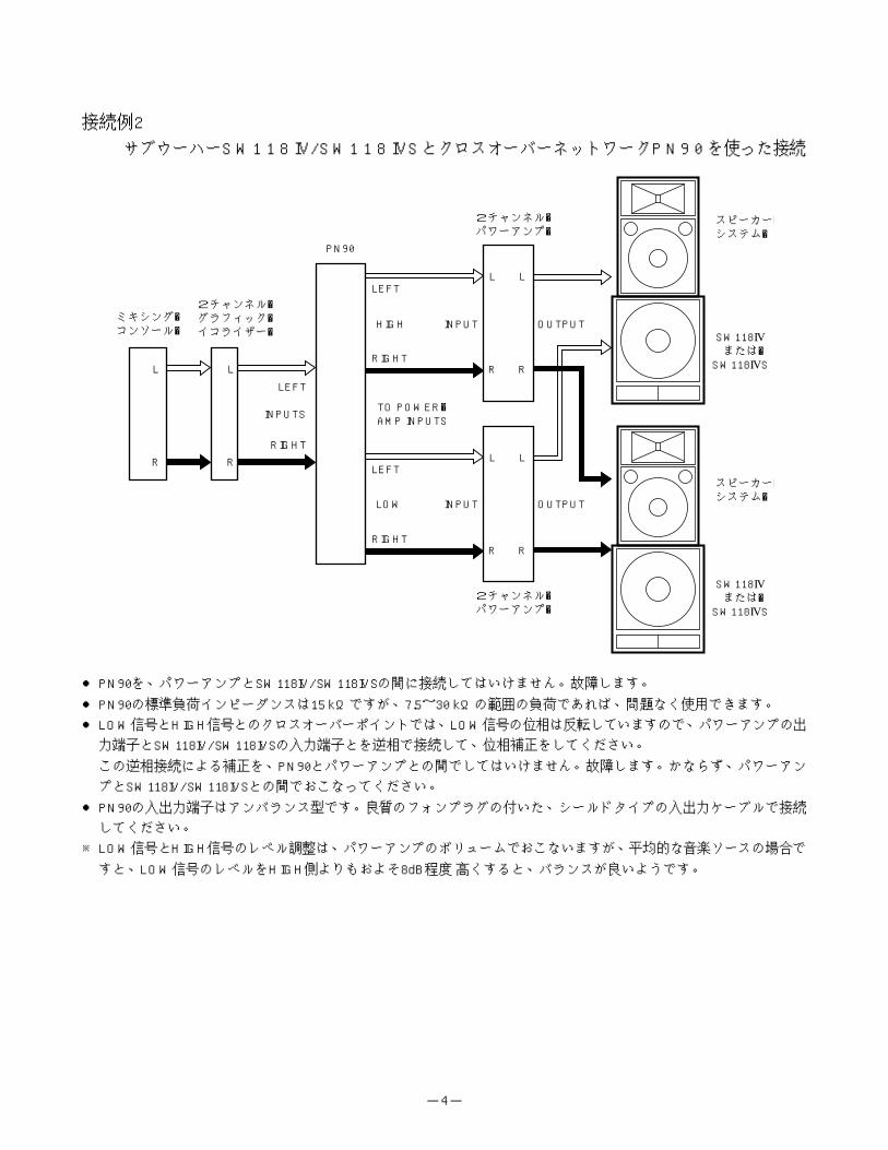
接続例2サブウーハーSW118IV/SW118IVSとクロスオーバーネットワークPN90を使った接続
ミキシングコンソール
2チャンネルグラフィックイコライザー
LEFT
INPUTS
RIGHT
PN90
LEFT
HIGH
RIGHT
INPUT
TO POWERAMP INPUTS
LEFT
RIGHT
LOW INPUT
2チャンネルパワーアンプ
2チャンネルパワーアンプ
OUTPUT
OUTPUT
スピーカーシステム
SW118IVまたはSW118IVS
SW118IVまたはSW118IVS
スピーカーシステム
L
R
L
R
L
R
L
R
L
R
L
R
PN90を、パワーアンプとSW118IV/SW118IVSの間に接続してはいけません。故障します。PN90の標準負荷インピーダンスは15 kΩですが、7.5~30 kΩの範囲の負荷であれば、問題なく使用できます。LOW信号とHIGH信号とのクロスオーバーポイントでは、LOW信号の位相は反転していますので、パワーアンプの出力端子とSW118IV/SW118IVSの入力端子とを逆相で接続して、位相補正をしてください。この逆相接続による補正を、PN90とパワーアンプとの間でしてはいけません。故障します。かならず、パワーアンプとSW118IV/SW118IVSとの間でおこなってください。
PN90の入出力端子はアンバランス型です。良質のフォンプラグの付いた、シールドタイプの入出力ケーブルで接続してください。
※LOW信号とHIGH信号のレベル調整は、パワーアンプのボリュームでおこないますが、平均的な音楽ソースの場合ですと、LOW信号のレベルをHIGH側よりもおよそ8dB程度 高くすると、バランスが良いようです。

W
H
D216
63.5
φ6.2
W
H
D
120˚
30˚
W
H
D
75˚ 105˚
-5-
S112IV, S112IVS,
S112IV-OAK,
S115IV, S115IVS,
S115IVA, S115IVAS,
S115IVA-OAK
SM10IV, SM10IV-OAK,
SM12IV, SM12IVS,
SM15IV, SM15IV-OAK
品 番 SW118IV/SW118IVSエンクロージャー バスレフ型スピーカーユニット 18"コーン再生周波数帯域 30Hz~2kHz許容入力 NOISE* 250W
PGM 500WMAX 1000W
公称インピーダンス 8Ω出力音圧レベル 96dB SPL (1W、1m)推奨クロスオーバー周波数 90Hz、12dB/oct.入力端子 フォンジャック×2最大外形寸法(W×H×D) 542×654×791 mm重 量 32.4 kg
W
H
D
品 番 SM10IV/SM10IV-OAKS112IV/S112IVS/SM12IV/SM12IVS/ S115IV/S115IVS/S115IVA/S115IVAS/
S112IV-OAK S115IVA-OAK/SM15IV/SM15IV-OAKエンクロージャー バスレフ型スピーカーユニット LF 10"コーン 12"コーン 15"コーン
HF 1"ドライバー 2"ドライバー再生周波数帯域 70Hz~20kHz 60Hz~16kHz 55Hz~16kHz許容入力 NOISE* 100W 150W 250W
PGM 200W 300W 500WMAX 400W 600W 1000W
公称インピーダンス 8Ω出力音圧レベル 95dB SPL (1W、1m) 97dB SPL (1W、1m) 99dB SPL (1W、1m)公称指向角度 水平 60゜ 90゜
垂直 40゜クロスオーバー周波数 1.8kHz 2kHz 1.7kHz入力端子 フォンジャック×2最大外形寸法(W×H×D) SM10IV:560×339×277 mm S112IV/S112IVS:400×638×318 mm S115IV/S115IVS/S115IVA/S115IVAS:475×712×362 mm
SM10IV-OAK: SM12IV/SM12IVS:643×402×344 mm SM15IV:720×485×345 mm 526×316×261 mm S112IV-OAK:400×620×318 mm S115IVA-OAK:479×695×360 mm SM15IV-OAK:695×479×340 mm
重 量 SM10IV: 12.2 kg S112IV/S112IVS:19.3 kg、 S115IV/S115IVS/S115IVA/S115IVAS:27.5 kg、SM10IV-OAK:10.5 kg SM12IV/SM12IVS:19.5 kg、 SM15IV:26 kg、
S112IV-OAK:18 kg S115IVA-OAK:27.5 kg、SM15IV-OAK:26 kg
仕様
品 番 PN90クロスオーバー周波数 90Hz、12dB/oct.(負荷15 kΩ)推奨負荷インピーダンス 15 kΩ (HF、LF)挿入時ロス 3dB入力端子 フォンジャック×2出力端子 フォンジャック×4最大外形寸法(W×H×D) 227×38×76 mm重 量 0.6 kg
単位:mm
*: EIA RS-426
仕様、外観は予告なく変更する場合があります。
SW118IV,
SW118IVS
PN90

テクニカルデータ
-6-
周波数特性/インピーダンス
• SM10IV/SM10IV-OAK
10k1k100204
8
16
FREQUENCY(Hz)
RES
PON
SE(
dB)
60
70
80
90
100
110
• S112IV/S112IVS/SM12IV/SM12IVS/S112IV-OAK
10k4
1k1002060
70
80
90
100
110
8
16
FREQUENCY(Hz)
RES
PON
SE(
dB)
• S115IV/S115IVS/S115IVA/S115IVAS/S115IVA-OAK/
SM15IV/SM15IV-OAK
10k1k100204
8
16
FREQUENCY(Hz)R
ESPO
NSE(
dB)
60
70
80
90
100
110
• SW118IV/SW118IVS
10k1k100204
8
16
FREQUENCY(Hz)
RES
PON
SE(
dB)
60
70
80
90
100
110

-7-
水平指向性(単体)
• SM10IV/SM10IV-OAK
0°
330°
300°
270°
240°
210°
180°
150°
120°
90°
50 50
60°
30°
40 40302010030 20 10 0
• 500Hz• 1kHz• 2kHz
• S112IV/S112IVS/SM12IV/SM12IVS/S112IV-OAK
0°
330°
300°
270°
240°
210°
180°
150°
120°
90°
50 50
60°
30°
40 40302010030 20 10 0
• 500Hz• 1kHz• 2kHz
0°
330°
300°
270°
240°
210°
180°
150°
120°
90°
50 50
60°
30°
40 40302010030 20 10 0
• 500Hz• 1kHz• 2kHz
0°
330°
300°
270°
240°
210°
180°
150°
120°
90°
50 50
60°
30°
40 40302010030 20 10 0
• 4kHz• 8kHz• 16kHz
0°
330°
300°
270°
240°
210°
180°
150°
120°
90°
50 50
60°
30°
40 40302010030 20 10 0
• 4kHz• 8kHz• 16kHz
0°
330°
300°
270°
240°
210°
180°
150°
120°
90°
50 50
60°
30°
40 40302010030 20 10 0
• 4kHz• 8kHz• 16kHz
• S115IV/S115IVS/S115IVA/S115IVAS/S115IVA-OAK/SM15IV/SM15IV-OAK
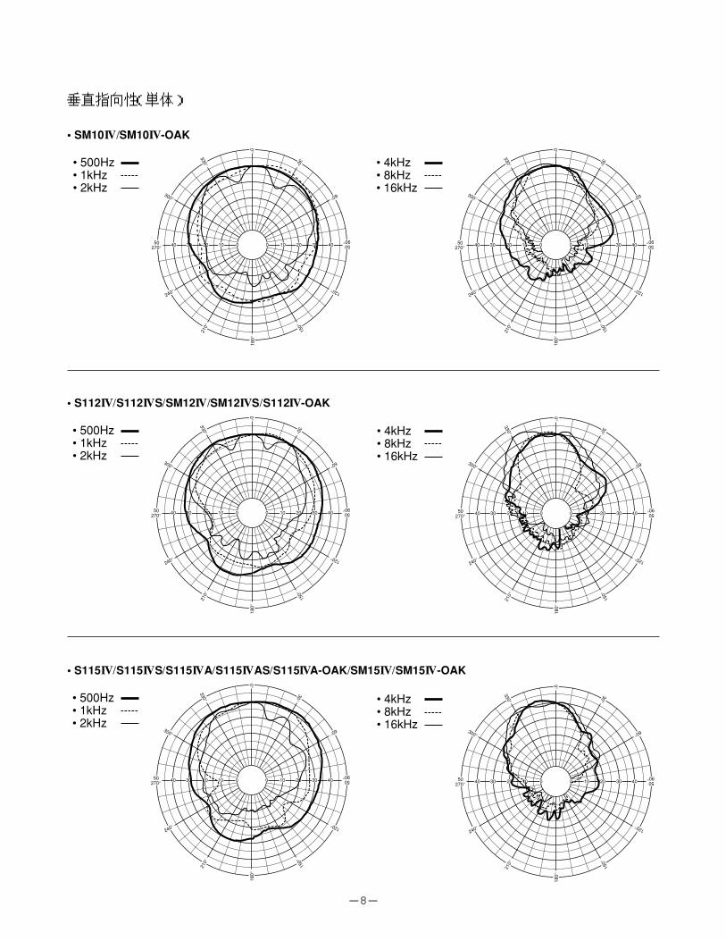
垂直指向性(単体)
• SM10IV/SM10IV-OAK
0°
330°
300°
270°
240°
210°
180°
150°
120°
90°
50 50
60°
30°
40 40302010030 20 10 0
• 500Hz• 1kHz• 2kHz
• S112IV/S112IVS/SM12IV/SM12IVS/S112IV-OAK
0°
330°
300°
270°
240°
210°
180°
150°
120°
90°
50 50
60°
30°
40 40302010030 20 10 0
• 500Hz• 1kHz• 2kHz
0°
330°
300°
270°
240°
210°
180°
150°
120°
90°
50 50
60°
30°
40 40302010030 20 10 0
• 500Hz• 1kHz• 2kHz
0°
330°
300°
270°
240°
210°
180°
150°
120°
90°
50 50
60°
30°
40 40302010030 20 10 0
• 4kHz• 8kHz• 16kHz
0°
330°
300°
270°
240°
210°
180°
150°
120°
90°
50 50
60°
30°
40 40302010030 20 10 0
• 4kHz• 8kHz• 16kHz
0°
330°
300°
270°
240°
210°
180°
150°
120°
90°
50 50
60°
30°
40 40302010030 20 10 0
• 4kHz• 8kHz• 16kHz
-8-
• S115IV/S115IVS/S115IVA/S115IVAS/S115IVA-OAK/SM15IV/SM15IV-OAK

サービスについて
PA営業部PA営業課 † 03-5488-5472 108-8568 東京都港区高輪2-17-11
-9-
お客様ご相談窓口 : ヤマハプロオーディオ製品に対するお問合せ窓口
ヤマハ・プロオーディオ・インフォメーションセンターTel: 03-5791-7678 Fax: 03-5488-5085(電話受付=祝祭日を除く月~金/11:00~19:00)E-mail: [email protected]
営業窓口
PA営業部 011-512-6106 064-0810 札幌市中央区南十条西1-1-50 022-222-6214 980-0804 仙台市青葉区大町2-2-10 03-5488-5480 108-8568 東京都港区高輪2-17-11 052-232-5744 460-8588 名古屋市中区錦1-18-28 06-6647-8359 556-0011 大阪市浪速区難波中1-13-17 092-412-5556 812-8508 福岡市博多区博多駅前2-11-4 03-5488-5472 108-8568 東京都港区高輪2-17-11 053-460-2455 430-8650 浜松市中沢町10-1
ヤマハ電気音響製品サービス拠点 : 修理受付および修理品お預かり窓口
北海道サービスステーション 011-512-6108 064-8543 札幌市中央区南十条西1-1-50 ヤマハセンター内仙 台サービスステーション 022-236-0249 984-0015 仙台市若林区卸町5-7 仙台卸商共同配送センター 3F首都圏サービスセンター 03-5762-2121 143-0006 東京都大田区平和島2-1-1 京阪トラックターミナル14号棟A-5F浜 松サービスステーション 053-465-6711 435-0016 浜松市和田町200 ヤマハ(株)和田工場6号館2階名古屋サービスセンター 052-652-2230 454-0058 名古屋市中川区玉川町2-1-2 ヤマハ(株)名古屋流通センター3F大 阪サービスセンター 06-6877-5262 565-0803 吹田市新芦屋下1-16 ヤマハ(株)千里丘センター内四 国サービスステーション 087-822-3045 760-0029 高松市丸亀町8-7 (株)ヤマハミュージック神戸 高松店内広 島サービスステーション 082-874-3787 731-0113 広島市安佐南区西原6-14-14九 州サービスステーション 092-472-2134 812-8508 福岡市博多区博多駅前2-11-4本 社/CSセンター 053-465-1158 435-0016 浜松市和田町200 ヤマハ(株)和田工場6号館2階
※ 所在地・電話番号などは変更されることがあります。※ 2001年5月現在
保証書この商品には保証書がついています。販売店でお渡ししてい
ますから、ご住所・お名前・お買上げ年月日・販売店名など所定事項の記入および記載内容をおたしかめのうえ、大切に保管してください。
保証書は当社がお客様に保証期間内の無償サービスをお約束するもので、この商品の保証期間はお買上げ日より1年です。
保証期間内の転居や、ご贈答用に購入された場合などで、記載事項の変更が必要なときは、事前・事後を問わずお買上げ販売店かお客様ご相談窓口、またはヤマハ電気音響製品サービス拠点へご連絡ください。継続してサービスできるように手配いたします。
損害に対する責任この商品(搭載プログラムを含む)の使用または使用不能に
より、お客様に生じた損害(事業利益の損失、事業の中断、事業情報の損失、その他の特別損失や逸失利益)については、当社は一切その責任を負わないものとします。また、如何なる場合でも、当社が負担する損害賠償額は、お客様がお支払になったこの商品の代価相当額をもって、その上限とします。
調整・故障の修理「故障かな?」と思われる症状のときは、この説明書をもう一度
よくお読みになり、電源・接続・操作などをおたしかめください。それでもなお改善されないときには、お買上げ販売店へご連絡ください。調整・修理いたします。
調整・修理にさいしては保証書をご用意ください。保証規定により、調整・修理サービスをいたします。また、故障した製品をお持ちいただくか、サービスにお伺いするのかも保証書に書かれています。
修理サービスは保証期間が過ぎた後も引き続きおこなわれ、そのための補修用性能部品が用意されています。性能部品とは製品の機能を維持するために不可欠な部品のことをいい、PA製品ではその最低保有期間は製造打切後8年です。この期間は経済産業省の指導によるものです。
お客様ご相談窓口ヤマハPA製品にかんするご質問・ご相談は下記のお客様ご
相談窓口へ、アフターサービスについてのお問合わせはヤマハ電気音響製品サービス拠点へおよせください。
北 海 道 営 業 所仙 台 営 業 所東 京 事 業 所名 古 屋 営 業 所大 阪 事 業 所九 州 営 業 所P A 営 業 課P A 推 進 室


