A
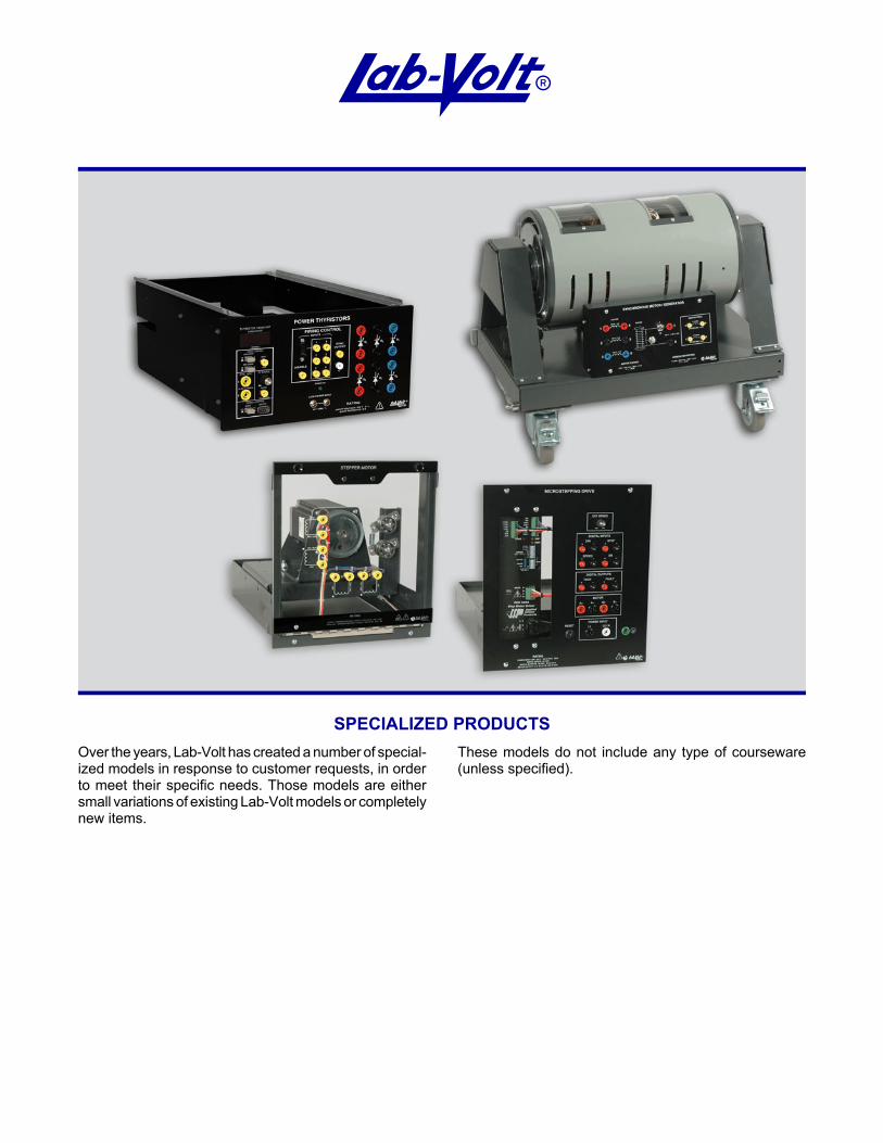
SPECIALIZED PRODUCTSOver the years, Lab-Volt has created a number of special-ized models in response to customer requests, in orderto meet their specific needs. Those models are eithersmall variations of existing Lab-Volt models or completelynew items.
These models do not include any type of courseware(unless specified).

1 These products were created in response to customer requests for specific needs and do not include any courseware.
(732) 938-2000 / 800-LAB-VOLT, FAX: (732) 774-8573, E-MAIL: [email protected](418) 849-1000 / 800-LAB-VOLT, FAX: (418) 849-1666, E-MAIL: [email protected]
INTERNET: http: //www.labvolt.com
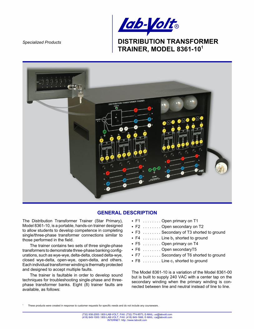
ASpecialized Products DISTRIBUTION TRANSFORMER
TRAINER, MODEL 8361-101
GENERAL DESCRIPTIONThe Distribution Transformer Trainer (Star Primary),Model 8361-10, is a portable, hands-on trainer designedto allow students to develop competence in completingsingle/three-phase transformer connections similar tothose performed in the field.
The trainer contains two sets of three single-phasetransformers to demonstrate three-phase banking config-urations, such as wye-wye, delta-delta, closed delta-wye,closed wye-delta, open-wye, open-delta, and others.Each individual transformer winding is thermally protectedand designed to accept multiple faults.
The trainer is faultable in order to develop soundtechniques for troubleshooting single-phase and three-phase transformer banks. Eight (8) trainer faults areavailable, as follows:
C F1 . . . . . . . . Open primary on T1C F2 . . . . . . . . Open secondary on T2C F3 . . . . . . . . Secondary of T3 shorted to groundC F4 . . . . . . . . Line b1 shorted to groundC F5 . . . . . . . . Open primary on T4C F6 . . . . . . . . Open secondaryT5C F7 . . . . . . . . Secondary of T6 shorted to groundC F8 . . . . . . . . Line c1 shorted to ground
The Model 8361-10 is a variation of the Model 8361-00but is built to supply 240 VAC with a center tap on thesecondary winding when the primary winding is con-nected between line and neutral instead of line to line.
SPECIALIZED PRODUCTS
1 Various versions are available. Refer to Ordering Numbers section.
4
SPECIFICATIONSModel 8361-101 – Distribution Transformer Trainer (Star Pri-mary) 120/208 V – 60 Hz 220/380 V – 50 Hz 240/415 V – 50 Hz
Input Voltage 120/208 V 220/380 V 240/415 V
Phases 3
Wires 4 wires plus ground
Current rating 5 A 3 A 3 A
Transformers Primary Voltage 120 V 220 V 240 V
Secondary Voltage 120/120 V
Power Capacity 25 VA
Quantity 6
Protection Thermal Circuit Breaker
Service Lines 2 sets of three lines + neutral
Load Lamps Quantity 3
Rated Voltage 250 V
Rated Power 25 W
Test Leads 2 (probe type)
Faults Quantity 8 (switch insertable)
Accessibility Through locked door at the back of the trainer
Physical Characteristics Dimensions (H x W x D) 340 x 491 x 253 mm (13.4 x 19.3 x 10.0 in)
Net weight 24 kg (53 lb)
ORDERING NUMBERS
120/208 V – 60 Hz 220/380 V – 50 Hz 240/415 V – 50Hz
ENGLISH FRENCH SPANISH ENGLISH FRENCH SPANISH ENGLISH8361-10 8361-11 8361-12 8361-15 8361-16 8361-17 8361-1A
Table 1. Equipment Ordering Numbers
1 These products were created in response to customer requests for specific needs and do not include any courseware (other than manufacturer user manuals).
5
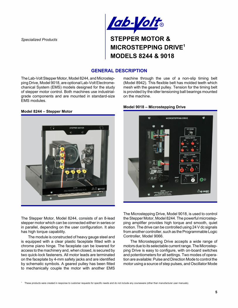
ASpecialized Products STEPPER MOTOR &
MICROSTEPPING DRIVE1
MODELS 8244 & 9018
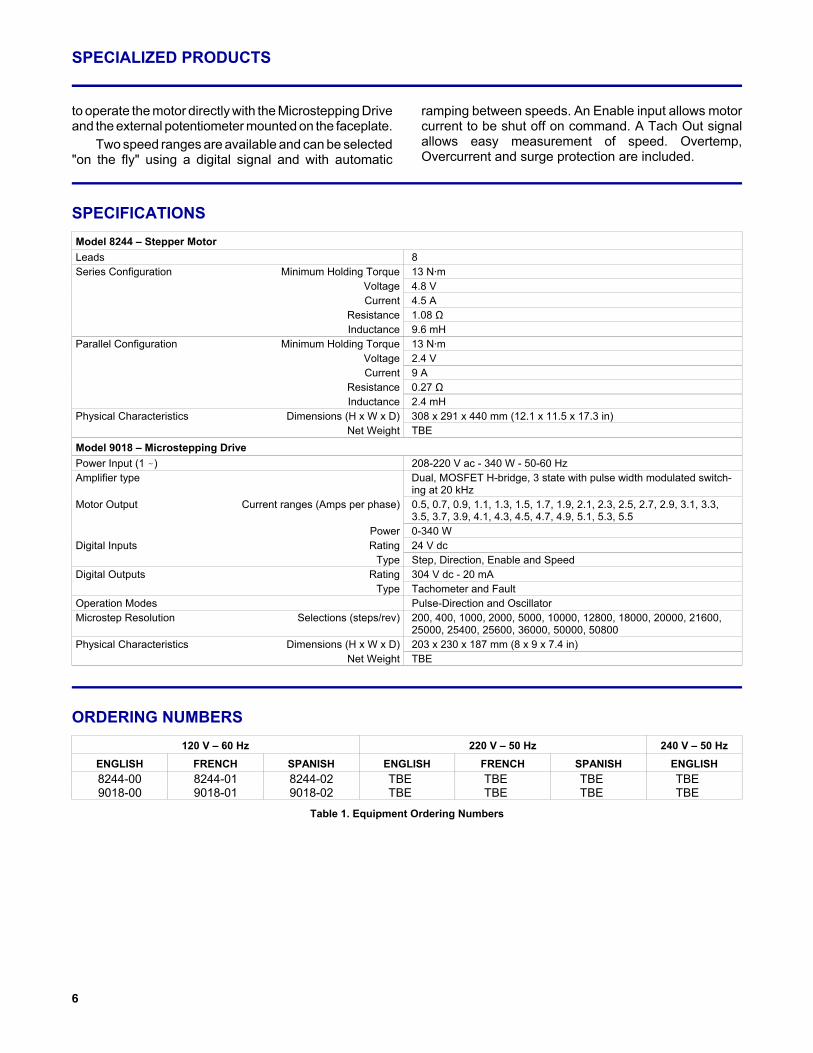
GENERAL DESCRIPTIONThe Lab-Volt Stepper Motor, Model 8244, and Microstep-ping Drive, Model 9018, are optional Lab-Volt Electrome-chanical System (EMS) models designed for the studyof stepper motor control. Both machines use industrial-grade components and are mounted in standard-sizeEMS modules.
Model 8244 – Stepper Motor
The Stepper Motor, Model 8244, consists of an 8-leadstepper motor which can be connected either in series orin parallel, depending on the user configuration. It alsohas high torque capability.
The module is constructed of heavy gauge steel andis equipped with a clear plastic faceplate fitted with achrome piano hinge. The faceplate can be lowered foraccess to the machinery and, when closed, is secured bytwo quick-lock fasteners. All motor leads are terminatedon the faceplate by 4-mm safety jacks and are identifiedby schematic symbols. A geared pulley has been fittedto mechanically couple the motor with another EMS
machine through the use of a non-slip timing belt(Model 8942). This flexible belt has molded teeth whichmesh with the geared pulley. Tension for the timing beltis provided by the idler tensioning ball bearings mountedon the machine.
Model 9018 – Microstepping Drive
The Microstepping Drive, Model 9018, is used to controlthe Stepper Motor, Model 8244. The powerful microstep-ping amplifier provides high torque and smooth, quietmotion. The drive can be controlled using 24 V dc signalsfrom another controller, such as the Programmable LogicController, Model 9066.
The Microstepping Drive accepts a wide range ofmotors due to its selectable current range. The Microstep-ping Drive is easy to configure, with on-board switchesand potentiometers for all settings. Two modes of opera-tion are available: Pulse and Direction Mode to control themotor using a source of step pulses, and Oscillator Mode
SPECIALIZED PRODUCTS
6
to operate the motor directly with the Microstepping Driveand the external potentiometer mounted on the faceplate.
Two speed ranges are available and can be selected"on the fly" using a digital signal and with automatic
ramping between speeds. An Enable input allows motorcurrent to be shut off on command. A Tach Out signalallows easy measurement of speed. Overtemp,Overcurrent and surge protection are included.
SPECIFICATIONSModel 8244 – Stepper MotorLeads 8Series Configuration Minimum Holding Torque 13 N@m
Voltage 4.8 VCurrent 4.5 A
Resistance 1.08 ΩInductance 9.6 mH
Parallel Configuration Minimum Holding Torque 13 N@mVoltage 2.4 VCurrent 9 A
Resistance 0.27 ΩInductance 2.4 mH
Physical Characteristics Dimensions (H x W x D) 308 x 291 x 440 mm (12.1 x 11.5 x 17.3 in)Net Weight TBE
Model 9018 – Microstepping DrivePower Input (1 -) 208-220 V ac - 340 W - 50-60 HzAmplifier type Dual, MOSFET H-bridge, 3 state with pulse width modulated switch-
ing at 20 kHzMotor Output Current ranges (Amps per phase) 0.5, 0.7, 0.9, 1.1, 1.3, 1.5, 1.7, 1.9, 2.1, 2.3, 2.5, 2.7, 2.9, 3.1, 3.3,
3.5, 3.7, 3.9, 4.1, 4.3, 4.5, 4.7, 4.9, 5.1, 5.3, 5.5Power 0-340 W
Digital Inputs Rating 24 V dcType Step, Direction, Enable and Speed
Digital Outputs Rating 304 V dc - 20 mAType Tachometer and Fault
Operation Modes Pulse-Direction and OscillatorMicrostep Resolution Selections (steps/rev) 200, 400, 1000, 2000, 5000, 10000, 12800, 18000, 20000, 21600,
25000, 25400, 25600, 36000, 50000, 50800Physical Characteristics Dimensions (H x W x D) 203 x 230 x 187 mm (8 x 9 x 7.4 in)
Net Weight TBE
ORDERING NUMBERS120 V – 60 Hz 220 V – 50 Hz 240 V – 50 Hz
ENGLISH FRENCH SPANISH ENGLISH FRENCH SPANISH ENGLISH8244-00 8244-01 8244-02 TBE TBE TBE TBE9018-00 9018-01 9018-02 TBE TBE TBE TBE
Table 1. Equipment Ordering Numbers
1 These products were created in response to customer requests for specific needs and do not include any courseware (other than manufacturer user manuals).
7
ASpecialized Products SINGLE-PHASE TRANSFORMER1
MODEL 8341-SP
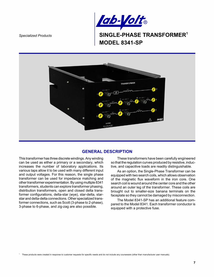
GENERAL DESCRIPTIONThis transformer has three discrete windings. Any windingcan be used as either a primary or a secondary, whichincreases the number of laboratory applications. Itsvarious taps allow it to be used with many different inputand output voltages. For this reason, the single phasetransformer can be used for impedance matching andother transformer experimentation. By using multiple 8341transformers, students can explore transformer phasing,distribution transformers, open and closed delta trans-former configurations, delta-star (wye), star-delta, star-star and delta-delta connections. Other specialized trans-former connections, such as Scott (3-phase to 2-phase),3-phase to 6-phase, and zig-zag are also possible.
These transformers have been carefully engineeredso that the regulation curves produced by resistive, induc-tive, and capacitive loads are readily distinguishable.
As an option, the Single-Phase Transformer can beequipped with two search coils, which allows observationof the magnetic flux waveform in the iron core. Onesearch coil is wound around the center core and the otheraround an outer leg of the transformer. These coils arebrought out to smaller-size banana terminals on thefaceplate so they cannot be damaged by misconnection.
The Model 8341-SP has an additional feature com-pared to the Model 8341. Each transformer conductor isequipped with a protective fuse.
SPECIALIZED PRODUCTS
1TBE = To Be Established
8
SPECIFICATIONSModel 8341 – Single-Phase Transformer 120/208 V – 60 Hz 220/380 V – 50 Hz 240/415 V – 50 HzCoil 1 Rating Voltage 120 V – AC 220 V – AC 240 V – AC
Current 0.5 A 0.25 A 0.25 A
Coil 2 Rating Voltage 208 V 380 V 415 V
Current 0.3 A 0.15 A 0.15 A
Taps 50% and 86,6%
Coil 3 Rating Voltage 120 V – AC 220 V – AC 240 V – AC
Current 0.5 A 0.25 A 0.25 A
Taps 50%
Search Coils Center Core 20 turns TBE1
Outer Leg 20 turns TBE
Fuses (6) 0.5 A SB (3),0.375 A SB (3)
TBE
Physical Characteristics Dimensions (H x W x D) 154 x 287 x 440 mm (6.1 x 11.3 x 17.3 in)
Net Weight 6.5 kg (14.3 lb)
1 These products were created in response to customer requests for specific needs and do not include any courseware (other than manufacturer user manuals).
9
ASpecialized Products POWER THYRISTORS1
MODEL 8841-SP
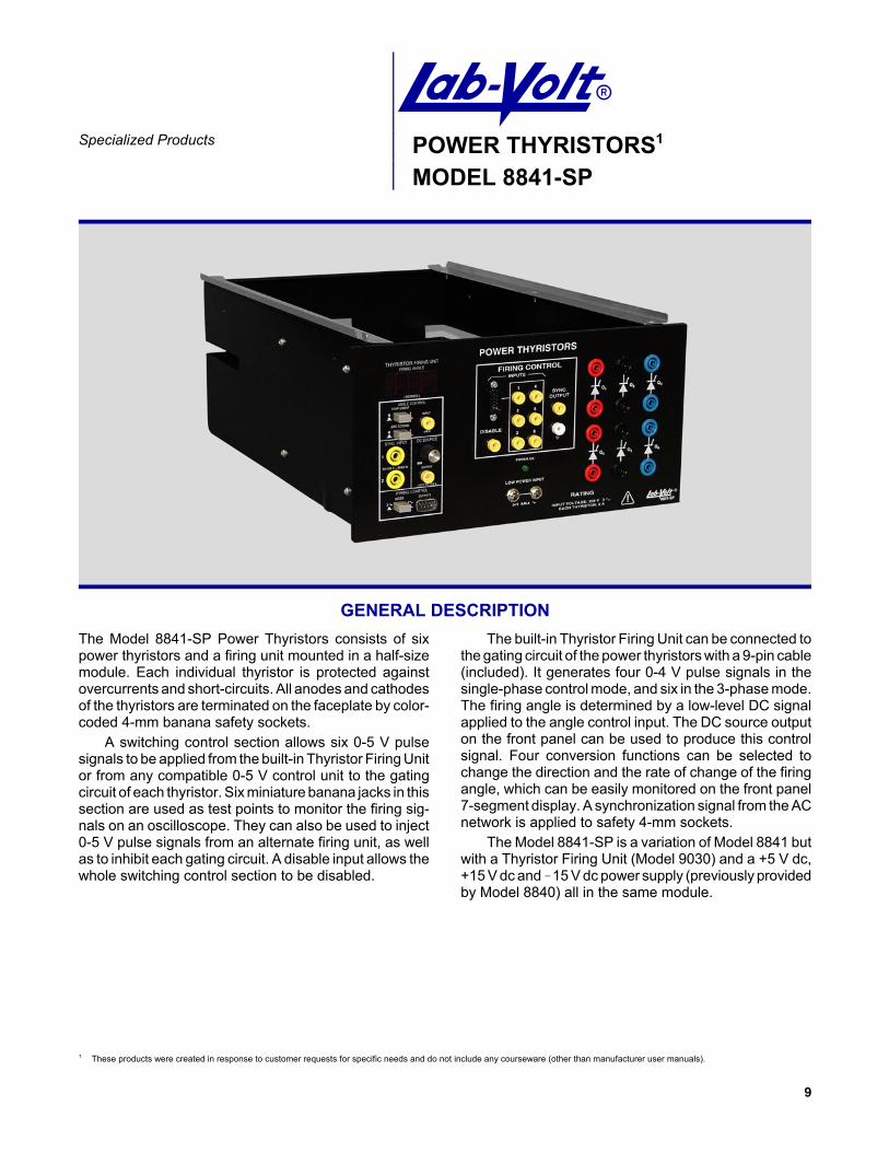
GENERAL DESCRIPTIONThe Model 8841-SP Power Thyristors consists of sixpower thyristors and a firing unit mounted in a half-sizemodule. Each individual thyristor is protected againstovercurrents and short-circuits. All anodes and cathodesof the thyristors are terminated on the faceplate by color-coded 4-mm banana safety sockets.
A switching control section allows six 0-5 V pulsesignals to be applied from the built-in Thyristor Firing Unitor from any compatible 0-5 V control unit to the gatingcircuit of each thyristor. Six miniature banana jacks in thissection are used as test points to monitor the firing sig-nals on an oscilloscope. They can also be used to inject0-5 V pulse signals from an alternate firing unit, as wellas to inhibit each gating circuit. A disable input allows thewhole switching control section to be disabled.
The built-in Thyristor Firing Unit can be connected tothe gating circuit of the power thyristors with a 9-pin cable(included). It generates four 0-4 V pulse signals in thesingle-phase control mode, and six in the 3-phase mode.The firing angle is determined by a low-level DC signalapplied to the angle control input. The DC source outputon the front panel can be used to produce this controlsignal. Four conversion functions can be selected tochange the direction and the rate of change of the firingangle, which can be easily monitored on the front panel7-segment display. A synchronization signal from the ACnetwork is applied to safety 4-mm sockets.
The Model 8841-SP is a variation of Model 8841 butwith a Thyristor Firing Unit (Model 9030) and a +5 V dc,+15 V dc and !15 V dc power supply (previously providedby Model 8840) all in the same module.
SPECIALIZED PRODUCTS
10
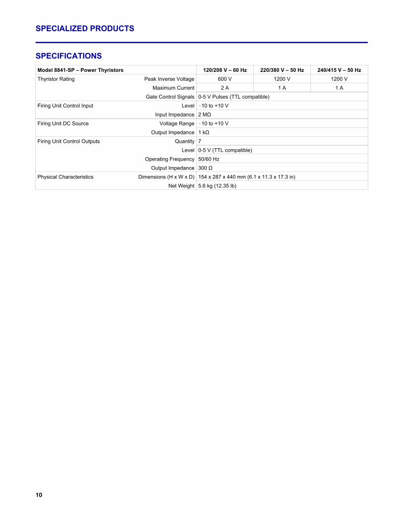
SPECIFICATIONSModel 8841-SP – Power Thyristors 120/208 V – 60 Hz 220/380 V – 50 Hz 240/415 V – 50 HzThyristor Rating Peak Inverse Voltage 600 V 1200 V 1200 V
Maximum Current 2 A 1 A 1 A
Gate Control Signals 0-5 V Pulses (TTL compatible)
Firing Unit Control Input Level !10 to +10 V
Input Impedance 2 MΩ
Firing Unit DC Source Voltage Range !10 to +10 V
Output Impedance 1 kΩ
Firing Unit Control Outputs Quantity 7
Level 0-5 V (TTL compatible)
Operating Frequency 50/60 Hz
Output Impedance 300 Ω
Physical Characteristics Dimensions (H x W x D) 154 x 287 x 440 mm (6.1 x 11.3 x 17.3 in)
Net Weight 5.6 kg (12.35 lb)
1 These products were created in response to customer requests for specific needs and do not include any courseware.
11
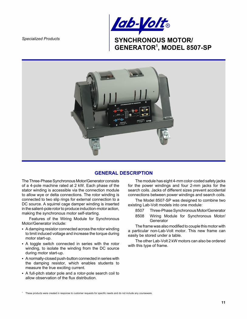
ASpecialized Products SYNCHRONOUS MOTOR/
GENERATOR1, MODEL 8507-SP
GENERAL DESCRIPTIONThe Three-Phase Synchronous Motor/Generator consistsof a 4-pole machine rated at 2 kW. Each phase of thestator winding is accessible via the connection moduleto allow wye or delta connections. The rotor winding isconnected to two slip rings for external connection to aDC source. A squirrel cage damper winding is insertedin the salient-pole rotor to produce induction-motor action,making the synchronous motor self-starting.
Features of the Wiring Module for SynchronousMotor/Generator include:C A damping resistor connected across the rotor winding
to limit induced voltage and increase the torque duringmotor start-up.
C A toggle switch connected in series with the rotorwinding, to isolate the winding from the DC sourceduring motor start-up.
C A normally-closed push-button connected in series withthe damping resistor, which enables students tomeasure the true exciting current.
C A full-pitch stator pole and a rotor-pole search coil toallow observation of the flux distribution.
The module has eight 4-mm color-coded safety jacksfor the power windings and four 2-mm jacks for thesearch coils. Jacks of different sizes prevent accidentalconnections between power windings and search coils.
The Model 8507-SP was designed to combine twoexisting Lab-Volt models into one module:
8507 Three-Phase Synchronous Motor/Generator8508 Wiring Module for Synchronous Motor/
GeneratorThe frame was also modified to couple this motor with
a particular non-Lab-Volt motor. This new frame caneasily be stored under a table.
The other Lab-Volt 2 kW motors can also be orderedwith this type of frame.
SPECIALIZED PRODUCTS
12
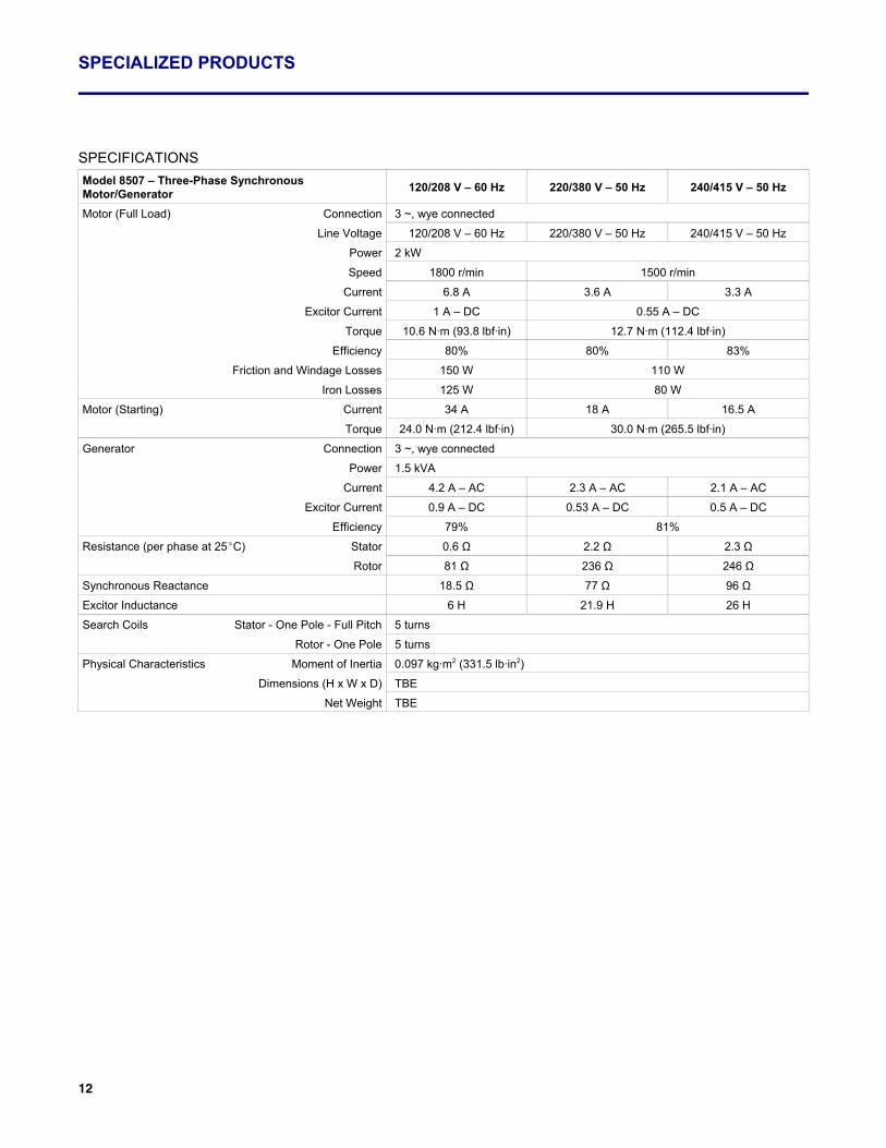
SPECIFICATIONSModel 8507 – Three-Phase SynchronousMotor/Generator 120/208 V – 60 Hz 220/380 V – 50 Hz 240/415 V – 50 Hz
Motor (Full Load) Connection 3 ~, wye connected
Line Voltage 120/208 V – 60 Hz 220/380 V – 50 Hz 240/415 V – 50 Hz
Power 2 kW
Speed 1800 r/min 1500 r/min
Current 6.8 A 3.6 A 3.3 A
Excitor Current 1 A – DC 0.55 A – DC
Torque 10.6 N·m (93.8 lbf·in) 12.7 N·m (112.4 lbf·in)
Efficiency 80% 80% 83%
Friction and Windage Losses 150 W 110 W
Iron Losses 125 W 80 W
Motor (Starting) Current 34 A 18 A 16.5 A
Torque 24.0 N·m (212.4 lbf·in) 30.0 N·m (265.5 lbf·in)
Generator Connection 3 ~, wye connected
Power 1.5 kVA
Current 4.2 A – AC 2.3 A – AC 2.1 A – AC
Excitor Current 0.9 A – DC 0.53 A – DC 0.5 A – DC
Efficiency 79% 81%
Resistance (per phase at 25EC) Stator 0.6 Ω 2.2 Ω 2.3 Ω
Rotor 81 Ω 236 Ω 246 Ω
Synchronous Reactance 18.5 Ω 77 Ω 96 Ω
Excitor Inductance 6 H 21.9 H 26 H
Search Coils Stator - One Pole - Full Pitch 5 turns
Rotor - One Pole 5 turns
Physical Characteristics Moment of Inertia 0.097 kg·m2 (331.5 lb·in2)
Dimensions (H x W x D) TBE
Net Weight TBE
1 These products were created in response to customer requests for specific needs and do not include any courseware (other than manufacturer user manuals).
13
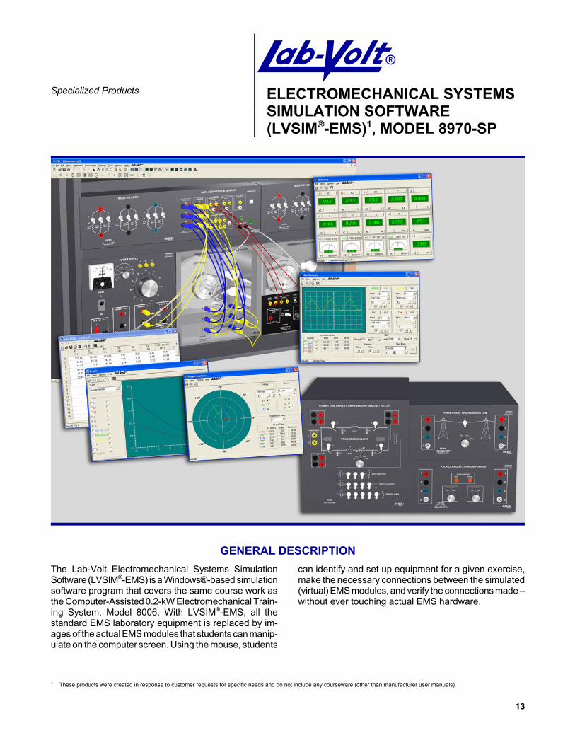
ASpecialized Products ELECTROMECHANICAL SYSTEMS
SIMULATION SOFTWARE(LVSIM®-EMS)1, MODEL 8970-SP
GENERAL DESCRIPTIONThe Lab-Volt Electromechanical Systems SimulationSoftware (LVSIM®-EMS) is a Windows®-based simulationsoftware program that covers the same course work asthe Computer-Assisted 0.2-kW Electromechanical Train-ing System, Model 8006. With LVSIM®-EMS, all thestandard EMS laboratory equipment is replaced by im-ages of the actual EMS modules that students can manip-ulate on the computer screen. Using the mouse, students
can identify and set up equipment for a given exercise,make the necessary connections between the simulated(virtual) EMS modules, and verify the connections made –without ever touching actual EMS hardware.

SPECIALIZED PRODUCTS
14
The Model 8970-SP is a variation of the LVSIM®-EMSsoftware. It includes 3 new modules for the analysis oftransmission lines:
Model 8362-A0 – Power Line Series CompensationDemonstratorModel 8370 – Three-Phase Transmission LineModel 8371 – Regulating Autotransformer
The Model 8970-SP is available in 120 V only. Thethree new modules are not documented in the on-linehelp of the software.
For further information, please consult the datasheetfor the Model 8970, LVSIM®-EMS.
1 These products were created in response to customer requests for specific needs and do not include any courseware (other than manufacturer user manuals).
15
ASpecialized Products FOUR-POLE CAGE INDUCTION
WITH RESISTANCE TEMPERATUREDETECTORS (RTD), MODEL 8503-SPWIRING MODULES, MODEL 8504-SP1
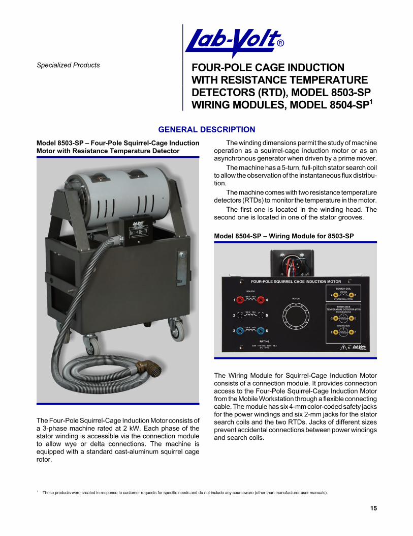
GENERAL DESCRIPTIONModel 8503-SP – Four-Pole Squirrel-Cage InductionMotor with Resistance Temperature Detector
The Four-Pole Squirrel-Cage Induction Motor consists ofa 3-phase machine rated at 2 kW. Each phase of thestator winding is accessible via the connection moduleto allow wye or delta connections. The machine isequipped with a standard cast-aluminum squirrel cagerotor.
The winding dimensions permit the study of machineoperation as a squirrel-cage induction motor or as anasynchronous generator when driven by a prime mover.
The machine has a 5-turn, full-pitch stator search coilto allow the observation of the instantaneous flux distribu-tion.
The machine comes with two resistance temperaturedetectors (RTDs) to monitor the temperature in the motor.
The first one is located in the winding head. Thesecond one is located in one of the stator grooves.
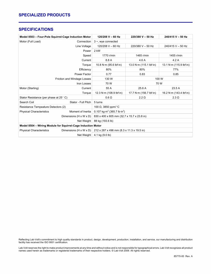
Model 8504-SP – Wiring Module for 8503-SP
The Wiring Module for Squirrel-Cage Induction Motorconsists of a connection module. It provides connectionaccess to the Four-Pole Squirrel-Cage Induction Motorfrom the Mobile Workstation through a flexible connectingcable. The module has six 4-mm color-coded safety jacksfor the power windings and six 2-mm jacks for the statorsearch coils and the two RTDs. Jacks of different sizesprevent accidental connections between power windingsand search coils.
SPECIALIZED PRODUCTS
Reflecting Lab-Volt's commitment to high quality standards in product, design, development, production, installation, and service, our manufacturing and distributionfacility has received the ISO 9001 certification.
Lab-Volt reserves the right to make product improvements at any time and without notice and is not responsible for typographical errors. Lab-Volt recognizes all productnames used herein as trademarks or registered trademarks of their respective holders. © Lab-Volt 2009. All rights reserved.
85770-00 Rev. A
SPECIFICATIONSModel 8503 – Four-Pole Squirrel-Cage Induction Motor 120/208 V – 60 Hz 220/380 V – 50 Hz 240/415 V – 50 HzMotor (Full Load) Connection 3 ~, wye connected
Line Voltage 120/208 V – 60 Hz 220/380 V – 50 Hz 240/415 V – 50 Hz
Power 2 kW
Speed 1770 r/min 1465 r/min 1455 r/min
Current 8.8 A 4.6 A 4.2 A
Torque 10.8 N·m (95.6 lbf·in) 13.0 N·m (115.1 lbf·in) 13.1 N·m (115.9 lbf·in)
Efficiency 80% 80% 77%
Power Factor 0.77 0.83 0.85
Friction and Windage Losses 130 W 100 W
Iron Losses 70 W 70 W
Motor (Starting) Current 55 A 25.6 A 23.5 A
Torque 12.3 N·m (108.9 lbf·in) 17.7 N·m (156.7 lbf·in) 16.2 N·m (143.4 lbf·in)
Stator Resistance (per phase at 25E C) 0.6 Ω 2.2 Ω 2.3 Ω
Search Coil Stator - Full Pitch 5 turns
Resistance Tempeature Detectors (2) 100 Ω, 3850 ppm/EC
Physical Characteristics Moment of Inertia 0.107 kg·m2 (365.7 lb·in2)
Dimensions (H x W x D) 830 x 400 x 605 mm (32.7 x 15.7 x 23.8 in)
Net Weight 88 kg (193.6 lb)
Model 8504 – Wiring Module for Squirrel-Cage Induction MotorPhysical Characteristics Dimensions (H x W x D) 212 x 287 x 496 mm (8.3 x 11.3 x 19.5 in)
Net Weight 4.1 kg (9.0 lb)


