
CSM_E2E_DS_E_7_1
Standard Proximity Sensor
E2E Your Search for Proximity Sensors Starts with the World-leading Performance and Quality of the E2E • Standard Sensors for detecting ferrous metals. • Wide array of variations. Ideal for a variety of applications. • Models with different frequencies are also available to prevent
mutual interference. • Superior environment resistance with standard cable made of oil-
resistant PVC and sensing surface made of material that resists cutting oil.
• Useful to help prevent disconnection. Cable protector provided as a standard feature.
Be sure to read Safety Precautions on page 27.
*1: No AC/DC 2-wire models or AC 2-wire M8 models are compliant. *2: Attach three ferrite clamps to the cable of the E2E-X3@@ and
E2E-X8MD@. (Refer to information on TDK catalog number ZCAT2035-0930A.)
*1, *2
Features
2-Wire Models
Pre-wired Models with Oil-resistant Reinforced PUR Cables Added
to the Lineup and Easy Differentiation with Orange Head
Oil ResistanceOil Resistance Cable FlexibilityCable FlexibilityCable FlexibilityCable Flexibility atCable Flexibility at Low TemperaturesLow TemperaturesOil ResistanceCable Flexibility at Low Temperatures
Differentiation from standard Oil Resistance (Insulation service life): Cable Flexibility: More Flexibility at −40°C models: Orange Head twice or three times approximately twice
that of oil-resistant vinyl chloride that of cinyl chloride cables
Lineup includes models with Smartclick pre-wired connectors for fast connection.
XS5 Smartclick connectors used to enable checking connector mating
Jacket: Polyester elastomer
Insulation: Oil-resistant grade PUR (polyurethane) 1/8 turn
Insert all the way.
Cl ick
1

E2E
Lineup includes models with self-diagnostic output to provide notification of failures and unstable detection conditions, such as coil burnout. • Contributes to preventive maintenance to keep the line from stopping.
Reduced wiring, fewer resources, and low power consumption contribute to environmentalism. • Wiring work and amount of copper wire used reduced to two thirds of that required for 3-wire models. • Current consumption drastically reduced to less than 10% (when a DC 2-wire model is compared with a DC 3-wire model).
3-Wire Models
Lineup includes models with small diameter (3 dia., 4 dia., 5.4 dia., M5) • All small-diameter models use sealed construction. Operation is stable even when the Sensor is mounted in a small space or embedded in metal. • Bright indicators enable easily checking the installation condition.
Wide range of ambient operating temperatures: −40°C to 85°C (M8 to M30 models) • Wide range of ambient operating temperatures also for small-diameter models: −25°C to 70°C • Suitable for low-temperature and high-temperature applications, which are troublesome for photoelectric sensors.
Lineup includes models with flexible cable (4-dia. to M30 models) • Reduced risk of disconnection in applications with moving parts.
2

-
-
E2E Models Listed by E2E Type
●: Standard Models, ▲: Different frequency, @: Self-diagnosis, ■: Different frequency and self-diagnosis, ---: Not listed
2-Wire Models
Po
wer
sup
ply
Sh
ield
ing
Siz
e an
d s
ensi
ng
dis
tan
ce
Po
lari
ty
Op
erat
ion
mo
de
Oil resistant reinforced PUR cable
Standard cable and flexible cable (cable material: oil resistant PVC)/Connector models Page
M12
pre
-wir
ed
smar
tclic
kco
nn
ecto
r m
od
els
Pre
-wir
ed m
od
el
wit
h 2
-m c
able
M12
pre
-wir
ed
smar
tclic
kco
nn
ecto
r m
od
els
Pre
-wir
ed m
od
el
wit
h s
tan
dar
d2-
m c
able
Pre
-wir
ed m
od
el
wit
h f
lexi
ble
2-m
cab
le
Pre
-wir
ed m
od
el
wit
h s
tan
dar
d5-
m c
able
M12
co
nn
ecto
r (I
EC
p
in a
rran
gem
ent)
M12
sta
nd
ard
p
re-w
ired
c
on
nec
tor
mo
del
s
M8
con
nec
tor
M12
co
nn
ecto
r (o
ldp
in a
rran
gem
ent)
Ord
erin
g
Info
rmat
ion
Dim
ensi
on
s re
fer
ence
ch
art
DC
Shielded
M8 2 m Yes
NO ● ● ● ● ● ● ● --- ● ●
Refer to page 7.
Refer to Models
with Self-diagnostic Output on page 8.
Refer to Models
with conventional connector pin assignments on page 9.
Refer to page
29.
NC ● ● --- ● --- ● ● --- ● ●
M12 3 mm
Yes NO ● ● ● ●▲@■ ● ● ●▲@ ● --- ●
NC ● ● --- ● --- ● ● ● --- ●
No NO --- --- --- --- --- --- --- ● --- ---
NC --- --- --- --- --- --- --- --- --- ---
M18 7 mm
Yes NO ● ● ● ●▲@■ ● ● ●▲@ ● --- ●
NC ● ● --- ● --- ● ● ● --- ●
No NO --- --- --- --- --- --- --- ● --- ---
NC --- --- --- --- --- --- --- ● --- ---
M30 Yes
NO ● ● ● ●▲@■ ● ● ●▲@ ● --- ●
NC ● ● --- ● --- --- ● ● --- ● 10 mm
No NO --- --- --- --- --- --- --- ● --- ---
NC --- --- --- --- --- --- --- ● --- ---
M8 NO --- --- --- ● ● ● ● --- ● ● Refer to page 8.
Refer to Models
with Self-diagnostic Output or Models
with conventional connector pin assignments on page 9.
4 mm NC --- --- --- ● --- --- ● --- ● ●
M12 NO --- --- ● ●▲@■ ● ● ●▲@ ● --- ●
Un 8 mm NC --- --- --- ● --- --- ● --- --- ● shield M18 Yes NO --- --- ● ●▲@■ ● ● ●▲@ ● --- ●
ed 14 mm NC --- --- --- ● --- --- ● ● --- ●
M30 NO --- --- ● ●▲@■ ● ● ●▲@ ● --- ●
20 mm NC --- --- --- ● --- --- ● --- --- ●
M8 NO --- --- --- ● --- --- --- --- --- ---
Refer to page
10.
1.5 mm NC --- --- --- ● --- --- --- --- --- ---
M12 NO --- --- --- ●▲ --- ● ● --- --- ---
Shield 2 mm NC --- --- --- ● --- --- ● --- --- ---ed M18 NO --- --- --- ●▲ --- ● ● --- --- ---
5 mm NC --- --- --- ● --- --- ● --- --- ---
M30 NO --- --- --- ●▲ --- ● ● --- --- ---
AC 10 mm
---NC --- --- --- ● --- --- ● --- --- ---
M8 NO --- --- --- ● --- --- --- --- --- ---2 mm NC --- --- --- ● --- --- --- --- --- ---
M12 NO --- --- --- ●▲ --- ● ● --- --- ---Un
shield5 mm NC --- --- --- ● --- --- ● --- --- ---
ed M18 NO --- --- --- ●▲ --- --- ● --- --- ---10 mm NC --- --- --- ● --- --- ● --- --- ---
M30 NO --- --- --- ●▲ --- --- ● --- --- ---18 mm NC --- --- --- ● --- --- ● --- --- ---
M12 NO --- --- --- ● --- --- --- --- --- ---2 mm NC --- --- --- --- --- --- --- --- --- ---
AC/DC Shielded
M18 5 mm ---
NO --- --- --- ● --- ● --- --- --- ---
NC --- --- --- --- --- --- --- --- --- ---
M30 10 mm
NO --- --- --- ● --- --- --- --- --- ---
NC --- --- --- --- --- --- --- --- --- ---
3

-
E2E
●: Standard Models, ▲: Different frequency, ---: Not listed
3-Wire Models
Po
wer
sup
ply
Sh
ield
ing
Siz
e an
d s
ensi
ng
dis
tan
ce
Po
lari
ty
Op
erat
ion
mo
de
Oil resistant reinforced PUR cable
Standard cable and flexible cable (cable material: oil-resistant PVC)/Connector models Page
M12
pre
-wir
ed
smar
tclic
kco
nn
ecto
r m
od
els
Pre
-wir
ed m
od
el
wit
h 2
-m c
able
M12
pre
-wir
ed
smar
tclic
kco
nn
ecto
r m
od
els
Pre
-wir
ed m
od
el
wit
h s
tan
dar
d2-
m c
able
Pre
-wir
ed m
od
el
wit
h f
lexi
ble
2-m
cab
le
Pre
-wir
ed m
od
el
wit
h s
tan
dar
d5-
m c
able
M12
co
nn
ecto
r (I
EC
p
in a
rran
gem
ent)
M12
sta
nd
ard
pre
-w
ired
con
nec
tor
mo
del
s
M8
con
nec
tor
e-C
ON
pre
-wir
ed
con
nec
tor
mo
del
s
Ord
erin
g
Info
rmat
ion
Dim
ensi
on
s re
fer
ence
ch
art
DC
Shielded
3 dia. 0.6 mm
Yes
NO --- --- --- ● --- --- --- --- --- ---
Refer to page
11.
Refer to page
29.
NC --- --- --- ● --- --- --- --- --- ---
4 dia. 0.8 mm
NO --- --- --- ● ● ● --- --- --- ---
NC --- --- --- ● --- --- --- --- --- ---
M5 1 mm
NO --- --- --- ● ● ● --- --- --- ---
NC --- --- --- ● --- --- --- --- --- ---
5.4 dia. 1 mm
NO --- --- --- ● ● ● --- --- --- ---
NC --- --- --- ● --- --- --- --- --- ---
M8 1.5mm
NO --- --- --- ● ● ● ● --- ● ---
NC --- --- --- ● --- --- ● --- ● ---
M12 2 mm
NO --- --- --- ●▲ ● ● ● --- --- ●
NC --- --- --- ● --- --- ● --- --- ---NPN M18 NO --- --- --- ●▲ ● ● ● --- --- ●
5 mm NC --- --- --- ● --- --- ● --- --- ---
M30 NO --- --- --- ●▲ ● ● ● --- --- ● 10 mm NC --- --- --- ● --- --- ● --- --- ---
M8 NO --- --- --- ● ● --- ● --- ● ---
Refer to page
12.
2 mm NC --- --- --- ● --- --- ● --- ● ---
M12 NO --- --- --- ●▲ ● ● ● --- --- ● Un
shield5 mm NC --- --- --- ● --- --- ● --- --- ---
ed M18 NO --- --- --- ●▲ ● ● ● --- --- ● 10 mm NC --- --- --- ● --- --- ● --- --- ---
M30 NO --- --- --- ●▲ ● ● ● --- --- ● 18 mm NC --- --- --- ● --- --- ● --- --- ---
3 dia. NO --- --- --- ● --- --- --- --- --- ---
Refer to page
11.
0.6 mm NC --- --- --- ● --- --- --- --- --- ---
4 dia. NO --- --- --- ● ● --- --- --- --- ---0.8 mm NC --- --- --- ● --- --- --- --- --- ---
M5 NO --- --- --- ● ● --- --- --- --- ---1 mm NC --- --- --- ● --- --- --- --- --- ---
5.4 dia. NO --- --- --- ● --- --- --- --- --- ---
Shield 1 mm NC --- --- --- ● --- --- --- --- --- ---ed M8 NO --- --- --- ● ● ● ● --- ● ---
1.5mm NC --- --- --- ● --- --- ● --- ● ---
M12 NO --- --- --- ●▲ ● ● ● --- --- ---
DC 2 mm Yes
NC --- --- --- ● --- --- ● --- --- ---PNP M18
5 mm NO --- --- --- ●▲ ● ● ● --- --- ---
NC --- --- --- ● --- --- ● --- --- ---
M30 10 mm
NO --- --- --- ● ● --- ● --- --- ---
NC --- --- --- ● --- --- ● --- --- ---
Unshield
ed
M8 2 mm
NO --- --- --- ● ● --- ● --- ● ---
Refer to page
12.
NC --- --- --- ● --- --- ● --- ● ---
M12 5 mm
NO --- --- --- ● ● --- ● --- --- ---
NC --- --- --- ● --- --- ● --- --- ---
M18 10 mm
NO --- --- --- ● ● --- ● --- --- ---
NC --- --- --- ● --- --- ● --- --- ---
M30 18 mm
NO --- --- --- ● ● --- ● --- --- ---
NC --- --- --- ● --- --- ● --- --- ---
4

E2E E2E Guide to Selection by Purpose
Environment
Maintenance
Easy replacement
Reducing stocked models
Wide operating temperature range
Resists the influence of surrounding metal
NPN/PNP output
AC/DC
Reducing troubles Higher oil resistance
Mutual interference prevention
Miswiring measures
Early discovery of problems
Load short-circuit protection
No polarity
Mounting to moving parts
Robotics cable
Note: Refer to Models Not Listed in this Catalog for Long Body Models, Transmission Couplers, and Power Couplers.
Reinforced
Standard
−40 to 85°CAC 2-wire: M12 to M30, DC 3-wire: M8 to M30
−25 to 70°CModels not listed above.
Shielded Models
DC 2-Wire ModelsE2E-X@D@
AC/DC 2-Wire ModelsE2E-X@T1
Smartclick Pre-wired Connector ModelsE2E-X@D@-M1TGJ-(U)
Pre-wired Connector ModelsE2E-X@D1-M1(G)J-(T)
Connector ModelsE2E-X@D@-M1(G)E2E-X@E@-M1E2E-X@Y@-M1
Models with Oil-resistor reinforced PUR cable E2E-X@D@-U
Models with Oil-resistant PVC cable
Robotics Cable ModelsE2E-X@D1-RE2E-X@E1-R
Models with a Different Frequency (NO Models only)E2E-X@@15
DC 2-Wire ModelsE2E-X@D@DC 3-Wire ModelsE2E-X@E@
DC 2-Wire No-polarity ModelsE2E-X@D1-M1J-T
Diagnostic ModelsE2E-X@D1S
5

I
L
E2E E2E Model Number Legend
E2E- A B C D E F G H I - J - K - L M
No. Classification Code Meaning Remarks
A Appearance C Cylindrical (not threaded) X Cylindrical (threaded)
B Sensing distance
C Shielding
D
E
F
G
H
J
K
Power supply and output specifications
Form of output switching element
Oscillation frequency type
Self-diagnosis
Connection method
Connector specifications
DC 2-wire polarity
Cable specifications
Number
R
BlankMBCDEFTY12
Blank5
Blank5
Blank
M1
M3
Blank
G
J
GJ
TJ
TGJ
BlankT
BlankRU
N
Letter M
Sensing distance (Unit: mm)
Indication of decimal point
Shielded ModelsUnshielded ModelsDC 3-wire PNP open-collector outputDC 3-wire NPN open-collector outputDC 2-wire polarity/no polarityDC 3-wire NPN collector load built-in output DC 3-wire PNP collector load built-in output AC/DC 2-wireAC 2-wireNormally open (NO)Normally closed (NC)Standard frequencyDifferent frequencyNoYes
Pre-wired
M12-size metal connector
M8-size metal connector
Connector Models DC 3-wire and AC 2-wire, DC 2-wire with self-diagnosis output, DC 2-wire with old pin arrangement (polarity)Connector Models DC 2-wire with IEC pin arrangement (polarity)Pre-wired Connector ModelsDC 3-wire and AC 2-wire, DC 2-wire with IEC pin arrangement(polarity), DC 3-wire and AC 2-wire, DC 2-wire with self-diagnosis output, DC 2-wire with old pin arrangement (polarity)Pre-wired Connector Models DC 2-wire with IEC pin arrangement (polarity)Pre-wired Smartclick Connector Models DC 2-wire with IEC pin arrangement (no polarity)Pre-wired Smartclick Connector ModelsDC 2-wire with IEC pin arrangement (polarity)PolarityNo polarityStandard PVC cable (oil resistant)Flexible PVC cable (oil resistant)Polyurethane cable (oil resistant and reinforced)
New model (Applies only to DC 2-wire pre-wired and shielded models.)
Cable length (Unit: m) (Applicable to Pre-wired Models and Pre-wired Connector Models.)
Example: R6: 0.6 mm 1R5: 1.5 mm
Whether D models have polarity is defined by number J.
Used to prevent mutual interference.
These models are also available with e-CON connectors (0.3-m cable). Add “-ECON” to the end of the model number.
This is blank if the cable specification in number K is R or U. Example:
2M 0.3M
New model
M Cable length
Note: The purpose of this model number legend is to provide understanding of the meaning of specifications from the model number. Models are not available for all combinations of code numbers. Ask your OMRON representative if you require a customized model.
6

E2E Ordering Information
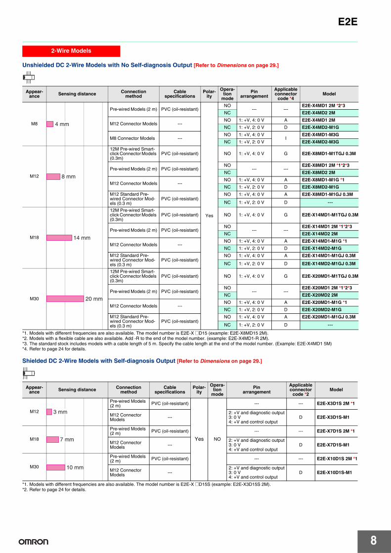
2-Wire Models
Shielded DC 2-wire Models with No Self-diagnostic Output [Refer to Dimensions on page 29.]
Appearance Sensing distance Connection
method Cable
specifications Polar
ity
Operation
mode
Pin arrangement
Applicable connector
code *4 Model
M8
M12 Pre-wired Smart-click Connector Models (0.3m)
PUR (increased oil-resistant)
Yes
NO 1: +V, 4: 0 V H
E2E-X2D1-M1TGJ-U 0.3M
NC 1: +V, 2: 0 V E2E-X2D2-M1TGJ-U 0.3M
PVC (oil-resistant) NO 1: +V, 4: 0 V G E2E-X2D1-M1TGJ 0.3M
Pre-wired Models (2 m)
PUR (increased oil-resistant)
NO
--- ---
E2E-X2D1-U 2M
NC E2E-X2D2-U 2M
PVC (oil-resistant) NO E2E-X2D1-N 2M *2*3
NC E2E-X2D2-N 2M *3
M12 Connector Models ---
NO 1: +V, 4: 0 V A E2E-X2D1-M1G
NC 1: +V, 2: 0 V D E2E-X2D2-M1G
M8 Connector Models ---NO 1: +V, 4: 0 V
I E2E-X2D1-M3G
NC 1: +V, 2: 0 V E2E-X2D2-M3G
M12
M12 Pre-wired Smart-click Connector Models (0.3m)
PUR (increased oil-resistant)
Yes
NO 1: +V, 4: 0 V H
E2E-X3D1-M1TGJ-U 0.3M
NC 1: +V, 2: 0 V E2E-X3D2-M1TGJ-U 0.3M
PVC (oil-resistant) NO 1: +V, 4: 0 V G E2E-X3D1-M1TGJ 0.3M
Pre-wired Models (2 m)
PUR (increased oil-resistant)
NO
--- ---
E2E-X3D1-U 2M
NC E2E-X3D2-U 2M
PVC (oil-resistant) NO E2E-X3D1-N 2M *1*2*3
NC E2E-X3D2-N 2M *3
M12 Connector Models ---
NO 1: +V, 4: 0 V A E2E-X3D1-M1G *1
NC 1: +V, 2: 0 V D E2E-X3D2-M1G
M12 Standard Pre-wired Connector Models (0.3 m) *6
PVC (oil-resistant)
Yes NO 1: +V, 4: 0 V A E2E-X3D1-M1GJ 0.3M
NC 1: +V, 2: 0 V D E2E-X3D2-M1GJ 0.3M
No *5 NO (3, 4): (+V, 0 V) C E2E-X3D1-M1J-T 0.3M
NC (1, 2): (+V, 0 V) D ---
M18
M12 Pre-wired Smart-click Connector Models (0.3m)
PUR (increased oil-resistant)
Yes
NO 1: +V, 4: 0 V H
E2E-X7D1-M1TGJ-U 0.3M
NC 1: +V, 2: 0 V E2E-X7D2-M1TGJ-U 0.3M
PVC (oil-resistant) NO 1: +V, 4: 0 V G E2E-X7D1-M1TGJ 0.3M
Pre-wired Models (2 m)
PUR (increased oil-resistant)
NO
--- ---
E2E-X7D1-U 2M
NC E2E-X7D2-U 2M
PVC (oil-resistant) NO E2E-X7D1-N 2M *1*2*3
NC E2E-X7D2-N 2M *3
M12 Connector Models ---
NO 1: +V, 4: 0 V A E2E-X7D1-M1G *1
NC 1: +V, 2: 0 V D E2E-X7D2-M1G
M12 Standard Pre-wired Connector Models (0.3 m) *6
PVC (oil-resistant)
Yes NO 1: +V, 4: 0 V A E2E-X7D1-M1GJ 0.3M
NC 1: +V, 2: 0 V D E2E-X7D2-M1GJ 0.3M
No *5 NO (3, 4): (+V, 0 V) C E2E-X7D1-M1J-T 0.3M
NC (1, 2): (+V, 0 V) D E2E-X7D2-M1J-T 0.3M
M30
M12 Pre-wired Smart-click Connector Models (0.3m)
PUR (increased oil-resistant)
Yes
NO 1: +V, 4: 0 V H
E2E-X10D1-M1TGJ-U 0.3M
NC 1: +V, 2: 0 V E2E-X10D2-M1TGJ-U 0.3M
PVC (oil-resistant) NO 1: +V, 4: 0 V G E2E-X10D1-M1TGJ 0.3M
Pre-wired Models (2 m)
PUR (increased oil-resistant)
NO
--- ---
E2E-X10D1-U 2M
NC E2E-X10D2-U 2M
PVC (oil-resistant) NO E2E-X10D1-N 2M *1*2*3
NC E2E-X10D2-N 2M
M12 Connector Models ---
NO 1: +V, 4: 0 V A E2E-X10D1-M1G *1
NC 1: +V, 2: 0 V D E2E-X10D2-M1G
M12 Standard Pre-wired Connector Models (0.3 m) *6
PVC (oil-resistant)
Yes NO 1: +V, 4: 0 V A E2E-X10D1-M1GJ 0.3M
NC 1: +V, 2: 0 V D E2E-X10D2-M1GJ 0.3M
No *5 NO (3, 4): (+V, 0 V) C E2E-X10D1-M1J-T 0.3M
NC (1, 2): (+V, 0 V) D E2E-X10D2-M1J-T 0.3M
2 mm
3 mm
7 mm
10 mm
*1. Models with different frequencies are also available. The model number is E2E-X @D15 (example: E2E-X3D15-N 2M).*2. Models with a flexible cable are also available. Add "-R" rather than "-N" to the end of the model number (example: E2E-X2D1-R 2M).*3. The standard stock includes models with a cable length of 5 m. Specify the cable length at the end of the model number. (Example: E2E-X3D1-N 5M)*4. Refer to page 24 for details.*5. The residual voltage for models without polarity is 5 V, so use caution concerning the connection load interface conditions (e.g., PLC ON voltage). Refer to page 28.*6. The standard cable length is 300 mm. Cables with a length of 500 mm and 1 m can also be manufactured.
7
E2E
2-Wire Models
Unshielded DC 2-Wire Models with No Self-diagnosis Output [Refer to Dimensions on page 29.]
Appearance Sensing distance Connection
method Cable
specifications Polar
ity
Operation
mode
Pin arrangement
Applicable connector
code *4 Model
M8
Pre-wired Models (2 m) PVC (oil-resistant)
Yes
NO --- ---
E2E-X4MD1 2M *2*3
NC E2E-X4MD2 2M
M12 Connector Models ---NO 1: +V, 4: 0 V A E2E-X4MD1 2M
NC 1: +V, 2: 0 V D E2E-X4MD2-M1G
M8 Connector Models ---NO 1: +V, 4: 0 V
I E2E-X4MD1-M3G
NC 1: +V, 2: 0 V E2E-X4MD2-M3G
M12
12M Pre-wired Smart-click Connector Models (0.3m)
PVC (oil-resistant) NO 1: +V, 4: 0 V G E2E-X8MD1-M1TGJ 0.3M
Pre-wired Models (2 m) PVC (oil-resistant) NO
--- ---E2E-X8MD1 2M *1*2*3
NC E2E-X8MD2 2M
M12 Connector Models ---NO 1: +V, 4: 0 V A E2E-X8MD1-M1G *1
NC 1: +V, 2: 0 V D E2E-X8MD2-M1G
M12 Standard Pre-wired Connector Models (0.3 m)
PVC (oil-resistant) NO 1: +V, 4: 0 V A E2E-X8MD1-M1GJ 0.3M
NC 1: +V, 2: 0 V D ---
M18
12M Pre-wired Smart-click Connector Models (0.3m)
PVC (oil-resistant) NO 1: +V, 4: 0 V G E2E-X14MD1-M1TGJ 0.3M
Pre-wired Models (2 m) PVC (oil-resistant) NO
--- ---E2E-X14MD1 2M *1*2*3
NC E2E-X14MD2 2M
M12 Connector Models ---NO 1: +V, 4: 0 V A E2E-X14MD1-M1G *1
NC 1: +V, 2: 0 V D E2E-X14MD2-M1G
M12 Standard Pre-wired Connector Models (0.3 m)
PVC (oil-resistant) NO 1: +V, 4: 0 V A E2E-X14MD1-M1GJ 0.3M
NC 1: +V, 2: 0 V D E2E-X14MD2-M1GJ 0.3M
M30
12M Pre-wired Smart-click Connector Models (0.3m)
PVC (oil-resistant) NO 1: +V, 4: 0 V G E2E-X20MD1-M1TGJ 0.3M
Pre-wired Models (2 m) PVC (oil-resistant) NO
--- ---E2E-X20MD1 2M *1*2*3
NC E2E-X20MD2 2M
M12 Connector Models ---NO 1: +V, 4: 0 V A E2E-X20MD1-M1G *1
NC 1: +V, 2: 0 V D E2E-X20MD2-M1G
M12 Standard Pre-wired Connector Models (0.3 m)
PVC (oil-resistant) NO 1: +V, 4: 0 V A E2E-X20MD1-M1GJ 0.3M
NC 1: +V, 2: 0 V D ---
4 mm
8 mm
14 mm
20 mm
*1. Models with different frequencies are also available. The model number is E2E-X @D15 (example: E2E-X8MD15 2M).*2. Models with a flexible cable are also available. Add -R to the end of the model number. (example: E2E-X4MD1-R 2M).*3. The standard stock includes models with a cable length of 5 m. Specify the cable length at the end of the model number. (Example: E2E-X4MD1 5M)*4. Refer to page 24 for details.
Shielded DC 2-Wire Models with Self-diagnosis Output [Refer to Dimensions on page 29.]
Appearance Sensing distance Connection
method Cable
specifications Polar
ity
Operation
mode
Pin arrangement
Applicable connector
code *2 Model
M12
Pre-wired Models (2 m) PVC (oil-resistant)
Yes NO
--- --- E2E-X3D1S 2M *1
M12 Connector Models ---
2: +V and diagnostic output 3: 0 V 4: +V and control output
D E2E-X3D1S-M1
M18
Pre-wired Models (2 m) PVC (oil-resistant) --- --- E2E-X7D1S 2M *1
M12 Connector Models ---
2: +V and diagnostic output 3: 0 V 4: +V and control output
D E2E-X7D1S-M1
M30
Pre-wired Models (2 m) PVC (oil-resistant) --- --- E2E-X10D1S 2M *1
M12 Connector Models ---
2: +V and diagnostic output 3: 0 V 4: +V and control output
D E2E-X10D1S-M1
3 mm
7 mm
10 mm
*1. Models with different frequencies are also available. The model number is E2E-X @D15S (example: E2E-X3D15S 2M). *2. Refer to page 24 for details.
8

E2E
2-Wire Models
Unshielded DC 2-Wire Models with Self-diagnosis Output [Refer to Dimensions on page 29.]
*1. Models with different frequencies are also available. The model number is E2E-X @MD15S (example: E2E-X8MD15S 2M).
Appearance Sensing distance Connection
method Cable
specifications Polar
ity
Operation
mode
Pin arrangement
Applicable connector
code *2 Model
M12
Pre-wired Models (2 m) PVC (oil-resistant)
Yes NO
--- --- E2E-X8MD1S 2M *
M12 Connector Models ---
2: +V and diagnostic output 3: 0 V 4: +V and control output
D E2E-X8MD1S-M1
M18
Pre-wired Models (2 m) PVC (oil-resistant) --- --- E2E-X14MD1S 2M *
M12 Connector Models ---
2: +V and diagnostic output 3: 0 V 4: +V and control output
D E2E-X14MD1S-M1
M30
Pre-wired Models (2 m) PVC (oil-resistant) --- --- E2E-X20MD1S 2M *
M12 Connector Models ---
2: +V and diagnostic output 3: 0 V 4: +V and control output
D E2E-X20MD1S-M1
8 mm
14 mm
20 mm
*2. Refer to page 24 for details.
Connector Pin Assignments of DC 2-Wire Models • The connector pin assignments of each New E2E DC 2-Wire Model
conform to IEC 947-5-2 Table III. (Only DC 2-Wire Models have been changed in comparison to the previous models.)
Cable length Model 500 mm XS2W-D421-BY1
• The following models with conventional connector pin assignments are available as well. (Only NO Models can be used.) Internal Wiring
The cable at the right should also be used if the XW3A-P@45-G11 (Proximity Sensor end) (Wired end)
Connector Junction Box is already being used.
3 4
4 1
Models with conventional connector pin assignments are available as well.
Appearance Model
NO Applicable connector code * NC Applicable connector code *
Shielded
M8 E2E-X2D1-M1 C E2E-X2D2-M1 D
M12 E2E-X3D1-M1 C E2E-X3D2-M1 D
M18 E2E-X7D1-M1 C E2E-X7D2-M1 D
M30 E2E-X10D1-M1 C E2E-X10D2-M1 D
Unshielded
M8 E2E-X4MD1-M1 C E2E-X4MD2-M1 D
M12 E2E-X8MD1-M1 C E2E-X8MD2-M1 D
M18 E2E-X14MD1-M1 C E2E-X14MD2-M1 D
M30 E2E-X20MD1-M1 C E2E-X20MD2-M1 D
Note: Refer to page 24 for details.
9

E2E
2-Wire Models
AC 2-Wire Models Shielded Models [Refer to Dimensions on page 29.]
Appearance Sensing distance Connection
method Cable
specifications Operation
mode Pin
arrangement Applicable connector code *3 Model
M8 Pre-wired Models (2 m) PVC (oil-resistant)
NO --- ---
E2E-X1R5Y1 2M
NC E2E-X1R5Y2 2M
M12
Pre-wired Models (2 m) PVC (oil-resistant)
NO --- ---
E2E-X2Y1 2M *1*2
NC E2E-X2Y2 2M
M12 Connector Models ---
NO (3, 4): (AC, AC) E E2E-X2Y1-M1
NC (1, 2): (AC, AC) F E2E-X2Y2-M1
M18
Pre-wired Models (2 m) PVC (oil-resistant)
NO --- ---
E2E-X5Y1 2M *1*2
NC E2E-X5Y2 2M
M12 Connector Models ---
NO (3, 4): (AC, AC) E E2E-X5Y1-M1
NC (1, 2): (AC, AC) F E2E-X5Y2-M1
M30
Pre-wired Models (2 m) PVC (oil-resistant)
NO --- ---
E2E-X10Y1 2M *1*2
NC E2E-X10Y2 2M
M12 Connector Models ---
NO (3, 4): (AC, AC) E E2E-X10Y1-M1
NC (1, 2): (AC, AC) F E2E-X10Y2-M1
1.5 mm
2 mm
5 mm
10 mm
*1. Models with different frequencies are also available. The model number is E2E-X @Y@5 (example: E2E-X5Y15 2M).*2. The standard stock includes models with a cable length of 5 m. Specify the cable length at the end of the model number. (Example: E2E-X2Y1 5M)*3. Refer to page 24 for details.
Unshielded Models
Appearance Sensing distance Connection
method Cable
specifications Operation
mode Pin
arrangement Applicable connector code *3 Model
M8 Pre-wired Models (2 m) PVC (oil-resistant)
NO --- ---
E2E-X2MY1 2M
NC E2E-X2MY2 2M
M12
Pre-wired Models (2 m) PVC (oil-resistant)
NO --- ---
E2E-X5MY1 2M *1*2
NC E2E-X5MY2 2M
M12 Connector Models ---
NO (3, 4): (AC, AC) E E2E-X5MY1 2M
NC (1, 2): (AC, AC) F E2E-X5MY2-M1
M18
Pre-wired Models (2 m) PVC (oil-resistant)
NO --- ---
E2E-X10MY1 2M *1
NC E2E-X10MY2 2M
M12 Connector Models ---
NO (3, 4): (AC, AC) E E2E-X10MY1-M1
NC (1, 2): (AC, AC) F E2E-X10MY2-M1
M30
Pre-wired Models (2 m) PVC (oil-resistant)
NO --- ---
E2E-X18MY1 2M *1
NC E2E-X18MY2 2M
M12 Connector Models ---
NO (3, 4): (AC, AC) E E2E-X18MY1-M1
NC (1, 2): (AC, AC) F E2E-X18MY2-M1
2 mm
5 mm
10 mm
18 mm
*1. Models with different frequencies are also available. The model number is E2E-X @MY@5 (example: E2E-X5MY15 2M).*2. The standard stock includes models with a cable length of 5 m. Specify the cable length at the end of the model number. (Example: E2E-X5MY1 5M)*3. Refer to page 24 for details.
AC 2-Wire Models Shielded Models [Refer to Dimensions on page 29.] (There are no unshielded models.)
Appearance Sensing distance Connection
method Cable
specifications Operation
mode Pin
arrangement Applicable connector code *3 Model
M12 Pre-wired Models (2 m)
PVC (oil-resistant)
NO
--- --- E2E-X3T1 2M
M18 Pre-wired Models (2 m)
PVC (oil-resistant) --- --- E2E-X7T1 2M *
M30 Pre-wired Models (2 m)
PVC (oil-resistant) --- --- E2E-X10T1 2M
3 mm
7 mm
10 mm
Note: Not compliant with CE. * The standard stock includes models with a cable length of 5 m. Specify the cable length at the end of the model number. (Example: E2E-X7T1 5M)
10

E2E
3-Wire Models
Shielded DC 3-Wire Models [Refer to Dimensions on page 29.]
Appearance Sensing distance Connection
method
Cable specifica
tions
Operation
mode
Pin arrangement
Applicable
connector code
*5
Model
NPN output PNP output
3 dia. Pre-wired Models (2 m)
PVC (oil-resistant)
NO --- ---
E2E-CR6C1 2M E2E-CR6B1 2M
NC E2E-CR6C2 2M E2E-CR6B2 2M
4 dia. Pre-wired Models (2 m)
PVC (oil-resistant)
NO --- ---
E2E-CR8C1 2M *1*2 E2E-CR8B1 2M *2
NC E2E-CR8C2 2M E2E-CR8B2 2M
M5 Pre-wired Models (2 m)
PVC (oil-resistant)
NO --- ---
E2E-X1C1 2M *1*2 E2E-X1B1 2M *2
NC E2E-X1C2 2M E2E-X1B2 2M
5.4 dia. Pre-wired Models (2 m)
PVC (oil-resistant)
NO --- ---
E2E-C1C1 2M *1*2 E2E-C1B1 2M
NC E2E-C1C2 2M E2E-C1B2 2M
M8
Pre-wired Models (2 m)
PVC (oil-resistant) NO
--- ---E2E-X1R5E1 2M *1*2 E2E-X1R5F1 2M *1*2
PVC (oil-resistant) NC E2E-X1R5E2 2M E2E-X1R5F2 2M
M12 Connector Models ---
NO 1: +V, 3: 0 V, 4: Control output B E2E-X1R5E1-M1 E2E-X1R5F1-M1
NC 1: +V, 3: 0 V, 2: Control output D E2E-X1R5E2-M1 E2E-X1R5F2-M1
M8 Connector Models ---
NO 1: +V, 3: 0 V, 4: Control output
I E2E-X1R5E1-M3 E2E-X1R5F1-M3
NC 1: +V, 3: 0 V, 2: Control output E2E-X1R5E2-M3 E2E-X1R5F2-M3
M12
Pre-wired Models (2 m)
PVC (oil-resistant)
NO --- ---
E2E-X2E1 2M *1*2*3*4 E2E-X2F1 2M *1*2*3
NC E2E-X2E2 2M E2E-X2F2 2M
M12 Connector Models ---
NO 1: +V, 3: 0 V, 4: Control output B E2E-X2E1-M1 E2E-X2F1-M1
NC 1: +V, 3: 0 V, 2: Control output D E2E-X2E2-M1 E2E-X2F2-M1
M18
Pre-wired Models (2 m)
PVC (oil-resistant)
NO --- ---
E2E-X5E1 2M *1*2*3*4 E2E-X5F1 2M *1*2*3
NC E2E-X5E2 2M E2E-X5F2 2M
M12 Connector Models ---
NO 1: +V, 3: 0 V, 4: Control output B E2E-X5E1-M1 E2E-X5F1-M1
NC 1: +V, 3: 0 V, 2: Control output D E2E-X5E2-M1 E2E-X5F2-M1
M30
Pre-wired Models (2 m)
PVC (oil-resistant)
NO --- ---
E2E-X10E1 2M *1*2*3*4 E2E-X10F1 2M *2
NC E2E-X10E2 2M E2E-X10F2 2M
M12 Connector Models ---
NO 1: +V, 3: 0 V, 4: Control output B E2E-X10E1-M1 E2E-X10F1-M1
NC 1: +V, 3: 0 V, 2: Control output D E2E-X10E2-M1 E2E-X10F2-M1
0.6 mm
0.8 mm
1 mm
1 mm
1.5 mm
2 mm
5 mm
10 mm
*1. The standard stock includes models with a cable length of 5 m. Specify the cable length at the end of the model number. (Example: E2E-X2E1 5M) *2. Models with a flexible cable are also available. Add -R to the end of the model number. (example: E2E-X5E1-R 2M). *3. Models with different frequencies are also available. The model number is E2E-X@@@5 (example: E2E-X5E15 2M). *4. Models with pre-wired e-CON connectors are also available (cable length: 0.3 m). Add "-ECON 0.3M" to the end of the model number. (Example: E2E-X2E1-ECON
0.3M) *5. Refer to page 24 for details.
11

E2E
3-Wire Models
Unshielded DC 3-Wire Models [Refer to Dimensions on page 29.]
Appearance Sensing distance Connection
method Cable
specifications
Operation
mode
Pin arrangement
Applicable
connector code
*5
Model
NPN output PNP output
M8
Pre-wired Models (2 m)
PVC (oil-resistant)
NO --- ---
E2E-X2ME1 2M *2 E2E-X2MF1 2M *2
NC E2E-X2ME2 2M E2E-X2MF2 2M
M12 Connector Models ---
NO 1: +V, 3: 0 V, 4: Control output B E2E-X2ME1-M1 E2E-X2MF1-M1
NC 1: +V, 3: 0 V, 2: Control output D E2E-X2ME2-M1 E2E-X2MF2-M1
M8 Connector Models ---
NO 1: +V, 3: 0 V, 4: Control output
I E2E-X2ME1-M3 E2E-X2MF1-M3
NC 1: +V, 3: 0 V, 2: Control output E2E-X2ME2-M3 E2E-X2MF2-M3
M12
Pre-wired Models (2 m)
PVC (oil-resistant)
NO --- ---
E2E-X5ME1 2M *1*2*3*4 E2E-X5MF1 2M *2
NC E2E-X5ME2 2M E2E-X5MF2 2M
M12 Connector Models ---
NO 1: +V, 3: 0 V, 4: Control output B E2E-X5ME1-M1 E2E-X5MF1-M1
NC 1: +V, 3: 0 V, 2: Control output D E2E-X5ME2-M1 E2E-X5MF2-M1
M18
Pre-wired Models (2 m)
PVC (oil-resistant)
NO --- ---
E2E-X10ME1 2M *1*2*3*4 E2E-X10MF1 2M *2
NC E2E-X10ME2 2M E2E-X10MF2 2M
M12 Connector Models ---
NO 1: +V, 3: 0 V, 4: Control output B E2E-X10ME1-M1 E2E-X10MF1-M1
NC 1: +V, 3: 0 V, 2: Control output D E2E-X10ME2-M1 E2E-X10MF2-M1
M30
Pre-wired Models (2 m)
PVC (oil-resistant)
NO --- ---
E2E-X18ME1 2M *1*2*3*4 E2E-X18MF1 2M *2
NC E2E-X18ME2 2M E2E-X18MF2 2M
M12 Connector Models ---
NO 1: +V, 3: 0 V, 4: Control output B E2E-X18ME1-M1 E2E-X18MF1-M1
NC 1: +V, 3: 0 V, 2: Control output D E2E-X18ME2-M1 E2E-X18MF2-M1
2 mm
5 mm
10 mm
18 mm
*1. The standard stock includes models with a cable length of 5 m. Specify the cable length at the end of the model number. (Example: E2E-X5ME1 5M) *2. Models with a flexible cable are also available. Add -R to the end of the model number. (example: E2E-X5E1-R 2M). *3. Models with different frequencies are also available. The model number is E2E-X@M@@5 (example: E2E-X5ME15 2M). *4. Models with pre-wired e-CON connectors are also available (cable length: 0.3 m). Add "-ECON 0.3M" to the end of the model number. (Example: E2E-X2E1-ECON
0.3M) *5. Refer to page 24 for details.
12

E2E Ratings and Specifications
E2E-X@D@ DC 2-Wire Models
Size M8 M12 M18 M30
Shielded Shielded Unshielded Shielded Unshielded Shielded Unshielded Shielded Unshielded
Item Model E2E-X2D@ E2E-X4MD@ E2E-X3D@ E2E-X8MD@ E2E-X7D@ E2E-X14MD@ E2E-X10D@ E2E-X20MD@
Sensing distance 2 mm ±10% 4 mm ±10% 3 mm ±10% 8 mm ±10% 7 mm ±10% 14 mm ±10% 10 mm ±10% 20 mm ±10%
Set distance *1 0 to 1.6 mm 0 to 3.2 mm 0 to 2.4 mm 0 to 6.4 mm 0 to 5.6 mm 0 to 11.2 mm 0 to 8 mm 0 to 16 mm
Differential travel 15% max. of sensing distance 10% max. of sensing distance
Detectable object Ferrous metal (The sensing distance decreases with non-ferrous metal. Refer to Engineering Data on pages 18 and 19.
Standard sensing object
Iron, 8 × 8 × 1 mm
Iron, 20 × 20 × 1 mm
Iron, 12 × 12 × 1 mm
Iron, 30 × 30 × 1 mm
Iron, 18 × 18 × 1 mm Iron, 30 × 30 × 1 mm Iron,
54 × 54 × 1 mm
Response frequency *2 1.5 kHz 1 kHz 0.8 kHz 0.5 kHz 0.4 kHz 0.1 kHz
Power supply voltage (operating voltage range)
12 to 24 VDC (10 to 30 VDC), ripple (p-p): 10% max.
Leakage current 0.8 mA max.
Control output
Load current 3 to 100 mA, Diagnostic output: 50 mA for -D1(5)S Models
Residual voltage *3
3 V max. (Load current: 100 mA, Cable length: 2 m, M1J-T Models only: 5 V max.)
Indicators D1 Models: Operation indicator (red) and setting indicator (green) D2 Models: Operation indicator (red)
Operation mode (with sensing object approaching)
D1 Models: NO D2 Models: NC
Refer to the timing charts under I/O Circuit Diagrams on page 21 for details.
Diagnostic output delay 0.3 to 1 s
Protection circuits Surge suppressor, Load short-circuit protection (for control and diagnostic output)
Ambient temperature range Operating: −25 to 70°C, Storage: −40 to 85°C (with no icing or condensation)
Ambient humidity range Operating/storage: 35% to 95% (with no condensation)
Temperature influence
±15% max. of sensing distance at 23°C in the temperature range of −25 to 70°C
±10% max. of sensing distance at 23°C in the temperature range of −25 to 70°C
Voltage influence ±1% max. of sensing distance at rated voltage in the rated voltage ±15% range
Insulation resistance 50 MΩ min. (at 500 VDC) between current-carrying parts and case
Dielectric strength 1000 VAC, 50/60 Hz for 1 minute between current carry parts and case
Vibration resistance Destruction: 10 to 55 Hz, 1.5-mm double amplitude for 2 hours each in X, Y, and Z directions
Shock resistance Destruction: 500 m/s2
10 times each in X, Y, and Z directions
Destruction: 1,000 m/s2 10 times each in X, Y, and Z directions
Degree of protection Pre-wired Models: IEC 60529 IP67, in-house standards: oil-resistant Connector Models: IEC 60529 IP67
Connection method Pre-wired Models (Standard cable length: 2 m), Connector Models, or Pre-wired Connector Models (Standard cable length: 0.3 m)
Weight (packed state)
Pre-wired Models Approx. 60 g Approx. 70 g Approx. 130 g Approx. 175 g
Pre-wired Connector Models
--- Approx. 40 g Approx. 70 g Approx. 110 g
Connector Models Approx. 15 g Approx. 25 g Approx. 40 g Approx. 90 g
Materials
Case Stainless steel (SUS303) Nickel-plated brass
Sensing surface PBT
Clamping nuts Nickel-plated brass
Toothed washer Zinc-plated iron
Accessories Instruction manual
*1. Use the E2E within the range in which the setting indicator (green LED) is ON (except D2 Models). *2. The response frequency is an average value.
Measurement conditions are as follows: standard sensing object, a distance of twice the standard sensing object, and a set distance of half the sensing distance. *3. The residual voltage of each M1J-T Model is 5 V. When connecting to a device, make sure that the device can withstand the residual voltage. (Refer to page 28 for
details.)
13

E2E
E2E-X@Y@ AC 2-Wire Models
Size M8 M12 M18 M30
Shielded Shielded Unshielded Shielded Unshielded Shielded Unshielded Shielded Unshielded
Item Model E2E-X1R5Y@ E2E-X2MY@ E2E-X2Y@ E2E-X5MY@ E2E-X5Y@ E2E-X10MY@ E2E-X10Y@ E2E-X18MY@
Sensing distance 1.5 mm ±10% 2 mm ±10% 5 mm ±10% 10 mm ±10% 18 mm ±10%
Set distance 0 to 1.2 mm 0 to 1.6 mm 0 to 4 mm 0 to 8 mm 0 to 14 mm
Differential travel 10% max. of sensing distance
Detectable object Ferrous metal (The sensing distance decreases with non-ferrous metal. Refer to Engineering Data on page 19.)
Standard sensing object
Iron, 8 × 8 × 1 mm Iron, 12 × 12 × 1 mm Iron,
15 × 15 × 1 mm Iron, 18 × 18 × 1 mm Iron, 30 × 30 × 1 mm Iron,
54 × 54 × 1 mm
Response frequency 25 Hz
Power supply voltage (operating voltage range)*1
24 to 240 VAC (20 to 264 VAC), 50/60 Hz
Leakage current 1.7 mA max.
Control output
Load current *2 5 to 100 mA 5 to 200 mA 5 to 300 mA
Residual voltage Refer to Engineering Data on page 20.
Indicators Operation indicator (red)
Operation mode (with sensing object approaching)
Y1 Models: NO Y2 Models: NC
Refer to the timing charts under I/O Circuit Diagrams on page 23 for details.
Protection circuits Surge suppressor
Ambient temperature range *1*2
Operating/Storage: −25 to 70°C (with no icing or condensation) Operating/Storage: −40 to 85°C (with no icing or condensation)
Ambient humidity range Operating/storage: 35% to 95% (with no condensation)
Temperature influence
±10% max. of sensing distance at 23°C in the temperature range of −25 to 70°C
±15% max. of sensing distance at 23°C in the temperature range of −40 to 85°C, ±10% max. of sensing distance at 23°C in the temperature range of −25 to 70°C
Voltage influence ±1% max. of sensing distance at rated voltage in the rated voltage ±15% range
Insulation resistance 50 MΩ min. (at 500 VDC) between current-carrying parts and case
Dielectric strength 4,000 VAC (M8 Models: 2,000 VAC), 50/60 Hz for 1 min between current-carrying parts and case
Vibration resistance Destruction: 10 to 55 Hz, 1.5-mm double amplitude for 2 hours each in X, Y, and Z directions
Shock resistance Destruction: 500 m/s2
10 times each in X, Y, and Z directions
Destruction: 1,000 m/s2 10 times each in X, Y, and Z directions
Degree of protection Pre-wired Models: IEC 60529 IP67, in-house standards: oil-resistant Connector Models: IEC 60529 IP67
Connection method Pre-wired Models (Standard cable length: 2 m) and Connector Models
Weight
Pre-wired Models Model
Approx. 60 g Approx. 70 g Approx. 130 g Approx. 175 g
Connector Models
Approx. 15 g Approx. 25 g Approx. 40 g Approx. 90 g
Materials
Case Stainless steel (SUS303) Nickel-plated brass
Sensing surface PBT
Clamping nuts Nickel-plated brass
Toothed washer Zinc-plated iron
Accessories Instruction manual
*1. When supplying 24 VAC to any of the above models, make sure that the operating ambient temperature range is at least −25°C. *2. When using an M18 or M30 Connector Model at an ambient temperature between 70 and 85°C, make sure that the Sensor has a control output (load current) of
5 to 200 mA max.
14

E2E
E2E-X@T1 AC/DC 2-Wire Models
Size M12 M18 M30
Shielded Shielded
Item Model E2E-X3T1 E2E-X7T1 E2E-X10T1
Sensing distance 3 mm ±10% 7 mm ±10% 10 mm ±10%
Set distance 0 to 2.4 mm 0 to 5.6 mm 0 to 8 mm
Differential travel 10% max. of sensing distance
Detectable object Ferrous metal (The sensing distance decreases with non-ferrous metal. Refer to Engineering Data on page 18.)
Standard sensing object Iron, 12 × 12 × 1 mm Iron, 18 × 18 × 1 mm Iron, 30 × 30 × 1 mm
Response frequency *1
DC 1 kHz 0.5 kHz 0.4 kHz
AC 25 Hz
Power supply voltage (operating voltage range) *2
24 to 240 VDC (20 to 264 VDC) 48 to 240 VAC (40 to 264 VAC)
Leakage current DC: 1 mA max. AC: 2 mA max.
Control output
Load current 5 to 100 mA
Residual voltage
DC: 6 V max. (Load current: 100 mA, Cable length: 2 m) AC: 10 V max. (Load current: 5 mA, Cable length: 2 m)
Indicators Operation indicator (red), Setting indicator (green)
Operation mode (with sensing object approaching)
NO (Refer to the timing charts under I/O Circuit Diagrams on page 21 for details.)
Protection circuits Load short-circuit protection (20 to 40 VDC only), Surge suppressor
Ambient temperature range Operating: −25 to 70°C, Storage: −40 to 85°C (with no icing or condensation)
Ambient humidity range Operating/Storage: 35% to 95% (with no condensation)
Temperature influence ±10% max. of sensing distance at 23°C in the temperature range of −25 to 70°C
Voltage influence ±1% max. of sensing distance at rated voltage in the rated voltage ±15% range
Insulation resistance 50 MΩ min. (at 500 VDC) between current-carrying parts and case
Dielectric strength 4,000 VAC, 50/60 Hz for 1 minute between current-carrying parts and case
Vibration resistance Destruction: 10 to 55 Hz, 1.5-mm double amplitude for 2 hours each in X, Y, and Z directions
Shock resistance Destruction: 1,000 m/s2 10 times each in X, Y, and Z directions
Degree of protection IEC 60529 IP67, in-house standards: oil-resistant
Connection method Pre-wired Models (Standard cable length: 2 m)
Weight (packed state) Approx. 80 g Approx. 140 g Approx. 190 g
Materials
Case Nickel-plated brass
Sensing surface PBT
Clamping nuts Nickel-plated brass
Toothed washer Zinc-plated iron
Accessories Instruction manual
*1. The response frequency is an average value. Measurement conditions are as follows: standard sensing object, a distance of twice the standard sensing object, and a set distance of half the sensing distance.
*2. Power Supply Voltage Waveform: Use a sine wave for the power supply. Using a rectangular AC power supply may result in faulty reset.
15
E2E
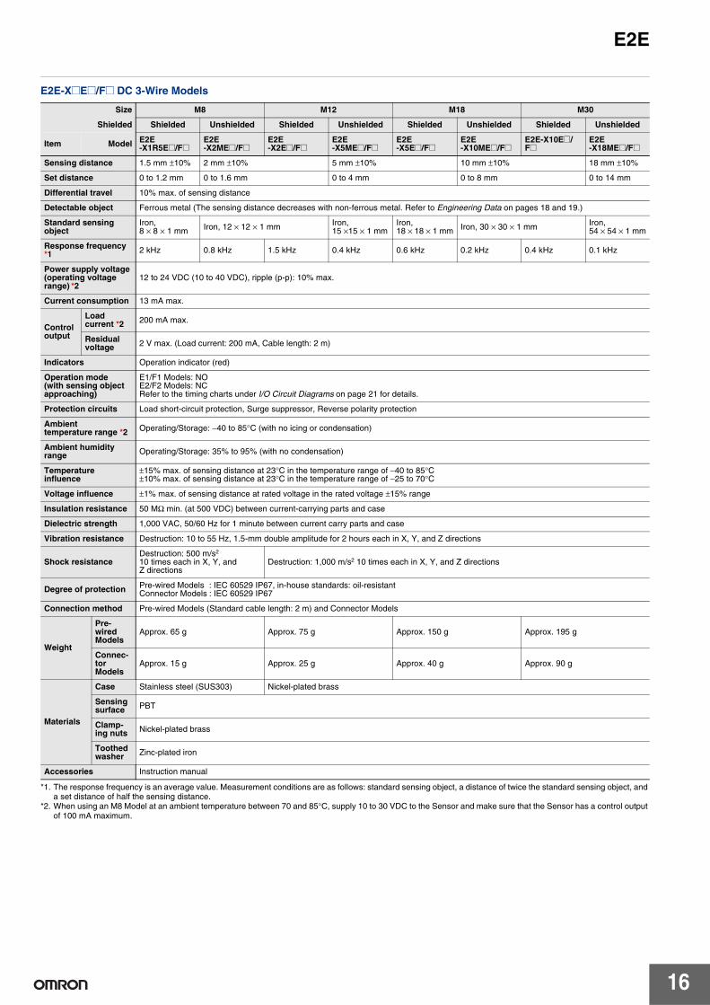
E2E-X@E@/F@ DC 3-Wire Models
Size M8 M12 M18 M30
Shielded Shielded Unshielded Shielded Unshielded Shielded Unshielded Shielded Unshielded
Item Model E2E -X1R5E@/F@
E2E -X2ME@/F@
E2E -X2E@/F@
E2E -X5ME@/F@
E2E -X5E@/F@
E2E -X10ME@/F@
E2E-X10E@/ F@
E2E -X18ME@/F@
Sensing distance 1.5 mm ±10% 2 mm ±10% 5 mm ±10% 10 mm ±10% 18 mm ±10%
Set distance 0 to 1.2 mm 0 to 1.6 mm 0 to 4 mm 0 to 8 mm 0 to 14 mm
Differential travel 10% max. of sensing distance
Detectable object Ferrous metal (The sensing distance decreases with non-ferrous metal. Refer to Engineering Data on pages 18 and 19.)
Standard sensing object
Iron, 8 × 8 × 1 mm Iron, 12 × 12 × 1 mm Iron,
15 ×15 × 1 mm Iron, 18 × 18 × 1 mm Iron, 30 × 30 × 1 mm Iron,
54 × 54 × 1 mm
Response frequency *1 2 kHz 0.8 kHz 1.5 kHz 0.4 kHz 0.6 kHz 0.2 kHz 0.4 kHz 0.1 kHz
Power supply voltage (operating voltage range) *2
12 to 24 VDC (10 to 40 VDC), ripple (p-p): 10% max.
Current consumption 13 mA max.
Control output
Load current *2 200 mA max.
Residual voltage 2 V max. (Load current: 200 mA, Cable length: 2 m)
Indicators Operation indicator (red)
Operation mode (with sensing object approaching)
E1/F1 Models: NO E2/F2 Models: NC Refer to the timing charts under I/O Circuit Diagrams on page 21 for details.
Protection circuits Load short-circuit protection, Surge suppressor, Reverse polarity protection
Ambient temperature range *2 Operating/Storage: −40 to 85°C (with no icing or condensation)
Ambient humidity range Operating/Storage: 35% to 95% (with no condensation)
Temperature influence
±15% max. of sensing distance at 23°C in the temperature range of −40 to 85°C ±10% max. of sensing distance at 23°C in the temperature range of −25 to 70°C
Voltage influence ±1% max. of sensing distance at rated voltage in the rated voltage ±15% range
Insulation resistance 50 MΩ min. (at 500 VDC) between current-carrying parts and case
Dielectric strength 1,000 VAC, 50/60 Hz for 1 minute between current carry parts and case
Vibration resistance Destruction: 10 to 55 Hz, 1.5-mm double amplitude for 2 hours each in X, Y, and Z directions
Shock resistance Destruction: 500 m/s2
10 times each in X, Y, and Z directions
Destruction: 1,000 m/s2 10 times each in X, Y, and Z directions
Degree of protection Pre-wired Models : IEC 60529 IP67, in-house standards: oil-resistant Connector Models : IEC 60529 IP67
Connection method Pre-wired Models (Standard cable length: 2 m) and Connector Models
Weight
Pre-wired Models
Approx. 65 g Approx. 75 g Approx. 150 g Approx. 195 g
Connector Models
Approx. 15 g Approx. 25 g Approx. 40 g Approx. 90 g
Materials
Case Stainless steel (SUS303) Nickel-plated brass
Sensing surface PBT
Clamping nuts Nickel-plated brass
Toothed washer Zinc-plated iron
Accessories Instruction manual
*1. The response frequency is an average value. Measurement conditions are as follows: standard sensing object, a distance of twice the standard sensing object, and a set distance of half the sensing distance.
*2. When using an M8 Model at an ambient temperature between 70 and 85°C, supply 10 to 30 VDC to the Sensor and make sure that the Sensor has a control output of 100 mA maximum.
16

E2E
E2E-C@C/B@ and E2E-X1C/B@ DC 3-Wire Models
Size 3 dia. 4 dia. M5 5.4 dia.
Shielded Shielded
Item Model E2E-CR6C/B@ E2E-CR8C/B@ E2E-X1C/B@ E2E-C1C/B@
Sensing distance 0.6 mm ±15% 0.8 mm ±15% 1 mm ±15%
Set distance 0 to 0.4 mm 0 to 0.5 mm 0 to 0.7 mm
Differential travel 15% max. of sensing distance
Detectable object Ferrous metal (The sensing distance decreases with non-ferrous metal. Refer to Engineering Data on pages 18 and 19.)
Standard sensing object Iron, 3 × 3 × 1 mm Iron, 5 × 5 × 1 mm
Response frequency * 2 kHz 3 kHz
Power supply voltage (operating voltage range)
12 to 24 VDC (10 to 30 VDC), ripple (p-p): 10% max.
Current consumption 10 mA max. 17 mA max.
Control output
Load current
Open-collector output, 80 mA max. (30 VDC max.) Open-collector output, 100 mA max. (30 VDC max.)
Residual voltage
1 V max. (Load current: 80 mA, Cable length: 2 m)
2 V max. (Load current: 100 mA, Cable length: 2 m)
Indicators Operation indicator (red)
Operation mode (with sensing object approaching)
C1/B1 Models: NO C2 Models: NC Refer to the timing charts under I/O Circuit Diagrams on page 22 for details.
Protection circuits Reverse polarity protection, Surge suppressor
Ambient temperature range Operating/Storage: −25 to 70°C (with no icing or condensation)
Ambient humidity range Operating/Storage: 35% to 95% (with no condensation)
Temperature influence ±15% max. of sensing distance at 23°C in the temperature range of −25 to 70°C
Voltage influence ±5% max. of sensing distance at rated voltage in the rated voltage ±10% range
±2.5% max. of sensing distance at rated voltage in the rated voltage ±15% range
Insulation resistance 50 MΩ min. (at 500 VDC) between current-carrying parts and case
Dielectric strength 500 VAC, 50/60 Hz for 1 min between current-carrying parts and case
Vibration resistance Destruction: 10 to 55 Hz, 1.5-mm double amplitude for 2 hours each in X, Y, and Z directions
Shock resistance Destruction: 500 m/s2 10 times each in X, Y, and Z directions
Degree of protection IEC 60529 IP66 IEC 60529 IP67, in-house standards: oil-resistant
Connection method Pre-wired Models (Standard cable length: 2 m)
Weight (packed state) Approx. 60 g
Materials
Case Stainless steel (SUS303) Nickel-plated brass
Sensing surface Heat-resistant ABS
Clamping nuts Nickel-plated brass (E2E-X1C/B@ only)
Toothed washer Zinc-plated iron (E2E-X1C/B@ only)
Accessories Instruction manual
* The response frequency is an average value. Measurement conditions are as follows: standard sensing object, a distance of twice the standard sensing object, and a set distance of half the sensing distance.
17

12
10
8
6
4
2
15
10
5
1.5
1.0
0.5
E2E Engineering Data (Typical)
Sensing Area
Shielded Models E2E-C@C@/-X@C@
E2E-X@D@/-X@T1 E2E-C@B1/-X@B@E2E-X@E@/-X@Y@/-X@F@
12
Dis
tanc
e X
(m
m)
10
8 Dis
tanc
e X
(m
m)
E2E-X1/E2E-C1
E2E-CR8
E2E-CR6
X Y
−3.0 −2.0 −1.0 0 1.0 2.0
1.6
1.4
1.2
1.0
0.8
0.6
0.4
0.2
0
Distance Y (mm)
E2E-X10
E2E -X1R5
E2E-X5
E2E-X2
X Y
Dis
tanc
e X
(m
m)
X Y
E2E-X10
E2E-X7
E2E-X3
E2E-X2
6
4
2
0 −20 −15 −10 −5 0 5 10 15 −15 −10 −5 0 5 10
Distance Y (mm) Distance Y (mm)
0
Unshielded Models
E2E-X@MD@ E2E-X@ME@/-X@MY@/-X@MF@
Dis
tanc
e X
(m
m)
E2E-X18M
E2E-X10M
E2E-X5M
E2E-X2M
X Y
−30 −20 −10 0 10 20
30
25
20
15
10
5
0
Distance Y (mm)
Dis
tanc
e X
(m
m) 30
25
20
X Y
E2E -X20M
E2E -X14M
E2E -X8M
E2E -X4M
0 −30 −20 −10 0 10 20
Distance Y (mm)
Influence of Sensing Object Size and Material
E2E-X2D@ E2E-X3D@/-X3T1 E2E-X7D@/-X7T1
d × d
X t = 1 mm
Iron
Staste(SU
inless el S304)
Bra
AluCo
ss
minum pper
Dis
tanc
e X
(m
m)
Dis
tanc
e X
(m
m) 3.0
2.5
2.0 Dis
tanc
e X
(m
m) 8
7
6
4.0
3.5
3.0
d × d t = 1 mm
IronX
Ss
tainless teel
(SUS304) Brass
Aluminum
Copper
d × d
X t = 1 mm
Iron
Stainless steel (SUS304)
Brass
Aluminum Copper
52.5
4
3
2
2.0
1.5
1.0
10.5
0 5 10 15 20 25 0 5 10 15 20 25 30 35 40 0 10 20 30 40 50 Side length of sensing object: d (mm) Side length of sensing object: d (mm) Side length of sensing object: d (mm)
E2E-X10D@/-X10T1 E2E-X4MD@ E2E-X8MD@
X
d × d
t = 1 mm Iron
Stainless steel (SUS3
Brass
04)
AluminCoppe
um r
Dis
tanc
e X
(m
m) 6
5
4
3
2
X
d × d t = 1 mm
Iron
Stainlesteel (SUS3
ss
04)
Brass
Copper Aluminum
Dis
tanc
e X
(m
m)
12
10
8
6
4
d × d
X t = 1 mm
Iron
Stainless steel (SUS304)
Brass
Aluminum Copper
Dis
tanc
e X
(m
m) 12
1 2
0 10 20 30 40 50 60 70 0 10 20 30 40 50 60 70 0 10 15 20 30 40 50 60 70 Side length of sensing object: d (mm) Side length of sensing object: d (mm) Side length of sensing object: d (mm)
18
10
8
6
4
2

E2E
E2E-X14MD@ E2E-X20MD@ E2E-X1R5E@/-X1R5Y@/-X1R5F@
25 25 2.5
20 20 2.0
Dis
tanc
e X
(m
m)
Dis
tanc
e X
(m
m)
15
10
5
X
d × d
t = 1 mm
Iron
Stainless steel (SUS304) Brass Aluminum Copper
Dis
tanc
e X
(m
m)
X
d × d t = 1 mm
Iron
Stainless steel (SUS304)
Brass Aluminum Copper
d × d
X t = 1 mm
Iron
Stainless steel (SUS304)
Brass
Aluminum
1.515
10 1.0
0.55
0 10 20 30 40 50 60 70 0 10 20 30 40 50 60 70 80 90 100 0 5 10 15 20 25
Side length of sensing object: d (mm) Side length of sensing object: d (mm) Side length of sensing object: d (mm)
E2E-X2E@/-X2Y@/-X2F@ E2E-X5E@/-X5Y@/-X5F@ E2E-X10E@/-X10Y@/-X10F@
Dis
tanc
e X
(m
m)
Dis
tanc
e X
(m
m) 7 12
Dis
tanc
e X
(m
m)
21
X
d × d t = 1 mm
Stainless steel (SUS304)
Iron
Brass
Aluminum
0 10 20 30 40 50 0 10 20 30 40 50 60
d × d
X t = 1 mm
Stainless steel (SUS304)
Iron
Brass
Aluminum
2.5
2.0
d × d
X t = 1 mm
Iron
Stainless steel (SUS304)
Brass
Aluminum
6 10
5 8
1.5 4
6
3 1.0
4 2
0.5
0 5 10 15 20 25
Side length of sensing object: d (mm) Side length of sensing object: d (mm) Side length of sensing object: d (mm)
E2E-X2ME@/-X2MY@/-X2MF@ E2E-X5ME@/-X5MY@/-X5MF@ E2E-X10ME@/-X10MY@/-X10MF@
Dis
tanc
e X
(m
m) 12
X
Stainless steel (SUS304)
Iron
Brass
Aluminum
d × d t = 1 mm
Dis
tanc
e X
(m
m) 7
X
d × d t = 1 mm
Stainless steel (SUS304)
Iron
Brass
Aluminum
6
3
1.5
X
d × d t = 1 mm
Iron
Stainless steel (SUS304)
Brass
Aluminum
Copper
4
2.5
Dis
tanc
e X
(m
m)
6 10 2.0
5 8
1.0 4
2
0.5 2 1
0 5 10 15 20 25 30 0 10 20 30 40 50 0 10 20 30 40 50 60
Side length of sensing object: d (mm) Side length of sensing object: d (mm) Side length of sensing object: d (mm)
E2E-X18ME@/-X18MY@/-X18MF@ E2E-CR6@ E2E-CR8@
X
d × d t = 1 mm
Stainless steel (SUS304)
Iron
Brass
Aluminum
0 5 10 15 20 25 30
1.2
1.0
0.8
0.6
0.4
0.2
X
d × d t = 1 mm
Stainless steel (SUS304)
Iron
Brass
Aluminum Copper
Dis
tanc
e X
(m
m)
Dis
tanc
e X
(m
m) 25
20
d × d
X t = 1 mm
Stainless steel (SUS304)
Iron
Brass
Aluminum
Dis
tanc
e X
(m
m) 0.7
0.6
0.5
15 0.4
0.310
0.2
5
0.1
0 20 40 60 80 100 0 5 10 15 20
Side length of sensing object: d (mm) Side length of sensing object: d (mm) Side length of sensing object: d (mm)
19

0.4
0.2
5
4
3
30
E2E
E2E-X1@/-C1@ 1.2
1.0
0.8
0.6
0.4
0.2
X
d × d t = 1 mm
Stainless steel (SUS304)
Iron
Brass
Aluminum
Dis
tanc
e X
(m
m)
0 5 10 15 20 25 Side length of sensing object: d (mm)
Leakage Current
E2E-X@D@ E2E-X@Y@ E2E-X@T1
Leak
age
curr
ent (
mA
) 1.4
1.2
1.0
0.8
E2E-X10D1-N
E2EX3D1-N
E2E-X2D1-N
E2E-X7D1-N
1.0
0.8
0.6
V
~mA
~ AC power
Protective resistance
Proximity Sensor (OFF)
AC power
DC power
Leak
age
curr
ent (
mA
) 1.4
1.2
1.0
0.8Leak
age
curr
ent (
mA
)
0.6 0.6
0.4 0.4
0.20.2
0 5 10 15 20 25 30 0 50 100 150 200 250 300 0 50 100 150 200 250 300 Power supply voltage (V) Power supply voltage (V) Power supply voltage (V)
Residual Output Voltage
E2E-X@D@ E2E-X@T1
2 E2E-X@D@
E2E-X@D1-M1J-T
3
1 2
0
24 VDC
100 VAC
200 VAC 6
Res
idua
l out
put v
olta
ge (
V)
Res
idua
l out
put v
olta
ge (
V)
5
4
1 3 5 10 30 50 100 1 3 5 10 30 50 100 Load current (mA) Load current (mA)
E2E-X@Y@ at 24 VAC E2E-X@Y@ at 100 VAC E2E-X@Y@ at 200 VAC
Load
vol
tage
VL
(V)
Load
vol
tage
VL
(V)
V
120
100
80
40
100 VAC VL
~
~A
OFF
ON
Residual output voltage
Residual load voltage
80
V
25
20
15
5
01 3 5 10 30 50 100 300 500
VL
~
~A 24 VAC
OFF
ON
Load current (mA)
Residual load voltage
Residual output voltage
60
20
01 3 5 10 30 50 100 300 500
Load current (mA)
120
40
01 3 5 10 30 50 100 300 500
Load current (mA)
240
Load
vol
tage
VL
(V)
200
V
200 VAC VL
~A
~
Residual output voltage
ON
160
Residual load voltage
OFF
20
10

E2E I/O Circuit Diagrams
E2E-X@D@ DC 2-Wire Models Operation
mode Model Timing Chart Output circuit
Without self
E2E-X@D1-N E2E-X@D1-M1G(J) E2E-X@D1-(M1TGJ)-U E2E-X@D1-M3G
(%) 80 0100
Sensing object
Rated sensing distance
Stable sensing area Non-sensing
area
Unstable sensing area
Set position
Proximity Sensor
ON
OFF
ON
OFF
ON
OFF
Setting indicator (green)
Operation indicator (red)
Control output
0 V
+V
4
1 Load
Brown
Blue
Polarity: Yes
Note: The load can be connected to either the +V or 0 V side.
Proximity Sensor main circuit
0 V (+V)
+V (0 V)
3
4 Load
Proximity Sensor main circuit
Polarity: None
Note 1. The load can be connected to either the +V or 0 V side.
2. The E2E-X@D1-M1J-T has no polarity. Therefore, terminals 3 and 4 have no polarity.
diagnostic output:
NO
E2E-X@D1-M1J-T
Without self-
diagnostic output:
NC
E2E-X@D2-N E2E-X@D2-M1G E2E-X@D2-(M1TGJ)-U E2E-X@D2-M3G
0(%) 100
Sensing object
Rated sensing distance
Sensing area Non-sensing
area
Proximity Sensor
ON
OFF
ON
OFF
Operation indicator (red)
Control output
0 V
+V
2
1 Load
Brown
Blue
Note: The load can be connected to either the +V or 0 V side.
Proximity Sensor main circuit
With self-diagnostic
output: NO
E2E-X@D1S E2E-X@D1S-M1
(%) 80 0100
Sensing object
Rated sensing distance
Stable sensing area Non-sensing
area
Unstable sensing area
Set position
Proximity Sensor
ON
OFF
ON
OFF
ON
OFF
ON
OFF
Setting indicator (green)
Operation indicator (red)
Control output
Diagnostic output*
* The diagnostic output is ON when there is a coil burnout or the sensing object is located in the unstable sensing area for 0.3 s or longer.
+V
+V
0
Load
Load
Brown (4)
Orange (2) (diagnostic output)
Blue (3)
Note: Connect both the loads to the +V side of the control output and diagnostic output.
Proximity Sensor main circuit
21

E2E
DC 3-Wire Models
Operation mode
Output specifica
tions Model Timing Chart Output circuit
NO
NPN output E2E-X@E@ E2E-X@E@-M1
Present
Not present
ON
OFF
ON
OFF
High
Low
Operation indicator (red)
Sensing object
Control output (between brown and black leads)
Output voltage (between black and blue leads)
+V
Tr
0 V
100 Ω
3
4
1
Load
Brown
Black
*Constant current output is 1.5 to 3 mA. Blue
Constant current*
Proximity Sensor
main circuit
Note: For Connector Models, the connection between pins 1, 4 and 3 uses an NO contact, and the connection between pins 1, 2 and 3 uses an NC contact.
2
NC
E2E-X@E@-M3 Present
Not present
ON
OFF
ON
OFF
High
Low
Operation indicator (red)
Sensing object
Control output (between brown and black leads)
Output voltage (between black and blue leads)
NO
PNP output E2E-X@F@ E2E-X@F@-M1 E2E-X@F@-M3
Present
Not present
ON
OFF
ON
OFF
High
Low
Operation indicator (red)
Sensing object
Control output (Between blue and black leads)
Output voltage (between brown and black leads)
Present
Not present
ON
OFF
ON
OFF
High
Low
Operation indicator (red)
Sensing object
Control output (Between blue and black leads)
Output voltage (between brown and black leads)
100 Ω
Tr
+V
*
Load
Brown
Black
*When a transistor is connected
Blue
Proximity Sensor
main circuit
Note: For Connector Models, the connection between pins 1, 4 and 3 uses an NO contact, and the connection between pins 1, 2 and 3 uses an NC contact.
0 V
3
4
1
2
NC
NO
NPN open-collector
Present
Not present
ON
OFF
ON
OFF
Operation indicator (red)
Sensing object
Control output
+V 100 Ω *
0 V
Load
Brown
Black
Blue
Proximity Sensor
main circuit
*The E2E-CR6@ does not have 100-Ω resistance.
NC
output E2E-C/X@C@
Present
Not present
ON
OFF
ON
OFF
Operation indicator (red)
Sensing object
Control output
NO
PNP open-collector E2E-C/X@B@
Present
Not present
ON
OFF
ON
OFF
Operation indicator (red)
Sensing object
Control output
0 V
+V
100 Ω *
Load
Brown
Black
Blue
Proximity Sensor
main circuit
*The E2E-CR6@ does not have 100-Ω resistance.
NC
output Present
Not present
ON
OFF
ON
OFF
Operation indicator (red)
Sensing object
Control output
22

E2E
AC 2-Wire Models
Operation mode Model Timing Chart Output circuit
NO
E2E-X@Y@ E2E-X@Y@-M1
NC
Present
Not present
ON
OFF
Operate
Reset
Operation indicator (red)
Sensing object
Control output
Load
Brown 3 (or 1)
Blue 4 (or 2)
Proximity Sensor
main circuit
Note: For Connector Models, the connection between pins 3 and 4 uses an NO contact, and the connection between pins 1 and 2 uses an NC contact.
Present
Not present
ON
OFF
Operate
Reset
Operation indicator (red)
Sensing object
Control output
AC/DC 2-Wire Models
Operation mode Model Timing Chart Output circuit
NO E2E-X@T1 80100 0(%)
Sensing object
Rated sensing distance
Stable sensing area Non-sensing
area
Unstable sensing area
Set position
Proximity Sensor
ON
OFF
ON
OFF
ON
OFF
Setting indicator (green)
Operation indicator (red)
Control output
24 to 240 VDC
48 to 240 VAC
Load Brown
Blue
Proximity Sensor
main circuit
Power supply
Note: The load can be connected to either the +V or 0 V side. There is no need to be concerned about the polarity (brown/blue) of the Proximity Sensor.
e-CON Connectors Requirement for e-CON Pre-wired Connector: A Connector is not provided with the Sensor. Be sure to order a Connector separately. [Dimensions: Inquire.]
Appearance Cable length Connector model number Applicable Proximity Sensor model number
2 m E39-ECON2M
E2E-X@E@-ECON 5 m E39-ECON5M
0.5 to 1 m E39-ECONW@M @ indicates cable length (in units of m). Specify with 0.1-increments.
1.1 to 1.5 m
1.6 to 2 m
12
34
Single-end connector
12
34
43
12
Double-end connectors
23

E2E Sensor I/O Connectors Model for Connectors and Pre-wired Connectors: A Connector is not provided with the Sensor. Be sure to order a Connector separately. [Refer to Dimensions for the XS2, XS3, and XS5.]
Applicable connector
Connector Applicable Proximity
Sensor model number
Connection diagram No. *2
Cable length 2m Cable length 5m
code Screw Appearance *1 CablConnector CablConnector model number model number
A Straight XS2F-D421-DA0-A XS2F-D421-GA0-A
E2E-X@D1-M1G(J) 1 L-shape XS2F-D422-DA0-A XS2F-D422-GA0-A
B Straight XS2F-D421-DC0-A XS2F-D421-GC0-A E2E-X@E1-M1
E2E-X@F1-M1 10 L-shape XS2F-D422-DC0-A XS2F-D422-GC0-A
XS2F-D421-DD0 XS2F-D421-GD0 E2E-X@D1-M1J-T 3
C Straight
E2E-X@D1-M1 2
L-shape XS2F-D422-DD0 XS2F-D422-GD0 E2E-X@D1-M1J-T 3 E2E-X@D1-M1 2 E2E-X@D2-M1G(J) 6 E2E-X@D2-M1J-T 8
Straight XS2F-D421-D80-A XS2F-D421-G80-A E2E-X@D2-M1 7 E2E-X@D1S-M1 5
D M12
E2E-X@E2-M1 E2E-X@F2-M1 11
E2E-X@D2-M1G(J) 6 E2E-X@D2-M1J-T 8
L-shape XS2F-D422-D80-A XS2F-D422-G80-A E2E-X@D2-M1 7 E2E-X@D1S-M1 5 E2E-X@E2-M1 E2E-X@F2-M1 11
E Straight XS2F-A421-DB0-A XS2F-A421-GB0-A
E2E-X@Y1-M1 14 L-shape XS2F-A422-DB0-A XS2F-A422-GB0-A
F Straight XS2F-A421-D90-A XS2F-A421-G90-A E2E-X@Y2-M1 15
G Smartclick Connector, Straight XS5F-D421-D80-A XS5F-D421-G80-A E2E-X@D1-M1TGJ 16
H
Smartclick Connector, Straight
Oil-resistant Reinforced Cables
XS5F-D421-D80-P XS5F-D421-G80-P
E2E-X@D1-M1TGJ-U 17
E2E-X@D2-M1TGJ-U 18
E2E-X@D1-M3G 4 E2E-X@D2-M3G 9
Straight XS3F-M421-402-A XS3F-M421-405-A E2E-X@E1-M3 E2E-X@F1-M3 12
I M8
E2E-X@E2-M3 E2E-X@F2-M3 13
L-shape XS3F-M422-402-A XS3F-M422-405-A
E2E-X@D1-M3G 4 E2E-X@D2-M3G 9 E2E-X@E1-M3 E2E-X@F1-M3 12
E2E-X@E2-M3 E2E-X@F2-M3 13
Note: Refer to Introduction to Sensor I/O Connectors for details and for information on Cable length and Robotics Cables. *1. Images of straight and L-shaped connectors.
M12 Straight M12 L-shape M8 Straight M8 L-shape
*2. Refer to Connection Diagrams on page 25 for information on Proximity Sensor and I/O Connector connections.
24

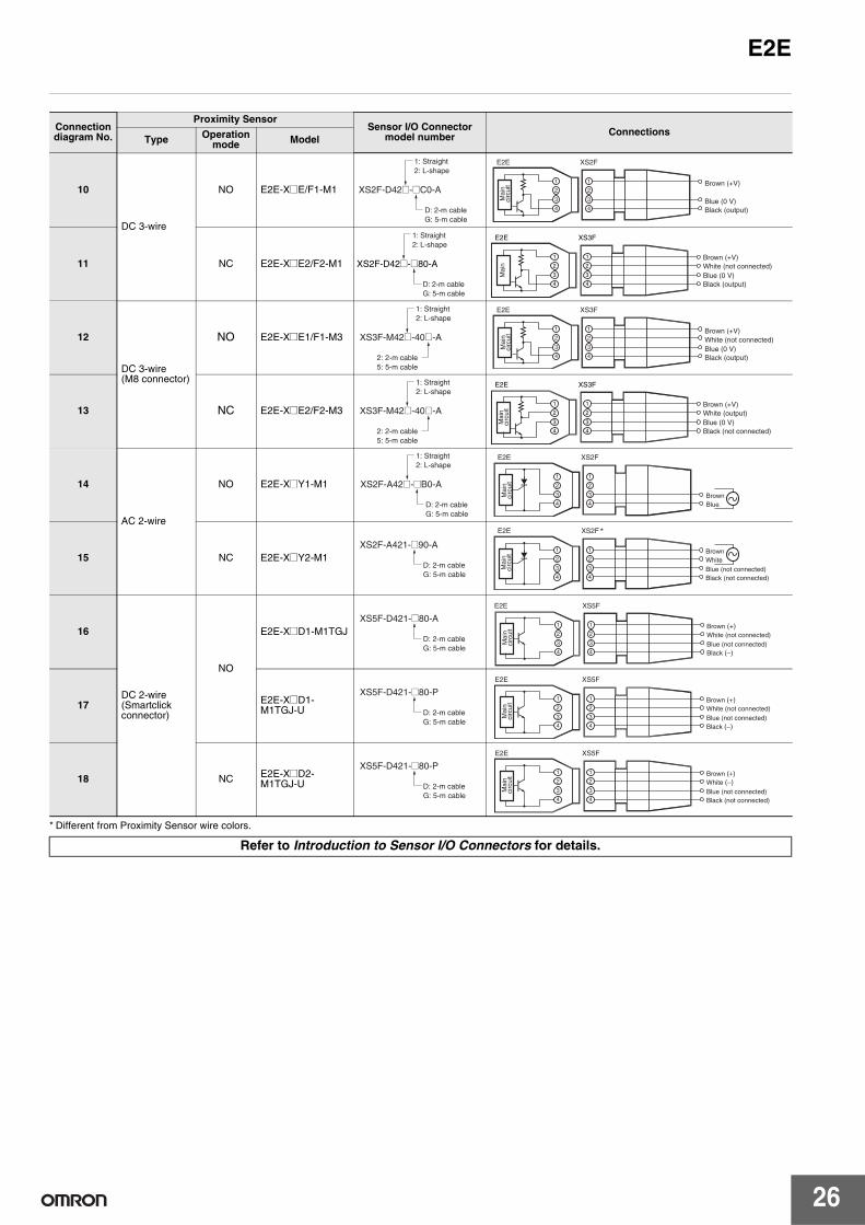
E2E Connections for Sensor I/O Connectors
Connection diagram No.
Proximity Sensor Sensor I/O Connector
model number Connections Type Operation
mode Model
1 DC 2-wire (IEC pin wiring) E2E-X@D1-M1G(J) XS2F-D42@-@A0-A
1: Straight 2: L-shape
E2E
Mai
nci
rcui
t
3
2
1
3
2
1
XS2F
Brown (+)
NO
E2E-X@D1-M1
E2E-X@D1-M1J-T
D: 2-m cable G: 5-m cable
XS2F-D42@-@D0
1: Straight 2: L-shape
D: 2-m cable G: 5-m cable
XS2F-D42@-@D0
1: Straight 2: L-shape
D: 2-m cable G: 5-m cable
1: Straight 2: L-shape
4
2
4
3
1
E2E
Mai
nci
rcui
t
4
3
2
1
E2E
Mai
nci
rcui
t
E2E
4
4
3
2
1
XS2F
4
3
2
1
XS2F
XS3F *
Blue (−)
Blue (−) Brown (+)
Blue (+) (−) Brown (−) (+)
2 DC 2-wire (previous pin wiring)
3 DC 2-wire (no polarity)
4 DC 2-wire (M8 connector)
NC
E2E-X@D1-M3G
E2E-X@D1S-M1
E2E-X@D2-M1G(J)
E2E-X@D2-M1
E2E-X@D2-M1J-T
E2E-X@D2-M3G
XS3F-M42@-40@-A
2: 2-m cable 5: 5-m cable
XS2F-D42@-@80-A
1: Straight 2: L-shape
D: 2-m cable G: 5-m cable
XS2F-D42@-@80-A
1: Straight 2: L-shape
D: 2-m cable G: 5-m cable
XS2F-D42@-@80-A
1: Straight 2: L-shape
D: 2-m cable G: 5-m cable
XS2F-D42@-@80-A
1: Straight 2: L-shape
D: 2-m cable G: 5-m cable
XS3F-M42@-40@-A
1: Straight 2: L-shape
2: 2-m cable 5: 5-m cable
4
3
2
1
Mai
nci
rcui
t
4
3
2
1
E2E
Mai
nci
rcui
t
4
3
2
1
E2EM
ain
circ
uit
4
3
2
1
E2E
Mai
nci
rcui
t
4
3
2
1
E2E
Mai
nci
rcui
t
4
3
2
1
E2E
Mai
nci
rcui
t
4
3
2
1
XS2F *
4
3
2
1
XS2F *
4
3
2
1
XS2F *
4
3
2
1
XS2F *
4
3
2
1
XS3F *
4
3
2
1
Brown (+) White (not connected) Blue (not connected)
Black (−)
Brown (not connected) White (diagnostic output) (+) Blue (0 V) Black (control output) (+)
White (−) Blue (not connected)
Brown (+)
Black (not connected)
White (+) Blue (−)
Brown (not connected)
Black (not connected)
White (−)(+) Blue (not connected)
Brown (+)(−)
Black (not connected)
White (−) Blue (not connected)
Brown (+)
Black (not connected)
5
6
DC 2-wire (diagnostic type)
DC 2-wire (IEC pin wiring)
7 DC 2-wire (previous pin wiring)
8 DC 2-wire (no polarity)
9 DC 2-wire (M8 connector)
* Different from Proximity Sensor wire colors.
25
E2E
* Different from Proximity Sensor wire colors.
Connection diagram No.
Proximity Sensor Sensor I/O Connector
model number Connections Type Operation
mode Model
10
DC 3-wire
NO E2E-X@E/F1-M1
11 NC E2E-X@E2/F2-M1
12
DC 3-wire (M8 connector)
NO E2E-X@E1/F1-M3
13 NC E2E-X@E2/F2-M3
14
AC 2-wire
NO E2E-X@Y1-M1
15 NC E2E-X@Y2-M1
16
DC 2-wire (Smartclick connector)
NO
E2E-X@D1-M1TGJ
17 E2E-X@D1M1TGJ-U
18 NC E2E-X@D2M1TGJ-U
XS2F-D42@-@C0-A
1: Straight 2: L-shape
D: 2-m cable G: 5-m cable
XS2F
4
3
2
1
4
3
2
1
E2E
Brown (+V)
Blue (0 V) Black (output)
Mai
nci
rcui
t
XS2F-D42@-@80-A
1: Straight 2: L-shape
D: 2-m cable G: 5-m cable
XS3F
4
3
2
1
4
3
2
1
E2E
Brown (+V) White (not connected) Blue (0 V) Black (output)
Mai
n
XS3F-M42@-40@-A
1: Straight 2: L-shape
2: 2-m cable 5: 5-m cable
XS3F
4
3
2
1
4
3
2
1
E2E
Brown (+V) White (not connected) Blue (0 V) Black (output)
Mai
nci
rcui
t
XS3F-M42@-40@-A
1: Straight 2: L-shape
2: 2-m cable 5: 5-m cable
XS3F
4
3
2
1
4
3
2
1
E2E
Brown (+V) White (output) Blue (0 V) Black (not connected)
Mai
nci
rcui
t
XS2F-A42@-@B0-A
1: Straight 2: L-shape
D: 2-m cable G: 5-m cable
XS2F
4
3
2
1
4
3
2
1
E2E
Brown Blue
Mai
nci
rcui
t
XS2F-A421-@90-A
D: 2-m cable G: 5-m cable
*XS2F
4
3
2
1
4
3
2
1
E2E
Blue (not connected) Black (not connected)
Brown White
Mai
nci
rcui
t
XS5F-D421-@80-A
D: 2-m cable G: 5-m cable
XS5F
4
3
2
1
4
3
2
1
E2E
Blue (not connected) Black (−)
Brown (+) White (not connected)
Mai
nci
rcui
t
XS5F-D421-@80-P
D: 2-m cable G: 5-m cable
XS5F
4
3
2
1
4
3
2
1
E2E
Blue (not connected) Black (−)
Brown (+) White (not connected)
Mai
nci
rcui
t
XS5F-D421-@80-P
D: 2-m cable G: 5-m cable
XS5F
4
3
2
1
4
3
2
1
E2E
Blue (not connected) Black (not connected)
Brown (+) White (−)
Mai
nci
rcui
t
Refer to Introduction to Sensor I/O Connectors for details.
26

E2E Safety Precautions
Refer to Warranty and Limitations of Liability.
WARNINGThis product is not designed or rated for ensuring safety of persons either directly or indirectly. Do not use it for such purposes.
CAUTION• Do not short the load. Explosion or burning may
result. • Do not supply power to the Sensor with no load,
otherwise Sensor may be damaged. Applicable Models E2E-CR6@ E2E-CR8@ E2E-X1@ Relationship between Sizes and E2E-C1@ Models
Precautions for Correct Use Do not use this product under ambient conditions that exceed the ratings.
● Design Influence of Surrounding Metal When mounting the Sensor within a metal panel, ensure that the clearances given in the following table are maintained. Failure to maintain these distances may cause deterioration in the performance of the Sensor.
l
m n
m D
d dia.
l
Influence of Surrounding Metal (Unit: mm)
Model Item M8 M12 M18 M30 l 0 d 8 12 18 30
Shielded D 0
DC 2-Wire Models E2E-X@D@
AC/DC 2-Wire Models
m 4.5 8 20 40 n 12 18 27 45 l 12 15 22 30
E2E-X@T1 d 24 40 70 90 Unshielded D 12 15 22 30
m 8 20 40 70 n 24 40 70 90 l 0 d 8 12 18 30
DC 3-Wire Models E2E-X@E@ E2E-X@F@
AC 2-Wire Models E2E-X@Y@
Shielded D 0 m 4.5 8 20 40 n 12 18 27 45 l 6 15 22 30 d 24 40 55 90
Unshielded D 6 15 22 30 m 8 20 40 70 n 24 36 54 90
Model Item 3 dia. 4 dia. M5 5.4 dia. l 0
DC 3-Wire Models d 3 4 5 5.4 E2E-X@C/B@ E2E-C@C/B@
Shielded D 0 m 2 2.4 3 n 6 8
Model Model 3 dia. E2E-CR6C/B
4 dia. E2E-CR8C@
E2E-CR8B@
M5 Shielded E2E-X1C@
E2E-X1B@
5.4 dia.
E2E-C1C@
E2E-C1B@
E2E-X2D@
Shielded E2E-X1R5E@
E2E-X1R5F@
M8 E2E-X1R5Y@
E2E-X4MD@
Unshielded E2E-X2ME@
E2E-X2MF@
E2E-X2MY@
Shielded
E2E-X3D@
E2E-X2E@
E2E-X2F@
E2E-X2Y@
M12 E2E-X3T1 E2E-X8MD@
Unshielded E2E-X5ME@
E2E-X5MF@
E2E-X5MY@
E2E-X7D@
Shielded E2E-X5E@
E2E-X5F@
E2E-X5Y@
M18 E2E-X7T1 E2E-X14MD@
Unshielded E2E-X10ME@
E2E-X10MF@
E2E-X10MY@
Shielded
E2E-X10D@
E2E-X10E@
E2E-X10F@
E2E-X10Y@
M30 E2E-X10T1 E2E-X20MD@
Unshielded E2E-X18ME@
E2E-X18MF@
E2E-X18MY@
27

E2E
Mutual Interference Mutual Interference (Unit: mm)
When installing Sensors face-to-face or side-by-side, ensure that the minimum distances given in the following table are maintained.
Model Item M8 M12 M18 M30
DC 2-Wire Models E2E-X@D@
AC/DC 2-Wire Models E2E-X@T1
Shielded A 20 30 (20) 50 (30) 100 (50)
B 15 20 (12) 35 (18) 70 (35)
Unshielded A 80 120 (60) 200 (100) 300 (100)
B 60 100 (50) 110 (60) 200 (100)
DC 3-Wire Models E2E-X@E@/X@F@
AC 2-Wire Models E2E-X@Y@
Shielded A 20 30 (20) 50 (30) 100 (50)
B 15 20 (12) 35 (18) 70 (35)
Unshielded A 80 120 (60) 200 (100) 300 (100)
B 60 100 (50) 110 (60) 200 (100)
A
B Model Item 3 dia. 4 dia. M5 5.4 dia.
DC 3-Wire Models E2E-X@C/B@ E2E-C@C/B@
Shielded A 20
B 15
Note: Values in parentheses apply to Sensors operating at different frequencies.
Loads with Large Surge Currents (E2E-X@T@) If a load with a large surge current is connected, such as a relay, lamp, or motor, the surge current may cause the load short-circuit protection circuit to operate, resulting in operating errors.
● Mounting
Tightening Force Do not tighten the nut with excessive force. A washer must be used with the nut.
Shielded Models Unshielded Models
Part B Part A Part B Part A
Note: 1. The allowable tightening strength depends on the distance from the edge of the head, as shown in the following table. (A is the distance from the edge of the head. B includes the nut on the head side. If the edge of the nut is in part A, the tightening torque for part A applies instead.)
2. The following strengths assume washers are being used.
Refer to the following to mount the E2E-CR6, E2E-CR8 and E2E-C1 Unthreaded Cylindrical Models.
E2E-CR6 9 to 21 mm E2E-CR8, E2E-C1 8 to 21 mm
Dimpled end of set screw (M3)
(No screws are provided with the E2E-CR8 or E2E-C1.)
When using a set screw, tighten it to a torque of 0.2 N·m max. (E2E-C1: 0.4 N·m max.)
Model Part A Part B
Dimension Torque Torque
M5 1 N·m
M8 Shielded 9
9 N·m 12 N·m Unshielded 3
M12 30 N·m
M18 70 N·m
M30 180 N·m
Connecting a DC 2-Wire Proximity Sensor to a PLC (Programmable Controller) Required Conditions Connection to a PLC is possible if the specifications of the PLC and the Proximity Sensor satisfy the following conditions. (The meanings of the symbols are given at the right.) 1. The ON voltage of the PLC and the residual voltage of the Proximity Sensor must satisfy the following.
VON ≤ VCC− VR
2. The OFF current of the PLC and the leakage current of the Proximity Sensor must satisfy the following. IOFF ≥ Ileak
(If the OFF current is not listed in the PLC’s input specifications, take it to be 1.3 mA.) 3. The ON current of the PLC and the control output of the Proximity Sensor must satisfy the following.
IOUT (min.) ≤ ION ≤ IOUT (max.) The ON current of the PLC will vary, however, with the power supply voltage and the input impedance, as shown in the following equation. ION = (VCC − VR − VPC)/RIN
Example In this example, the above conditions are checked when the PLC Unit is the C200H-ID212, the Proximity Sensor is the E2E-X7D1-N, and the power supply voltage is 24 V. 1. VON (14.4 V) ≤ VCc (20.4 V) − VR (3 V) = 17.4 V:OK 2. IOFF (1.3 mA) ≥ Ileak (0.8 mA): OK 3. ION = [VCC (20.4 V) − VR (3 V) − VPLC (4 V)]/RIN (3 kΩ) = Approx. 4.5 mA
Therefore, IOUT (min.) (3 mA) ≤ ION (4.5 mA): OK Connection is thus possible.
VON:ON voltage of PLC (14.4 V) ION: ON current of PLC (typically 7 mA) IOFF: OFF current of PLC (1.3 mA) RIN: Input impedance of PLC (3 kΩ) VPC: Internal residual voltage of PLC (4 V) VR: Output residual voltage of Proximity Sensor
(3 V) Ileak: Leakage current of Proximity Sensor
(0.8 mA) IOUT Control output of Proximity Sensor (3 to
100 mA) VCC: Power supply voltage (PLC: 20.4 to 26.4 V) Values in parentheses apply to the following PLC model and Proximity Sensor model. PLC: C200H-ID212 Sensor: E2E-X7D1-N
28

E2E (Unit: mm) Dimensions Tolerance class IT16 applies to dimensions in this data sheet unless otherwise specified.
Main Units Model Number-Dimensions Drawing Number Lookup Table
Model DC 2-Wire Models DC 3-Wire Models AC 2-Wire Models AC/DC 2-Wire Models Model Shielded Model No. Model No. Model No. Model No.
3 dia. E2E-CR6@ 1
------
4 dia. ---
E2E-CR8@ 2
M5 E2E-X1@ 4
Pre-wired Models
Shielded 5.4 dia. E2E-C1@ 3
M8 E2E-X2D@ 5 E2E-X1R5E@/F@ 5 E2E-X1R5Y@ 7
M12 E2E-X3D@ 9 E2E-X2E@/F@ 9 E2E-X2Y@ 11 E2E-X3T1 13
M18 E2E-X7D@ 14 E2E-X5E@/F@ 14 E2E-X5Y@ 14 E2E-X7T1 14
M30 E2E-X10D@ 16 E2E-X10E@/F@ 16 E2E-X10Y@ 16 E2E-X10T1 16
Unshielded
M8 E2E-X4MD@ 6 E2E-X2ME@/F@ 6 E2E-X2MY@ 8
---M12 E2E-X8MD@ 10 E2E-X5ME@/F@ 10 E2E-X5MY@ 12
M18 E2E-X14MD@ 15 E2E-X10ME@/F@ 15 E2E-X10MY@ 15
M30 E2E-X20MD@ 17 E2E-X18ME@/F@ 17 E2E-X18MY@ 17
Connector Models (M12)
Shielded
M8 E2E-X2D@-M1(G) 18 E2E-X1R5E/F@-M1 18 ---
---M12 E2E-X3D@-M1(G) 20 E2E-X2E/F@-M1 20 E2E-X2Y@-M1 22
M18 E2E-X7D@-M1(G) 24 E2E-X5E/F@-M1 24 E2E-X5Y@-M1 24
M30 E2E-X10D@-M1(G) 26 E2E-X10E/F@-M1 26 E2E-X10Y@-M1 26
Unshielded
M8 E2E-X4MD@-M1(G) 19 E2E-X2ME/F@-M1 19 ---
---M12 E2E-X8MD@-M1(G) 21 E2E-X5ME/F@-M1 21 E2E-X5MY@-M1 23
M18 E2E-X14MD@-M1(G) 25 E2E-X10ME/F@-M1 25 E2E-X10MY@-M1 25
M30 E2E-X20MD@-M1(G) 27 E2E-X18ME/F@-M1 27 E2E-X18MY@-M1 27
Connector Shielded E2E-X2D@-M3G 28 E2E-X1R5E/F@-M3 28 --- ---Models
(M8) Unshielded M8
E2E-X4MD@-M3G 29 E2E-X2ME/F@-M3 29
Pre-wired Connector Models
Shielded
M8 E2E-X2D@-M1(T)GJ(-U) 30
--- --- ---M12 E2E-X3D@-M1(T)GJ(-U) 31
M18 E2E-X7D@-M1(T)GJ(-U) 33
M30 E2E-X10D@-M1(T)GJ(-U) 35
Unshielded
M12 E2E-X8MD1-M1(T)GJ 32
--- --- ---M18 E2E-X14MD1-M1(T)GJ 34
M30 E2E-X20MD1-M1(T)GJ 36
Pre-wired Connector Models (no polarity)
Shielded
M12 E2E-X3D1-M1J-T 31
--- --- ---M18 E2E-X7D@-M1J-T 33
M30 E2E-X10D@-M1J-T 35
Note 1. Two clamping nuts and one toothed washer are provided with M8 to M30 Models. 2. The model numbers of M8 to M30 Pre-wired Models are laser-marked on the milled section and cable section. This does not apply, however, to models that
end in -U.
Pre-wired Models (Shielded)
Diagram 1 E2E-CR6B@/CR6C@
27
17
* Operation indicator (red)
*2.4-dia. vinyl-insulated round cable with 3 conductors (Conductor cross section: 0.08 mm2, Insulator diameter: 0.7 mm)
3 ±0.1 dia.
Diagram 2 E2E-CR8B@/CR8C@ 4 dia. 25
17.5
* Operation indicator (red)
*2.9-dia. vinyl-insulated round cable with 3 conductors (Conductor cross section: 0.14 mm2, Insulator diameter: 0.9 mm), Standard length: 2 m Robotics Cable Models: 2.9-dia. vinyl-insulated round cable with 3 conductors (Conductor cross section: 0.15 mm2, Insulator diameter: 1.05 mm), Standard length: 2 m The cable can be extended up to 100 m (separate metal conduit).
Diagram 3 E2E-C1B@/C1C@ 25
5.4 dia. 17.5
* Operation indicator (red)
*2.9-dia. vinyl-insulated round cable with 3 conductors (Conductor cross section: 0.14 mm2, Insulator diameter: 0.9 mm), Standard length: 2 m Robotics Cable Models: 2.9-dia. vinyl-insulated round cable with 3 conductors (Conductor cross section: 0.15 mm2, Insulator diameter: 1.05 mm), Standard length: 2 m The cable can be extended up to 100 m (separate metal conduit).
Mounting Hole Dimensions
F
Dimension 3 dia. 4 dia. 5.4 dia. F (mm) 3.3 dia. +0.3
0 4.2 dia. +0.5 0 5.7 +0.5
0 dia.
29

13
17
E2E
Pre-wired Models Mounting Hole Dimensions (Shielded)
Dimension M5 M8 M12 F (mm) 5.5 dia. +0.5
0 8.5 dia.+0.5 0 12.5 dia. +0.5
0
F
Diagram 4 E2E-X1B@/X1C@
10 dia. 17.5
25
158
M5 × 0.5 4
* Operation indicator (red)
Two clamping nuts Two toothed washers
*2.9-dia. vinyl-insulated round cable with 3 conductors (Conductor cross section: 0.14 mm2, Insulator diameter: 0.9 mm), Standard length: 2 m Robotics Cable Models: 2.9-dia. vinyl-insulated round cable with 3 conductors (Conductor cross section: 0.15 mm2, Insulator diameter: 1.05 mm), Standard length: 2 m The cable can be extended up to 100 m (separate metal conduit).
Pre-wired Models (Unshielded)
Diagram 5 E2E-X2D@ E2E-X1R5E@/F@
15 dia. 30 7
8 26
3
M8 × 1
*1Indicators *2
Two clamping nuts
13
Toothed washer
*1. 4-dia. vinyl-insulated round cable with 2 conductors (Conductor cross section: 0.3 mm2, Insulator diameter: 1.3 mm), Standard length: 2 m
4-dia. vinyl-insulated round cable with 3 conductors (Conductor cross section: 0.3 mm2, Insulator diameter: 1.3 mm), Standard length: 2 m
Robotics Cable Models: 4-dia. vinyl-insulated round cable with 2 conductors (Conductor cross section: 0.3 mm2, Insulator diameter:
1.27 mm), Standard length: 2 m 4-dia. vinyl-insulated round cable with 3 conductors (Conductor cross section: 0.3 mm2, Insulator diameter:
1.27 mm), Standard length: 2 m Models with Highly Oil-resistant Cables: 4-dia. polyurethane-insulated round cable with 2 conductors (Conductor cross section: 0.3 mm2, Insulator
diameter: 1.3 mm), Standard length: 2 m The cable can be extended up to 200 m (separate metal conduit). *2. D1 Models: Operation indicator (red) and setting indicator (green), D2/E/F Models: Operation indicator (red)
Diagram 6 E2E-X4MD@ E2E-X2ME@/F@
15 dia.
13
30 7
8
26
6 3
M8 × 1
6.1 dia. *1
Indicators *2 Two clamping nuts
Toothed washer
*1. 4-dia. vinyl-insulated round cable with 2 conductors (Conductor cross section: 0.3 mm2, Insulator diameter: 1.3 mm), Standard length: 2 m
4-dia. vinyl-insulated round cable with 3 conductors (Conductor cross section: 0.3 mm2, Insulator diameter: 1.3 mm), Standard length: 2 m
Robotics Cable Models: 4-dia. vinyl-insulated round cable with 2 conductors (Conductor cross section: 0.3 mm2, Insulator diameter: 1.27
mm), Standard length: 2 m 4-dia. vinyl-insulated round cable with 3 conductors (Conductor cross section: 0.3 mm2, Insulator diameter: 1.27
mm), Standard length: 2 m The cable can be extended up to 200 m (separate metal conduit). *2. D1 Models: Operation indicator (red) and setting indicator (green), D2/E/F Models: Operation indicator (red)
Diagram 7 E2E-X1R5Y@
15 dia. 36
3 8
740
*
M8 × 1 Operation indicator (red) Two clamping nuts
Toothed 4-dia. vinyl-insulated round cable with 2 conductors washer (Conductor cross section: 0.3 mm2, Insulator
diameter: 1.3 mm), Standard length: 2 m The cable can be extended up to 200 m (separate metal conduit).
Diagram 8 E2E-X2MY@
15 dia.
40 7
8
36
6 3
M8 × 1
6.1 dia. *
Operation indicator (red) Two clamping nuts
13
Toothed 4-dia. vinyl-insulated round cable with 2 conductors
washer (Conductor cross section: 0.3 mm2, Insulator diameter: 1.3 mm), Standard length: 2 m The cable can be extended up to 200 m (separate metal conduit).
Diagram 9 E2E-X3D@ Pre-wired e-CON Connector Models 5.9
E2E-X2E@/F@ 38 9
33
M12 × 1 Two clamping nuts
4
21 dia.
15.6 4 3
2
15
1
10 Connector: Product code 37104-3163-000FL (Sumitomo 3M)
*1 Indicators * 2
Toothed washer
*1. 4-dia. vinyl-insulated round cable with 2 conductors (Conductor cross section: 0.3 mm2, Insulator diameter: 1.3 mm), Standard length: 2 m
4-dia. vinyl-insulated round cable with 3 conductors (Conductor cross section: 0.3 mm2, Insulator diameter: 1.3 mm), Standard length: 2 m
Robotics Cable Models: 4-dia. vinyl-insulated round cable with 2 conductors (Conductor cross section: 0.3 mm2, Insulator diameter: 1.27
mm), Standard length: 2 m4-dia. vinyl-insulated round cable with 3 conductors (Conductor cross section: 0.3 mm2, Insulator diameter: 1.27
mm), Standard length: 2 m Models with Highly Oil-resistant Cables: 4-dia. polyurethane-insulated round cable with 2 conductors (Conductor cross section: 0.3 mm2, Insulator
diameter: 1.3 mm), Standard length: 2 mThe cable can be extended (separate metal conduit) up to 200 m for the control output and up to 100 m for the
diagnostic output.*2. D1 Models: Operation indicator (red) and setting indicator (green), D2/E/F Models: Operation indicator (red)
Diagram 10 E2E-X8MD@ Pre-wired e-CON Connector Models
E2E-X5ME@/F@ 1 5.9
2
15 3 421 dia. 38 9
10 33
7 4
9 dia.
M12 × 1
*1 Indicators *2
15.6 Connector: Product code 37104-3163-000FL (Sumitomo 3M)17
Two clamping nuts Toothed washer
*1. 4-dia. vinyl-insulated round cable with 2 conductors (Conductor cross section: 0.3 mm2, Insulator diameter: 1.3 mm), Standard length: 2 m
4-dia. vinyl-insulated round cable with 3 conductors (Conductor cross section: 0.3 mm2, Insulator diameter: 1.3 mm), Standard length: 2 m
Robotics Cable Models: 4-dia. vinyl-insulated round cable with 2 conductors (Conductor cross section: 0.3 mm2, Insulator diameter: 1.27
mm), Standard length: 2 m 4-dia. vinyl-insulated round cable with 3 conductors (Conductor cross section: 0.3 mm2, Insulator diameter: 1.27
mm), Standard length: 2 m The cable can be extended (separate metal conduit) up to 200 m for the control output and up to 100 m for the
diagnostic output. *2. D1 Models: Operation indicator (red) and setting indicator (green), D2/E/F Models: Operation indicator (red)
30

E2E
Diagram 11 E2E-X2Y@
21 dia.
17
43 9
10
38
4
*
Operation indicator (red) Two clamping nuts
M12 × 1
Toothed 4-dia. vinyl-insulated round cable with 2
washer conductors (Conductor cross section: 0.3 mm2, Insulator diameter: 1.3 mm), Standard length: 2 m The cable can be extended up to 200 m (separate metal conduit).
Pre-wired Models (Shielded)
Mounting Hole Dimensions
Diagram 12 E2E-X5MY@
21 dia. 43 9
10
38
7 4
M12 × 1
9 dia. *
Operation indicator (red) Two clamping nuts
17
Toothed 4-dia. vinyl-insulated round cable with 2 washer conductors (Conductor cross section: 0.3 mm2,
Insulator diameter: 1.3 mm), Standard length: 2 m The cable can be extended up to 200 m (separate metal conduit).
F
Diagram 13 E2E-X3T1
21 dia.
17
M12 × 1
Toothed *1 4-dia. vinyl-insulated round cable with 2
60 9
10
55
4
Two clamping nuts
*1 Indicators *2
washer conductors (Conductor cross section: 0.3 mm2, Insulator diameter: 1.3 mm), Standard length: 2 m The cable can be extended up to 200 m (separate metal conduit).
*2 Operation indicator (red), Setting indicator (green)
Dimension M8 M12 M18 M30 F (mm) 8.5 dia. +0.5
0 12.5 dia. +0.5 0 18.5 dia. +0.5
0 30.5 dia. +0.5 0
Pre-wired Models (Unshielded)
Diagram 14 E2E-X7D@/E2E-X5E@/F@ E2E-X5Y@/E2E-X7T1
Pre-wired e-CON Connector Models 5.9
4 3
2
15
1
15.643 12 Connector: Product code
29 dia. 37104-2206-000FL (Sumitomo 3M)
38
10424
*1 Indicators *2
M18 × 1 Two clamping nuts Toothed washer
*1. 6-dia. vinyl-insulated round cable with 2 conductors (Conductor cross section: 0.5 mm2, Insulator diameter: 1.9 mm), Standard length: 2 m
6-dia. vinyl-insulated round cable with 3 conductors (Conductor cross section: 0.5 mm2, Insulator diameter: 1.9 mm), Standard length: 2 m
Robotics Cable Models: 6-dia. vinyl-insulated round cable with 2 conductors (Conductor cross section: 0.5 mm2,
Insulator diameter: 1.74 mm), Standard length: 2 m 6-dia. vinyl-insulated round cable with 3 conductors (Conductor cross section: 0.5 mm2,
Insulator diameter: 1.74 mm), Standard length: 2 m Models with Highly Oil-resistant Cables: 6-dia. polyurethane-insulated round cable with 2 conductors (Conductor cross section: 0.5
mm2, Insulator diameter: 1.9 mm), Standard length: 2 m The cable can be extended (separate metal conduit) up to 200 m for the control output and
up to 100 m for the diagnostic output. *2. D1/T Models: Operation indicator (red), Setting indicator (green) D2/E/F/Y Models: Operation indicator (red)
Diagram 15 E2E-X14MD@/E2E-X10ME@/F@ E2E-X10MY@ Pre-wired e-CON
Connector Models 5.9
10
43 12
10
38
4
M18 × 1
14.8 dia. *1*1
Indicators *2
Two clamping nuts Toothed washer
4 3
2
15
1
15.6 Connector: Product code 37104-2206-000FL (Sumitomo 3M)
24
29 dia.
*1. 6-dia. vinyl-insulated round cable with 2 conductors (Conductor cross section: 0.5 mm2, Insulator diameter: 1.9 mm), Standard length: 2 m
6-dia. vinyl-insulated round cable with 3 conductors (Conductor cross section: 0.5 mm2, Insulator diameter: 1.9 mm), Standard length: 2 m
Robotics Cable Models: 6-dia. vinyl-insulated round cable with 2 conductors (Conductor cross section: 0.5 mm2,
Insulator diameter: 1.74 mm), Standard length: 2 m 6-dia. vinyl-insulated round cable with 3 conductors (Conductor cross section: 0.5 mm2,
Insulator diameter: 1.74 mm), Standard length: 2 m The cable can be extended (separate metal conduit) up to 200 m for the control output
and up to 100 m for the diagnostic output. *2. D1/T Models: Operation indicator (red), Setting indicator (green) D2/E/F/Y Models: Operation indicator (red)
31

13
E2E
Diagram 16 E2E-X10D@/E2E-X10E@/F@ E2E-X10Y@/E2E-X10T1
Pre-wired e-CON Connector Models 5.9
48 12
10 43
536
42 dia.
M30 × 1.5
*1 Indicators *2
Two clamping nuts
4 3
2
15
1
15.6 Connector: Product code 37104-2206-000FL (Sumitomo 3M)
Toothed washer *1. 6-dia. vinyl-insulated round cable with 2 conductors (Conductor cross section: 0.5 mm2,
Insulator diameter: 1.9 mm), Standard length: 2 m 6-dia. vinyl-insulated round cable with 3 conductors (Conductor cross section: 0.5 mm2,
Insulator diameter: 1.9 mm), Standard length: 2 m Robotics Cable Models: 6-dia. vinyl-insulated round cable with 2 conductors (Conductor cross section: 0.5 mm2,
Insulator diameter: 1.74 mm), Standard length: 2 m 6-dia. vinyl-insulated round cable with 3 conductors (Conductor cross section: 0.5 mm2,
Insulator diameter: 1.74 mm), Standard length: 2 m Models with Highly Oil-resistant: 6-dia. polyurethane-insulated round cable with 2 conductors (Conductor cross section:
0.5 mm2, Insulator diameter: 1.9 mm), Standard length: 2 m The cable can be extended (separate metal conduit) up to 200 m for the control output
and up to 100 m for the diagnostic output. *2. D1/T Models: Operation indicator (red), Setting indicator (green)
D2/E/F/Y Models: Operation indicator (red)
Diagram 17 E2E-X20MD@/E2E-X18ME@/F@ E2E-X18MY@ Pre-wired e-CON
Connector Models 5.9
4 3
2
15
1
15.6 Connector: Product code
42 dia.
36
Two clamping nuts
48 12
1013
43
5
M30 × 1.5
26.8 dia. *1
Indicators *2
37104-2206-000FL (Sumitomo 3M)
Toothed washer *1. 6-dia. vinyl-insulated round cable with 2 conductors (Conductor cross section: 0.5 mm2,
Insulator diameter: 1.9 mm), Standard length: 2 m 6-dia. vinyl-insulated round cable with 3 conductors (Conductor cross section: 0.5 mm2,
Insulator diameter: 1.9 mm), Standard length: 2 m Robotics Cable Models: 6-dia. vinyl-insulated round cable with 2 conductors (Conductor cross section: 0.5 mm2,
Insulator diameter: 1.74 mm), Standard length: 2 m 6-dia. vinyl-insulated round cable with 3 conductors (Conductor cross section: 0.5 mm2,
Insulator diameter: 1.74 mm), Standard length: 2 m The cable can be extended (separate metal conduit) up to 200 m for the control output
and up to 100 m for the diagnostic output. *2. D1/T Models: Operation indicator (red), Setting indicator (green)
D2/E/F/Y Models: Operation indicator (red)
M8 Connector Models (Shielded)
Diagram 28 E2E-X2D@-M3G/E2E-X1R5E@-M3/X1RF@-M3
15 dia.
* D Models: Operation indicator (red), Setting indicator (green)
D2/E/F Models: Operation indicator (red) M8 ×
M8 × 1
3931
8
26
3
Indicators*Two clamping nuts
1
Toothed washer
M8 Connector Models (Unshielded)
Diagram 29 E2E-X4MD@-M3G/E2E-X2ME@-M3/X2MF@-M3
13
15 dia.
M8 × 1
* D Models: Operation indicator (red), Setting indicator (green)
D2/E/F Models: Operation indicator (red)
39
31
8
26
6 3
M8 × 1
6.1 dia.
Indicators* Two clamping nuts
Toothed washer
M12 Connector Models M12 Connector Models (Shielded) (Unshielded)
Diagram 18 E2E-X2D@-M1(G) E2E-X1R5E@-M1/E2E-X1R5F@-M1
13
15 dia.
3
4330
8
26 M12 × 1
Indicators*M8 × 1 Two clamping nuts
Toothed washer
* D1 Models: Operation indicator (red), Setting indicator (green)
D2/E/F Models: Operation indicator (red)
Diagram 19 E2E-X4MD@-M1(G) E2E-X2ME@-M1/E2E-X2MF@-M1
15 dia. M12 × 1
43
30
8
26
6 3
6.1 dia.
M8 × 1 Indicators* Two clamping nuts
13
Toothed washer
* D1 Models: Operation indicator (red), Setting indicator (green)
D2/E/F Models: Operation indicator (red)
32

E2E
Diagram 20 E2E-X3D@-M1(G) E2E-X2E@-M1/E2E-X2F@-M1
17
21 dia. 48
33
4 10 M12 × 1
Indicators *M12 × 1 Two clamping nuts
Toothed washer
* D1 Models: Operation indicator (red), Setting indicator (green)
D2/E/F Models:Operation indicator (red)
Diagram 22 E2E-X2Y@-M1
17
21 dia.
Diagram 21 E2E-X8MD@-M1(G) E2E-X5ME@-M1/E2E-X5MF@-M1
48
33
10 M12 × 147
9 dia.
Indicators*
17
21 dia.
M12 × 1 Two clamping nuts
Toothed washer
* D1 Models: Operation indicator (red), Setting indicator (green) D2/E/F Models: Operation indicator (red)
Diagram 23 E2E-X5MY@-M1
53
38
17
21 dia.
M12 × 1
53
10
38
4
M12 × 1 Operation indicator (red)
Two clamping nuts
Toothed washer
Diagram 24 E2E-X7D@-M1(G)/E2E-X5E@-M1/X5F@-M1 E2E-X5Y@-M1
29 dia.
24
M12 × 1
M18 × 1
Toothed washer
53
10
38
4
Indicators*
Two clamping nuts
* D1 Models: Operation indicator (red), Setting indicator (green) D2/E/Y Models: Operation indicator (red)
Diagram 26 E2E-X10D@-M1(G)/E2E-X10E@-M1/X10F@-M1 E2E-X10Y@-M1
42 dia.
36
M12 × 1
M30 × 1.5
Toothed washer
58
10
43
5
Indicators*
Two clamping nuts
* D1 Models: Operation indicator (red), Setting indicator (green) D2/E/Y Models: Operation indicator (red)
Mounting Hole Dimensions
M12 × 14 107
9 dia.
Operation indicator (red)M12 × 1
Two clamping nuts Toothed washer
Diagram 25 E2E-X14MD@-M1(G)/E2E-X10ME@-M1 X10MF@-M1 E2E-X10MY@-M1
29 dia.
24
14.8 dia.
M12 × 1
53
10
38
10 4
M18 × 1 Indicators*
Two clamping nuts Toothed washer
* D1 Models: Operation indicator (red), Setting indicator (green) D2/E/Y Models: Operation indicator (red)
Diagram 27 E2E-X20MD@-M1(G)/E2E-X18ME@-M1/ X18MF@-M1 E2E-X18MY@-M1
42 dia.
36
M12 × 1
58
10
43
13 5
M30 × 1.5
26.8 dia.
Indicators*
Two clamping nuts
Toothed washer
* D1 Models: Operation indicator (red), Setting indicator (green) D2/E/Y Models: Operation indicator (red)
F
Dimensions M8 M12 M18 M30 F (mm) 8.5 dia. +0.5
0 12.5 dia. +0.5 0 18.5 dia. +0.5
0 30.5 dia. +0.5 0
33

E2E
Pre-wired Connector Models (Shielded) Mounting Hole Dimensions
Dimension M12 M18 M30 F (mm) 12.5 dia. 18.5 dia. 30.5 dia. +0.5
0 +0.5
0 +0.5
0
F
Diagram 30 E2E-X2D@-M1TGJ-U *3 30 7 15 dia.E2E-X2D1-M1TGJ
13
*1
826
3
M8 × 1 Two clamping nuts
Indicators *2 M12 × 1
*1. No U suffix: 4-dia. Vinyl-insulated round cableToothed washer U suffix: 4-dia. Polyurethane insulated round cable, Standard length: 300 mm
*2. D1 Models: Operation indicator (red), Setting indicator (green) D2 Models: Operation indicator (red)
*3. The connectors for M1TGJ models are XS5 Smartclick connectors.
Diagram 31 E2E-X3D@-M1GJ 21 dia.E2E-X3D1-M1J-T
E2E-X3D@-M1TGJ-U *3 17
E2E-X3D1-M1TGJ
M12 × 1
938
10
33
4
*1
M12 × 1Indicators *2 Two clamping nuts *1. No U suffix: 4-dia. Vinyl-insulated round cable
Toothed washer U suffix: 4-dia. Polyurethane insulated round cable, Standard length: 300 mm
*2. D1 Models: Operation indicator (red), Setting indicator (green) D2 Models: Operation indicator (red)
*3. The connectors for M1TGJ models are XS5 Smartclick connectors.
Diagram 33 E2E-X7D@-M1GJ 29 dia.
E2E-X7D@-M1J-T 24
E2E-X7D@-M1TGJ-U *3E2E-X7D1-M1TGJ
1243
*1
10
38
4
Indicators *2
Toothed washer
Two clamping nuts *1. No U suffix: 6-dia. Vinyl-insulated round cable U suffix: 6-dia. Polyurethane insulated round cable,
Standard length: 300 mm
M12 × 1 M18 × 1
*2. D1 Models: Operation indicator (red), Setting indicator (green) D2 Models: Operation indicator (red)
*3. The connectors for M1TGJ models are XS5 Smartclick connectors.
Diagram 35 E2E-X10D@-M1GJ E2E-X10D@-M1J-T E2E-X10D@-M1TGJ-U *3 E2E-X10D1-M1TGJ
36
42 dia.
M30 × 1.5
1248
10
43
5
*1
M12 × 1 Indicators *2
Toothed washer
Two clamping nuts U suffix: 6-dia. Polyurethane insulated round cable,
*2. D1 Models: Operation indicator (red), Setting indicator (green)
*1. No U suffix: 6-dia. Vinyl-insulated round cable
Standard length: 300 mm
D2 Models: Operation indicator (red) *3. The connectors for M1TGJ models are XS5 Smartclick connectors.
Pre-wired Connector Models (Unshielded)
Diagram 32 E2E-X8MD1-M1GJ 21 dia.
E2E-X8MD1-M1TGJ 17
*2. Operation indicator (red), Setting indicator (green)
938
10
33
7 4
9 dia.
M12 × 1
*1
M12 × 1Indicators *2
Toothed washer Two clamping nuts *1. 4-dia. vinyl-insulated round cable,
Standard length: 300 mm
34

E2E
Diagram 34 E2E-X14MD@-M1GJ E2E-X14MD1-M1TGJ 29 dia.
24
14.8 dia.
1243
10
38
10 4
M18 × 1
*1
Indicators*2
Two clamping nuts *1. 6-dia. vinyl-insulated round cable, Standard
length: 300 mm
M12 × 1
Toothed washer *2. D1 Models: Operation indicator (red), Setting indicator (green) D2 Models: Operation indicator (red)
Diagram 36 E2E-X20MD1-M1GJ 42 dia.E2E-X20MD1-M1TGJ
1248
10
43
13 5
26.8 dia.
M30 × 1.5
Indicators*2
Two clamping nuts
36
*1
M12 × 1
*1. 6-dia. vinyl-insulated round cable, Standard length: 300 mm
Toothed washer *2. Operation indicator (red), Setting indicator (green)
Dimensions for Proximity Sensors with Sensor I/O ConnectorsShielded Models Unshielded Models Dimensions with the XS2F Connected (Unit: mm)
Straight Connectors Straight Connectors Dimension
Sensor diameter L1 L2
M8 Approx. 75 Approx. 62
M12* DC Approx. 80 Approx. 67 AC Approx. 85 Approx. 72
M18 Approx. 85 Approx. 72 M30 Approx. 90 Approx. 77
L1 L1
L-shape Connectors L-shape Connectors
* The overall length of the Sensor is different between AC and DC Models for Sensors with diameters of M12. This will change the dimension when the I/O Connector is connected.
Dimensions with the XS3F Connected (Unit: mm)
L2L2 Dimension
Sensor diameter L1 L2
M8 Approx. 65 Approx. 54
Accessories (Order Separately)
Sensor I/O Connectors Refer to Introduction to Sensor I/O Connectors for details.
Mounting Brackets
Protective Covers
Sputter Protective Covers Refer to Y92@ for details.
35

Read and Understand This Catalog Please read and understand this catalog before purchasing the products. Please consult your OMRON representative if you have any questions or comments.
Warranty and Limitations of Liability
WARRANTY OMRON's exclusive warranty is that the products are free from defects in materials and workmanship for a period of one year (or other period if specified) from date of sale by OMRON.
OMRON MAKES NO WARRANTY OR REPRESENTATION, EXPRESS OR IMPLIED, REGARDING NON-INFRINGEMENT, MERCHANTABILITY, OR FITNESS FOR PARTICULAR PURPOSE OF THE PRODUCTS. ANY BUYER OR USER ACKNOWLEDGES THAT THE BUYER OR USER ALONE HAS DETERMINED THAT THE PRODUCTS WILL SUITABLY MEET THE REQUIREMENTS OF THEIR INTENDED USE. OMRON DISCLAIMS ALL OTHER WARRANTIES, EXPRESS OR IMPLIED.
LIMITATIONS OF LIABILITY OMRON SHALL NOT BE RESPONSIBLE FOR SPECIAL, INDIRECT, OR CONSEQUENTIAL DAMAGES, LOSS OF PROFITS OR COMMERCIAL LOSS IN ANY WAY CONNECTED WITH THE PRODUCTS, WHETHER SUCH CLAIM IS BASED ON CONTRACT, WARRANTY, NEGLIGENCE, OR STRICT LIABILITY.
In no event shall the responsibility of OMRON for any act exceed the individual price of the product on which liability is asserted.
IN NO EVENT SHALL OMRON BE RESPONSIBLE FOR WARRANTY, REPAIR, OR OTHER CLAIMS REGARDING THE PRODUCTS UNLESS OMRON'S ANALYSIS CONFIRMS THAT THE PRODUCTS WERE PROPERLY HANDLED, STORED, INSTALLED, AND MAINTAINED AND NOT SUBJECT TO CONTAMINATION, ABUSE, MISUSE, OR INAPPROPRIATE MODIFICATION OR REPAIR.
Application Considerations
SUITABILITY FOR USE OMRON shall not be responsible for conformity with any standards, codes, or regulations that apply to the combination of products in the customer's application or use of the products.
At the customer's request, OMRON will provide applicable third party certification documents identifying ratings and limitations of use that apply to the products. This information by itself is not sufficient for a complete determination of the suitability of the products in combination with the end product, machine, system, or other application or use.
The following are some examples of applications for which particular attention must be given. This is not intended to be an exhaustive list of all possible uses of the products, nor is it intended to imply that the uses listed may be suitable for the products:
• Outdoor use, uses involving potential chemical contamination or electrical interference, or conditions or uses not described in this catalog.
• Nuclear energy control systems, combustion systems, railroad systems, aviation systems, medical equipment, amusement machines, vehicles, safety equipment, and installations subject to separate industry or government regulations.
• Systems, machines, and equipment that could present a risk to life or property.
Please know and observe all prohibitions of use applicable to the products.
NEVER USE THE PRODUCTS FOR AN APPLICATION INVOLVING SERIOUS RISK TO LIFE OR PROPERTY WITHOUT ENSURING THAT THE SYSTEM AS A WHOLE HAS BEEN DESIGNED TO ADDRESS THE RISKS, AND THAT THE OMRON PRODUCTS ARE PROPERLY RATED AND INSTALLED FOR THE INTENDED USE WITHIN THE OVERALL EQUIPMENT OR SYSTEM.
PROGRAMMABLE PRODUCTS OMRON shall not be responsible for the user's programming of a programmable product, or any consequence thereof.
Disclaimers
CHANGE IN SPECIFICATIONS Product specifications and accessories may be changed at any time based on improvements and other reasons.
It is our practice to change model numbers when published ratings or features are changed, or when significant construction changes are made. However, some specifications of the products may be changed without any notice. When in doubt, special model numbers may be assigned to fix or establish key specifications for your application on your request. Please consult with your OMRON representative at any time to confirm actual specifications of purchased products.
DIMENSIONS AND WEIGHTS Dimensions and weights are nominal and are not to be used for manufacturing purposes, even when tolerances are shown.
PERFORMANCE DATA Performance data given in this catalog is provided as a guide for the user in determining suitability and does not constitute a warranty. It may represent the result of OMRON’s test conditions, and the users must correlate it to actual application requirements. Actual performance is subject to the OMRON Warranty and Limitations of Liability.
ERRORS AND OMISSIONS The information in this document has been carefully checked and is believed to be accurate; however, no responsibility is assumed for clerical, typographical, or proofreading errors, or omissions.
In the interest of product improvement, specifications are subject to change without notice.
OMRON CorporationIndustrial Automation Company
http://www.ia.omron.com/ (c)Copyright OMRON Corporation 2010 All Right Reserved.
2010.8


