
Storage Technologies
for Renewable Energy
Joseph H. Simmons and Ardeth M. Barnhart
Co-Directors
AzRISE – The Arizona Research Institute for Solar Energy
University of Arizona
http://www.azrise.org
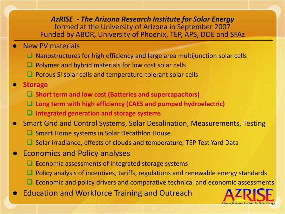
AzRISE - The Arizona Research Institute for Solar Energyformed at the University of Arizona in September 2007
Funded by ABOR, University of Phoenix, TEP, APS, DOE and SFAz
● New PV materials Nanostructures for high efficiency and large area multijunction solar cells
Polymer and hybrid materials for low cost solar cells
Porous Si solar cells and temperature-tolerant solar cells
● Storage Short term and low cost (Batteries and supercapacitors)
Long term with high efficiency (CAES and pumped hydroelectric)
Integrated generation and storage systems
● Smart Grid and Control Systems, Solar Desalination, Measurements, Testing Smart Home systems in Solar Decathlon House
Solar irradiance, effects of clouds and temperature, TEP Test Yard Data
● Economics and Policy analyses Economic assessments of integrated storage systems
Policy analysis of incentives, tariffs, regulations and renewable energy standards
Economic and policy drivers and comparative technical and economic assessments
● Education and Workforce Training and Outreach
The University of Arizona
In alliance with
University of Phoenix
Overview
● Useful Storage Technologies
Batteries
Compressed Air Energy Storage
Thermal Energy Storage
Pumped Hydroelectric
● Opportunities in Arizona
Geology
● Macro-economics of Solar/Renewable Energy (to be presented at the next session by Ardeth M. Barnhart)

The University of Arizona
In alliance with
University of Phoenix
Photovoltaic Modules at the
TEP SOLAR TEST YARD
Alex Cronin
UA Physics
Cost
Reliability
Efficiency
Storage
Transmission
CIGS
Thin Si,
Poly Si
A Field Laboratory
to study
23 Inverters

The University of Arizona
In alliance with
University of Phoenix
Rated Power
2,640 Watts peak
Short-term intermittency due to weather

The University of Arizona
In alliance with
University of Phoenix
Day-to-day Production Variation
The University of Arizona
In alliance with
University of Phoenix
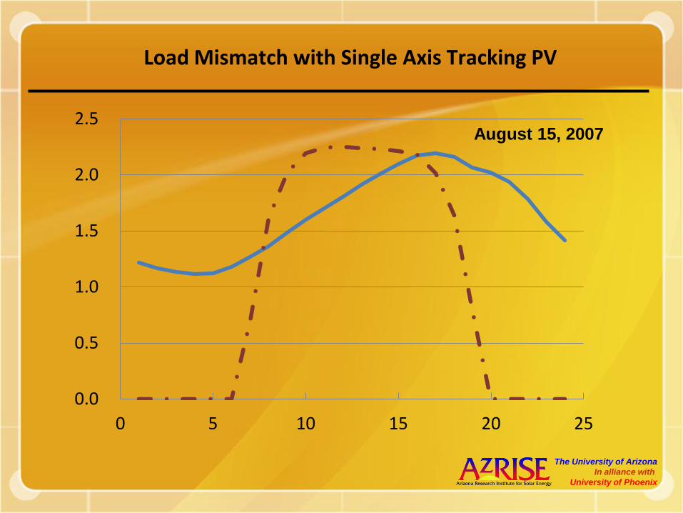
Load Mismatch with Single Axis Tracking PV
0.0
0.5
1.0
1.5
2.0
2.5
0 5 10 15 20 25
August 15, 2007
The University of Arizona
In alliance with
University of Phoenix
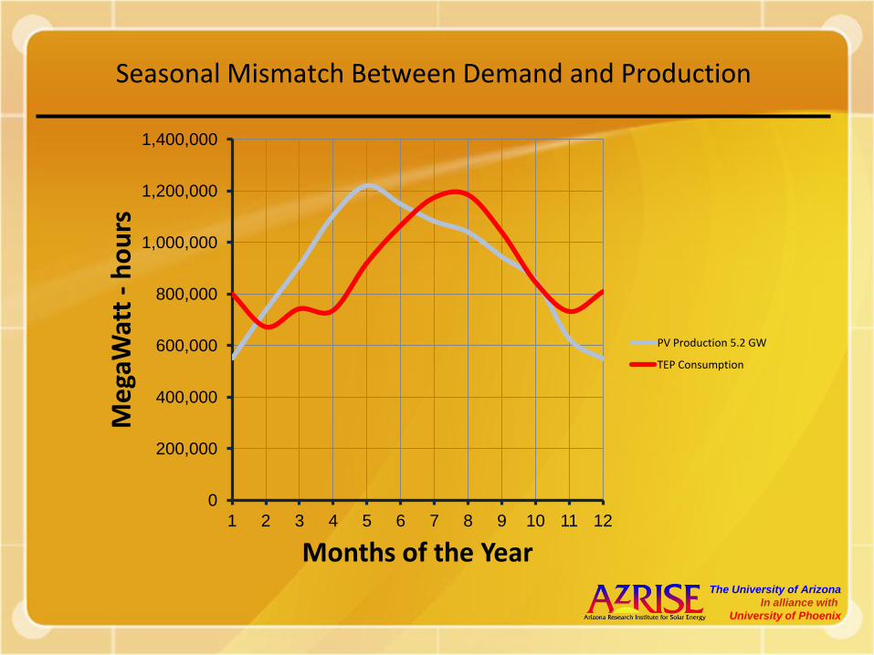
Seasonal Mismatch Between Demand and Production
0
200,000
400,000
600,000
800,000
1,000,000
1,200,000
1,400,000
1 2 3 4 5 6 7 8 9 10 11 12
Me
gaW
att
-h
ou
rs
Months of the Year
PV Production 5.2 GW
TEP Consumption
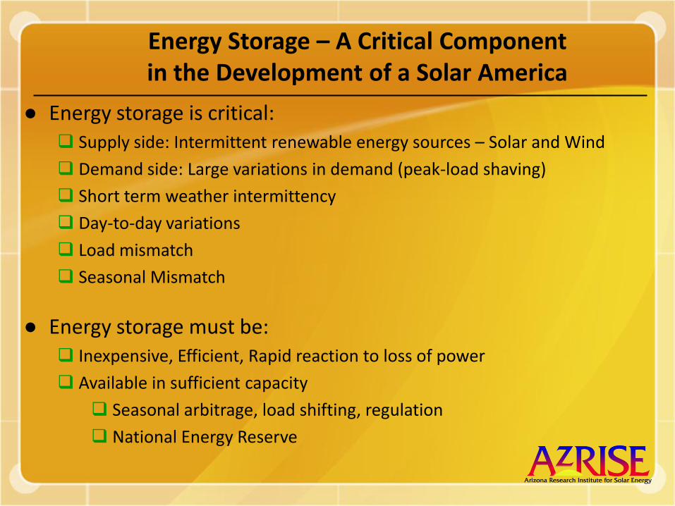
Energy Storage – A Critical Componentin the Development of a Solar America
● Energy storage is critical: Supply side: Intermittent renewable energy sources – Solar and Wind
Demand side: Large variations in demand (peak-load shaving)
Short term weather intermittency
Day-to-day variations
Load mismatch
Seasonal Mismatch
● Energy storage must be: Inexpensive, Efficient, Rapid reaction to loss of power
Available in sufficient capacity
Seasonal arbitrage, load shifting, regulation
National Energy Reserve

Energy Storage
Batteries
Supercapacitors
Flywheels
Hydrogen
Fuel cells
Compressed air in vessels
Underground compressed air
Pumped hydroelectric
Thermal storage
Superconducting magnetic energy

Full power duration of storage technologies
Duration Biomass Hydrogen CAES Thermal Hydroelec Flow cell batteries Supercap
4 mos + + +3 weeks + + +3 days + + + + +6 hours + + + + + + +2 hours + + + + + + +40 min + + + + + +10 min + + + + +20 sec + + +1 second +

Sam Jaffe – ESA 09 (Energy Insights)
Summary of Energy Storage approaches:


Energy Storage – A Critical Componentin the Development of a Solar America
● Compressed Air Energy Storage (CAES)
Above ground (vessels) Storage for a few hoursAutomotive applications
● Underground Compressed Air Storage (1,100 psi, 75 atmo.)
Needs salt deposits (primary)
High efficiency and low price (65-90%)
Needs additional fuel for operating the turbine (natural gas or biofuels)
UA research –
►Adiabatic pump with heat recovery using molten salt storage
►Hydrogen heating for additional fuel
►Salt deposits and alluvium for underground storage
►Mining sites and mine tailing banks
►Demonstration site (Riverpoint Solar Research Park)

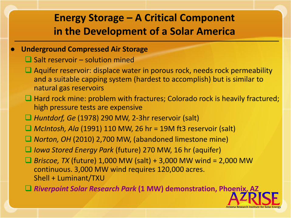
Energy Storage – A Critical Componentin the Development of a Solar America
● Underground Compressed Air Storage
Salt reservoir – solution mined
Aquifer reservoir: displace water in porous rock, needs rock permeability and a suitable capping system (hardest to accomplish) but is similar to natural gas reservoirs
Hard rock mine: problem with fractures; Colorado rock is heavily fractured; high pressure tests are expensive
Huntdorf, Ge (1978) 290 MW, 2-3hr reservoir (salt)
McIntosh, Ala (1991) 110 MW, 26 hr = 19M ft3 reservoir (salt)
Norton, OH (2010) 2,700 MW, (abandoned limestone mine)
Iowa Stored Energy Park (future) 270 MW, 16 hr (aquifer)
Briscoe, TX (future) 1,000 MW (salt) + 3,000 MW wind = 2,000 MW continuous. 3,000 MW wind requires 120,000 acres.Shell + Luminant/TXU
Riverpoint Solar Research Park (1 MW) demonstration, Phoenix, AZ
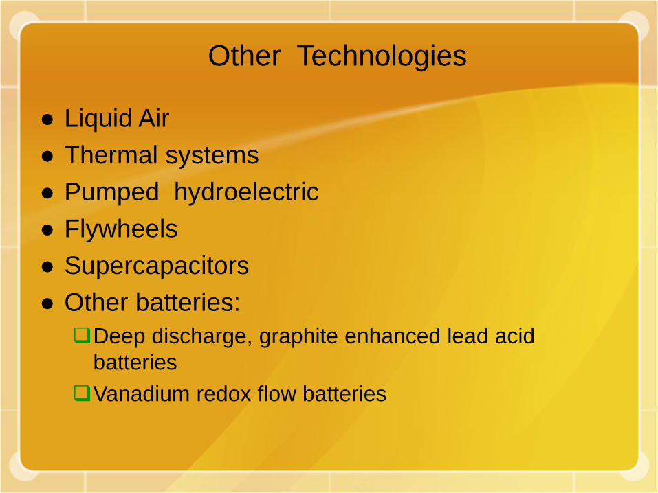
Other Technologies
● Liquid Air
● Thermal systems
● Pumped hydroelectric
● Flywheels
● Supercapacitors
● Other batteries:
Deep discharge, graphite enhanced lead acid
batteries
Vanadium redox flow batteries


CAES Characteristics
● Typical range of operating pressures: 1150 psi – 750 psi
● Energy output per cavern size: 7.3 kWh/m3
● Energy balance: 1 kWh CAES production comes from:
Compression energy: 0.75 kWh
Heating energy: 4,300 BTU (1.25 kWh/0.39 kWh NG)
● Typical round-trip efficiency: 65%
● Potential round-trip efficiency with heat recovery: 85%
● Storage vessels:
Underground salt cavern, abandoned mine
Depleted natural gas well, capped aquifer storage
Alluvium holes
Above-ground steel vessels

Compressed Air Energy Storage
● Generation/storage systems integration
● Efficiency w/o heat recovery: 65%, with: 85%
● Isothermal vs adiabatic pumping
● Turbine vs vessel size
● Costs and economics
● Air Storage:
● Subsurface imaging to greater than 2,000 feet
● Solution mined salt, drilled alluvium
● Depleted natural gas wells, abandoned mines
● Above-ground tanks, underwater tanks
Compressed air storage cavern/above ground vessel
Heat exchanger Gas heater
Gen 1 Gen 2
Gen 3 Gen 4
Bus
Solar Power GeneratorPV, Thermal,
Concentrators
InverterStep-upTrans-former
Step-upTrans-former
WindGenerator
Step-downTrans-former
ACCompressor
DCCompressor
Electric transmission grid
Excess generation
Hot air
Hot air Hot air

Compressed Air Energy Storage
● Generation/storage systems integration
● Efficiency w/o heat recovery: 65%, with: 85%
● Isothermal vs adiabatic pumping
● Turbine vs vessel size
● Costs and economics
Compressed air storage cavern/above ground vessel
Heat exchanger Heat storage Gas heater
Gen 1 Gen 2
Gen 3 Gen 4
Bus
Solar Power GeneratorPV, Thermal,
Concentrators
InverterStep-upTrans-former
Step-upTrans-former
WindGenerator
Step-downTrans-former
ACCompressor
DCCompressor
Electric transmission grid
Excess generation
Hot air Hot air
Hot air Hot air
HEF
● Air Storage:
● Subsurface imaging to greater than 2,000 feet
● Solution mined salt, drilled alluvium
● Depleted natural gas wells, abandoned mines
● Above-ground tanks, underwater tanks

Load Shifting Function

Load Shifting Function – CAES Capacity
(500.000)
0.000
500.000
1,000.000
1,500.000
2,000.000
2,500.000
3,000.000
3,500.000
4,000.000
0 5 10 15 20 25 30
En
erg
y i
n M
Wh

The University of Arizona
In alliance with
University of Phoenix
Addition of CAES to Meet Seasonal Differences
-600,000
-400,000
-200,000
0
200,000
400,000
600,000
800,000
1,000,000
1,200,000
1,400,000
1 2 3 4 5 6 7 8 9 10 11 12Me
gaW
att
-h
ou
rs
Months of the Year
PV Production 5.2 GW
CAES Produced Electricity
TEP Consumption
CAES Stored Energy

Underground Compressed Air Storage in Salt Caverns
● Holbrook salt basin covers 3,500 square miles and is 300 feet thick.
● Holbrook basin has the capacity to store 30TW of electrical production –more that the US total energy demand (3.3 TW) or 30 times the electrical demand (1 TW).
● Many salt basins are distributed throughout Arizona
● Luke, Picacho and Holbrook are currently used to store natural gas or propane


