
American Journal of Energy and Power Engineering 2017; 4(6): 84-88
http://www.aascit.org/journal/ajepe
ISSN: 2375-3897
Keywords Turbocharger,
Compression Ratio,
Simulation,
Engine Performance
Received: October 1, 2017
Accepted: November 1, 2017
Published: December 5, 2017
Studying Turbocharging Effects on Engine Performance and Emissions by Various Compression Ratios
Ali Mirmohammadi1, *
, Amin Kalhor2
1Department of Mechanical Engineering, Shahid Rajaee Teacher Training University, Tehran, Iran 2Department of Shahid Beheshti, Technical and Vocational University, Karaj, Iran
Email address [email protected] (A. Mirmohammadi) *Corresponding author
Citation Ali Mirmohammadi, Amin Kalhor. Studying Turbocharging Effects on Engine Performance and
Emissions by Various Compression Ratios. American Journal of Energy and Power Engineering.
Vol. 4, No. 6, 2017, pp. 84-88.
Abstract According to the Global Fuel Crisis, it seems necessary to increase the efficiency of
internal combustion engines. One way for achieve this target, is engine downsizing by
using turbocharger. Turbocharger using makes combustion more efficient and better. The
purpose of this paper is studying effect of turbocharger using on engine performance and
emissions by various compression ratios. The simulated model was validated in different
engine RPMs for gasoline, were injected into the engine at full load condition. The
results of simulation was had good agreement with experiments. The results shown that
by turbocharger, engine power and torque, Due to increased pressure inside the cylinder,
increased. Pollutant emissions such as NOX, HC and CO due to hydrocarbon fuels
incomplete combustion is reduced by increasing the amount of oxygen involved in the
reactants. But CO2 pollution has increased due to the complete combustion of
hydrocarbons.
1. Introduction
XU7 engine is used in many products in Iran KHODRO Company. This engine was
used in France in the French company Peugeot in 1993 and has a relatively old
technology. Due to older technology in the design and construction as well as the low
efficiency in comparison to new engines, then the engine structure needs to be revised in
order to increase its efficiency. Using turbocharger it can be increases engine power,
torque and power to engine size ratio and constant volume engine power and torque will
be increased, but because of the increasing amount of intake air into the cylinder,
incylinder pressure of the engine will be increased and this can increase tear of parts. To
avoid this, using a lower compression ratio appears favorable. Understanding the
turbocharger effects requires an empirical test, but due to its costly and time-consuming
feature, in the early stages it be can used the computer simulation to investigate its effect
on engine. The simulation results can be validated with experimental data’s, and then the
results can be generalized to the various Compression ratios conditions.
2. History of Research
Murat Karabektas studied diesel fuel and biodiesel impact on the performance of a
turbocharged diesel engine [1]. Ankit Agarwal and his colleagues studied turbocharching
effect for various compression ratio and injection pressure on the performance and

American Journal of Energy and Power Engineering 2017; 4(6): 84-88 85
emission characteristics of CI engine. Their results showed
that it can improve engine performance characteristics [2].
Andalibi studied turbocharging on Paykan engine to achieve
the same performance for gas and petrol fuels in Bi-Fuel
engine [3]. Pishgui use of variable valve timing system with
XU7 engine simulation using GT-Power software and his
results showed less brake specific fuel consumption for
engine [4]. Kasraie used GT-POWER software for the
simulation of XU7 internal combustion engine [5]. Riahi
used GT-POWER software for the simulation of B5 internal
combustion engine [6]. Kakaei used GT-POWER software
for simulation and Optimization of the Input runner in XU7
engine [7].
The purpose of this research is studying turbocharger
effect on XU7 engine performance and emission using
engine simulation in GT-POWER software. Similar
researches such as this research can show the effects of
engine structure parameters changes on the engine
performance to prevent large expenditures for its
optimization.
3. Engine Modeling
The modified turbocharged engine used in this research is
built on the basis of XU7JP/L3 gasoline engine. The main
technical parameters of the gasoline engine are listed in table
1. Also Table 2 shows turbocharger specifications used in
this study.
Figure 1. Compressor performance map.
Table 1. General specification of test engine.
parameter value
No. of cylindres 4 Engine type In line
Bore 83 (mm)
Stroke 81.4 (mm)
Con rod 150.5 (mm)
Ignition order 1 – 3 – 4 – 2
Engine volume 1761(cc)
Compression ratio 9.3:1 fuel gasoline
Max power 70.8(kW)@6000
Max torque 153.4(N-m)@2500
No. of valve 8
Fuel system MPFI
Table 2. Turbochargercharacteristics.
Constant pressure with waste gate grouping
0.50 Hosing A/R
0.50 Compressor A/R
In this study, for turbocharger effect on naturally aspirated
engine studying we use various compression ratios as 9.3, 8.7,
8.2 and 7.7. Weib function is used for combustion modeling
[8]. For this purpose, two parameters are needed:
1. Crank angle between the TDC and completed 50% of
combustion, this parameter is generally 5 to 12 degrees.
2. Crank angle between 50% and 90% complete
combustion, this parameter is generally 25 to 35 degrees.
Combustion model is based on two-zone temperature and
other properties for both burned and unburned mixture is
calculated independently.
Fuel injection model equation is as following and injection
time is between 180 to 210 degrees duration of crankshaft.
))((#
6)/(
PlusewidthCVLAF
dV
rpmN
vdeliveryM η= (1)
Heat transfer rate in the cylinder is calculated using
woschni model and heat transfer coefficient calculated using
the woschni function as following equation:
8.053.08.02.02.3
cV
rT
rPBHg
−= (2)
)(
11
1
21 motP
rP
rV
rP
rT
dV
Cm
VCc
V −+= (3)
In the above equation in the suction and discharge:
)(417.018.61
mV
sV
C += (4)
And in the compression and expansion:
86 Ali Mirmohammadi and Amin Kalhor: Studying Turbocharging Effects on Engine Performance and
Emissions by Various Compression Ratios
)(308..028.21
mV
sV
C += (5)
And Dalton model was used to combine the two fuels [9].
The main assumptions in the simulation include:
1. Passes through the crankcase gases are negligible.
2. Air-fuel mixture is homogenous at the inlet valve
closing time.
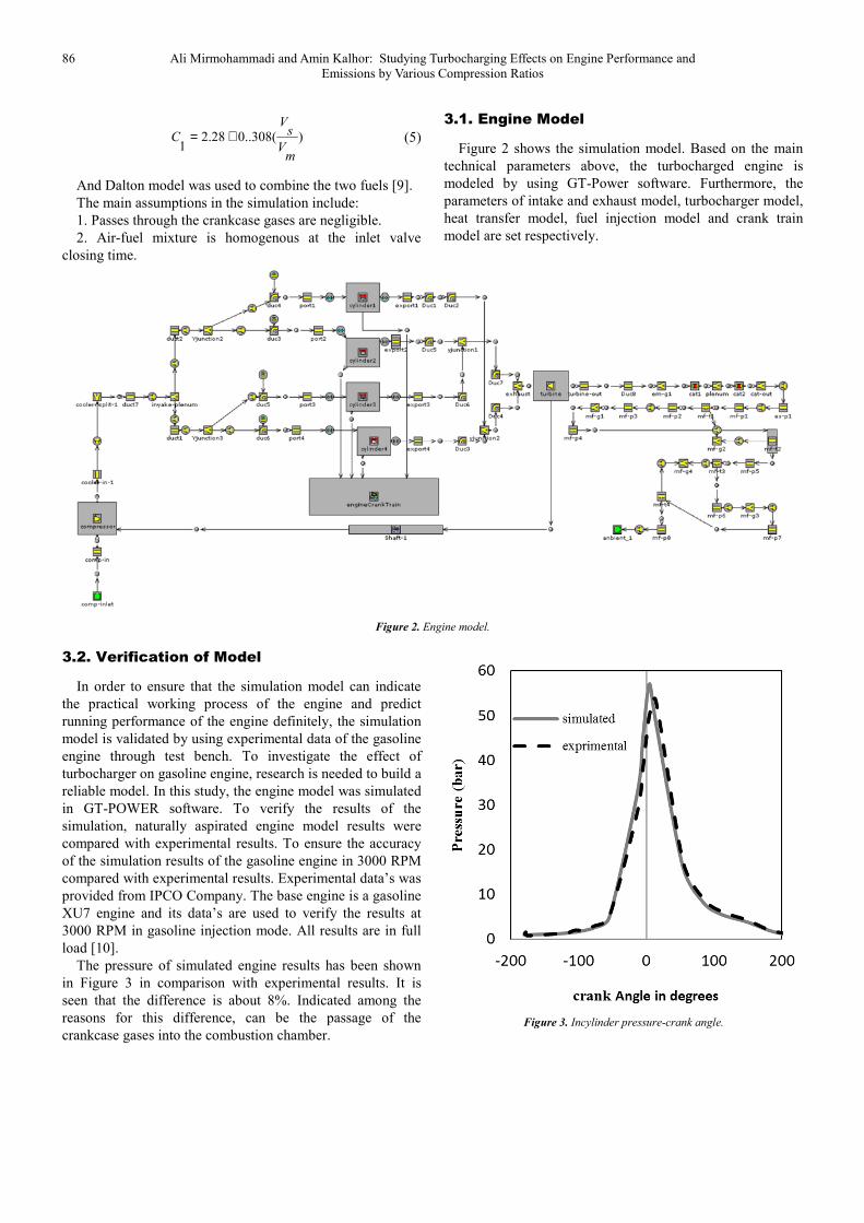
3.1. Engine Model
Figure 2 shows the simulation model. Based on the main
technical parameters above, the turbocharged engine is
modeled by using GT-Power software. Furthermore, the
parameters of intake and exhaust model, turbocharger model,
heat transfer model, fuel injection model and crank train
model are set respectively.
Figure 2. Engine model.
3.2. Verification of Model
In order to ensure that the simulation model can indicate
the practical working process of the engine and predict
running performance of the engine definitely, the simulation
model is validated by using experimental data of the gasoline
engine through test bench. To investigate the effect of
turbocharger on gasoline engine, research is needed to build a
reliable model. In this study, the engine model was simulated
in GT-POWER software. To verify the results of the
simulation, naturally aspirated engine model results were
compared with experimental results. To ensure the accuracy
of the simulation results of the gasoline engine in 3000 RPM
compared with experimental results. Experimental data’s was
provided from IPCO Company. The base engine is a gasoline
XU7 engine and its data’s are used to verify the results at
3000 RPM in gasoline injection mode. All results are in full
load [10].
The pressure of simulated engine results has been shown
in Figure 3 in comparison with experimental results. It is
seen that the difference is about 8%. Indicated among the
reasons for this difference, can be the passage of the
crankcase gases into the combustion chamber.
Figure 3. Incylinder pressure-crank angle.
American Journal of Energy and Power Engineering 2017; 4(6): 84-88 87
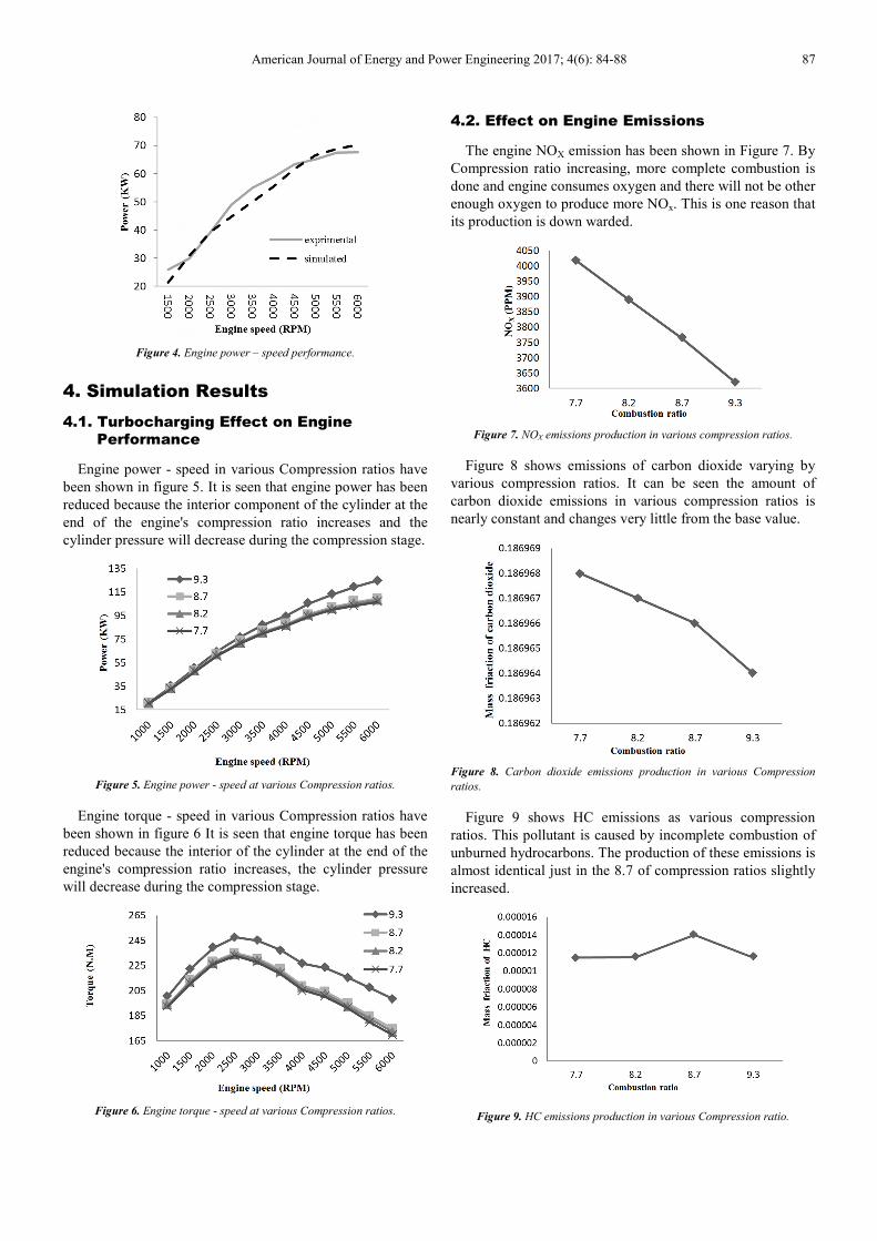
Figure 4. Engine power – speed performance.
4. Simulation Results
4.1. Turbocharging Effect on Engine
Performance
Engine power - speed in various Compression ratios have
been shown in figure 5. It is seen that engine power has been
reduced because the interior component of the cylinder at the
end of the engine's compression ratio increases and the
cylinder pressure will decrease during the compression stage.
Figure 5. Engine power - speed at various Compression ratios.
Engine torque - speed in various Compression ratios have
been shown in figure 6 It is seen that engine torque has been
reduced because the interior of the cylinder at the end of the
engine's compression ratio increases, the cylinder pressure
will decrease during the compression stage.
Figure 6. Engine torque - speed at various Compression ratios.
4.2. Effect on Engine Emissions
The engine NOX emission has been shown in Figure 7. By
Compression ratio increasing, more complete combustion is
done and engine consumes oxygen and there will not be other
enough oxygen to produce more NOx. This is one reason that
its production is down warded.
Figure 7. NOX emissions production in various compression ratios.
Figure 8 shows emissions of carbon dioxide varying by
various compression ratios. It can be seen the amount of
carbon dioxide emissions in various compression ratios is
nearly constant and changes very little from the base value.
Figure 8. Carbon dioxide emissions production in various Compression
ratios.
Figure 9 shows HC emissions as various compression
ratios. This pollutant is caused by incomplete combustion of
unburned hydrocarbons. The production of these emissions is
almost identical just in the 8.7 of compression ratios slightly
increased.
Figure 9. HC emissions production in various Compression ratio.
88 Ali Mirmohammadi and Amin Kalhor: Studying Turbocharging Effects on Engine Performance and
Emissions by Various Compression Ratios
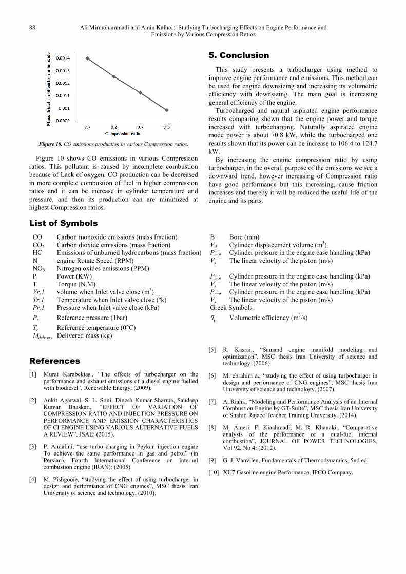
Figure 10. CO emissions production in various Compression ratios.
Figure 10 shows CO emissions in various Compression
ratios. This pollutant is caused by incomplete combustion
because of Lack of oxygen. CO production can be decreased
in more complete combustion of fuel in higher compression
ratios and it can be increase in cylinder temperature and
pressure, and then its production can are minimized at
highest Compression ratios.
5. Conclusion
This study presents a turbocharger using method to
improve engine performance and emissions. This method can
be used for engine downsizing and increasing its volumetric
efficiency with downsizing. The main goal is increasing
general efficiency of the engine.
Turbocharged and natural aspirated engine performance
results comparing shown that the engine power and torque
increased with turbocharging. Naturally aspirated engine
mode power is about 70.8 kW, while the turbocharged one
results shown that its power can be increase to 106.4 to 124.7
kW.
By increasing the engine compression ratio by using
turbocharger, in the overall purpose of the emissions we see a
downward trend, however increasing of Compression ratio
have good performance but this increasing, cause friction
increases and thereby it will be reduced the useful life of the
engine and its parts.
List of Symbols
CO Carbon monoxide emissions (mass fraction) B Bore (mm)
CO2 Carbon dioxide emissions (mass fraction) Vd Cylinder displacement volume (m3)
HC Emissions of unburned hydrocarbons (mass fraction) Pmot Cylinder pressure in the engine case handling (kPa)
N engine Rotate Speed (RPM) Vs The linear velocity of the piston (m/s)
NOX Nitrogen oxides emissions (PPM)
P Power (KW) Pmot Cylinder pressure in the engine case handling (kPa)
T Torque (N.M) Vs The linear velocity of the piston (m/s)
Vr,1 volume when Inlet valve close (m3) Pmot Cylinder pressure in the engine case handling (kPa)
Tr,1 Temperature when Inlet valve close (ºk) Vs The linear velocity of the piston (m/s)
Pr,1 Pressure when Inlet valve close (kPa) Greek Symbols
Pr Reference pressure (1bar) vη
Volumetric efficiency (m
3/s)
Tr Reference temperature (0°C)
Mdelivery Delivered mass (kg)
References
[1] Murat Karabektas., “The effects of turbocharger on the performance and exhaust emissions of a diesel engine fuelled with biodiesel”, Renewable Energy: (2009).
[2] Ankit Agarwal, S. L. Soni, Dinesh Kumar Sharma, Sandeep Kumar Bhaskar., “EFFECT OF VARIATION OF COMPRESSION RATIO AND INJECTION PRESSURE ON PERFORMANCE AND EMISSION CHARACTERISTICS OF CI ENGINE USING VARIOUS ALTERNATIVE FUELS: A REVIEW”, JSAE: (2015).
[3] P. Andalini, “use turbo charging in Peykan injection engine To achieve the same performance in gas and petrol” (in Persian), Fourth International Conference on internal combustion engine (IRAN): (2005).
[4] M. Pishgooie, “studying the effect of using turbocharger in design and performance of CNG engines”, MSC thesis Iran University of science and technology, (2010).
[5] R. Kasrai., “Samand engine manifold modeling and optimization”, MSC thesis Iran University of science and technology. (2006).
[6] M. ebrahim a., “studying the effect of using turbocharger in design and performance of CNG engines”, MSC thesis Iran University of science and technology, (2007).
[7] A. Riahi., “Modeling and Performance Analysis of an Internal Combustion Engine by GT-Suite”, MSC thesis Iran University of Shahid Rajaee Teacher Training University. (2014).
[8] M. Ameri, F. Kiaahmadi, M. R. Khanaki., “Comparative analysis of the performance of a dual-fuel internal combustion”, JOURNAL OF POWER TECHNOLOGIES, Vol 92, No 4: (2012).
[9] G. J. Vanvilen, Fundamentals of Thermodynamics, 5nd ed.
[10] XU7 Gasoline engine Performance, IPCO Company.


