Download - Sunlight controlled lamp!!!

SUNLIGHT CONTROLLED LAMP!!!
NOTION BEHIND S.C.L.Energy conservation is a major topic of discussion
nowadays. To solve the problem of energy wastage, technological experts are putting out great efforts.
Most of the energy usage reports indicate that major part of the energy is used at night hours.
In such a situation, Sunlight Controlled Light Electronics project found to be a very useful and interesting simple DIY electronics project model for street light used at the society.
This is, simple DIY electronics project that can be implemented and demonstrated by the students with ease and also they can convey the need of saving energy.
IDEOLOGY OF CIRCUIT
This mini project can be
demonstrated as model
sunlight controlled
street lights. It can be used in
house also.
It uses a photo
transistor (fitted left
bottom corner of P.C.B.) as sunlight
sensor . As lamp 12 nos. of white
L.E.D. are used.
Unit can be
powered from 12
volts supply a 0-12 volt secondar
y transformer can be used.

Unit requires reflected sunlight for satisfactorily
working.
Do not face sensor directly to bright sunlight . In presence of sunlight sensor
conducts.
Then both transistors stop conduction and
L.E.D’S will not be driven . But in absence
of light transistors conduct and L.E.D’S
are activated.

Unit can be tested by
converting sensor with
fingers.
This project will work with sunlight and light from filament bulb not with tube light or C.F.L.
emitting fluorescent light.
By adjusting 1 MEG present
sensitivity of project can be adjust.
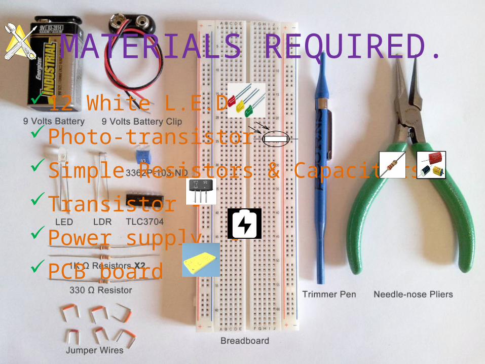
MATERIALS REQUIRED.
12 White L.E.D.-Photo-transistor - Simple Resistors & Capacitors -Transistor -Power supply - PCB board -
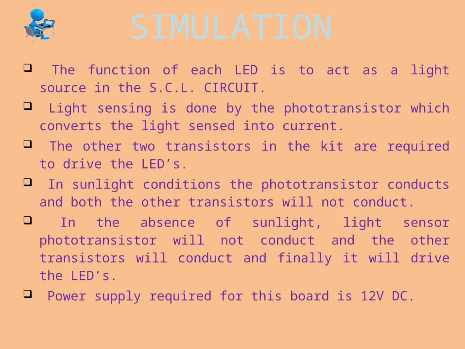
SIMULATION The function of each LED is to act as a light source in the
S.C.L. CIRCUIT. Light sensing is done by the phototransistor which
converts the light sensed into current. The other two transistors in the kit are required to drive
the LED’s. In sunlight conditions the phototransistor conducts and
both the other transistors will not conduct. In the absence of sunlight, light sensor phototransistor
will not conduct and the other transistors will conduct and finally it will drive the LED’s.
Power supply required for this board is 12V DC.

CIRCUIT DIAGRAM

LED EVEN GLOWS IN
DARKNESS!!!RESULT
COST-₨.210/-
UTILIZA
TION
-LIGHT DECOR
-STREET LIGHTS
-STORAGE PURPOSE
-INDUSTRY PURPOSE

THANKYOU


