
Synergy/A
Product Manual
4.1.2015
SYnergy/A

Page 2 of 19
All rights reserved.
to Synel Industries Ltd. Reproduction or use, without express permission of editorial or pictorial content, in any manner is prohibited. No patent liability is
assumed with respect to the use of the information contained herein. While every precaution has been taken in the preparation of this manual, Synel Industries Ltd.
assumes no responsibility for errors or omissions. Neither is any liability assumed for damages resulting from the use of the information contained herein. Pictures in this
manual are for illustration purposes only. SYnergy/A is a trademark of Synel Industries Ltd. All trade names referenced herein are either trademarks or registered
trademarks of their respective companies.
Page 3 of 19
1. Introduction
The SYnergy/A terminal is Synel's latest Linux-based fingerprint biometric device which combines a multi-media color graphic screen with technologically advanced
features for all of your Time and Attendance and Access Control applications.
SYnergy/A utilizes a full version of Java 1.6 as its basic framework for building applications. The device supports Java graphics libraries SWT and SWING and
TSL/SSL communication encryption.
SYnergy/A is compact in size and attractively designed and is also equipped with a built in camera and a speaker for generating various sound effects such as alert
notifications, report confirmation/rejection and other actions or events.
SYnergy/A can be linked to a variety of networks in your organization to complement the systems already in place. SYnergy/A is capable to integrate Time and
Attendance with Access Control.
In addition SYnergy/A has a unique photo-taking function for attendance checking
using a 1.3M pixel color camera that snaps a photo of the user. A personal color photo, personal information and identification time can be displayed on the screen.
SYnergy/A supports TCP/IP networking protocol with optional Power over Ethernet (POE) capability. The clock includes both a protected USB port and an external USB
port.
SYnergy/A is offered with a variety of reader options, including barcode, magnetic
and proximity, and supports 3,000 fingerprint templates (standard configuration) or 10,000 templates (optional) for identification or verification purposes, with fast 1:1
and 1:N matching speed.
Page 4 of 19
2. Technical Specifications
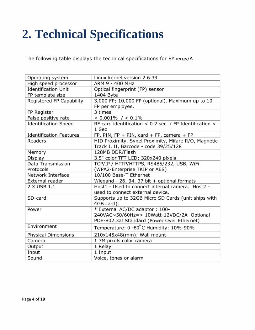
The following table displays the technical specifications for SYnergy/A
Operating system Linux kernel version 2.6.39
High speed processor ARM 9 - 400 MHz
Identification Unit Optical fingerprint (FP) sensor
FP template size 1404 Byte
Registered FP Capability 3,000 FP; 10,000 FP (optional). Maximum up to 10 FP per employee.
FP Register 3 times
False positive rate < 0.001% / < 0.1%
Identification Speed RF card identification < 0.2 sec. / FP Identification < 1 Sec
Identification Features FP, PIN, FP + PIN, card + FP, camera + FP
Readers HID Proximity, Synel Proximity, Mifare R/O, Magnetic
Track I, II, Barcode - code 39/25/128
Memory 128MB DDR/Flash
Display 3.5" color TFT LCD; 320x240 pixels
Data Transmission
Protocols
TCP/IP / HTTP/HTTPS, RS485/232, USB, WiFi
(WPA2-Enterprise TKIP or AES)
Network Interface 10/100 Base-T Ethernet
External reader Wiegand - 26, 34, 37 bit + optional formats
2 X USB 1.1 Host1 - Used to connect internal camera. Host2 -
used to connect external device.
SD-card Supports up to 32GB Micro SD Cards (unit ships with
4GB card).
Power * External AC/DC adaptor : 100-
240VAC~50/60Hz=> 10Watt-12VDC/2A Optional POE-802.3af Standard (Power Over Ethernet)
Environment Temperature: 0 -50o
C Humidity: 10%-90%
Physical Dimensions 210x145x48(mm); Wall mount
Camera 1.3M pixels color camera
Output 1 Relay
Input 1 Input
Sound Voice, tones or alarm
Page 5 of 19
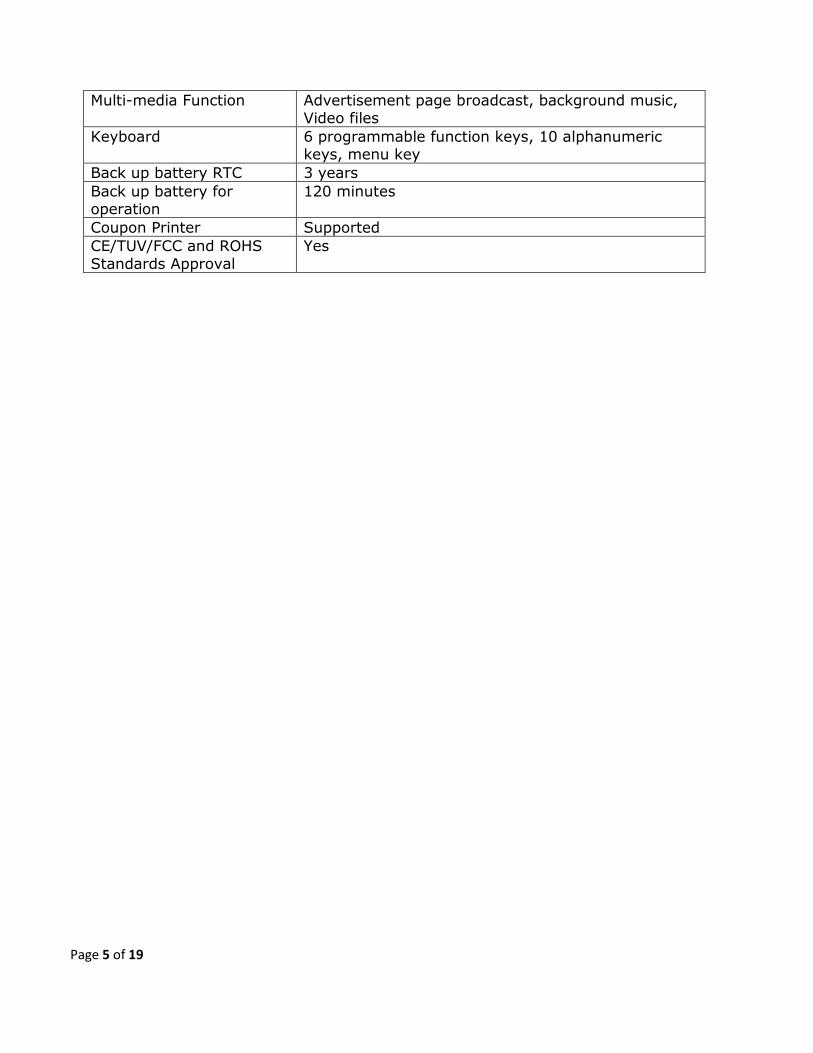
Multi-media Function Advertisement page broadcast, background music, Video files
Keyboard 6 programmable function keys, 10 alphanumeric keys, menu key
Back up battery RTC 3 years
Back up battery for operation
120 minutes
Coupon Printer Supported
CE/TUV/FCC and ROHS
Standards Approval
Yes
Page 6 of 19
2.1 Additional Technical and Interface
Specifications
• 3.5" TFT Color LCD with back light display
• Rechargeable backup battery (three years capacity) for Real Time Clock
• RS-232 and RS-485 communication
• One relay for bell, door control, etc.
• Variable baud rate for serial devices is 9600~115200 bps
• Printer support
2.1.1 Options
Fingerprint readers
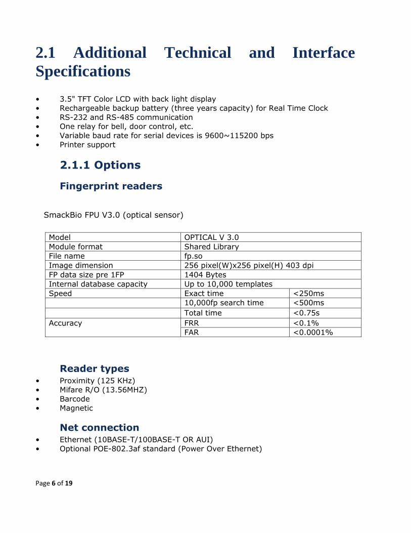
SmackBio FPU V3.0 (optical sensor)
Reader types • Proximity (125 KHz)
• Mifare R/O (13.56MHZ)
• Barcode
• Magnetic
Net connection • Ethernet (10BASE-T/100BASE-T OR AUI)
• Optional POE-802.3af standard (Power Over Ethernet)
Model OPTICAL V 3.0
Module format Shared Library
File name fp.so
Image dimension 256 pixel(W)x256 pixel(H) 403 dpi
FP data size pre 1FP 1404 Bytes
Internal database capacity Up to 10,000 templates
Speed Exact time <250ms
10,000fp search time <500ms
Total time <0.75s
Accuracy FRR <0.1%
FAR <0.0001%

Page 7 of 19
2.1.2 Physical characteristics Front view
Depth 55mm
2.1.3 Power Requirements
• External AC/DC switching adapter, DC 100-240/Volt -> 10Watt-12V/2A Back-up battery-rechargeable included
POE-802.3af (Power Over Ethernet)

Page 8 of 19
2.1.4 Environment
Temperature: 0 -50o
C
Humidity: 10% -90%
2.1.5 Communication and configurations
2.1.5.1 Communication parameters
Communication between the host and terminals is performed under an asynchronous mode. The baud rate is programmable, enabling rates from
9600 to 115000 bps.
2.1.5.2 Multiple terminal configuration
RS-485 communication enables you to connect up to 32 terminals to a single
COM port and/or to extend the cabling distance to up to 1,000 meters (3,280 feet) using 9600 baud via an RS-485 multi-drop line. RS-485 communication uses two wires as opposed to RS-422 communication, which uses four wires.
2.1.5.3 Point to point configuration
A single terminal, equipped with RS-232 communications, can be connected directly to an asynchronous RS-232 port. If RS-232 communication is used,
only one terminal may be connected to each COM port and cabling distances should not exceed 50 meters (160ft).
2.1.5.4 Network connections
The terminal can be connected to one of the following communication networks:
Ethernet - For this type of communication, an IP address is defined for each
terminal, enabling communication with each terminal in TCP/IP protocol.
GPRS - For this type of communication, one SIM card with available GPRS service must be inserted into the terminal.
2.1.5.5 Function configuration
Enter the corresponding menus and set functions you desire.

Page 9 of 19
3. Terminal This terminal is enclosed in a rugged plastic molded casing and is secured to the wall using four screws and a removable panel.
3.1 Front panel
1. On the left side of unit, there are two programmable LED indicator lights with different colors. The functions can be defined by the user.
2. A 3.5" TFT LCD screen 3. The speaker is located to the right of the display. A terminal with an audio decoder
chip can play files in MP3 format with adjustable volume. Additionally, custom sounds can be programmed to play according to preferences. 4. A camera with a wide visible lens to monitor or photograph users.
5. A Biometric fingerprint reader located below camera, supports 3,000 or 10,000 fingerprint templates.
6. Magnetic/bar code card reader (located on the right side of terminal). 7. Internal proximity reader indication. 8. Function keys are located on the left, below the display. F1~F4 keys are
programmable. F1 is also used as the power button of the terminal. IN and OUT keys are two special function keys.
9. A numerical keyboard of sixteen keys, including Enter, Escape, and arrow keys, is located below function keys. They are mainly used for menu operation, input etc.
Page 10 of 19
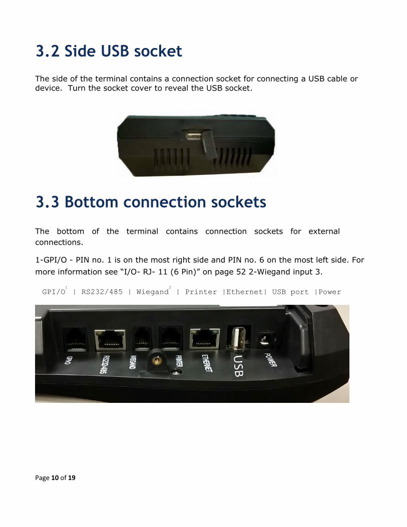
3.2 Side USB socket
The side of the terminal contains a connection socket for connecting a USB cable or
device. Turn the socket cover to reveal the USB socket.
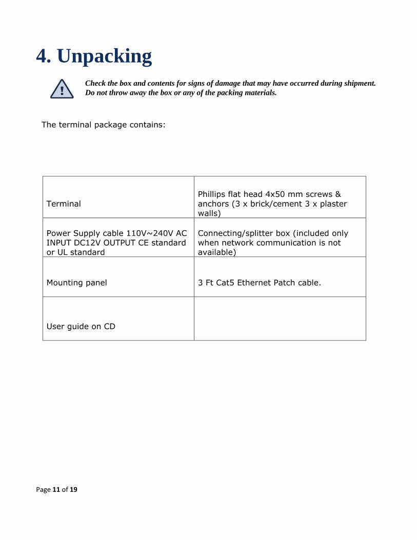
3.3 Bottom connection sockets
The bottom of the terminal contains connection sockets for external
connections.
1-GPI/O - PIN no. 1 is on the most right side and PIN no. 6 on the most left side. For
more information see “I/O- RJ- 11 (6 Pin)” on page 52 2-Wiegand input 3.
GPI/O1
| RS232/485 | Wiegand2
| Printer |Ethernet| USB port |Power
Page 11 of 19
4. Unpacking
Check the box and contents for signs of damage that may have occurred during shipment.
Do not throw away the box or any of the packing materials.
The terminal package contains:
Terminal
Phillips flat head 4x50 mm screws &
anchors (3 x brick/cement 3 x plaster walls)
Power Supply cable 110V~240V AC INPUT DC12V OUTPUT CE standard or UL standard
Connecting/splitter box (included only when network communication is not available)
Mounting panel
3 Ft Cat5 Ethernet Patch cable.
User guide on CD

Page 12 of 19
5. Installation
5.1 Selecting the Terminal Location
General Considerations • The terminal should be placed near an easily accessible power outlet.
• Make sure there is enough space around the terminal for the communication cabling.
• Do not place the communication cable near a source of electromagnetic radiation
or radio interference such as power lines, large machinery, etc.
• If the communication cable is to be wired through the wall, make sure that it is safe to drill a hole at the desired location.
• For best usability the terminal should be mounted at employee eye level. The
recommended height is 140 cm (4’ 7”).
GPRS Considerations
When selecting a place to install a terminal with wireless network
communication (GPRS) you need to consider environmental factors that affect the connection. To find the optimal location:
• Do not install the machine in a strong electromagnetic environment where the RF signal can be effected.
• Avoid locations where the transmission may be blocked by metal obstacles.
• It is best to place the terminal where no high or large buildings are located nearby.
• Do not install the terminal in a location where people gather and linger since they
can block the connection and also as to not expose them to radiation.

Page 13 of 19
5.2 Terminal Wall Mounting
Make sure the unit is not plugged into a power source. If you have already connected your terminal to a PC, disconnect it. You can reconnect it after you have completed mounting the unit.
The terminal contains computer components. It should not be mounted where it will be
exposed to extreme heat or cold, water, steam, violent vibrations, high electromagnetic
radiation including high voltage power lines and electrical equipment.
1) Select a location for the terminal following guidelines specified above.
2) Remove the back mounting panel, if it is connected to the terminal.
A - Screw holes - for screwing the mounting panel in place. B - Entrance for
cables wired from the wall. C - Entrance for cable entering terminal from below.
3) Prepare the wall for mounting by placing the panel on the wall as a
template and mark the place for drilling the holes (A).
4) Drill holes using a 6 mm. (1/4”) drill bit.
Live wires in the vicinity may contain
115V or 220V. Make sure not to drill into any live electric wires. Overlooking this warning
may result in harmful contact with an electrical current.
5) Position the panel so that all of the wires are in place and screw the panel to the wall.
6) Wire all of the cables through the mounting panel and position the electric socket in it’s place in the mounting panel.
7) Connect the communication cables to the terminal. Plug one end of the communication cable into the communication socket of the terminal.
8) Slide the terminal into place.
Page 14 of 19
5.3 Communication Connections
1) Select a location for the connection box. The box must be positioned where
both the communication line and the terminal can be connected to it. The terminal should be placed near the connection box, and must be within the reach of the short
RJ45 cable.
2) Plug the communication cable from the terminal into the connection box.
3) Wire an additional connection for Ethernet.

Page 15 of 19
6. Maintenance This section gives instructions for maintaining the terminal in good working order.
The issues described are:
• Terminal Maintenance
• Calibrating the Real Time Clock (RTC) • Formatting miniSD card
• Clear terminal Flash • Fingerprint sensor cleaning and care
6.1 Do’s and Don’ts
• Install the unit indoor where the temperature can be controlled.
• Keep the unit free of dust and water to avoid a short circuit. • Keep the unit away from magnetic objects and an intense magnetic field.
• If you need to repair the device, please contact the device supplier. • Use original power adapter, supplied with the unit. The original power adapter
has voltage-stabilizing and wave filtering functions, which reduce the influence of power to device.
• Do not open or repair the unit circuit if you are not certified to do so. You may lose your data and seriously damage the unit.
• If the device utilizes the camera, do not install the unit facing the door or window. This may cause the photos to be over exposed. It is better to take
photographs where the light is dimmer. • Do not scratch, hit or press the device with sharp or heavy objects as to not damage the LCD screen, FP Reader and surface.
• Do not shake the device as this can cause damage to inside parts. • Do not format the storage disk without consulting the supplier.

Page 16 of 19
6.2 Terminal Maintenance
6.2.1 Once a month
Badge Readers
• Magnetic badge readers: Use a special cleaning badge made of plastic with a
polishing paper (made of Al2O3, with a grain size of approximately 16 microns) attached to the part of the badge where it contacts the magnetic head. Swipe the
badge once or twice. Excessive cleaning will result in wearing out of the magnetic reader head.
6.2.2 Every six months
General
• Verify that all cables to the terminal ports are well connected.
Keypad and screen
• Keypad and screen: Turn off the device, and clean the keypad and screen with a rag or neutral detergent, then wipe dry.
Battery
• Backup battery: Visually check the battery for leakage. Clean all of the electrical contacts inside the terminal with a contact cleaner.
1) Collect and clear all the data stored in the terminal. 2) Turn off the terminal.
3) Open the terminal. 4) Remove jumper J4. Check the voltage of the memory back-up battery and
make sure it is between 2.8V and 4.2V.
Camera lens • Cleaning the camera lens: If the lens is dusty the dust can be gently blown off.
Clean the display window with a pressure-sensitive adhesive cloth. Do not use water or detergent to clean the lens as it may be damaged. Dry the lens with a soft cloth.

Page 17 of 19
Fingerprint sensor
• The fingerprint sensor is designed to provide years of trouble-free service.
Observance of a few basic maintenance steps will help to ensure a high level of performance over the sensors life span. Several types of sensors exist, such as
optical and silicon based like capacitance or of RF technology. Each type of sensor requires a different cleaning method. Make sure to use the proper cleaning method
for the sensor type in use.
• Cleaning the fingerprint sensor
After repeated use oily deposits from your finger accumulate on the surface of the fingerprint sensor and these can inhibit the functionality of the sensor. It is
recommended that you clean the sensor at least once a week, and also whenever an oily residue is visible on its surface.
Use a clean cotton cloth or tissue paper dampened by water or window
cleaning solution to remove oily deposits.
• Caring for the Fingerprint Sensor
Do not place the fingerprint sensor close to a heat source, such as a radiator or hot
plate. Do not subject the fingerprint sensor to heavy shocks/ vibrations
Do not allow the sensor to come in contact with metallic objects.
• Condition
The sensor can be stored in temperatures ranging from –650
C to +1500
C, and can
operate in temperatures ranging from 00
C to + 600
C.
Sensors should not be exposed to rain or excessive humidity. A sensor can operate
within a range of 5% to 95% humidity (noncondensed).
Other than for cleaning, as instructed above in Cleaning for Fingerprint Sensors, do not bring the sensor in contact with liquids.

Page 18 of 19
7. Connectors and Jumpers
PC communication - RJ-45 (8 pin) with LED indicator Serial
Communication with PC
Yellow led is an indication for TXD of terminal Green led is an indication for RXD of terminal
Printer - RJ- 11 (6 Pin)
Secondary serial communication channel for printer.
Pin Signal Value Remarks
1 NC
2 RS-485 (-TRX) 0-5 Volt
3 RS-485 (+TRX) 0-5 Volt
4 GND
5 RS – 232 (TXD) -/+15Vdc Standard RS-232 levels
6 RS – 232 (RXD) -/+15Vdc Standard RS-232 levels
7/8
Pin Signal Value Remarks
1 NC
2 GND
3 CTS -/+15Vdc Standard RS-232 levels
Printer busy
4 RS - 232 TXD -/+15Vdc
Standard RS-232 levels
Printer
5 RS - 232 RXD -/+15Vdc Standard RS-232 levels
Printer
6 VCC 5 volt

Page 19 of 19
I/O- RJ- 11 (6 Pin)
Synel Americas 16425 N. Pima Road, Suite 190, Scottsdale, Arizona 85260 Phone – 480.374.7700 Fax – 480.682.0935
www.synel-usa.com
Pin Signal Value Remarks
1 Input
2 GND
3 GND
4 Relay COM
5 Relay NC
6 Relay NO


