
3 Edition 0817
AGA
Technical Information middot GB
bull Adjustable test period which can be adapted to different systems
bull Adjustable test instant allows quick system start
bull Maximum safety thanks to self-monitoring electronics
Tightness controls TC
Safety manual for products complying with EN 61508-2
TC middot Edition 0817 2
= To be continued
ContentsTightness controls TC 1Contents 21 Application 411 Application examples 7
111 TC 1V with valVario controls 7112 TC 1C with combination control CGD or CGV 8113 TC 2 with two gas solenoid valves 9114 TC 2 with two gas solenoid valves and one auxiliary valve for discharge 10115 TC 2 with two gas solenoid valves and one auxiliary valve for discharge 11116 TC 2 in a multiple burner system with several valves installed in series 12117 TC 3 in a multiple burner system with several valves installed in series 13118 TC 4 with two gas solenoid valves 14119 TC 4 with two gas solenoid valves and one auxiliary valve for discharge 151110 TC 4 in a multiple burner system with two auxiliary valves for supply and discharge 161111 TC 4 in a multiple burner system with several valves installed in series 17
2 Certification 1821 TC 1 TC 2 TC 3 1822 TC 4 19
3 Function 2031 TC 1 TC 2 TC 3 20
311 Connection diagrams for TC 1 TC 2 20312 Connection diagrams for TC 3 21313 Test procedure for TC 1 TC 2 TC 3 22314 Test instant TC 1 TC 2 TC 3 24315 Test instant for Mode 1 testing before burner run 24316 Test instant for Mode 2 testing after burner run 25317 Test instant for Mode 3 testing before and after burner run 26318 Measurement time tM for TC 1 TC 2 TC 3 27
319 Calculation example for tM 2732 TC 4 28
321 Connection diagram 28322 Test procedure TC 4 29323 TC 4 test instant 31324 Test instant for Mode 1 testing before burner run 31325 Test instant for Mode 2 testing after burner run 32326 Test period tP for TC 4 33327 Calculation example for tP 33
33 Test volume VP for TC 1 TC 2 TC 3 TC 4 3434 Leakage rate QL 3535 Animation 36
4 Selection 3741 TC 1 TC 2 TC 3 37
411 Selection table 37412 Type code 37
42 TC 4 37421 Selection table 37422 Type code 37
5 Project planning information 3851 Selecting the auxiliary valves 3852 Start rate 3953 Installation 39
531 TC 1V for solenoid valves for gas VAS VCx 39532 TC 1C for combination controls CG 39533 TC 2 40534 TC 3 40535 TC 4 40
54 Electrical connection of TC 1 TC 2 4155 Determining the relief line size 41
6 Accessories 4261 Socket 4262 Valve connection cable 4263 External pressure switch for TC 4 42
TC middot Edition 0817 3
7 Technical data 4371 TC 1 TC 2 TC 3 4372 TC 4 4473 Indicators and operating controls 4674 Dimensions 4775 Converting units 4776 Safety-specific characteristic values 48
8 Safety information in accordance with EN 61508-2 for TC 1 TC 2 TC 3 4981 General 49
811 Type of action 49812 Other classifications 49813 Electrical data 49
82 Interfaces 50821 Electrical wiring 50822 Connection terminals 50823 Inputs 50824 Outputs 51
83 SIL and PL for TC 1 TC 2 TC 3 519 Maintenance cycles 5210 Glossary 53101 Tightness control 53102 Valve proving system VPS 53103 Safety interlocks 53104 Diagnostic coverage DC 53105 Operating mode 53106 Hardware fault tolerance HFT 53107 Probability of dangerous failure PFHD 54108 Mean time to dangerous failure MTTFd 54
Feedback 55Contact 55
TC middot Edition 0817 4
TC 1 TC 2 TC 3 TC 4
Application
The tightness control TC checks the fail-safe function of both valves before each start-up or after each shut-down of a system with two safety valves
The aim is to identify an inadmissible leak on one of the gas valves and to prevent burner start The other gas valve continues working properly and takes over the safe shut-off of the gas supply
It is used in industrial thermoprocessing equipment on boilers and on forced draught burners
Standards ISO 13577-2 EN 746-2 and EN 676 stipu-late tightness controls for capacities over 1200 kW (NFPA 86 from 117 kW or 400000 Btuh in conjunc-tion with a visual indicator) Pre-purge of the combus-tion chamber can be dispensed with under certain conditions in accordance with EN 746-2 if a tightness
control is used In this case the system must be vented into a safe area
TC 1V TC 1CTightness control TC 1V can be directly flange-mount-ed to all valVario controls There is only one version for all sizes
TC 1C can be used for combination controls CG 1 to 3 An adapter plate is supplied for installation
1 Application
TC middot Edition 0817 5
Application
TC 2 and TC 4Tightness controls TC 2 and TC 4 can be used with gas solenoid valves of any nominal size which are quick opening or slow opening with start rate It is possible to conduct a tightness test on pneumatically operated or slow opening valves without start rate by using addi-tional auxiliary valves
Slow opening motorized valves VK up to DN 65 which are directly flanged together can also be checked by TC 2 and TC 4 within a temperature range of 0 to 60degC (32 to 140degF)
An adapter plate is provided for installation of the TC 2
TC 3
Tightness control TC 3 is a universal device for quick and slow opening gas solenoid valves of any nominal size as well as for motorized valves The tightness test is carried out with the valves installed in TC 3
TC 4Tightness control TC 4 consists of detection circuitry and can be installed in the control cabinet separately from the system An external pressure switch takes over the mechanical pressure test between the valves Tightness control TC 4 is independent of gas type and inlet pressure pu and can be used for a test period of up to 10 minutes with a large test volume
TC middot Edition 0817 6
Application
TC 1V on a valVario double solenoid valve TC 4 installed separately from the system in a control cabinet
TC middot Edition 0817 7
Application
1 1 Application examplesPZ = Internal pressure sensor of the TC for the compari-
son of inlet pressure pu and interspace pressure pz
pd = Outlet pressure
VP = Test volume
1 1 1 TC 1V with valVario controlsMains voltage = control voltage V1 quick or slow opening valve with start rate V2 pressure regulator with solenoid valve
Tightness control TC 1V checks gas solenoid valves V1 and V2 and the pipe between the valves for tightness If both valves are tight the TC forwards the OK enable signal to the automatic burner control unit GFA This opens valves V1 and V2 simultaneously The burner starts
V1 V2
VADVAS
PZ
pu pz
VP
TC 1V
pu2
TC 1V
OK
9
V2V1
GFA
TC middot Edition 0817 8
Application
1 1 2 TC 1C with combination control CG D or CG VMains voltage = control voltage V1 and V2 quick opening valves
TC 1C is directly flange-mounted to combination con-trol CGD or CGV and checks gas solenoid valves V1 and V2 in the combination control for tightness
Once the tightness test has been carried out success-fully the tightness control forwards the OK enable signal to the automatic burner control unit GFA This opens valves V1 and V2 in the combination control CG simultaneously The burner starts
V1
pu2
CG
V1 V2
PZ
pu pz
TC 1C
PZ
VP
TC 1C
9
OK
GFA
TC middot Edition 0817 9
Application
1 1 3 TC 2 with two gas solenoid valvesMains voltage = control voltage V1 and V2 quick or slow opening valves with start rate
TC 2 checks gas solenoid valves V1 and V2 and the pipe between the valves for tightness If both valves are tight the TC forwards the OK enable signal to the automatic burner control unit GFA This opens valves V1 and V2 simultaneously The burner starts
V2V1
pu2
V1 V2
PZ
pu pz
TC 2
VP
TC 2
9
OK
GFA
TC middot Edition 0817 10
Application
1 1 4 TC 2 with two gas solenoid valves and one auxiliary valve for dischargeMains voltage = control voltage V1 and V2 quick or slow opening valves with start rate V3 quick or slow opening valve with start rate nominal size is dependent on test volume VP and inlet pres-sure pu see page 38 (Project planning information) but is at least DN 15
TC 2 checks gas solenoid valves V1 V2 the auxiliary valve V3 and the pipe between the valves for tightness It must be ensured that the interspace pz is vented dur-ing the 3-second opening time This is not guaranteed by the gas pressure regulator downstream of V2 A relief line is thus used to discharge the test volume VP safely into the combustion chamber or into a safe area Auxil-iary valve V3 can also be used as a pilot gas valve Since valve V2 remains closed during the test it can also be a slow opening motorized valve VK Once the tightness test has been carried out success-fully the tightness control forwards the OK enable sig-nal to the automatic burner control unit GFA The GFA opens the gas solenoid valves V1 and V2 simultane-ously The burner starts
GFAV1
pu2
V1 V2
PZ
pu pz
TC 2V3
VP
TC 2
OK
V2
9
V3
TC middot Edition 0817 11
Application
1 1 5 TC 2 with two gas solenoid valves and one auxiliary valve for dischargeMains voltage = control voltage V1 quick or slow opening valve with start rate V2 any V3 quick opening nominal size is dependent on test volume VP and inlet pressure pu see page 38 (Pro-ject planning information) but is at least DN 15
TC 2 checks gas solenoid valves V1 V2 the auxiliary valve V3 and the pipe between the valves for tightness If all the gas solenoid valves are tight the tightness control forwards the OK enable signal to the automatic burner control unit GFA The GFA opens the gas so-lenoid valves V1 and V2 simultaneously The burner starts A relief line is used to discharge the test volume VP into a safe area Thanks to the installed auxiliary valve V3 valve V2 can also be a slow opening motorized valve VK
pu2
V1 V2
PZ
pu pz
TC 2
V3
VP
GFAV1
TC 2
OK
9
V3
V2
TC middot Edition 0817 12
Application
1 1 6 TC 2 in a multiple burner system with several valves installed in seriesMains voltage = control voltage
V3 and V4 quick opening nominal size is dependent on test volume VP and inlet pressure pu see page 38 (Project planning information) but is at least DN 15
When using slow opening main valves (V1 and V2) aux-iliary valves (V3 and V4) must be used for the supply and discharge of the test volume VP TC 2 checks the central shut-off valve V1 the gas so-lenoid valve V2 the auxiliary valves V3 and V4 and the pipe between these valves for tightness Valve V2 can only be checked for tightness when the pressure downstream of V2 approximately corresponds to the atmospheric pressure and the volume down-stream of valve V2 is 5 x VP The gas solenoid valve VAS and the pressure switch DGVAS are used to relieve the pressure The pressure switch must be adjusted in such a way so that enough pressure is relieved and no air can get into the pipework Once the tightness test has been carried out success-fully TC 2 opens the main valves V1 and V2 with the OK enable signal and enables the downstream burner control units
V4V3
pu2
V1 V2
PZ
pu pz
TC 2
K1
DG VAS
VAS
V3
V4
VAS
DG
VAS
PZ
VP
TC 2
OK
K1
V1
V2
9
TC middot Edition 0817 13
Application
1 1 7 TC 3 in a multiple burner system with several valves installed in seriesV1 and V2 any
TC 3 checks slow opening main valves V1 and V2 and the pipe between these valves for tightness The test volume VP is supplied and discharged via the TC 3 auxiliary valves Valve V2 can only be checked for tightness when the pressure downstream of V2 approximately corresponds to the atmospheric pressure and the volume down-stream of valve V2 is 5 x VP The gas solenoid valve VAS and the pressure switch DGVAS are used to relieve the pressure The pressure switch must be adjusted in such a way so that enough pressure is relieved and no air can get into the pipework
Once the tightness test has been carried out success-fully TC 3 opens the main valves V1 and V2 with the OK enable signal and enables the downstream burner control units
K1
DG VAS
VASVA
S
DG
VAS
PZ
TC 3
OK
9
V1 V2
pu pz
VP
PZ
TC 3
pu2
pu pd
K1
V1
V2
TC middot Edition 0817 14
Application
1 1 8 TC 4 with two gas solenoid valvesV1 and V2 quick or slow opening valves with start rate
TC 4 checks gas solenoid valves V1 and V2 and the pipe between the valves for tightness The external pressure switch DG monitors the pressure between the two valves Once the tightness test has been carried out success-fully TC 4 forwards the OK enable signal to the auto-matic burner control unit GFA The GFA opens the gas solenoid valves V1 and V2 simultaneously The burner starts
1 2 3 4 5 6 7 8 9 10 111213
OK
L1(+)N(-)
TC 4
pu2
V1
V1
V2
V2
pu
PZ
TC 4
pz
VP
PZ
DG
GFA
TC middot Edition 0817 15
Application
1 1 9 TC 4 with two gas solenoid valves and one auxiliary valve for dischargeV1 quick or slow opening valve with start rate V2 any V3 quick opening nominal size is dependent on test
volume VP and inlet pressure pu see page 38 (Project planning information) but is at least DN 15
TC 4 checks gas solenoid valves V1 V2 the auxiliary valve V3 and the pipe between the valves for tightness It must be ensured that the interspace pz is vented dur-ing the 2-second opening time This is not guaranteed by the gas pressure regulator downstream of V2 A relief line is thus used to discharge the test volume VP safely into the combustion chamber or into a safe area Since valve V2 remains closed during the test it can also be a slow opening motorized valve VK If all the gas solenoid valves are tight TC 4 forwards the OK enable signal to the automatic burner control unit GFA The GFA opens the gas solenoid valves V1 and V2 simultaneously The burner starts
1 2 3 4 5 6 7 8 9 10 111213
OK
L1(+)N(-)
TC 4
V1
V3V2
V1 V2
pu pz
V3pu2
PZDG
TC 4
ϑ
VP
PZ
GFA
TC middot Edition 0817 16
Application
1 1 10 TC 4 in a multiple burner system with two auxiliary valves for supply and dischargeV1 any V2 and V3 quick opening nominal size is dependent on test volume VP and inlet pressure pu see page 38 (Project planning information) but is at least DN 15
TC 4 checks the central shut-off valve V1 the auxiliary valves V2 and V3 the burner valves and the pipe be-tween these valves for tightness The test volume VP is supplied via the auxiliary valve V3 The external pressure switch DG monitors the pressure between the gas solenoid valves V1 V2 and the burner valves Once the tightness test has been carried out success-fully TC 4 opens gas solenoid valve V1 The TC forwards the OK enable signal simultaneously to the automatic burner control units for the burner valves The burner valves open and the burners start Thanks to the relief line and auxiliary valve V2 the test volume VP is discharged into a safe area or into the combustion chamber
pz
pu2
OK
L1(+)N(-)
TC 4
1 2 3 4 5 6 7 8 9 10 111213
V1
pu
V3
V2
TC 4
V3
V2V1
PZ
VP
DG
PZ
TC middot Edition 0817 17
Application
1 1 11 TC 4 in a multiple burner system with several valves installed in seriesV1 and V2 quick or slow opening valves with start rate
Tightness control TC 4 checks the central shut-off valve V1 the gas solenoid valve V2 and the pipe between these valves for tightness Valve V2 can only be checked for tightness when the pressure downstream of V2 approximately corresponds to the atmospheric pressure The gas solenoid valve VAS and the pressure switch DGVAS are used to relieve the pressure The pressure switch must be adjusted in such a way so that enough pressure is relieved and no air can get into the pipework After the thermostatstart-up signal ϑ has been applied first DGVAS is checked If the pressure downstream of V2 is correct the VAS closes and the tightness test is started Once the tightness test has been carried out success-fully TC 4 opens the main valves V1 and V2 with the OK enable signal and enables the downstream burner control units
pu2
OK
L1(+)N(-)
TC 4
K1
k1
VAS
1 2 3 4 5 6 7 8 9 10 111213
DGVASk1
V1 V2
pu
TC 4
V1
V2
VAS
PZ
DG
VAS
pz
VP
PZ
PZDG
TC middot Edition 0817 18
Certification
2 CertificationCertificates ndash see Docuthek
2 1 TC 1 TC 2 TC 3
Certified pursuant to SIL
For systems up to SIL 3 pursuant to EN 61508
Pursuant to EN ISO 13849-1 Table 4 TC 1 TC 2 and TC 3 can be used up to PL e
EU certified pursuant to
Directives
ndash Gas Appliances Directive 2009142EC (valid until 20 April 2018) in conjunction with EN 1643 EN 60730 and EN 61000-6-2
ndash Low Voltage Directive (201435EU)
ndash EMC Directive (201430EU)
Regulation
ndash Gas Appliances Regulation (EU) 2016426 (valid from 21 April 2018)
TC middot Edition 0817 19
Certification
2 2 TC 4
EU certified pursuant to
ndash Tightness control TC complies with the requirements set out in section 52234 of EN 746-2 It achieves a safety level equivalent to EN 1643 Scan of the Declaration of conformity (D GB) ndash see Docuthek
FM approved230 V
Factory Mutual Research Class 7400 and 7411 Safety overpressure slam shut valves Designed for applica-tions pursuant to NFPA 85 and NFPA 86 wwwapprov-alguidecom
UL listedUSA and Canada
120 V
Standard UL 353 Limit control Link to Underwriters Laboratories ndashwwwulcom Tools (at the bottom of the page) Online Certifications Directory
Canadian Standards Association CSA-C222 No 24
AGA approved
AGA
Australian Gas Association Approval No 4581 httpwwwagaasnauproduct_directory
Eurasian Customs Union
The product TC 4 meets the technical specifications of the Eurasian Customs Union
TC middot Edition 0817 20
Function
3 Function3 1 TC 1 TC 2 TC 3
3 1 1 Connection diagrams for TC 1 TC 2
TC 1 WW TC 1 QQ TC 1 KK TC 2 WW TC 2 QQ or TC 2 KKMains voltage = control voltage 24 V DC 120 V AC or 230 V AC see page 37 (Selection)
OK
V2
TC 1 TC 2
V1
V1 = inlet valve V2 = outlet valve
Remote reset by applying control voltage to terminal 11 or via a floating contact between terminals 8 and 11
TC 1 WK TC 1 QK TC 2 WK or TC 2 QK
Mains voltage 120 V AC or 230 V AC Control voltage 24 V DC see page 37 (Selection)
TC 1 TC 2
V2V1
OK
V1 = inlet valve V2 = outlet valve
Remote reset by applying control voltage (+24 V) to ter-minal 11
TC middot Edition 0817 21
Function
3 1 2 Connection diagrams for TC 3
TC 3 WW TC 3 QQ or TC 3 KKMains voltage = control voltage 24 V DC 120 V AC or 230 V AC see page 37 (Selection)
OK
TC 3
Remote reset by applying control voltage to terminal 11 or via a floating contact between terminals 8 and 11
TC 3 WK or TC 3 QKMains voltage 120 V AC or 230 V AC Control voltage 24 V DC see page 37 (Selection)
OK
TC 3
Remote reset by applying control voltage (+24 V) to ter-minal 11
TC middot Edition 0817 22
Function
3 1 3 Test procedure for TC 1 TC 2 TC 3Depending on the pressure between the valves pz the tightness control TC carries out a check using test pro-cedure A or B If pressure pz gt pu2 program A starts If pressure pz lt pu2 program B starts see page 23 (Test procedure B)
Test procedure AValve V1 opens for the opening time tL = 3 s and closes again During the measurement time tM the tightness control checks the pressure pz between the valves
If pressure pz is less than half the inlet pressure pu2 valve V2 is leaking
If pressure pz is greater than half the inlet pressure pu2 valve V2 is tight Valve V2 is opened for the set opening time tL V2 closes again
During the measurement time tM the tightness control checks the pressure pz between the valves
If pressure pz is greater than half the inlet pressure pu2 valve V1 is leaking
If pressure pz is less than half the inlet pressure pu2 valve V1 is tight
The tightness test can only be performed if the pres-sure downstream of V2 is around atmospheric pressure
tL = 3 s
tM
ndash
ndash+
+
+ ndash
tM
pz gtpu2
V1
V1
V1
pz gtpu2
V2 OK V2 V1 OK
V2
V2
tL = 3 s
tL = 3 s
tM
+
ndash
tM
pz gtpu2+
ndash
V2
V2
V2
pz gtpu2
V1 OK V1 V2 OK
V1
V1
tL = 3 s
pu pz
pz gtpu2
TEST
V1 V2
Test procedure A Test procedure B
START
TC middot Edition 0817 23
Function
Test procedure BValve V2 opens for the opening time tL = 3 s and closes again During the measurement time tM the tightness control checks the pressure pz between the valves
If pressure pz gt pu2 valve V1 is leaking
If pressure pz lt pu2 valve V1 is tight Valve V1 is opened for the set opening time tL V1 closes again
During the measurement time tM the tightness control checks the pressure pz between the valves
If pressure pz lt pu2 valve V2 is leaking
If pressure pz gt pu2 valve V2 is tight
The tightness test can only be performed if the pres-sure downstream of V2 is around atmospheric pressure and the volume downstream of V2 is at least 5 x higher than the volume between the valves
If the power fails briefly during the test or during opera-tion the TC will restart in accordance with the test pro-cedure described above
If there is a fault message the fault is displayed again after a power failure
tL = 3 s
tM
ndash
ndash+
+
+ ndash
tM
pz gtpu2
V1
V1
V1
pz gtpu2
V2 OK V2 V1 OK
V2
V2
tL = 3 s
tL = 3 s
tM
+
ndash
tM
pz gtpu2+
ndash
V2
V2
V2
pz gtpu2
V1 OK V1 V2 OK
V1
V1
tL = 3 s
pu pz
pz gtpu2
TEST
V1 V2
Test procedure A Test procedure B
START
TC middot Edition 0817 24
Function
3 1 4 Test instant TC 1 TC 2 TC 3Two DIP switches are used to determine whether the tightness of the gas solenoid valves is to be checked before burner run after burner run or before and after burner run
3 1 5 Test instant for Mode 1 testing before burner run
Mode 1 = factory setting
tM
5s10s15s20s25s30s
Mode 1
Mains voltage L1 is switched on In the case of untest-ed valves the LEDs 1
2
Power
and 1
2
Power
are yellow
The tightness test starts with incoming thermostatstart-up signal ϑ If the valves are tight the LEDs 1
2
Power
and
1
2
Power
are green Once the safety interlock input sig-nal
OK
V1
V2
is active the OK enable signal is forwarded to the automatic burner control unit
The tightness test is valid for up to 24 hours If the safe-ty interlock input signal
OK
V1
V2
is not connected during this time the test is started again with the application of the safety interlock input signal Once the test has been completed successfully the OK enable signal is issued
L1 (+)ϑ
TEST
OK
Mode 1
t
110
612
t
L1 (+)ϑ
TEST
OK
110
12
12
12
tp
donrsquot-care
tp
5
6
5
V1 leakingV2 leaking
TEST
LeaksIf the tightness control TC detects a leak on one of the two valves the red LED lights up for a fault on valve V1
1
2
Power
or valve V2 1
2
Power
A fault is signalled externally eg by switching on a buzzer or a warning light
L1 (+)ϑ
TEST
OK
Mode 1
t
110
612
t
L1 (+)ϑ
TEST
OK
110
12
12
12
tp
donrsquot-care
tp
5
6
5
V1 leakingV2 leaking
TEST
TC middot Edition 0817 25
Function
3 1 6 Test instant for Mode 2 testing after burner run
tM
5s10s15s20s25s30s
Mode 2
The tightness test after burner run begins as soon as the burner is switched off
To ensure that the valves are checked for tightness once before starting up the system the tightness test runs when the mains voltage (L1) is applied or after a reset If the valves are tight the LEDs 1
2
Power
and 1
2
Power
are green The OK enable signal is not forwarded to the automatic burner control unit until the thermostatstart-up signal ϑ and the safety interlock input signal
OK
V1
V2
have been applied
The tightness test after burner run starts when the thermostatstart-up signal ϑ drops The OK enable sig-nal is only forwarded to the automatic burner control unit again once the thermostatstart-up signal ϑ and the safety interlock input signal
OK
V1
V2
have been re-applied
The tightness test is valid for 24 hours If the thermo-statstart-up signal ϑ and the safety interlock input signal
OK
V1
V2
are connected during this time a new tight-ness test must not be carried out before burner run and the OK enable signal is set However if the 24 hours have elapsed a new tightness test is carried out before burner run
L1 (+)ϑ
TEST
OK
Mode 2
t
t
110
612
L1 (+)ϑ
TEST
OK
110
612
12
12
TEST
donrsquot-care5
tp
tp
tp
5
V1 undichtV2 undicht
LeaksIf the tightness control TC detects a leak on one of the two valves the red LED lights up for a fault on valve V1
1
2
Power
or valve V2 1
2
Power
A fault is signalled externally eg by switching on a buzzer or a warning light
L1 (+)ϑ
TEST
OK
Mode 2
t
t
110
612
L1 (+)ϑ
TEST
OK
110
612
12
12
TEST
donrsquot-care5
tp
tp
tp
5
V1 leakingV2 leaking
TC middot Edition 0817 26
Function
3 1 7 Test instant for Mode 3 testing before and after burner run
tM
5s10s15s20s25s30s
Mode 3
The first test is carried out before burner run (as with Mode 1) The tightness test starts with incoming thermostatstart-up signal ϑ If the valves are tight the LEDs 1
2
Power
and
1
2
Power
are green Once the safety interlock input signal
OK
V1
V2
is active the OK enable signal is forwarded to the automatic burner control unit see page 24 (Test instant for Mode 1 testing before burner run)
The second test is carried out after burner run (as with Mode 2) The tightness test after burner run starts when the thermostatstart-up signal ϑ drops see page 25 (Test instant for Mode 2 testing after burner run)
TC middot Edition 0817 27
Function
3 1 8 Measurement time tM for TC 1 TC 2 TC 3The sensitivity of the tightness control TC can be ad-justed by adapting the measurement time tM for each individual system The longer the measurement time tM the greater the sensitivity of the tightness control The longer the measurement time the smaller the leakage rate at which a safety shut-downfault lock-out is trig-gered
tM
5s10s15s20s25s30s
The measurement time can be set with a jumper to be-tween 5 s and max 30 s 30 s = factory setting
Without jumper no function The 1
2
Power
LED is permanently red
The required measurement time tM is calculated from Qmax = max flow rate [m3h] QL = leakage rate [lh] = Qmax [m3h] x 01 see page 35 (Leakage rate QL) pu = inlet pressure [mbar] VP = test volume [l] see page 34 (Test volume VP for TC 1 TC 2 TC 3 TC 4)
Converting units see wwwadlatusorg
Measurement time tM
tM [s] = 25 x pu [mbar] x VP [l]
QL [lh]
For all combination controls CG the measurement time tM for TC 1C is 5 s
Test period tPThe entire test period is calculated from the measure-ment time tM for both valves and the fixed opening time tL of both valves
tP [s] = 2 x tL + 2 x tM
3 1 9 Calculation example for tM See Calculating measurement time tM of tightness controls TC 1 TC 2 TC 3
TC middot Edition 0817 28
Function
3 2 TC 4
3 2 1 Connection diagramFault signalling contact on terminals 8 and 9 signalling contact (not internally fused) max 1 A for 220240 V (high voltage 264 V) max 2 A for 120 V
Connect the NO contact on the pressure switch to ter-minals 6 and 7
1 2 3 4 5 6 7 8 9 10 11 12 13
L1(+)V1L1(+)V2
OK
max 1 A264 V
ϑ
L1(+)N(-)
pu2
5 AT
TEST OK
V1
1 2
V2
PZ
TC middot Edition 0817 29
Function
3 2 2 Test procedure TC 4The TEST starts with the waiting time tW Once the wait-ing time has elapsed the tightness control TC checks the pressure between the inlet valve V1 and the outlet valve V2
Depending on the pressure between the valves pz the tightness control TC carries out a check using test pro-cedure A or B If pressure pz gt pu2 program A starts If pressure pz lt pu2 program B starts see page 30 (Test procedure B)
+ ndash
V2 OK V1 OK
tL = 2 s
tM
+
ndash
tM
pz gtpu2+
ndash
V2
V2
V2
pz gtpu2
V1 OK V1 V2 OK
V1
V1
tL = 2 s
pu
pu
pz
tW
pz gtpu2
TEST
V1 V2
PZ2
Test procedure A Test procedure B
START
Test procedure AIf pressure pz is greater than half the inlet pressure pu2 valve V2 is tight Valve V2 is opened for the opening time tL = 2 s V2 closes again
During the measurement time tM the tightness control checks the pressure pz between the valves
If pressure pz is greater than half the inlet pressure pu2 valve V1 is leaking
If pressure pz is less than half the inlet pressure pu2 valve V1 is tight
The tightness test can only be performed if the pres-sure downstream of V2 is around atmospheric pressure
+ ndash
V2 OK V1 OK
tL = 2 s
tM
+
ndash
tM
pz gtpu2+
ndash
V2
V2
V2
pz gtpu2
V1 OK V1 V2 OK
V1
V1
tL = 2 s
pu
pu
pz
tW
pz gtpu2
TEST
V1 V2
PZ2
Test procedure A Test procedure B
START
TC middot Edition 0817 30
Function
Test procedure BIf pressure pz lt pu2 valve V1 is tight Valve V1 is opened for the opening time tL = 2 s V1 closes again During the measurement time tM the tightness control checks the pressure pz between the valves
If pressure pz lt pu2 valve V2 is leaking
If pressure pz gt pu2 valve V2 is tight
The tightness test can only be performed if the pres-sure downstream of V2 is around atmospheric pressure and the volume downstream of V2 is at least 5 x higher than the volume between the valves
The tightness control TC runs program A or Bdepend-ing on the initial situation Both valves are checked for tightness respectively but only one valve is opened at a time
During the test the TC also checks their fail-safe opera-tion
After a brief power failure during the tightness test or operation the TC restarts automatically
+ ndash
V2 OK V1 OK
tL = 2 s
tM
+
ndash
tM
pz gtpu2+
ndash
V2
V2
V2
pz gtpu2
V1 OK V1 V2 OK
V1
V1
tL = 2 s
pu
pu
pz
tW
pz gtpu2
TEST
V1 V2
PZ2
Test procedure A Test procedure B
START
TC middot Edition 0817 31
Function
3 2 3 TC 4 test instantA jumper (on the left in the picture) is used to determine whether the tightness of the gas solenoid valves is to be checked before or after burner run
The test period tP is set using the second jumper (on the right in the picture) see page 33 (Test period tP for TC 4)
3 2 4 Test instant for Mode 1 testing before burner run
Mode 1 = factory setting Mains voltage L1 is switched on The tightness test starts with incomingthermostatstart-up signal ϑ If the valves are tight the green OK LED lights up The OK en-able signal is forwarded to the automatic burner control unit
L1 (+)ϑ
TESTOK
OK
tp
ϑTEST
OK12
OK
1 2Mode
t
L1 (+)15
67
15
67
t
tp
TEST
12
V1 undichtV2 undicht
If the tightness control TC detects a leak on one of the two valves the red LED lights up for a fault on valve V1
1 or valve V2 2 A fault is signalled externally eg by switching on a buzzer or a warning light
L1 (+)ϑ
TESTOK
OK
tp
ϑTEST
OK12
OK
1 2Mode
t
L1 (+)15
67
15
67
t
tp
TEST
12
V1 leakingV2 leaking
TC middot Edition 0817 32
Function
3 2 5 Test instant for Mode 2 testing after burner runIf the jumper is set to Mode 2 the tightness test after burner run begins as soon as the burner is switched off
To ensure that the valves are checked for tightness once before starting up the system the tightness test runs when the mains voltage (L1) is applied If the valves are tight the green OK LED lights up The OK enable signal is not forwarded to the automatic burner control unit until the thermostatstart-up signal ϑ has been applied
The tightness test after burner run starts when the thermostatstart-up signal ϑ drops The OK enable signal is not forwarded to the automatic burner control unit again until the thermostatstart-up signal ϑ has been re-applied
ϑTEST
OK
OK
ϑTEST
OK
OK
L1 (+)
L1 (+)
15
67
15
67
12
12
tp
t
t
tp
1 2ModeTEST
V1 undichtV2 undicht
If the tightness control TC detects a leak on one of the two valves the red LED lights up for a fault on valve V1
1 or valve V2 2 A fault is signalled externally eg by switching on a buzzer or a warning light
ϑTEST
OK
OK
ϑTEST
OK
OK
L1 (+)
L1 (+)
15
67
15
67
12
12
tp
t
t
tp
1 2ModeTEST
V1 leakingV2 leaking
TC middot Edition 0817 33
Function
3 2 6 Test period tP for TC 4The sensitivity of the tightness control TC can be ad-justed by adapting the test period tP for each individual system The longer the test period tP the greater the sensitivity of the TC The longer the test period the smaller the leakage rate at which a safety shut-downfault lock-out is triggered
The test period is set using the second jumper (on the right in the picture)
The test period tP can be adjusted in intervals TC 410-1 10 s to max 60 s 10 s = factory setting 60 s = without jumper
TC 410-10 100 s to max 600 s 100 s = factory setting 600 s = without jumper
The required test period tP is calculated from
Qmax = max flow rate [m3h] QL = leakage rate [lh] = Qmax [m3h] x 01 see page 35 (Leakage rate QL) pu = inlet pressure [mbar] VP = test volume [l] see page 34 (Test volume VP for TC 1 TC 2 TC 3 TC 4) Converting units see wwwadlatusorg
tP [s] = 4thinspx ( pu [mbar] x VP [l]thinsp + 1 s)QL [lh]
3 2 7 Calculation example for tP See Calculating test period tP of tightness control TC 4
TC middot Edition 0817 34
Function
3 3 Test volume VP for TC 1 TC 2 TC 3 TC 4
Test volume VP is calculated from the valve volume VV added to the volume of the pipe VR for each additional metre in length L
L VP = VV + L x VR
VP
V1
V2
The tightness control TC requires a minimum start rate in order to carry out tightness tests on slow opening valves see page 38 (Project planning information)
ValvesValve
volume VV [l]
Nominal sizeDN
Pipe volume VR [lm]
VG 10 001 10 01VG 15 007 15 02VG 20 012 20 03VG 25 02 25 05VG 40VK 40 07 40 13VG 50VK 50 12 50 2VG 65VK 65 2 65 33VG 80VK 80 4 80 5VG 100VK 100 83 100 79VK 125 136 125 123VK 150 20 150 177VK 200 42 200 314VK 250 66 250 49VAS 1 008VAS 2 032VAS 3 068VAS 6 137VAS 7 204VAS 8 334VAS 9 541VCS 1 005VCS 2 018VCS 3 039VCS 6 111VCS 7 140VCS 8 282VCS 9 434
TC middot Edition 0817 35
Function
3 4 Leakage rate QL If no leakage rate is specified we recommend the max possible test periodmeasurement time is set
It is possible to check a specific leakage rate QL using the TC Within the scope of the European Union the maximum leakage rate QL is 01 of the maximum flow rate Q(n) max [m3h]
Leakage rate QL [lh] = Q(n) max [m3h] x 10001000
If a small leakage rate QL is to be detected a long test periodmeasurement time must be set
TC middot Edition 0817 36
Function
3 5 Animation
The interactive animation shows the function of the tightness control TC 4
Click on the picture The animation can be controlled using the control bar at the bottom of the window (as on a DVD player)
To play the animation you will need Adobe Reader 7 or a newer version If you do not have Adobe Reader on your system you can download it from the Internet
If the animation does not start to play you can down-load it from the document library (Docuthek) as an in-dependent application
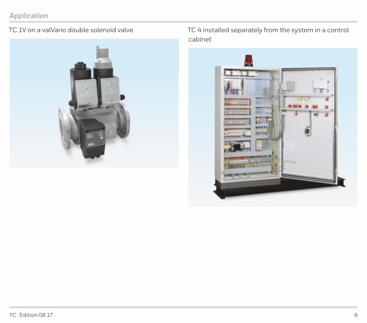
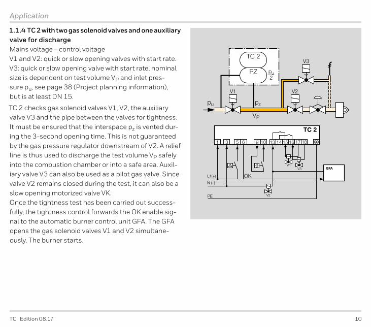
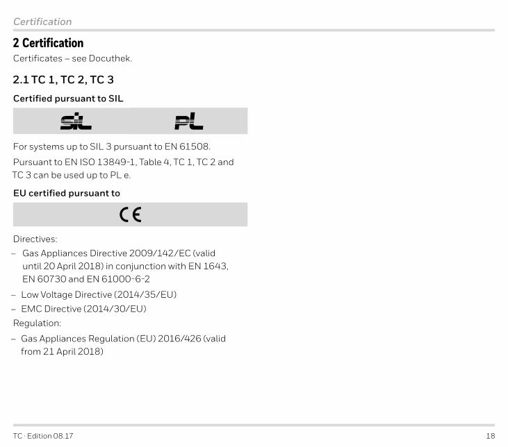

TC middot Edition 0817 37
Selection
4 Selection4 1 TC 1 TC 2 TC 3
4 1 1 Selection tableR N 05 WW QQ KK WK QK
TC 1V TC 1C TC 2 TC 3
= standard = availableOrder exampleTC 1V05WK
4 1 2 Type code Code DescriptionTC Tightness control1V1C23
For attachment to valVarioFor attachment to CG
For quick opening individual valvesFor quick or slow opening valves
RN
With Rp internal threadWith NPT internal thread
05 pu max 500 mbar
WQK
Mains voltage230 V AC 5060 Hz120 V AC 5060 Hz
24 V DC
WQK
Control voltage230 V AC 5060 Hz120 V AC 5060 Hz
24 V DC
4 2 TC 4
4 2 1 Selection table-1 -10 T N K
TC 410
= standard = availableOrder exampleTC 410-10T
4 2 2 Type code Code DescriptionTC Tightness control4 In control cabinet1 Testing before or after burner run0 External pressure switch required
-1-10
Test period10thinspndashthinsp60 s
100thinspndashthinsp600 s
TNK
Mains voltage220240 V AC 5060 Hz110120 V AC 5060 Hz
24 V DC=
TC middot Edition 0817 38
1
20
30
40
50
60
80
4
5
6
8
100
200 500
400
300
200
100
8090
60
70
50
40
30
20
1010
10
10
85 6 7
20
20
20
30
30
30
40
40
40
50
50
50
80
80
80
100 200
200
200
300
300
300
500
500
500
1000
1000
1000
2000
2000
2000
3000
3000
4000 6000
100
100
300 500 1000 2000 4000 6000 10000 20000 40000 100000
10
3
2
1
p u [
WC
]
p u [m
bar]
VP [ft3]
VP [ l ]
VAS 110
TC 3
VAS 115 VAS 125VAS 225 VAS 232VAS 340 VAS 350VAS 240 VAS 250
VAS 365
VAS 120
Project planning information
5 Project planning informationOn slow opening valves without start rate or pneumatically oper-ated valves the test volume can be supplied or discharged via auxiliary valves if discharge into the furnace chamber is impossible for process reasons
5 1 Selecting the auxiliary valvesExample VP = 3245 l (844 gal) pu = 50 mbar (195 WC)
Selecting auxiliary valve V1 selected rArr VAS 110
The valve is sufficiently large to vent the pipe between the valves
= natural gas ρ = 08 kgm3 (005 lbsft3)
= propane ρ = 201 kgm3 (013 lbsft3)
= air ρ = 129 kgm3 (008 lbsft3)
TC middot Edition 0817 39
Project planning information
5 2 Start rateThe tightness control TC requires a minimum start rate in order to carry out tightness tests on slow opening valves
up to 5 l (13 gal) test volume VP = 5 of maximum flow rate Qmax up to 12 l (312 gal) test volume VP = 10 of maximum flow rate Qmax
5 3 InstallationInstallation of TC 1 TC 2 TC 3 in the vertical or hori-zontal position housing coverindicators must not point upwards or downwards The electrical connection should preferably be pointing downwards or towards the outlet
TC 4 installation position any
Avoid condensation in the system
Do not store or install the unit in the open air
The tightness control TC must not be in contact with masonry minimum distance 20 mm (078 inches)
5 3 1 TC 1V for solenoid valves for gas VAS VCxThe valve actuator cannot be rotated on gas solenoid valves with a proof of closure switch VCxS or VCxG
When using a valvepressure regulator combination VCGVCVVCH the pressure regulator must be acti-vated with air during the entire test period tP This en-sures that the space between the valves can be filled and vented
A TC and a bypasspilot gas valve cannot be fitted to-gether on the same attachment side of the VAS or VCx
5 3 2 TC 1C for combination controls CGAn adapter plate is supplied for mounting the TC 1C to a combination control CG The connections for pu and pz are marked on the adapter plate
pu
pz
TC middot Edition 0817 40
Project planning information
5 3 3 TC 2An adapter plate is supplied for mounting the TC 2 to a gas solenoid valve
TC 2R Rp frac14TC 2N frac14 NPT
Rp frac14 (frac14 NPT)
pu
pz
pz
We recommend using Ermeto screw couplings to at-tach the adapter plate to the gas solenoid valve
The connections for pu and pz are marked on the adapt-er plate
pu
pz
pz
pu
pz
5 3 4 TC 3Connect the TC to the inlet pressure connection pu the intermediate pressure connection pz and the outlet pressure connection pd of the inlet valve Use a 12 x 15 or 8 x 1 pipe for the pipe connections
pz pd
pzpu
TC 3R Rp frac14TC 3N frac14 NPT
5 3 5 TC 4On the TC 4 the external pressure switch is mounted on the interspace between the valves to be monitored The TC can be installed separately from the valves For installation in the control cabinet housing for example the lower section can be secured with screws or mounted on a DIN rail
Snap attachment for DIN rail of 35 mm (136 inch) in width
TC middot Edition 0817 41
Project planning information
5 4 Electrical connection of TC 1 TC 2For the electrical connection of the TC to valves with a plug a socket can be supplied as an accessory see page 42 (Accessories)
5 5 Determining the relief line sizeThe nominal diameter of the relief line should be large enough to discharge the test volume VP The cross-sec-tion of the relief line should be 5 times the sum of the cross-sections of all pipes whose volume is intended to be discharged via the relief line
TC middot Edition 0817 42
Accessories
6 Accessories6 1 Socket
Standard socket 3 pins + PE blackB Order No 74916715
6 2 Valve connection cable
Standard socket 3 pins + PE black 4-core electrical cable cable length 045 m Order No 74960689
6 3 External pressure switch for TC 4
DG DGC
Gas pressure switches DG DGC for monitoring the pressure between the valves to be checked
For inlet pressures of 05 to 500 mbar (02 to 195 WC)
The switching differential may not exceed plusmn10 of the set switching pressure
(see Technical Information bulletin Pressure switch for gas DG DGC at wwwdocuthekcom)
AdjustmentThe external pressure switch is set to half the inlet pres-sure pu2 (only NO contact required) in order to check both valves with equal sensitivity
Example pu = 100 mbar (39 WC) set switching pressure pu2 = 50 mbar (195 WC)
TC middot Edition 0817 43
Technical data
7 Technical data7 1 TC 1 TC 2 TC 3
Electrical dataMains voltage and control voltage 120 V AC -15+10 5060 Hz 230 V AC -15+10 5060 Hz 24 V DC plusmn20
Power consumption (all LEDs green) 55 W at 120 V AC and 230 V AC 2 W at 24 V DC TC 3 plus 8 VA for an auxiliary valve
Fine-wire fuse 5 A slow-acting H 250 V pursuant to IEC 60127-25 F1 protection of valve outputs (terminals 15 and 16) fault signal (terminal 12) and supply of the control in-puts (terminals 2 7 and 8) F2 protection of safety interlockcontroller enable sig-nal (terminal 6)
The input current at terminal 1 must not exceed 5 A
Max load current (terminal 6) for safety interlockcon-troller enable and valve outputs (terminals 15 and 16) at 230120 V AC mains voltage max 3 A resistive load at 24 V DC mains voltage max 5 A resistive load
External fault signal (terminal 12) fault output at 120 V AC230 V AC24 V DC mains and control voltage max 5 A
fault output at 120 V AC230 V AC mains voltage 24 V DC control voltage max 100 mA
TC switching cycles 250000 pursuant to EN 13611
Reset using a button on the device or by remote reset
EnvironmentGas type natural gas town gas LPG (gaseous) biogas (max 01 -by-vol H2S) and air
The gas must be clean and dry in all temperature condi-tions and must not contain condensate
Inlet pressure pu 10 to 500 mbar (39 to 195 WC)
Measurement time tM 5 to 30 s adjustable Set at the factory to 30 s
Medium and ambient temperatures -20 to +60degC (-4 to +140degF) No condensation permitted
Long-term use in the upper ambient temperature range accelerates the ageing of the elastomer materials and reduces the service life
Storage temperature -20 to +40degC (-4 to +104degF)
Max installation altitude 2000 m AMSL
TC middot Edition 0817 44
Technical data
Mechanical dataLength of connection cable at 230 V AC120 V AC any at 24 V DC (supply connected to PE) max 10 m permitted at 24 V DC (supply not connected to PE) any
Cable cross-section min 075 mm2 (AWG 19) max 25 mm2 (AWG 14)
5 cable glands M16 x 15
Valve opening time 3 s
Housing made of impact-resistant plastic Connectors aluminium
Enclosure IP 65
Weight TC 1V 215 g (047 lbs) TC 1C with adapter 260 g (057 lbs) TC 2 with adapter 260 g (057 lbs) TC 3 420 g (092 lbs)
7 2 TC 4
Electrical dataMains voltage 110120 V AC -15+10 5060 Hz 220240 V AC -15+10 5060 Hz 24 V DC plusmn20
Power consumption 10 VA for 110120 V AC and 220240 V AC 12 W for 24 V DC
Fusing fine-wire fuse 5 A slow-acting H pursuant to IEC 127 also protects the valve outputs and external operating signal
Switching current for valvesenable output max 5 A
External operating signal with mains voltage max 5 A resistive load (UL listed 5 A for 120 V) max 2 A at cos ϕ = 035 (pilot duty)
Fault output dry contact (not internally fused) max 1 A for 220240 V (high voltage 264 V) max 2 A for 120 V
Reset using a button on the device Remote reset by applying control voltage (terminal 5)
TC middot Edition 0817 45
Technical data
EnvironmentGas type and inlet pressure pu dependent on external pressure switch
The pressure switch is set to half the inlet pressure pu2 The switching differential may not exceed plusmn10 of the set switching pressure see page 42 (External pres-sure switch for TC 4)
Test period tP TC 410-1 10 to 60 s adjustable Set at the factory to 10 s TC 410-10 100 to 600 s adjustable Set at the factory to 100 s
Ambient temperature -15 to +60degC (5 to 140degF) no condensation permitted Storage temperature -15 to +40degC (5 to 104degF)
Mechanical dataEnclosure IP 40
5 knock-out holes for M16 plastic cable glands
Screw terminals 25 mm2 (AWG 14)
Housing made of impact-resistant plastic
Weight approx 400 g (088 lbs)
TC middot Edition 0817 46
Technical data
7 3 Indicators and operating controls
TC 1 TC 2 TC 3
1
2
Power
1
2
Power = power supply
1
2
Power
= operating signal 1
2
Power
= valve 1 1
2
Power
= valve 2 = reset button
The LEDs can display messages using three colours (green yellow red) and permanent 1
2
Power
or flashing light 12
Power
LED MessageOperating status
1
2
Power green Power supply OK
1
2
Power
yellow TC is ready for operation safety interlock input signal interrupted
1
2
Power
green TC is ready for operation active safety interlock input signal1
2
Power
green V1 is tight1
2
Power
yellow V1 is untested1
2
Power
yellow Tightness test is running on V11
2
Power
red V1 is leaking1
2
Power
green V2 is tight1
2
Power
yellow V2 is untested1
2
Power
yellow Tightness test is running on V21
2
Power
red V2 is leakingAll yellow Initialization
see page 53 (Safety interlocks)
TC 4
OKTEST
1 2
TEST = TEST phase (yellow) OK = operating signal (green)
1 = fault valve 1 (red) 2 = fault valve 2 (red)
= reset button
TC middot Edition 0817 47
Technical data
7 4 Dimensions
1
2
Power
135(55)
135(53)
84(33)
1
2
Power
pd
pupz
pz
135(55)
217(85)
84(33)
92(36)
40(16)
95(37)
468(18)
Rp frac14(frac14 NPT)
Rp frac14(frac14 NPT)
OKTEST
12
113(44)
70(28)
oslash 5(02)
85(33)
35(14)
75(3)
TC 1 TC 2 TC 3 TC 4
Inlet pressure connection = pu intermediate pressure connection = pz and the outlet pressure connection = pd
7 5 Converting unitssee wwwadlatusorg
TC middot Edition 0817 48
Technical data
7 6 Safety-specific characteristic valuesFor systems up to SIL 3 pursuant to EN 61508
Mains and control voltage 120 V AC230 V ACDiagnostic coverage DC 914Mean probability of dangerous failure PFHD 173 x 10-9 1h
Mains voltage 120 V AC230 V AC control voltage 24 V DCDiagnostic coverage DC 913Mean probability of dangerous failure PFHD 172 x 10-9 1h
Mains and control voltage 24 V DCDiagnostic coverage DC 915Mean probability of dangerous failure PFHD 175 x 10-9 1h
GeneralMean probability of dangerous failure PFHD
Auxiliary valves with valve block on TC 3 02 x 10-9 1h
Type of subsystem Type B to EN 61508-2
Operating modeHigh demand mode pursuant to
EN 61508-4 Continuous operation (to EN 1643)
Mean time to dangerous failure MTTFd
1PFHD
Safe failure fraction SFF 975
Pursuant to EN ISO 13849-1 Table 4 TC 1 TC 2 and TC 3 can be used up to PL e
Relationship between the Performance Level (PL) and the Safety Integrity Level (SIL)
PL SILa ndashb 1c 1d 2e 3
Max service life under operating conditions 10 years after date of production
For a glossary of terms see page 53 (Glossary)
For further information on SILPL see wwwk-silde
TC middot Edition 0817 49
Safety information in accordance with EN 61508-2 for TC 1 TC 2 TC 3
8 Safety information in accordance with EN 61508-2 for TC 1 TC 2 TC 38 1 General
Scope of applicationMachinery Directive (200642EC) with the applicable harmonized standards
As set out in ldquoIndustrial thermoprocessing equipment ndash Part 2 Safety requirements for combustion and fuel handling systemsrdquo (EN 746-2)
AimThe TC 1 TC 2 TC 3 is a control unit pursuant to EN 60730-2-5 Section 63103
8 1 1 Type of actionThe automatic action of the TC 1 TC 2 TC 3 corre-sponds to Type 2 pursuant to EN 60730-1 Section 15
Operating modeThe TC 1 TC 2 TC 3 is capable of continuous operation and thus fulfils the characteristic of automatic action type 2AD pursuant to EN 60730-2-5 Section 64104
Switching off the safety-relevant output signals the safety-relevant output signals are switched off via relays This is a shut-down with micro switch pursuant to EN 60730-1 Sections 6432 and 692
Fault lock-outNon-volatile fault lock-out action type 2V pursuant to EN 60730-2-5 Section 64101
8 1 2 Other classifications
LoadThe outputs of the TC are primarily designed for resis-tive loads with a power factor ge 095
Automatic cyclesThe tightness control is designed for more than 250000 automatic cycles
Fault detection timeOn demand
Software classC (operates in a similar double-channel architecture with comparison)
8 1 3 Electrical dataSafety class
Safety class
Overvoltage categoryOvervoltage category III (hard wiringindustrial applica-tion)
Pollution degreeTC 1 TC 2 TC 3 pollution degree 2 (ge IP 65)
TC middot Edition 0817 50
Safety information in accordance with EN 61508-2 for TC 1 TC 2 TC 3
8 2 Interfaces
8 2 1 Electrical wiringAttachment type X to EN 60730-1
230 V AC 120 V ACConnection The TC 1 TC 2 TC 3 must be correctly phased in ac-cordance with the connection diagrams
24 V DCExtra-low voltage (ELV) If the TC 1 TC 2 TC 3 is supplied with ELV at which Mi-nus-GND are connected to PE all connected cables must not be longer than 10 m
If the TC 1 TC 2 TC 3 is supplied with ELV at which Minus-GND are not connected to PE all connected cables may be longer than 10 m
Safety extra-low voltage (SELV) If the TC 1 TC 2 TC 3 is supplied with SELV all con-nected components must also fulfil the requirements of SELV
Protected extra low voltage (PELV) If the TC 1 TC 2 TC 3 is supplied with PELV all con-nected cables must not be longer than 10 m
8 2 2 Connection terminals
Supply and control signal terminalsMains voltage = control voltage 24 V DC 120 V AC or 230 V AC power is supplied to the TC via connection terminals 1 (L1 (+)) and 3 (N (-)) Further terminal assignment see connection diagrams
120 V AC or 230 V AC mains voltage 24 V DC control voltage control voltage is supplied via connection terminals 8 (+) and 9 (-)
Terminals for automatic burner control unit and valvesSee connection diagrams
PE wire connection5 PE terminals for forwarding Connection to the sys-tem PE must be carried outwired by the user
8 2 3 Inputs
Safety interlocks (limits)
OK
V1
V2
Input voltage = mains voltage
Thermostatstart-up signal ϑInput voltage = control voltage
Resetremote reset
OK
V1
V2
Input voltage = control voltage
TC middot Edition 0817 51
Safety information in accordance with EN 61508-2 for TC 1 TC 2 TC 3
8 2 4 Outputs
Safety interlock
OK
V1
V2
OK enable signalat 230120 V AC mains voltage max 3 A resistive load at 24 V DC mains voltage max 5 A resistive load
Valve outputs V1 and V2at 230120 V AC mains voltage max 3 A resistive load at 24 V DC mains voltage max 5 A resistive load
Fault signal
OK
V1
V2
at 24 V DC 120 V AC or 230 V AC mains voltage and control voltage max 5 A resistive load
at 120 V AC230 V AC mains voltage and 24 V DC con-trol voltage max 100 mA
8 3 SIL and PL for TC 1 TC 2 TC 3
Safety functionThe basic safety function of the TC 1 TC 2 TC 3 is to check that automatic shut-off valves have closed effec-tively by detecting leakage
ClassificationClass C regulating and control functions
Demand modeHigh demand mode pursuant to IEC 61508-4
Hardware Fault Tolerance HFTHFT N = 0
SIL Safety Integrity LevelPL Performance LevelSee page 48 (Safety-specific characteristic values)
TC middot Edition 0817 52
Maintenance cycles
9 Maintenance cyclesTightness controls TC require little servicing We rec-ommend carrying out a function check once a year or twice a year in the case of biogas
TC middot Edition 0817 53
Glossary
10 Glossary10 1 Tightness controlThe term ldquotightness controlrdquo is the product name of product group TC from Elster GmbH Tightness control TC is a valve proving system (VPS)
10 2 Valve proving system VPSSystem to check that automatic shut-off valves have closed effectively by detecting leakage This system is frequently comprised of a program unit a measuring device valves and other functional equipment Valve proving systems for gas burners and gas appliances pursuant to DIN EN 1643 determine whether an auto-matic shut-off valve has closed on the basis of the de-tected leakage ratesee EN 1643
10 3 Safety interlocksLinking of all the relevant safety control and switching equipment for the use of the application The burner start enable signal is issued via the safety interlock out-put (terminal 6)
10 4 Diagnostic coverage DCMeasure of the effectiveness of diagnostics which may be determined as the ratio between the failure rate of detected dangerous failures and the failure rate of total dangerous failures
NOTE Diagnostic coverage can exist for the whole or parts of a safety-related system For example diagnos-tic coverage could exist for sensors andor logic system andor final elements Unit see EN ISO 13849-1
10 5 Operating modeHigh demand mode or continuous mode
Operating mode where the frequency of demands for operation made on a safety-related system is greater than one per year or greater than twice the proof-test frequencysee EN 61508-4
10 6 Hardware fault tolerance HFTA hardware fault tolerance of N means that N + 1 is the minimum number of faults that could cause a loss of the safety functionsee IEC 61508-2
TC middot Edition 0817 54
Glossary
10 7 Probability of dangerous failure PFHD Value describing the likelihood of dangerous failure per hour of a component for high demand mode or con-tinuous mode Unit 1hsee EN 13611A2
10 8 Mean time to dangerous failure MTTFd Expectation of the mean time to dangerous failuresee EN ISO 13849-1
TC middot Edition 0817
FeedbackFinally we are offering you the opportunity to assess this ldquoTechnical Information (TI)rdquo and to give us your opinion so that we can improve our documents further and suit them to your needs
ClarityFound information quicklySearched for a long timeDidnrsquot find informationWhat is missing
ComprehensionCoherentToo complicatedNo answer
ScopeToo littleSufficientToo wideNo answer
No answer
NavigationI can find my way aroundI got ldquolostrdquoNo answer
UseTo get to know the productTo choose a productPlanningTo look for information
My scope of functionsTechnical departmentSalesNo answer
Remarks
Elster GmbH Postfach 2809 middot 49018 Osnabruumlck Strotheweg 1 middot 49504 Lotte (Buumlren) GermanyTel +49 541 1214-0 Fax +49 541 1214-370 htslottehoneywellcomwwwkromschroedercom
ContactThe current addresses of our international agents are available on the Internet wwwkromschroederdeWeltweit200htmlampL=1
We reserve the right to make technical modifications in the interests of progressCopyright copy 2017 Elster GmbH All rights reserved
03
25
06
36
Contact
Feedback
- Tightness controls TC
- Contents
- 1 Application
-
- 11 Application examples
-
- 111 TC 1V with valVario controls
- 112 TC 1C with combination control CGD or CGV
- 113 TC 2 with two gas solenoid valves
- 114 TC 2 with two gas solenoid valves and one auxiliary valve for discharge
- 115 TC 2 with two gas solenoid valves and one auxiliary valve for discharge
- 116 TC 2 in a multiple burner system with several valves installed in series
- 117 TC 3 in a multiple burner system with several valves installed in series
- 118 TC 4 with two gas solenoid valves
- 119 TC 4 with two gas solenoid valves and one auxiliary valve for discharge
- 1110 TC 4 in a multiple burner system with two auxiliary valves for supply and discharge
- 1111 TC 4 in a multiple burner system with several valves installed in series
-
- 2 Certification
-
- 21 TC 1 TC 2 TC 3
- 22 TC 4
-
- 3 Function
-
- 31 TC 1 TC 2 TC 3
-
- 311 Connection diagrams for TC 1 TC 2
- 312 Connection diagrams for TC 3
- 313 Test procedure for TC 1 TC 2 TC 3
- 314 Test instant TC 1 TC 2 TC 3
- 315 Test instant for Mode 1 testing before burner run
- 316 Test instant for Mode 2 testing after burner run
- 317 Test instant for Mode 3 testing before and after burner run
- 318 Measurement time tM for TC 1 TC 2 TC 3
- 319 Calculation example for tM
-
- 32 TC 4
-
- 321 Connection diagram
- 322 Test procedure TC 4
- 323 TC 4 test instant
- 324 Test instant for Mode 1 testing before burner run
- 325 Test instant for Mode 2 testing after burner run
- 326 Test period tP for TC 4
- 327 Calculation example for tP
-
- 33 Test volume VP for TC 1 TC 2 TC 3 TC 4
- 34 Leakage rate QL
- 35 Animation
-
- 4 Selection
-
- 41 TC 1 TC 2 TC 3
-
- 411 Selection table
- 412 Type code
-
- 42 TC 4
-
- 421 Selection table
- 422 Type code
-
- 5 Project planning information
-
- 51 Selecting the auxiliary valves
- 52 Start rate
- 53 Installation
-
- 531 TC 1V for solenoid valves for gas VAS VCx
- 532 TC 1C for combination controls CG
- 533 TC 2
- 534 TC 3
- 535 TC 4
-
- 54 Electrical connection of TC 1 TC 2
- 55 Determining the relief line size
-
- 6 Accessories
-
- 61 Socket
- 62 Valve connection cable
- 63 External pressure switch for TC 4
-
- 7 Technical data
-
- 71 TC 1 TC 2 TC 3
- 72 TC 4
- 73 Indicators and operating controls
- 74 Dimensions
- 75 Converting units
- 76 Safety-specific characteristic values
-
- 8 Safety information in accordance with EN 61508-2 for TC 1 TC 2 TC 3
-
- 81 General
-
- 811 Type of action
- 812 Other classifications
- 813 Electrical data
-
- 82 Interfaces
-
- 821 Electrical wiring
- 822 Connection terminals
- 823 Inputs
- 824 Outputs
-
- 83 SIL and PL for TC 1 TC 2 TC 3
-
- 9 Maintenance cycles
- 10 Glossary
-
- 101 Tightness control
- 102 Valve proving system VPS
- 103 Safety interlocks
- 104 Diagnostic coverage DC
- 105 Operating mode
- 106 Hardware fault tolerance HFT
- 107 Probability of dangerous failure PFHD
- 108 Mean time to dangerous failure MTTFd
-
- Feedback
- Contact
-
- naechste_Seite 17
- naechste_Seite 29
- naechste_Seite 34
- naechste_Seite 33
- ftUebersicht Off
- ftVerstaendlichkeit Off
- ftFehlende_Info
- ftUmfang Off
- ftVerwendung_1 Off
- ftVerwendung_2 Off
- ftVerwendung_3 Off
- ftVerwendung_4 Off
- ftNavigation Off
- ftTaetigkeitsbereich Off
- ftBemerkung
- Michael Rehkamp Honeywell Kromschroumlder>btnSenden
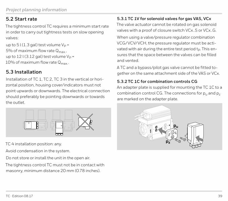
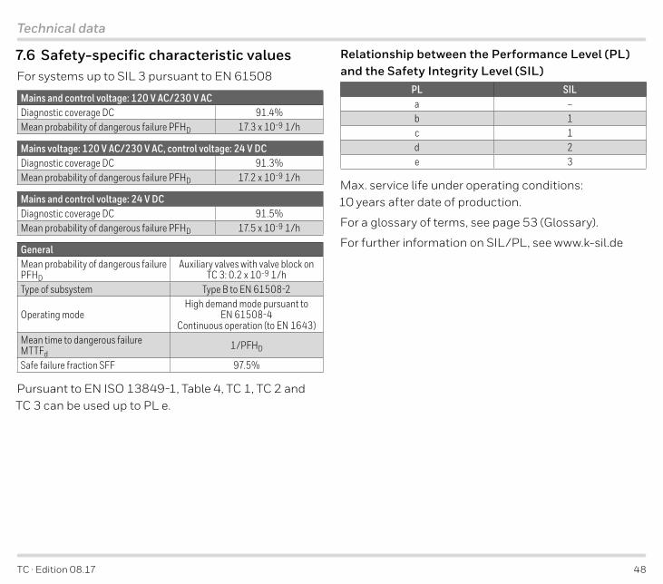
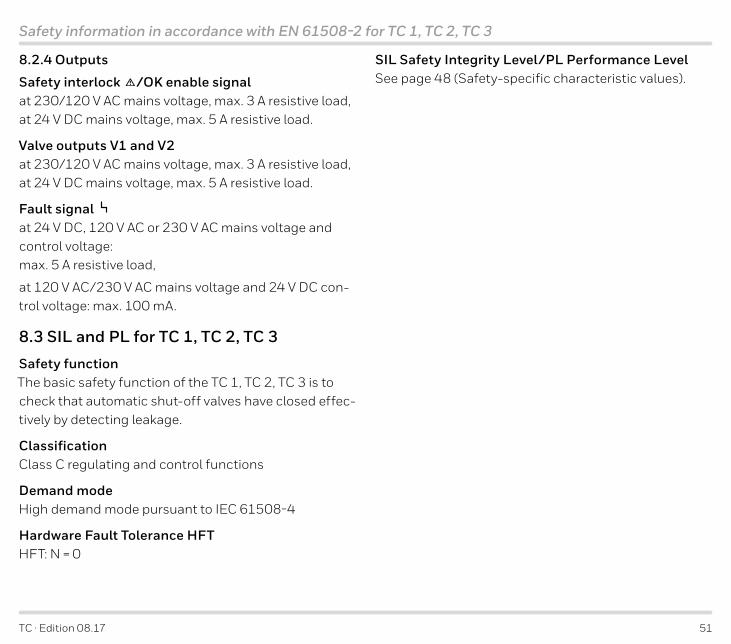


