January 2006
TB MED 524
TECHNICAL BULLETIN
OCCUPATIONAL AND ENVIRONMENTAL HEALTH
CONTROL OF HAZARDS TO HEALTH FROM LASER RADIATION
APPROVED FOR PUBLIC RELEASE; DISTRIBUTION IS UNLIMITED. HEADQUARTERS, DEPARTMENT OF THE ARMY

Report Documentation Page Form ApprovedOMB No. 0704-0188
Public reporting burden for the collection of information is estimated to average 1 hour per response, including the time for reviewing instructions, searching existing data sources, gathering andmaintaining the data needed, and completing and reviewing the collection of information. Send comments regarding this burden estimate or any other aspect of this collection of information,including suggestions for reducing this burden, to Washington Headquarters Services, Directorate for Information Operations and Reports, 1215 Jefferson Davis Highway, Suite 1204, ArlingtonVA 22202-4302. Respondents should be aware that notwithstanding any other provision of law, no person shall be subject to a penalty for failing to comply with a collection of information if itdoes not display a currently valid OMB control number.
1. REPORT DATE 31 JAN 2006
2. REPORT TYPE N/A
3. DATES COVERED -
4. TITLE AND SUBTITLE Control of Hazards to Health From Laser Radiation
5a. CONTRACT NUMBER
5b. GRANT NUMBER
5c. PROGRAM ELEMENT NUMBER
6. AUTHOR(S) 5d. PROJECT NUMBER
5e. TASK NUMBER
5f. WORK UNIT NUMBER
7. PERFORMING ORGANIZATION NAME(S) AND ADDRESS(ES) U.S. Army Washington, DC
8. PERFORMING ORGANIZATIONREPORT NUMBER
9. SPONSORING/MONITORING AGENCY NAME(S) AND ADDRESS(ES) 10. SPONSOR/MONITOR’S ACRONYM(S)
11. SPONSOR/MONITOR’S REPORT NUMBER(S)
12. DISTRIBUTION/AVAILABILITY STATEMENT Approved for public release, distribution unlimited
13. SUPPLEMENTARY NOTES The original document contains color images.
14. ABSTRACT
15. SUBJECT TERMS
16. SECURITY CLASSIFICATION OF: 17. LIMITATION OF ABSTRACT
SAR
18. NUMBEROF PAGES
293
19a. NAME OFRESPONSIBLE PERSON
a. REPORT unclassified
b. ABSTRACT unclassified
c. THIS PAGE unclassified
Standard Form 298 (Rev. 8-98) Prescribed by ANSI Std Z39-18


TB MED 524*
i
TECHNICAL BULLETIN HEADQUARTERS MEDICAL 524 DEPARTMENT OF THE ARMY Washington, DC, 31 January 2006
CONTROL OF HAZARDS TO HEALTH FROM LASER RADIATION
You can help to improve this bulletin. If you find any mistakes or have a recommendation to improve procedures, please let us know. Mail a memorandum or DA Form 2028 (Recommended Changes to Public and Blank Forms) directly to USACHPPM, ATTN: MCHB-TS-OLO, 5158 Blackhawk Road, Aberdeen Proving Ground, MD 21010-5403.
APPROVED FOR PUBLIC RELEASE; DISTRIBUTION IS UNLIMITED Paragraph Page CHAPTER 1 BACKGROUND Purpose 1–1 1 References 1–2 1 Explanation of abbreviations and terms 1–3 2 Responsibilities 1–4 2 CHAPTER 2 INTRODUCTION TO LASERS Background 2–1 5 Nature of light 2–2 5 Production of light 2–3 6 Components of a laser 2–4 7 Lasing medium 2–5 8 Pumping system 2–6 8 Optical cavity 2–7 9 Types of lasers 2–8 10 Temporal modes of operation 2–9 14 Spatial transverse electromagnetic modes of operation 2–10 15 Beam diameter 2–11 16 __________ * This bulletin supersedes TB MED 524, 20 June 1985
TB MED 524
ii
Paragraph Page Divergence 2–12 17 Hot spots 2–13 18 CHAPTER 3 EFFECTS OF LASER EXPOSURE Introduction 3–1 19 Skin 3–2 20 Eye 3–3 20 Medical surveillance 3–4 22 Overexposure reporting 3–5 22 Low-level adverse visual effects 3–6 22 CHAPTER 4 LASER HAZARD CLASSIFICATION AND EVALUATION Introduction 4–1 25 Laser classification 4–2 26 Hazard evaluations 4–3 29 Evaluation of personal injury hazards 4–4 30 Determining ocular maximum permissible exposures 4–5 30 Determining skin maximum permissible exposures 4–6 32 Use of apertures 4–7 33 Nominal ocular hazard distance 4–8 33 Nominal hazard zone 4–9 33 Specular reflection nominal ocular hazard distance 4–10 34 Buffer zones 4–11 34 CHAPTER 5 INDOOR CONTROL MEASURES Introduction 5–1 35 Types of control measures 5–2 36 Indoor laser installations 5–3 37 Warning signs 5–4 38 Education and training 5–5 43 Authorized personnel 5–6 43 Beam alignment procedures 5–7 43 CHAPTER 6 RANGE CONTROL AND OUTDOOR APPLICATIONS Force-on-Force exercises 6–1 45 Background 6–2 45 Laser systems 6–3 47 User instructions 6–4 49 Range boundaries 6–5 49 Range control procedures 6–6 54 Image intensifiers 6–7 55
TB MED 524
iii
Paragraph Page Countdown 6–8 55 Communications 6–9 55 Operation outside of range area 6–10 55 Laser operations from aircraft 6–11 56 Hangar, garage, and maintenance shop procedures 6–12 58 Inclement weather 6–13 58 Visual interference hazards 6–14 58 CHAPTER 7 LASER EYE PROTECTIVE DEVICES Background 7–1 63 Operational requirements for laser protective eyewear 7–2 64 Other laser protective devices 7–3 65 Laser eye protective device parameters 7-4 66 Selecting appropriate eyewear 7–5 69 Army laser eye protectors 7–6 70 Commercial sources of laser eye protectors 7–7 73 Inspection and testing of laser eye protective devices 7–8 73 CHAPTER 8 NONBEAM HAZARDS
Introduction 8–1 75 Electrical hazards 8–2 75 Prevention of electrical shock 8–3 75 First-aid procedures for electrical shock victims 8–4 77 Laser-generated air contaminants 8–5 77 Collateral and plasma radiation 8–6 77 Fire hazards 8–7 78 Explosion hazards 8–8 78 Compressed gases 8–9 78 Laser dyes 8–10 79 Cryogenics 8–11 79 Noise 8–12 79 Confining space 8–13 79 Ergonomics 8–14 80
CHAPTER 9 SAFETY DESIGN REQUIREMENTS FOR MILITARY LASERS Overview 9–1 81 Applicability 9–2 81 Basic policy 9–3 82 Tailoring 9–4 82 Design requirements for exempted lasers 9–5 82

TB MED 524
iv
Paragraph Page Design requirements for Class 3B and Class 4 exempted lasers 9–6 90 Laser test sets 9–7 92 CHAPTER 10 DESIGN REQUIREMENTS FOR ASSOCIATED SUPPORT EQUIPMENT Introduction 10–1 93 General requirements 10–2 93 Requirements for Class 1, Class 2, and Class 3a laser support equipment 10–3 93 Requirements for Class 3b and Class 4 laser support equipment 10–4 93 CHAPTER 11 LASER SAFETY IN HEALTHCARE FACILITIES Introduction 11–1 95 Healthcare laser system–laser hazard classification 11–2 95 Effects of medical lasers on the biological system 11–3 96 Healthcare laser system–non–Surgical lasers 11–4 98 Medical lasers–control and operation of healthcare laser systems 11–5 98 Healthcare laser system–multi-wavelength laser protective 11–6 99 eyewear hazards CHAPTER 12 LASER SAFETY PROGRAM–RPO/LSO RESPONSIBILITIES Introduction 12–1 101 General requirements 12–2 101 Operational procedures 12–3 103 Appendix A REFERENCES 105 Appendix B CALCULATIONS FOR HAZARD EVALUATION AND CLASSIFICATION Introduction B–1 111 Definitions B–2 111 Viewing the primary beam (direct intrabeam viewing) B–3 114 Viewing the reflected beam B–4 114 Other factors B–5 117 Calculations for hazard evaluation and classification B–6 118 Maximum permissible exposure determination B–7 121 Laser classification B–8 135
TB MED 524
v
Paragraph Page Central beam irradiance or radiant exposure for circular beams B–9 138 Beam diameter and beam divergence for circular beams B–10 140 Beam irradiance or radiant exposure for rectangular and elliptical beams B–11 143 Beam diameter versus range B–12 144 Atmospheric attenuation B–13 145 Laser range equation B–14 145 Nominal ocular hazard distance B–15 149 Viewing aided by an optical system B–16 150 Hazards from specular reflections B–17 153 Hazards from diffuse reflections B–18 154 Scanning lasers B–19 158 Laser protective eyewear B–20 160 Appendix C MEDICAL SURVEILLANCE Introduction C–1 165 Employment status and vision screening C–2 165 Classification of laser workers C–3 166 Laser medical surveillance/assessment C–4 166 Protective measures required C–5 166 Emergency care for laser injury C–6 167 Reporting C–7 167 Appendix D SAMPLE SAFETY GUIDELINES Introduction D–1 171 Scope D–2 171 Safety guidelines for ocular safety in healthcare facilities D–3 173 Safety guidelines for multiple integrated laser engagement system and related optical equipment for maintenance workers D–4 175 Safety guidelines for training with portable fire control lasers D–5 177 Safety guidelines for training with tactical laser pointers D–6 179 Safety guidelines for maintenance shop operation of fire control lasers D–7 181 Safety guidelines for laser operations D–8 183 Safety guidelines for laser ranges D–9 187 Safety guidelines for Force-on-Force training with tactical and training lasers D–10 189 Safety guidelines for controlled access to the laser room D–11 193

TB MED 524
vi
Paragraph Page Safety guidelines for laser operation and safety procedures during preoperative and operating room services D–12 195 Safety guidelines for handling of medical laser fiber delivery systems D–13 199 Safety guidelines for nonbeam hazards associated with medical lasers D–14 201 Safety guidelines for carbon dioxide surgical laser operation D–15 203 Safety guidelines for photocoagulators D–16 205 Appendix E MAXIMUM PERMISSIBLE EXPOSURES Introduction E–1 207 Scope E-2 207 Appendix F CONTROL MEASURES Introduction F–1 227 Scope F–2 227 Appendix G EYE PROTECTION Control measures G–1 231 Optical density requirements for laser systems G–2 231 Appendix H SPECIFIC LASER SYSTEMS Introduction H–1 233 Fielded laser systems H–2 233 Appendix I STANDARDIZATION WITH INTERNATIONAL STANDARDS–INTERNATIONAL ELECTROTECHNICAL COMMISSION 608.25–1.1–1998 Classification guidelines I–1 245 Federal Laser Product Performance Standard and the American National Standards Institute I–2 245 International Electrotechnical Commission I–3 246 Glossary 249
TB MED 524
vii
List of Tables Number Title Page 2–1 Common laser wavelengths 11 4–1 Laser classification and risk assessment 27 5–1 Control measures 37 9–1 Minimum optical density values for magnifying optical sights 84 9–2 Minimum optical density values for non-magnifying optical sights 85 11–1 Typical healthcare laser systems 97 12–1 Operational elements 102 B–1 Definitions of mathematical symbols 111 B–2 Atmospherically corrected values of nominal ocular hazard distance (NOHD) in kilometers, assuming µ = 0.05 km-1, when the NOHD, with or without optics in vacuum (NOHD(v)), is known 152 B–3 Diffuse reflection hazard from pulsed lasers in retinal hazard region (400 nanometers to 1400 nanometers) 157 B–4 Diffuse reflection hazards form visible (400 nanometers to 700 nanometers) continuous wave lasers 158 C–1 Symptoms, signs, diagnosis, and treatment of laser-induced injuries 168 D–1 Precautions/Danger areas for laser systems 185 E–1 Maximum permissible exposure for small source ocular exposure to a laser beam 208 E–2 Maximum permissible exposure for extended source ocular exposure to a laser beam for long-exposure durations 210 E–3 Parameters and correction factors 212 E–4 Maximum permissible exposure for skin exposure to a laser beam 213 E–5 Limiting apertures (irradiance and radiant exposure) and limiting cone angles γ (radiance and integrated radiance) for hazard evaluation and accessible emission limit determination 214 E–6 Measurement apertures for classification 215 F–1 Administrative and procedural control measures for all laser classes 228 F–2 Engineering control measures for all laser classes 229 G–1 Simplified method for selecting laser eye protection for small source viewing (wavelengths between 400 nanometers and 1400 nanometers) 231 H–1 Nominal ocular hazard distance (atmospheric attenuated), range safety information, and eye protection requirements for vehicle-mounted laser systems 238 H–2 Nominal ocular hazard distance (atmospheric attenuated), range safety information, and eye protection requirements for man-transportable laser systems 239

TB MED 524
viii
Number Title Page H–3 Nominal ocular hazard distance (atmospheric attenuated), range safety information, and eye protection requirements for aircraft-mounted laser systems 241 H–4 Nominal ocular hazard distance (atmospheric attenuated), range safety information, and eye protection requirements for ship-mounted laser systems 242 H–5 Nominal ocular hazard distance (atmospheric attenuated), range safety information, and eye protection requirements for commercial-off-the- shelf man-transportable laser systems 243 H–6 Nominal ocular hazard distance (atmospheric attenuated), range safety information, and eye protection requirements for commercial-off-the- shelf aircraft-mounted laser systems 243 H–7 Cautionary distances for eye exposure to weapons simulators and laser training devices 244 I–1 Comparison of classification schemes 246
List of Figures Number Title Page 2–1 The electromagnetic spectrum 6 2–2 Emission of radiation by transmission of an electron from a higher energy state to a lower energy state 7 2–3 Three-level energy diagram 8 2–4 Population inversion 9 2–5 Three typical optical cavities 10 2–6 Schematic of solid-state laser with optical pumping 12 2–7 Schematic of a liquid-dye laser with optical pumping 12 2–8 Schematic of helium-neon laser with electron collision pumping (representative of small gas lasers) 13 2–9 Schematic of carbon dioxide gas transport laser 13 2–10 Schematic of gallium arsenide laser with direct-current (electron collision) pumping (representative of semiconductor or injection lasers) 14 2–11 Pulse characteristics of several different lasers 15 2–12 Common transverse electromagnetic modes 16 2–13 Irradiance or radiant exposure at various points in the beam cross section 17 2–14 Definition of divergence angle 17 3–1 Adverse effects on eye and skin from nonionizing radiation 19 3–2 Anatomy of the eye 20 3–3 Absorption of electromagnetic radiation by the eye 21

TB MED 524
ix
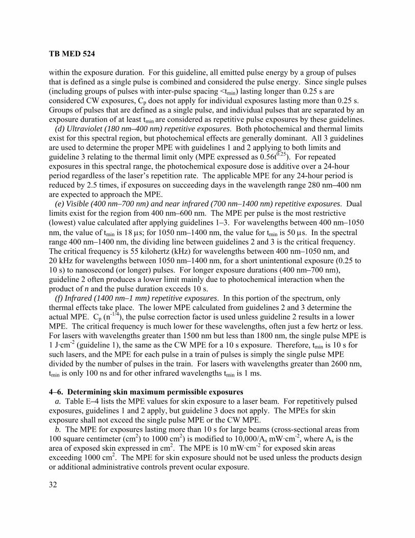
Number Title Page 5–1 Sample warning sign for Class 3b laser 39 5–2 Sample warning sign for Class 4 laser 39 5–3 Sample warning sign for Class 4 double neodymium:yttrium aluminum garnet laser 40 5–4 Sample warning sign for Class 4 neodymium:yttrium aluminum garnet laser 40 5–5 Sample warning sign for Class r carbon dioxide laser 41 5–6 Sample International Electrotechnical Commission warning sign 42 5–7 Sample warning sign for temporary laser controlled area 43 6–1 Laser range terrain profiles with backstop 46 6–2 Diffuse and specular reflections 47 6–3 Specular reflection from water or horizontal flat glass on laser range 47 6–4 Reflected intrabeam viewing 48 6–5 Sample laser range warning sign 50 6–6 Sample range backstop 51 6–7 Buffer zones 52 6–8 Laser safety danger zones 53 6–9 Buffer zone for a laser designator with a ground-based target 57 6–10 Laser maintenance test range 58 6–11 Visual interference flight zones 60 6–12 Critical and laser free zones 61 6–13 Laser free zone 62 7–1 Commercially available laser eye protectors 64 7–2 Relative spectral luminous efficiency (normalized) curves for photopic (daylight) and scotopic (night) vision 68 7–3 Examples of damage to laser protective devices 69 7–4 Ballistic and laser protective spectacles 71 7–5 Special protective eyewear, cylindrical system 72 7–6 Sun, wind, and dust goggles 72 7–7 M40/M42 gas mask laser/ballistic outsert 73 9–1 Exemption label 1 83 9–2 Exemption label 2 83 9–3 Example of a label for Class 1 lasers 86 9–4 Example of a warning label for Class 2 lasers 86 9–5 Example of a warning label for Class 3a visible (400 nanometers to 700 nanometers) lasers 87 9–6 Example of a warning label for Class 3a infrared (> 700 nanometers) and ultraviolet (< 400 nanometers) lasers 87 9–7 Example of a warning label for Class 3b lasers 88 9–8 Example of a warning label for Class 4 lasers 88

TB MED 524
x
Number Title Page 9–9 Example of typical International Electrotechnical Commission warning labels 89 9–10 Example of an interlock label 89 B–1 Specular reflectance from both surfaces of plate glass having an index of refraction of 1.5 115 B–2 Hazard envelopes created by a laser beam incident upon a vertically oriented flat (30 centimeter x 15 centimeter) glass surface 116 B–3 Intrabeam viewing–direct beam (primary beam) 119 B–4a Intrabeam viewing–specularly reflected from flat surface (secondary beam) 119 B–4b Intrabeam viewing–specularly reflected from curved surface (secondary beam) 120 B–5 Viewing a diffuse reflection–“r” represents the distance from the laser to the diffuse target, and r1 represents the distance from the target to the eye 120 B–6 Beam expansion with distance from the laser 145 B–7 Using the laser range equation to determine nominal ocular hazard distances 150 C–1 Laser injury evaluation matrix 169 E–1 Maximum permissible exposures for visible and near infrared (400 nanometers to 1400 nanometers) for pulsed small sources 216 E–2 Maximum permissible exposures for small and extended source ultraviolet radiation for exposure durations from 10-9 to 30,000 seconds for ocular exposures and 10-9 to 10-3 second for skin exposure 217 E–3 Maximum permissible exposures for ultraviolet (315 nanometers to 400 nanometers) and infrared (1400 nanometers to 1 millimeter) for single pulses or continuous exposure to small or extended sources 218 E–4 Maximum permissible exposures for ocular exposure to visible laser radiation (400 nanometers to 700 nanometers) for single pulses or continuous exposure (small or extended sources) 219 E–5 Small source ocular maximum permissible exposures (α ≤ 1.5 milliradian) for visible and near infrared (400 nanometers to 1400 nanometers) (Solid lines are maximum permissible exposures based on thermal effects, and dashed lines are maximum permissible exposures based on photochemical effects) 220 E–6 Extended source ocular maximum permissible exposures (α = 3 milliradian) for visible and near infrared (400 nanometers to 1400 nanometers) (Solid lines are maximum permissible exposures based on thermal effects, and dashed lines are maximum permissible exposures based on photochemical effects) 221
TB MED 524
xi
Number Title Page E–7 Extended source ocular maximum permissible exposures (α = 11 milliradian) for visible and near infrared (400 nanometers to 1400 nanometers) (Solid lines are maximum permissible exposures based on thermal effects, and dashed lines are maximum permissible exposures based on photochemical effects) 222 E–8 Extended source ocular maximum permissible exposures (α = 25 milliradian) for visible and near infrared (400 nanometers to 1400 nanometers) (Solid lines are maximum permissible exposures based on thermal effects, and dashed lines are maximum permissible exposures based on photochemical effects) 223 E–9 Extended source ocular maximum permissible exposures (α = 50 milliradian) for visible and near infrared (400 nanometers to 1400 nanometers) (Solid lines are maximum permissible exposures based on thermal effects, and dashed lines are maximum permissible exposures based on photochemical effects) 224 E–10 Extended source ocular radiance maximum permissible exposures (α ≥ 110 milliradian) for visible and near infrared (400 nanometers to 1400 nanometers) (Solid lines are maximum permissible exposures based on thermal effects, and dashed lines are maximum permissible exposures based on photochemical effects) 225 E–11 Extended source ocular radiance maximum permissible exposures (α ≥ 100 milliradian) for visible and near infrared (400 nanometers to 1400 nanometers) for pulsed or continuous wave exposures less than 1 second 226

TB MED 524
xii
This page intentionally left blank
TB MED 524
1
CHAPTER 1
BACKGROUND
1–1. Purpose a. This bulletin provides guidelines and establishes procedures for personnel protection from laser radiation within the framework of currently documented experimental evidence. Medical guidance is limited to biological data available. This bulletin encompasses the portion of the electromagnetic spectrum in which laser radiation can be produced including: ultraviolet (UV), visible light, and infrared (IR) radiation. b. This bulletin applies to those activities established and operated at active Army, Army National Guard/Army National Guard of the United States, U.S. Army Reserve, Department of the Army (DA) personnel, and Corps of Engineers facilities. c. Provisions of this publication are subject to the latest editions of three international standardization agreements (STANAG): STANAG 2900, STANAG 3606, and STANAG 3828 found in appendix A. d. It is Army policy to follow guidance in the American National Standards Institute (ANSI) Z136 series of standards. Additional guidance is contained in this document for U.S. Army laser systems used both indoors and outdoors for laser research, training, and tactical and strategic applications. Consult Military Handbook (MIL–HDBK)–828A for specific guidance on fielded military laser systems found in appendix A. e. The evaluation of laser hazards often requires highly technical calculations by experienced individuals. See appendix B for sample calculations of potential hazards. Detailed technical information for highly specialized laser applications may be found in MIL–HDBK–828A. Assistance in the control of laser hazards on a range is available from the Laser/Optical Radiation Program (LORP) at the U.S. Army Center for Health Promotion and Preventive Medicine (USACHPPM), ATTN: MCHB–TS–OLO, 5158 Blackhawk Road, Aberdeen Proving Ground, MD 21010-5403 or electronically at: http://chppm-www.apgea.army.mil/laser/laser.html. 1–2. References Required and related publications and prescribed and referenced forms are listed in appendix A.
Use of trademarked names does not imply endorsement by the U.S. Army but is intended only to assist in identification of a specific product.

TB MED 524
2
1–3. Explanation of abbreviations and terms Abbreviations and special terms used in this bulletin are explained in the glossary. 1–4. Responsibilities a. The Surgeon General will evaluate potential health hazards to personnel operating, testing, or associated with lasers. (See Army Regulation (AR) 10–5.) b. The installation Laser Safety Officer (LSO) and/or Radiation Safety Officer (RSO) will⎯ (1) Be trained in laser safety by taking a laser hazards course such as offered by the USACHPPM LORP. (2) Ensure that the medical surveillance guidance provided in appendix C is followed. c. The Commander, USACHPPM will⎯ (1) Provide a team to investigate an alleged exposure to laser radiation when directed to do so by The Surgeon General. (2) Establish the nominal ocular hazard distance (NOHD) of the standard fielded lasers. (3) Determine minimum necessary optical density (OD) requirements for standard fielded lasers. d. The USACHPPM LORP will⎯ (1) Provide specific guidance for all Force-on-Force training exercises for hazard assessment to ensure safety of personnel if Class 3b or Class 4 lasers are used. Contact the USACHPPM LORP at http://chppm-www.apgea.army.mil/laser/laser.html for guidance on Force-on-Force training operations. (2) Evaluate any health hazards associated with the development of Army materiel including commercial off-the-shelf (COTS) laser devices. (3) Perform any necessary health hazard analyses in order to minimize any potential hazardous exposures to laser/optical systems. Effective 28 November 1995, the USACHPPM was appointed lead agent for the Army Health Hazard Assessment Program. (See AR 40–10). e. The Director, U.S. Army Medical Research Detachment - Walter Reed Army Institute of Research (USAMRD–WRAIR), Ocular Hazards Research will conduct research and development to obtain data on biomedical effects of laser radiation. f. Installation commanders will perform responsibilities set forth in AR 11–9 and AR 385–63. g. The command safety manager will perform responsibilities set forth in AR 385-10 and AR 385–63. h. Firing/lasing unit commanders will perform responsibilities set forth in AR 11–9, AR 385–63, Department of the Army Pamphlet (DA Pam) 385–63, MIL–HDBK–828A, and Joint Publication (JP) 3–09.1. i. The laser range safety officer/laser range safety noncommissioned officer (LRSO/LRSNCO) will ensure that all personnel authorized to participate in the laser operation are thoroughly instructed regarding safety precautions to be followed. See appendix D for safety guidelines to― (1) Ensure that established target areas, with buffer zones around the target area as defined by the greatest laser-to-target distance, are observed.

TB MED 524
3
(2) Provide adequate surveillance of the target area to ensure that unauthorized personnel do not enter the target area. (3) Ensure that communication with personnel in the target area is maintained and that required protective eyewear is worn during the operation of the laser system. (4) Report immediately to the LSO/RSO any suspected eye injury due to laser radiation so that an examination and care can be provided as soon as possible (within 24 hours of the exposure). See appendix C for information concerning medical surveillance.

TB MED 524
4
This page intentionally left blank

TB MED 524
5
CHAPTER 2
INTRODUCTION TO LASERS
2–1. Background a. The term Laser is an acronym derived from Light Amplification by Stimulated Emission of Radiation. The effects of laser radiation are essentially the same as optical radiation that is generated by more conventional UV, IR, and visible optical sources. The biological implications attributed to laser radiation usually result from the very high beam collimation, beam intensities, and monochromaticity of many lasers. Lasers differ from conventional sources of optical radiation primarily in their ability to attain highly coherent radiation (that is, light waves in phase). The increased directional intensity of the optical radiation generated by a laser results in concentrated optical beam irradiances at considerable distances. b. Recent developments in laser technology have resulted in an increase in the use of these devices for military research and field use. Field military lasers are used primarily for target acquisition, training, and fire control. These lasers are termed rangefinders, target designators and direct-fire simulators. The widespread use of laser systems increases the probability of personnel exposure to injurious levels of laser radiation. Although lasers have useful characteristics, they are potentially hazardous, and adequate safeguards must be provided. Laser radiation should not be confused with ionizing radiation (that is, X-ray and gamma rays). c. Lasers also perform a variety of non-military functions and come in many shapes and forms. Dangerous lasers can be smaller than a pen or larger than a truck and can be every size and shape in between. Lasers are also being used in communications, precision distance measurements, guidance systems, metalwork, photography, holography, and medicine. d. The term laser is applied to devices that operate from stimulated emission with an output wavelength usually between approximately 100 nanometers (nm) and 1 millimeter (mm). Most lasers operate in one or more of the following output temporal modes (para 2–9): (1) Continuous wave (CW). (2) Pulsed, including: single-pulsed, Q-switched, mode-locked, and repetitively pulsed. 2–2. Nature of light a. The word light as properly used refers to that portion of the electromagnetic spectrum that produces a visual effect. It was first shown by James Clerk Maxwell in 1873 that light is electromagnetic radiation that propagates at approximately 3 × 10⁸ meters per second (m/s) in vacuum. Albert Einstein later postulated that the velocity of light in vacuum was constant and independent of the frame of reference throughout the universe and is the ultimate speed at which energy may be transmitted. The independence of the speed of light in vacuum has been verified experimentally numerous times. b. Quantum mechanics was developed to describe the experimentally observed phenomenon that energy interacts with matter in discrete steps. Energy can be considered to consist of quanta (packets) of energy, called photons. The amount of energy (Q), represented by one photon, is

TB MED 524
6
proportional to the electromagnetic wave frequency (ν), with the proportionality constant being Planck's constant (h)⎯
Q = hν
c. Scientists have made use of almost the entire electromagnetic spectrum from zero hertz (Hz) (such as direct current from storage batteries) to 1024 hertz (Hz) (the very hard X-rays used for nondestructive inspection of metal parts). Figure 2–1 shows the electromagnetic spectrum and some of its uses and properties.
Figure 2–1. The electromagnetic spectrum
2–3. Production of light a. Electromagnetic radiation, in the form of photons, is emitted whenever a charge is accelerated. This happens, for example, every time an electron drops from a higher energy state to a lower energy state in an atom, ion, or molecule (see figure 2–2). The energy of the photon is proportional to the change in energy of the atom, ion, or molecule.

TB MED 524
7
Figure 2–2. Emission of radiation by transmission of an electron from a higher energy state to a lower energy state
b. In ordinary light sources, electron transitions from higher energy states to lower energy states occur randomly and spontaneously, and one photon has no correlation with another. In a laser, however, these transitions are stimulated by other photons of exactly the same energy, wavelength, phase, and direction. c. Electrons must be raised to higher energy levels before they can make the transition to lower energy levels and emit photons. There are many ways in which electrons can be raised to higher energy levels or become "excited," such as⎯ (1) Heating, as in the filament of an incandescent lamp. (2) Collisions with other electrons, as in a fluorescent lamp discharge or in a television picture tube. (3) Absorbing energy from photons, as in luminescent paint on a watch dial. (4) Chemical reactions, as in a flame. d. In addition to the familiar electronic energy levels, laser action can also result from vibrational and rotational energy levels of molecules, as in the carbon dioxide laser. 2–4. Components of a laser a. A laser has three basic components⎯ (1) A lasing medium. (2) A “pumping” system (that is, supplying the energy to excite the molecules). (3) A resonant optical cavity.
TB MED 524
8
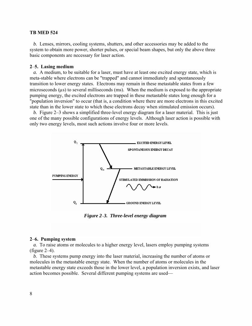
b. Lenses, mirrors, cooling systems, shutters, and other accessories may be added to the system to obtain more power, shorter pulses, or special beam shapes, but only the above three basic components are necessary for laser action. 2–5. Lasing medium a. A medium, to be suitable for a laser, must have at least one excited energy state, which is meta-stable where electrons can be "trapped" and cannot immediately and spontaneously transition to lower energy states. Electrons may remain in these metastable states from a few microseconds (μs) to several milliseconds (ms). When the medium is exposed to the appropriate pumping energy, the excited electrons are trapped in these metastable states long enough for a "population inversion" to occur (that is, a condition where there are more electrons in this excited state than in the lower state to which these electrons decay when stimulated emission occurs). b. Figure 2–3 shows a simplified three-level energy diagram for a laser material. This is just one of the many possible configurations of energy levels. Although laser action is possible with only two energy levels, most such actions involve four or more levels.
Figure 2–3. Three-level energy diagram
2–6. Pumping system a. To raise atoms or molecules to a higher energy level, lasers employ pumping systems (figure 2–4). b. These systems pump energy into the laser material, increasing the number of atoms or molecules in the metastable energy state. When the number of atoms or molecules in the metastable energy state exceeds those in the lower level, a population inversion exists, and laser action becomes possible. Several different pumping systems are used—

TB MED 524
9
Note: E: electron energy states
Figure 2–4. Population inversion c. These systems pump energy into the laser material, increasing the number of atoms or molecules in the metastable energy state. When the number of atoms or molecules in the metastable energy state exceeds those in the lower level, a population inversion exists, and laser action becomes possible. Several different pumping systems are used⎯ (1) Optical pumping uses an intense light source, such as an xenon flashtube or another laser (for example, an argon laser or diode). (2) Electron collision pumping is accomplished by passing an electric current through the laser material or by accelerating electrons from an electron gun to impact on the laser material (for example, helium neon laser). (3) Chemical pumping is based on energy released in the making and breaking of chemical bonds (for example, hydrogen fluoride lasers). 2–7. Optical cavity a. A resonant optical cavity is formed by placing a mirror at each end of the laser material so that the photons of light may be reflected from one mirror to the other, passing back and forth through the laser medium (figure 2–5 - simple flat mirror system (top); rotating prism Q-switch system (middle); confocal mirror system (bottom)). b. Lasers are constructed in this way so that the photons pass through the medium many times and are continuously amplified each time. One of the mirrors is only partially reflecting and permits a fraction of the beam energy to be transmitted out of the cavity.

TB MED 524
10
Figure 2–5. Three typical optical cavities 2–8. Types of lasers a. Lasers are often designated by the type of laser material in the optical cavity. Lasers can produce radiation in the UV, IR and visible regions of the spectrum. b. Table 2–1 lists several common laser wavelengths and the medium used to produce the laser.

TB MED 524
11
Table 2–1 Common laser wavelengths1
CIE band Wavelength nm
Medium Typical Operation
UV-C, B, A2
UV-A UV-A UV-A Visible light Visible light Visible light Visible light Visible light Visible light Visible light Visible light Visible light IR-A3
IR-A IR-A IR-A IR-A IR-B6
IR-B IR-C IR-C7
193, 222, 248, 308, 351 325 327 350 441.6 458 ,488 ,514.5 568, 647 532 511-578 632.8 670 694.3 560-640 700-800 850 905 1060 1064 1540 2900 3900 10,600
Excimer Helium-cadmium Nitrogen Argon Helium-Cadmium Argon Krypton Nd:YAG frequency-doubled Copper vapor Helium-neon Diode Ruby Rhodamine 6G dye Alexandrite GaA1As4
Gallium-arsenide Nd:glass Nd:YAG5
Erbium:YAG Hydrogen fluoride Deuterium fluoride Carbon dioxide
CW/Pulsed CW Repetitively pulsed CW CW CW CW Pulsed Repetitively pulsed CW CW Pulsed CW/Pulsed Repetitively pulsed Repetitively pulsed Repetitively pulsed Pulsed Pulsed Pulsed Pulsed Pulsed CW
Notes: 1 Source: Modified from Field Manual (FM) 8-50, table A-1 2 Ultraviolet radiation: (a) UV–C (100 nm–280 nm) (b) UV–B (280 nm–315 nm) (c) UV–A (315 nm–400 nm) 3 IR–A (700 nm–1400 nm) 4 GaA1As: Gallium Aluminum Arsenide 5 Nd:YAG: Neodymium:Yittrium Aluminum Garnet 6 IR–B (1400 nm–3 micrometer (µm)) 7 IR–C (3 µm–1000 µm) c. Solid-state lasers employ a glass or crystalline material (figure 2–6) and commonly employ optical pumping.

TB MED 524
12
Figure 2–6. Schematic of solid-state laser with optical pumping
d. Liquid lasers employ an active material in a liquid solution or suspension, usually a dye (figure 2–7). Liquid lasers commonly employ optical pumping, although some types of liquid lasers have employed chemical-reaction pumping.
Figure 2–7. Schematic of a liquid-dye laser with optical pumping
e. Gas lasers employ a pure gas or a mixture of gases (figures 2–8 and 2–9). Figure 2–9 represents the larger type of flowing gas laser. A still larger type of gas laser, known as a gas dynamic laser (not shown), employs a combustion chamber and supersonic nozzle for population

TB MED 524
13
inversion. Gas lasers usually employ electron collision pumping, although some types of gas lasers have employed chemical-reaction pumping.
Figure 2–8. Schematic of helium-neon laser with electron collision pumping
(representative of small gas lasers)
Note: DC: Direct Current
Figure 2–9. Schematic of carbon dioxide gas transport laser
f. Semiconductor lasers employ diode materials (figure 2–10). Semiconductor lasers may be optically pumped by another laser beam, electron-collision pumped by an electron beam or an applied potential difference over a diode junction resulting in an electric current.

TB MED 524
14
Figure 2–10. Schematic of gallium arsenide laser with direct-current (electron collision) pumping (representative of semiconductor or injection lasers)
2–9. Temporal modes of operation The different temporal modes of operation of a laser are distinguished by the rate at which energy is delivered. a. Some lasers are able to operate continuously. This mode of operation is called continuous wave or CW. In this temporal mode of operation, the peak power is equal to the average power output (that is, the beam power is constant with time). b. Lasers operating in the normal-pulse mode have pulse durations of microseconds to a few milliseconds. This mode of operation is sometimes referred to as long-pulsed. The length in time of a pulse is called the pulse width. c. The resonance quality of the optical cavity of a laser can be changed by placing special optics within the laser. These optics enable the beam to be turned on and off rapidly and normally create pulses with a duration of a few nanoseconds to a few tenths of a microsecond. This mode of operation is normally called Q-switched. The "Q" refers to the resonant quality of the optical cavity. A laser operating in the Q-switched mode delivers less energy than the same laser operating in the normal-pulse mode, but the energy is delivered in a much shorter time period. Thus, Q-switched lasers are capable of delivering very high peak powers of several megawatts or even gigawatts. Most military lasers are Q-switched with pulse durations of 1 to 30 nanoseconds (ns) and are used in target acquisition and fire control. d. When the phases of different frequency modes are synchronized (that is, "locked together"), the different modes will interfere with one another to generate a beat effect. The result will be a laser output that is observed as regularly spaced pulsations. Lasers operating in this fashion,

TB MED 524
15
mode-locked, usually produce trains of pulses, each having duration of a few picoseconds to a few nanoseconds. A mode-locked laser can deliver higher peak powers than the same laser operating in the Q-switched mode. e. Pulsed lasers can be operated to produce repetitive pulses. The pulse repetition frequency (PRF) of a laser is the number of pulses that the laser produces in a second, measured in hertz. Lasers are now available with PRFs as high as several million pulses per second. Pulse characteristics, as shown in figure 2–11, are important in laser hazard evaluations. Target designators and direct-fire simulators illuminate a target with a series of precisely spaced pulses. Training devices have laser pulse trains that contain information on the weapon type.
2–11. Pulse characteristics of several different lasers
2–10. Spatial transverse electromagnetic modes of operation a. Certain beam geometries have transverse wave patterns, which are identified by transverse electromagnetic modes (TEM) numbers. b. A laser operating in the TEM00 mode emits a beam that is circularly symmetric in shape. Figure 2–12 illustrates how several of the more common TEM modes would look in cross section.

TB MED 524
16
Figure 2–12. Common transverse electromagnetic modes
2-11. Beam diameter a. The exit laser beam diameter is measured at the exit aperture of the cavity. For an approximately circular beam, the edge of the beam is defined using different criteria. Often it is defined to be the diameter of a circle where the irradiance (E) or radiant exposure falls off to 1/e or 1/e2 of the maximum (figure 2–13); the laser’s beam diameter will contain 63 percent and 86 percent of the beam energy respectively. b. In this bulletin, the diameter is defined at 1/e of maximum. For a circularly shaped beam, 63 percent of the laser’s output energy is within the circular area defined by this beam diameter.

TB MED 524
17
Figure 2–13. Irradiance or radiant exposure at various points in the beam cross section
2–12. Divergence a. The beam divergence (φ) is the increase in beam diameter with increase in distance (that is, how fast the beam spreads out over distance). Although lasers are unable to produce perfectly collimated beams due to the wave nature of light, the divergence can be made much smaller than with any other source of optical radiation available. b. When determining the beam diameter or beam divergence, the beam should be defined at 1/e of peak irradiance points. It is expressed as an angle and given in radians. For example, a laser beam that is 1 meter (m) in diameter at a distance of 1 kilometer (km) would have a divergence of 1 milliradian (mrad) (1/1000 of a radian). (See figure 2–14.)
Figure 2–14. Definition of divergence angle

TB MED 524
18
2–13. Hot spots a. “Hot spots” are defined as localized areas of the beam where the beam irradiance is much greater than the average across the beam. There are several sources of hot spots: inhomogeneities in the laser cavity or areas where more energy is emitted than in other areas, imperfections in the mirrors and lenses of the laser system, and changes caused by atmospheric conditions. b. Atmospheric inhomogeneities, or regions of different air density along the beam path, produce lenticular effects (scintillation), which are responsible for atmospheric hot spots. Fog, rain, snow, dust, smoke, or other obscuring haze absorb and/or scatter the laser beam but do not cause hot spots; in fact, such scattering reduces the effect of hot spots.

TB MED 524
19
CHAPTER 3
EFFECTS OF LASER EXPOSURE
3–1. Introduction a. Laser radiation should not be confused with ionizing radiation (such as, X and gamma rays), although very high irradiances have been known to produce ionization in air and other materials. The biological effects of laser radiation are essentially those of UV, IR, or visible radiation upon tissues. However, radiant intensities typically produced by lasers are of magnitudes that could previously be approached only by the sun, nuclear weapons, burning magnesium, or arc sources. This is one of the important properties that makes lasers potentially hazardous. A laser radiation incident upon biological tissue will be reflected, transmitted, and/or absorbed. b. Absorption is selective. As in the case of visible light, colored material such as melanin or other pigmented tissue will absorb more energy than unpigmented tissue. Adverse effects may be caused by the heating (see figure 3–1.) Low-level adverse visual effects from visible lasers are also possible (see para 3–6).
Notes: 1 UV–C (100 nm–280 nm) 2 UV–B (280 nm–315 nm) 3 UV–A (315 nm–400 nm) 4 IR–A (700 nm–1400 nm) 5 IR–B (1400 nm–3µm) 6 IR–C (3 µm–1000 µm)
Figure 3–1. Adverse effects on eye and skin from nonionizing radiation

TB MED 524
20
3–2. Skin a. Adverse thermal effects resulting from exposure of the skin to radiation from 315 nm to 1 mm may vary from mild reddening (erythema or sunburn) to blistering and charring. This depends upon the exposure dose rate (power), the dose (total amount of energy) transferred, and the conduction of heat away from the absorption site. b. Adverse photochemical skin effects resulting from exposure to actinic UV radiation (180 nm–315 nm) vary from erythema to blistering, depending upon the wavelength and total exposure dose. 3–3. Eye a. Anatomy of the eye. Figure 3–2 shows the anatomy of the eye and those areas as they relate to the interaction with electromagnetic radiation. In almost all situations, the eye is the organ most vulnerable to injury.
Figure 3–2. Anatomy of the eye
b. Absorption of electromagnetic radiation. Figure 3–3 provides a schematic representation of absorption of electromagnetic radiation by the eye― (1) Most higher energy X-rays and gamma rays pass completely through the eye with relatively little absorption. (2) Absorption of far ultraviolet (UV–B and UV–C) and far-infrared (IR–B and IR–C) radiation occurs principally at the cornea. (3) Near ultraviolet (UV–A) radiation is primarily absorbed in the lens.

TB MED 524
21
(4) Light (380 nm–780 nm) is refracted at the cornea and lens and absorbed at the retina; near infrared (IR–A) radiation is also refracted and is absorbed in the ocular media and at the retina. (See chapter 7 for a discussion on laser eye protective devices.)
Figure 3–3. Absorption of electromagnetic radiation by the eye
c. Middle and far-infrared radiation (IR–B and IR–C)(1400 nm–1 mm) (see figure 3–3b). Absorption of far-IR radiation produces heat with its characteristic effect on the cornea and the lens of the eye. Middle-infrared radiation (1400 nm–3000 nm) penetrates deeper into skin or corneal tissue than radiation of longer wavelengths. Consequentially, optical energy from middle-infrared wavelengths delivered in short pulses is absorbed in a volume of tissue rather simply at the cornea surface. Consequentially, tissue damage occurs at radiant exposure levels much higher than far-infrared wavelengths. When multiple pulsed exposures are involved, thermal heating from the combination of pulses determines the hazard, and little difference in hazard exists for middle infrared and far infrared. For example, the 10,600 nm wavelength from the carbon dioxide laser is absorbed by the surface of the cornea and conjunctiva and may cause severe pain and destructive effects. d. Ultraviolet radiation (180 nm–400 nm) (figures 3–3b and 3c). Actinic UV radiation, UV–B, and UV–C (180 nm–315 nm) can produce symptoms similar to those observed in arc welders. It may cause severe acute inflammation of the cornea and conjunctiva. UV–B and UV–C radiation do not reach the retina. Near UV radiation (UV–A) is absorbed principally in the lens, which causes the lens to fluoresce. Very high doses can cause corneal and lenticular opacities (clouding). Insignificant levels of UV–A reach the retina. e. Light (380 nm–780 nm) and near-infrared (IR–A) radiation (780 nm–1400 nm) (figure 3–3d). Adverse laser effects are generally believed to be limited to the retina in this spectral region. The effect upon the retina may be a temporary reaction without residual

TB MED 524
22
l changes, or it may be more severe with permanent pathological changes resulting in
of absorption, which may disrupt the e
e laser energy occurs and the relative sensitivity of tissue affected. Chronic w-level exposure to blue light at wavelengths between 400 nm–600 nm may produce
ical retinal damage.
edical surveillance information and procedures for potential laser juries.
3–5. Overexposure reporting For any known or suspected overexposure to laser radiation, contact the installation LSO and RSO. Laser accident reporting procedures are described in AR 40–400, AR 11–9, and AR 385–40. In addition, contact the following as soon as possible after getting the accident victim immediate medical attention: a. The USAMRD–WRAIR, Ocular Hazards Research at USAMRD–Ocular Hazards Research Branch, DNS 240–4620/4621; commercial (410) 536–4620/4621 or at http://army.brooks.af.mil/
pathologicaa permanent scotoma (blindspot). The mildest observable reaction may be a simple reddening,but as the retinal irradiance is increased, lesions may occur, which progress in severity from edema (swelling) to hemorrhage and additional tissue reaction around the lesion. Very high radiant exposures will cause gases to form near the siteretina and may alter its physical structure. Portions of the eye, other than the retina, may bselectively injured depending upon the region where the greatest absorption of the specific wavelength of thlophotochem 3–4. Medical surveillance See appendix C for proper min
. b. The USACHPPM LORP at DSN 584–3931; commercial (410) 436–3932 or at http://chppm-www.apgea.army.mil/laser/laser.html. c. The USACHPPM Tri-Service Vision Conservation and Readiness Program (TVCRP) at DSN 584-2714; commercial (410) 436–2714 or at: http://chppm-www.apgea.army.mil/doem/vision. d. For further medical surveillance information, see appendix C. 3–6. Low-level adverse visual effects At exposure levels below the maximum permissible exposure (MPE), several adverse visual effects from visible laser exposure may occur. The degree of each visual effect is strongest at night and may not be disturbing in daylight. These visual effects are⎯ a. Afterimage. A reverse contrast, shadow image left in the visual field after a direct exposure to a bright light, such as a photo rsist for several minutes, depending upon the level of ada ent lighting).
t r
ent. Visible laser
graphic flash. Afterimages may peptation of the eye (that is, the ambi
b. Flashblindness. A temporary visual interference effect that persists after the source of illumination has been removed. This is similar to the effect produced by a photographic flash and can occur at exposure levels below those that cause eye injury. In other words, flashblindness is a severe afterimage. c. Glare. A reduction or total loss of visibility in the central field of vision, such as thaproduced by an intense light from oncoming headlights or from a momentary laser pointeexposure. These visual effects last only as long as the light is actually pres

TB MED 524
23
in visual acuity. e. Startle. Refers to an interruption of a critical task due to the unexpected appearance of a
bright light, such as a laser beam.
light can produce glare and can interfere with vision even at exposure levels well below those that produce eye injury. d. Dazzle. A temporary loss of vision or a temporary reduction

TB MED 524
24
This page intentionally left blank

TB MED 524
25
CHAPTER 4
LASER HAZARD CLASSIFICATION AND EVALUATION
4–1. Introduction a. A practical means for both evaluation and control of laser radiation hazards is to first classify laser devices according to their relative hazards and then to specify controls for each classification. (See chapter 5 for indoor control measures.) Due to the unique nature of military tactical and training devices, the USACHPPM LORP will classify U.S. Army military lasers and assign NOHDs. The classification scheme presented here is similar to that used in Standards Z–136.1–2000 and Z136.6–2000. The MPEs are provided in this document for convenience. The most current ANSI Z136 standards are used when performing laser hazard classifications and evaluations. The classification scheme presented here is also similar to the Federal Laser Product Performance Standard (FLPPS) in Title 21, Code of Federal Regulations Part 1040 (21 CFR 1040) and the International Electrotechnical Commission (IEC) 60825–1, edition 1.2 (2001–2008). The federal classification already appears on commercial laser products manufactured after July 1976. Laser classifications performed using the IEC standard are now accepted by the U.S. Food and Drug Administration (FDA). b. Three aspects of the application of a laser or laser system influence the total hazard evaluation and, thereby, influence the application of control measures⎯ (1) The laser or laser system’s capability of injuring personnel or interfering with task performance. (2) The environment in which the laser is used. (3) The personnel who may use or be exposed to laser radiation. c. The laser classification scheme is based on aspect (1). All three aspects should be considered during hazard evaluation, although aspects two and three are not easily standardized due to a laser’s potential varying application. Visual interference levels are based on aspects contained in paragraphs b(1) and b(2) above. Any laser or laser system should be classified according to its accessible radiation during operation. d. For laboratory, medical, and non-military lasers, classification conforming to the FLPPS may be used to satisfy the classification requirements of this standard; although it should be noted that in some cases differences exist. If the manufacturer has modified the laser subsequent to classification, non-military lasers may be reclassified according to ANSI Z136.1 under the supervision of the LSO. The LSO should then ascertain whether any changes in control measures are required. e. Lasers that are used for combat, combat training, or are classified in the interest of national security may be exempted from the FLPPS (see FDA Exemption 76 EL–01 DOD (21 CFR 1010.5)). The laser manufacturer must obtain an exemption letter prior to the sale of the laser from an authorized Department of Defense (DOD) procuring agency to allow the use of the

TB MED 524
26
OD exemption for that specific product. A manufacturer violates federal law if it sells a laser stem not in compliance with the FLPPS to the DOD or falsely labels a laser product as exempt
without a written DOD exempt is process can be found in Laser Notice No. 52 issued by the FDA. These U.S. Army lasers, under the DOD exemption, are classified by USACHPPM LORP. 4–2. Laser classification a. Laser classifications. Lasers are assigned hazard classes from Class 1 (least hazardous) to Class 4 (most hazardous). Classification should be determined at the most hazardous position along the beam path where people may be located, but not closer than 10 centimeter (cm). Table 4–1 shows the hazard classification scheme and associated risk assessment.
Dsy
ion letter. Further information on th

TB MED 524
27
Table 4–1 Laser classification and risk assessment Class1 rix2Energy Hazards Risk Assessment Mat
Class 1 Depends on wavelength. Example: AN/PAQ-4C, Infrared Aiming Light
) below 0.7
Incapable of producing damaging radiation.
Effect: Negligible (IV) Hazard Probability: Unlikely (E) Risk Assessment: LOW
(830 nmmilliWatt (mW).
Class 2 (visible lasers only)
Depends on wavelength. Example CW helium neon alignment lasers: Cannot exceed 1 mW.
Eye protection is normally afforded by the aversion response (0.25 seconds (s) for visible). Hazards comparable to projectors or the sun.
Effect: Moderate (III) Hazard Probability: Unlikely (E) Risk Assessment: LOW
Class 3a (Class 3R). Depending on wavelength: Between 1 and 5 times the Class 1 or Class 2 accessible emission limit (AEL) Example: Multiple Integrated Laser Engagement System
Direct and specular reflection viewing hazards. Diffuse reflection is usually not a hazard.
Effect: Moderate (III) Hazard Probability: Seldom (D)–Unlikely (E) Risk Assessment: LOW–MEDIUM
(MILES) devices.
Class 3 (3a (3R) and 3b)
Class 3b. Direct and specular CW and repetitively pulsed lasers: cannot e
reflection viewing hazards. Diffuse reflection is usually
Effect: Critical (II)– Catastrophic (I)
xceed 0.5 Watts (W) for 0.25 s.
not a hazard.
Example: Airborne Unlik
Infrared Multiputpose (AIM)-1/D, Infrared Aiming Light Pulsed lasers: Cannot exceed 0.030 Joule (CA J/ pulse or 0.125 J within 0.25 s).
Risk Assessment: LOW–EXTREMELY HIGH
Example: Army Navy/Ground Vehicular, Visible Light, Fire Control (AN/VVG)-3, M1 laser rangefinder.
Class 3b
Hazard Probability: Frequent (A)–ely (E)

TB MED 524
28
Table 4–1 Laser classification and risk assessment (continued) Class1 Energy Hazards Risk Assessment Matrix2
Class 4 Average power above 0.5 W
ceeds
Direct and specular reflection viewing hazards. Diffuse reflection may
Effect: Catastrophic (I) Hazard Probability: Frequent (A)–Unlikely (E) Pulsed lasers: Ex
0.030 CA J/pulse or 0.125 J within 0.25 s Example: Ground/ Vehicular Laser Locator Designator (G/VLLD)
present a hazard. May pose a fire hazard May generate plasma radiation.
Risk Assessment: MEDIUM–EXTREMELY HIGH
Notes: 1 ANSI Z136.1 2 FM 100–14
b. Alternate laser classification currently used by International Electrotechnical Commission. Alternate classifications are currently being considered by both national and international standards setting groups and may replace conventional hazard classes. These groups consist of Classes 1, 1M, 2, 2M, 3R, 3b, and 4. The number represents the class of the laser when only unaided viewing conditions are considered, and the M designation indicates that the laser would be a higher class when the effects of magnifying optics, such as a telescope or binoculars, are used. Class 3R contains most of the lasers currently designated Class 3a. The R designation indicates reduced requirements. c. Class 1 and Class 1M. Class 1 lasers are systems that cannot emit accessible laser radiation in excess of the applicable Class 1 accessible emission limit (AEL) within the maximum exposure duration inherent in the design or intended use of the laser. Class 1 laser devices are those not capable of emitting hazardous laser radiation under normal operating or viewing conditions. Therefore, these systems are exempt from all control measures with the exception of some embedded lasers. A laser system may be Class 1 during normal use, due to interlocks on the system’s housing, but may have an embedded higher-class laser within the protective housing. In some circumstances, such as during maintenance, these lasers may require that the LSO establish control measures appropriate for the class of the embedded laser. It is necessary to consider not only if the radiant exposure or output irradiance of a laser exceeds the MPE for the unaided eye, but also whether a hazard would exist if the laser pulse energy or beam power were concentrated by optics. Under the alternate classification scheme, a laser may be safe to view by the unaided eye (Class 1) but exceed the Class 1 AEL when magnifying optics are used making the laser Class 1M. However, Class 1M lasers cannot exceed the Class 3b AEL. d. Class 2 and Class 2M. Class 2 lasers and laser systems are limited to emitting laser radiation in the visible (400 nm–700 nm) portion of the spectrum only. CW lasers emitting radiant power that exceeds the Class 1 AEL for the maximum possible time for the intended use of the laser but not exceeding 1 mW, are Class 2. Repetitively pulsed systems that emit radiant power in excess of the Class 1 AEL for the maximum exposure time for the intended use of the laser but not exceeding the Class 1 AEL for 0.25 second (s) exposure durations, are also Class 2. Precautions must be taken to prevent continuous staring into the direct beam of a Class 2 laser;

TB MED 524
29
omentary (< 0.25 s) exposure occurring in an unintentional viewing situation is not considered hazardous. Under the alternate classification scheme, Class 2M lasers pose the same ocular ha otentially hazardous when viewed with magnifying optics. However, Class 2M lase exceed the e 3. a sses: b. Under the alternate clas s s 3R and (1) Class 3 ssible output between 1 and 5 for wavelengths shorter than 400 nm and longer than 700 nm. Class 3a lasers in the visible (40 00 ess 1 and 5 times the A has t se t nd tho t on ” l ( sig s pl ls for Class 3a (Class 3R) lasers that exceed the MPE for unaided viewing cm from the laser exit aperture. (b) Class 3 xceed viewed t ances > 2 m fro se the s n talt las se M depending on he laser’s wavel (2) Class 3b laser devices are potentially hazardous if the unprotected eye views the direct or specularly reflected beam, but they normally do not cause hazardous diffuse reflections. (a) Ultravio nm) and Infrared (1400 nm–1 mm) include all lasers that can emit accessible radiant power in excess of the Class 3a AEL for the maximum possible time for the intended use of the laser but not exceeding a 0.5 W average power for times ≥producing a 125 J ur (b) Visible nclu i t power in excess of the m ssible time for ut not exceedin ) average power for times ≥ 0.25 s> 0.03 J/puls m le pulse. (c) Near in 0 nm) includes all lasers that c diant power in excess of t r the maximum possible time for the intended use of the laser but not exceeding a 0.5 W average power for times ≥ 0.25 s or not producing a radiant energy > 0.03CA J/pulse. For this criterion, all pulses occurring within tmin are considered a single pulse. f. Class 4. r radiation in excess of the Class 3b AEL. Class 4 laser devices are h ected eye views the direct or specularly reflected beam. Class 4 lasers may /or diffuse reflection hazards. 4–3. Hazard a. Only a laser safety specialist trained in laser safety and optical engineering and/or physics is suited to perform the detailed hazard evaluation calculations or the classification determinations of a laser or laser system. Examples of these calculations can be found in appendix B. b. U.S. Army laser equipment designed for use in combat or in combat training are required to have a laser hazard evaluation study performed by the USACHPPM LORP. Acceptable fielded laser systems are listed in MIL–HDBK–828. Laser systems evaluated by the U.S. Navy or U.S. Air Force for listing in MIL–HDBK–828 are approved by the individual service Laser System
m
zards to the unaided eye as Class 2 but are prs cannot Class 3b AEL.
. Class Class 3 lasers are sepsification scheme, Claa lasers have an acce
rated into two subclas 3a becomes Clas
Class 3a and Class 3 Class 3b becomes Class 3B. times the Class 1 AEL
0 nm–7 nm) portion of the speEL. Class 3a also ly require a “Cautionnal word “Danger” i
ctrum must have an accwo subcategories: thoabel. aced on all warning labe beyond distances of 10
ible output between Class 2se thaa) The
hat require a “Danger” label a
a lasers that only ee, use
the MPE, when ignal word “Caution” o
hrough optics at distm the laernate c
r exit apertursification method, theength.
heir warning label. By the or Class 2M t lasers are either Class 1
let (180 nm–400
0.25 s or not 0.25 . radiant energy > 0.
(400 nm–700 nm) i Class 3a AEL for the g a 0.5 watt (W
oule (J) within an expos e time of < sdiandes all lasers that can em
aximum pot accessible ra the intended use of the laser b or not producing a radiant energy
e. For this criterion, all pulses occurring within tfrared (700 nm–140he Class 3a AEL fo
Class 4 lasers emit lase
in are considered a singan emit accessible ra
azardous if the unprotbe fire, skin, and
evaluations

TB MED 524
30
afety Review Boards. For systems designed for use at a single installation or for lasers that have been modified, such that the hazards may have changed in type or severity, the LSO de acturer. c. e instan SO may not po ualificatiode io then CHPPM consultation. If hazard measurements are conducted, the laser must be adjus ous exposure con ed 4–4. Evaluation of personnel injur a. Control r perations rely heavily on a complete hazard evaluation of her than just the laser hazard class. The hazards vary greatly depending on the operating conditions and the proximity of individuals to the laser and to the las
b. ent of beam divergence is often required since manufacturers’ specifications are
s
S
termines the laser class if it is not provided by the manuf In som ces, the L ssess the q ns to make these
terminat ns; the LSO should contact the USA LORP for technical ted to produce the most hazard
ditions for the intend use.
y hazards outdoor o measures necessary fo
the laser system rat
er beam path Measurem
. usually based on performance rather than safety. For that reason, beams that produce more energy per pulse or smaller beam divergences are perceived as better systems, although the personnel hazard may be increased. A hazard evaluation should be performed on Class 3a lasersthat are: intentionally designed to be pointed at personnel during training, designed for a controlled test, or designed for combat exercise (such as Multiple Integrated Laser Engagement System (MILES) devices). c. A hazard evaluation for visual interference hazards should be performed for visible (380 nm–780 nm) lasers if they are used outdoors at night. A hazard evaluation must be performed for Class 3b and Class 4 lasers. 4–5. Determining ocular maximum permissible exposures a. The MPE is defined as a level of laser radiation one could be exposed to without hazardoueffects or adverse biological changes to the eye or skin. Exposure to levels at the MPE, although not dangerous, may be uncomfortable to view or feel upon the skin. Therefore, it is recommended to keep exposure levels as far below the MPE as possible without having a negative impact on the laser system’s performance capabilities. b. Lower exposure MPE values are necessary for visible wavelength (400 nm–700 nm) lasers when the eye is immobilized or has a large pupil such as in health care with ophthalmic instruments or in research situations. These lower MPE values are needed in order to protect against injury to the eye from visible light exposure, while the normal protective mechanisms ofthe eye (such as, eye movement and pupil constriction) have been prevented by drugs or other means. See appendix E for the single pulse or single exposure MPE tables and figures. Several variables must be known about a laser or laser system before an MPE can be calculated. (1) Wavelength. The wavelength (λ) of the laser must be known to specify which spectral region of the MPE table is applicable. The MPEs are arranged in broad wavelength regions expressed in nanometers. For lasers that emit at more than one wavelength, the MPEs for each wavelength must be determined separately.

TB MED 524
31
to UV s the maximum
es
te. For
0.25 s, may be used for visible lasers.
le
Es for es
> α . The MPEs for extended sources are listed in table E–2 of appendix
ermal
d s radiance or
or
ower MPE value for lasers with a igh PRF than by applying Guideline 3. This protects against a cumulative photochemical injury
injury caused by heat buildup from average power.
lses
(2) Exposure duration. The length of time that an individual could be exposed to the laser lighthas to be known. If a laser emits a single pulse, then the exposure time is simply the pulse duration t (duration of a single pulse or exposure) at half power points. For exposures (< 400 nm) or IR (> 700 nm) wavelengths, the CW exposure duration is defined atime of anticipated direct exposure (Tmax). A Tmax of 10 s provides a sufficient hazard condition for either incidental viewing or purposeful staring for the hazard evaluation of retinal exposurin the near IR (700 nm–1400 nm). In this case, normal eye movements provide a natural exposure limitation. In special applications, longer exposure durations may be appropriaCW visible (400 nm–700 nm) lasers, the exposure duration is again the maximum time of anticipated direct exposure (Tmax). If the laser is not designed for purposeful staring into the beam, the human aversion response time, (3) Extended and small sources. For MPE calculations within the retinal hazard region (400 nm–1 400 nm), sources are either extended or small. Small sources subtend a visual ang≤ αmin (1.5 mrad). A “small” (20–30 micrometer (μm)) or nearly diffraction limited retinal image results when viewing a laser from within a collimated beam. Table E–1 lists the MPsmall sources. Extended sources (diffuse reflections or some diode lasers) are defined as sourcthat subtend an angle minE. The MPEs in the wavelength range 400 nm–600 nm are based on both thermal and photochemical effects to the retina. For extended sources, both the photochemical and thMPEs must be computed to determine which results in a lower, more restrictive MPE. For thermal effects of extended sources, a correction factor CE based on the apparent visual angle subtended by the source, is used to modify the small source MPEs for application to extendesources (see table E–3). Table E–2 provides the MPEs for photochemical effects aintegrated radiance averaged over a cone angle, γ (see table E–5). (4) Repetitive exposures. The methods for establishing the MPEs for repetitively pulsed lasersfor specific spectral regions are given below. (a) Guideline 1 - single pulse maximum permissible exposure. The exposure from any single pulse in a train of pulses shall not exceed the MPE for that pulse duration. This protects against a thermal injury caused by pulses having greater than average energy. (b) Guideline 2 - average power maximum permissible exposure for thermal and photochemical hazards. The exposure from any group or subgroup of pulses in a train delivered in time T (total duration exposure (in seconds) of a train of pulses) shall not exceed the MPE ftime T. Complex pulse trains may require the calculation of several MPEs all based on different pulse groupings. This MPE calculation usually results in a lhand also prevents a thermal (c) Guideline 3 - multiple pulse maximum permissible exposure for thermal hazards. This guideline applies for thermal injury mechanisms but not photochemical effects. The single pulseMPE for this guideline is determined by tmin, or the duration of a pulse train when the puwithin the train are separated by <tmin and the duration of the pulse train is longer than tmin. Exposure for any single pulse (or group of pulses defined as a single pulse by this guideline) shall not exceed the single pulse MPE multiplied by the multiple pulse correction factor Cp. Cp is n-0.25 where n is the number of pulses or pulse groups defined as a single pulse that occur
TB MED 524
32
pulses
nger than 0.25 s are than 0.25 s.
ve exposures. Both photochemical and thermal limits xist for this spectral region, but photochemical effects are generally dominant. All 3 guidelines
lines 1 and 2 applying to both limits and
es, if exposures on succeeding days in the wavelength range 280 nm–400 nm
ual
ctral
kilohertz (kHz) for wavelengths between 400 nm–1050 nm, and .25 to
inly due to photochemical interaction when the
roduct of n and the pulse duration exceeds 10 s. tion of the spectrum, only
ertz or less. PE is
ure. Therefore, t is 10 s for
00 nm,
m
MPE is 10 mW·cm for exposed skin areas exceeding 1000 cm . The MPE for skin exposure should not be used unless the products design or additional administrative controls prevent ocular exposure.
within the exposure duration. For this guideline, all emitted pulse energy by a group of pulsesthat is defined as a single pulse is combined and considered the pulse energy. Since single(including groups of pulses with inter-pulse spacing <tmin) lasting loconsidered CW exposures, Cp does not apply for individual exposures lasting moreGroups of pulses that are defined as a single pulse, and individual pulses that are separated by an exposure duration of at least tmin are considered as repetitive pulse exposures by these guidelines. (d) Ultraviolet (180 nm–400 nm) repetitieare used to determine the proper MPE with guideguideline 3 relating to the thermal limit only (MPE expressed as 0.56t0.25). For repeated exposures in this spectral range, the photochemical exposure dose is additive over a 24-hour period regardless of the laser’s repetition rate. The applicable MPE for any 24-hour period is reduced by 2.5 timare expected to approach the MPE. (e) Visible (400 nm–700 nm) and near infrared (700 nm–1400 nm) repetitive exposures. Dlimits exist for the region from 400 nm–600 nm. The MPE per pulse is the most restrictive (lowest) value calculated after applying guidelines 1–3. For wavelengths between 400 nm–1050 nm, the value of tmin is 18 μs; for 1050 nm–1400 nm, the value for tmin is 50 μs. In the sperange 400 nm–1400 nm, the dividing line between guidelines 2 and 3 is the critical frequency. The critical frequency is 55 20 kHz for wavelengths between 1050 nm–1400 nm, for a short unintentional exposure (010 s) to nanosecond (or longer) pulses. For longer exposure durations (400 nm–700 nm),guideline 2 often produces a lower limit map (f) Infrared (1400 nm–1 mm) repetitive exposures. In this porthermal effects take place. The lower MPE calculated from guidelines 2 and 3 determine the actual MPE. Cp (n-1/4), the pulse correction factor is used unless guideline 2 results in a lower MPE. The critical frequency is much lower for these wavelengths, often just a few hFor lasers with wavelengths greater than 1500 nm but less than 1800 nm, the single pulse M1 J·cm-2 (guideline 1), the same as the CW MPE for a 10 s expos minsuch lasers, and the MPE for each pulse in a train of pulses is simply the single pulse MPE divided by the number of pulses in the train. For lasers with wavelengths greater than 26tmin is only 100 ns and for other infrared wavelengths tmin is 1 ms. 4–6. Determining skin maximum permissible exposures a. Table E–4 lists the MPE values for skin exposure to a laser beam. For repetitively pulsed exposures, guidelines 1 and 2 apply, but guideline 3 does not apply. The MPEs for skin exposure shall not exceed the single pulse MPE or the CW MPE. b. The MPE for exposures lasting more than 10 s for large beams (cross-sectional areas fro100 square centimeter (cm2) to 1000 cm2) is modified to 10,000/As mW·cm-2, where As is the area of exposed skin expressed in cm2. The -2
2

TB MED 524
33
es
laser exit
t where
ents
n 4000 nm, optical viewing
st hazardous situation.
hich an unprotected ser with
within the laser
r to lar
4–7. Use of apertures a. The MPEs relate to biological injury thresholds only when appropriate limiting aperturare applied (see table E–5). The diameter of these apertures varies with spectral region and exposure duration. b. The limiting aperture is the maximum circular area over which the radiant exposure and irradiance can be averaged. The area of the proper limiting aperture when multiplied by the appropriate MPE results in the Class 1 AEL. The AEL is the basis for classifying a laser. (1) Unaided viewing. Table E–6 defines a set of measurement apertures used in the classification of a laser. The measurement aperture that determines laser classification for unaided viewing is the same as the limiting aperture for the eye (see table E–5). Radiant exposure or average power measurements are taken at specific distances from theaperture through a measurement aperture. The power or energy that is transmitted by the measurement aperture is called the effective power or effective energy. Classification is determined by these effective power or energy measurements not the total emitted power or energy of the laser. These measured values are compared to the calculated AEL. (2) Optically aided viewing. Viewing a laser beam with optical aids (other than ordinary eyeglasses or contact lenses) may increase the risk, and therefore, the hazard classification must reflect potential use of optical aids. If the laser is intended to be used in an environmenthe use of optical instruments such as binoculars or telescopes is likely, a different measurementaperture for classification (table E–6) is used. Radiant exposure or average power measuremare taken at 2 m from the laser exit port through the proper measurement aperture. These measured values are compared to the appropriate AEL. Ordinary optics usually transmit no more than 90 percent in the visible (400 nm–700 nm) and usually no more than 70 percent for near UV and IR. For wavelengths less than 302 nm and greater thadevices transmit very little. Therefore, the measurement aperture is the same as the limiting aperture, since unaided viewing will be the mo 4–8. Nominal ocular hazard distance a. The NOHD for direct intrabeam viewing is the distance beyond windividual may be exposed without injury, provided he or she does not look at the launfiltered magnifying optical devices. The NOHD is determined for lasers from the relevant parameters of the laser system: beam diameter, power, divergence, and pulse characteristics (see appendix B). b. When the laser beam is directed into a backstop, such as a hill or other opaque target that has sufficient size as to encompass the required buffer areas, the effective NOHD does not extend beyond this backstop. The potential use of magnifying optics by personsbeam should be considered, as it may significantly increase the NOHD. 4–9. Nominal hazard zone The nominal hazard zone (NHZ) encompasses the entire laser beam from the laser transmittethe laser backstop (or NOHD) including any buffer areas and any potentially hazardous specuor diffuse reflections (see figures in chapter 6).

TB MED 524
34
n a
divergence of the laser system determine the size of the
fting
4–10. Specular reflection nominal ocular hazard distance a. The NOHD from a specular (mirror like) target depends on several factors. These include⎯ (1) The polarization of the laser. (2) Distance from the laser to the reflector. (3) The size of the reflector. (4) The composition of the reflector material. (5) The surface flatness of the material. (6) The angle at which the direct beam strikes the reflector material. b. When these factors are unknown, a worst-case estimate is necessary and will result iconservative NHZ (see appendix B). 4–11. Buffer zones The pointing accuracy and the beambuffer zone. A buffer angle around the target area of the laser consists of the beam divergence ofthe laser plus an additional angle that would preclude any reasonable chance of the beam shiout of the target area (see figure 6–7). It is usually assigned a value 5 times the worst-case pointing inaccuracy.

TB MED 524
35
CHAPTER 5
INDOOR CONTROL MEASURES
5–1. Introduction a. The distinction between the functions of operation, maintenance, and service is importthe implementation of control measures. First, lasers and laser systems are classified on thof the level of laser radiation accessible during intended use (operation). Operation is detailethe user operation instructions. Maintenance is considered as tasks specified in the mainteinstructions for assuring routine performance of the laser or laser system. This may includfrequently required tasks as cleaning and replenishing expendables. Maintenance often will nrequire beam access. Service functions are usually performed with far less freque
ant in e basis
d in nance e such
ot ncy than
lly ,
the responsibility and
uthority to monitor and enforce the control and effect the knowledgeable evaluation of laser s as establishing an NHZ, approving guidelines or
am height be maintained ding or sitting position.
beam (an enclosed laser) should be used when feasible.
maintenance functions and usually require access to the laser beam by those performing the service function. Service functions are delineated in the service manuals of the laser or laser systems. It should be noted that during periods of service or maintenance, control measures appropriate to the class of the embedded laser should be implemented when the beam enclosures are removed and beam access is possible. The control measures described in this section should apply when a laser or laser system is in operation. b. Remember that the hazard classification scheme given in paragraph 4–1 relates specificato the laser device itself and to its potential hazard based on operating characteristics. Howeverthe environment and conditions under which the laser is used, the safety training of the people using the laser, and other environmental and personnel factors may play a role in determiningfull extent of hazard control measures. The LSO/RSO should have theahazards. This should include such actionstanding operating procedures (SOPs), avoiding unnecessary or duplicate controls, selectingalternate controls, conducting periodic facility and equipment audits, and training. Since suchsituations should require informed judgments by responsible persons, major responsibility for such judgments should be assigned to a qualified person; namely, the LSO/RSO (para 1–5b(1)). Only properly trained personnel should be designated LSO/RSO and be placed in charge of Classes 3b and Class 4 laser installations or operations. The LSO/RSO may delegate specific responsibilities to the alternate LSO/RSO or other responsible person. c. For all uses of lasers and laser systems, it is recommended that the minimum laser radiation required for the application be used. Also, it is recommended that the bet a level other than the normal position of the eye of a person in the stana
Complete enclosure of a laser d. Specific attention may need to be given to reflected beams. Figures 6–2 and 6–3 show different reflections that may occur. Viewing these reflections may also be hazardous.

TB MED 524
36
dental eye and skin exposures to ith
nvolved with the use of laser systems under the following conditions: ring alignment.
beams. ot used.
ltage.
hazards. (9) Improper restoration of equipment following service.
w guidelines or SOPs.
re are three categories of control measures: engineering, administrative, and personal protective equipment (PPE). (See appendix F and appendix G.) a. Engineering controls. Control measures built into the design of the laser system are preferred over other types of control measures. For further information, see MIL–STD–1425A for military lasers and 21 CFR 1040 for commercial lasers. Engineering controls include: (1) Positioning of equipment so that the beam height is not at eye level when a person is standing or sitting. (2) Installing door interlocks on Class 4 laser installations to preclude unprotected persons from being exposed to laser radiation in excess of the MPE. (3) Installing warning lights on the entryways to Class 3b and Class 4 laser installations to warn personnel when the laser is operating. (4) Installing such items as enclosures, beam stops, beam shutters, and key controls to terminate or reduce the beam output. b. Administrative controls. When engineering controls are not sufficient, a combination of engineering and administrative controls should be used. Different control measures are required depending on the class of the laser, the environment of operation, and the training of personnel. Table 5-1 lists required control measures for the various hazard classes of lasers. Some examples of administrative controls are⎯ (1) Guidelines or SOPs. (2) Authorization of personnel to operate laser equipment. (3) Laser safety training and education for select personnel. (4) Posting warning signs, and labels. (5) Designation of LSO/RSO. (6) Maintaining an inventory of Class 3b and Class 4 lasers.
e. A review of reported incidents has demonstrated that accilaser radiation and accidents related to the nonbeam hazards are most often associated wpersonnel i (1) Unanticipated eye exposure du (2) Misaligned optics and upwardly directed (3) Available eye protection n (4) Equipment malfunctions. (5) Improper methods of handling high vo (6) Intentional exposure of unprotected personnel. (7) Operators unfamiliar with laser equipment. (8) Lack of protection for nonbeam (10) Failure to follo 5–2. Types of control measures Most control measures fall into the category of common sense practices aimed at limiting the laser exposure, thus reducing the risk. Generally, controls are required for all lasers except Class 1 systems. The

TB MED 524
37
Table 5–1 Control measures
Classification Control Measures 1 1M 2 2M 3a (3R) 3b 4
Laser Controlled Area (para 5–3)
N N N N N X–NHZ1
X–NHZ
Labeling (para 9–5) X2 X X X X X X Area Posting – Warning Signs (para 5–4)
N3 N N N N X X
Guidelines or SOPs (appendix D)
N N N N N X X
Education and Training (para 5–5)
N N N N R4 X X
Authorized Personnel (para 5–6)
N N N N N X X
Beam Alignment Procedures (para 5–7)
N N N N N X X
Eye Protection (chapter 7, appendix G)
N N N N N X X
Notes: 1 X–NHZ - Required within the NHZ 2 X–Required 3 N–No Requirement 4 R–Recommended
c. Personal protective equipment. When engineering and administrative control measurcannot eliminate the hazards, PPE is necessary. Types of PPE include⎯ (1) Goggles and spectacles. (2) Clothing and gloves. 5–3. Indoor laser installations a. The following step-by-step procedure is recommended for evaluation of indoor Class 3b or Class 4 lasers: (1) Determine the hazardous beam path(s). (2) Determine the extent of hazardous specular reflections, as from le
es
ns surfaces, mirrors and
produce so
d fire hazards. Safety precautions associated with Class 4 lasers generally consist of― (1) Door interlocks to prevent personnel exposure within the NHZ.
beam splitters. (3) Determine the extent of hazardous diffuse reflections. (4) Determine nonbeam hazards (chapter 8). b. Class 4 laser installations require specific precautions. Class 4 lasers can not onlypotential eye hazards from intrabeam viewing and from viewing specular surfaces but may alproduce hazards from viewing diffuse surfaces. Class 4 lasers may also present skin an

TB MED 524
38
-
ng and administrative controls, to ensure Z.
er protective eyewear) to indicate when the laser power
eye protection is required. by remote control firing with television
r personnel to be physically present in the ociated beams, and the target in an interlocked
er fire-resistant materials to be used as a backstop r the laser beam. A fire hazard is one hazard associated with high-power CW far-infrared
r
ad or understand
diers,
shed according to local guidelines
(2) Baffles to terminate the primary and secondary beams, and to eliminate a particular line-ofsight. (3) The use of PPE. (4) Safety interlocks, or a combination of engineerithat unauthorized personnel are denied access to the NH (5) A warning light (visible through lassupply has been activated. (6) Good room illumination in areas where laser (7) Very high-energy or high-power lasers operatedmonitoring if feasible. This eliminates the need fosame room. The enclosure of the laser, any assbox is an acceptable alternative to PPE. (8) A sufficient thickness of firebrick or othfolasers, such as carbon dioxide. (9) Enclosure of the laser beam and target area to attenuate the reflections of far-infrared lasebeams. Even dull metal surfaces may be highly specular at far-infrared laser wavelengths. c. Additional controls may be required if circumstances warrant. (1) These controls are required specifically for children or others unable to rewarning labels who may be exposed to potentially hazardous laser radiation. (2) Reliability, training, experience, and responsibility of laser user(s) to adhere to proper control procedures must be taken into consideration (for example, trainees, experienced solscientists). 5–4. Warning signs Placarding of potentially hazardous areas should be accomplior SOPs for Class 3b and Class 4 lasers. The signs shown in figures 5–1 through 5–7 are examples.
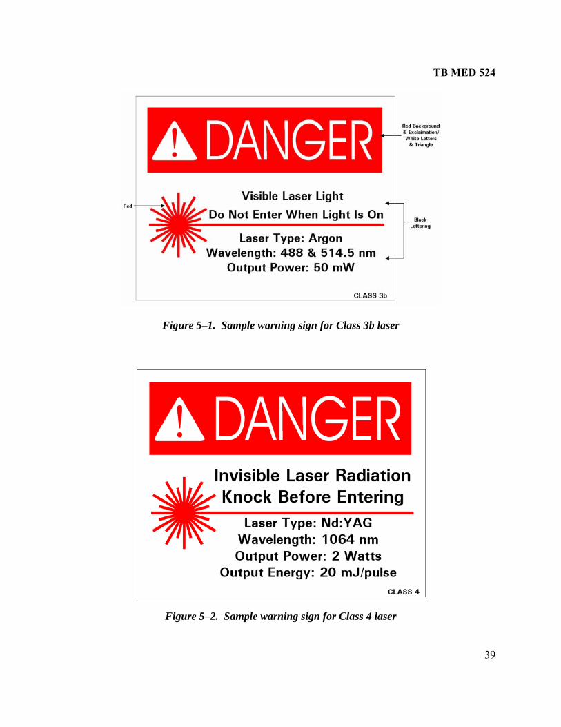
TB MED 524
39
gure 5–1. Sample warning sign for Class 3b laser
Fi
Figure 5–2. Sample warning sign for Class 4 laser

TB MED 524
40
um aluminum
Figure 5–4. Sample warning sign for Class 4 neodymium:yttrium aluminum garnet laser
Figure 5–3. Sample warning sign for Class 4 double neodymium:yttrigarnet laser

TB MED 524
41
Figure 5–5. Sample warning sign for Class 4 carbon dioxide laser

TB MED 524
42
Figure 5–6. Sample International Electrotechnical Commission warning sign

TB MED 524
43
Figure 5–7. Sample warning sign for temporary laser controlled area
5–5. Education and training Education and training will be provided to laser workers commensurate with the specific lasers that they work with and the highest class lasers to which they may be exposed. The training may be in the form guidelines, SOPs, operato e LSO. 5–6. Authorized personnel Operation, maintenance, and/or service on Class 3b or Class 4 lasers will be performed by authorized personnel only. Enclosed Class 3b or Class 4 lasers will be maintained or serviced by authorized personnel only if these procedures allow for potential exposure to laser radiation levels in excess of the appropriate MPE. 5–7. Beam alignment procedures a. Beam alignment procedures have been shown as the basis for many eye overexposures. Although there are no alignment procedures for laser optical systems (for example, mirrors, prisms, and lenses) that employ Class 2 and Class 3a lasers, it is always good laser safety practice to avoid laser eye exposures that exceed the MPE. b. A guideline or SOP that outlines a particular laser’s alignment procedures must be approved by the LSO for all Class 3b and Class 4 lasers. Class 3b and Class 4 laser alignment shall be performed so that the primary beam and any specular or diffusely reflected beams do not expose the eye to laser radiation levels above the MPE. It is a good laser safety practice to use Class 1 or Class 2 lasers for alignment of Class 3b and Class 4 laser optical systems.
of an appropriate laser safety course or may be administered through r’s manuals, manufacturer’s literature, or other material provided by th

TB MED 524
44
This page intentionally blank

TB MED 524
45
CHAPTER 6
RANGE CONTROL AND OUTDOOR APPLICATIONS
6–1. Force-on-Force exercises a. The personnel hazards associated with military exercises involving high-powered lasers (listed in appendix H, table H–1) that are intentionally pointed at soldiers by other soldiers during simulated combat are varied and specific to the particular testing environment. During such exercises, control measures such as those outlined in guideline D–8 (appendix D) that will protect soldiers as a result of injury from emitted optical radiation require careful planning to avoid injury and is beyond the scope of this section. b. These types of exercises with Class 3B and Class 4 lasers should not be attempted without specific guidance from USACHPPM. Consult the USACHPPM LORP when planning these exercises so that appropriate laser safety precautions can be developed for that specific exercise. c. Paragraph D–10 provides guidelines and safety practices when using lower-power training laser systems in two-sided exercises and provides examples of the controls necessary for higher-power lasers. To request the LORP’s servATTN: MC 010-5403;
electronically at http://chppm-
ices, please contact: Commander, USACHPPM, HB–TS–OLO, 5158 Blackhawk Road, Aberdeen Proving Ground, MD 21
call DSN 584–3932, commercial (410) 436–3932; orwww.apgea.army.mil/laser/laser.html.
en ith respect to those types of weapons will be more than sufficient to provide most aspects of the
the direct laser beam or a laser beam reflected from
jury with permanent impairment of vision can
ces,
.
6–2. Background a. The laser system, except for its inability to penetrate targets, can be treated like a direct-fire, line-of-sight weapon such as a rifle or machine gun. Thus, the hazard control precautions takwsafe environment required for laser use. This chapter will provide a general understanding of laser range use. For further and more detailed information, see AR 385–63 and MIL–HDBK–828A. b. The hazard from the laser devices listed in table H–1 is generally limited to exposure ofunprotected eyes of individuals within thespecular (mirror-like) surfaces. Serious eye inresult to unprotected personnel exposed to the laser beam. The hazards for exposure of the skin are small compared to exposure to the eye; however, personnel should avoid direct exposure tothe unprotected skin within the skin hazard distance if one exists. At normal operating distanthese lasers will not burn the skin or cause physical discomfort but can result in eye injury c. Essentially, the laser beam travels in a straight line so it is necessary to provide a backstop, such as a hill, behind the target during laser firing as depicted in figure 6–1. Normally, the

TB MED 524
46
OHD is the distance from the laser to the appropriate backstop. Calculated NOHDs often xtend beyond 10 km, and the use of magnifying optics within the beam could extend the NOHD
considerably. An official NOHD for specialized use by installation range control officers (see table H–1).
Figure 6–1. Laser range terrain profiles with backstop
d. Every object the laser beam strikes will reflect some energy back toward the laser. In most cases, this energy is a diffuse reflection and is not hazardous; however, certain flat shiny reflecting surfaces (specular) should be avoided as targets to prevent hazardous laser radiation from being reflected (see figures 6–2 and 6–3). Operators of most approved fielded military laser systems are protected against specular reflections from their laser system (see table H–1). For middle- and far-infrared laser wavelengths, specular reflections can occur from flat, smooth surfaces that appear diffuse.
Ne
is established by USACHPPM

TB MED 524
47
Figure 6–2. Diffuse and specular reflections
Figure 6–3. Specular reflection from water or horizontal flat glass on laser range
6–3. Laser systems a. A list of fielded military laser systems with descriptions can be found in appendix H. Table H–1 lists several common Army fielded systems. Several systems, such as the Army/Navy/Ground, Vehicular Visible (AN/VVG)–2, are entirely phased out of the U.S. Army inventory. They may, however, be found in foreign militaries. b. These ruby laser rangefinders (LRFs) are the most hazardous lasers to the eye at close range. These lasers not only pose a hazard from intrabeam viewing of the direct beam but also from viewing specular and diffuse reflections (see figure 6–4). The NOHDs and ODs should only be used as a general guideline. Specific questions can be addressed to the USACHPPM LORP.

TB MED 524
48
Figure 6–4. Reflected intrabeam viewing
(1) Direct fire sim such as MILES, are usually low-powered diode systems. These lasers are designed to be pointed at personnel uring combat training. Although there is relatively little risk of eye injury from these lasers, the
pment.
These laser systems can be far more harmful to the eye than laser aining devices such as the MILES laser simulators. Consequently, fire-control lasers require
control measures to prevent serious eye injury. A sample list of control measures for laser operators is provided in appendix F. Sample safety guidelines can be found in Appendix D. (3) Laser safety summary. Table H–1 summarizes current laser safety information pertaining to the most common fire-control laser systems. The NOHDs for unaided viewing and aided viewing, viewing the beam with NOHD-magnifying (NOHD-M) optics, such as a pair of binoculars, are also listed in table H–1. The laser beam is normally terminated within a controlled area at a distance less than the NOHD.
ulators. Lasers used to simulate direct fire from weapons,
dbeams sometimes exceed the MPE within a few meters (less than 10 m for the unaided eye). All users of MILES equipment should receive laser safety training prior to the use of the equiAlthough the use of these lasers has been determined to be safe during field training, safety measures should be taken to prevent exposure to the beam during maintenance and checkout procedures. (See paragraph D–4, appendix D, for safety guidelines). (2) Fire control laser systems. LRFs and laser designators (LDs) are used to determine target distance and to mark targets. tr

TB MED 524
49
d. Buffer zones. Each buffer zone gives the minimum angular size to be added to the edges of the backstop to ensure beam termination. By ensuring that an adequate backstop is present, laser energy is prevented from leaving the controlled area. If a target approaches the skyline with no vertical buffer zone, laser operation should cease unless the airspace is controlled out to the single-pulse NOHD. e. Laser protective eye devices. Table H–1 summarizes the OD requirements for intrabeam viewing with or without magnifying optics. Protective OD values for a single-pulse exposure are listed in the last column. OD is wavelength specific and may offer no protection at other wavelengths. At longer distances from the laser, the beam spreads out and becomes less harmful. 6–4. User instructions a. In addition to instructions on particular laser devices or simulators, training material required for classroom instructors and range personnel should include⎯ (1) Principles of reflection and refraction of light. (2) Personnel hazards (that is, biologic effects on eye and/or skin). (3) Guidelines or safety SOPs. (4) Preparation of laser ranges (for example, placement of targets and removal of specular surfaces). b. Laser safety training advanced in ividual training and to officers taking basi ourses as p t of basic weapons systems instruction. The classroom instructors must be knowledgeable in perator and crew aspects of laser safety. Hazard data for lasers as incorporated into the field manual (FM) on the related weapon system or on the laser component should be stressed. Proper channels for obtaining professional safety and medical assistance should be addressed during training. A train-the-trainer or user-level course in laser/optical radiation hazards is available from the USACHPPM LORP. c. Laser training filters may be available for some military laser systems. These filters reduce the output to levels that may be safe or require less control. For most military laser systems, eye protection is built into the aiming sight and protects the operator at the lasing wavelength. 6–5. Range boundaries a. Laser ranges used for the operation of Class 3b or Class 4 lasers must have warning signs posted the
nge r the
should be provided for enlisted students takingc c
daro
stating that the range is approved for laser use. These signs should be posted around perimeter at any access road and along areas where personnel could inadvertently entera
range. b. Additional warning signs must be posted during actual laser operations. An example of a typical laser range warning sign is shown in figure 6–5.
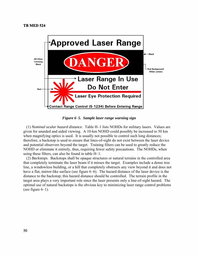
TB MED 524
50
TB MED 524
50
Figure 6–5. Sample laser range warning sign (1) Nominal ocular hazard distance. Table H–1 lists NOHDs for military lasers. Values are given for unaided and aided viewing. A 10-km NOHD could possibly be increased to 50 km when magnifying optics is h long distances;
erefore, a backstop is used to ensure that lines-of-sight do not exist between the laser device
not
e terrain profile in the
used. It is usually not possible to control sucthand potential observers beyond the target. Training filters can be used to greatly reduce the NOHD or eliminate it entirely, thus, requiring fewer safety precautions. The NOHDs, when using these filters, can also be found in table H–1. (2) Backstops. Backstops shall be opaque structures or natural terrains in the controlled area that completely terminate the laser beam if it misses the target. Examples include a dense tree line, a windowless building, or a hill that completely obstructs any view beyond it and does have a flat, mirror-like surface (see figure 6–6). The hazard distance of the laser device is thedistance to the backstop; this hazard distance should be controlled. Thtarget area plays a very important role since the laser presents only a line-of-sight hazard. The optimal use of natural backstops is the obvious key to minimizing laser range control problems (see figure 6–1).

TB MED 524
51
Figure 6–6. Sample range backstop (3) Buffer zones. The extent of horizontal and vertical buffer zones around the target area, viewed fro
as m the firing area, depends upon the aiming accuracy and stability of the laser device
h
p to
ere e values for
or platform. Vertical buffer zones are necessary when a line-of-sight exists to uncontrolled higground beyond the target or when downrange air space is not controlled to the NOHD (see figure 6–7). A vertical buffer zone must be maintained below the highest point on a backstothe target and above the lowest point on a backstop to the target area. The horizontal buffer zonecovers the distance to the left of the leftmost target and to the right of the rightmost target. The laser horizontal buffer zones could be included in lateral safety or ricochet areas on ranges whthe laser is used with live-fire weapons (see figure 6–8). Table H–1 lists buffer zoncurrently fielded laser systems.
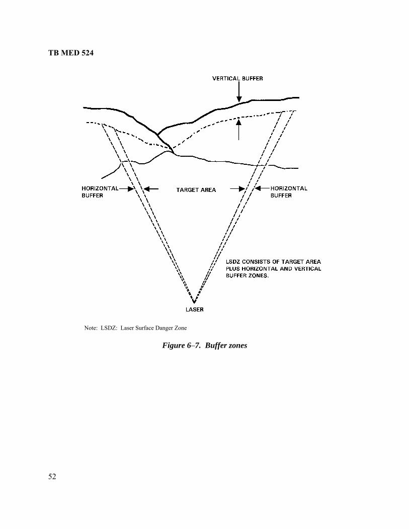
TB MED 524
52
Note: LSDZ: Laser Surface Danger Zone
Figure 6–7. Buffer zones
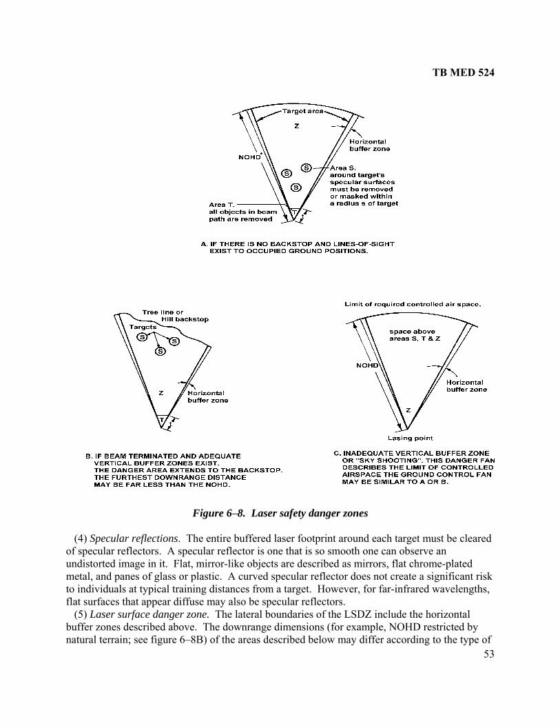
TB MED 524
53
Figure 6–8. Laser safety danger zones (4) Specular reflections. The entire buffered laser footprint around each target must be cleared of specular reflectors. A specular reflector is one that is so smooth one can observe an undistorted image in it. Flat, mirror-like objects are described as mirrors, flat chrome-plated metal, and panes of glass or plastic. A curved specular reflector does not create a significant risk to individuals at typical training distances from a target. However, for far-infrared wavelengths, flat surfaces that appear diffuse may also be specular reflectors. (5) Laser surface danger zone. The lateral boundaries of the LSDZ include the horizontal buffer zones described above. The downrange dimensions (for example, NOHD restricted by natural terrain; see figure 6–8B) of the areas described below may differ according to the type of

TB MED 524
54
device being used. Flat specular surfaces, visible from the firing line with field binoculars, should be removed within 30 m of each target. Table H–1 lists these downrange dimensions for current laser devices. Depending on the device(s) being used, the dimensions in table H–1 should be applied to the LSDZ in figure 6–8. Although the hazard of exposure to the skin is typically small, personnel should avoid direct exposure to the beam. Lasing at targets on the horizon (no vertical buffer zone) is permitted as long as air space is controlled to the NOHD for unaided viewing (see figure 6–8C). Operators should only aim at approved aerial targets. In the unusual case where there are no natural backstops available (for example, desert flats), the NOHD may extend out to extremely long ranges (for example, 25 km for a tank mounted LRF; see figure 6–8A). 6–6. Range control procedures The underlying concept of laser range safety is to prevent intrabeam viewing by unprotected personnel. This is done by locating target areas where no line-of-sight exists between lasers and uncontrolled, potentially occupied areas and by removing specular surfaces from targets. A step-by-step procedure for evaluating a range for possible laser use is as follows: a. Determine the extent of range boundaries (for example, NOHD and buffer zones, table H–1). b. Evaluate the potential hazards from specular surfaces, such as those from vision blocks, flat windows, and mirrors on target vehicles. Clear a 30-m area of specular reflectors around the target vehicles. Glossy foliage, raindrops, car bumpers, and curved auto glass are not considered to be flat specular surfaces that would create ocular hazards. If target areas have no flat specular surfaces, then range control measures can be limited to the control of the beam path between the laser and backstop. When retro-reflective targets are used, a hazardous specular reflection exists from the front surface of the reflector and, in addition, a specular reflection is aimed back toward the laser. c. Determine whether a hazardous diffuse reflection exists. Laser targets should be diffuse and not specular. Retro-reflective tape and plastic retro-reflectors (bicycle type) provide an enhanced diffuse refl d. Evaluate the stability of the laser platform t of lateral range control and the lateral constraints that shou traverse. Evaluate the need for the control of the elevation angle (for example, air space restrictions). e. Determine if personnel participating in the exercise will be using magnifying optics. The use of magnifying daylight optical devices to observe the target during laser operation is permitted if all specular reflective surfaces have been removed from the target area. However, if these surfaces cannot be removed, either appropriate laser safety filters in the optical train of the magnifying optics or laser protective eye devices are necessary. f. Determine the likelihood of personnel being present in the area of the laser beam (that is, ease of public access to the range). g. Determine the proper location of roadblocks and warning signs. Local guidelines or SOPs may provide for the placement of temporary signs during operation. Signs should be according to current Occupational Safety and Health Administration (OSHA) guidelines.
ection. . ine the exten
ld be placed upon the beam Determ

TB MED 524
55
h. Consider environmental conditions. Calm, smooth water, and clean ice can reflect the laser beams especially at a low angle of incidence. Consider these potential reflections when establishing target areas. Inclement weather and night operations require no additional precautions. i. The following are considerations to be taken into account regarding personnel who may be exposed: (1) Degree of training in laser safety of all individuals involved in the laser operation. (2) Reliability of individuals to wear eye protection if required. Individuals within the LSDZ, such as moving targets operators, must wear laser protective eyewear with curved protective lenses during laser firing. Eyewear must be approved for the wavelength of the laser device being fired. A laser filter designed to protect against one wavelength of laser may not protect against another. See tables H–1 and H–2 for the wavelength and OD required for current fielded devices. If more than one type of laser is used, the eyewear must provide sufficient protection at all operating wavelengths. For lasers of the same wavelength, the highest required OD will be used. (3) Expectation of individuals to be intentionally exposed to the laser light. (4) Number and location of individuals relative to the primary beam or reflections, and likelihood of unintentional exposure. 6–7. Image intensifiers a. Image intensifiers and thermal night sights provide some laser eye protection because there is no direct path to the eye. However, exposure to the eye is usually possible from lines-of-sight, which circumvent these devices. b. Some devices, such as the AN/PVS–6 Laser Infrared Observation Set (see appendix H), have not been designated as laser protective eye wear because a small possibility does exist that laser energy may enter the eye through open spaces around the tube mounts in the goggles. 6–8. Countdown A countdown is not required prior to firing in a range environment. The use of range flags, flashing lights, or temporary warning signs during lasing serves the purpose of notifying personnel when the laser is actually being used. (Range flags are also used for live-weapon firing.) 6–9. Communications
ommunications must be maintained with the target area at all times. Personnel downrange in
, lasing
t according to safety guidelines
Cthe target area shall be notified during laser operation to ensure that such personnel are wearing proper eye protection during times of actual lasing. If there is a loss of communicationsmust be stopped until communications are re-established 6–10. Operation outside of range area a. Maintenance shall be performed in a controlled environmenor SOPs associated with the particular laser system. The beam must be contained so that personnel are not exposed.

TB MED 524
56
the
e
rea to another within the range and is not engaged in tactical/operations
onducted in a controlled environment. ipped vehicle is stored or parked and is not engaged in tactical
und targets. At
ng the laser source directly or viewing specular surfaces illuminated by the laser.
le and near-infrared regions of the spectrum and having an output energy per pulse
protection that reduces the vision of aircrew personnel should be
ts, is encouraged when
ge.
to tion other than an authorized firing site.
.
b. Pre-fire checks that require operation of the laser can be made in a controlled area with laser beam terminated by an opaque backstop. Pre-fire checks that do not require operation of the laser but require use of the optics can be safely made in a controlled area with the opaqudust cover or ballistic cover removed. Operating procedures must ensure power to the laser isshut down. c. Tactical exercises can be conducted with the laser cover removed as long as the laser is inactivated. d. If possible, the laser exit port should be covered when⎯ (1) Any laser device or laser-equipped vehicle is traveling on public highways, range roads, ormoving from one ac (2) The laser device or laser-equexercises. 6–11. Laser operations from aircraft Guidelines are provided for operation of airborne LRFs and LDs aimed at gromost operational altitudes, airborne operations can cause ocular injury to ground personnel observi a. The target area should be clear of flat specular surfaces. The crew of the lasing aircraft should be instructed to visually check for possible specular items before laser operation by noting the location of standing water and the position of vehicles and buildings that may contain glass. b. Laser protective eyewear with curved filter lenses should be made available for personnel required to be in the vicinity of the target area during laser operation. The eye protectors should provide an OD appropriate for the operation at the laser wavelength. For LRFs and LDs emitting in the visibless than 0.1 J, an OD of 6 at the laser’s operating wavelength is adequate. Reduced ODs may be possible in specific instances. c. The use of eyediscouraged; other hazard controls should be used instead. If a laser beam is directly illuminating the aircraft (for example, by a ground-to-air LRF), eye protection for the aircrew isnecessary. Use of the laser protective visors, now available for all pilotraining with their lasers. These visors should not be relied on when the aircraft is the laser target since the visors were designed for combat use and not for training. d. The flight crew should only fire the laser at designated targets. e. All ground personnel should be instructed to assume that the laser is in operation at all timeswhenever the aircraft is firing on targets or is above an active ran f. The person in charge or operator should ensure that the laser system is secured and unablefire when the aircraft is in some loca g. The installation range control officer and local air traffic controllers should ensure that adequate danger zones are established and that strict control of traffic is maintained as necessaryThe range control officer will⎯

TB MED 524
57
sociated
hly brief all pilots prior to any mission within the laser danger area. The briefing
s used, and applicable local procedures. Whenever possible, each pilot assigned to a e
of
rget acquisition is prohibited within the 20-degree safety zone (figure 6–9). This safety nator, is
he designator to the target. k. The projection of the laser beam that irradiates the ground, ground-based, sea-based, or
l. Normally, laser beams are circular, diverge equally in all directions,
rojection on the target plus a buffer zone (see figures 6–7 and
etermine the laser footprint, see MIL–HDBK–828A.
or with a ground-based target
(1) Coordinate the mission with other activities within the laser operational area and furnish all required information to control tower operators and authorized ground control stations aswith the mission. (2) Thorougshould include the geography of the area, access and exit routes, limits of flight pattern, radio frequencietraining mission should make a dry run prior to the mission to become acquainted with thprescribed course and the test area. h. Laser operations should not be initiated unless appropriate buffer zones exist on all sidesthe target within the government-controlled property area. i. When the laser is directed into a target area that provides a positive, natural backstop (suchas, a hill or valley), the vertical buffer zone may easily be kept within range boundaries. Airspace downrange of intended targets must be controlled out to the NOHD when standing water exists in the lasing area. j. Tazone, a buffer angle around the line of sight between the target and laser desigestablished to prevent the weapon system from acquiring false targets due to false signals emanating along the beam path from t airborne targets is ellipticaand produce cone-shaped beams. The size of the beam depends on the initial beam diameter, divergence (beam spread), and distance (slant range) from the laser. The size of the laser footprint is the size of the beam’s p6–8). For scanning systems, the size of the beam includes all potential positions of the beam. The shape of the footprint depends on the slant angle. The slant angle is determined from the distance from the laser to the target and the relative altitudes. For information on how to d
Figure 6–9. Buffer zone for a laser designat

TB MED 524
58
tenance officer should clear all personnel located on site. Personnel should be
ceed those necessary to accomplish the task safely and efficiently. of a laser over an extended
).
6–12. Hangar, garage, and maintenance shop procedures a. All testing performed in shop areas will be strictly controlled with barriers and signs. b. In shop areas, the laser beam should be contained in an enclosure, expressly designed to contain all of the laser output, when feasible. c. The mainrestricted to those having an official interest in the test, and the number of personnel on site should not ex d. Personnel should conduct check tests requiring operation distance (that is, 100 m–1000 m) in unoccupied areas only under strict controls. One method for controlling the beam to a tightly controlled path is by the use of apertures located at 1 m and 10 m from the laser (figure 6–10
Figure 6–10. Laser maintenance test range
Note: The test range is established by limiting beam elevation and azimuth to ensure that the beam strikes a diffuse backstop; the beam path is above occupied areas
6–13. Inclement weather During periods of inclement weather, additional hazards may exist. During rain or snow, hazards from diffuse and specular reflections may exist within 1 m of the laser beam path. Wateror ice on flat, non-specular surfaces could create a specular reflection when the surface is wet. Additional safety precautions may be necessary to prevent these reflections, such as coveringoptical components. Electrical hazards may also be created when rain or s
flat now dampens
approach the MPE for a laser to produce hazardous visual interference effects. However, visual effects are possible with low-power lasers, such as laser
electrical connections. 6–14. Visual interference hazards a. General. Serious injury may result from accidents attributable to visible laser exposure that interferes with vision when personnel are performing critical tasks such as driving, flying anaircraft, or operating heavy equipment or machinery. Visual interference effects include dazzle, glare, startle, flash-blindness, or temporary visual impairment (see para 3–6). During the daytime, the laser irradiance must

TB MED 524
59
or laser pointers to illuminate police or other individuals may be illegal in
,
sion adiance multiplied by 683 is the illuminance. In terms of
instances, the MPE can be exceeded
Visual interference zones have been established where disruption
those
ding visual interference level
ndant
of the se tasks. These zones are specified in the
AA Order 7400.2D and ANSI Z136.6. (1) Normal zone. The normal zone encompasses all areas not included in the zones listed below. Personnel in this zone should not be exposed to levels above the MPE (see figure 6–11).
pointers or laser scopes for rifles, when a person is exposed at night or in a dark environment. Laser pointers should only be used by responsible individuals and not used as toys. The misuse of laser rifle sightssome districts. b. Visual interference levels. Three levels of laser visual interference are defined: sensitivecritical, and laser-free. These levels are based on visual sensitivity of the eye. The levels are provided as effective irradiance (that is, irradiance multiplied by the normalized photopic viresponse function). The effective irreffective irradiance, the sensitive level is 100 microwatt (μW)·cm-2; the critical level is 5 μW·cm-2; and the laser-free level is 50 µW·cm-2. In someeven when the visual interference level is not exceeded. When the MPE indicates more hazard, the evaluation is based on the MPE instead of the visual interference level. These levels correspond to the zones described in paragraph 6–14c. c. Visual interference zones. of critical visual tasks would create safety problems. Reduced ambient illumination, dazzle, startle, or distraction by visible laser beams creates indirect hazards at levels well belowknown to cause eye injury. The beam from a visible laser should not enter any visual interference zone when the irradiance is greater than the corresponunless adequate protective means are employed to prevent personnel exposure. Protective means should be used to protect personnel and pilots when a visual interference level could be exceeded. Aircrews may be protected either by the use of protective eyewear or by systems designed to terminate the laser beam whenever an aircraft approaches the beam path. Reduprotective systems are advisable in locations noted for heavy air traffic (see appendix H). The LSO/RSO should be aware of the location of Federal Aviation Administration (FAA)-defined zones and may designate other areas or zones that may be classified as critical or sensitive. Assignment of zones depends on the difficulty of the expected tasks and the consequenceslaser beam producing an error in the performance of thoF

TB MED 524
60
Note: nW/cm2: nanoWatt per square centimeter
Figure 6–11. Visual interference flight zones (2) Sensitive zone. The sensitive zone encompasses the area on the ground or volume of airspace where expo l sks but not jeopardize safety. T (3) Critical zone. asses the area on the ground or volume of airspace where interference with c bile or aircraft at night,
ould jeopardize safety (see figures 6–11 and 6–12).
sure to intense visible beams would interfere with criticahe local FAA office determines the sensitive zone.
The critical zone encomp
ta
ritical visual tasks, such as operating an automow

TB MED 524
61
Figure 6-12. Critical and laser free zones
(4) Laser free zone. The laser free zone encompasses the volume of airspace immediately next to the runway. When laser beams in this zone could exceed the laser free level, redundant layers of protective mechanisms are advisable since visual interference by a laser beam in this zone would be very serious (see figures 6–11, 6–12, and 6–13).

TB MED 524
62
ses, however, the duration of an nintentional encounter cannot be accurately determined since the persons are operating vehicles
traveling at some speed (auto or air traffic). The duration of the visual interference may be less than 0.25 s due to flight intercept geometry or equipment design. In this document, visual interference is based on effective irradiance for exposures exceeding 0.25 s (see para 6–14b). For exposure durations less than 0.25 s, the visual interference level is based on the effective radiant exposure for 0.25 s (see table E–1). e. Protection distances. The distances beyond which the effective irradiance is below the MPE, critical level, sensitive level, or laser free level correspond to the NOHD, critical distance, sensitive distance, or laser-free distance. The same formula for computing NOHDs may be used to calculate these other distances by substituting the visual interference levels for the MPE (see appendix B). Appropriate protective mechanisms should be employed if the laser beam intercepts a visual interference zone within the corresponding protection distance.
Note: AGL: above ground level
Figure 6–13. Laser free zone d. Visual interference duration. The degree of visual interference that is caused by a laser beam depends on the duration of the effect. In most cau

TB MED 524
63
CHAPTER 7
LASER EYE PROTECTIVE DEVICES
7–1. Background a. The need for laser eye protective devices has been demonstrated for all regions of the optical spectrum. Laser eye protective devices should only be used when engineering and administrative controls do not adequately control the hazard. It has been known since the early 1960s that visible and near-infrared laser wavelengths (400 nm–1400 nm) present a unique hazard to the retina of the eye due to the focusing ability of the cornea and lens. In this retinal hazard region, the eye is about 100,000 times more vulnerable to injury than the skin. In spectral regions outside of the retinal hazard region, the eye and skin are almost equally vulnerable to injury. b. In 1962, Dr. Harold Straub of the U.S. Army Harry Diamond Laboratory, developed the first laser eye protector by installing a two- by four-inch, blue-green glass (Schott-type BG–18), filter plate into a standard acetylene welding goggle frame. Today, laser protective eyewear is available from several commercial sources in several designs; spectacles cover all types with opaque side shields and cover all types with somewhat transparent side shields (figure 7–1). Technical information on laser protective devices is available from USACHPPM LORP website at: http://chppm-www.apgea.army.mil/laser/laser.html. c. Several factors should ear is necessary and, if
, selecting the proper eye nclude the wavelength(s)
ters placed in (or clipped onto)
ptical sights; or laser protective filter windows, screens, curtains, or barriers.
be considered in determining whether eyewwear for a specific situation. These factors iso
the eyewear is designed to protect against, the required OD, the visual transmittance of the eyewear, and the task being performed. d. A note on terminology is now appropriate. Laser protective eyewear or laser eye protectors refer to goggles, spectacles, or visors worn by the individual. Laser eye protective devices is a
eneral term applicable to eye protectors; laser protective filgo
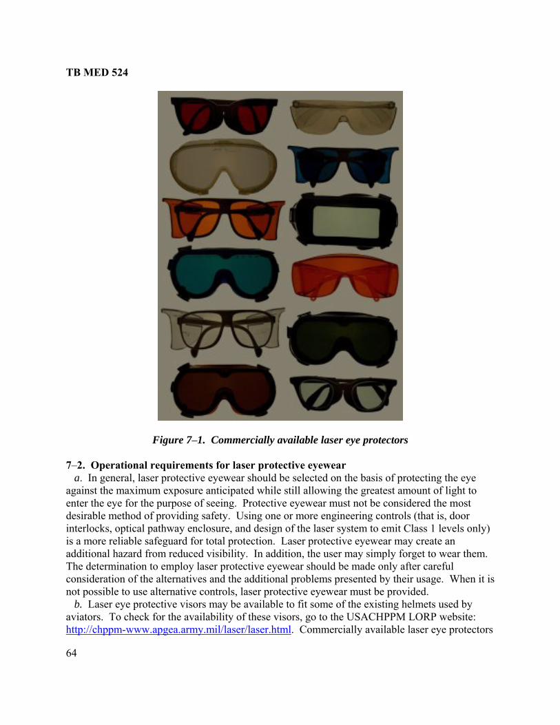
TB MED 524
64
Figure 7–1. Commercially available laser eye protectors
7–2. Operational requirements for laser protective eyewear a. In general, laser protective eyewear should be selected on the basis of protecting the eyagainst the maximum exposure anticipated while still allowing the greatest amount of light to enter the eye for the purpose of seeing. Protective eyewear must not be considered the most desirable method of providing safety. Using
e
one or more engineering controls (that is, door ly)
hen it is
b. Laser eye protective visors may be availabl to fit some of the existing helmets used by aviators. To check for the availability of these visors, go to the USACHPPM LORP website: http://chppm-www.apgea.army.mil/laser/laser.html
interlocks, optical pathway enclosure, and design of the laser system to emit Class 1 levels onis a more reliable safeguard for total protection. Laser protective eyewear may create an additional hazard from reduced visibility. In addition, the user may simply forget to wear them. The determination to employ laser protective eyewear should be made only after careful consideration of the alternatives and the additional problems presented by their usage. Wnot possible to use alternative controls, laser protective eyewear must be provided.
e
. Commercially available laser eye protectors
TB MED 524
65
are normally not recommended for fligh d hazards resulting from loss of peripheral vision, reduced visual transmission, and degraded color contrast from most types of goggles, may outweighForce-on-Force exercis directed toward the aircraft, then aviators are required to wear high-visibility laser eye protectors. Side shields are required for the aircrew when the aircraft is a tar or a laser test.
c. ored vehicle crews during training exercises are not required to wear
dley s.
gth.
procedure of removing specular targets from range target areas eliminates the
.
ions are possible. Eye protection is
ive r visors; Head Gear Unit, 56th version, Pilot (or HGU
and development laboratories, testing facilities, or maintenance shops. If there are any concerns, consult with the USACHPPM LORP before using these eye protectors on training ranges. g. Recommendations for operational hazard controls and eye protection requirements for specific Army laser systems are given in table G–1. h. The Military Eye Protection System program is under development to replace the BLPS, SPECS, and SWDG. The concept is to provide more protection with better visibility. 7–3. Other laser protective devices a. Built-in laser eye protective filters. Questions concerning specific ODs or protective parameters of a laser protective device should be referred to the program manager of that system. Table H–1 lists systems with built-in eye protective filters⎯
t crews. The adde
the protection afforded by such eye protectors. However, during a e or if a hazardous specular reflection is likely to be
get f At present, armpersonal eye protection. If an armored vehicle is the target in laser tests or exercises, all exposed personnel in the target area are required to wear laser eye protectors. Currently, all M2 BraFighting Vehicles manufactured after February 1991 have laser protective filters in all opticThe M1 tanks manufactured after August 1988 have laser protective filters built into all optics for protection against the Neodymium:Yittrium Aluminum Garnet (Nd:YAG) laser wavelen d. In test and training activities, eye protection with curved surfaces is required for personneldownrange within the laser beam target area and for other personnel within the NHZ if the target area cannot be cleared of specularly reflective surfaces. However, the more desirable hazard control requirement for eye protection for all but the personnel within the target area. Potentially hazardous specular reflections can exist to significant distances from flat-lens surfaces. Hence, the curved filters are far more desirable than flat-lens filters. e. For indoor shop or laboratory environments, eye protection may be required for Class 3b or Class 4 lasers. Class 4 lasers that are diffuse reflection hazards require laser eye protectionDuring alignment procedures for Class 3b lasers, or Class 4 lasers that are not diffuse hazards, eye protection is required if uncontrolled specular reflectnormally not required for Class 1, Class 2, or Class 3a lasers. f. Army laser protective eyewear is currently being provided by Special protective eyewear, cylindrical system (SPECS); Ballistic and laser protective spectacles (BLPS); Sound protecthelmet, 4th version (SPH–4) aviator lase –56P) Apache laser visor and laser glasses; M17 and M40 laser/ballistic protective gas mask outserts; and Sun, wind, and dust goggles (SWDG) with ballistic/laser lenses. Some of these products are still under development and not yet available through National Stock Numbers (NSN). These systems are not to be used in Force-on-Force training, research

TB MED 524
66
(1) M22, M24, and M25 binoculars. Users of these devices are protected against all U.S. military LRFs, LDs, and some other types of lasers. (2) Vision blocks. M1 tanks have protection against the same type of laser used in the M1. Bradley vehicles may also have protection against the same type of laser used in the Bradley. (3) Sighting optics. Day-magnifying optics used to point LRFs and LDs have laser protection against the same type of laser. b. Screens, barriers, and curtains. These types of laser protective devices are used in industrial laser material processing and some laboratory and medical environments to control the laser exposure. c. Night vision devices. These devices provide multi-wavelength protection because soldiers do not view the battlefield directly. Exposure to lasers may produce temporary or permanent damage to the devices. Night vision devices are not recommended for use as laser eye protective devices because they do not provide adequate side protection. For specific information, contact the program manager for that system. d. Dynamic laser eye protective devices. A program has been funded by DOD to develop devices that protect against a variety of visible and near-infrared laser wavelengths simultaneously and are triggered upon exposure to the laser. They are extremely difficult to manufacture and rely on technologies that dynamically limit laser transmissions. These devices are not yet available. 7–4. Laser eye protective device parameters a. Technical factors. The technical factors that must be considered before purchasing laser safety eyewear are― (1) Wavelength. (2) OD with and/or without magnifying optics. (3) Laser power or energy. (4) Visible transmission of eyewear. (5) Laser filter da b. Other factors. Other factors that must be considered before purchasing laser safety eyewear
ye protection
mage threshold.
are⎯ (1) Field of view provided by the design. (2) Flatness of laser eye protective filter. (3) Side shield requirements. (4) Availability of prescription lenses or sufficient goggle frame size to permit wearing spectacles inside the goggle. (5) Comfort of goggle design. (6) Ventilation ports to prevent fogging. (7) Effect upon color vision. (8) Impact resistance. c. Wavelength. Laser eye protective devices are highly wavelength dependent. Ethat provides attenuation at one laser wavelength may provide no protection at other wavelengths. For instance, a doubled Nd:YAG laser may emit two wavelengths: 532 nm and
TB MED 524
67
on
itting
can be described as having
r
ut
in ighting in
ate OD at the laser wavelengths should not be sacrificed le
1064 nm. If you provide protection only at the 532 nm wavelength, relatively little protectimay be provided at the 1064 nm wavelength. d. Optical density. OD is a parameter for specifying the attenuation afforded by a transmmedium. Since laser beam irradiances may be a factor of a thousand or a million above safe exposure levels, percent transmission notation can be tedious. (1) For instance, goggles with a transmission of 0.000001 percent an OD of 8.0. OD is a logarithmic expression and is described by the following:
OD = log10 (Mi/Mt) (1)
Where: Mi is the power of the incident beam and Mt is the power of the transmitted beam. (2) Thus, a filter that attenuates a beam by a factor of 1,000 or 103 has an OD of 3, and one that attenuates a beam by 1,000,000 or 106 has an OD of 6. The OD of two highly absorbing filters stacked together is essentially the sum of two individual ODs. Calculating the required OD (ODreq) for a particular laser device requires knowledge of the output power or energy. Focommercially available lasers, the OD may already be calculated. For military lasers, the USACHPPM LORP calculates the OD for these lasers. When optical aids are not used, the following relationship may be used when radiant exposure (H) and irradiance (E) are averaged over the limiting aperture for classification:
ODreq = log10 (E or H)/MPE (2)
Where: the radiant exposure (E) or irradiance (H) is divided by the MPE.
(3) When the entire beam could enter a person’s eye, with or without optical aids, the following relationship is used:
ODreq = log10 [Φ0 or Q0/AEL] (3)
Where: AEL is the accessible emission limit (that is, the MPE multiplied by the area of the limiting aperture) and Φ0 and Q0 are the radiant power or energy, respectively.
e. Visible transmittance of eyewear. Since the purpose of laser eye protectors is to filter othe laser wavelengths while transmitting as much of the visible light as possible, visible (or luminous) transmittance should be considered. A low visible transmittance (usually measured ercent) creates problems of eye "fatigue" and may necessitate an increase in ambient lp
laboratory situations. However, adequfor improved luminous transmittance. For nighttime viewing conditions, the effective visibtransmittance will be different since the spectral response of the eye is different. Figure 7–2 shows the scotopic (night vision) and photopic (daylight vision) responses of the eye. From

TB MED 524
68
- er photopic transmission values than red or
figure 7–2, night vision peaks around 500 nm and daylight vision peaks around 560 nm. Bluegreen filters, therefore, have higher scotopic and loworange filters.
Figure 7–2. Relative spectral luminous efficiency (normalized) curves for
photopic (daylight) and scotopic (night) vision
m f. Laser filter damage threshold (maximuhe laser rad
irradiance). At very high-beam irradiances, filter iation can be damaged. It, therefore, becomes
electric coatings. Irradiances from CW lasers, which would hat would present a serious fire hazard, and therefore, ot be permitted in the area of such lasers. Figure 7–3
aser filters from high-beam irradiances.
materials that absorb or reflect tnecessary to consider a damage threshold for the filter. Typical damage thresholds from q-switched, pulsed laser radiation fall between 10 and 100 J·cm-2 for absorbing glass, and
-21 to 100 J·cm for plastics and dicause filter damage, are in excess of those t
nel should nneed not be considered. Personge to lshows examples of dama

TB MED 524
69
Figure 7–3. Examples of damage to laser protective devices g. Laser protection devices. Figure 7–3 shows damage to laser protective devices. The orgoggle (example A) has damage from a Q-switched pulsed doubled Nd:YAG laser. The bluegreen spectacle (example C) was also damaged by a Q-switched pulsed Nd:YAG laser. The clear spectacle (example E) was damaged with a CW carbon dioxide laser. The two pairs of goggles (examples B and D) on the right are identical. Neither have any laser damage, but the ottom goggle has become completely opaqu
ange -
e. Some organic dyes have been known to change haracteristics over a period of
h. Saturable absorption. In s e shown to have den occurs when the amo ilable for
rrent der
ditions. Commercial laser eye protectors are also required to be sted for saturable absorption.
7-5. Selecting appropriate eyew
threshold for the
s.
rs
bc time.
ome rare instance ctive filters wers, protesities less than specified under high irradiance levels. Saturable absorption
nt of laser energy entering the filter is high enough to saturate the dye avauabsorption, thus allowing an increased level of laser energy to pass through the filter. Cumilitary laser eye protectors (for example, BLPS, SPECS) have met OD requirements unaturable absorption testing cons
te
ear a. Determine the laser wavelength(s) and the required OD. For fielded military laser systems,see table H–1. Ensure that the maximum exposure does not exceed the damagefilter as explained in paragraph 7–4d. There are a variety of designs available, ranging from spectacle types to heavy-duty, cover-all goggles. Some frames meet impact safety requirementIndividual requirements may necessitate choosing a particular type of design. In most military applications, it is generally recommended that filter surfaces be curved so that incident beams are reflected in a manner that reduces the beam irradiance rapidly with distance from the surface. b. There are basically two methods for blocking laser wavelengths. The filters are either designed to selectively absorb or reflect the laser energy. The absorption method uses colored glass or plastic, and the reflective method uses dielectric or holographic coatings. Hybrid filtecombine these two technologies.
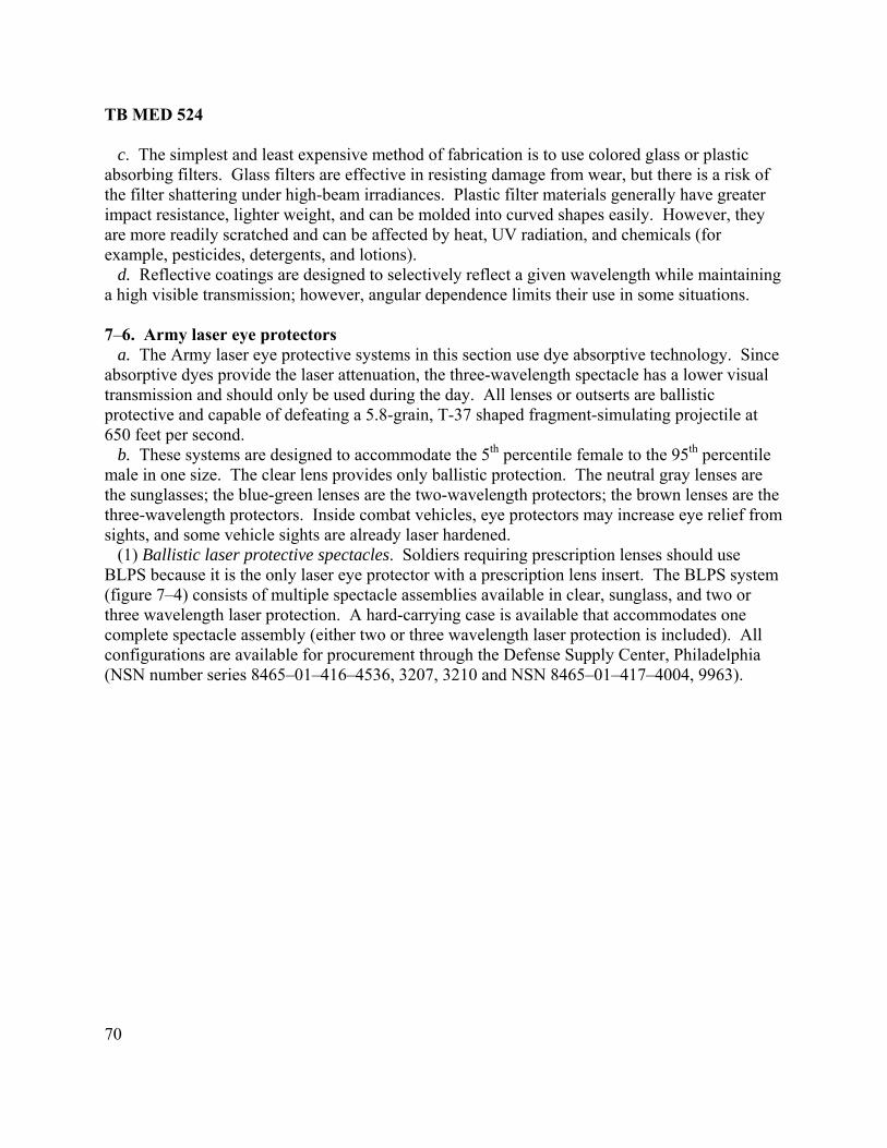
TB MED 524
70
ring under high-beam irradiances. Plastic filter materials generally have greater pact resistance, lighter weight, and can be molded into curved shapes easily. However, they
are more readily scratched and can be affected by heat, UV radiation, and chemicals (for example, pesticides, detergents, and lotions). d. Reflective coatings are designed to selectively reflect a given wavelength while maintaining a high visible transmission; however, angular dependence limits their use in some situations. 7–6. Army laser eye protectors a. The Army laser eye protective systems in this section use dye absorptive technology. Since absorptive dyes provide the laser attenuation, the three-wavelength spectacle has a lower visual transmission and should only be used during the day. All lenses or outserts are ballistic protective and capable of defeating a 5.8-grain, T-37 shaped fragment-simulating projectile at 650 feet per second. b. These systems are designed to accommodate the 5th percentile female to the 95th percentile male in one size. The clear lens provides only ballistic protection. The neutral gray lenses are the sunglasses; the blue-green lenses are the two-wavelength protectors; the brown lenses are the three-wavelength protectors. Inside combat vehicles, eye protectors may increase eye relief from sights, and some vehicle sights are already laser hardened. (1) Ballistic laser protective spectacles. Soldiers requiring prescription lenses should use BLPS because it is the only laser eye protector with a prescription lens insert. The BLPS system (figure 7–4) consists of multiple spectacle assemblies available in clear, sunglass, and two or three wavelength laser protection. A hard-carrying case is available that accommodates one complete spectacle assembly (either two or three wavelength laser protection is included). All configurations are available for procurement through the Defense Supply Center, Philadelphia (NSN number series 8465–01–416–4536, 3207, 3210 and NSN 8465–01–417–4004, 9963).
c. The simplest and least expensive method of fabrication is to use colored glass or plastic absorbing filters. Glass filters are effective in resisting damage from wear, but there is a risk of the filter shatteim

TB MED 524
71
oldiers
The
ng
516, 4628, 4631, 4634, 4632, 4627).
Figure 7–4. Ballistic and laser protective spectacles
(2) Special protective eyewear, cylindrical system. SPECS (figure 7–5) is designed for swho do not require prescription lenses. The SPECS system consists of a lens carrying browbar, interchangeable spatula and cable temples, a nosepiece, and four interchangeable lenses. temples are capable of panoscopic tilt adjustment for maximum fit, comfort, and acceptance. Ahard-carrying case is available that can accommodate a complete spectacle assembly consistiof a frame and two lenses. Configurations are available for procurement through the Defense Supply Center, Philadelphia (NSN number series 8465–01–416–4626, 4629, 4630, 4633, 4635, 8
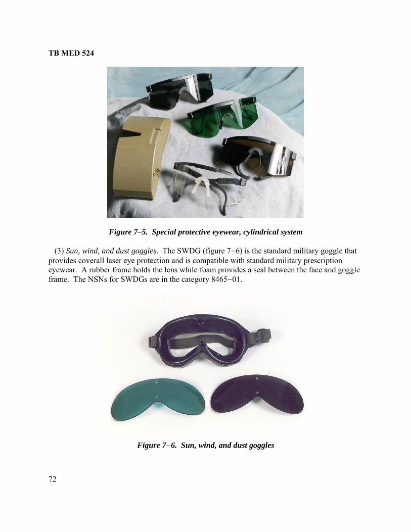
TB MED 524
72
Figure 7–6. Sun, wind, and dust goggles
Figure 7–5. Special protective eyewear, cylindrical system
(3) Sun, wind, and dust goggles. The SWDG (figure 7 6)– is the standard military goggle that provides coverall laser eye protection and is compatible with standard military prescription eyewear. A rubber frame holds the lens while foam provides a seal between the face and goggle frame. The NSNs for SWDGs are in the category 8465–01.

TB MED 524
73
(4) Mask, chemical-biological, M40/M42 series laser/ballistic outsert. The laser ballistic outsert (figure 7–7) can be purchased as an additional authorized list item for the M40 and M42 series mask. However, the laser/ballistic outsert is not compatible with the Red Hot mode of the thermal sight of the Bradley fighting vehicle. The NSN for the laser/ballistic outsert is 4240–01–434–1503.
Figure 7–7. M40/M42 gas mask laser/ballistic outsert 7–7. Commercial sources of laser eye protectors For a current listing o M LORP Laser Link webpage at: http://chppm-www.apgea.army.mil/laser/links/links.html
f laser eye protector manufacturers, see the USACHPP.
arious types of military laser eye protectors.
7–8. Inspection and testing of laser eye protective devices a. Eye protection should be checked periodically by the user for proper fit, good visibility, cracks, and discoloration. b. The measurement of eye protection filter ODs is difficult. Testing at high ODs can result inthe destruction of the filter. Because of these problems, there is no requirement that the OD ofprotective devices be periodically checked. The USACHPPM LORP has the capability of testingthe OD and environmental stability of v

TB MED 524
74
This page intentionally left blank

TB MED 524
75
CHAPTER 8
NONBEAM HAZARDS
8–1. Introduction a. In addition to direct hazards to the eyes and skin associated with exposure to the laser beam, it is also important to address other nonbeam hazards associated with the use of lasers (for example, cryogenics, flash lamps, chemicals, electrical, ionizing radiation, and UV hazards). b. These hazards, such as electrocution, can be life threatening. As a result, the hazards discussed in this chapter require use of control measures different from those discussed in chapter 5. c. Because of the diversity of these potential hazards, the LSO/RSO may employ safety, health physics, and/or industrial hygiene to aid in the control of these hazards. The following are
eneral guidelines: (1) Design the dev sonnel to nonbeam
azards. /or PPE when nonbeam hazards cannot be
rking hours or in isolated reas.
azard associated with the laser involves electricity. There have
als exposed can be equipment installers, users, technicians, and uninformed members of the public. b. Electrical safety requirements are imposed upon laser devices, systems, and those who work with them by the U.S. Department of Labor, OSHA, the National Electrical Code (NEC®) (National Fire Protection Association (NFPA®) 70) and related state and local laws and regulations. (NEC® and NFPA® are registered trademarks of the National Fire Protection Association, Quincy, MA.) 8–3. Prevention of electrical shock a. The following are general precautions: (1) Avoid wearing rings, metallic watchbands, and other metallic objects. (2) Use only one hand when working on a circuit or control device. (3) Never operate electrical equipment when hands, feet, and/or body are wet, perspiring, or while standing on a wet floor.
gice or control the environment to prevent exposure of per
h (2) Provide appropriate administrative controls andeliminated by design. (3) Consider the use of the “buddy system” especially after normal woa 8–2. Electrical hazards a. The most common lethal hbeen several fatal accidents associated with lasers due to electrocution. Injuries have occurred when commonly accepted safety procedures were not followed as when individuals were working with dangerous, high-voltage components of a laser system. Exposures can occur when equipment covers are removed as during maintenance and/or service. Those individu

TB MED 524
76
(4) Treat all surfaces as conductive and grounded unless covered with a well-maintained, dry bber matting of a type suitable for your electrical work.
(5) Provide a non-conductive tick, or insulated pole suitable for freeing a victim from a live conductor. (6) Cardiopulmonary resuscitation (CPR) training should be provided for personnel routinely working with high voltage. (7) Have an automated external defibrillator available. b. Safe design and installation practices for high-power lasers can be found in MIL–STD–882D, MIL–STD–1425A, and the NEC. The following is a list of user precautions when servicing or maintaining high-power lasers, which employ high-voltage: (1) Ensure that fault-current-limiting devices, such as fuses or resistors, are capable of clearing or dissipating total energy. (2) Provide a grounded metal enclosure that is locked and/or interlocked. (3) Enclose exposed terminals or electrical contacts. (4) Provide suitable enclosures and barriers that protect against projectiles, such as flash lamp explosions. (5) Keep combustible materials away from electrical contacts, capacitors, or high-power laser beams. (6) Ensure capacitors are discharged before opening any access door. (7) Place shorting straps at each capacitor during maintenance while capacitors are in storage. (8) Provide reliable grounding, shorting, and interlocking. (9) Ensure that high-voltage sources are properly labeled. (10) Provide manual grounding equipment that has the connecting cable visible for its entire length. (11) Supply safety devices such as safety glasses, rubber gloves, and insulating mats. (12) Provide metering, control, and auxiliary circuits that are protected from possible high potentials even during fault conditions. (13) Inspect routinely for deformed or leaky capacitor containers. (14) Provide a grounding stick that has a discharge resistor at its contact point and a ground cable attached to ground. Such a grounding stick should not be used to ground an entire large bank of capacitors. Large-capacity shorting bars, with resistors, should be used. Final assurance of discharge should be accomplished with a solid-conducting-grounding rod. c. The following potential problems have frequently been identified during laser facility audit: (1) Uncovered electrical terminals. (2) Improperly insulated electrical terminals. (3) Hidden "power-up" warning light. (4) Lack of personnel trained in current CPR practices or lack of refresher training. (5) "Buddy system" not being practiced during maintenance and service. (6) Improperly grounded laser equipment. (7) Excessive wires and cables on floor that create fall or slip hazards.
ru
object such as a rope, dry wooden s
TB MED 524
77
8–4. First-aid procedures for electrica a. Before touching a victim of electric shock, the circuit should be de-energized or the victim should be freed from the live con onconductive object such as a rope, dry wooden stick, or insulat b. It is recommended that one of these nonconductive devices be provided near each high-
oltage power supply (for example, in each research, development, testing, and evaluation b rocedures appropriate to the victim's condition should be started immediately.
se to
when t
be released in any given situation, it is known that contaminants, including new
sure ed according to federal, state, and local requirements.
the concentration of LGAC to acceptable levels. They are exhaust ventilation,
n. Whenever possible, recirculation of LGAC should be avoided. Use of
that all personnel exposures to hazardous concentrations of LGAC are maintained at or elow the allowable levels specified by OSHA, the National Institute for Occupational Safety
e American Conference of Governmental Industrial Hygienists
s ted.
er
diately
emove the individual from the contaminated environment as quickly a buddy system and be provided with adequate self-
taminated atmosphere. If the person has stopped breathing elp.
) mponents such as power supplies, discharge lamps, and plasma
l shock victims
ductor by using some suitable ned pole.
vla oratory). CPR p 8–5. Laser-generated air contaminants a. Some applications of high-power lasers, especially in materials processing, can give rirespiratory hazards. Laser welding, cutting, and drilling procedures can create potentially hazardous fumes and vapors. Laser-generated air contaminants (LGAC) may be produced certain Class 3b and Class 4 beams interact with matter. While it is difficult to predict whaLGAC maycompounds, can be produced with many types of lasers. b. The LSO/RSO should ensure the appropriate industrial hygiene characteristics of expoto LGAC are enforc (1) Control measures for LGAC. In general, there are three major control measures available to reducerespiratory protection, and isolation of the process. (a) Exhaust ventilatioenclosing hoods should be used to control LGAC whenever possible. Exhaust ventilation should ensure band Health (NIOSH), or th(ACGIH), or other applicable authorities. (b) Respiratory protection. Respiratory protection may be used to control brief exposures or aan interim control measure until other engineering or administrative controls are implemenIf respiratory protection is utilized, the program should comply with the provisions specified by the U.S. Department of Labor, OSHA (29 CFR 1910.134). (c) Process isolation. Physical barriers or remote control apparatus may isolate the lasprocess. Process isolation should be used with laser welding or cutting of targets such as plastics, biological material, coated metals, and composite substrates. In addition, during biomedical applications, the work area and PPE should be disinfected or sterilized immeafter use. (2) First aid for LGAC. Ras possible. The rescuers should use contained breathing apparatus in a conor there is no pulse, begin CPR and call for h 8–6. Collateral and plasma radiation a. Collateral radiation (that is, radiation other than that associated with the primary laser beammay be produced by system co
TB MED 524
78
wer pulsed laser beams (that is, peak
isted in applicable federal, state, or local codes and regulations.
s and pump lamps should be suitably ial
bout
xposure.
r beam powers exceeding 0.5 W may ignite. The use of flame-retardant materials, as
sive pressure resulting from he optical train that may shatter
e reactions of chemicals or other laser gases may be a concern in some cases.
aser applications including chlorine, fluorine, hydrogen loped for safely handling
ined in appropriate exhausted enclosures. , toxics, corrosives, flammable, oxidizers, inerts,
separately according to OSHA and Compressed Gas gistered
eye or skin injury from caustic chemicals: ssible location.
(2) Flush the eye(s) and/or skin for approximately 15 to 20 minutes immediately after xposure. (3) Report promptly to a medical treatment facility.
tubes. Such radiation may take the form of X-radiation, UV radiation, IR, and visible radiofrequency radiation (RFR). In addition, when high-poirradiance of the order of 1012 W·cm-2) are focused on a target, plasma are generated that also may emit collateral radiation. b. The X-radiation emanating from laser power supplies and components should be controlledaccording to the provisions lCollateral UV radiation emitted from laser discharge tubeshielded so that personnel are not over exposed. Plasma emissions created during laser-materinteraction processes may contain sufficient UV and blue light radiation to raise concern along-term viewing without eye protection. These situations should be evaluated and appropriate control measures applied. See Technical Bulletin, Medical (TB MED) 523 for appropriate protection guides for RFR e 8–7. Fire hazards Class 4 laser beams can create potential fire hazards. Materials exposed to irradiance exceeding 10 W·cm-2 odefined by the NFPA, is encouraged. Fire-fighting equipment should be available. 8–8. Explosion hazards High-pressure arc lamps, filament lamps, and capacitor banks in laser equipment should be enclosed in a housing that can withstand the maximum explocomponent disintegration. The laser target and elements of tduring laser operation should also be enclosed to prevent injury to operators and observers. Explosiv 8–9. Compressed gases a. Many hazardous gases are used in lchloride, and hydrogen fluoride. Guidelines or SOPs should be devethese compressed gases. Typical safety hazards from using compressed gases are⎯ (1) Free-standing cylinder. (2) Toxic gases from open or leaky cylinders. (3) No remote shutoff valve. (4) No provisions for purging gas before disconnect or reconnect. (5) Hazardous gas cylinders not mainta (6) Gases of different categories (for examplehigh pressure, and cryogenics) not storedAssociation® requirements (29 CFR 1910.101). (Compressed Gas Association® is a retrademark of the Compressed Gas Association, Inc., Arlington, VA.) b. The following are first-aid measures for (1) Use a deluge type eyewash and/or shower provided in a readily acce e
TB MED 524
79
ed to be changed, special care must be taken when
ance
b. The use of an airflow hood when mixing laser dyes with solvents is recommended. Most ust be taken when handling and storing these
70–
be
eability gloves any time contact with
lasers el should wear quick-removal, insulated
rk sness
mbustible materials to explode when exposed to a
posed to cryogenics, the individual al’s
s. If
se
many laser installations, space is at a minimum. Confining space can be a problem when There must be sufficient room for personnel to turn
8–10. Laser dyes a. Laser dyes are complex fluorescent organic compounds that, when in solution with certain solvents, form a lasing medium for dye lasers. Certain dyes are highly toxic, carcinogenic, or mutagenic. Since these dyes frequently nehandling, preparing solutions, and operating dye lasers. A material safety data sheet for dye compounds should be available for each dye. Used laser dyes should be handled in conformwith appropriate local, state, and federal guidelines. solvents are flammable liquids, and care mchemicals. Dye lasers containing at least 100 milliliters (mL) of flammable liquid should conform to the provisions of the NFPA: NFPA Code 30 and Standard 45 and NFPA Code NEC, Article 500 (Hazardous (Classified) Locations). c. The use of dimethylsulfoxide (DMSO) as a solvent for cyanine dyes in dye lasers shoulddiscontinued if possible. DMSO aids in the transportation of dyes into the skin. If another solvent cannot be found, personnel should wear low permthe solvent may occur. 8–11. Cryogenics a. Liquids. Cryogenic liquids (especially liquid nitrogen) are used occasionally to cooland frequently used to cool laser detectors. Personngloves when handling cryogenic materials. Clothing should not have pockets or cuffs that may catch spilled cryogenics. For pouring operations, face shields over safety glasses or chemical splash safety goggles should be worn. When dumping "inert" gases, such as liquid nitrogen, adequate ventilation should be available so that the inert gas does not replace oxygen in the woarea. This oxygen replacement may go unnoticed by personnel and may lead to unconsciouor even death. Liquid oxygen can cause cospark. No smoking or open flame is permitted in areas where liquid oxygen is stored or used. Cryogenic mixtures, which contain oxygen or that have been open to the atmosphere for more than a few minutes, should be treated with the same precautionary measures as liquid oxygen. b. First aid for exposure to cryogenics. If the eyes are exshould be taken to a medical facility immediately. If a spill occurs on the skin, the individuskin should be irrigated with large quantities of unheated water then apply cold compresseblistering occurs, the individual should be taken to a medical facility immediately. 8–12. NoiNoise levels from certain lasers, such as excimer lasers, may be of such intensity that noise control may be necessary. (See DA Pam 40–501.) 8–13. Confining space Inworking around high-voltage equipment.around and maneuver freely. This issue is compounded when more than one type of laser is being operated at the same time. Whenever lasers or laser systems are used in confining space,

TB MED 524
80
Cs are
s
local exhaust, mechanical ventilation, and respiratory protection should be used if LGApresent. 8–14. Ergonomics Repetitive procedures that may exist in certain laser operations can produce injuries such as carpal tunnel syndrome. The LSO/RSO should be aware of this and other ergonomic problemand should be familiar with appropriate user-control measures.
TB MED 524
81
CHAPTER 9
SAFETY DESIGN REQUIREMENTS FOR MILITARY LASERS
9–1. Overview a. This chapter provides safety design requirements, as contained in MIL–STD–1425A, for aDOD military lasers and associated support equipment. The purpose of the MIL–STD–142to provide uniform requirements for the safe design of military equipment that incorporate lasers. These requirements apply only to laser products designed expressly for combat or combat
ll 5A is
n requirements also provide uniform standards for DOD components. he FDA Standard, the North Atlantic Treaty Organization STANAG 3606,
pt from the federal standard unless the government-contracting officer, following 1d
s or equipment Exempted systems should also include safety features, to the extent
training operations or are classified in the interest of national security. Alternate requirements are provided in MIL–STD–1425A to the FDA, Center for Devices and Radiological Health (CDRH), radiation safety performance standards prescribed in 21 CFR, Subchapter J, when the military exemption (FDA Exemption 76 EL–01 DOD) (21 CFR 1010.5) is granted to FDA
tandards. These desigSThe ANSI Z136.1, tor the DOD components’ laser hazard classifications or categories may differ. These differenceshave evolved due to the rapid development of laser technology. Rather than add to this proliferation of standards with new definitions, the Army has adopted the ANSI Z136.1 laser hazard classification system as the best compromise and most current and comprehensive standard available. Military lasers, which are not exempted, will be classified according to 21 CFR 1040.10. Therefore, military lasers not covered by 21 CFR 1040.10 will use the laser hazard classification and MPE levels of ANSI Z136.1. b. All military laser development programs should include a comprehensive system safety program according to MIL–STD–882D, to include System Safety Program Requirements that identify and control all hazards unique to the specific laser product under development. 9–2. Applicability a. Performance requirements listed in this chapter should be applied by all DOD components to military laser products entering engineering, development, or being modified to a new use. Lasers are either exempt, as described in the current DOD Instruction (DODI) 6055.11 from the
quirements of 21 CFR 1040 or are not exempt from these requirements. No laser product is recertified exemthe provisions of the FDA exemption, provides written confirmation to the contractor (see 4–and 4–1e). b. If written confirmation is not provided as part of the contract, the system
contractor may request it.practicable, the radiation safety provisions of the FDA laser standard. This chapter does not apply to breadboard experimental lasers, but it does apply to pre-production and production prototype models.

TB MED 524
82
itary laser products, including their associated support equipment, which are designed ecifically for actual combat operations, combat training, or are classified in the interest of
l exemption requests should specify which provisions of the FDA standard
d laser countermeasures.
(2) Nonexempted laser products. Nonexempted laser products will be developed using the FDA Standard. The contractor will obtain any variances directly from the FDA according to procedures given in the federal regulations. Laser products used for communications, construction, maintenance, administration, medical and industrial applications, and similar purposes are not considered as combat or combat training laser products unless their designs are unique to combat operations or combat training operations. 9–3. Basic policy Military lasers should be designed to the lowest hazard classification consistent with reliable mission accomplishment. Eye-safe emissions are a goal for all lasers used in a training environment. Laser systems and their support equipment should be designed to minimize accessibility to hazardous emissions during maintenance activities. 9–4. Tailoring Tailoring (that is, deletion, alteration, or addition) of specific requirements in MIL–STD–1425A may be necessary for specific applications. Any such tailoring will be specified in any reference to "compliance" with MIL–STD–1425A. The specific requirements of MIL–STD–1425A that are tailored must be identified and justified, and the alternate means of assuring personnel safety during operation, maintenance, and servicing of the system must be identified. 9–5. Design requirements for exempted lasers Lasers should meet the design (performance) requirements of 21 CFR 1040 except where such requirements restrict operational capability or security. The hazard classification, as outlined in ANSI Z136.1, should be used in selecting the applicable FDA design requirements that do not restrict operational requirements (for example, a Class 3a laser (ANSI) should apply the requirements for Class IIIa laser. Additional design requirements are contained in the following paragraphs: a. Identification label. Every laser product should be provided with a label, permanently affixed to the device, so that it is readily accessible to view. This label should contain the full name and address of the manufacturer; the laser model and serial number; and the place, month, and year of manufacture. These may not be expressed in code. b. Exemption label. In lieu of the certification label required by 21 CFR 1010.2, every laser product exempted under FDA Exemption 76EL–01 DOD should be provided with a label permanently affixed to the device so that it is readily accessible to view. Figures 9–1 and 9–2 are examples of exemption labels.
(1) Exempted laser products. The requirements of MIL–STD–1425A apply to the procurement of all milspnational security. Alare to be waived and the alternate controls that are to be applied. These should include the requirements of MIL–STD–1425A. Some examples of exempted military laser products includedirect-fire simulators, rangefinders, target designators, radars, an
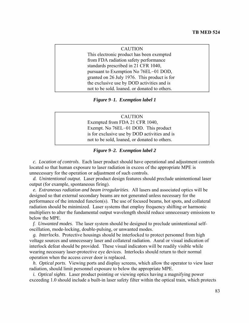
TB MED 524
83
e of focused beams, hot spots, and collateral
r
. Laser product pointing or viewing optics having a magnifying power exceeding 1.0 should include a built-in laser safety filter within the optical train, which protects
Figure 9–1. Exemption label 1
Figure 9–2. Exemption label 2 c. Location of controls. Each laser product should have operational and adjustment controls located so that human exposure to laser radiation in excess of the appropriate MPE is unnecessary for the operation or adjustment of such controls. Unintentional output. Laser product design featured. s should preclude unintentional laser output (for example, spontaneous firing). e. Extraneous radiation and beam irregularities. All lasers and associated optics will be designed so that external secondary beams are not generated unless necessary for the performance of the intended function(s). The usra ation should be mdi inimized. Laser systems that employ frequency shifting or harmonic multipliers to alter the fundamental output wavelength should reduce unnecessary emissions to below the MPE. f. Unwanted modes. The laser system should be designed to preclude unintentional self-oscillation, mode-locking, double-pulsing, or unwanted modes. g. Interlocks. Protective housings should be interlocked to protect personnel from high voltage sources and unnecessary laser and collateral radiation. Aural or visual indication of interlock defeat should be provided. These visual indicators will be readily visible while wearing necessary laser-protective eye devices. Interlocks should return to their normal operation when the access cover door is replaced. h. Optical ports. Viewing ports and display screens, which allow the operator to view laseradiation, should limit personnel exposure to below the appropriate MPE. i. Optical sights
CAUTION
standards prescribed in 21 CFR 1040, pursuant to Exemption No 76EL–01 DOD, granted on 26 July 1976. This product is for
This electronic product has been exempted from FDA radiation safety performance
the exclusive use by DOD activities and is not to be sold, loaned, or donated to others.
CAUTION Exempted from FDA 21 CFR 1040, Exempt. No 76EL–01 DOD. This product is for exclusive use by DOD activities and is not to be sold, loaned, or donated to others.

TB MED 524
84
tly
cate
laser- s
re f
able 9–1 ensity values for magnifying optical sights
the operator from reflections from specular surfaces or exposures to similar lasers during Force-on-Force training. The built-in safety filter will keep transmitted laser radiation levels at or below the appropriate MPE for that particular laser system. Such filters should not significanimpair visibility and should be permanently attached or designed so that the optical train cannot be assembled without the filter. The laser system or individual sight shall be marked to indithe level and type of protection afforded in the viewing optics either by OD and wavelength or by the use of a filter-marking code. This filter-marking code shall consist of a single-letter-safety code on the first line and an individual filter code on the second line consisting of a twoletter design code, a five digit manufacturing code, and a five digit lot number. Minimum ODfor the single-letter-laser-safety codes for both magnifying and non-magnifying optics aprovided in tables 9–1 and 9–2, respectively. These codes may not fully describe the level olaser protection in the sight.
TMinimum optical d
Safety Category 694.3 nm 800 nm–950 nm 1050 nm–1065 nm A 5.0 5.0 5.0 B 5.0 2.0 5.0 C 5.0 1.0 5.0 D 5.0 0.3 5.0 E 4.0 2.0 5.0 F 3.0 2.0 5.0 G 2.0 2.0 5.0 H 1.0 1.0 5.0 I 0.4 1.5 4.5 J 0.3 1.0 3.0 K 0.7 2.0 5.0 L --- 0.3 5.0 M 2.0 2.0 2.0 N 1.0 1.0 1.0 O --- --- --- P 3.0 3.0 3.0
Note: The OD values given above are for the entire system. For example, a filter with 4.7 OD at 694.3 nm a 5.8 OD at 1064 nm with essentially no protection in the 800 nm–950 nm band would be Category Dused in conjunction with a sight with an intrinsic OD 0f 0.27 in the near IR (800 nm–950 nm) due to the intrinsic filtration of the sight.
when

TB MED 524
85
able 9–2 inimum optical density va
T
lues for non-magnifying optical sights MSafety Category 1050 nm–1065 nm 694.3 nm 800 nm–950 nm
A 3.5 3.5 3.5 B 3.5 3.5 0.5 C 3.5 3.5 --- D 3.5 3.5 --- E 3.5 2.5 0.5 F 3.5 1.5 0.5 G 0.5 0.5 3.5 H 3.5 --- --- I --- --- 3.0 J --- --- 1.5 K --- 0.5 3.5 L 3.5 --- --- M 0.5 0.5 0.5 N --- --- --- O --- --- --- P 1.5 1.5 1.5
Note: The OD values given above are for the entire system. j. Nonbeam hazards. Electronic systems should be designed according to MIL–HDBK–
formation
nd potential bystanders to preclude laser injury.
rning
ld
VISIBLE", as appropriate, should precede the word "RADIATION." The r the
l be displayed in the lower right
t ng colors
1
1454A. Other hazards associated with the laser and its operation should have engineering controls according to MIL–STD–882D. See chapter 8 of this bulletin for additional inon nonbeam hazards. k. Laser warning labels. Laser warning labels for exempted lasers should provide clear instructions to the operators, maintainers, aLegible labels should be permanently affixed or inscribed on laser housings and readily accessible for viewing when the product is fully assembled. There are two types of walabels required for exempt lasers⎯ (1) Hazard warning label. This label describes the potential hazard of the device and shoube affixed near the fire button. The label should include the type of laser, and the word "VISIBLE" or "INlabel should also contain an appropriate instructional safety statement or control message fooperator or bystander as applicable. The ANSI classification wilcorner of the warning label rather than the FDA class (for example, "ANSI Class 2 Laser Product"). Numerical output information, such as wavelength(s) and maximum power outpu(when unclassified) should be located along the lower edge in a smaller font. The followiexamples show the suggested ANSI warning label colors. Exempt lasers often use mutedfor the labels. (a) Class 1 label. Class 1 lasers should have a label that simply identifies the laser as a Classproduct. An example is shown in figure 9–3.
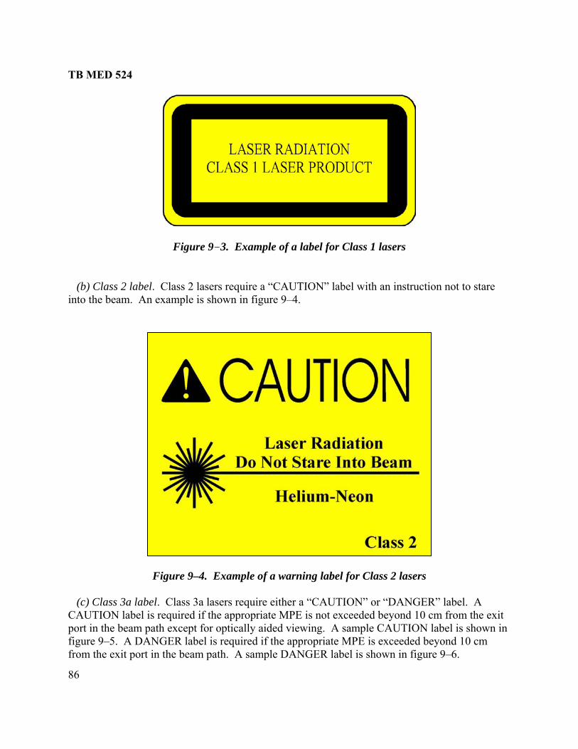
TB MED 524
86
e 9–3. Example of a label for Class 1 lasers
h an instruction not to stare into the beam. An example is shown in figure 9–4.
Figure 9–4. Example of a warning label for Class 2 lasers
(c) Class 3a label. Class 3a lasers require either a “CAUTION” or “DANGER” label. A CAUTION label is required if the appropriate MPE is not exceeded beyond 10 cm from the exit port in the beam path except for optically aided viewing. A sample CAUTION label is shown in figure 9–5. A DANGER label is required if the appropriate MPE is exceeded beyond 10 cm from the exit port in the beam path. A sample DANGER label is shown in figure 9–6.
Figur
(b) Class 2 label. Class 2 lasers require a “CAUTION” label wit

TB MED 524
87
Figure 9–5. Example of a warning label for Class 3a visible (400 nanometers to 700 nanometers) lasers
8. See paragraph 9–6 for more detailed formation on Class 3b and 4 requirements. Figure 9–9 depicts two typical warning labels used
in Europe.
Figure 9–6. Example of a warning label for Class 3a infrared (> 700 nanometers) and ultraviolet (< 400 nanometers) lasers
(d) Class 3b and 4 labels. Class 3b and Class 4 lasers require a "DANGER" label. A sample
ANGER label is given in figures 9–7 and 9–Din

TB MED 524
88
Figure 9–7. Example of a warning label for Class 3b lasers
Figure 9–8. Example of a warning label for Class 4 lasers
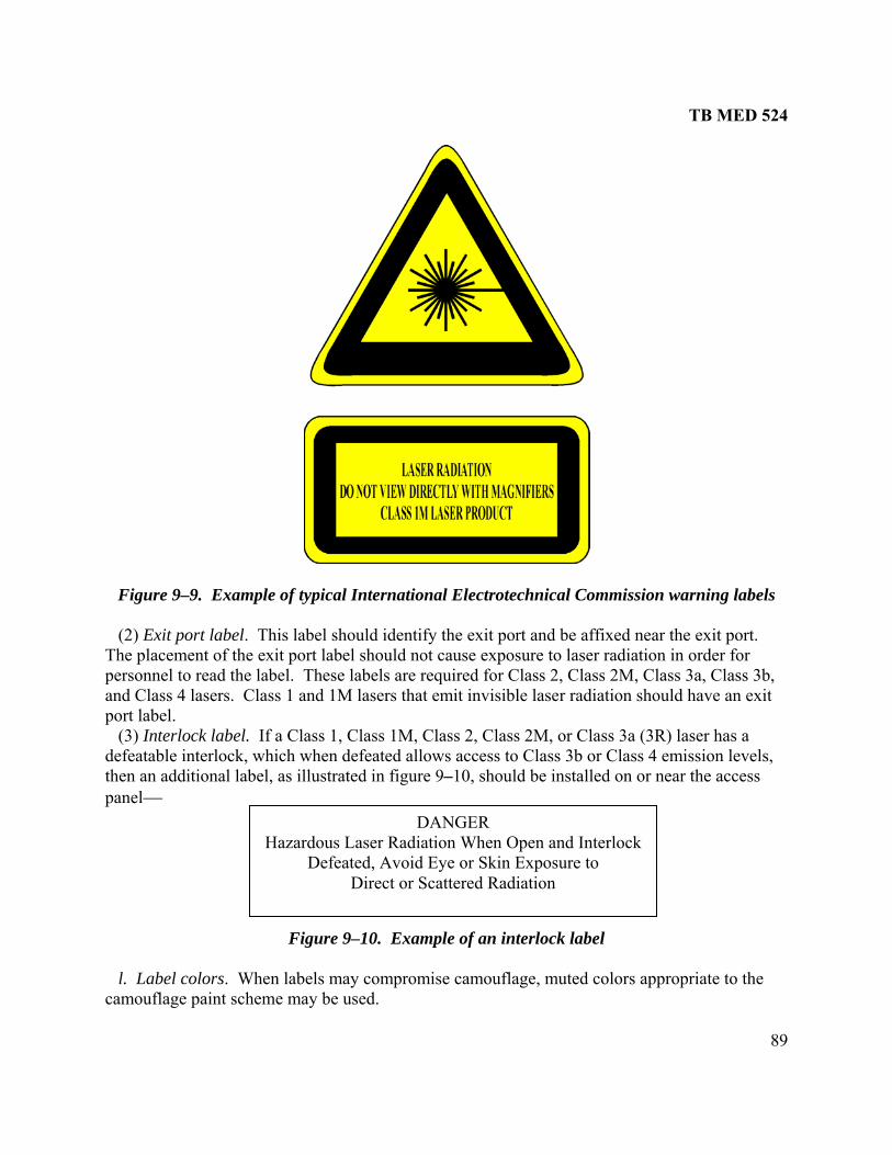
TB MED 524
89
Figure 9–9. Example of typical International Electrotechnical Commission warning labels
(2) Exit port label. This label should identify the exit port and be affixed near the exit port. The placement of the exit port label should not cause exposure to laser radiation in order for personnel to read the label. These labels are required for Class 2, Class 2M, Class 3a, Class 3b, and Class 4 lasers. Class 1 and 1M lasers that emit invisible laser radiation should have an exit port label. (3) Interlock label. If a Class 1, Class 1M, Class 2, Class 2M, or Class 3a (3R) laser has a defeatable interlock, which when defeated allows access to Class 3b or Class 4 emission levels, then an additional label, as illustrated in figure 9–10, should be installed on or near the access panel⎯
Figure 9–10. Example of an interlock label
to the
DANGER Hazardous Laser Radiation When Open and Interlock
Defeated, Avoid Eye or Skin Exposure to Direct or Scattered Radiation
l. Label colors. When labels may compromise camouflage, muted colors appropriatecamouflage paint scheme may be used.

TB MED 524
90
m. Classified. Information classified in the interest of national security will not be divulged on any label. n. Alternate labeling. Nonexempted lasers may incorporate military labeling when alternate labeling has been requested by the manufacturer and approved as a variance by FDA according to 21 CFR 1040. 9–6. Design requirements for Class 3b and Class 4 exempted lasers a. Warning labels. Class 3b and Class 4 lasers, as defined by ANSI, should be provided with a label similar to the examples illustrated in figures 9–7 and 9–8. The warning labels should contain warnings relevant to the specific situation. Labels may be intended for personnel operating lasers or others who may be exposed. For example, the operator warning for Class 3b and Class 4 ground target designators should read, “DO NOT AIM AT PERSONNEL OR FLAT GLASS SURFACES.” The bystander warning for visible and near-infrared (400 nm–1400 nm) Class 3b and Class 4 lasers should read “DO NOT LOOK INTO EXIT APERTURE.” Infrared (1400 nm–1 mm) and ultraviolet (200 nm–400 nm) Class 3b and Class 4 lasers that pose a skin hazard should have a label stating “DO NOT EXPOSE EYE OR SKIN TO DIRECT OR SPECULARLY REFLECTED BEAMS.” b. Danger labels. The "DANGER" labels should be printed on a white background with a bright red oval around the word "DANGER" and should contain a red "starburst" and black lettering. When warning labels compromise camouflage, muted colors (that is, olive drab) should be used. T um radiant power or energy should be added along the lower e ation is not classified in the interest of national security. c. Unintentional output. No single operator error or material failure should cause unintentional laser output that exceeds the MPE. At least two operator actions will be required to cause the laser to function. One of these should serve as a laser-arming control. Laser output should not be possible when this control is in the safe position. Power control switches may serve as laser-arming controls. Master key controls will be required only when specified by the procuring activity. d. Laser fire switch. The laser fire switch or trigger should be clearly identified and should be physically protected to prevent accidental activation. When possible, the switch should be a protected positive-action ("dead-man") type requiring continuous operator intent to operate the laser button. Laser activation circuitry should be of a fail-safe design so that continual depression or short-circuiting of the fire control switch will not cause repeated emissions. However, when operational considerations preclude the use of a dead-man switch, a toggled switch may be used, providing that adequate design safeguards are furnished to prevent long-term inadvertent lasing (for example, through “watchdog” timers and system logic switching). e. Exit-port cover. An exit-port cover should be provided, which is permanently installed within the laser product or attached to the device housing and which is capable of preventing access by any part of the body to all laser radiation in excess of the MPE. An example of such a device is a swivel-beam stop, which can be latched over the laser-output port, or a threaded attenuating cap wi is also acceptable. The c
he ANSI laser hazard classification, wavelength(s), and maximdge of the label if this inform
th chain. Rotation of the laser to an enclosed stowed positionover chosen should clearly indicate when it is in place.

TB MED 524
91
f. Remote control connector. A readily available remote control interlock capability should be incorporated on all Class 3b and Class 4 laser products (or alternatively on auxiliary power supply systems for laser products) that can be used during maintenance or service to interlock the system via an electrical cable to entrance door switches of a laser maintenance or service area. This requirement is not essential if the laser is always directed into an interlocked test set enclosure for maintenance or service procedures. When the terminals of the connector are not electrically joined, human access to all laser radiation and collateral radiation in excess of the MPE should be prevented. Once disconnected, the system should not automatically reactivate without an intentional reset. g. Boresight. Boresight alignment and retention should be designed consistent with system mission requirements and should be considered a safety-critical item. h. Emission indicator. Laser emission indicators should be provided to inform the laser operator when the laser is prepared to fire (armed) and when the laser is actually emitting optical radiation (firing). Indicators should be aural or visual (tone or light), or as specified by the procuring agency, and should not compromise camouflage. If visual indication is selected, the source should be visible under daylight as well as nighttime conditions. The source should also be visible when viewing through laser protective eyewear designed specifically for the wavelength(s) of the emitted laser radiation if such eyewear is required to be worn during operation, maintenance, or service. i. Visual indicators. Visual indicators should be located so that viewing does not require personnel exposure to laser radiation in excess of the MPE. A light could differentiate between "armed" and "firing" states by emitting either a continuous or blinking display. The display c continuous tone or light and an intermittent tone or blinking light, the continuous tone or light
, e, or service.
, an automatic disable capacity should be incorporated to inhibit laser firing if target acking outside the system specifications occurs or when the laser-sight line reaches the gimbal
limits or the system m apable of disabling e laser if no hardware stop e automatic features
during combat is permitted. l. Scanning beams. Laser products that use a beam
feature that terminates or reduces the beam output to the MPE immediately upon the cessation of scanning or upon scannin r scan velocity or mplitude. This requirement applies if such irregularities are not normal to the operation of the
ould be a part of the sight reticle or its outer ring. When armed and firing are differentiated by a
should mean "armed," and the intermittent tone or blinking light should mean “firing.” j. Airborne lasers. Laser systems installed on aircraft should be designed to prevent laser output while the aircraft is not airborne. However, a defeating switch (that is, protected from inadvertent activation) may be provided to override the ground interlock to aid ground operationmaintenanc k. Beam pointing. Laser product design features should incorporate controls to optimize positive operator control of beam pointing. This should include a means of ensuring boresight retention and the safety of software systems. For systems with automatic target tracking capabilitytr
ask limit. At least two independent systems should be cth s are installed. A provision to override thes
-scanning technique should include a
g pattern irregularities such as a change in eithealaser product, and also, if the unintended pattern changes would increase the hazard potential ofthe laser product.
TB MED 524
92
ce the hazardous emissions to the lowest level consistent with training
may be used to meet this requirement. When the laser can be used in both a ission and training mode, a visual indication should be provided to inform the operator and
ial tool should be
ark reticles should be considered so that the laser
ice que
prevent levels in excess of the MPE. Such an . Enclosed
m. Training mode. When a training mode for the laser is required by the contract, provisions will be made to redurequirements. This may be accomplished through the use of a beam attenuator, beam expander,or diffuser on the laser. Alternatively, separate systems such as less hazardous lasers and television camerasmoutside observers that the laser is positively in the training mode. A specrequired when switching from a training mode to a tactical mode when the tactical mode is Class 3b or Class 4. n. Determination of nominal ocular hazard distance. An estimated value of NOHD may be calculated using the appropriate laser system output parameters with regard to the environmental conditions under which the laser is to be used. While contractor determination of NOHD may be used during system design, the final NOHD must be certified by the government based upon a test (performed by the USACHPPM LORP) prior to government personnel exposure. o. Optical sights. Aiming optics should employ a reticle that can be viewed under any illumination condition for which the laser is designed. The reticle should not impair any dadaptation of the observer's eye. Calibratedoperator can determine the proximity of the laser beam to target buffer zones. 9–7. Laser test sets Design of laser test sets should ensure that laser radiation emitted during maintenance or servis no greater than the MPE. Such equipment should confine the laser radiation within an opaenclosure, which is adequately interlocked to enclosure should be provided with appropriate exterior warning indicators and labelsequipment can eliminate the need for specialized facilities as described in chapter 5 of this bulletin.

TB MED 524
93
CHAPTER 10
DESIGN REQUIREMENTS FOR ASSOCIATED SUPPORT EQUIPMENT
10–1. Introduction a. Support equipment includes test equipment, fixtures, and other enclosures procured to support laser systems. Support equipment should be designed to meet the following requirements based upon the hazard classification as defined by ANSI Z136.1 of the laser(s) to
n
,
the
be used with such equipment. b. The support equipment in conjunction with the laser system should meet the requirements of paragraph 9–5 and should be considered nonmilitary exempt under FDA Exemption #76 EL–01 DOD unless this equipment is used solely in support of exempted lasers. 10–2. General requirements a. Design goal. Design of associated support equipment should ensure that laser radiatioemitted during maintenance or service is no greater than the ANSI AEL for Class 1, and collateral radiation is not in excess of applicable limits when practicable. Such equipment should confine the laser radiation within an opaque enclosure, which is adequately interlocked toprevent levels in excess of the ANSI AEL for Class 1 when the enclosure is removed. Such an enclosure should be provided with appropriate exterior warning indicators and labels. Enclosed equipment can eliminate the need for specialized facilities. b. Nonbeam hazards. Other nonbeam hazards from the support equipment and the operationmaintenance, or service of the laser should be controlled by suitable engineering according toMIL–STD–882D. Adequate instruction as to safe techniques and personnel protective means should be included in all technical references (manuals) and plainly marked on the laser product when potentially hazardous areas are accessible. 10–3. Requirements for Class 1, Class 2, and Class 3a laser support equipment Support equipment, which is classified as Class 1, Class 2, or Class 3a, should meet the requirements of paragraph 9–5. 10–4. Requirements for Class 3b and Class 4 laser support equipment a. Test equipment. Laser system test equipment for boresight and laser-performance testing should enclose or attenuate the beam to limit personnel exposure to below the AEL for ANSIClass 1 and should be interlocked to the laser to prevent inadvertent laser operation outside enclosure if the test equipment is not used in a closed installation. b. Interlock switch. A safety (access) interlock switch should interface with ANSI Class 3b and Class 4 laser systems under test, such that inadvertent removal of test sets or poor connectionwill terminate or limit the laser output to the ANSI AEL for Class 1, or to the ANSI AEL for Class 2 if applicable.

TB MED 524
94
the
gned
at
-off switch should be provided, which allows emergency cut-off of laser output in
is
a
or carcinogenic mes when exposed to the laser(s) for which the beam stop has been designed. The beam stop
the type(s) and power level(s) for which it is procured. Firebrick, certain
on
c. Warning system. A warning system (for example, flashing light, audible indicator or other physical indicator external to the test set) will be activated immediately prior to operation oflaser and will remain activated until the laser output has been reduced to the ANSI AEL for Class 1 or to the ANSI AEL for Class 2, if applicable. The warning system should be desinot to attract personnel attention in such a manner as to create a potential hazard. d. Operation switch. All equipment used as support equipment for laser hardware, which could directly activate the laser, should incorporate a positive action ("dead-man") switch thmust be activated when laser firing is desired. When a dead-man switch is not incorporated, an emergency cutexcess of the ANSI AEL for Class 1 or Class 2 as appropriate. This switch should be readily accessible from the operator's position and should permit one-step operation. Normal power or control switches may fulfill this function (see MIL–STD–1425A). e. Master switch. A key-lock master switch should be required to prevent unauthorized activation of any test facility component used to supply power directly to the laser thatnecessary for its operation. f. Beam stops. The laser beam should be terminated by a beam stop, which is diffuse (nearlyLambertian surface), having a low value of reflectance at the laser wavelength(s). Where possible, such a beam stop should also be fire resistant and unable to emit toxicfushould be marked for ceramics, and graphite are examples of backstops for high-power infrared lasers. However, certain firebrick may contain beryllium compounds, which can produce hazardous beryllium fumes. Where toxic gases cannot be prevented, appropriate control measures for the protectiof personnel, such as appropriate exhaust ventilation, should be engineered into the system.

TB MED 524
95
CHAPTER 11
LASER SAFETY IN HEALTHCARE FACILITIES
11–1. Introduction a. This chapter provides guidance for the safe use of lasers and laser systems that are usedhealthcare facilities. It applies to those personnel associated with the installation, opemaintenance, and service of healthcare laser systems (HCLSs). An HCLS, as referred to by ANSI, is an apparatus which in
in ration,
cludes—
(4) Associated fluids and gases required for the operation of the laser. ecific class by a manufacturer according to the FLPPS (21 CFR
t ANSI
le or is lacking appropriate detail and
n
ptical systems to deliver laser energy to the atient. HCLSs, because of the short focal-length optical systems, have hazard distances of at
eams with the
operate with short open beam paths, as in laser hotocoagulation. Other delivery systems may use fiber optic cables to deliver laser energy
stems do not expose
sed lass 4 laser systems since most are designed to alter biological tissue. The
(1) A delivery system to direct the output of the laser. (2) A power supply with control and calibration functions. (3) Mechanical housing with interlocks. b. An HCLS certified for a sp1040.10 and 1040.11) fulfills all classification requirements of this document. c. Modified lasers should be reclassified according to this document or the most currenZ136.1. The FLPPS requires that the operating manuals for HCLSs contain adequate instructions for assembly, operation, and maintenance. These instructions should include clear warnings with precautionary statements to avoid possible exposure to hazardous levels of laser and/or collateral radiation. d. If information on operation and/or safety is not availabthe manufacturer and/or distributor cannot or will not provide the necessary information, the LSO/RSO should provide alternative safety instructions for the operation of the HCLS based oANSI Z136.3. The LSO/RSO may also provide additional information, training, and protocolsdepending on the policy of the organization responsible for the HCLS use. e. HCLSs, in general, have short focal-length opmost a few meters. As a contrast to HCLSs, tactical military lasers have collimated bminimal beam divergence and, therefore, hazard distances extend kilometers away from source. In addition, HCLSs maypthrough body cavities to the interior of the patient. In general, fiber optic syanyone, except the patient, during normal operation (that is, intact fiber). Fiber optic cables should be used with care to avoid cable breakage, which could expose personnel to hazardous laser energy. 11–2. Healthcare laser system–laser hazard classification a. General classification scheme. The classification scheme is based on the ability of the primary laser beam or reflected primary laser beam to cause eye or skin injury. Many lasers uin surgery are ANSI C

TB MED 524
96
PS
anufacturer U.S.
wave) at contribute to the laser’s medical use. The objective tissue
clude
inal
onto
e retina. Photosensitizing drugs are wavelength dependent and can affect the tissue’s usual interaction to lasers. c. Power and irradiance. The power and irradiance level of a laser system have a direct effect on the target tissue. The primary effect of the power and irradiance on biological tissue is thermal. For example, the energy from a carbon dioxide laser is strongly absorbed by water. Most biological cells consist of 80 percent or more water. When the carbon dioxide laser energy strikes tissue, the tissue absorbs the energy causing the cells to effectively boil. The boiling causes vaporization. It follows, the higher the power and/or irradiance, the more rapid the cellular vaporization. By controlling the irradiance and the spot size, the depth of vaporization and the width of vaporization can be controlled. d. Mode (CW/pulsed). The mode of HCLS plays an important role in its use. A laser that delivers high-powered pulses in a very short duration (photodisrupter) can cause tissue to ionize. The effect can be used to section transparent membranes and adhesions in the eye. A CW laser can be used to precisely cauterize and vaporize tissue with a continuous beam of energy. e. HCLS typical uses. Lasers for HCLSs are selected based on the specific laser/tissue interaction mechanisms. The aforementioned properties of the laser will dictate the mechanism and/or mechanisms that will most likely occur. The mechanisms typically involve photochemical (including photodissociative), photodisruptive, and thermal effects. Photochemical effects include photoablation (photodissociation) and photodynamic therapy.
HCLS laser hazard classification scheme information presented in this section is based entirely on laser radiation and does not include other nonbeam hazards. HCLSs manufactured or marketed in the United States for the U.S. Army must comply with all provisions of the FLPfor Light Emitting Products. b. U.S. Army classification scheme. HCLSs certified for a specific class by a maccording to the FLPPS may be considered as fulfilling all classification requirements of the Army. In cases where the HCLS classification is not provided or has potentially changed, the U.S. Army will classify the HCLS using the ANSI Z136.1 classification scheme. The USACHPPM LORP is responsible for classifying HCLSs when laser classification is not available. 11–3. Effects of medical lasers on the biological system a. General. Several properties of lasers contribute to their usefulness in the healthcare environment. The wavelength, power/irradiance, and mode (that is, pulsed or continuous are the three major factors thproperties of absorption, reflection, and transmission also play a significant role in determining a laser’s medical application. Additional factors that influence the laser/tissue interaction invariations in individual pigmentation, circulation, and thermal conductivity. b. Wavelength. Laser wavelengths interact with tissue differently, depending on the type of tissue, thereby, playing an important role in the hazard determination. For example, in the case of a laser directed at the human eye, a far-infrared laser will not generally be considered a rethazard, while a visible laser will be a retinal hazard. A carbon dioxide (far-infrared at 10,600 nm) laser will interact with the cornea, the first tissue in the beam path. Alternatively, a doubledNd:YAG (532 nm) laser will pass through the cornea and focus (~100,000 × magnification) th

TB MED 524
97
Thermal effects include coagulation or vaporization of tissue. Table 11–1 shows several lasers that may be found in a healthcare environment. The list is only general in nature and is representative a Table 11–1 Typical healthcare laser systems
nd not all-inclusive.
Laser Type Typical Medical Use Mode Wavelength Range
Wavelength(nm)
Excimer: Argon Floride
Pulsed UV-C1 193
Excimer: Krypton Flouride (KrF)
Pulsed UV-B2 248
Excimer: Xenon PulseChloride (XeCl)
d UV-A3 308
Helium Cadmium (He-Cd)
CW UV-A 325
Excimer: Xenon Pulsed UFlouride (XeF)
Photorefractive Keratectomy - (corneal surgery); tissue removal; Laser-Assisted InSitu Keratomileusis (LASIK) eye surgery.
V-A 351
Dye-Tunable Dermatology; blood vessel CW/Pulsed VISreduction; treatment of scars (keloids) and vascular lesions; photodynamic therapy.
typically 504, 577, 585, 590,
720, or 750
4 400-900:
Argon Dermatology; endoscopy; photocoagulation of the retina; plasti
CW VIS 488, 514
c surgery. Copper Vapor Dermatology; photodynamic
therapy. CW VIS 510, 578
Doubled Nd:YAG (KTP)
Dermatology; tattoo pigmentation breakup; blood vessel reduction; treatment of vascular lesions; endoscopy.
Pulsed VIS 532
Gold Vapor Photodynamic therapy. Pulsed VIS 628 Laser Diodes Gallium Arsenide (GaAs); Gallium Indium Arsenide (GaInAs)
Dermatology; other surgical applications.
CW/Pulsed VIS-NIR5 630-950
Helium Neon (He-Ne)
Used for aligning and aiming other lasers.
CW VIS 633
Ruby Pulsed VIS 694 Alexandrite
Dermatology; tattoo pigmentation breakup; blood vessel reduction; treatment of
Pulsed VIS 720 - 800
vascular lesions. Nd:YAG Dermatology; endoscopy; CW/Pulsed NIR6 1064 selective tissue
vaporization/coagulation; photodisruptor used in ophthalmology.
Erbium:YAG Tissue coagulation and Pulsed MIRvaporization; arthroscopy.
7 1540

TB MED 524
98
Table 11–1 Typical healthcare laser systems (continued)
Laser Type Typical Medical Use Mode Wavelength Range
Wavelength (nm)
Holmium:YAG Pulsed MIR 2140 Hydrogen Flouride (HF)
Pulsed MIR 2730
Erbium:YAG
Pulsed MIR 2940 Carbon Dioxide (CO2)
Many applications: dermatology; tissue vaporization; coagulation;
CW/Pulsed FIR
excision; incision; ophthalmology.
00 8 10,6
Notes: 1 UV–C – ultraviolet radiation (100 nm–280 nm) 2 UV–B – ultraviolet radiation (280 nm–315 nm) 3 UV–A – ultraviolet radiation (315 nm–400 nm) 4 VIS – visible 5 VIS–NIR – visible near-infrared 6 NIR–near-infrared 7 MIR–mid-infrared 8 FIR–far-infrared
11–4. Healthcare laser system–non-surgical lasers a. A variety of lasers, besides those with direct medical uses, are operated in healthcare environments. The most common non-surgical HCLS is the alignment laser. Alignment lasers are used to aim other HCLSs, such as a carbon dioxide cutting laser, or they are used to precisposition patient and equipment for nuclear magnetic resonance or positron emission tomography
ely
care environment, however, is a unique setting
trol atient
y require no user action. Due to the nature of HCLSs, administrative controls are almost always
measurements. b. Alignment lasers used in HCLSs are typically ANSI Class 1, Class 2, or Class 3a. Theolder style helium neon alignment lasers are usually Class 2; the newer diode alignment lasersare typically Class 3a. 11–5. Medical lasers–control and operation of healthcare laser systems a. Control of healthcare laser systems. Control measures for HCLSs are no different than control measures for lasers in general. The healthwhere hazardous lasers are used and patients are treated therapeutically with levels far above occupational exposure limits. Controls measures generally include engineering controls and administrative controls. The administrative controls include guidelines or SOPs, controlled areas, warning signs and labels, and laser protective devices. General explanations of conmeasures are explained in chapter 5. The presence of healthcare personnel, patients, and passociates influence the total hazard evaluation, and thus, the control measures implemented. Comments provided here apply only when the equipment is used as intended. Maintenance and special operation must be considered separately. b. Engineering controls. Engineering controls are the preferred method of control since the
TB MED 524
99
ty of nsidered in the analysis. In addition, the functionality and
otential failure of the engineering controls should be considered. For example, many HCLSs deliver the laser energy through a fiber optic cable. The possibility of the fiber breaking or cracking and delivering laser energy in an unintended direction may need to be considered when dete Z. AN nonbe ards thmay need to be considered when determining an NHZ. Chapter 8 lists several general nonbeam l uirements. Th ents are outlined below― of th ures. Requirements for lasers used by the U.S. A ed in A 11. A m plicati R 11–9 fo l ram is the explicit statement: "The design of y ety program will follow applicable guidelines in ANSI Z136.1 and ANSI Z136.3." ining. Training will be commensurate with responsibilities. rveillance. Identify laser workers acco append this docu t. The occupational health program on or activity generally is progr . O. The LSO/RSO is responsible for the progr nd implof controls. 1 ealthcare lase length lase otective e ar hazar a. The greatest incre ently has been in dermatology and plastic surgery. Potential ocular injuries are more likw ultiple la m surgery. This section tended tp ulti-wavelength hazards from lasers used for medical purposes, especially d logical surgery r treatment of vascular lesions. b. Current guidelines, SOPs, and policy doctrine may not sufficiently address or stress the importance of choosing and wearing only the correct laser protective eyewear, especially during m ngth laser admin d hea roviders should e priate lace an rigo ollowed ntifica edical purposes greatly increases when the specific treatment requires the use of more than one wavelength of laser energy, such as in tattoo removal. Typical laser protective eyewear is w ecific. A tector does not protect st all typesl or the case of reatment, several laser wavelengths may be used during o The haza otectiv ar does n otect agc elength bei e to operator fatigue and/or lack of situational awareness, the simple g to the appropriate laser-eye protector for the laser being used or ensuring the la offers m length p tion may not always be rigorously followed. As a result, re (2) Safety practices. he use of lasers for medical purposes should be reviewed. The guidelines should ensure that protocols and procedures address the problem of a appropri yewear is al osen for elected wa gth
necessary. When considering controls, the ability level of personnel to understand the controls (such as, written warning signs), the limits of the engineering controls, and the availabililaser protective devices should be cop
rmining the NH SI Z136.3 lists several am haz associated wi HCLSs that
aser hazards. c. Req e U.S. Army requirem
e Army policies and procedR 11–9 and DA Pam 40–
(1) Departmentrmy are outlin
aser safety progajor im
an Armon of A laser saf
r the
(2) Tra (3) Medical su rding to ix C of men
of the installati maintains tham a
amementation (4) LSO/RS laser safety
1–6. H r systems–multi-wavease in medical-laser use rec
r pr yewe ds
ely to occur to physicians (or nearby personnel) ser wavelengths to perforhile using m is in o inform
ersonnel on the mermato such as tattoo removal o
ulti-wavele procedures. Healthcare safety protocols are in ption. The potential for injury while using these lasers for m
is and are beingtrators lt p
rously fhcare
nsure that appro (1) Hazard ide
.
avelength sp n individual laser-eye pro a dermatolo
again of asers. F gical t
rd arises when the laser prng used for treatment. Dutask of switchin
ne session.urrent wav
e eyewe ot pr ainst the
ser protective eyewear tinal injuries have allegedly occurred.
r t
ulti-wave rotec
Safety guidelines fo
ssuming that ate laser protective e ways ch the s velen

TB MED 524
100
o asers should be clearly labeled as to their emitted wavelengths and type of laser. F velength is selected and in use. Laser prot shoul shoul te th anlaser protection that is afforded, as well as the OD for the protection. ( D is wa h dependent.) Current laser eye protective technologies o lti-wave protectioGenerally, however, a single laser eye protective device will not cover guidelines or SOP should address this issue where applicable. (See appendix D for sample g hazar h lasers m cause diffureflection hazards (thus, posing hazards for all ent of the procedures used and operating conditions present (including reflections from surgical in nts, apparatuses, and biohazard membranes) should be addressed.
f the laser. Lurther labeling should clearly indicate which wa
ective eyewear d be clearly marked and d indica e wavelength Note: O
d type of velengt
ffer mu length n. all wavelengths. The
uidelines.) dditional (3) A ds for medical lasers. Use of
personnel within the NHZ). Assessmigh-power ay se
strume

TB MED 524
101
CHAPTER 12
LASER SAFETY PROGRAM–LSO/RSO RESPONSIBILITIES
12–1. Introduction a. The LSO/RSO responsibilities are discussed with regard to laser systems. A complete
ver, a brief overview of description of LSO/RSO duties is beyond the scope of this chapter; howeLSO/RSO duties is provided below. For more detailed guidance, please consult the references listed in paragraph 12-1b(2). Any questions can be referred to the USACHPPM LORP at http://chppm-www.apgea.army.mil/laser/laser.html. b. Other high intensity optical sources (HIOS) can be hazardous (for example, Xenon arcs,
ntermeasure devices, and
entals. A good laser safety program will have the following key fundamental lements at all levels of the program⎯
h s
D–1425A, and 1
safety
er safety program
UV–A/UV–B phototherapy booths, UV germicidal hoods, infrared couUV lamps). Guidance on these HIOS can be found in the current: ACGIH—Threshold Limit Values; ANSI/Illuminating Engineering Society of North America (IESNA) RP-27.1-1996 ; and ANSI/IESNA RP–27.3-96. (1) Fundame (a) Knowledge about the general hazards and where to find needed information. (b) Assessment of the specific hazards. (c) Implementation of a level of protection from the known hazards. (2) Regulations and references. ANSI Z136.1 and ANSI Z136.3 provide guidance to establisa laser safety program. Currently, the requirements and policies outlining laser safety programfor the U.S. Army are given in AR 11–9, AR 385–63, DA Pam 40–11, MIL–STMIL–HDBK–828A. Product performance requirements for non-exempt lasers are given in 2CFR 1040. The references cover many aspects and environments including manufacturing and production, range safety, and medical operations. 12–2. General requirements a. Installation. Installations that operate Class 3b or Class 4 lasers should have a laser program. Management for each organization should assign an individual to serve as the LSO/RSO to be responsible for laser safety. The LSO/RSO requires this appointment from management to ensure users maintain safe practices with their equipment. Management may employ an LSO/RSO to oversee this responsibility while relying on technical input from an outside expert. The LSO/RSO may require special safety training, laser safety guidance documents, equipment, and support staff commensurate with the extent of his or her responsibilities. Each LSO/RSO, regardless of command level, should maintain a laser safety program with several key components. The key operational elements of a lasare given in Table 12–1.

TB MED 524
102
Table 12–1 Operational elements
Elements Description LSO Specifically appointed to the office and with specific authority and
duties.
Inventory An inventory of Class 3b or Class 4 lasers should be maintained and current.
Training A specific training program commensurate with potential hazards. Medical surveillance A medical surveillance program that identifies “at risk” personnel.
Documentation An overall program philosophy and procedures including guidelines, SOPs, regulations, and points of contact.
Survey schedule A periodic survey schedule should be implemented.
Program update A periodic update and review of the overall laser safety programshould be conducted.
b. LSO/RSO. The LSO/RSO is appointed in writing to set-up, manage, and enforce a laser safety program. The LSO/RSO training and experience requirements will be commensurate with the mission responsibilities and the overall installation or activity laser hazard level. The LSO/RSO determines and/or is responsible for the evaluation and control of laser hazards, including― (1) Laser classifications. (2) Hazard evaluations. (3) Procedure and equipment approvals. (4) Inventory, signs and labels. (5) Safety features. (6) Audits. (7) Training. (8) Medical surveillance. (9) Accident reporting. (10) Evaluation of laser treatment areas. (11) Administrative and engineering control measures. (12) Safety instructions. (13) Documentation. (14) Appropriate PPE, such as laser eye protective devices. c. Inventory. An inventory of lasers should be maintained LSO/RSO. The inventory should include, at a minimum, ANSI Class 3b and Class 4 and FDA Class IIIb and Class IV laser systems. The inventory is a cornerstone to the laser safety program. The inventory should be updated from both the user level and from the logistics level. If a laser is newly acquired, modified, or the operating conditions change, the inventory mechanism should have the ability to capture the new information from the user level. If a laser is purchased, decommissioned, or transferred, the inventory mechanism should capture the new information from the logistics level. The laser inventory should, at a minimum, contain: laser source type with the laser parameters specified, manufacturer, model number, quantity, hazard class, wavelength, power and/or energy, mode (that is, CW or pulsed), location of the laser (with pertinent information such as room number and phone number), the primary user and/or point of contact for the laser,

TB MED 524
103
and any additional notes such as safety , other laser parameters (that is, divergence) or pertinent special operation notes. An accurate and up-to-date inventory will aid significa d. Tra on and overall potential hazard level will dictate the need and degree of training for a training
quirement or periodic training program. The training area should include general laser safety n differ. Training can involve a required course
umentation distributed by the LSO/RSO to the user level. The LSO/RSO
nt utlined in appendix C of this document.
as program philosophies, policies, and procedures including training,
ary records required by applicable government and
should perform a periodic survey schedule, as SACHPPM LORP is
a. Laser locations. The LSO/RSO should know the locations of all laser equipment at his or examples are not all-inclusive and vary with organization:
y; d
m when
e
l the safe usage of laser equipment, which could pose potential hazards to personnel: engineering controls and administrative controls.
equipment required
ntly in the implementation of an effective laser safety program. ining. Training programs are a required part of a laser safety program. The missi
rewith the specific device because each situation caor involve simple docshould have the ability to determine the type and frequency of training requirements. (Note: The LSO/RSO should ensure medical maintenance personnel are trained and understand the hazards especially if they perform maintenance or service on the laser sources.) e. Medical surveillance. Medical surveillance should be implemented according to curreU.S. Army policy. The current U.S. Army policy is oTypically, the Occupational Health Office administers the medical surveillance program. The LSO/RSO should have a mechanism in place to identify laser workers and to monitor the medical surveillance program. f. Records and documentation. The laser safety program, in general, should be outlined in such written documentation laser use, guidelines or SOPs, regulations, maintenance, service, and points of contact. The LSO/RSO should ensure that the necessmilitary regulations be maintained. g. Survey schedule. The local LSO/RSOconsidered necessary, in all areas where laser equipment is used. The Uresponsible for the periodic surveys of Army installations (that is, reviewing installation laser safety programs and providing recommendations for improving these programs). h. Program update. The LSO/RSO should conduct a periodic update and review of the overalllaser safety program. 12–3. Operational procedures her installation. The following (1) On an Army installation, hazardous lasers can be found in such areas as laser laboratories, storage areas for weapons, and equipment that use lasers, maintenance shops, ranges, andmedical facilities. (2) For a healthcare environment, hazardous lasers can be found in such fields as oral surgerophthalmology; dermatology; dental; gastroenterology; pathology; gynecology; ear, nose, anthroat; and the operating room (generally, kept elsewhere and moved to the operating rooneeded). b. Hazard controls. The LSO/RSO should ensure that appropriate controls are in place. (Sechapter 5 and 6 of this bulletin or ANSI Z136.1 for more detailed information.) There are two general methods to contro

TB MED 524
104
ring controls are normally preferred, as they do not require an action from O should ensure these controls work and are appropriate and should
ensure the laser device itself is appropriately labeled. E gineering controls include beam enclosure, electrical do n
ation and placement (for example, at to laser areas with instru ts, dicate that the laser is in e
for laser equitrative controls requ
ent of the LSO/RSn and periodic rev or SOPs.
f safety guidelines (d) Wearing laser eye protective ded.
lain
the laser equipment, provide detailed control measures, and accidents or defective equipment. (Note: safety instructions
e normally useful but may not provide enough ines or SOP.)
(1) Engineepersonnel. The LSO/RS
xamples of entotal area, warning signs and/or lights
or interlocks intended to disable the laser upon entry to awith appropriate inform
entrance ctions concerning gaining entry to the area), and warning lighwhich in operation. Often different engineering and administrativcontrols are needed pment service or maintenance. (2) Adminis (a) Appointm
ire personnel action, such as the following: O.
(b) Preparatio iew of safety instructions, safety guidelines, (c) Posting o or SOPs near potentially harmful laser systems.
devices when nee (3) The LSO/RSO should ensure laser eye protective devices are in place and not defective. For laser eye protectors, this includes appropriate labeling of OD and wavelength. (4) The LSO/RSO should ensure the eye protectors are actually laser eye protectors. Guidelines or SOPs should be specific to the use and environment of the lasers and actuallyavailable to personnel that use the lasers. The safety guidelines or SOPs should clearly expthe potential hazards posed by
gprovide methods for reportinprovided by the laser system manufacturer ar
ty guidelinformation for completion of a safe
TB MED 524
105
APPENDIX A
REFERENCES
Section I Required Publications Except as noted below, Army regulation and DA pamphlets are available online from the U.S. Army Publishing Directorate (APD) website: http://www.apd.army.mil/. Field manuals are
: re
s, Military Handbooks, and
nt Printing Office website:
he Army Radiation Safety Program. (Cited in paras 1–4f, 1–4h, 3–5, 11–5c(1), 12–1b(2), and
available online from the APD (formerly the U.S. Army Publishing Agency (USAPA)) websitehttp://www.usapa.army.mil/. Technical bulletins, medical and USACHPPM technical guides aavailable online from the USACHPPM website: http://chppm-www-apgea.army.mil. DOD instructions are available online from the Washington Headquarters Services website: http://www.dtic.mil/whs/directives. Military StandardStandardization Agreements are available online at the Documentation Automation and Production Service (DAPS) website: http://assist.daps.dla.mil/. American National Standard Institute standards are available on line from the ANSI website: http://www.ansi.org/library/overview.aspx?menuid=11. Code of Federal Regulations are available online from the Governmehttp://www.gpoaccess.gov/CFR/index.html. AR 10–5 Organization and Functions. (Cited in para 1–4a.) AR 11–9 TE–1.) AR 40–10 Health Hazard Assessment Program in Support of the Army Materiel Acquisition Decision Process. (Cited in para 1–4d(3).) AR 40–400 Patient Administration. (Cited in para 3–5.) AR 385–10 Army Safety Program. (Cited in para 1–4g.) AR 385–40 Army Accident Reporting and Records. (Cited in para 3–5).

TB MED 524
106
d.
(Cited in para 1–4h.) MIL–HDBK–828A Laser Safety on Ranges and in Other Outdoor Areas. (Cited in paras 1–1d, 1–1e, 1–4h, 6–2a, 6–11k, 12–1b(2), C–5a, and H–2a.) MIL–STD–882D System Safety. (Cited in paras 9–1b, 9–5j, and 10–2b.) MIL–STD–1425A Safety Design Requirements for Military Lasers and Associated Support Equipment. (Cited in paras 9–1a, 9–2b(1), 9–4, 9–5j, 10–4d, and 12-1b(2).) 21 CFR 1010.2 Certification. (Cited in para 9–5b.) 21 CFR 1010.5 Exemptions for products intended for United States Government use. (Cited in para 4–1e.) 21 CFR 1040 Performance Standards for Light-Emitting Products. (Cited in paras 9–5, 9–5n, and 12–1b(2).)
AR 385–63 Range Safety. (Cited in paras 1–4f, 1–4g, 1–4h, and 12–1b(2).) DA Pam 40–11 Preventive Medicine. (Cited in paras 11–5c(1), and 12–1b(2).) DA Pam 40–501 Hearing Conservation Program. (Cited in para 8–12.) DA Pam 40–506 The Army Vision Conservation and Readiness Program. (Cited in para C–1b.) FM 8–50 Prevention and Medical Management of Laser Injuries. (Cited in para H–2a.) TB MED 523 Control of Hazards to Health from Microwave and Radio Frequency Radiation and Ultrasoun(Cited in para 8–6b.) JP 3–09.1 Joint Tactics, Techniques, and Procedures for Laser Designation Operations (http://www.dtic.mil/doctrine//jel/new_pubs/jp3_09_1.pdf).

TB MED 524
107
21 CFR 1040.10 Laser products. (Cited in para 11–1b.) 21 CFR 1040.11 Specific purpose laser products. (Cited in para 11–1b.)
9 CFR 1910.134 –5b(1)(b).)
of DOD Personnel from Exposure to Radiofrequency Radiation and Military Exempt
BK–454
rder 7400.2D for Handling Airspace Matters, Part 8 Miscellaneous Procedures, Chapter 34
No. 52 ption from the Food and Drug Administration
cts; Guidance for Industry and FDA. (Available . Department of Health and Human Services, Food and Drug Administration, Center
2.html
2Respiratory protection. (Cited in para 8 ANSI Z136.1–2000 Safe Use of Lasers. (Cited in paras 10–1a, 11–2b, C–4, and C–5a.) ANSI Z136.3–1996 Safe Use of Lasers in Health Care Facilities. (Cited in paras 11–1d, and C–4.) Section II Related Publications FM 100–14 Risk Management
ODI 6055.11 DProtectionLasers MIL–HDGeneral Guidelines for Electronic Equipment
AA OFProcedures Outdoor Laser/High Intensity Light Demonstrations (http://www.faa.gov) Laser NoticeGuidance on the Department of Defense ExemFDA) Performance Standard for Laser Produ(
from the U.Sfor Devices and Radiological Health (http://www.fda.gov/cdrh/comp/guidance/141 .)
Aerospace Areas; Air Traffic ervice Routes; and Reporting Points
14 CFR 71 Designation of Class A, Class B, Class C, Class D, and Class ES

TB MED 524
108
chapter J
Labor Standards
, ACGIH, incinnati, OH, 2005. (TLV is a registered trademark of the American Conference of
al Industrial Hygienists, Cincinnati, OH. Available at ACGIH, 1330 Kemper
200
NSI and Illuminating Engineering Society of North America (IESNA), RP–27.1–1996 ed Practice for Photobiological Safety for Lamps and Lamp Systems–General
NSI and IESNA, RP–27.3–1996 ce for Photobiological Safety for Lamps and Safety Systems–Risk Group
C 60825–1, edition 1.2 (2001-2008) ucts - Part 1: Equipment classification, requirements and user's guide
%Den.pdf)
2006)
Code
21 CFR SubRadiological Health 29 CFR 1910 Occupational Safety and Health Administration, Department of 29 CFR 1910.101Compressed gases (general requirements) ACGIH Threshold Limit Values (TLVs®) for Chemical Substances and Physical Agents
®CGovernmentMeadow Drive, Cincinnati, OH 45240-1634.) ANSI Z136.6–Safe Use of Lasers Outdoors ARecommendRequirements ARecommended PractiClassification and Labeling IESafety of laser prod(http://domino.iec.ch/preview/info_iec60825-1%7Bed1.2 IEC 60825–2 (2004-Safety of laser products - Part 2: Safety of optical fiber communication systems (OFCS) (http://www.iec-normen.de/previewpdf/info_iec60825-2%7Bed3.0%7Den.pdf) NFPA Code 30 Flammable and Combustible Liquids NFPA Code 70 National Electrical Code (Article 500 - Hazardous (Classified) Locations)
ttp://ww.nfpa.org/aboutthecodes/) (h
TB MED 524
109
5 ries Using Chemicals
ttp://www.nfpa.org/aboutthecodes/)
aser Radiation: Medical Surveillance and Evaluation of Over Exposure
valuation and Control of Laser Hazards on Military Ranges
inimum Requirements for Aircrew Protection Agai t the Hazards of Laser Target Designators
contains no entries.
orms s no entries.
NFPA Standard 4Standard on Fire Protection for Laborato(h STANAG–2900 ED.2(3) L STANAG–3606 ED.5 E STANAG–3828 ED.1(9)
nsM Section III
rescribed Forms PThis section
ection IV SReferenced fThis section contain

TB MED 524
110
This page intentionally blank

TB MED 524
111
APPENDIX B
RD EVALUATION AND CLASSIFICATION CALCULATIONS FOR HAZA
aser beam in almost all cases, azard evaluations based upon exposure limits for the eye can usually be applied to the rest of
dy by laser radiation depend highly on the wavelength or
ser radiation can cause photochemical effects on the body similar to sunburn. ared laser energy can cause thermal burns. The most hazardous wavelength
d the retinal hazard region (400 nm–1400 nm) where the injury otential is to the retina rather than other parts of the body.
–1 provides the definition of the mathematical symbols used
Table B–1
B–l. Introduction As the eye is the structure most sensitive to damage from the lhthe body. Effects on the bowavelengths of the laser. The wavelength of the laser could also be expressed in terms of
equency or energy per photon, but wavelength is the preferred unit to describe laser energy. frUltraviolet laMiddle- and far-infrregion for laser radiation is termep B–2. Definitions. Table Bthroughout appendix B.
Definitions of mathematical symbols Symbols Definitions
a Diameter of emergent laser beam (cm)
α Apparent angle subtended by a source at the location of the viewer (rad) αmax Apparent angle subtended by a source above which the thermal hazard is proportional to the
radiance of the source (100 mrad) αmin Apparent angle subtended by a source above which extended source MPEs apply (1.5 mrad) b Major axis of elliptical cross-section beam (cm) bo Diameter of laser beam incident on a focusing lens (cm) b1 Width of rectangular beam (cm) c Minor axis of elliptical cross-section beam (cm) c1 Height of rectangular beam (cm) CA Wavelength correction factor (700 nm < λ < 1050 nm) CB Wavelength correction factor (400 nm < λ < 600 nm) CC Wavelength correction factor (1150 nm < λ < 1400 nm) CE Extended source correction factor (table E–3) Cp Repetitive pulse correction factor (n-0.25) de Diameter of the pupil of the eye (varies from approximately 0.2 to 0.7 cm)

TB MED 524
112
Table B–1 Definitions of mathematical symbols (continuD Barrier separatio final focusing lens (cm)
ed) n distance from the focal point of the
DC Diameter of collecting aperture of optical system (cm) De Diameter of the exit pupil of an optical system (cm) Dexit Exit port diameter of a laser (cm) Df Limiting aperture from table E–5 (cm) DL Diameter of laser beam at range r (cm) Dm Diameter of measurement aperture from table E-6 used for classification (cm) Do Diameter of objective of an optical system (cm) Dρ Diameter of reflected laser beam at reflecting surface (cm) Ds Barrier separation distance (direct beam) (cm) DSD Diffuse reflection separation distance to barrier threshold limit (cm) Dw Diameter of a beam waist which could occur in front of the laser exit port (cm) e Base of natural logarithms, 2.718 f Effective focal length of eye (1.7 cm) f0 Focal length of lens (cm) F PRF (s-1 or Hz) Feff Effective (average) PRF (s-1) G Ratio of corneal irradiance or radiant exposure through magnifying optics to that received by
the unaided eye Geff Ratio of ocular hazard from optically aided viewing to unaided viewing γ Limiting field of view for MPEs based on photochemical hazards H, E Radiant exposure, (H) or irradiance (E) at range r, measured in J⋅cm-2 for pulsed lasers and
W⋅cm-2 for CW lasers Ho , Eo Emergent beam radiant exposure (H0) or irradiance (E0) at the minimum measurement
distance (10 cm) (units as for E, H) Hgroup Radiant exposure for the summation of all the energies in a group of pulses Hp The potential eye exposure, in the appropriate units, utilized in the determination of the
optical density of protective eyewear λ Wavelength of source (nm) Le Radiance of a source (W·cm-2·sr-1) Lp Integrated radiance of a source (J·cm-2 sr-1) µJ microJule MPE Maximum permissible exposure MPE:E MPE expressed as irradiance. For exposure to single pulses, the MPE is for peak power,
and for a group of pulses, the MPE is for the average power (W·cm-2) MPE:Hgroup MPE expressed as radiant exposure for the summation of all the energy in a group of pulses
(J·cm-2) MPE:H MPE expressed as radiant exposure for a single pulse or exposure (J·cm-2) MPEextended MPE for an extended source MPE:LP MPE expressed as integrated radiance (J·cm-2·sr-1)

TB MED 524
113
Table B–1 Definitions of mathematical symbols (continued) MPE:Le MPE expressed as radiance (W·cm-2·sr-1) MPE/Pulse MPE expressed as radiant exposure for each pulse in a pulse train (J·cm-2) MPEskin MPE for skin exposure MPEsmall MPE for a small source MPESP MPE expressed as radiant exposure for exposure to only one single pulse in a pulse train
-2(J·cm ) NA Numerical aperture of optical fiber nJ NanoJoule P Magnifying power of an optical system φ Emergent beam divergence measured in radians at the 1/e peak of irradiance points φ1 Emergent beam divergence of the major cross-sectional dimension of a rectangular or
elliptical beam, measured in radians (rad) φ2 Emergent beam divergence of the minor cross-sectional dimension of a rectangular or
elliptical beam, measured in radians (rad) Φ Radiant power (W) Φ0 Total radiant power output of a CW laser, or average radiant power of a repetitively pulsed
laser, measured in watts (W) Φd Radiant power transmitted by an aperture (W) Φeff Power transmitted by the measurement aperture (see table E–6 for apertures) Π Pi Q Radiant energy (J) Q0 Total radiant energy output of a pulsed in Joules (J) laser, measuredQd Radiant energy transmitted by an aperture (J) Qeff Energy transmitted by the measurement aperture from table E–6 (J) r Range from to the viewer to the laser (cm) r HZN Nominal hazard zone r HNO D
xceed the appropriate MPE (cm) The distance along the axis of the unobstructed beamirradiance or radiant exposure is not expected to e
from the laser beyond which the
ro Distance from exit port to a beam waist formed in front of the laser (cm) r1 Range from laser target to the viewer (cm) r1max ion to the MPE due to source size Maximum from laser that there could be a correctR Radius of curvature of a specular surface (cm) ρλ Spectral reflectance of a diffuse or a specular object at wavelength λ S Scan rate of a scanning laser (number of scans across the eye per second). t Duration of a single pulse or exposure (s) tmin Maximum duration for which the MPE (in J cm-2) is the same as for 1 ns T Total exposure duration (in seconds) of a train of pulses TL Barrier threshold limit
TB MED 524
114
Table B-1 Definitions of mat
x duration hematical symbols (continued)
Tma Total expected exposure duration; see limiting exposureθ Angle of incidence (equation 3) θs Maximum angular sweep of a scanning beam (rad) θν Viewing angle from the normal to a reflecting surface (figure B–5) ω0 Mode field diameter of single mode optical fiber (mm)
B–3. Viewing the g)
PE values listed h ncident on the body or rnea; however, in retina due to concentration of the ergy entering the s of the eye. The rst possible situa centrated
the retina in a dif
–4. Viewing the a. Specular reflec ion requires a mirror-like surface. If the reflecting rface is fairly larg aracteristics of the reflected beam may be considered
tical to those of at the range is the sum of the distances from the er source to refle
ing at th ace if the vature is known. generally
flect only a fractio dent upon the lar reflectivity
ce, typical p approximate l of
cident radiantazing angles, dep res
B 1 and B–2. The curves in figure B-1 show reflectance for light of polarization perpendicular ) to the plane of f polarization parallel () to the plane of incidence.
ch a curve drawn lection at normal incidence and a larizing angle at e of figure B–1 is shown in figure B–2 ere a collimated laser beam is incident upon a plate glass window.
primary beam (direct intrabeam viewinM ere are in terms of irradiance or radiant exposure ico many cases, the actual hazard is to the en eye and being focused on the retina by the cornea and lenwo
tion would exist if the eye was focused at infinity and the beam con
gths 400 nm–1400 nm). at
fraction-limited spot (wavelen
B reflected beam tion. Specular reflectsu e and flat, the chiden the direct beam except thlas ctor and from reflector to the eye. If the surface is not flat, the reflected
e cornea is less and menergy arrivcur
ay be calculated for a uniformly curved surf Discounting finely polished mirrors, reflecting surfaces will
re n of the beam. The magnitude of the reflection is depenspecu coefficient and the angle of incidence. For normal (perpendicular)
late glass will reflecincidenreflect
t approximately 8 percent and transparent plastics will ly 6 percent of the incident beam, but at near-grazing incidence, nearly al
the in energy is reflected. However, the beam tends to lose its collimation for gr
–ending on the size of the reflector. This effect is shown graphically in figu
(∟ incidence and for light oSu for water would show 2 percent refpo 53 degrees. The practical significancwh

TB MED 524
115
TB MED 524
115
Figure B–1. ving an index
Specular reflectance from both surfof refraction of 1.5
aces of plate glass ha
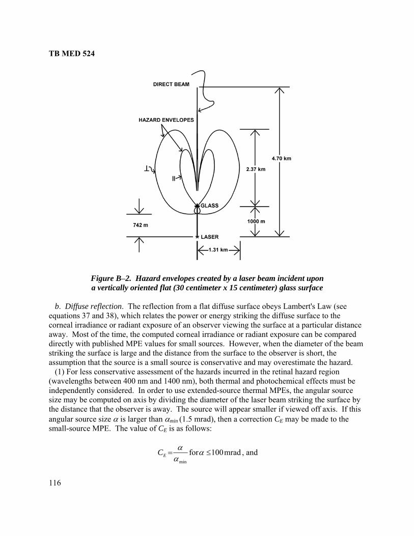
TB MED 524
116
Figure B–2. Hazard envelopes created by a laser beam incident upon a vertically oriented flat (30 centimeter x 15 centimeter) glass surface
b. Diffuse reflection. The reflection from a flat diffuse surface obeys Lambert's Law (see equations 37 and 38), which relates the power or energy striking the diffuse surface to the corneal irradiance or radiant exposure of an observer viewing the surface at a particular distance away. Most of the time, the computed corneal irradiance or radiant exposure can be compared directly with published MPE values for small sources. However, when the diameter of the beam striking the surface is large and the distance from the surface to the observer is short, the assumption that the source is a small source is conservative and may overestimate the hazard. (1) For less conservative assessment of the hazards incurred in the retinal hazard region (wavelengths between 400 nm and 1400 nm), both thermal and photochemical effects must be ndependently considered. In order to use extended-source thermal Mi
siPEs, the angular source
ze may be computed on axis by dividing the diameter of the laser beam striking the surface by the distance that the observer is away. The source will appear smaller if viewed off axis. If this angular source size α is larger than αmin (1.5 mrad), then a correction CE may be made to the small-source MPE. The value of CE is as follows:
mrad100formin
≤= ααα
EC , and

TB MED 524
117
mrad100formaxmin
2
>⋅
= ααα
αEC
Where αmax is 100 mrad. (2) For wavelengths between 400 nm and 600 nm, extended-source photochemical MPEs must also be considered, and either the thermal or photochemical MPE applies depending on which one indicates the most hazard. For exposure durations less than 10,000 s, the photochemical MPE is 100·CB J·cm-2·sr-1 (integrated radiance) averaged over a cone angle γ, which is 11 mrad for exposures less than 100 s. Exposures from 10,000 s to 30,000 s are not more restrictive. The source radiance or integrated radiance is computed by dividing the corneal irradiance or radiant exposure by the source solid angle. The source solid angle Ω is given by⎯
4
2πα=Ω ,
Where α is computed as described above. (3) For exposure durations from 100 s to 10,000 s, γ is 1.1× t mrad, and γ is 110 mrad for exposures up to 30,000 s. c. Reflections from natural objects. Although most targets encountered in a field situation are reasonably diffuse, some may behave as specular or semi-specular reflectors and shall be evaluated. Natural surfaces, which provide some form of specular reflections, generally have a smalllevels exist only near the could produce hazardous reflections at a distance. As a general rule, laser irradiances or radiant exposures that are safe to view as diffuse reflections will not create hazardous reflections from water droplets and natural foliage at viewing distances greater than 1 m from the reflector. Many glossy surfaces behave in a specular manner at grazing angles of incidence; however, the reflected beam will be very close to the beam axis of the initial beam. B–5. Other factors a. Atmospheric effects. With the exception of beams directed up through the atmosphere, the effect of atmospheric attenuation may become a major factor in evaluating the radiant exposure or irradiance at distances greater than a few kilometers. Atmospheric attenuation should not be included for beams directed up through the atmosphere into outer space. This attenuation is the sum of three effects: Mie (or large particle) scattering, where the particle size is greater than the wavelength of the optical radiation and is normally the greatest contributor in the visible and near-infrared; Rayleigh (or molecular) scattering, where particle size is much less than the wavelength, is reasonably constant for a given wavelength, and is the greatest contributor in the ultraviolet; and absorption by gas molecules, which is normally relatively insignificant in
radius of curvature (for example, water droplets, leaves) such that hazardous reflected reflector. Still ponds and flat-plate glass are the principal reflectors that
TB MED 524
118
comparison to scattering and may, therefore, be disregarded except in the infrared. Attenuation due to scattering is much more pronounced at shorter wavelengths; thus, red light from a ruby laser is scattered far less than wavelengths in the blue end of the visible spectrum. A clean atmosphere may, therefore, be expected to be relatively transparent to the ruby (694.3 nm) and Nd:YAG (1064 nm) wavelengths. The atmospheric attenuation effect upon a non-diverging beam is expressed by equations 21 and 22. The scattering effect may theoretically attenuate a ruby laser beam by as little as 10 percent at 10 km and 60 percent at 100 km, but such an atmospheric quality is rarely achieved even in arid zones. The meteorological visibility, based upon the entire visible spectrum, may not be readily utilized in arriving at the attenuation coefficient at a given wavelength. Atmospheric turbulence creates scintillation resulting in localized "hot spots" within the beam. Scintillation creates the largest variation in beam irradiances when the change of air temperature with height is great. The situation is most characteristic in a desert atmosphere with few clouds and least characteristic in a day with heavy overcast. A variation of local irradiances within a beam after traversing a beam path in excess of one kilometer may typically be a factor of 10 or more. Thus, local beam irradiances may occasionally exist, which are greater than would be expected if the beam experienced no turbulence. b. The effect of optical viewing instruments. (1) When viewing a bright object through a well-designed optical instrument, the amount of light or near-infrared radiation reaching the retina is increased by the square of the magnifying power of the system. For objects larger than a “point source,” there is a commensurate increase in the area of the retinal image; the retinal irradiance remains unchanged except for a slight reduction du (2) If, how reflection, the parallel rays of the laser beam would behave s if they were coming from a point source.
eased
ay
in paragraph B–6. Hazard classification and etermination of exposure limits may require the use of equations in Section II. Equations useful
in estimating exposure at significant distances from the laser apresented in Section III. Figures B–3 through B–5 illustrat r viewing conditions.
e to the loss or attenuation of light in the optical system. ever, the laser were viewed directly from within the beam or by specular
aThe retinal image, thus formed, may be diffraction-limited regardless of magnification by means of an optical viewing system. This means that the radiant power reaching the retina is incrby the square of the magnifying power of the optical system (except for light losses in the opticalsystem) and that there would be a commensurate increase in the retinal irradiance. (3) For some diode lasers, the size of the emitting source is large enough to qualify the laser as an extended-source laser. For these types of lasers, intrabeam viewing at close distances mresult in an image on the retina larger than would be created by a point source. An increase in the MPE may be permitted under these limited viewing conditions. B–6. Calculations for hazard evaluation and classification Calculations are not necessary for hazard evaluation and classification in many applications; however, in range applications and other specialized uses where eye exposure is contemplated, several types of calculations permit the important quantitative study of potential hazards. Mathematical symbols used throughout are definedd
nd optically aided viewing are e ocula

TB MED 524
119
m)
Figure B–4a. Intrabeam viewing–specularly reflected from flat surface (secondary beam)
Figure B–3. Intrabeam viewing–direct beam (primary bea
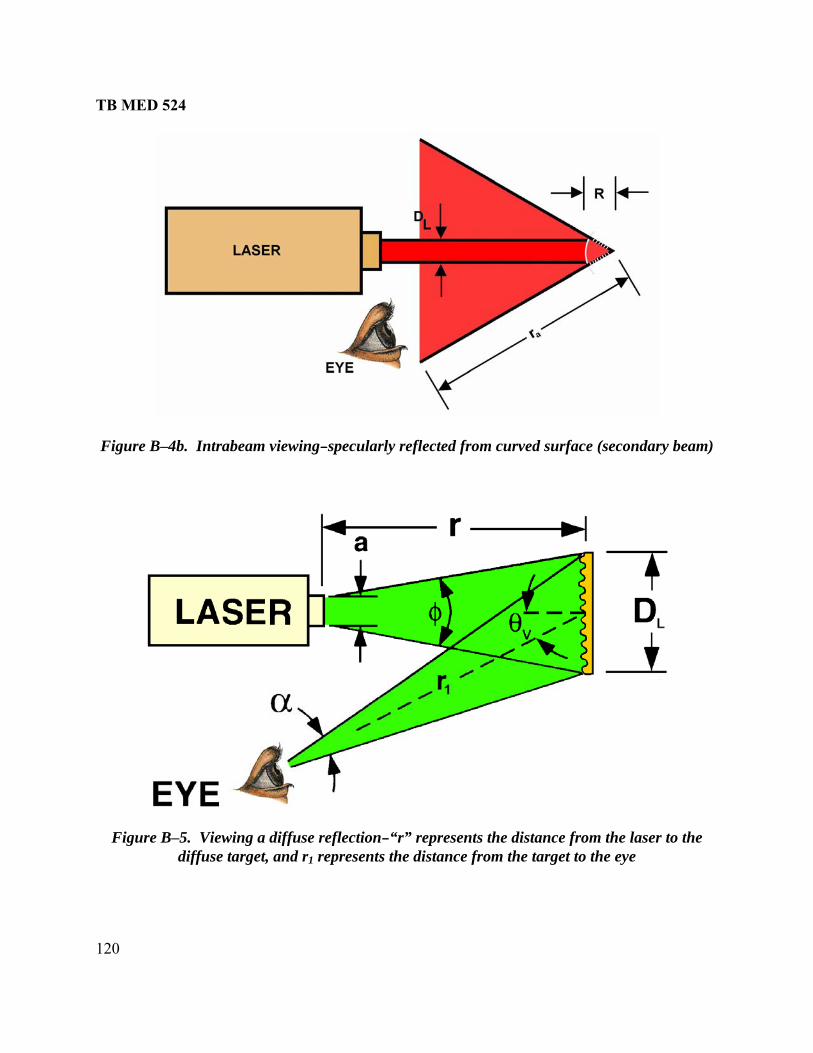
TB MED 524
120
reflected from curved surface (secondary beam)
Figure B–4b. Intrabeam viewing–specularly
Figure B–5. Viewing a diffuse reflection–“r” represents the distance from the laser to the diffuse target, and r1 represents the distance from the target to the eye
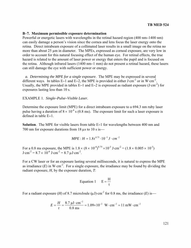
TB MED 524
121
B–7. Maximum permissible exposure determination Powerful or energetic lasers with wavelengths in the retinal hazard region (400 nm–1400 nm) can easily damage a person’s vision since the cornea and lens focus the laser energy onto the retina. Direct intrabeam exposure of a collimated laser results in a small image on the retina no more than about 25 µm in diameter. The MPEs, expressed as corneal exposure, are very low in order to account for this natural focusing effect of the human eye. For retinal effects, the true hazard is related to the amount of laser power or energy that enters the pupil and is focused on the retina. Although infrared lasers (1400 nm–1 mm) do not present a retinal hazard, these lasers can still damage the eye with sufficient power or energy. a. Determining the MPE for a single exposure. The MPE may be expressed in several different ways. In tables E–1 and E–2, the MPE is provided in either J·cm-2 or in W·cm-2. Usually, the MPE e (J·cm-2) for exposures lasting less than 10 s.
XAMPLE 1. Single–Pulse–Visible Laser. Determine the exposure limit (MPE) for a direct intrabeam exposure to a 694.3 nm ruby laser pulse having a duration of 8 × 10⁻⁴ s (0.8 ms). The exposure limit for such a laser exposure is defined in table E–1. Solution. The MPE for visible lasers from table E–1 for wavelengths between 400 nm and 700 nm for exposure durations from 18 μs to 10 s is⎯
For a 0.8 ms exposure, the MPE is 1.8 × (8 × 10-4)0.75 ×10⁻³ J·cm-2 = (1.8 × 0.005 × 10-3) J·cm-2 = 8.7 × 10⁻⁶ J·cm-2 = 8.7 μJ·cm-2. For a CW laser or for an exposure lasting several milliseconds, it is natural to express the MPE as irradiance (E) in W⋅cm-2. For a single exposure, the irradiance may be found by dividing the radiant exposure, H, by the exposure duration, T:
Equation 1
provided in tables E–1 and E–2 is expressed as radiant exposur
E
2375.0 108.1: −− ⋅⋅= cmJtHMPE
tHE =
For a radiant exposure (H) of 8.7 microJoule (μJ)·cm-2 for 0.8 ms, the irradiance (E) is⎯
2222
cmmW11cmW101.09ms0.8cmμJ8.7 −−−
−
⋅=⋅×=⋅
==tHE

TB MED 524
122
This is the peak irradiance since it represents the maximum irradiance that occurs during the pulse. Therefore, the MPE may be represented either as radiant exposure when it is provided in J·cm-2 or as irradiance when it is provided in W·cm-2. EXAMPLE 2. Single-Pulse, Near Infrared Laser. Determine the exposure limit for intrabeam direct viewing of a 1064 nm (Nd:YAG) laser having a pulse duration of 8 × 10⁻⁴ s. Solution. Since the direct beam exposure limit for this laser listed in table E–1 is five times that for the visible laser having the same exposure duration―
The MPE is 9 × (8 × 10-4)0.75 × 10⁻³ J·cm-2. (Note: CC - table E–3 is 1 for 1064 nm). Therefore, the MPE is 4.35 × 10⁻⁵ J·cm-2 = 43.5 μJ·cm-2.
b. Determining the MPE for a re titively pulsed laser. The MPE for a pulsed laser is omputed in the same way as for a CW laser. The exposure duration for the pulse is the pulse idth. However, for repetitively pulsed lasers, exposure to many pulses is possible over an
exposure duration of 10 or 100 s. The MPE is determined from three calculation methods (rules 1, 2, and 3). The MPE indicating the greatest hazard is the applicable MPE. The MPE for a single pulse during an exposure is limited to⎯ Rule 1: Single Pulse Limit. The MPESP for any single pulse during the exposure. Rule 2: Average Power Limit. The MPE for the duration of all pulse trains (within the exposure duration) lasting for T seconds, divided by the number of pulses, n, during T, for all pulse train durations up to Tmax (or T2 if T2 is smaller than Tmax). Rule 3: Repetitive Pulse Limit. The MPE for a single pulse within a pulse train multiplied by a correction factor CP, i.e., n-0.25, where n is the number of pulses that occur during an exposure duration Tmax. For this rule, the MPE is based on a minimum pulse width of tmin and all pulses within tmin (18 μs for λ = 400 nm to 1050 nm and 50 μs for λ = 1050 nm to 1400 nm) are considered one pulse. EXAMPLE 3. Repetitively Pulsed Visible Laser-Very High PRF. Dexposure T, Solution. Rule 2, average power limit will apply, since the PRF is greater than 55 kHz (1/tmin). However, all three rules will be tested.
2375.0 cmJ109 −− ⋅⋅= tCH C
pe
cw
etermine the direct intrabeam exposure limit of a 514.5 nm (argon) laser for a 0.25 s total operating at a PRF = 10 megahertz (MHz) and t = 10 ns (i.e., 10-8 s).
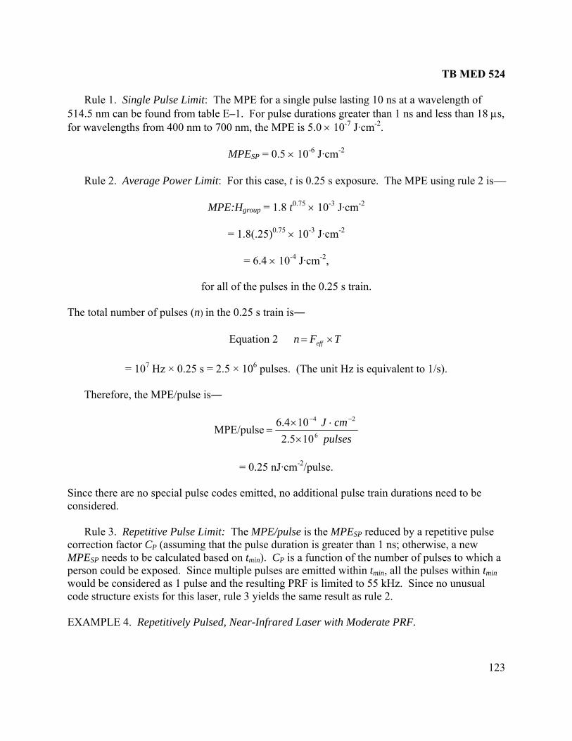
TB MED 524
123
lse lasting 10 ns at a wavelength of s,
-3 J·cm-2
lses in the 0.25 s train.
Rule 1. Single Pulse Limit: The MPE for a single pu514.5 nm can be found from table E–1. For pulse durations greater than 1 ns and less than 18 μfor wavelengths from 400 nm to 700 nm, the MPE is 5.0 × 10⁻⁷ J·cm-2.
MPESP = 0.5 × 10⁻⁶ J·cm-2
Rule 2. Average Power Limit: For this case, t is 0.25 s exposure. The MPE using rule 2 is⎯
MPE:Hgroup = 1.8 t0.75 × 10
= 1.8(.25)0.75 × 10⁻³ J·cm-2
= 6.4 × 10⁻⁴ J·cm-2,
for all of the pu The total number of pulses (n) in the 0.25 s train is―
Equation 2 TFn eff ×=
= 107 Hz × 0.25 s = 2.5 × 10⁶ pulses. (The unit Hz is equivalent to 1/s).
Therefore, the MPE/pulse is―
pulses6105.2 ×cmJ 24104.6
MPE/pulse⋅×
=−−
= 0.25 nJ·cm-2/pulse.
Rule 3. Repetitive Pulse Limit: The MPE/pulse is the MPESP reduced by a repetitive pulse correction factor CP (assuming that the pulse duration is greater than 1 ns; otherwise, a new MPESP needs to be calculated based on tmin). CP is a function of the number of pulses to which a
in tmin ual
ode structure exists for this laser, rule 3 yields the same result as rule 2. EXAMPLE 4. Repetitively Pulsed, Near-Infrared Laser with Moderate PRF.
Since there are no special pulse codes emitted, no additional pulse train durations need to be considered.
person could be exposed. Since multiple pulses are emitted within tmin, all the pulses withould be considered as 1 pulse and the resulting PRF is limited to 55 kHz. Since no unusw
c
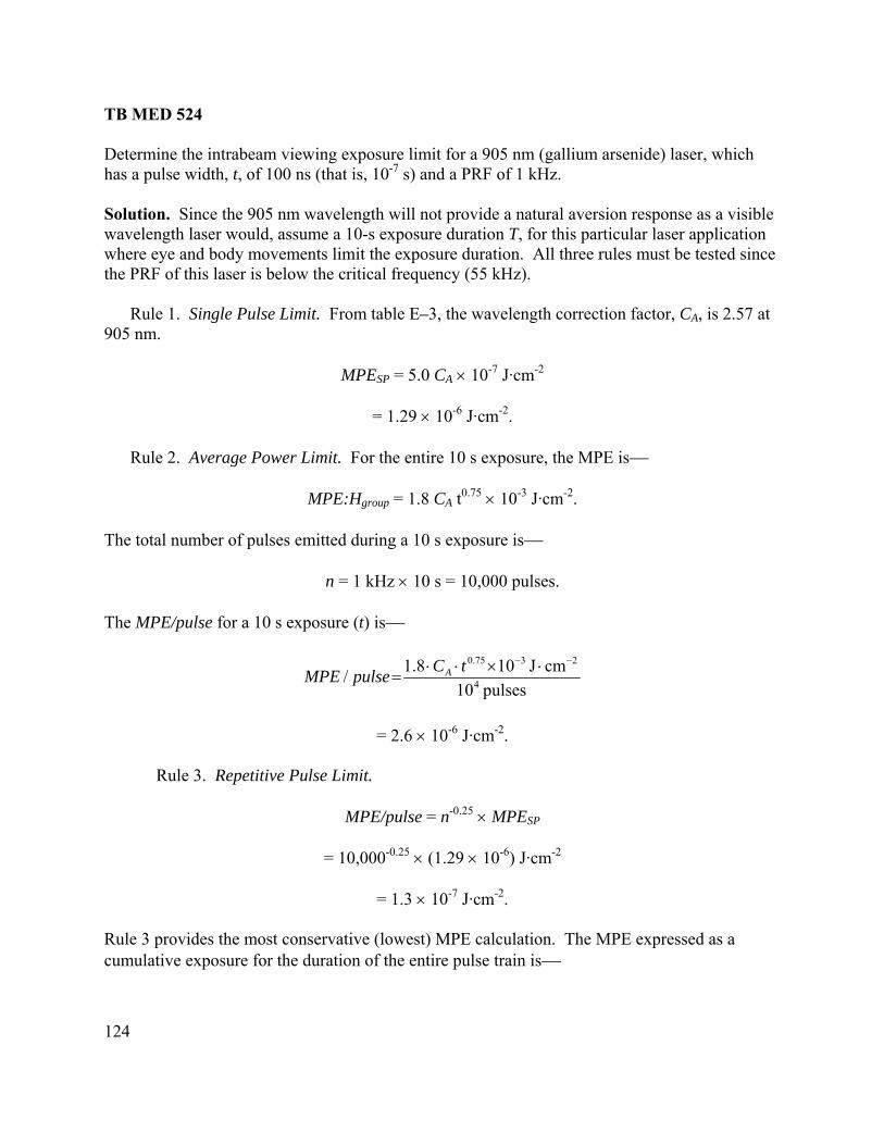
TB MED 524
124
olution. Since the 905 nm wavelength will not provide a natural aversion response as a visible ration T, for this particular laser application
here eye and body movements limit the exposure duration. All three rules must be tested since
Rule 1. Single Pulse Limit. From table E–3, the wavelength correction factor, CA, is 2.57 at
MPESP = 5.0 CA × 10 J·cm-2
= 1.29 × 10⁻⁶ J·cm-2.
he MPE/pulse for a 10 s exposure (t) is⎯
Determine the intrabeam viewing exposure limit for a 905 nm (gallium arsenide) laser, whichhas a pulse width, t, of 100 ns (that is, 10-7 s) and a PRF of 1 kHz. Swavelength laser would, assume a 10-s exposure duwthe PRF of this laser is below the critical frequency (55 kHz). 905 nm.
-7
Rule 2. Average Power Limit. For the entire 10 s exposure, the MPE is⎯
MPE:Hgroup = 1.8 CA t0.75 × 10-3 J·cm-2.
The total number of pulses emitted during a 10 s exposure is⎯
n = 1 kHz × 10 s = 10,000 pulses. T
pulses10/ 4=pulseMPE A
= 2.6 × 10
cmJ108.1 ⋅×⋅⋅ tC
= 10,000-0.25 × (1.29 × 10-6) J·cm-2
2375.0 −−
-6 J·cm-2. Rule 3. Repetitive Pulse Limit.
MPE/pulse = n-0.25 × MPESP
= 1.3 × 10⁻⁷ J·cm-2.
Rule 3 provides the most conservative (lowest) MPE calculation. The MPE expressed as a umulative exposure for the duration of the entire pulse train is⎯ c

TB MED 524
125
MPE:Hgroup = T × F × MPE/pulse
= (10 s)(103 Hz)(1.3 × 10⁻⁷ J·cm-2)
= 1.3 × 10⁻³ J·cm-2.
This MPE may also be expressed in terms of average irradiance.
s10cmJ101.3:
:3− ⋅×
=HMPE
EE group2−
=T
MP
-2
EXAMPLE 5. Low PRF, Long Pulse, Repetitively Pulsed Visible Laser.
etermine the exposure limit re Tmax = 0.25 s, pulse -3
olution. Since the PRF of the lase than 55 kHz, the pulse width exceeds 1 ns, the exposure duration is 0.25 s, and the pulses are evenly spaced, rule 3 is the appropriate method to
llow. All three rules will be tested.
Rule 1. Single Pulse Limit: The MPE for a single 1 ms pulse at the 632.8 nm wavelength o
MPESP = 1.8 t0.75 × 10-3 J·cm-2
= 1.8 × 0.0010. × 10-3 J·cm-2
J·
terms of average power for rule 1 is
-4= 1.3 × 10 W·cm .
D for a 632.8 nm (helium-neon) laser whewidth, t = 10 s, and F = 100 Hz. S r is much less
fo
fr m table E–1 is⎯
75
= 1.01 × 10⁻⁵ cm-2.
The MPE in ⎯
MPE:E = MPE/pulse × F
= 1.01 x 10⁻⁵ J·cm-2 x 100 Hz
= 1 x 10⁻³ W·cm-2 = 1 mW·cm-2.

TB MED 524
126
MPE:Hgroup = 1.8 t x 10 J·cm 2
Rule 2. Average-Power Rule. The MPE using rule 2 is—
0.75 -3 -
= 1.8 x (0.25)0.75 x 10⁻³ J·cm-2
= 6.4 x 10⁻⁴ J·cm-2
The MPE may be expressed in terms of average power
s0.25==
cmJ106.4::
24 −− ⋅×T
HMPEEMPE
he MPE/pulse for
le 2 is―
group
= 2.55 x 10⁻³ W.cm-2
The number of pulses in a 0.25 s exposure is n = F× T = 25 pulses. Therefore, tru
/pulsecmJ102.5625
5− ⋅×==ngroup cmJ106.4 2
24−
−− ⋅×H
Rule 3. Repetitive Pulse Lim
pulse is obtained by multiplying the MPESP by CP.
MPE/pulse = CP × MPESP J⋅cm-2
= (0.45)(1.01× 10⁻⁵) J·cm-2
= 4.55× 10- J cm- .
he most restrictive MPE/pulse is 4.55 μJ⋅cm-2 (rule 3) and should, therefore, be used. In terms of average power, this MPE is 0.4 EXAMPLE 6. One-Pulse Grou Find the exposure limit of a Q-switche 4 nm) that has an output of three, 0-ns pulses each separated by 100 ns.
qually spaced.
it.
CP = (n)-0.25 = (25)-0.25 = 0.45. The MPE/
6 ⋅ 2
T
5 mW⋅cm-2.
p, Short-Pulse Laser.
d Nd:YAG laser (1062 Solution. This is not a repetitively pulsed laser in the usual sense, that is, one having a ontinuous train of pulses lasting of the order of 0.25 s or more with the pulses being reasonably c
e
TB MED 524
127
Rule 1. Single-Pulse Limit. at the 1064 nm wavelength as found in table E-1 is—
MPESP = 5.0 C × 10 J⋅cm .
The correction factor Cc, found in table E-3, has a value of 1.0 at 1064 nm. Therefore, the MPE
MPESP = 5× 10 J⋅cm . Rule 2. Average-Power Rule. The average power MPE is calculated for a pulse train of duration, T, of 220 ns (total time for the 3 pulses plus the time between pulses), which is less than tmin of 50 μs.
-6 -2
The MPE for a single 20-ns pulse
-6 -2C
is⎯ -6 -2
MPE:Hgroup = 5× 10 J⋅cm for the 3 pulses
pulses3cmJ105/
26 −− ⋅×MPE =pulse
Rule 3. Repetitive Pulse Limit. Since the train duration, T, is less than t , all of the pulses
-6 J·cm-2 for the sum of the energies of all three pulses. Therefore, the MPE/pulse based on rule 3 is the same as rule 2 (1.67 μJ⋅cm-2). EXAMPLE 7. Series of Pulse Groups, Short-Pulse Laser. Find the exposure limit for a doubled Nd:YAG l ) used in a pulse-coded signal transmitter. The laser presents 100 wo age. Each word lasts 0.4 ms and ontains 10 laser pulses of 20-ns duration randomly spaced. The words are transmitted every
Solution. Rule 1. Single-Pulse Limit. T be found in table E–1.
Rule 2. Average-Power Rule. A number of calculations are required for this method since e pulses are in groups. First, consider one word, a group of 10 pulses that last 0.4 ms.
= 1.67 μJ⋅cm-2/pulse.
min
are considered as 1 pulse, and the energies are summed. Consequently, CP is 1.0. The MPE based on tmin is 5 × 10
aser (532 nmrds to transmit a mess
c1 ms for a total message length of 100 ms.
he MPESP for a 20 ns pulse can
MPESP = 5 × 10⁻⁷ J⋅cm-2. th

TB MED 524
128
= 0.4 ms)
J The MPE/pulse is then—
2375.0 cmJ108.1: −− ⋅×⋅= tHMPE group , (t
= 5.1 × 10⁻⁶ ⋅cm-2.
2726 J101 −− ⋅× cmJ101.5cm.5 −− ⋅×==
Second, calculate the MPE for the entire message length of 100 ms. The MPE for 100 ms from table E–1 is⎯
cmJ: −⋅MPE
he MPE is for all of the pulses contained within 100 ms. The number of pulses during this time is⎯
10/ pulseMPE
375.0 108.1 −×⋅= tH group2
24 cmJ102.3 −− ⋅×= T
pulses1000dpulses/wor10agewords/mess100 =×=n
The MPE/pulse
is then⎯
2724
cmJ102.31000
cmJ102.3 −×=×
=lse/ −−−
⋅puMPE
Since the second result is less than the previous, the for rule 2 is 3.2 × 10⁻⁷ J⋅cm-2.
Rule 3. Repetitive Pulse Limit. Th SP- ⋅cm-2 and CP is 1000-0.25 = 0.178.
o s.
sed in a pulse-code-modulated (PCM)
⋅
MPE/pulse
e MPE is 5 × 10 7 J Therefore, the MPE/pulse is 8.9 × 10⁻⁸ J⋅cm-2, which is the applicable MPE since it is the lowest.
XAMPLE 8. Repetitively Pulsed Pulse Gr upE
ind the exposure limit for an argon laser (514.5 nm) uFcommunications link. The laser presents 104 "words" per second (that is, 104 pulse groups per
20-ns pulses spaced at coded intervals such that each second) and each word consists of five ulse group lasts no longer than 1 μs. p
Solution. The effective PRF (Feff) of the transmitter is determined by multiplying the number of pulses per word by the number of words per second.

TB MED 524
129
kHz50words10pulses5 4 =×=F swordeff
Rule 1. Single-Pulse Limit. T be found in table E–1.
Rule 2. Average-Power Rule. A number of calculations are required for this method since e pulses are in groups. First, consider one word, a group of 5 pulses that last 1 μs.
he MPE/pulse is then⎯
he MPESP for a 20 ns pulse can
MPESP = 5 × 10⁻⁷ J·cm-2.
th
MPE:Hgroup = 5 × 10⁻⁷ J·cm-2. T
2727
cmJ101.05
c⋅ mJ105/ −−−−
⋅×=×
=pulseMPE
Second, calculate a 0.25 s exposure. The MPE for a 0.25 s (momentary exposure) from table E–1 is⎯
e number of pulses during this time
2375.0 cmJ108.1: −− ⋅×⋅= tHMPE group
24 cmJ1036.6 −− ⋅×= The MPE is for all of the pulses contained within 0.25 s. Ths⎯ i
pulses101.25 4×=×= TFn eff The MPE/pulse is then⎯
pulses1025.1cmJ1036.6/ 4
24
×⋅×
=−−
pulseMPE
28 −− cmJ1009.5 ⋅×=
ince the second result is less than the previous, the MPE/pulse for rule 2 is 5.09 × 10⁻⁸ J·cm-2.
isible sers) is⎯
S Rule 3. Repetitive Pulse Limit. The MPE for a single pulse based on tmin (18 μs for vla

TB MED 524
130
MPE:H = 5 × 10⁻⁷ J·cm-
All pulses occurring within tmin are con e. Pulse groups for this PCM ommunications link are 1 μs in durati n re pulse group occurs within tmin.
s contained within tmin is⎯
Words (tmin) = Group Frequency × tmin
2.
sidered a single pulson; therefore, an e tic
The number of pulse group
word18.0s1018s
o more than o
words000,10 6 =×= −
ne pulse group is contained within tmin. The number of pulses (words) separated y a time at least as long as tmin for a 0.25 s exposure duration is⎯
n(words) = 10,000 words/s × 0.25 s
= 2.5 × 10³
nCP
= 7.07 × 10⁻⁸ J·cm-2.
Since there are 5 pulses per word, the MPE/pulse is⎯
×
Nb
−− 141.0)105.2( 25.0325.0 =×==
27 cmJ105/ −− ⋅××= PCwordMPE
wordpulses /wordMPEpulseMPE // =
28 cmJ101.41pulses5
−− ⋅×==
28 cmJ107.07 −− ⋅×
ative MPE. The MPE/pulse for this example
l of 400 Hz and each pulse is 20 ns in length. Considering
Of the three rules, rule 3 provides the most conservs 1.4 × 10⁻⁸ J⋅cm-2. i
EXAMPLE 9. UV Laser, Dual Limits.
An argon fluoride excimer laser operating at 193 nm is used in the operating room for corneaculpting. The laser operates at a PRFs
all three rules, what is the lowest exposure limit for this laser, for a 10-s exposure duration?
TB MED 524
131
Solution. The MPEs for UV lasers (λ < 400 nm) are based on both thermal effects and photochemical effects. Therefore, dual limits must be considered when determining the most
strictive MPE for these types of lasers. The MPE, based on photochemical effects on the eye 1 ns to
0 ks. The thermal MPE for this wavelength, 0.56 t , also can’t be exceeded. The MPE can be computed by applying all three rules nd thermal effects.
e
0.25 cmmJ6.66J0.56 −− ⋅=⋅= tMPESP
it, the MPE is the same as for the entire exposure (3 mJ·cm-2) herefore, the MPE for rule 1 is based on the photochemical limit.
MPESP (Rule 1)= 3 mJ⋅cm-2.
Where t is now the total duration of the exposure, Tmax, which is 10 s.
0-s exposure, an individual could be exposed to 400 × 10 = 4000 pulses. The thermal MPE for each pulse is then⎯
reor skin, for 193 nm laser radiation is 3 milliJoule (mJ)⋅cm-2 for exposure durations lasting
0.253 for both photochemical a
Rule 1. Single-Pulse Limit. For this laser, the thermal MPE limit for exposure to a singl
pulse is⎯
0.2592 cmJ)10(200.56cm −− ⋅××=⋅ 22
For the photochemical limT
Rule 2. Average-Power Rule. For thermal effects, the MPE is⎯
225.0 cmJ56.0: −⋅⋅= tHMPEThermal group
22 cmJ1.0cmJ1.780.56 −− ⋅=⋅×=
In a 1
pulses104cmJ1.0
3
2
×⋅
=−
pulseMPEThermal
The MPE based on photochemical effects for an ulated exposure over a 10-s duration is 3 mJ·cm-2. Therefore the MPE/pulse based on photochemi ⎯
/pulsecmJ105.2 24 −− ⋅×=
accumcal effects is
cmJ100.3 23 ⋅× −−MPEcalPhotochemi
pulses104 3×pulse=
/pulsecmJ105.7 27 −− ⋅×=

TB MED 524
132
Since the photochemical MPE is les rule 2, the MPE for rule 2 is⎯
E according to rule 3, the repetitive-ulse correction factor is applied to the thermal MPE but not to the photochemical limit
because rule 3 protects agains al injury. The thermal MPESP is 6.66 mJ·cm-2. The exposure to 4000 pulses is possible. The value of CP, n-0.25, is 0.126. The MPE/pulse for rule 3 is⎯
cmJ0 −− ⋅
Comparing the MPEs, both the rules, the photochemical MPE for rule 2 yields the lowest MPE/pulse cm-2 or an average irradiance of 0.3 mW⋅cm-2. c. Determining the MPE for Extended Sources. Most lasers have a small source, α ≤ 1.5 mrad, but lasers that are formed by combining a laser diode with a collimating lens or by re-collimation of diffuse laser energy may have a larger source size when viewed at a close distance. For extended source lasers, the physical source size cannot exceed the diameter of the laser exit port aperture. The angular source size of these lasers is limited to no more than the
ivergence of the beam. Extended source MPEs are generally applied to diffuse reflections and ). When viewing diffuse reflections, the
ngle, αmin, is used to determine if the extended-source MPE applies. Figure B–5 shows the relationship between DL, a, and r1.
Equation 3
s than the thermal MPE for
27 cmJ015.7/ −− ⋅×=pulseMPE
Rule 3. Repetitive Pulse Limit. To compute the MPp SP
t sub-threshold pulse cumulative therm
23 14.8126.0cmJ1066.6/ −− ×=×⋅×=pulseMPE 24
rmal and photochemical for all three
of 0.75 μJ⋅
dthen only to the retinal hazard region (400 nm–1400 nma
1
cosr
DL υθα ⋅= , for θυ ≤ 0.37 radian
Equation 4 max1
mincos
rDL υθα ⋅
=
EXAMPLE 10. MPE for Extended Sources. Find the extended-source MPE for a gallium arsenide (904 nm), diode laser, used in a MILES
having a pulse width of 200 ns. The beam is circular, and its diameter at the exit port is 1.5 cm. The collimating lens (exit aperture) is 3 cm in
olution. Although most lasers have a small source, lasers created by a laser diode and collimating lens or by re-collimation of diffused laser energy can have a source size larger than
training laser, operating at 2.73 kHz and
diameter. The source size appears to be 4.5 mrad within a distance of about 6 m from the exit aperture. Find the MPE for this laser at a distance of 10 cm from the exit aperture. S
TB MED 524
133
e cannot αmin when viewed at a close distance. These lasers are extended sources. The source sizexceed the divergence of the beam. In addition, the physical source size cannot exceed the diameter of the laser exit aperture. The source size is a parameter only obtained through measurement. Beyond 667 cm, the source size is limited by the laser exit port, and a lower MPE applies.
mradcm
SizeSource 5.4667
== cm3
he small source MPE, calculated from rule 3, for this laser is⎯
CMPEpulseMPE
an exposure duration, Tmax, is ot specified. T2 is based on the source size and is contained in table E–3.
T
( ) 2cmJ/ −⋅×= PSPsmall
he number of pulses used to calculate CP is determined from T2 if T
n
( ) ( )
s10.10101010 0985.00015.00045.0
0985.00015.0
2 =×=×=−−α
T 73
The MPESP obtained from table E–1 is 1.28 × 10⁻⁶ J·cm-2. The number of pulses that the laser would emit in 10.73 s is 29,293 resulting in a CP alue of 0.076. The MPE is then⎯
.
The extended-source MPE for this laser is obtained from the angular source size and the small-
than 1.5 mrad. From table E–3, for sources smaller than 100 mrad, CE the ratio of the angular subtense to 1.5 mrad. At the evaluation distance of 10 cm, the source
subtends an angle of 4.5 mrad.
v
( ) 2826 cmJ1078.9cmJ1028.1/ −−−− ⋅×=×⋅×= Psmall CpulseMPE
source MPE. The small-source MPE is multiplied by the correction factor CE if the source subtends an angle greateris
.3mrad1.5
mrad4
min
===αα
EC
The extended-source MPE is⎯
( ) ( ) 7 J1094.2// − ⋅×=×= CpulseMPEpulseMPE 2cm−Esmallextended
d. Determining the MPE for a more complex repetitively pulsed las r. Laser systems continue to be more complex in nature combining several evaluation methods for one system. For instance a laser may be an extended source and emit pulse groups of both high and low frequency. Sometimes the pulses in these groups are counted singly and other times several
e

TB MED 524
134
n even more complicated scanning pattern so that the individual pulses are not the same intensity. Three rules have been given for evaluating repetitively pulsed lasers, either as a constant pattern or in pulse groups. However, exposure to groups of pulses of varying intensity
a aser into ave
fi sue I Z136. The human body is known to have two biological responses to optical
(1) Thermal and photochemical. Either effect can determine the MPE. For ocular exposure or skin exposure to ultraviolet, these limits are listed in table E–1 or table E–4 (the limits are
azards. For the retinal hazard region, the photochemical limit is 00 C J cm-2·steradian (sr)-2. For blue and green wavelengths, the photochemical MPE
it. In a m
ion of all energy received during these exposure durations. The retinal MPE is wri umption that the energy entering the cor used to a very o more than 25 μm in diameter. Continued exposure to the retina after a few seconds does not produce more damage to the retina from than from a 10-s exposure.
laser energy (usually diffuse reflections from sers with a large beam diameter) must be evaluated with different MPEs than direct corneal
tor is
htness of the urce) for larger sources (that is, larger than 100 mrad angular subtense).
pulses are combined into one big group for evaluation. Sometimes, these complex beams form a
is becoming more common, and extremely complicated pulse structures may develop before revision of this technical bulletin is issued. It is important to understand some principles of lexposure in order to formulate MPE limits for future systems where the parameters do not fitthe confines of this section. It is also important to note that the laser safety exposure limits hchanged very little since a comprehensive list of limits was first printed in 1973 in the rst isf ANSo
radiation—
essentially the same). However, there is a thermal limit listed on the right hand side of the tables, which must not be exceeded as well (0.56t0.25 J cm-2). (2) Retinal h1 Bproduces a lower exposure limit after a few seconds of exposure than the thermal lim
edical setting, where normal response functions to bright light have been disabled for a patient, the photochemical MPE limit should be reduced by a factor of 5. (3) Thermal hazards. Very short pulses produce a more pronounced effect than longer exposures. For pulses that are nanoseconds to microseconds long, there is a thermal confinementregion, where the retinal MPE remains constant (this value, (tmin) is 18 μs for wavelengths between 400 nm and 1050 nm and 50 μs for wavelengths between 1050 nm–1400 nm). The same MPE applies for the combinat
tten in terms of corneal exposure (J cm-2) with the assnea will be foc small spot on the retina, usually n
thermal effects
(4) Extended sources. Extended sources oflaexposure from collimated laser beams. Diffuse reflections of laser light more closely resembleexposure from other optical sources and, therefore, should not be penalized by directly applyingexposure limits for direct exposure to collimated laser energy. Therefore, a correction facprovided for intermediate size sources (currently between 1.5 mrad and 100 mrad angular subtense, but these values may change). The MPE is based on radiance (that is, brigso

TB MED 524
135
ch
ing the
lse, the MPE cannot be larger than it is for an equivalent CW laser, and that a reduction ctor should be applied for exposure to multiple pulses. However, for lasers with pulses of
varying intensity or for a laser that produces a raster scan on the retina with either a CW or pulsed laser, these rules are inadequate for determining an actual maximum permissible exposure limit.
ptable methods for determining correction factor for repeated exposures of visible or infrared energy to the retina. One is based
on the number of pulses received into the eye, and the other is based on the total “on” duration of the laser. The later can only be applied to retinal exposure accurately for pulses that are longer
(7) Varying-pulse-energy method. A combination of these two equivalent accepted methods can be used to determine the MPE to pulses that are shorter than tmin, but vary in energy and/or pulse width. First, the magnitude of the pulse with maximum energy output is determined.
d with a
sser (or same) pulse energy are assigned a width corresponding to the percentage of the energy of the maximum energy pulse multiplied by tmin. The combination of these widths is then used to determine an MPE from table E–1 for exposure durations from tmin to 10 s. This MPE will be
a. Based on the potential for a laser to exceed the MPE, the classification of a laser is dependent on whether the laser is likely to be used in conjunction with optically aided viewing instruments (that is, 7×50 mm binoculars) or strictly unaided viewing. A laser’s hazard classification is also based on the energy transmitted by the appropriate limiting aperture for
viewing. The limiting aperture (Df) can be 1 mm, 3.5 mm, mm, 11 mm, or somewhere in between. The following examples show techniques for
calculating parameters necessary for classifying a laser based on chapter 4 of this bulletin. The azard class of a laser depends on the effective output power or effective output energy of the
iting
(5) Exposure to multiple pulses. Exposure to multiple pulses of laser energy is generally more hazardous than exposure to a CW laser with the same average power. Determining how mumore hazardous can, at times, be difficult. Three rules have been established for determinrepetitive correction factor. These three rules are: the MPE cannot be larger than it is for a single pufa
(6) Exposure to pulses of varying intensity. There are two accea
than tmin. For these longer pulses, which are not often produced by modern military lasers, the two methods are equivalent.
Assuming that the duration of that pulse is less than tmin, then the duration of tmin is used for thewidth of that pulse. All other pulses occurring within an exposure duration of 10 s, anle
somewhat larger than it is for tmin. The energies of all the pulses are then combined and compared to the calculated MPE. This ratio between pulse energy and MPE can then be used todetermine optical density requirements or for determining NOHD. B–8. Laser classification
either unaided or optically aided7
hlaser and the corresponding AEL for each class. The effective output power or effective output energy per pulse is the power or energy transmitted by the proper measurement aperture listed in table E–6. Note that for unaided viewing, the measurement aperture is the same as the lim
TB MED 524
136
ses all not meet the AELs for the lesser classes.
ers e
stinguish lasers that are only azardous for optically aided viewing. Class 1 or Class 2 will be lasers that are not hazardous
t could be an be
XAMPLE 11. Q-Switched Doubled Nd:YAG Laser.
rod
aperture. The Class 1 AEL is obtained by multiplying the MPE for the laser by the area of the limiting aperture as specified in table E–5. b. The Class 2 AEL, for visible wavelength (400 nm–700 nm) lasers only, based on the MPE for 0.25 s viewing, is 1 mW. The Class 3 AEL, based on an acute hazard from the direct beam, is the lesser of 0.03⋅CA J in a single pulse or an average power of 0.5 W during a 0.25 s exposure (125 mJ). The Class 3 class has two subsets: Class 3a and Class 3b. The Class 3a AEL is defined as 5 times the Class 1 AEL for invisible wavelength lasers and 5 times the Class 2 AEL (5 mW) for visible wavelength lasers. All other Class 3 lasers are Class 3b. The Class 4 AEL, based on indirect hazards (such as, skin hazard and diffuse reflection hazard) encompaslasers that do c. A classification scheme has been introduced internationally and is likely to replace the current U.S. classification scheme in a few years. Under this classification, all Class 3a laswill be referred to as Class 3R (for reduced safety requirements), and two new classes will bintroduced: Class 1M and Class 2M. These classifications dihfor either viewing condition, and those that are not an unaided viewing hazard buoptically aided viewing hazard are either Class 1M or Class 2M. Class 2M will naturally restricted to visible (400 nm–700 nm) wavelengths, and neither Class 1M nor 2M lasers can exceed the Class 3b AEL even considering the potential use of optical viewing aids. E
Classify a single-pulse (<1 Hz) Q-switched doubled Nd:YAG laser (532 nm) having an output peak power specified by the manufacturer as 20 mW, a pulse duration of 25 ns, and a laser diameter of 5/8 inch. Solution. The output energy per pulse is⎯
( ) ( ) J0.5s102.5W102 87 =×××=⋅= −tΦQ
WhereΦ represents the peak power for this laser. The Class 3b limit for a single pulse is 0.03⋅CA J. From table E–3, CA is equal to 1.0 at the laser wavelength. Therefore, the Class 3b limit is 30 mJ. Since the output energy of this laser (0.5 J) is greater than the Class 3b limit, the laser is a Class 4 laser. EXAMPLE 12. Rhodamine 6G Dye Laser.
lassify a rhodamine 6G dye laser that has a peak output at a wavelength oCo
f 590 nm. The energy utput is 10 mJ in a 5 mm diameter beam for a duration 1 μs.
TB MED 524
137
f
EL
Solution. From table E–1, the MPE for a laser with a wavelength between 400 nm - 700 nm, having pulse duration between 1 ns – 18 µs, is 5 × 10⁻⁷ J·cm-2. The Class 1 AEL is the product othe MPE and the area of the limiting aperture defined in table E–5. The limiting aperture diameter for a 590 nm laser is 7 mm and the corresponding area is 0.385 cm2. The Class 1 Ais—
22
41 −⋅⎟
⎟⎞
⎜⎜⎛
×= cmJD
MPEAELClass fπ
⎠⎝
XAMPLE 13. Tunable Laser.
o ulse
. The output energies at ve the Class 1 or 3a AELs (see example 12). The Class 3b AEL
A at 750 nm. The laser’s 1 mJ and ystem.
= 5 × 10⁻⁷ J·cm-2 × 0.385 cm2 = 1.9 × 10⁻⁷ J.
The Class 3a AEL is 5 times the Class 1 AEL or 9.6 X 10⁻⁷ J, and the Class 3b AEL is 0.03⋅CA J. CA at 590 nm is 1, which results in a Class 3b AEL of 30 mJ. Since the laser output of 10 mJ is less than 30 mJ, it is a Class 3b laser. E Classify a tunable laser, which could emit between 0.7 µm–2 μm. The device has been altered toperate only at the 700 nm and 750 nm wavelengths. The radiant energy output in a single pis 1.0 mJ at 700 nm and 10 mJ at 750 nm. The laser is single pulsed with a pulse duration of 1.0μs and a 5-mm beam diameter. Solution. The MPE for a single 1-μs pulse at these wavelengths is―
27 cmJ105 −− ⋅⋅×= ASP CMPE
ith CA, from table E–3, equaling 1.0 for 700 nm and 1.26 for 750 nmw700 nm and 750 nm are abo
.03.C J/pulse) is 30 mJ at 700 nm and 38 mJ(010 mJ pulses are both below their respective Class 3b AEL making this laser a Class 3b s EXAMPLE 14. 1-Watt Argon Laser.
Classify a 1-watt argon laser, operating at 514.5 nm, used in a communications link. Solution. This laser could fall into one of several classifications depending on the radiant powerthat an individual could possibly be exposed to. The laser would be Class 1 if the entire beam path were enclosed, as in a sealed optical pipe. If, as an unenclosed beam, more than 0.5 W is emitted that would be collected by the proper measurement aperture (table E–6), the laser is a Class 4 system. Finally, if after passing through beam-forming optics the effective power in the beam is greater than 5 mW but less than 0.5 W, the laser is Class 3b.
TB MED 524
138
lassify a 632.8 nm visible laser (helium neon) used as a remote control switch. The laser is
22 cmW2.3or −− ⋅ .
n n
ns. ian or nearly top-hat beam profile, the
meter specified at 1/e points and the
EXAMPLE 15. 632.8 nm Visible Laser.
Celectronically pulsed with a 1-mW peak power output, a pulse duration of 0.1 s (hence an energyof 1 × 10⁻⁴ J/pulse), and a beam diameter of 1.0 cm. The recycle time of the laser is 5 s (maximum PRF = 0.2 Hz). Therefore, the laser may not be considered repetitively pulsed. Solution. Since the pulse duration for the laser is 0.1 s, the exposure duration is also 0.1 s. From table E–1, the MPE is⎯
tMPE 42375.0 cmJ102.3cmJ108.1 −−− ⋅×=⋅×⋅= powerpeak
The Class 1 AEL is the product of the MPE and the area of the 7-mm limiting aperture (0.385 cm2). Therefore, the Class 1 AEL is 1.23 mW for a single pulse making this helium neolaser Class 1. If multiple pulses are considered, rule 2 yields 1.18 mW for 2 pulses occurring i5.1 s, and for rule 3, n-0.25 is 0.84 for 2 pulses, reducing the Class 1 AEL to 1.03 mW and the laser is still Class 1. B–9. Central beam irradiance or radiant exposure for circular beams A laser’s irradiance or radiant exposure at the cornea is compared to the MPE (figure B–3). Often, the beam irradiance or radiant exposure is not provided in a laser’s specificatioHowever, if the laser is a single mode and has a Gausscentral beam values may be obtained from the beam diabeam radiant power or energy. The relationships are⎯
Equation 5 2227.14a
QaQHO ==
π;
Equation 6 2227.14aΦ
aΦEO ==
π
For safety evaluations, instead of the center beam values HO and EO, values of H and E averaged
sary. For retinal hazards, visible and near-frared lasers, the degree of hazard is dependent on the total energy reaching the retina. For this
over the correct limiting aperture (table E–5) are necesinspectral region a limiting aperture of 7 mm is used, representing the pupil size. Other limiting aperture sizes (Df) are used for wavelengths outside the retinal hazard region. A logical method for calculating E and H is—

TB MED 524
139
Equation 7 ( )[ ] ( )[ ]22 ,max27.1
,max4
ff DaDaE Φ
=Φ
=π
and
( )[ ] ( )[ ]22 ,max27.1
,max4
ff DaQ
DaQH ==
π Equation 8
Where max(a, Df) represents the larger of either the beam diameter (specified at 1/e points) or the limiting aperture size. EXAMPLE 16. A Single-P aser (532 nm).
e MPE. (Keep in mind that peak power is sometimes
isused and may actually indicate maximum average power.)
olution. The MPE for this laser (table E–1) is 5.0 × 10⁻⁷ J⋅cm-2. The output energy per pulse is
ulse (>1 Hz) Q-Switched Doubled Nd:YAG L
A single-pulse (<1 Hz) Q-switched doubled Nd:YAG laser (532 nm) has an output peak power specified by the manufacturer of 7 W, a pulse duration of 25 ns, and a 5-mm exit beam diameter.Determine whether the laser exceeds thm S1.75 × 10-7 J (see example 11). The diameter of the laser beam near the exit aperture is 5 mm, but in this region of the spectrum, Df is 7 mm. The radiant exposure of the laser is⎯
( )[ ]( )( )
272
7
2 cmJ1054.47.0,max fDa
1075.127.1 −−−
⋅×=×
==QH .
Since 4.54 × 10⁻⁷ J·cm-2 is less than 5.0 x 10⁻⁷ J·cm-2, the laser does not exceed the MPE.
am would not be considered a skin hazard.
ater than
27.1
EXAMPLE 17. 1-Argon Laser.
1-W argon laser operating at 514.5 nm is to be used in a communications link. Determine Aunder what conditions the emergent be Solution. The MPEs for skin exposure can be found in table E–4. For exposures gre0 s, the MPE is— 1
MPESKIN = 0.2 · CA W·cm-2.
CA for this wavelength is 1.0, so the MPE for skin is 0.2 W⋅cm-2. The limiting aperture (table E–5) for skin is 3.5 mm. Since the emergent beam power is 1 W, the size of the beam would have to be large enough such that irradiance of the laser was less than the 0.2 W·cm-2
PE. M

TB MED 524
140
Therefore,
24
aEMPE OSKIN π
Φ== .
Solving for a yields⎯
( ) cm2.52
cmW0.2π
W144
2
=⎟⎠⎞
⎜⎝⎛
=⋅
=MPEΦa
π.
er and beam divergence for circular beams he beam diameter used in safety analysis is the diameter at 1/e of peak irradiance. Therefore,
f the beam, would
1/e
The beam diameter at the exit aperture for this laser must be greater than 2.5 cm to prevent a possible skin hazard. B-10. Beam diametTan aperture that is the same size as the beam diameter, placed in the center ocollect 63 percent of the energy or power rather than the 87.5 percent or 100 percent that one would expect. Often the beam diameter or divergence is specified at 1/e2 points rather thanpoints so that equations 5 and 6 would calculate average values rather than the central beam values. In this case, the values of diameter or divergence are divided by the 2 to obtain thevalues. Calculate the emergent beam diameter (a) from a measured frac
1/e tion of total radiant
energy passing through an aper sian beam using the following equation:
Equation 9
ture for a Gaus
( )[ ]dfda−−
=1ln
2
Where d is the diameter of the aperture and f(d) represents the fraction of the beam energy
Equation 10
passing through the aperture. At a distance from the laser, the beam is no longer Gaussian but may be approximated by a Gaussian shape; therefore, the following relation may be used⎯
( )[ ]dfd− 2
DL −=
1ln.
For a Gaussian shape, the fraction of the total power or energy transmitted by a measurement aperture (Dm), may be determined from the following equations:

TB MED 524
141
2
10
⎟⎟⎠
⎞⎜⎜⎝
⎛−
−= L
m
DD
d efF
Equation 11 , or
Equation 12
2
10
⎟⎟⎠
⎞⎜⎜⎝
⎛−
−= L
m
DD
d eQQ .
vergence is to compare the beam diameter at a distance to the itial beam diameter.
XAMPLE 17. Calculation of Maximum and Central Beam Irradiance.
One way to calculate beam diin
E
From a Gaussian shaped beam, calculate the maximum central beam irradiance and the central beam irradiance averaged over a 7-mm aperture from a laser with a 5-mW output and an 8-mmbeam diameter. Solution.
a. Maximum beam irradiance. From equation 6⎯
( )( )2
3
cm0.8W1051.27 −×
=OE
= 9.9× 10⁻³ W·cm-2.
b. Maximum beam irradiance averaged over 7 mm. The fraction of the laser power that would ure from equation 11 is⎯ be transmitted by the 7-mm apert
535.012
8.07.0
=−=⎟⎠⎞
⎜⎝⎛−
efFd
0
perture is
ture is 0.385 cm2. The beam irradiance averaged over a 0.7-cm diameter The area of a 7-mm aper
⎯a
22 cmmW6.95
cm0.385⋅
0.535mW5 −×==E .
EXAMPLE 18. Laser Beam Diameter.

TB MED 524
142
ind the beam diameter to be used in calculations in hazard analysis. A laser beam diameter is specified as being 3 mm in diameter as measured at 1/e2 of peak-irradiance points. The beam is further specified to be single mode and Gaussian. Solution. Since the beam is Gaussian, we may use the relation that the beam diameter measured at 1/e2 points is greater by a factor of
F
2 = 1.41. The beam diameter for hazard analysis is fore, measured at 1/e. There
cm0.212cm0.3
==a
EXAMPLE 19. Gaussian Laser Beam.
ower of 5 mW and a measured power of 1 mW passing through a 7-mm
From a Gaussian shaped beam, find the approximate beam diameter of a Gaussian laser beamhaving a total output paperture. Solution. Using Equation 9, f(d) equals 0.2 (1mW/5mW)⎯
( )( ) cm1.5
2.01ln7.0 2
=−
−=a
EXAMPLE 20. Maximum Percentage of Total Power.
Find the maximum percentage of total power of a 3-mW helium-neon laser that will pass through a 7-mm aperture if the beam diam at 1/e2 points is 1.6 cm.
olution. The beam diameter used for safety calculations (1/e points) is 1.1 cm (see example
eter specified
S18). The power that passes through an aperture of diameter Df (equation 11) is given by—
=⎥⎥
⎦
⎤⎡ ⎟⎞
⎜⎛
− 2fD
⎢⎢
⎣−=
⎟⎠
⎜⎝10
LDd efF
mW1e132
cm1.1cm0.7
=⎥⎦⎢⎣
⎥⎤
⎢⎡−=
⎟⎟⎠
⎞⎜⎜⎝−
⎛

TB MED 524
143
B-11. Beam irradiance or radiant exposure for rectangular and elliptical beams The radiant exposure for either elliptical beam be calculated by making modifications to equations 7 and 8. For a rectangular beam⎯
Equation 14 ] ( )[ ]
a rectangular or can
([ ) ff cDF
max, 11 ⋅, and
Db
E,max
=
Equation 15 ( )[ ] ( )[ ]ff DcDbQH
,max,max ⋅= .
11
For an elliptical beam⎯
Equation 16 ( )[ ] ( )[ ]ff DcDbE
,max,max27.1⋅Φ
= , and
Equation 17 ] ( )[ ]([ ) ff DcDQH
,max27.1⋅
=
EXAMPLE 21. Beam Irradiance. Find the beam irradiance at 10 cm from an 860 nm diode-laser illuminator. The beam shape of the illuminator is rectangular with the following parameters: Φ = 2.5W, b1 = 2.5 cm, and c1 = 4 cm.
b,max
Solution. Using equation 14—
( )[ ] ( )[ ]ff DcDbE
,max,max 11 ⋅Φ
= =
( ) ( )2cmW25.0
cm4cm2.5W2.5 −⋅=⋅
=
. Radiant Exposure.
Find the radiant exposure of a 1064-nm laser designator emitting energy of 11 μJ/pulse with an elliptical beam shape, having dimensions of 2.5 mm × 12 cm.
safety evaluation is⎯
EXAMPLE 22
Solution. The radiant exposure used for

TB MED 524
144
( )[ ] ( )[ ]ff DcDbQH
,max,max27.1⋅
=
( ) ( )2cmμJ1.66μJ111.27
cm12cm0.7 ⋅−⋅=
×= .
s range he beam diameter of a Gaussian-shaped beam changes with range from the laser exit port. hen the beam waist occurs deep within the cavity of the laser, the best approximation of the
beam diameter with range is⎯
8
B-12. Beam diameter versuTW
φraDL += Equation 1 EXAMPLE 23. Diameter of a Gaussian Laser Beam. Find the diameter of a Gaussian laser beam at 1 km where the emergent beam waist occurs
ithin the law ser cavity, the diameter is 10 cm and the beam divergence is 0.1 mrad.
olution. S
( ) ( ) cm20radians10cm10cm10 45 =⋅+= −LD
If the beam waist for the laser occurs at or very n ar the exit port, the beam diameter change with
istance becomes more of a hyperbolic function than the linear one for the internal beam waist.
edSee figure B–6. The equation now becomes—
222 φraDL += Equation 19 EXAMPLE 24. Beam Waist at Exit Port. Solve Example 23 assuming a beam waist occurring very near the exit port. Solution.
( ) ( ) ( ) cm14radians10cm10cm10 24252 =⋅+= −LD
There are instances where the beam waist occurs a distance in front of the laser’s exit port (figure B–6). In this case, the beam diameter gets smaller from the exit port until the beam waist is reached and then begins to expand. For a Gaussian beam of this nature, the beam expansion quation becomes―
e

TB MED 524
145
( ) 222 φ⋅−+=Equation 20 0rrDD wL
is the beam diameter at the waist, r is the distance fromDr
w 0 the exit port to the beam waist, and is the distance from the exit port to the point where the beam diameter is DL.
eric attenuation eam irradiance (E) or radiant exposure (H) for a nondiverging beam at range, r, which is
Equation 21
Equation 22 The attenuation coefficient μ varies from 10-4 per cm in thick fog to 10-7 in air of very good visibility. The Rayleigh scattering coefficient at 694.3 nm is 4.8× 10⁻⁸ cm-1, and 1.8× 10⁻⁷ cm-1
even the cleanest atmospheres usually raises μ at 694.3 nm to at least 5× 10 cm .
he average irradiance for a circular beam at range, r, is the total power in the beam at that range t exposure in a non-turbulent
edium is the total energy in the beam at that range divided by the total area. The laser range
Figure B–6. Beam expansion with distance from the laser
B-13. AtmosphBattenuated by the atmosphere is⎯
reEE μ−⋅= 0
reHH μ−⋅= 0
at 500 nm. The effect of aerosols in -7 -1
B-14. Laser range equation Tdivided by the area of the beam at that range; likewise, the radianm
TB MED 524
146
equation, a formula for computing the irradiance or radiant exposure for a laser at any distance, is formed from the combinations of the equation for irradiance (equation 6) or radiant exposure (equation 5) with the appropriate equation for atmospheric attenuation (equations 21 and 22) and beam expansion (equation 19). The resultant range equations for circular beams are―
Equation 23 2222222
2
φφπ
rara +
⎥⎥⎦
⎤
⎢⎢⎣
⎡ +
27.1 μμ ee rr Φ=
Φ=
−−
and
Equati
E
2222222
27.1on 24
2π⎢⎢
φφ
μμ
raQe
ra
Qe rr
+=
⎥⎥⎦
⎤
⎣
⎡ +
−−
diant exposure at 1 km (105 cm) of a 0.25 J Q-switched Nd:YAG laser rangefinder. The laser has a beam divergence of 0.1 mrad (10 radian) and an emergent beam diameter of 0.7 cm. Assume an atmospheric attenuation factor of 1 × 10⁻⁷ cm-1.
H =
EXAMPLE 25. Radiant Exposure. Find the ra
-4
Solution. Since the laser output parameters are given in terms of energy, equation 24 is the appropriate formula to use.
( )( ) ( )( )
( ) ( )[ ]22cm0.7 + 45
cm10cm10
rad10cm10eJ0.251.27
517
−
−
×=
−−
H
( )( )( )( ) ( )[ ] 222 cm100.7
0.99J0.251.27+
=H
.
or lasers that form a waist downrange from the laser exit port, equations 23 and 24 are transformed by applying equation 20 for beam expansion component instead of equation 19 used
r non-focused beams. The location of the waist (r0) and the diameter of the beam at the waist for
23 cmJ1013.3 −− ⋅×=H
F
fo(Dw) are important measurements, although only a rough approximation of each is necessarylaser safety calculations. The laser range equations become⎯

TB MED 524
147
( ) 220
2
27.1φ
μ
⋅−+=
−
rrDΦe
w
r
and EEquation 25
Equation 26 ( ) 22
02
27.1 μ
=−QeH
r
. φ⋅−+ rrDw
EXAMPLE 26. Irradiance. Find the irradiance at 70 m from a low power CW tactical laser pointer (λ = 830 nm) with an output power of 1.5 mW, a beam diameter of 1.0 cm at the exit port, a beam waist located 5 m in front of the laser and measured to be 0.7 cm in diameter, and a beam divergence of 0.3 mrad. Assume an atmospheric attenuation factor of 1 × 10⁻⁷ cm-1. Solution. The irradiance at 70 m is⎯
( )( )( )( ) ( ) ( )[ ] 22322
3
cm100.35007000.71W1051.27
−
−
×−+
×=E
E= 1.48× 10⁻³ W·cm-2.
The MPE for this to this laser at 70 m would not be in danger. El
The equations expansion for these type beams must
ations for an elliptical beam are⎯
Equation 27 ]
laser is 1.82 × 10⁻³ W·cm-2. Therefore, an individual exposed liptical or rectangular beam radiant exposures can be calculated
much like that of a circular beam. for beambe substituted into the equation for circular beams. The values for b and c are not measuredclose to the beam waist if the waist occurs at some point behind the laser exit port. The radiant xposure (H) and irradiance (E) eque
[ ] [ 2φb + 1
27.1φ
μ
rcreE
r
+⋅Φ
=−
and
Equation 28 [ ] [ ]21
27.1φφ
μ
rcrbQeH
r
+⋅+=
−
.
For rectangular beams, the equations become⎯
Equation 29 [ ] [ ]2111
27.1φφ rcrb
eE+⋅+
= and
μrΦ −

TB MED 524
148
Equation 30 [ ] [ ]2111
27.1φφ
μ
rcrbQeH
r
+⋅+=
−
.
he expansion equation of a laser beam, in any two orthogonal axes, is different for many of T
these types of lasers. In many cases, the laser beam may come to a focus in front of the laser in one axis, while it is ing in the other. EXAMPLE 27. Gallium Arsenide Laser Illuminator. A gallium arsenide laser illuminator is used for training. Find the beam irradiance at 50 m for a laser with a rectangular beam and the following parameters:
b1 = 1.4 cm, c1 = 2.1 cm, φ1 = 55 mrad, φ2 = 21 mrad, Φ = 2.4 W Solution.
]
constantly diverg
[ ] [ 2111 φφ
μ
rcrbeE
r
+⋅+Φ
=−
( ) ( )( )
( )[ ] ([ )]cm3− 102150002.1cm105550001.4 3− ×⋅+××⋅+
=E eW2.4 cm5000cm10 17−⋅−−
25
24 cmW108.1cm102.96
W2.4 −− ⋅×=×
=E
EXAMPLE 28. One Dimension Beam Focus. Solve the previous example assuming that the beam is focused in one dimension. Use the same parameters with the following changes: φ2 = -1.2 mrad (focused beam), no external waist in b dimension, Dw (c dimension) = 0.7 cm, r0 (c dimension) = 5 m.
. Equation 29 needs to be modified since the beam focused in one dimension but not the other. Note⎯
Solution is
111 φrbDL +=
( ) cm276105550001.4 3
1 =××+= −LD
( ) 2
22
02
2 φ⋅−+= rrDD wL

TB MED 524
149
( ) ( ) ( )2322 105000.7 −×+=2 1.2cm500cm0 −−LD
cm5.452 =LD
)( )( 21 LL
r
DDeE
μ−Φ=
( )( )23 cmW101.6
cm5.45cm276−− ⋅×==E
B–15. Nominal ocular hazard distance
or unaided viewing conditions, solving equations 23 and 24 for
W2.4
r, and replacing H or E with the al to rNOHD (see figure B–7). This is a worst-case pheric attenuation coefficient was ignored.
Equation 31
Fcorrect MPE, will yield a value of r equstimate for the NOHD since the atmose
227.11 a
MPErNOHD −
Φ=φ
(for CW s)
Equation 32
laser
227.11 aQ−= (for pulsed lasers)
MPErNOHD φ
Solution. The MPE from table E μJ·cm-2.
EXAMPLE 29. rNOHD Find the rNOHD (ignoring atmospheric effects) for a 0.25-J, Q-switched, ruby laser rangefinderthat has a beam divergence of 1 mrad (10-3 radian), a pulse width of 25 ns and an emergent beamdiameter of 0.7 cm.
–1 is 0.5
( ) ( )273 7.0105
25.027.11011
−××
= −−NOHDr
km7.97=NOHDr .

TB MED 524
150
Figure B–7. Using the laser range equation to determine nominal ocular hazard distances
B-16. Viewing aided by an optical system The hazard of viewing a laser intrabeam is increased when optical viewing aids such as binoculars are used. The hazard may increase by as much as the square of the magnifying power of the optic. Standard 7×50 binoculars are used as the basis for laser hazard classification. Because these types of magnifying devices cannot focus at distances closer than 2 m, measurements for laser hazard classification are taken at this distance (2 m). The optical gain, G, is defined as the ratio of the irradiance or radiant exposure at the cornea when viewing is aided by an optical system, to that which is received by the unaided eye. The equation for optical gain
is⎯
Equation 33 22
20 PDG == .
De
D0 is the diameter of the entrance aperture of the optical system and De is the exit aperture diameter. This equation is also assuming 100 percent transmission of the laser light through the optics. P is the power of the optics system. EXAMPLE 30. Standard 7×50 Binocular. For a pair of standard 7×50 binoculars the optical power is 7, the entrance aperture is 5.0 cm, and the exit aperture diameter is slightly larger than 7 mm (the limiting aperture size for lasers in the retinal hazard region, 400 nm–1400 nm). Find the precise exit aperture diameter.

TB MED 524
151
Solution. Using equation 33 and solving for De yields⎯
2
20
PD
De =
cm714.075
2
2
==eD
The equation for optical gain is not completely realistic, in that it doesn’t consider transmission losses through the optical system. All optics transmits less than 100 percent of power or energy
on (τλ through optics, for the visible (400 nm–
rd r (P)
ultiplied by the limiting aperture (Df) and the entrance diameter of the optics (D0).
falling on them. The maximum transmissi700 nm) portion of the spectrum, is assume
) d to be 90 percent and at all other wavelengths
(302 nm–2800 nm) τλ is assumed to be no more than 70 percent. The collecting aperture (Dc) is often the same size as the measurement aperture (Dm) listed in table E–6 (5 cm for retinal hazaegion). The collecting aperture (Dr
mc) is, therefore, the minimum of the optical powe
( )0,min DDPD fc ×=
For beam diameters full effect of the optic d since the beam diameter at the exit ced to less than the lim refore, the ffective gain equation is⎯
less than Dc, the s will not be realize port will be redu iting aperture. The
e
( )Equation 34 2f
eff DG ×= λτ
In order to calculate
22 ,min Lc DD
the NOHD for a laser system when optics may be used to view the laser, ystem must be incorporated into equations
n DL, and will, therefore, make the equations difficult to solve. The equations for NOHD when optical aids are used (NOHD–M) are⎯
Equation 35
either purposefully or not, the effective gain of the s31 and 32. Note that for low-power systems, Geff at the location of the NOHD may still depend o
2)(
2. 711 aMPE
GΦr MNOHD −
⋅=φ
(for CW lasers)
Equation 36
eff
2)(
27.11 aMPE
GQr eff
MNOHD −⋅
=φ
(for pulsed lasers)
See Table B-2 for atmospherically corrected NOHD values.
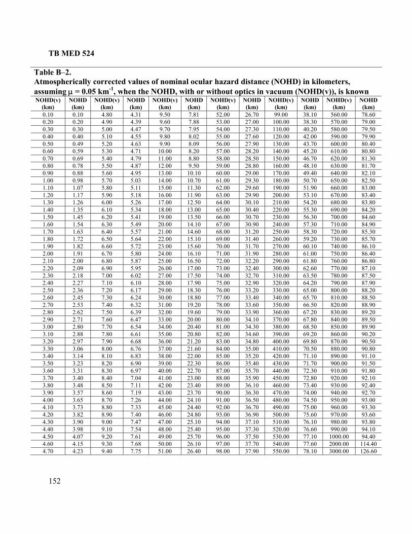
TB MED 524
152
Table B–2. Atmospherically corrected values of nominal ocular hazard distance (NOHD) in kilometers, assuming μ = 0.05 km-1, when the NOHD, with or without optics in vacuum (NOHD(v)), is known NOHD(v)
(km) NOHD (km)
NOHD(v) (km)
NOHD (km)
NOHD(v) (km)
NOHD (km)
NOHD(v) (km)
NOHD (km)
NOHD(v) (km)
NOHD (km)
NOHD(v) (km)
NOHD (km)
0.10 0.10 4.80 4.31 9.50 7.81 52.00 26.70 99.00 38.10 560.00 78.60 0.20 0.20 4.90 4.39 9.60 7.88 53.00 27.00 100.00 38.30 570.00 79.00 0.30 0.30 5.00 4.47 9.70 7.95 54.00 27.30 110.00 40.20 580.00 79.50 0.40 0.40 5.10 4.55 9.80 8.02 55.00 27.60 120.00 42.00 590.00 79.90 0.50 0.49 5.20 4.63 9.90 8.09 56.00 27.90 130.00 43.70 600.00 80.40 0.60 0.59 5.30 4.71 10.00 8.20 57.00 28.20 140.00 45.20 610.00 80.80 0.70 0.69 5.40 4.79 11.00 8.80 58.00 28.50 150.00 46.70 620.00 81.30 0.80 0.78 5.50 4.87 12.00 9.50 59.00 28.80 160.00 48.10 630.00 81.70 0.90 0.88 5.60 4.95 13.00 10.10 60.00 29.00 170.00 49.40 640.00 82.10 1.00 0.98 5.70 5.03 14.00 10.70 61.00 29.30 180.00 50.70 650.00 82.50 1.10 1.07 5.80 5.11 15.00 11.30 62.00 29.60 190.00 51.90 660.00 83.00 1.20 1.17 5.90 5.18 16.00 11.90 63.00 29.90 200.00 53.10 670.00 3.40 81.30 1.26 6.00 5.26 17.00 12.50 64.00 30.10 210.00 54.20 680.00 3.80 81.40 1.35 6.10 5.34 18.00 13.00 65.00 30.40 220.00 55.30 690.00 84.20 1.50 1.45 84.60 6.20 5.41 19.00 13.50 66.00 30.70 230.00 56.30 700.00 1.60 84.90 1.54 6.30 5.49 20.00 14.10 67.00 30.90 240.00 57.30 710.00 1.70 1.63 6.40 5.57 21.00 14.60 68.00 31.20 250.00 58.30 720.00 85.30 1. 0 69.00 31.40 260.00 59.20 730.00 85.70 80 1.72 6.50 5.64 22.00 15.11. 0.00 86.10 90 1.82 6.60 5.72 23.00 15.60 70.00 31.70 270.00 60.10 742.00 1.91 6.70 5.80 24.00 16.10 71.00 31.90 280.00 61.00 750.00 86.40 2. .80 10 2.00 6.80 5.87 25.00 16.50 72.00 32.20 290.00 61.80 760.00 862. 87.10 20 2.09 6.90 5.95 26.00 17.00 73.00 32.40 300.00 62.60 770.002. 87.50 30 2.18 7.00 6.02 27.00 17.50 74.00 32.70 310.00 63.50 780.002. .90 40 2.27 7.10 6.10 28.00 17.90 75.00 32.90 320.00 64.20 790.00 872. .20 50 2.36 7.20 6.17 29.00 18.30 76.00 33.20 330.00 65.00 800.00 882. 88.50 60 2.45 7.30 6.24 30.00 18.80 77.00 33.40 340.00 65.70 810.00 2. 8.90 70 2.53 7.40 6.32 31.00 19.20 78.00 33.60 350.00 66.50 820.00 82. 9.20 80 2.62 7.50 6.39 32.00 19.60 79.00 33.90 360.00 67.20 830.00 82.90 2.71 7.60 6.47 33.00 20.00 80.00 34.10 370.00 67.80 840.00 89.50 3.00 2.80 7.70 6.54 34.00 20.40 81.00 34.30 380.00 68.50 850.00 89.90 3.10 2.88 7.80 6.61 35.00 20.80 82.00 34.60 390.00 69.20 860.00 90.20 3.20 2.97 7.90 6.68 83.00 34.80 400.00 69.80 870.00 90.50 36.00 21.20 3.30 3.06 8.00 6.76 84.00 35.00 410.00 70.50 880.00 90.80 37.00 21.60 3.40 3.14 8.10 6.83 38.00 22.00 85.00 35.20 420.00 71.10 890.00 91.10 3.50 3.23 91.50 8.20 6.90 39.00 22.30 86.00 35.40 430.00 71.70 900.00 3. 0 91.80 60 3.31 8.30 6.97 40.00 22.70 87.00 35.70 440.00 72.30 910.03.70 3.40 8.40 7.04 41.00 23.00 88.00 35.90 450.00 72.80 920.00 92.10 3. 92.40 80 3.48 8.50 7.11 42.00 23.40 89.00 36.10 460.00 73.40 930.00 3. .70 90.00 36.30 470.00 74.00 940.00 92.70 90 3.57 8.60 7.19 43.00 234.00 3.65 91.00 36.50 480.00 74.50 950.00 93.00 8.70 7.26 44.00 24.10 4. .40 92.00 36.70 490.00 75.00 960.00 93.30 10 3.73 8.80 7.33 45.00 244.20 3.82 8.90 7.40 46.00 24.80 93.00 36.90 500.00 75.60 970.00 93.60 4. .80 30 3.90 9.00 7.47 47.00 25.10 94.00 37.10 510.00 76.10 980.00 934. .10 40 3.98 9.10 7.54 48.00 25.40 95.00 37.30 520.00 76.60 990.00 944.50 4.07 9.20 7.61 49.00 25.70 96.00 37.50 530.00 77.10 1000.00 94.40 4. 2000.00 114.40 60 4.15 9.30 7.68 50.00 26.10 97.00 37.70 540.00 77.604.70 4.23 3000.00 126.60 9.40 7.75 51.00 26.40 98.00 37.90 550.00 78.10

TB MED 524
153
Calculate the NOHD–M for example 29 (Q–switched, ruby rangefinder, 0.25 J per pulse, 1 mrad divergence, exit beam diameter of 7 mm) when the laser is viewed through 7×50 binoculars. Use table B–1 to correct the calculated result for atmospheric attenuation of 5 × 10⁻⁷ cm-1 (0.05 km-1).
Solution. The effective gain must be calculated for transmission of ruby laser light through 7×50 binoculars and then entered into equation 36. The MPE for a single pulsed (25 ns) ruby
ser is 5× 10⁻⁷ J·cm-2.
EXAMPLE 31. Calculate the NODH-M for Example 29.
la
( ) ( )[ ]( )
44cm4.9,cm5min0.9 2
22
=⎟⎟⎞
⎜⎜⎛
×=effG cm0.7 ⎠⎝
( ) ( )2273)( cm0.7
cmJ10544J0.251.27
1011
−⋅×⋅
×= −−−MNOHDr
km52.9)( =MNOHDr
When atmospheric attenuation is taken into account, r = 27 km.
pters 4 and 6) are caused by flat mirror-like surfaces. When a laser eam strikes a specular surface, the beam could remain collimated sending the laser power off in
a different direction (see figures B –4b). Laser targets cont ing flat glass surfaces (that is, windshields, view blocks) can direct laser energy back at th operator or into an ncontrolled area. The angle the beam makes with the reflecting surface determines where it is
A 0.05 J, Q-swit aser rangefinder is used in a tr nducted in a restricted laser ra t, located directly in is a high
obility multipurpose wheeled vehicle or high-mobility multipurpose wheeled vehicle downrange. The HMMWV has a flat glass windshield that could be
a potential hazard. The laser operates under the following para , φ = 2 mrad, PRF = 10 Hz, and pulse width = 25 ns. What is the potential radiant exposure from a specular
flection from the windshield at the operator’s location? Assume that the atmospheric
NOHD(M)
B-17. Hazards from specular reflections Specular reflections (see chab
–4a and B aine
ureflected and the percentage of the energy that is reflected. At normal incidence (beam perpendicular to surface), a flat glass surface will reflect about 8 percent (4 percent per surface)of the incident energy. At large, near grazing angles, most of the laser energy can be reflected. A flat mirror can reflect nearly 100 percent of the laser energy. EXAMPLE 32. Radiant Exposure.
ched, Nd:YAG, l aining scenario conge. The operator’s targe front of the laser,
m(HMMWV) located 2000 m
meters: a = 0.7 cm
re

TB MED 524
154
ion factor is 5× 10⁻⁷ cm-1. Would the laser operator be exposed to laser radiation in
ti e r E t h p s osu ince in d is ce o ss at nearly n l in ce t lase
lecti wou abo perc 4 pe fro t s of hie 4 percent m back surface). The all d ce th e be ou el e o t et d bac the is 4 . T pera exp is 8 t o radposu 400 olli las tem fac erf s d slig urva of th dsh ill ica cre e ive e olecte am.
e M r ru s the restrictive of the three rules. 10 osu rat erato ld b pose 100 s. T PE
PEMP
attenuatexcess of the MPE? Solu on. Calculate th MPE f om table –1 and compare hat to t e laser o erator’ potentialexp re. S the w dshiel a pie f gla orma ciden o the r, theref vity ld be ut 8 ent ( rcent m fron urface winds ld andfro over istan at th am w ld trav from th laser t he targan k to laser 000 m he o tor’s osure simply percen f the iant ex re at 0 m. Note that for much more c mated er sys s, sur e imp ectionan ht c ture e win ield w signif ntly in ase th beam d rgenc f the ref d be Th PE fo le 3 i most For a -s exp re du ion, theop r cou e ex d to pulse he M is⎯
SP CME ×= P
( ) 26− ⋅26 101 −−− ==lse
m equation 24, the radiant exposure at 4000 m i
cmJ58.316.0cmJ105/ pu ×⋅⋅×MPE
Fro s⎯
2 ,2.1
φλ
rQ⋅
= wh λ is the spectral reflectance at λ
The re,
227 ρ⋅ μe r−
a +H ere ρ .
refo
( )( )( )( )( ) )]([ )( 252 110
0527×
×=
−−=
this ple, per s ex e w e w low MP kin fenduc test wi eld ssu o b bu ce ure d orreas rad xpo at th rato sition. The effect of the atmo e i ases no ific In si ons th su ppr ng E, go etyctic ear r eye ecto e a efle tar or e t uc thelecte ergy ld b ecte the nd uno ed
18. rds from diffuse reflections werf sers apab producing diffuse reflections (figure B m su in
xcess of the MPE for that laser. The hazard from a diffuse reflection is related to the radiant
3 rad0−
2 J10−
2cm4×+0.7cm.8190.081.H
29 cmJ ⋅106.5×H
In exam the o ator’ posur ould b ell be the E, ma g it sa to co t the . The ndshi was a med t e flat, t surfa curvat could ecrease inc e the iant e sure e ope r’s po spher n this c
wa t sign ant. tuati where e expo re is a oachi the MP it is a od safpra e to w lase prot rs, us non-r ctive get, or ient th arget s h that ref d en wou e dir d into grou or an ccupi area. B- HazaPo ul la are c le of –5) fro matte rfaces e

TB MED 524
155
s of reflections are hazardous when e reflector is close to the laser exit port and the observer’s eye is near the diffusely reflecting
exposure or irradiance at the viewer’s location. These typethsurface. The hazard is reduced very quickly as the laser beam striking the target gets larger and/or the observer gets farther from the reflective surface. The reflected radiant exposure or irradiance for a diffuse reflection (r1 >> DL) is given by Lambert’s law—
Equation 37 21
cosr
Eπ
θρ υλ ⋅Φ=
21
cosr
QH
πθρ υλ ⋅
= Equation 38
Where Φ represents the laser power, ρλ represents the reflectivity of the surface, cosθν
represents the cosine of the angle that the observer is from the normal to the reflecting surface, and r1 represents the distance from the surface to the observer’s eye. EXAMPLE 33. Find the maximum reflected radiant exposure from a diffuse target of reflectance 0.6 located a distance of 10 meters from the operator of a 0.1-J laser. Sol fore,
ution. For a maximum return θν is 0, resulting in a cosθν of 1.0. There
( )( )( )( )( )23cm1013.14 ×
=H
28 cmJ109.1 −− ⋅×=H
EXAMPLE 34. Diffuse Reflection r
0.1J0.10.6
on laser (514.5 nm) with = 2 W and a = 2 mm.
olution. Solve using Equation 37 for a worst-case situation; that is cosθν is 1.0. Solving for r1
NOHD. Find the hazardous viewing distance (assume at least a 10-s exposure) for looking at a diffuse target having a reflectivity of 0.9 illuminated by a laboratory argΦ Syields the minimum distance that one could view the diffuse reflection without exceeding the MPE.

TB MED 524
156
The MPE is 1 × 10⁻³ W·cm-2―
πρλ
⋅⋅
=EΦr1
( )( )( )( )3.14cmW101
W20.9231 −− ⋅×
=r
cm241 =r Table B–3 lists the diffuse reflection from pulsed lasers in a retinal hazard region. The listed values are the maximum laser energy striking a target, which would not create a viewing hazardt the distances indicated with various beam diameters.
a

TB MED 524
157
Table B–3 Diffuse reflection hazard from pulsed lasers in retinal hazard region (400 nanometers to 1400 nanometers)
Viewing Distance (cm) 20 30 40 50 60 70 80 90 100 Beam Diameter
(mm) Beam Energy (mJ) 1 2 3 5 6 10 13 16 4 82 4 6 8 11 13 15 17 19 21 3 6 10 13 16 19 22 25 28 31 4 9 13 42 17 21 25 29 34 38 5 11 1 26 32 42 47 53 6 21 376 13 19 25 32 38 44 51 57 63 7 15 22 30 37 44 52 59 66 74 8 17 26 34 43 51 59 68 76 84 9 20 29 39 48 57 67 76 86 95
10 22 32 43 53 64 74 85 95 106 20 46 67 88 109 130 151 172 193 214 30 109 104 135 167 198 229 261 292 323 40 203 191 185 226 268 310 352 394 436 50 331 307 295 288 341 393 445 498 550 60 498 456 435 423 415 478 541 604 666 70 708 640 607 587 574 565 639 712 785 80 965 860 811 781 762 749 739 822 906 90 1272 1121 1049 1007 980 960 946 935 1029
100 1635 1425 1325 1266 1228 202 1182 1166 1154 1Notes: The laser energies listed are based on a calculation that will barely produce a diffuse reflection hazard for Q-switched lasers at various viewing distances. The energ rovided are based on various beam diameters, measured at the point of impact on a dull white target.
otes: lues should be multiplied by the appropriate CA and CC correction
ctor.
ies p
N1 For wavelengths 700 nm–1400 nm, the energy vafa2 For wavelengths 1050 nm–1400 nm, the energy values are also multiplied by a factor of 2. 3 For repetitive pulse lasers, the repetitive pulse correction factor, CP should be applied.
Table B–4 lists the diffuse reflection hazards from visible (400 nm–700 nm) CW lasers. The listed values are the maximum laser power striking a target, which would not create a viewing hazard at the distances indicated with various beam diameters.

TB MED 524
158
Table B–4 Diffuse reflection hazards from visible (400 nanometers to 700 nanometers) continuous wave lasers
Viewing Distance (cm) 20 30 40 50 60 70 80 90 100
Beam Diameter
(mm) Beam Power (W) 0.3 3 7 13 20 29 39 51 65 80 0.4 4 7 13 20 29 39 51 65 80 0.5 5 8 13 20 29 39 51 65 80 0.6 6 10 13 20 29 39 51 65 80 0.7 7 11 15 20 29 39 51 65 80 0.8 9 13 17 21 29 39 51 65 80 0.9 10 14 19 24 29 39 51 65 80 1.0 11 16 21 27 32 39 51 65 80 1.1 12 18 23 29 35 41 51 65 80 1.2 13 19 26 32 38 45 51 65 80 1.3 14 21 28 35 42 49 55 65 80 1.4 15 22 30 37 45 52 60 67 80 1.5 16 24 32 40 48 56 64 72 80 1.6 17 26 34 43 51 60 68 77 85 1.7 18 27 36 45 54 63 72 82 91 1.8 19 29 38 48 58 67 77 86 96 1.9 20 30 40 51 61 71 81 91 100 2.0 21 32 43 53 64 75 85 96 110 3.0 32 48 64 80 96 110 130 140 --- 4.0 43 64 85 110 130 150 --- --- --- 5.0 53 80 110 130 --- --- --- --- --- 6.0 64 96 130 --- --- --- --- --- --- 7.0 75 110 --- --- --- --- --- --- --- 8.0 85 130 --- --- --- --- --- --- --- 9.0 96 --- --- --- --- --- --- --- ---
Note: The laser powers listed are based on a calculation that will produce a momentary (0.25 s) diffuse reflection hazard from a CW visible laser. The powers provided for various viewing distances and beam diameters are measured from the point of impact on a dull white target.
B–19. Scanning lasers For a single exposure to a scanning laser beam, the corneal radiant exposure is given by equations 39 and 40. Repetitive-pulse exposures depend upon distance, r (cm), scan rate, S (cm⋅s-1), and frame rate, Hz.

TB MED 524
159
Equation 39 ( )sL rSD θ
rΦeHμ−
=27.1 for DL > de, and
Equation 40 ( )rΦe μ−27.1 for D
se rSH
θ=
The applicable MPEs depend upon the repetitive nature of the exposure and the width of a single pulse, t. The maximu value is 1/ d the F is each n pas over eye.
Equation 41
d L < de.
m of t S an PR S if sca ses the
s
LDrSθ
t = for > de, and
ation
DL
Equ 42s
e
rSdtθ
f L < d
EXAMPLE 35. Exposure of a Scanning Helium-Neon Laser System. Find th posure of nnin lium n la yste vin fol g p etersa = 0.1 , φ = 5 mra = 5 mW, θs rad 30 nd t trab viewing distanc 200 cm.
on. The beam diameter DL is⎯
= or D e.
e ex a sca g he -neo ser s m ha g the lowin aram : cm d, Φ = 0.1 , S = s-1, a he in eame r =
Soluti
( ) cm1.010.0122 =+=+= φraDL
Since DL (1.0 cm) > de (0.7 cm), equation 39 and 41 are applied. The PRF at the eye is 30 pulses per second and the exposure time for a single pulse is⎯
( )( )( )rad0.1s30cm200cm1.0
1−==s
L
rSDtθ
s10.681 3−×=t From equation 39, the radiant exposure per pulse is⎯
( )( )( )( )( )( )( )rad0.1s30cm200cm1.005
1W1051.271
3
−
−×=H
25 cmJ1005.1 −− ⋅×=H
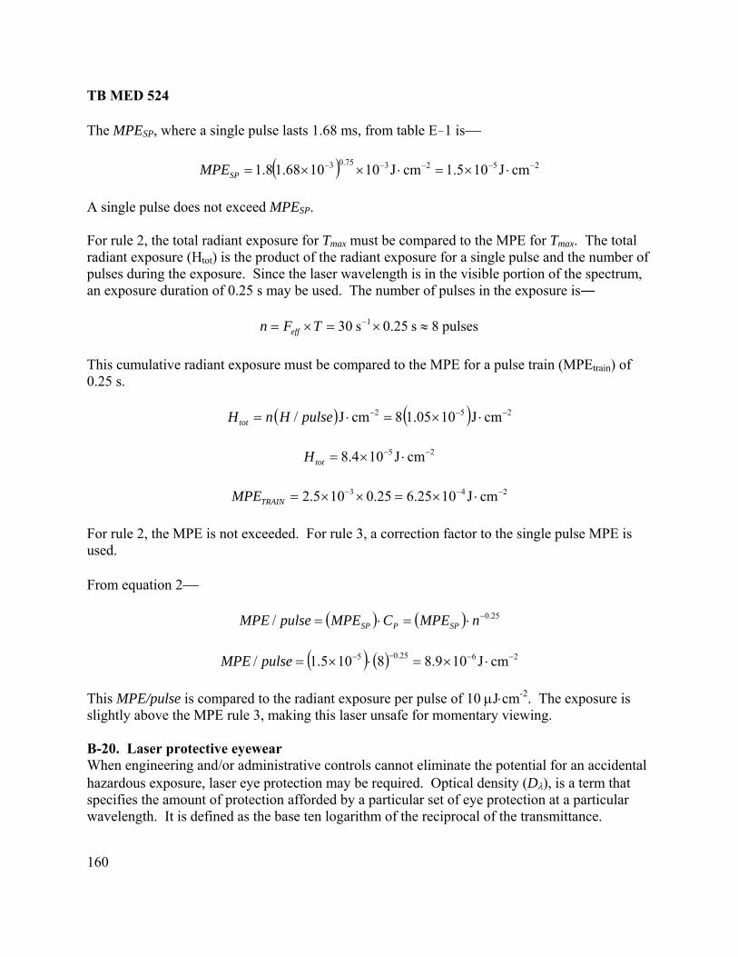
TB MED 524
160
he MPE , where a single pulse lasts 1.68 ms, from table E–1 is⎯
A single pulse does not exceed MPE For rule 2, the total radiant exposure for Tmax for Tm The tradian posure ( ) is th roduc the ra nt exp re for a single e and numb of pulses during the exposure. Since th ser w length in the ible p on of spect , an exposure duration of 0.25 s may be used. The num of pul in the osure
0.203 ×== Feff
This c lative radiant exposure must be co train)0.25 s
T SP
( ) 252375.03 cmJ105.1cmJ101068.18.1 −−−−− ⋅×=⋅××=MPE SP
SP.
must be compared to the MPE ax. otal t ex Htot e p t of dia osu puls the er
e la ave is vis orti the rumber ses exp is―
pulses8s5 ≈s 1−×Tn
umu mpared to the MPE for a pulse train (MPE of .
( ) 2 5 J−( ) 2 cm1058J −− ⋅×=⋅lseHnHt
J108 −−=tot
cm10525.10 −− ⋅×=×=TRAINM
For rule 2, the MPE is not exceeded r rul corr on fa to the gle p MPEused. From ⎯
0.1cm/ pu=ot
25 cm⋅4. ×H
24 J−3 0× 2.65.2PE
. Fo e 3, a ecti ctor sin ulse is
equation 2
( ) ( ) 25.0/ −⋅=⋅= nMPECMPEpulseMPE SPPSP
( ) ( ) 2625.05 cmJ109.88105.1/ −−−− ⋅×=⋅×=pulseMPE
is making this laser unsafe for momentary viewing.
ear When engineering and/or administrative controls cannot eliminate the potential for an accidental hazardous exposure, laser eye protection may be required. Optical density (Dλ), is a term that specifies the amount of protection afforded by a particular set of eye protection at a particular wavelength. It is defined as the base ten logarithm of the reciprocal of the transmittance.
This MPE/pulse is compared to the radiant exposure per pulse of 10 μJ⋅cm-2. The exposureslightly above the MPE rule 3, B-20. Laser protective eyew

TB MED 524
161
n 43 Equatio ⎥⎢⎡τ1g10 ⎦
⎤
⎣=
λλ loD
he ratio of the MPE to the r radiant exposure (H) at the laser exit port, at a given istance from the exit port, pil for a magnifying optic determines the necessary rotective transmission for a laser protective filter. The OD in terms of MPE is⎯
T irradiance (E) od or at the exit pup
Equation 44 ⎥⎤
⎢⎡=⎥
⎤⎢⎡=
HorED loglogλ ⎦⎣⎦⎣ MPEMPE
EXAMPLE 36. Alexandrite Calculate the worst-case OD required for protection against an alexandrite laser used in a hospital for tattoo removal. T le pulse output energy of 20 mJ, a pulse width of 50 ns, and the beam diameter is 6 mm.
755 nm is 1.29. This results in an MPE of 6.44× 10⁻⁷ J·cm-2. The worst- radiant energy at the laser exit port over the limiting of the beam diameter. At 755 nm, the limiting aperture is
.7 cm.
Laser.
he laser operates at 755 nm, has a sing
Solution. The MPE from table E–1 is⎯
27 cmJ105 −− ⋅×⋅= CMPE ASP
rom table E-3, CA atF
case OD is determined by averaging theperture for that wavelength regardless a
0
222 cmJ1019.5
cm0.385⋅×==H .
3 J1020 −−−×
Therefore, the worst-case OD is⎯
91.41044.61019.5log 7
2
=××
= −
−
λD
XAMPLE 37. Minimum Optical Density (0.5 J, Q-switched, Nd:YAG rangefinder).
alculate the minimum OD required for unaided viewing from a 0.5 J, Q-switched, Nd:YAG rangefinder at a distance of 1 km from the laser exit port. The laser has an initial beam diameter of 1 cm, a divergence of 1 mrad, and a pulse width of 20 ns. Solution. At a distance of 1 km, the beam diameter is—
E C

TB MED 524
162
( ) ( ) cm1001011010.1 23252 =××+= −DL
When the laser beam is larger than the limiting aperture (7 mm for 1064 nm) and optical aids are not used, the necessary OD is simply the log of t t exposure or irradiance at
m, the beam diameter were smaller than the limiting perture, then the method shown in the previous example would be used to calculate the OD.
he ratio of the radianthe given distance to the MPE. If, at 1 kaThe radiant exposure, at 1 km, from equation 6 is―
( ) 252 cmJ106.35
100πJ0.54 −− ⋅×==H
The MPE from table E–1 is 5 × 10⁻⁶ J⋅cm-2. The OD is―
⎥⎦⎤⎡ H
⎢=MPE
D logλ
⎣
1.1105
1035.6log 6
5
=⎥⎦
⎤⎢⎣
⎡××
= −
−
λD
Due to the possibility of atmospheric turbulence causing non-uniformitie in the beam, 1 OD unit should be added to the calculated OD, resulting in a final OD of 2.1. Intrabeam viewing of a
am viewing. Lasers operating at wavelengths greater than 2.8 mm generally are not ansmitted by optical instruments due to characteristics of the glass. If OD calculations are
r beam diameter is smaller than the entrance aperture diameter of the optical id, then the method used in example 36 is used to calculate the OD.
EXAMPLE 38. Minimum Optical Density (0.1 W tactical laser pointer). Calculate the minimum OD necessary to safely v tactical laser pointer operating at
s
laser through optical aids generally increases the potential hazard when compared to unaided intrabetrmade where the lasea
iew a 0.1 W860 nm, at a range of 75 m. The initial beam diameter of the laser is 7 mm, and it has a divergence of 2 mrad. Assume the laser is being viewed with 7×50 binoculars that transmit 70 ercent at the laser wavelength. p
Solution. The beam diameter (DL) and the irradiance (E) at 75 m is⎯
( ) ( ) cm16102cm7500cm0.7 3 ≈×⋅+= −LD
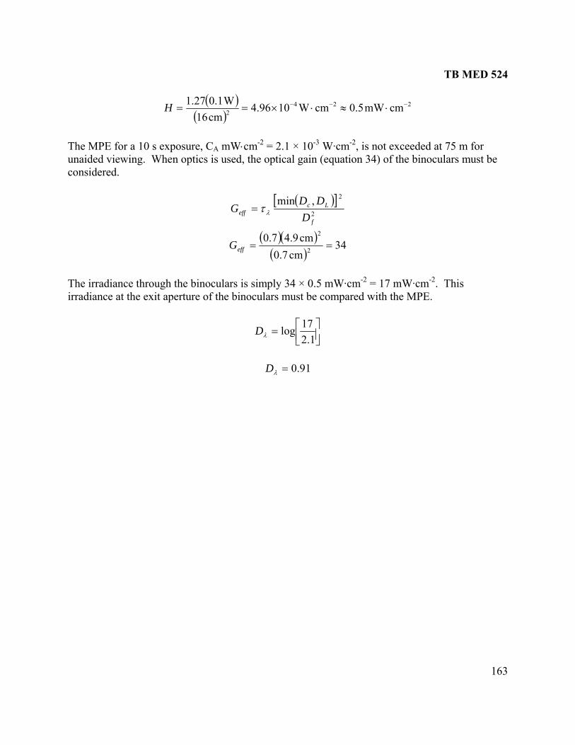
TB MED 524
163
( )( )
224 cmmW0.cmWc16
W0.11.27 −−− ⋅≈⋅=H
2 5104.96m
×=
The MPE for a 10 s exposure, CA mW⋅cm-2 = 2.1 × 10⁻³ W·cm-2, is not exceeded at 75 m for unaided viewing. When optics is used, the optical gain (equation 34) of the binoculars must be considered.
( )[ ]2
2,min
f
Lc
DDD
λτ= effG
( )( )( )
34cm0.7
cm9.40.72
2
==effG
d with the MPE.
The irradiance through the binoculars is simply 34 × 0.5 mW·cm-2 = 17 mW·cm-2. This irradiance at the exit aperture of the binoculars must be compare
⎥⎦⎤
⎢⎣⎡=
1.217logλD
91.0=λD

TB MED 524
164
This page intentionally left blank

TB MED 524
165
APPENDIX C
MEDICAL SURVEILLANCE C–1. Introduction a. The U.S. Army laser medical surveillance program is the ongoing, systematic collection,
analysis, and interpretation of data essential to the planning, implementation, and evaluation of Army force health. Medical surveillance as implemented in this document refers to occupational medical surveillance, which is the monitoring applied to individual workers based on actual or presumed workplace exposures. b. Medical surveillance is required for personnel working w lass 3b and Class 4 lasers and laser systems and is not a requirement for those personnel working with Class 1, Class 2, or
a. Preemployment vision screenings. Performed at or just prior to employment to provide a baseline visual performance measurement and to assist in appropriate job placement. This is part of the preemployment physical. b. Preplacement vision screenings. Performe ajor change of job duties or change to a new job that has a significant change of duties. Permanent change of station with no significant change of duties does not require an additional screening. c. Termination vision screenings. Performed at or just prior to separation from government employment for employees who have worked in an eye-hazardous job or area. d. Vision screening results. Results will be placed in the individual’s health record. The record will reflect the purpose of the vision screening, the results, and any required follow up. The record should document the following: (1) Demographic information— (a) Employee’s name. (b) Social security number. (c) Organization or unit. (d) Duty position or occupation. (e) Job vision standard. (f) Eye protection requirement (if any). (g) Reason for screening (pre-employment, preplacement, problems, or termination). (2) Clinical information― (a) Vision screening test results. (b) Evaluation of screening results. (c) Disposition (such as, cleared for duty, refer for further evaluation, or release).
ith C
Class 3a lasers or laser systems. See DA Pam 40–506 for detailed information.
–2. Employment status and vision screening C
d when there is a m

TB MED 524
166
C–3. Classification of laser workers a. Laser workers. Laser workers are those ind ls who routinely work in a laser environment having Class 3b a e a higher risk of accidental overexposure. Laser workers include those who regularly perform laser research, development, testing and evaluation; individuals who work with or near medical lasers found in operating rooms; and workers who perform routine laser maintenance. Laser workers have a moderate to high risk potential for laser injury. b. Incidental laser workers. Incidental laser workers are those individuals whose work makes it possible, but unlikely, that they will be exposed to laser energy that could damage the eye. Incidental workers include operators of fielded laser equipment, individuals who oversee laser use on approved laser ranges, and Soldiers who participate in Force-on-Force laser training exercises. Incidental laser workers are considered to have low risk potential for laser injury. (Note: Laser workers and incidental laser workers are essentially equivalent to laser personnel and incidental personnel as defined in ANSI Z136.1 and laser personnel and incidental healthcare personnel as defined in ANSI Z136.3.) C–4. Laser medical surveillance/assessment Medical assessments will be performed for individuals involved with lasers per ANSI Z136.1 and Z136.3. a. Laser workers (laser personnel). Laser workers will have an ocular and visual history, visual acuity (VA), color vision test, and a central visual fields test (via Amsler Grid or similar macular integrity test) at preplacement and termination. VA, color vision test, and central field tests are to be performed on each eye separately. If the worker’s distance VA is 20/20 in each eye, color vision test is normal, central visual fields normal via Amsler grid test or similar macular integrity test, and medical history is normal for the eyes, no further examination is required. Any deviation from the acceptable normals will be evaluated to determine the reason. This may be done by ocular funduscopic examination or other tests as deemed appropriate by the eye care professional. b. Incidental laser personnel (incidental healthcare personnel). Incidental laser workers will have each eye screened for VA. This screening is part of the pre-employment physical. C–5. Protective measures required a. Laser workers are required to wear wavelength-specific laser-protective goggles whenever a Class 3b or Class 4 laser is in use. In addition, the OD of the filtering lenses must be capable of reducing the power of the incident laser beam to a level safe to view. Refer to MIL–HDBK–828A to find the wavelength and OD requirements for laser eye protection when using military laser equipment. In addition to PPE, laser work areas should be set up according to procedures outlined in ANSI Z136.1 unless the LSO establishes other criterion based on the specific laser and laser operation. b. Incidental laser workers do not require laser protective goggles unless the LSO, the installation safety officer, or the installation Vision Conservation and Readiness Officer deem it necessary. (Note: Filters and some materials used in laser protective equipment tend to darken and crack with time (that is, long-term storage)). They also may provide less protection after
ividuand Class 4 lasers and, therefore, hav

TB MED 524
167
repeated exposure to laser emission. Th ted representative should inspect the equipment periodically for integrity of the protective devices and lenses as well as the ability to filter the laser radiation (ANS
–6. Emergency care for laser injury OD employee with a confirmed or suspected, unprotected exposure to a
of (or authorized
ndividuals with confirmed exposure will be
r
e LSO or a designa
I Z136.1)). C a. Any soldier or DClass 3b or more powerful laser will have a diagnostic vision examination as soon as possible (no later than 24 hours) by an optometrist or ophthalmologist at the nearest military treatment facility (MTF). Documentation of the injury will include a history of the event and a thorough vision and ocular examination. The examination is required to include ocular history, distance VA, Amsler grid (or similar central visual field) test, slit lamp examination, ocular fundus evaluation through dilated pupil, ocular fundus photographs that depict the extent of injury or lack of injury, and photographs of any external or anterior segment injury. b. If ophthalmic photographic capabilities are not available, then a detailed representation the finding may be hand-drawn or the patient will be referred to the nearest MTFlocal civilian provider) having such capabilities. Iexamined by a retinal specialist. C–7. Reporting a. Once the optometrist or ophthalmologist suspects or confirms an acute laser overexposure incident, he/she will notify— (1) The division/installation LSO. (2) The division/installation RSO. (3) The Tri-Service Laser Incident Hotline (DSN 240–4784 or commercial (210) 536–4784 o80 – [email protected] 473–3549) (email: laser ). (4) The USACHPPM LORP (DSN 584–3932/2331 or commercial (410)-436-3932/2331 or 800-222-9698) (e-mail: [email protected]). (5) The USACHPPM Tri-service Vision Conservation and Readiness Program (TVCRP)
ercial (410) 436–2714) (e-mail: il
Manager (DSN 584–2714 or [email protected] ). After normal duty hours, contact the USACHPPM personnel
584–4375 or commercial (410) 436–4375 or 800–222–9698). l include— l security number.
me of the incident. uation.
question. ote: Do not send the laser equipment to maintenance for repairs.) The USACHPPM LORP
ill initiate a technical evaluation of the incident and of the laser equipment involved and will render a technical report as soon as possible after the incident. The USAMRD–WRAIR Ocular
via the staff duty officer (DSN b. Information to be reported wil (1) Patient name, grade, and socia (2) Unit name. (3) Hospital providing care and registration number.
e. (4) Exposure date and sourc (5) Duty being performed at the ti (6) Summary of symptoms and eval (7) Any follow-up information. c. The installation RSO, with the help of the safety office, will secure the laser in (Nw
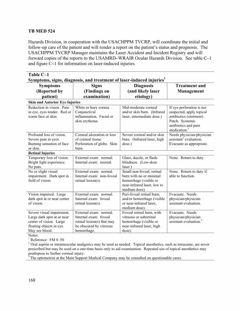
TB MED 524
168
he USACHPPM TVCRP, will coordinate the initial and is. The
Hazards Division, in cooperation with tfollow-up care of the patient and will render a report on the patient’s status and prognosUSACHPPM TVCRP Manager maintains the Laser Accident and Incident Registry and will forward copies of the reports to the USAMRD–WRAIR Ocular Hazards Division. See table C–1and figure C–1 for information on laser-induced injuries. Table C–1 Symptoms, signs, diagnosis, and treatment of laser-induced injuries1
Symptoms (Reported by
patient)
Signs (Findings on examination)
Diagnosis (and likely laser
etiology)
Treatment andManagement
Skin and Anterior Eye Injuries Reduction in vision. Pain in eye, eyes tender. Red or warm face or skin.
White or hazy cornea. Conjunctival inflammation. Facial or skin erythema.
Mid-moderate corneal and/or skin burn. (Infrared la
If eye perforation is not suspected, apply topical
ser, intermediate dose.) antibiotics (ointment). Patch. Systemic antibiotics and pain medication.2
Profound loss of vision. Severe pain in e
Corneal ulceration or loss Severe corneal and/or skin Needs physician/physicyes. of corneal tissue. burn. (Infrared laser, high
ian assistant3 evaluation.
te. Burning sensation of face or skin.
Perforation of globe. Skin burn.
dose.) Evacuate as appropria
Retinal Injuries Temporary loss of vision. Bright light experience. No pain.
External exam: normal. Internal exam: normal.
Glare, dazzle, or flash-blindness. (Low-dose laser.)
None. Return to duty.
No or slight visual impairment. Dark spot in field of vision.
External exam: normal. Internal exam: non-foveal retinal lesion(s).
Small non-foveal, retinal burn with no or minimal hemorrhage (visible or near-infrared laser, low to
None. Return to duty if able to function.
medium dose). Vision impaired. Large dark spot at or near center
External exam: normal. Internal exam: foveal
Peri-foveal retinal burn, and/or hemorrhage (visible
Evacuate. Needs physician/physici
of vision. retinal lesion(s). or near-infrared laser, medium dose).
an assistant evaluation.
Severe visual impairment. Large dark spot at or near center of vision. Large floating objects in eye. May see blood.
External exam: normal. Internal exam: foveal retinal lesion(s) that may be obscured by vitreous hemorrhage.
Foveal retinal burn, with vitreous or subretinal hemorrhage (visible or near-infrared laser, high dose).
Evacuate. Needs physician/physician assistant evaluation.2
Notes: 1 Reference: FM 8–50 2 Oral aspirin or intramuscular analgesics may be used as needed. Topical anesthetics, such as tetracaine, are neveprescribed but may be us
r ed on a one-time basis only to aid examination. Repeated use of topical anesthetics may
predispose to further corneal injury. 3 The optometrist at the Main Support Medical Company may be consulted on questionable cases.
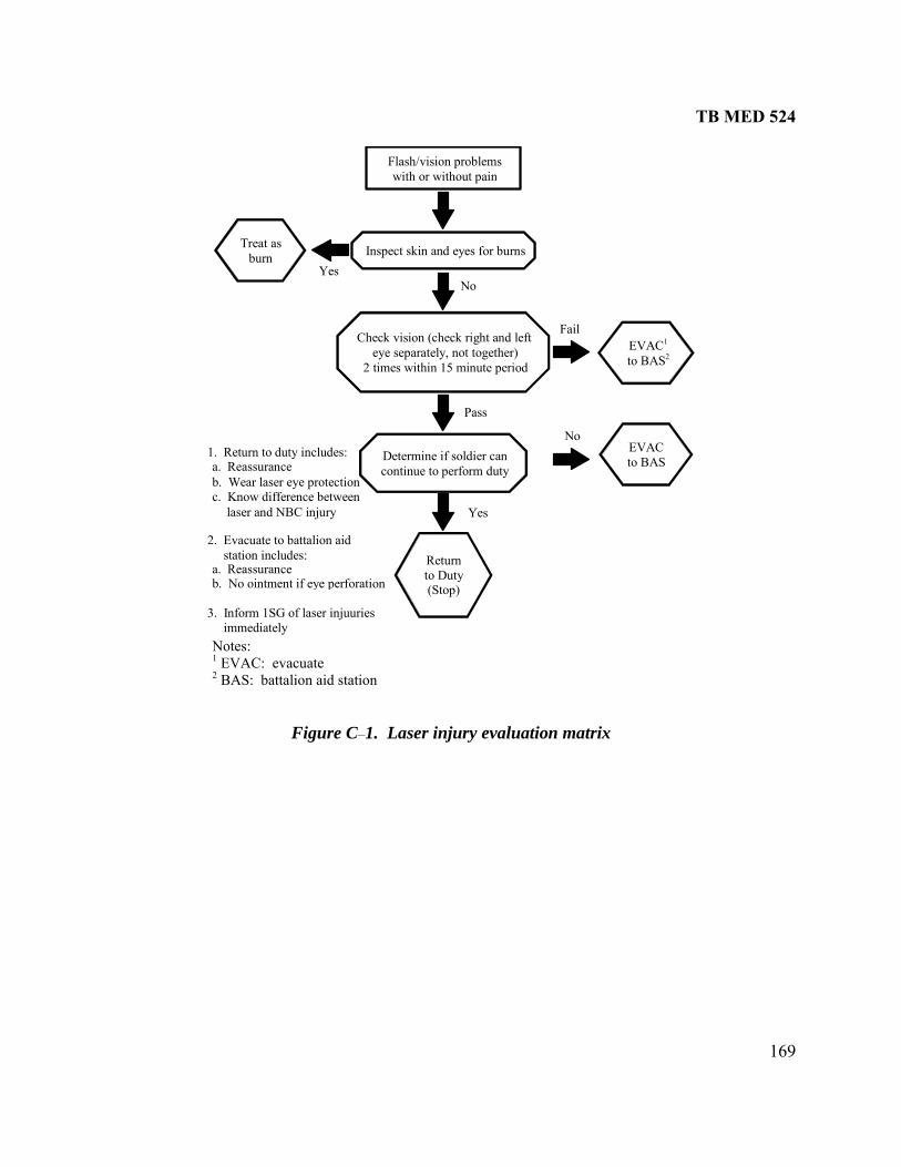
TB MED 524
169
Flash/vision problemswith or without pain
Treat asburn Inspect skin and eyes for burns
Check vision (check right and lefteye separately, not together)
2 times within 15 minute period
Determine if soldier cancontinue to perform duty
Returnto Duty(Stop)
EVAC1 to BAS2
Yes No
Fail
Pass
Yes
No 1. Return to duty includes: a. Reassurance b. Wear laser eye protectio c. Know difference betw
EVAC to BAS
neen
ser and NBC injury la
2. Evacuate to battalion aid station includes: a. Reassurance b. No ointment if eye perforation
3. Inform 1SG of laser injuuries immediately Notes: 1 EVAC: evacuate 2 BAS: battalion aid station
Figure C–1. Laser injury evaluation matrix

TB MED 524
170
This page intentionally left blank

TB MED 524
171
APPENDIX D
SAMPLE SAFETY GUIDELINES
D–1. Introduction The following information contains proposed guidelines to ensure that safety precautions are followed, adequate surveillance is provided, required protective eyewear is worn, and communication with personnel is maintained within established target areas. Each guidelines is a stand-alone document, and it is advisable to implement these guidelines as SOPs. D–2. Scope The LRSO/LRSNCO should refer to these guidelines to ensure that all personnel are thoroughly instructed on safety precautions.

TB MED 524
172
This page intentionally left blank

TB MED 524
173
D–3. Safety guidelines for ocular safety in healthcare facilities a. Purpose. To prevent ocular injuries to patients receiving laser treatment or to healthcare personnel (HCP) working b. Policy. Within the no adhere to appropriate eye
ations. Under some conditions, the NHZ may ccupy the entire room in which the laser procedure is performed. Under those conditions, the cular safety procedures listed below apply to the entire room. Service personnel, biomedical
e involved in demonstrations of equipment will follow all ocular safety
al density to revent ocular damage at the laser wavelength in use. Exception to this is the operator looking
tached microscope with a lens that has the appropriate optical density for the laser
d ancillary personnel will be responsible for selecting and xamining eyewear for comfort, proper fit, and presence of labels describing both wavelength
and proper optical density. (3) If eyewear is damaged, it must not be worn; a report must be made to the Laser Safety Officer. (4) Contact lenses are not acceptable as protective eyewear. Prescription lens wearers must use appropriate laser safety eyewear. (5) All goggles must have side shields to protect from peripheral injury and impact. (6) Any articulated arm that is not shuttered must be capped when not connected to the hand piece or the operating microscope. (7) The laser system must be placed in standby mode when delivery optics is moved away from the target. (8) Patients will be fitted with appropriately labeled eyewear or have their eyes covered with wet cloth pads or towels. Metal or dry materials will be placed on the patient's face or eyes only when indicated.
with Class 3b and Class 4 lasers. minal hazard zone (NHZ), all personnel will
protection procedures during all laser applicootechnicians, and thosprocedures whenever a laser is in operation in the facility. c. Procedures. (1) Appropriate eyewear will be worn by all personnel in the NHZ while the laser is in operation. Appropriate eyewear consists of glasses or goggles of sufficient opticpthrough an atin use. (2) Prior to use, the operator ane

TB MED 524
174
This page intentionally left blank

TB MED 524
175
t system and related optical
l
ible exposures (MPEs) for laser
er
or if the devices are deliberately misused. the
to any user of the MILES or AGES/AD equipment or personnel
clude the material contained in this guideline.
r tube
blank activated.
and pulse codes determine the effectiveness of each weapon type and distinguish between a hit, kill, or near-miss. The beams are small and well collimated to allow use over extended distances. Detector belts located on vehicles and individuals respond to the infrared pulses and produce either an audible or visual indication of detection. Optical hazards from MILES devices are limited to eye exposure to the direct beam or from the beam deflected by a mirror. Diffuse or specular reflections from ordinary glass or other surfaces are not hazardous. (2) Most MILES devices have a nominal ocular hazard distance (NOHD) of 10 m or less. A few have an increased hazard distance when binoculars are used to view the laser from within the direct beam. Laser protective eyewear should only be used when administrative controls are inadequate. Almost all MILES devices have a hazard classification of 3a or less. Some MILES devices are Class 1 and do not pose an eye hazard. Class 3a devices exceed the Class 1 accessible emission limit by no more than 5 times.
D–4. Safety guidelines for multiple integrated laser engagemenequipment for maintenance workers a. Warning. (1) Laser training devices, such as Multiple Integrated Laser Engagement System (MILES) or the Air to Ground Engagement System/Air Defense System (AGES/AD), present an opticaviewing hazard even though the laser emission is invisible. These devices do not present as serious a hazard as laser rangefinders and designators, which can produce irreparable blindnessfrom one accidental exposure. However, exposure to the direct output from the laser within afew meters exceeds currently established maximum permissdevices. (2) Although immediate blindness would be unlikely from these MILES devices and othtraining systems, any possibility of potential injury involving the soldiers’ eyes should be avoided. During training, checkout, or maintenance, the MILES or AGES/AD devices could produce an exposure exceeding the MPE if the devices are used by persons unaware of the hazards b. Training Procedures. The following steps should be taken to prevent overexposure to laser energy: (1) Provide safety trainingrequired to activate the transmitters during checkout or maintenance. The content of the training should in (2) Never intentionally fire any hand-held weapon system at a person's face within 10 meters (m) during a training exercise. (3) Never point and fire any large-gun MILES device, such as a tank gun simulator olaunched, optically tracked, wire guided (TOW) missile, at anyone's face within 10 m during a training exercise. (4) Goggles are recommended for users if small arms MILES devices are used with firing cables rather than c. General Information. (1) The MILES transmitters emit a beam of infrared light pulses in a coded sequence. The energy per pulse

TB MED 524
176
(3) The beam from some of the small arms tran mitters (SATs) is slightly focused. Therefore, the hazard at 2 or 3 m from the device may be greater than at the exit port since most of the emitted energy could enter an i stems may exceed the MPE by 10 times or more close to the laser exit port. The output energy per pulse varies between individual devices due to system requirements. (4) When the MILES transmitters are mounted to hand-held weapons and are used with blank ammunition, a hazard exists a few meters along the line of sight from the wadding. Hazards from MILES devices are based on a 10-second exposure duration. A shorter exposure duration lessens the hazard but does not eliminate it. Movement of the weapon system immediately after firing would prevent the laser from delivering all the laser pulses fired to a person's eye. Large guns generally use weapon effects simulators in addition to MILES, and the beams are often above normal eye level, thus, reducing the injury potential. Since an exposure exceeding the MPE would be unlikely during a training exercise, the MILES systems were deemed "safe for field use." Laser goggles were not deemed necessary for field training. (5) In 1986, the SAT for the M16 was redesigned for a smaller size, lower-energy emission, and the addition of boresight controls on the MILES device. The hazards from that design approach but do not exceed the MPE. Several styles, models, and generations of the SAT are currently in use, most of which exceed the MPE within a few meters of the device (usually no more than 10 m for unaided viewing). Therefore, caution is recommended when training at close engagement distances. d. Maintenance Procedures. (1) Develop a standing operating procedure (SOP) for all transmitter maintenance tasks; ensure that maintenance personnel are familiar with it and follow the SOP. (2) Do not allow personnel in the maintenance area who are unaware of the MILES optical hazards. (3) Ensure that personnel maintaining equipment are aware that the direct beams from MILES devices are hazardous within 10 m. (4) Never point an operational MILES device at your face or the face of another person. (5) Position the MILES transmitter so that the beam is horizontal, below eye level, and terminated into a diffuse surface before turning the device on. This precaution is especially important for malfunctioning devices. (6) Make sure that the MILES transmitter is off before transporting it to a new location. (7) Use laser protective eyewear when facial exposure to the direct beam cannot be avoided. Laser protective goggles with an optical density of at least 2.0 at 905 nanometers or a 3-millimeter thickness of Schott KG–3 glass is sufficient.
s
ndividual's pupil. Some airborne sy
TB MED 524
177
for individual applications and unit requirements.) er rangefinders and designators can cause irreparable eye injury and possible
r operators shall never point the laser at any unprotected personnel or flat, mirror-like
vered by an opaque dust cover and will be
identify the target and buffer areas prior to laser operations. ith
ved lenses.
ater begins ponding either on the open ground or on snow.
may be taken.
D–5. Safety guidelines for training with portable fire control lasers (Note: This guideline should be tailored a. Warning. Lasblindness if used improperly. Exposure of the eye to either the direct beam or a beam reflected froma flat mirror-like surface could cause an injury at a great distance. b. Reference. Army Regulation (AR) 385–63, Range Safety. c. Control Measures. The following control measures will prevent hazardous exposure when training operators with portable fire control lasers in one-sided exercise: (1) Laser operators shall periodically read and always follow this safety guideline. (2) Lasesurfaces such as glass. (3) Laser operators should operate only on laser-approved ranges established according to AR 385-63. (4) The laser will not be operated or experimented with outside the range area unless it is specifically authorized. The laser exit port will be codisabled by removal of the battery when the laser is located outside the range area. (5) Positively (6) Laser eye protection is not required for laser operators even when viewing the target area wbinoculars. However, operators should never enter into the laser target area without appropriate laser eye protection. Such eye protection should have cur (7) No special precautions are necessary for firing during rain, fog or snow fall. Certain ranges may be closed for operation if w (8) Laser operators should report immediately to their supervisor any suspected injury or defective equipment (such as, misalignment of the laser beam with the pointing telescope) so that appropriate action

TB MED 524
178
This page intentionally left blank

TB MED 524
179
)
t beam or a beam reflected from tance.
en operating tactical laser pointers: for the
e laser-approved area.
e target
tactical pointers, such as 100 milliWatt (mW) models of the CP, are considered hazardous at 10 percent of the total laser power (approximately 4-8 mW into
the eye is considered the threshold for ocular injury). However, the risk of a laser eye injury to the operator while directing the laser beam through an aircraft canopy is considered small and is nonexistent with Class 1 or Class 3a lasers. (8) Due to the geometry of the devices, night vision goggles (NVGs) should not be relied upon as a substitute for laser eye protection. With certain NVG devices, it is possible to be potentially exposed to a hazardous laser beam from an indirect line of site when the NVG devices do not fit snugly against the face. (9) Do not illuminate unprotected personnel. However, under certain circumstances such as Force-on-Force training, it may be authorized to illuminate individuals or vehicles, but these individuals should be informed they might be lased. Individuals should never enter into the laser target area (within the nominal ocular hazard distance) without appropriate laser eye protection. Laser eye protection should be chosen to reduce the laser exposure to Class 1 levels during training and Class 3a levels during tactical situations. Eye protection for Class 3b and Class 4 lasers shall have curved lenses to prevent hazardous back reflections from the eye protectors. (10) The output power of laser-aiming devices shall be limited to preclude operation above Class 3a during Force-on-Force training. Any Class 3b product must be attenuated or otherwise controlled to limit emission to Class 3a or below (sometimes referred to as the training mode).
D–6. Safety guidelines for training with tactical laser pointers (Note: This guideline should be tailored for individual applications and unit requirements.) a. Warning. Class 3b Tactical Laser Pointers (such as the Ground Commander’s Pointer (GCP(Airborne Infrared Multipurpose–1), Air Commander Pointer, and AN/PEQ-2/2A) can cause eye damage if used improperly. Exposure of the eye to either the direca flat mirror-like surface could cause an injury even at a great dis (1) Note 1: The AN/PAQ–4 tactical laser pointer, in A, B, or C versions, is categorized as a Class 1 system and does not pose a hazard under any viewing condition. (2) Note 2: Class 4 pointing lasers should not be used even in combat. (3) Note 3: This guideline does not apply to commercially available classroom visible laser pointers. b. Control Measures. The following control measures will minimize the chance of a hazardous exposure wh (1) Equipment should only be operated by personnel who have received proper trainingoperation of the laser. Refer to operator’s manual for startup and firing procedures. (2) Laser operators shall periodically read and always follow this safety guideline. (3) Operate only in laser-approved areas. (4) The laser will not be operated or experimented with outside the laser-approved area unless it is specifically authorized. The laser exit port will be covered by an opaque dust cover and/or the laserdisabled by removal of the battery when the laser is located outside th (5) Positively identify the target and buffer areas prior to laser operations. (6) Generally, laser eye protection is not required for laser operators even when viewing tharea with binoculars. (7) Glass-like surfaces, such as an aircraft canopy, can reflect 10 percent or more of the laser energy. For example, high-powerG

TB MED 524
180
Methods to reduce emission include removable at nuation filters and mode selector switches; however, attenuation control methods should requ special tool to deactivate the attenuation. Common tools, such as a screwd pose. Additionally, the laser device should clearly indicate that the training mode is selected. (11) No special precautions are necessary for firing during rain, fog, or snowfall. (12) Report immediately any suspected injury or defective equipment to your chain of command so that appropriate action may be taken.
teire a
river, are not acceptable for this pur

TB MED 524
181
control lasers
also pose a skin hazard. g
r operators shall never direct the laser at unprotected personnel.
edure.
covered by ted outside the
d.
is marked with its
ts or alarms to the closed area.
r any suspected injury or defective equipment so that
D–7. Safety guidelines for maintenance shop operation of fire(Note: This guideline should be tailored for individual applications and unit requirements.) a. Warning. Laser rangefinders and designators can cause irreparable eye injury and blindness if used improperly. Exposure of the eye to either the direct beam or a beam reflected from a flat mirror-like surface could cause an injury to the unprotected eye. Class 4 lasers may also pose a potential hazard when viewing a diffuse reflection of the beam and may b. Control Measures. The following control measures will prevent hazardous exposure durinlaser operations in the maintenance shop: (1) Maintenance personnel shall periodically read and always follow this safety guideline. (2) Only those operations authorized in appropriate maintenance manuals shall be permitted. (3) Lase (4) Laser operators shall wear laser protective eyewear whenever the laser is operated with an unenclosed beam and then use a countdown proc (5) Laser operators shall operate the laser from within an approved area that is closed such that no line-of-sight exists to unprotected personnel outside the area. The laser exit port will bean opaque dust cover, and the battery will be removed from the device when it is locaclosed area unless it is specifically authorize (6) Prior to laser operations, maintenance personnel shall complete the following checklist: (a) Periodically test door electrical interlock switches at entrances. It is not a good safety practice to lock access doors. (b) Select appropriate laser protective eyewear. Ensure that eye protectionprotective characteristics. (c) Test warning ligh (d) Post a warning sign at entrances to the closed area. (e) Ensure that any other required safety devices are available. (f) Ensure that beam path is clear of potentially reflective materials. (7) A lens used to focus the laser beam of Class 3 and Class 4 lasers will increase the eye hazards from diffuse reflections and the skin hazards around the focal point. (8) Report immediately to your supervisoappropriate action may be taken.

TB MED 524
182
This page intentionally left blank

TB MED 524
183
, Laser Safety on Ranges and in Other Outdoors Areas.
trict compliance with
sioned Officer (LRSO/NCO) who has
ets and target areas daily prior to laser operations commencing and after no
around the target according to TB MED 524 and that no one is and communication. The Range Control
d according to range control
io is available at the range
ualty receives immediate treatment at a medical cility (that is, unit has 24 hours to get suspected casualty to medical facility) according to TB
MED 524. (g) Ensure that no one is allowed downrange unless they have the proper equipment and communication. (h) Ensure that the laser surface danger zone is accurate. (i) Be familiar with all appropriate publications concerning lasers, in particular TB MED 524 and MIL–HDBK–828A. (j) Depending on how local regulation stipulates, coordinate with the Range Control Officer concerning Notice to Airman and announcements in the Daily Bulletin. (k) Coordinate with safety office prior to start of laser operation (3) Units. Units conducting laser operations will⎯ (a) Ensure that the exit port of the laser is covered by an opaque cover when not operational or when traveling to and from ranges.
D–8. Safety guidelines for laser operations a. Purpose. This guideline prescribes the policies and procedures for laser operations. b. Objective. To properly control the use of all laser operations except the Multiple Integrated Laser Engagement System (MILES) devices during training. c. References. (1) Technical Bulletin, Medical (TB MED) 524, Control of Hazards to Health from Laser Radiation. (2) Military Standard (MIL–STD)–828A (3) Field Manual (FM) 8–50, Preventive and Medical Management of Laser Injuries. d. Responsibilities. (1) Commander. Commanders at all levels are responsible for ensuring sgood safety practices during laser operations. Commanders will⎯ (a) Appoint a Laser Range Safety Officer/Noncommissuccessfully completed the Laser Safety Course provided by the Safety Office, Radiation Safety Officer (RSO), or Range Control Officer. This training should be updated as required by the RSO or Range Control Officer. (b) Establish a written guideline. (2) LRSO/NCO. The LRSO/NCO will⎯ (a) Be present at all times during laser operations. (b) Inspect laser targadverse weather conditions (that is, rain or ice storms). This inspection will ensure that there arespecular (reflective) objects on ordownrange without the appropriate protective equipmentOfficer may decide to record a log of these inspections. (c) Ensure that all signs and barricades are properly positioneguidance at least 24 hours prior to operations. (d) Ensure that a safety briefing is given prior to laser operations. (e) Ensure that a copy of the range regulation and live-fire scenarsite, if applicable. (f) Ensure that any suspected or actual laser casfa

TB MED 524
184
(b) Ensure that laser operators have positively identified the target prior to lasing. (c) Ensure that the use of optical devices is coordinated with the LRSO/NCO and Range Control Officer. (d) Coordinate with the Range Control Officer to ensure that other units on adjacent ranges are aware that laser operations are being conducted and that adjacent units do not use magnified optics to observe the laser operations. e. Additional laser Information. (1) The laser system, except for its inability to penetrate targets, will be treated as a direct fire, line-of-sight weapon such as a rifle or machine gun. (2) The use of optical devices to observe the target during laser operations will not be permitted unless flat, specular surfaces have been removed from the target area or unless appropriate laser safety filters are placed in the optical train of the binoculars, telescope, or laser itself. (3) All targets planned for laser engagement will be inspected by a qualified Laser Safety Officer (LSO) prior to initial use. Only targets and target areas approved by the LSO and Range Control Officer will be engaged with lasers. The LRSO/NCO will reinspect all approved targets and target areas prior to each day’s operation and after adverse weather. (4) First-aid will comply with FM 8–50.

TB MED 524
185
Table D–1 Precautions/Danger areas for laser systems1
Laser System Area T Area S NOHD NOHD2 Static Buffer
Moving Buffer
AN/VVG-33
M10 60M 7K 35K 2 mils 5 mils
Tank AN/GVS-54
(hand held) trainingmove.
0 200M 2.7K 13K 10 mils Cannot use in on the
TADS5 (Apache) 0 200M 26K 70K 5 mils 5 mils 1 2
MMS6 (OH-58D) 0 200M* 35K1 80K2 2-5 mils 5 mils LAAT7 (Cobra) 0 60M 5K1 30K2 2-5 mils 5 mils
AN/TVQ-2 G/VLLD8
(designator) 0 60M 25K 80K 2 mils Cannot use in
training on the move.
Notes: 1 Reference: MIL–HDBK-828A
istances are worst-case (multiple pulse) isible Light, Fire Control
g (range and bearing)
2 These distances may change and these d3 AN/VVG: Army Navy/Ground Vehicular, V4 AN/GVS: Army Navy/Ground, Visible Light, Detectin5 TADS: Target Acquisition Designation Sight 6 MMS: Mast-Mounted Sight 7 LAAT: Laser Augmented Airborne Tube Launched, Optically Tracked, Wire Guided (TOW) 8 G/VLLD: Ground/Vehicle Laser Locator Designator

TB MED 524
186
This page intentionally left blank

TB MED 524
187
D–9. Safety guidelines for laser ranges (N ould be tailored for individual applications and unit requirements.) a (1) vol ase ion i lase tors, m e personnel, and range control personnel shall periodically read and alwa this sguideli (2) Appropriate personnel shall ensure equipment is only operated by personnel who have receive aining for the operation of the laser. (3) Appropriate personnel shall ensure that a laser range evaluation for a spec em or gr s been nducte e ran ing us b. (1) ional St dards In e (AN 136.1 Use rs. ( d (MI STD)– Saf esign ireme M s and Associated Support Equipment. c. Laser Range Evaluation. (1 aser for use on a range, one must determine the hazard potential of t (a vided by ANSI Z136.1. (b STD 1425A to determine lase ented. (c ting laser to the (d) Reflections. Determine if the laser is capable of producing hazardous specular and/or diffuse
reflections. (e) Optical density (OD). Determine the degree of protection required to reduce the incident laser energy to safe eye and skin levels. (f) Optically aided viewing. Consider the possibility of personnel viewing the laser beam or a reflection from the beam with optical instruments such as binoculars. (Note: These types of devices can increase the degree of hazard to the eye significantly, thus, increasing the NOHD and necessary OD.) (g) Atmospheric attenuation. Atmospheric attenuation can be quite high for lasers operating at ranges greater than 10 kilometers, reducing the NOHD considerably. (h) Laser platform stability. The stability of the laser platform is needed to determine the pointing accuracy of the laser. Pointing accuracy determines the size of the buffer angle. (2) Range. A range map, topographic map, and an air space map are required for a laser range evaluation. (a) Range map. The range map is used to establish accurate distances to the target area and range boundaries. This map should also include the locations of targets and also items such as buildings and towers. (b) Topographic map. This is important because it enables the test director to determine target elevations, as well as natural backstops such as hills that can be used to control the beam. (c) Airspace map. This map includes airspace associated with the range having specific, possibly non-coincident lateral boundaries and a specific minimum and maximum altitude.
ote: This guideline sh. Procedures.
All personnel in ved in a l r evaluat /exercise ncluding r opera aintenancys follow afety
ne.
d proper trific laser syst
oup of lasers ha co d on th ge be ed. References. American Nat an stitut SI) Z , Safe of Lase
2) Military Standar L– 1425A, ety D Requ nts for ilitary Laser
) Test laser. To evaluate a lhe system by determining the following: ) Maximum permissible exposure (MPE) limits. MPEs as pro)
ed to be implem Laser classification. Classify the laser using procedures in MIL
r control measures that ne) Nominal ocular hazard distance (NOHD). Determine the distance from the operapoint where the laser is no longer an eye hazard.

TB MED 524
188
(d) Target and target area. The size, location, and type of targets to be fired at are important in determining the hazard zone. (3) Mission. An evaluation m r used on the range. The laser operating mode (that is, air-to-ground, ground-to-ground, ship-to-target, and so forth) must be determined. (4) Laser surface danger zone (LSDZ). The LSDZ (also called the buffered laser footprint) must be determined. (5) Laser-user-level instructions. Utilizing the laser range safety evaluation, the Laser Safety Officer/Radiation Safety Officer will determine the necessary information to⎯ (a) Review and ensure that range safety regulations are current. Regulations should be developed or updated as necessary to take into account new laser systems, operating areas and targets. (b) Develop a guideline for specific laser operations to inform laser users of the potential hazards from the laser device. A guideline should be prepared concerning procedures for a pre-sweep of the range before laser operation to ensure that unprotected personnel are not in the target area for such things as maintaining radio communications. (c) Brief personnel involved in the laser operation to provide an understanding of the hazards of laser beams to humans and misconceptions about laser effects, principles of reflection and refraction of light, safety standards, and preparation of the range for laser use. (d) Prescribe the personal protective equipment including the proper eye protection optical density requirements for worst-case exposure to the laser.
ust be completed for each type of lase

TB MED 524
189
ce training with tactical and training lasers lasers
orce training.
chain of who is responsible for all laser issues at the operational level. It includes but is not
the facility that the appropriate operational
ard zone (NHZ). The NHZ is the designated region on the ground and in air (MPE) level.
diance (W·cm ) or radiant exposure (J·cm ) is not expected to at is, the safe distance from the laser. The NOHD–Magnifying
ntrol. In the event the training area is not
lators, with respect to the laser hazard, being
tand the principles of reflection and refraction of light.
ards and operational control procedures applicable to the
able personnel on laser safety policy and procedure for the operation or
standards and/or operational control procedures.
and Class 3b lasers. These lasers and laser systems shall not be used in Force-on-
ll not be
D–10. Safety guidelines for Force-on-For a. Purpose. To present and outline safety guidelines for the use of tactical and training during Force-on-F b. Definitions. (1) Laser safety officer (LSO). The LSO, unit level, is the individual in the laser user’s command limited to: establishing unit specific laser regulations and procedures, ensuring compliance toappropriate laser regulations and restrictions of the host and safety training for the laser device shall be used, and ensuring that all other unit related lasersafety issues are addressed. (2) Nominal hazspace where laser radiation levels may exceed the maximum permissible exposure (3) Nominal ocular hazard distance (NOHD). The NOHD is the distance along the axis of the laser beam beyond which the irra -2 -2
exceed the appropriate MPE, th(NOHD–M) is the NOHD when viewed with optical aids. c. Procedures. (1) LSO, unit level. (a) The LSO shall⎯ 1. Coordinate all laser operations through range comanaged by range control, coordination will be through the installation Radiation Safety Officer. 2. Be familiar with the particular devices or simuused during the operation or exercise. 3. Unders 4. Understand the hazards of laser beams to humans and misconceptions about laser effects. 5. Know applicable safety standexercise or operation including but not limited to local range and installation regulations and procedures. 6. Ensure the range or training areas are prepared for laser use. 7. Brief applicexercise. (b) The LSO personnel briefing shall include⎯ 1. Instruction on particular devices or simulators with respect to the laser hazard. 2. Principles of reflection and refraction of light. 3. Hazards of laser beams to humans and misconceptions about laser effects. 4. Safety 5. Recognition of potentially unsafe range areas, training areas, or conditions applicable to laser use. (2) Class 4Force training unless the following minimum conditions are met and strictly adhered to. Also,Class 3a lasers and laser systems with an unaided NOHD greater than 15 meters (m) shaused in Force-on-Force training unless the following minimum conditions are met and strictly adhered to:

TB MED 524
190
o below (sometimes referred to as the training mode). Methods to
mon a screwdriver, are not acceptable for this purpose. Additionally, the laser device
r than 15 m, the laser or laser system shall not be used in Force-on-Force training
the NHZ or the NOHD–M when it is possible for
). (3) Class 3a lasers. These lasers and laser systems shall not be used in Force-on-Force training nless the unaided NOHD is less than 15 m and the minimum conditions listed below are met
and strictly adhered to. Also, Class 3a lasers and laser systems with an unaided NOHD greater than 15 m shall not be used in Force-on-Force training unless the guidance given in paragraph c (2) are met and strictly adhered to. (a) The output power of the laser devices shall be limited to preclude operation above Class 3a during Force-on-Force training. Methods to reduce emission include removable attenuation filters and mode selector switches; however, attenuation control methods should require a special tool to deactivate the attenuation. Common tools, such as a screwdriver, are not acceptable for this purpose. Additionally, the laser device should clearly indicate that the training mode is selected. (b) Individuals shall have the appropriate knowledge about the potential hazard and shall be informed they may be lased. (c) Do not illuminate unprotected personnel within the NOHD (that is, within 15 m). Individuals should never operate within the NHZ or within the NOHD without appropriate laser eye protection if they may be potentially lased. (d) Individuals should not use optics within the NHZ, or the NOHD-M when it is possible for the optics aperture to be lased. (e) Other safety protocols or procedures may be applicable. (4) Class 2 and Class 2a lasers. These lasers and laser systems should not be used in Force-on-Force training unless the following minimum conditions are met and adhered to: (a) Individuals should be appropriately knowledgeable about the potential hazard and should be informed they may be lased. Class 2 and Class 2a laser systems are considered a chronic
(a) Any Class 3B or Class 4 laser or laser system must be attenuated or otherwise controlled tlimit emission to Class 3B orreduce emission include removable attenuation filters and mode selector switches; however, attenuation control methods should require a special tool to deactivate the attenuation. Comtools, such asshould clearly indicate that the training mode is selected. If, after beam attenuation, the unaided NOHD is greateunless the following minimum conditions are met and strictly adhered to. (1) The NHZ shall be controlled. (2) Individuals should never operate within the NHZ or within the NOHD without appropriate laser eye protection. (3) Eye protection for Class 3b and Class 4 lasers shall have curved lenses to prevent hazardous back-reflections from the eye protectors. (4) Individuals shall be informed about the potential hazard. (5) Individuals should not use optics withinthe optics aperture to be lased and the optics do not protect the user against the lasers that are being employed. (6) Other safety protocols or procedures may be applicable. (b) If, after beam attenuation, the unaided NOHD is less than 15 m, review training requirements for Class 3a lasers in paragraph c (3 u

TB MED 524
191
aser
protocols or procedures may applicable.
aining situations, with respect to lasers, not addressed in this
viewing hazard and should not be intentionally viewed. Brief exposure to a Class 2 or 2a lwill not cause permanent injury. Temporary conditions such as flashblindness, dazzle, or startle may occur. (b) Other safety (5) Class 1 lasers. These lasers and laser systems can be used in Force-on-Force training. (a) Class 1 laser systems are safe under any viewing conditions. Exposure to a Class 1 laser will not cause permanent injury. Temporary conditions such as flashblindness, dazzle, or startle may occur. (b) Other safety protocols or procedures may applicable. (6) Training situations. Trguidance should be referred to the respective service’s Office of The Surgeon General representative for further guidance.

TB MED 524
192
This page intentionally left blank

TB MED 524
193
ures necessary in order to maintain a safe environment for patients, and for
cal Bulletin-Medical (TB MED) 524, Occupational and Environmental Health
Care
(1) Regulation Danger laser signs will be posted at eye level on all doors that access a room where a laser will be operated. These signs will state all required information as described in TB MED 524 or the ANSI Z136.3 standard and will be removed when the laser is not in use. (2) Safety goggles labeled with the appropriate wavelength and optical density will be available at the entry where each door sign is posted. (3) Glass windows will be covered with shades or filters of appropriate optical density whenever a fiberoptic laser system is operational. (4) All safety procedures will be followed during service and demonstrations. (5) No one will be allowed into a laser room unless properly authorized and protected. (6) The laser should not be activated when it is necessary to open the door if the nominal hazard zone extends to doorway. (7) Laser keys will be kept in a secured area and signed out only by those authorized to do so.
D–11. Safety guidelines for controlled access to the laser room a. Purpose. To define the area in which control measures shall be applied, and to describe the control meashealthcare personnel (HCP). b. Policy. Class 3b and Class 4 lasers will be operated only in areas where traffic flow andcompliance with all safety procedures can be monitored. c. References. (1) TechniControl of Hazards to Health from Laser Radiation. (2) American National Standards Institute (ANSI) Z136.3, Safe Use of Lasers in Health Facilities. d. Procedures.

TB MED 524
194
This page intentionally left blank

TB MED 524
195
es during preoperative and
y te in which the laser may be used as part of the operative procedure
ational Standards Institute (ANSI) Standards, Z136.3, Safe Use of Lasers in
t Prevention Signs.
ed Practice for Laser Safety in the Practice Setting, Denver, CO, AORN, Inc., 1998. y L. and Atkinson, Lucy J., Berry and Kohn’s Introduction to Operating Room
ing. for the operation, management, and care
to circulate or scrub during laser procedures. orm the
ned the operating room Laser Safety Officer or other properly
(f) Traffic in the operating room suite in which the laser is being used will be kept to a minimum and restricted to necessary personnel. (g) Plugs, cords, grounding mechanisms, and wall outlets will be checked for integrity prior to each procedure. (h) The laser will be “test fired” and calibrated prior to the patient entering the suite. (i) Laser keys will be kept in the operating room Lock Box when not in use. (j) The laser will be placed in “Standby Mode” when not in use. (k) The laser foot pedal will only be operated by the primary surgeon. No other foot pedals will be placed next to the laser foot pedal. (l) Liquids will not be placed on the laser unit or near the foot pedal. (2) Laser signs. (a) “Laser In Use” signs will be placed prior to the start of the surgical procedure. Such things as sign dimensions, color, and letter size will be according to ANSI Standard Z35.1. All signs will specify the following information: 1. Universal laser symbol. 2. The word “DANGER”. 3. Type of laser in use. 4. Power of highest setting and mode of delivery (that is, continuous, pulsed, or Q–switched). 5. Safeguards to avoid eye/skin exposure to direct/scattered radiation.
D–12. Safety guidelines for laser operation and safety proceduroperating room services a. Purpose. To provide guidelines to personnel assigned to the operating room that maoperate or be in a surgical suithe laser. b. References. (1) American NHealth Care Facilities. (2) ANSI Standard Z35.1, Specification for Acciden (3) Association of Operating Room Nurses, Standards and Recommended Practices: Recommend (4) Kohn, MarTechnique. Seventh Addition, N.Y., McGaw-Hill Co., 1992. c. Procedures. (1) General information. (a) All staff members will follow established guidelines for laser use in the practice sett (b) Only qualified staff members will be responsibleof laser equipment. (c) Only qualified staff members will be allowed (d) Prior to any laser procedure, the staff member assigned to the room will perfprocedures on the laser safety checklist. (e) Each laser procedure will have a laser log sheet completed. The log sheet will be retaiin the laser logbook maintained bytrained personnel.

TB MED 524
196
6. Identification of whether the beam is visibl (b) The signs will be attached to each door, entry, and exit into the surgical suite. (3) Eyewear. (a) All personnel will have a baseline eye examination. (b) All assigned personnel in the operating room where the laser will be in use are required to wear approved, properly fitted protective glasses or goggles. The glasses/goggles will be labeled with the wavelength in nanometers, have an optical density of 5 or greater, and have side shields. 1. Fluid or splash shields are not considered laser safe eye protection. 2. Contact lenses should not be worn as they may trap particulate matter. (c) Eyewear will be inspected by wearer prior to and at the end of each use for defects in the optical coating of the lens and for mechanical integrity of the frame. 1. Eyewear will be cleaned according to manufacturer’s recommendation after each procedure and placed in protective case. 2. Scratched, pitted, crazing, discolored, or cracked eyewear will be removed from the suite. (d) Patient protection will be as follows: 1. The anesthetized patient will have his/her eyes closed, taped, and covered with saline moistened pads or gauze. 2. Patients undergoing local or regional anesthesia will wear appropriate protective eyewear while the laser is in use. 3. All patients will have corneal shields in place if procedure is on or near the eyelids. (e) Eyewear will be available near entrance/exit areas for the room near the posted warning signs. (f) The only exceptions to the wearing of protective eyewear will be if the surgeon is using the microscope with the rubber eye caps in the up position or he/she is wearing operative loops. (4) Mask. (a) All personnel will wear high filtration surgical masks during laser procedures. (b) Masks will have a matrix dense enough to block laser plume material at least as small as .3 microns. (5) Smoke evacuation devices. (a) A smoke evacuation system will be used on plume generating laser evacuation procedures. (b) A new filter and suction adapter will be used for each surgical procedure. (6) Prevention of burns. (a) All drapes used during laser procedures will be Class 1 fire retardant. (b) Exposed tissue around the operative site will be protected with saline- or water-saturated material (that is, towels and sponges). The materials will be remoistened periodically. (c) A fire extinguisher will be available in the room. (d) Laser safe endotracheal tubes will be used during laser procedures. (e) High levels of oxygen around the operative site will be avoided at all times. (f) Flammable and combustible anesthetics, prep solutions, drying agents, ointments, plastics, and topical protectants will not be used. Examples include but are not limited to⎯ 1. Benzoin swabs. 2. Collodian. 3. Alcohol-based prep solutions.
e or invisible.
TB MED 524
197
or
ation and testing of the laser. .
er signs.
wires. r hoses for cracks and/or leaks.
es and equipment according to surgeon preference card.
r for proper functioning and calibration (see instruction sheet attached to
sed, is nonflammable.
neon beam intensity to the desired level, using the helium neon up/down
or and place on the wet hand towel.
0.1 seconds.
(g) Dulled, ebonized, or non-reflective anodized instruments will only be used near the operative site. (h) The hairline will be moistened with a water soluble lubricant covered with a wet towel fprocedures around the head. (7) Oper (a) Preoperative 1. Obtain laser key from control area. 2. Obtain and post las 3. Obtain and check protective eyewear. 4. Obtain smoke evacuator filter and suction adapter. 5. Obtain smoke evacuator and check filter. 6. Position laser in proper area. 7. Check power cord for broken prongs, frayed, or exposed 8. Check wate 9. Obtain ancillary suppli 10. Remove flammable liquids from the laser area. 11. Secure the room. 12. Check the laselaser). 13. Secure laser after performing checks; turn the laser OFF. 14. Check that the prepping agent, if u (b) Checking beam alignment. (1) Place a wet hand towel on a mayo tray. (2) Set the heliumkeys at a continuous mode of illumination. (3) Mark a cross on a moistened tongue depress (4) Set laser to continuous wave mode, 10 watts of power, single pulse tissue exposure mode, for an on time of (5) Aim the helium neon beam at the cross mark. (6) Return laser to proper storage location.

TB MED 524
198
This page intentionally left blank

TB MED 524
199
To promote safe and proper handling of laser fiber delivery systems and to limit
ing laser fibers will assure compliance with all safety procedures f the laser system, governed by applicable standards
s will be used with endo/microscopes. ompletely with appropriate filters if necessary.
to allow for safe traffic patterns in the
r breaks or damage of the distal tip, the proximal connector, turer’s directions. If
ust be obtained.
the procedure. NEVER USE GAS TO HE INTRAUTERINE CAVITY.
the end of the endoscope. er transmission, and
anufacturer’s directions. en not aimed at a target.
D–13. Safety guidelines for handling of medical laser fiber delivery systems a. Purpose: the potential for fiber breakage, damage, and reduced efficiency during clinical laser procedure b. Policy. Personnel handland will consider the fiber an extension oand regulations. c. Procedures. (1) Appropriate eye safety filter (2) Laser room windows will be covered c (3) Fibers and associated equipment will be positionedroom. (4) The fiber will be examined foand the catheter sheath. Fiber will be calibrated according to manufacdeficiencies or damage are noted, another fiber m (5) Do not use clamps or other instruments to secure fiber in the operative site. (6) Always use coaxial cooling that is appropriate toPURGE A FIBER IN T (7) Never operate the laser unless you see the aiming beam (if used) and the tip of the fiber beyond (8) Monitor the fiber for distortion of the beam, decreased powaccumulation of debris on the tip. (9) Never reuse a disposable fiber without m (10) Always put the laser in standby mode wh

TB MED 524
200
This page intentionally left blank

TB MED 524
201
lcohol in the operative field. Fibers may be rinsed in hydrogen peroxide or vely.
ol before contact is
riate solution during surgery.
oscopes, since many of the
energy impact site to reduce the
he operating room whenever plume is anticipated. ase.
r; if needed, install a clean filter. between wall suction
(1) Suction line not connected to evacuator. (2) Cases producing minimal plume. (3) Failure of evacuator before or during operation (f) Distal collection port must not be more than 2 centimeters from impact site, when practical. (g) All tubing, connectors, adaptors, and wands will be changed per case and disposed of according to biohazard procedures. (3) Electrical shock. (a) During service or maintenance, precautions must be taken against electrical shock, which may be fatal. (b) Healthcare Laser System lasers shall be installed and operated in conformity with the National Electrical Code® (National Electrical Code is a registered trademark of the National Fire Protection Association, Inc., Quincy, MA.)
D–14. Safety guidelines for nonbeam hazards associated with medical lasers a. Purpose. To recognize and effectively deal with a variety of potential nonbeam hazards that may be present during laser procedures. b. Procedure. (1) Fire. (a) Never use asaline intraoperati (b) Never place a hot fiber directly on paper drapes. Wait until tip is comade with flammable material. (c) Use fire-retardant drapes, damp packs, or pads. Fill pelvic cavity with saline or other approp (d) Put laser system in standby mode when procedure is interrupted or terminated. (e) Avoid high levels of oxygen in the operative field. (f) Avoid laser-beam exposure of the sheaths of flexible fiber endsheaths are flammable. (2) Plume management. (a) Remove laser generated airborne contaminants from thetransmission of potentially hazardous particulates. (b) Position smoke evacuator in t (c) Check operation of the plume management system prior to the beginning of the c (d) Check the plume filter monito (e) In-line filters with minimum 0.3 micrometer filtration will be placedand the fluid canister for—

TB MED 524
202
This page intentionally left blank

TB MED 524
203
an be potentially hazardous to the operator, patient if not properly used. The emergent beam can burn the skin or eyes and
ing.
rsonnel, fully trained in the proper use of the laser, shall operate the
ey switch when the laser is not in use. Emergency use should be
et board to assure the location and quality of the focal spot. l laser
ction is being worn prior to
ead having the shortest focal length applicable for each procedure. This l specular (mirror-like) reflections.
. concentration to reduce combustibility. Do
-fires
oes not change
beam at flat unpainted metallic surfaces such as stainless steel.
D–15. Safety guidelines for carbon dioxide surgical laser operation (Note: This guideline should be tailored for individual applications and unit requirements.) a. General. The use of this surgical laser cbystanders, or theignite cloth b. Procedures. (1) Only authorized pelaser. (2) Remove the key from the kanticipated and made available. (3) Direct the laser beam at the targ (4) All personnel within the operating theater shall wear eye protection during actuaoperations. The laser operator shall assure that eye protecommencing laser operation. (5) Use the focusing hwill minimize any potentia (6) Use wet towels that are kept wet to drape over the patient near the site of surgical incision (7) Use anesthetic gases with a minimum oxygennot use any cautery with this laser. Use anesthetic tubing that is flame resistant. Flashfostered by oxygen have resulted in severe consequences. (8) Wear flame-retardant surgical clothing. Check that laundering dflammability characteristics. Fabric softener is very bad in this respect. (9) Do not direct the laser

TB MED 524
204
This page intentionally left blank

TB MED 524
205
r,
of chanics of treatment and operation of the equipment. Resident physicians will be
atient f the procedure unless suitable eye protection is provided to these
tructed not to look directly at the
nt. ance. Disable switches are
in the
D–16. Safety guidelines for photocoagulators (Note: This guideline should be tailored for individual applications and unit requirements.) a. General. The use of the photocoagulator can be potentially hazardous to the operatobystanders, or the patient if not properly used. The emergent beam can cause skin or eye injuries. b. Procedures. (1) Photocoagulators may be operated only by assigned physicians, following a presentationthe meinstructed and observed by staff physicians. Staff physicians will be monitored by the Service Chief. (2) Warning labels will be attached to each photocoagulator and a warning sign posted outside. (3) Only medical personnel are permitted to observe photocoagulation procedures. Nonmedical personnel (such as, family or escorts) are to be instructed to wait in the pwaiting area until completion oindividuals. (4) All persons observing the treatment procedure will be insphotocoagulating light source or the high intensity reflections from the contact lens and other surfaces. (5) Operators will become familiar with operating instructions accompanying each instrumeInstruments may not be left “ON” while the operator is not in attendto be operated to avoid inadvertent photocoagulation. Key-lock switches are to be leftOFF position.

TB MED 524
206
This page intentionally left blank

TB MED 524
207
DIX E APPEN
MAXIMUM PERMISSIBLE EXPOSURES
E–1. Introduction A complete listing of exposure limits for the MPEs of the eye and skin specified in AR 11–9 areprovided in this appendix. These exposure limits are for MPE to laser radiation under conditions
to which nearly all personnel may be exposed without adverse effects. E–2. Scope These values should be used as guides in the control of exposures and should not be regarded as fine lines between safe and dangerous levels. These values are based on the best available information from experimental studies. Tables E–1, E–2, and E–4 provide a complete list of laser exposure limits for both the eye and skin. Figures E–1 through E–11 provide graphs of exposure limits that may be difficult to calculate.

TB MED 524
208
Table E–1 Maximum permissible exposure for small source ocular exposure to a laser beam
MPE Wavelength (nm)
Exposure(s) (J·cm-2) (W·cm-2)
Notes Duration, t
Ultraviolet 180 to 302 10-9 to 3 × 10⁴ 3 × 10⁻³ 303 10-9 to 3 × 10⁴ 4 × 10⁻³ 304 10-9 to 3 × 10⁴ 6 × 10⁻³ 305 10-9 to 3 × 10⁴ 10 × 10-3 306 10-9 to 3 × 10⁴ 16 × 10-3 307 10-9 to 3 × 10⁴ 25 × 10-3 308 10-9 to 3 × 10⁴ 40 × 10-3 309 10-9 to 3 × 10⁴ 63 × 10-3 310 10-9 to 3 × 10⁴ 0.1 311 10-9 to 3 × 10⁴ 0.16 312 10-9 to 3 × 10⁴ 0.25 313 10-9 to 3 × 10⁴ 0.40 314 10-9 to 3 × 10⁴ 0.63 315 to 400 10-9 to 10 0.56 t0.25 315 to 400 10 to 3 × 10⁴ 1.0
Or 0.56 t0.25
whichever is lower. (See tables E–5 and E–9 for limiting apertures.)
Visible and Near Infrared 400 to 700 10-13 to 10-11 1.5 × 10⁻⁸ 400 to 700 10-11 to 10-9 2.7 t0.75 400 to 700 10-9 to 18 × 10-6 5.0 × 10⁻⁷ 400 to 700 18 × 10-6 to 10 1.8 t0.75 × 10-3 400 to 450 10 to 100 1 × 10⁻² 450 to 500 10 to T1 1 × 10⁻³
450 to 500 T1 to 100 CB × 10-2 400 to 500 100 to 3 × 104 CB × 10-4
500 to 700 10 to 3 × 10⁴ 1 × 10⁻³
700 to 1050 10-13 to 10-11 1.5 CA × 10-8 700 to 1050 10-11 to 10-9 2.7 CA t0.75
700 to 1050 10-9 to 18 × 10-6 5.0 CA × 10-7 700 to 1050 18 × 10-6 to 10 1.8 CA t0.75 × 10-3 700 to 1050 10 to 3 × 104 CA × 10-3 1050 to 1400 10-13 to 10-11 1.5 CC × 10-7 1050 to 1400 10-11 to 10-9 27.0 CC t0.75
1050 to 1400 10-9 to 50 × 10-6 5.0 CC × 10-6 1050 to 1400 50 × 10-6 to 10 9.0 CC t0.75 × 10-3 1050 to 1400 10 to 3 × 10⁴ 5.0 CC × 10-3
(See tables E–5 and E–6 for limiting apertures.) For multiple pulses apply correction factor Cp given in table E–3.

TB MED 524
209
Table E–1 Maximum permiss ser beam (continued)
ible exposure for small source ocular exposure to a la
MPE Wavelength (nm)
Exposure Duration, t (s) (J·cm-2) (W·cm-2)
Notes
Far Infrared 1400 to 1500 10-9 to 10-3 0.1 1400 to 1500 10-3 to 10 0.56 t 0.25 1400 to 1500 10 to 3 × 10⁴ 0.1 1500 to 1800 10-9 to 10 1.0 1500 to 1800 10 to 3 × 10⁴ 0.1 1800 to 2600 10 to 10 0.1 -9 -3
1800 to 2600 10-3 to 10 0.56 t 0.25 1800 to 2600 10 to 3 × 10⁴ 0.1 2600 to 106 10-9 to 10-7 1 × 10⁻² 2600 to 106 10-7 to 10 0.56 t 0.25 2600 to 106 10 to 3 × 10⁴
(See tables E–5 and Efor limiting apertures.)
0.1
For multiple pulses apply correction factor Cp given in table E–3.
–6
Notes: 1 For repeated (pulsed) exposures, see chapter 4. 2 The wavelength region λ1 to λ2 means λ1 ≤ λ < λ2 nm, (for example, 180 nm–302 nm means 180 ≤ λ < 302 nm). 3 Table adapted from ANSI Z136.1-2000. 4 The irradiance (W·cm-2) values for the MPEs in table E–1 can be obtained by dividing the radiant exposure (J·cm-2) bythe exposure duration, t, in seconds. Values for the radiant exposure can be obtained by multiplying the irradiance by the exposure duration, t, in seconds.

TB MED 524
210
TMaximum permissi ed source ocular exposure to a laser b lon
able E–2 ble exposure for extend
s†eam for
g-exposure durationMPE Notes Wavelength
Exposure
, t (except as
(W cm-2) except as
(nm) Duration(s)
J cm-2)
noted noted Visible 4 700 1.5 C 00 to 10 to 10-13 -11
E × 10-8
4 700 2.7 C 00 to 10- -911 to 10 E t0.75
4 700 5.0 C 00 to 10-9 to 18 × 10-6E × 10-7
4 700 1.8 C
(Sfor limiting apertures.)
00 to 18 × 10-6 to 0.7 E t0.75 × 10-3
ee tables E–5 and E–6
Dual –600 nm visible exposure Cho f Photochemical ermal†
l For mrad, the d as irradiance an xposure
Limits for 400 nm laser ose lower MPE o and Th
Photochemicaα ≤ 11 MPE is expresse d radiant e a
4 104 04 CB × 10-4
4 1 mrad)2 )2 × CB × 104 2 to 3 × 104 CB × 10-4
and α < 11
00 to 600 0.7 to 100 100 to 3 × 1
CB × -2
00 to 600 For α > 11 mrad and α < γ
00 to 600 0.7 to (α/1. (γ/11 mrad -2
00 to 600 (α/1.1 mrad)For α > γ 0 mrad
4 rad)2 CB × 1400 to 600 rad)2 to 3 × 104 CB × 10-4
10 mrad
00 to 600 0.7 to (α/1.1 m (α/11 mrad)2 × 0-2
(α/1.1 m
For α > 1 4 × 10⁴ )2 × CB × 14 4 (α/11 0-4
ay also b ance or integra ed over γ*
00 to 600 0.7 to 1 (α/11 mrad 0-2
00 to 600 1 × 10⁴ to 3 × 10 mrad)2 × C × 1B
The MPE m e expressed as radi ted radiance averag 4 4 -1 4 04 CB × 10-2 W·cm-2·sr-
00 to 600 1 × 100 to 1 × 10 10 C 0 B J·cm
-2·sr
00 to 600 1 × 14 to 3 1
T4 T2 1.8 CE t0.75 × 10-3
400 to 700 4 1. CE T2-0.25 × 10⁻³
† in posure duratio
(See tables E–5 and E–6 for limiting apertures.)
(See table E–5 for limiting cone angle γ.).
hermal 00 to 700 18 × 10-6 to
T2 to 3 × 10 8
Thermal hazard results a lo r MPE fwe or ex n < 0.7 s
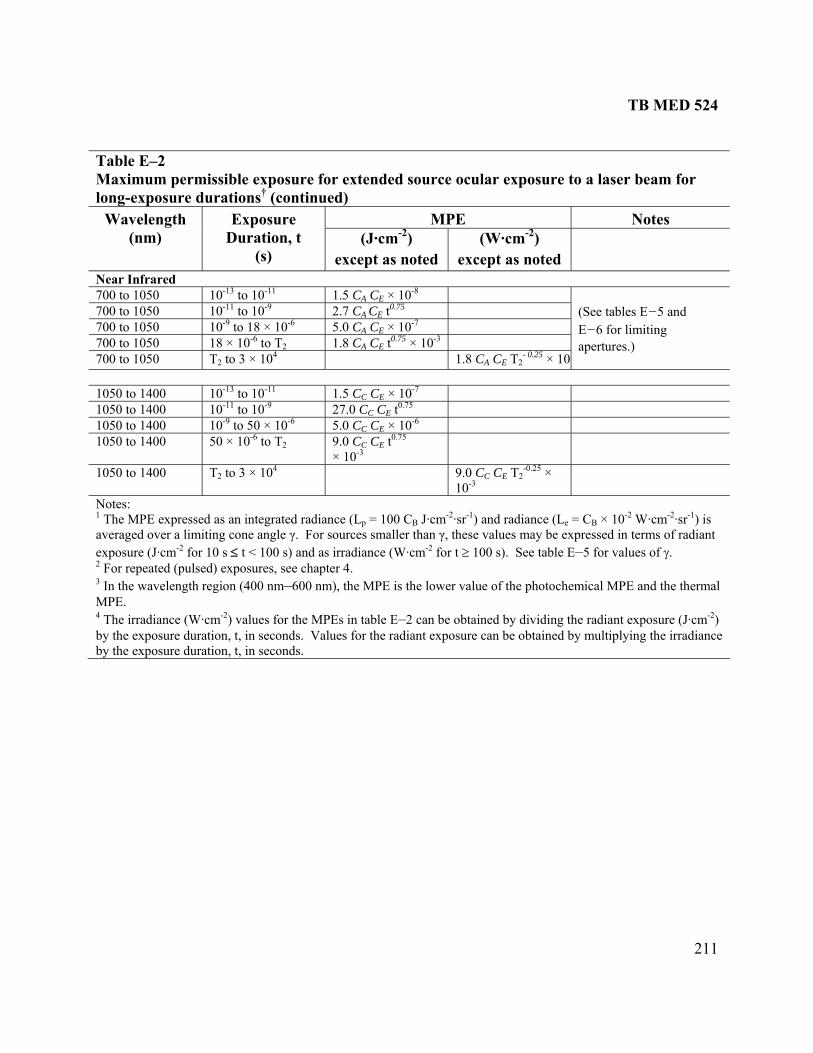
TB MED 524
211
TM for l durations (continued)
able E–2 aximum permissible exposure for extended source ocular exposure to a laser beam
ong-exposure †
MPE Notes W(n Duration,
(s) (J·cm-2
except as noted (W·
except as noted
avelength m)
Exposure t ) cm-2)
Near Infrared 7 10- 1.5 CA CE 00 to 1050 13 to 10-11 × 10-8
7 10- 2.7 CA CE t 75 00 to 1050 11 to 10-9 0.
7 10-9 -6 5.0 CA CE 00 to 1050 to 18 × 10 × 10-7
7 18 1.8 CA CE t 75 × 10-3 00 to 1050 × 10-6 to T20.
7 T2 1.8 CA C T2- 0.25 × 1000 to 1050 to 3 × 10⁴
E-
(SE–ap
ee tables E–5 and 6 for limiting
ertures.)
1 10- 1.5 CC CE × 10 050 to 1400 13 to 10-11 -7
1 10- 27.0 CC CE 050 to 1400 11 to 10-9 t0.75
1 10-9 -6 5.0 CC CE 050 to 1400 to 50 × 10 × 10-6
1 50 9.0 CC CE t× 10-3
050 to 1400 × 10 to T-62
0.75
1 9.0 CC CE T2-0.25 ×
-3 050 to 1400 T2 to 3 × 10⁴
10N1
otes: he MPE expressed as n integrated radian T a ce (L = 100 Cp B J·cmB
-2 -1·sr ) and radiance (Le B × 10 = C B
-2 -2 -1
ae2 pter 4. 3 In the wavelength region (400 nm–600 nm), the MPE is the lower value of the photochemical MPE and the thermal MPE. 4 The irradiance (W·cm-2) values for the MPEs in table E–2 can be obtained by dividing the radiant exposure (J·cm-2) by the exposure duration, t, in seconds. Values for the radiant exposure can be obtained by multiplying the irradiance by the exposure duration, t, in seconds.
W·cm ·sr ) is veraged over a limiting cone angle γ. For sources smaller than γ, these values may be expressed in terms of radiant xposure (J·cm-2 for 10 s ≤ t < 100 s) and as irradiance (W·cm-2 for t ≥ 100 s). See table E–5 for values of γ. For repeated (pulsed) exposures, see cha
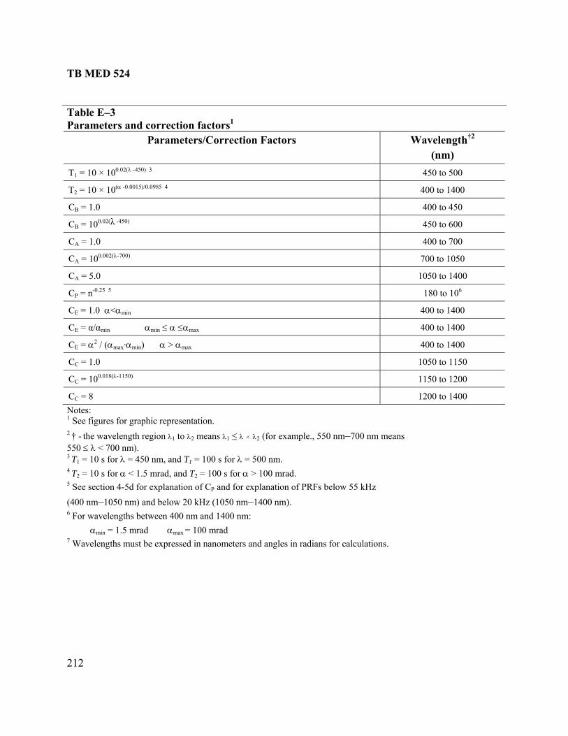
TB MED 524
212
Table E–3 Parameters and correction factors1
Parameters/Correction Factors Wavelength†2 (nm)
T1 = 10 2(λ -450) 3 450 to 500 × 100.0
T2 = 10 × 10(α -0.0015)/0.0985 4 400 to 1400
C = 1.0 BB 400 to 450
CB = 10 λB
-450)0.02( 450 to 600
CA = 1.0 400 to 700
CA = 10 λ-700) 700 to 1050 0.002(
CA = 5.0 1050 to 1400
CP = n-0.25 5 180 to 106
C = 1.0 αE <αmin 400 to 1400
C α/αE = αmax 400 to 1400 min αmin ≤ α ≤
CE = α / (α α2max·αmin) α > 400 to 1400 max
C 1.0 C = 1050 to 1150
CC = 100.018(λ-1150) 1150 to 1200
CC = 8 1200 to 1400 Notes: 1 See figure resentation. s for graphic rep† - t means
00 nm). or λ = 450 nm, a λ = 500 nm r α < 1.5 mrad, and T2 = 100 s for α > 100 mrad. n 4-5d for expla d for explanat ow 55 kHz
0 nm) and belo 050 nm–1400 n
αmin = 1.5 mrad αmax = 100 mrad 7 Wavelengths must be expressed in nanometers and angles in radians for calculations.
2 he wavelength region λ1 to λ2 means λ1 ≤ λ < λ2 (for example., 550 nm–700 nm550 ≤ λ < 73 T = 10 s f nd T = 100 s for . 1 14 T = 10 s fo25 See sectio nation of C an ion of PRFs belP
nm–105 w 20 kHz (1 m). (4006 For wavelengths between 400 nm and 1400 nm:

TB MED 524
213
Table E–4 Maximum permissible exposure for skin exposure to a laser beam
MPE Notes Wavelength Exposure (nm) Duration
(s) , t (J cm-2
as (W cm-2)
)
exceptnoted
except asnoted
Ultraviolet 180 to 302 10-9 to 3 × 10⁴ 3 × 10⁻³
303 10-9 to 3 × 10⁴ 4 × 10⁻³
304 10-9 to 3 × 10⁴ 6 × 10⁻³ 305 10-9 to 3 × 10⁴ 1.0 × 10⁻²
306 10-9 to 3 × 10⁴ 1.6 × 10 -2 307 10 to 3 × 10⁴ 25 × 10-3 -9
308 10-9 to 3 × 10⁴ 40 × 10-3 309 10-9 to 3 × 10⁴ 63 × 10-3
310 10-9 to 3 × 10⁴ 0.1 311 10-9 to 3 × 10⁴ 0.16 312 10 to 3 × 10⁴ 25 -9 0.313 10-9 to 3 × 10 4 0.40 314 10 to 3 × 10⁴ 0.63 -9
315 to 400 10-9 to 10 0.56 t 0.25 315 to 400 10 to 103 1.0 315 to 400 103 to 3 × 10⁴ 1 × 10⁻³
Or 0.56 t0.25 whichever is wer.
.5 mm limiting aperture: See table E–5.)
lo3(
Visible and Near Infrared 400 to 1400 10-9 to 10-7 2 CA x 10 -2
400 to 1400 10-7 to 10 1.1 CA t0.25 400 to 1400 10 to 3 × 10⁴ 0.2 C (See table E–5.)
A
3.5 mm limiting aperture:
Far Infrared 1400 to 1500 10-9 to 10-3 0.1 1400 to 1500 10-3 to 10 0.56 t0.25 1400 to 1500 10 to 3 × 10⁴ 0.1 1500 to 1800 10-9 to 10 1.0 1500 to 1800 10 to 3 × 10⁴ 0.1 1800 to 2600 10-9 to 10-3 0.1 1800 to 2600 10-3 to 10 0.56 t0.25 1800 to 2600 10 to 3 × 10⁴ 0.1 2600 to 106 10-9 to 10-7 1 × 10⁻² 2600 to 106 10-7 to 10 0.56 t0.25 2600 to 106 10 to 3 × 10⁴ 0.1
(See table E–5 for limiting apertures.)
Note: 1 See table E–3 for correction factor CA. 2 The irradiance (W·cm-2) values for the MPEs in table E–4 can be obtained by dividing the radiant exposure (J·cm-2) by the exposure duration, t, in seconds. Values for the radiant exposure can be obtained by multiplying the irradiance by the exposure duration, t, in seconds.

TB MED 524
214
able E–5 ertures (irradiance and radiant exposure) and limiting cone angles γ (radiance
evaluation and accessible emission limit determination
TLimiting apand integrated radiance) for hazard
Spectral R(nm) (s)
Aperture Diegion Duration ameter (mm) Eye Skin
180 to 400 10-9 to 0.3 0.3 to 10 * 10 to 3 x 10⁴
1.0 1.5 t 0.375
3.5
3.5 3.5 3.5
400 to 1400 10-13 to 3 x 10⁴ 7.0 3.5
1400 to 105 10-9 to 0.3
0.3 to 10a 10 to 3 x 10⁴
1.0 1.5 t 0.375
3.5
3.5 3.5 3.5
105 to 106 10-9 to 3 x 10⁴ 11.0 11.0 Limiting Cone Angle, γ (mrad)
400 to 600 0.7 s to 100 100 to 104
104 to 3 × 10⁴
11 1.1 × t0.5
110
Notes: 1 Under normal conditions, these expo2
sure duration would not be used for hazard evaluation. elength region λ1 to λ2 means λ1 ≤ λ < λ2 nm, (for example 315 nm–400 nm means 3 nm). The wav
15 ≤ λ < 400
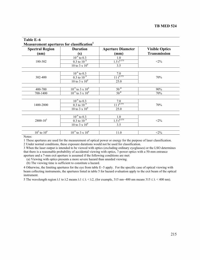
TB MED 524
215
Table E–6 Measurement apertures for classification1
Spectral Region )
tion
Aperture Diameter (mm
Visible Optics Transmission (nm
Dura(s) )
10-9 to 0.3 1.0 0.3 to 10 2 1.5 t0.375
180-302
10 to 3 x 10⁴ 3.5
<2%
10-9 to 0.3 0 7.0.3 to 10 3 1 t0.3751
302-400
to 3 x 10⁴ 5.0
70%
10 2
400-700 to 3 x 10⁴ 4 90% 10-9 50700-1400 10 to 3 x 10⁴ 4 % -9 50 70
10-9 to 0.3 0 7.0.3 to 10 3 1 t0.3751
1400-2800
to 3 x 10⁴ 5.0 10 2
70%
10-9 to 0.3 0 1.0.3 to 10 3 1. t0.3755
2800-105
10 to 3 x 10⁴ 5
<2%
3.
105 to 106 -9 to 3 x 10⁴ <2% 10 11.0 Notes: 1 These apertures are used for the measurement o er or en gy for the purpose
al conditi xposure durati ot be used for classification. ser output be viewed with optics (excludin ry eyeglasse ermines
probability of accidental viewing with optics, 7-power optics with a 50-mm entrance 7-mm ex assumed if th owing conditio s are met: with opti a more severe d iewing. ing time constitute a hazard. e limitin for the eye fro le E–5 apply. For the specific case of optical viewing with
g instrum s listed in table 5 for hazard e ation apply to t
gth regio eans λ1 ≤ λ < xample, 3 nm–400 nm mea 400 nm).
f optical pow er of laser classification.
s) or the LSO det2 Under norm ons, these e ons would n3 When the la is intended to g ordinathat there is a reasonableaperture and a it aperture is e foll n
(a) Viewing cs presents hazard than unaide v(b) The view is sufficient to
4 Otherwise, th g apertures m tabbeam collectin ents, the aperture valu he exit beam of the optical
ns 315 ≤ λ <instrument. 5 The wavelen n λ1 to λ2 m λ2, (for e 15
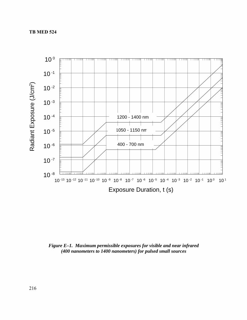
TB MED 524
216
Figure E–1. Maximum permissible exposures for visible and near infrared (400 nanometers to 1400 nanometers) for pulsed small sources
10 -13 10 -12 10 -11 10 -10 10 -9 10 -8 10 -7 10 -6 10 -5 10 -4 10 -3 10 -2 10 -1 10 0 10 1
Exposure Duration, t (s)
10 -8
10 -7
10 -6
-5
-4
10 -3
-2
-1
10
10
10
10
10 0
Rad
iant
Exp
osur
e (J
/cm
2 )
400 - 700 nm
1050 - 1150 nm
1200 - 1400 nm

TB MED 524
217
Figure E–2. Maximum permissible exposures for small and extended source ultraviolet
radiation for exposure durations from 10-9 to 30,000 seconds for ocular exposures and 10-9to 103 seconds for skin exposure
200 240 280 320 360 400
Wavelength (nm)
10
10 -2
10 0
-3
10 -1
10 1
Rad
iant
Exp
osur
e (J
/cm
2 )

TB MED 524
218
Figure E–3. Maximum permissible exposures for ultraviolet (315 nano or single
10 1
IR
1500 - 1800 nm
315 - 400 nm
> 2600 nm
1400 - 1500 & 1800 - 2600 nm
Rad
iant
Exp
osur
e (J
/cm2 )
meters to 400 nanometers) and infrared (1400 nanometers to 1 millimeter) fpulses or continuous exposure to small or extended sources
10 -9 10 -8 10 -7 10 -6 10 -5 10 -4 10 -3 10 -2 10 -1 10 0 10 1 10 2
Exposure Duration, (s)
10 -3
10 -2
10 -1
10 0
UV
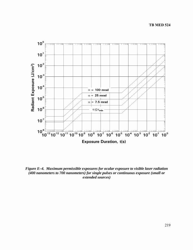
TB MED 524
219
Figure E–4. Maximum permissible exposures for ocular exposure to visible laser radiation (400 nanometers to 700 nanometers) for single pulses or continuous exposure (small or
extended sources)

TB MED 524
220
Figure E–5. S illiradian) for
(Solid lines are nd dashed lines are maximum permissible exposures based on photochemical effects)
mall source ocular maximum permissible exposures (α ≤ 1.5 mvisible and near infrared (400 nanometers to 1400 nanometers)
maximum permissible exposures based on thermal effects, a
10 -1 10 0 10 1 10 2 10 3 10 4
Exposure Duration, t (s)
10 -4
10 -3
10 -2
10 -1
Irrad
ianc
e (W
/cm
1200 - 1400 nm
2 )
1050 - 1150 nm
400 - 700 nm490 nm
400 - 450 nm
475 nm

TB MED 524
221
Figure E-6. Extended source ocular maximum permissible exposures (α = 3 milliradian) for visible and near infrared (400 nanometers to 1400 nanometers)
(Solid lines are maximum permissible exposures based on thermal effects, and dashed lines are maximum permissible exposures based on photochemical effects)
10 -1 10 0 10 1 10 2 10 3 10 4
Exposure Duration, t (s)
10 -4
10 -3
10 -2
10 -1
10 0
Irrad
ianc
e (W
/cm
2 )
400 - 450 nm
475 nm
400 - 700 nm
500 nm
1200 - 1400 nm
1050 - 1150 nm

TB MED 524
222
Figure E–7. E illiradian) for
(Solid lines shed lines are maximum permissible exposures based on photochemical effects)
xtended source ocular maximum permissible exposures (α = 11 mvisible and near infrared (400 nanometers to 1400 nanometers)
are maximum permissible exposures based on thermal effects, and da
10 -1 10 0 10 1 10 2 10 3 10 4
Exposure Duration, t (s)
10 -4
10 -3
10 -2
10 -1
10 0
Irrad
ianc
e (W
/cm
2 )
1200 - 1400 nm
1050 - 1150 nm
400 - 450 nm
475 nm
400 - 700 nm
514.5 nm
500 nm
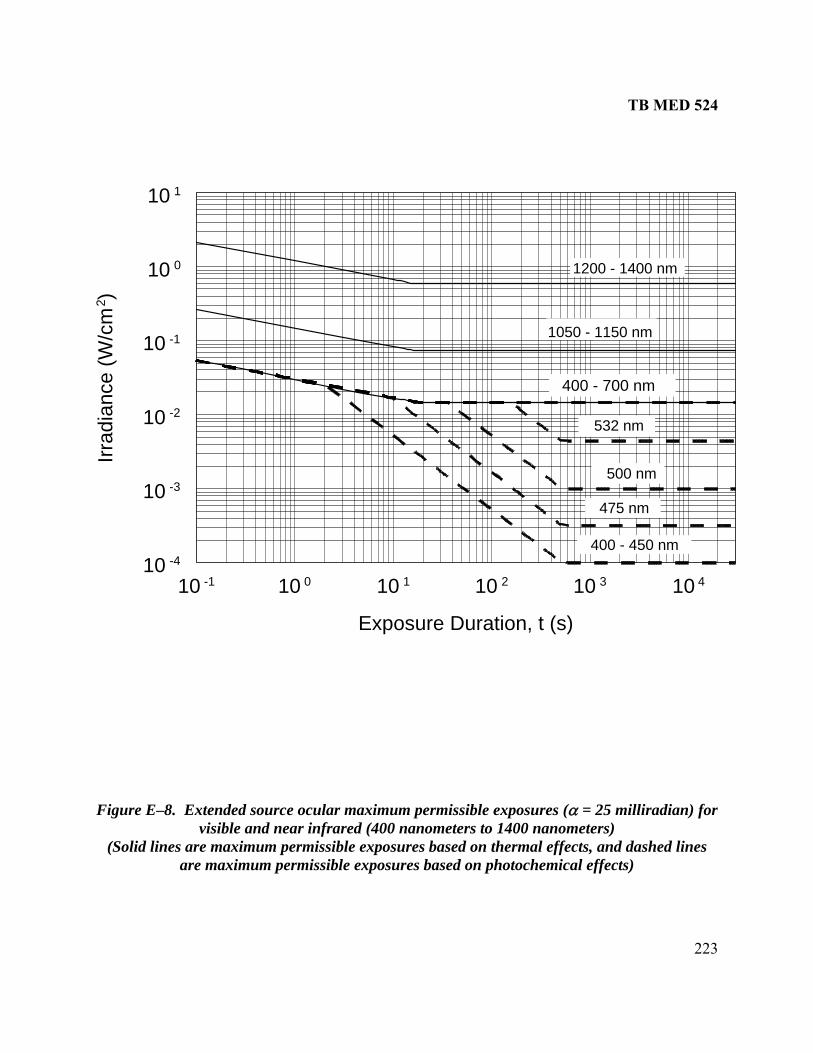
TB MED 524
223
F
igure E–8. Extended source ocular maximum permissible exposures (α = 25 milliradian) for visible and near infrared (400 nanometers to 1400 nanometers)
(Solid lines shed lines are maximum permissible exposures based on thermal effects, and daare maximum permissible exposures based on photochemical effects)
10 -1 10 0 10 1 10 2 10 3 10 4
Exposure Duration, t (s)
10 -4
10 -3
10 -2
10 -1
10 0
10 1
1200 - 1400 nm
Irrad
ianc
e (W
/cm
2 )
1050 - 1150 nm
400 - 450 nm
475 nm
400 - 700 nm
532 nm
500 nm

TB MED 524
224
Figure E–9. Extended source ocular maximum permissible exposures (α = 50 milliradian) for
(Solid lines ar dashed lines
visible and near infrared (400 nanometers to 1400 nanometers) e maximum permissible exposures based on thermal effects, and
are maximum permissible exposures based on photochemical effects)
10 -1 10 0 10 1 10 2 10 3 10 4
Exposure Duration, t (s)
10 -4
10 -3
10 -2
10 -1
10 0
10 1
Irrad
ianc
e (W
/cm
2 )
400 - 700 nm
1200 - 1400 nm
1050 - 1150 nm
550 nm
532 nm
500 nm
400 - 450 nm
475 nm
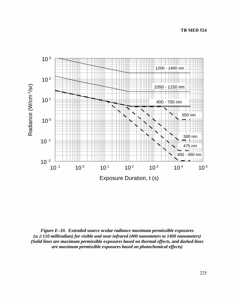
TB MED 524
225
Figure E–10. Extended source ocular radiance maximum permissible exposures (α ≥ 110 milliradian) for visible and near infrared (400 nanometers to 1400 nanometers)
(Solid lines are maximum permissible exposures based on thermal effects, and dashed lines are maximum permissible exposures based on photochemical effects)
10 -1 10 0 10 1 10 2 10 3 10 4 10 5
Exposure Duration, t (s)
10 -2
10 -1
10 0
10 1
10 2
10 3
Rad
ianc
e
1200 - 1400 nm
(W/c
m2 /s
r) 1050 - 1150 nm
400 - 450 nm
475 nm
400 - 700 nm
550 nm
500 nm

TB MED 524
226
Figure E posures
10 -4
10 -3
10 -2
10 -1
10 0
10 1
10 2
Inte
grat
ed R
adia
nce
(J/c
m2 /s
r)
1200 - 1400 nm
1050 - 1150 nm
400 - 700 nm
10 -12 10 -9 10 -6 10 -3 10 0
Exposure Duration, t (s)
–11. Extended source ocular radiance maximum permissible ex(α ≥ 100 milliradian) for visible and near infrared (400 nanometers to 1400 nanometers) for
pulsed or continuous wave exposures less than 1 second

TB MED 524
227
APPENDIX F
CONTROL MEASURES
F–1. Introduction This appendix contains control measures, administrative, procedural, and engineering to reduce the possibility of exposure of the eye and skin to hazardous levels of laser radiation and other hazards associated with laser devices during operation and maintenance. F–2. Scope The LSO/RSO or, when appropriate, the Range Control Officer have the authority to monitor and enforce the control of laser hazards. They can also provide guidance for protecting individuals from a laser systems hazard and the proper control measures to enforce during laser operations.

TB MED 524
228
Table F–1 Administrative and procedural control measures for all laser classes
Laser Classification Administrative & Procedural Control Measures 1 1M 2 2M 3a (3R) 3b (3B) 4
Laser Operator/Maintenance Manual X1 X X X X X X Standard Operating Procedures ---2 --- --- --- --- X X Laser Output Limits --- --- --- --- RSO Determination Education and Training --- •3 • • • X X Authorized Personnel --- --- --- --- --- X X Beam Alignment Procedures --- • X X X X X Spectators Not Permitted in Laser Controlled Area
--- --- --- --- --- • X
Service Personnel 4
MPE
MPE
MPE
MPE
MPE X X
Laser Optical Fiber Systems MPE5 MPE MPE MPE MPE X X Laser Robotic Installations --- --- --- --- --- X
NHZ6X
NHZ Eye Protection --- *7
MPE --- *
MPE --- •
MPE X
MPE Protective Windows --- --- --- --- --- X
MPE X
NHZ Protective Barriers and Curtains --- --- --- --- --- • • Skin Protection --- --- --- --- --- X
MPE X
NHZ Other Protective Equipment Use may be required Warning Signs and Labels (Design Requirements)
• • • • • X NHZ
X NHZ
Service and Repairs RSO Determination Modifications and Laser Systems RSO Determination Notes: 1 X–Shall 2 ---–No Requirement 3 •–Should 4 –Shall, if enclosed Class 3b or Class 4 5 MPE–Shall, if MPE is exceeded 6 NHZ–nominal hazard zone analysis required 7 *–Applicable only if optics are present

TB MED 524
229
Table F–2 Engineering control measures
for all laser classes Laser Classification Engineering
Control Measures 1 1M 2 2M 3a (3R)
3b (3B)
4
Laser Protective Cover X1 X X X X X X Without Laser Protective Cover RSO Shall Establish Alternative Controls Interlocks on Protective Cover 2 X X Service Access Panel X X Key Control ---3 --- --- --- --- •4 X Exit Port Cover (chapter 9–6e) --- --- --- --- --- X X Remote Control(chapter 9–6f)
Interlock Connector --- --- --- --- --- X X
Activation Warning System --- --- --- --- X†5 X X Emission Indicator (chapter 9–6h) --- --- --- --- X X X Identification Label chapter (9–5a) X X X X X X X Hazard Warning Label (chapter 9–5k
•6 •6 X X X X X (1))
FDA Certification Label or Exemption Label
X X X X X X X
Laser Exit Port Label (chapter 9–k(2))
•7 •6 X X X X X
Interlock Label (chapter 9–5k(3)) X8 X8 X8 X8 X8 --- --- Laser Area (Range) Warning Signs (chapter 5–4)
--- • --- • • X NHZ9
X NHZ
Optical Sights (chapter 9–5 i) --- MPE10 MPE MPE MPE MPE MPE Optical Ports (chapter 9–5 h) --- MPE MPE MPE MPE MPE MPE Weight-on-Wheels Interlock (Airborne Systems Only) (chapter 9–6 j)
--- --- --- --- --- X X
Open Beam Path --- --- --- --- --- X NHZ
X NHZ
Indoor Laser Controlled Area (chapter 5–3)
--- MPE --- --- • X NHZ
X NHZ
Laser Outdoor Range Controls (chapter 6)
--- MPE • • • X NHZ
X NHZ
Notes: 1 X–Shall 2 –Shall if enclosed Class 3b or Class 4 3 ---–No requirement 4 •–Should 5 †–If laser can emit more than 25 times the Class 1 AEL 6 Label to simply identify laser as Class 1 or Class 1 M 7 Lasers operating at invisible wavelengths only 8 Defeated interlock allows access to Class 3B or Class 4 emission levels 9 NHZ–nominal hazard zone analysis required 10 MPE–Shall, if MPE is exceeded

TB MED 524
230
This page inte ally ft bla
ntion le nk

TB MED 524
231
APPENDIX G
TEYE PROTEC ION
d at limitin e lase xposure, thereby, reducing the risk of injury. e devices should on e us hen inee and inistrative controls
he hazard. pro ion is en a essary contro easure.
ents f laser stemsnformation on OD requiremen r dif ent l syste . Table –1
ting eye tecti Tech l inf ation on commercially es is av ble f USA RP bsite
pgea.army.mil/las links/ ks.htm
G–1. Control measures Control measures are aime g th r eLaser eye protectiv ly b ed w eng ring admdo not adequately control t Eye tect oft nec l m G–2. Optical density requirem or sy This appendix provides i ts fo fer aser ms Gprovides information on selec pro on. nica ormavailable laser protective devic aila rom CHPPM LO we at:http://chppm-www.a er/ lin l. Table G–1 Simplified method for selecting laser eye protection for small source viewing (wavelengths
d 1400 n omet ) between 400 nanometers an an ersQ-Switched Non-Q-S
Laser (0.4 x 10
(10-9–10-2 s) 10
witcheLaser
-3–
Co inuouW asM nta(0 –10 s
Continuous-e L g-T
tarti(< 1 hr)
d
-2 s)
nt s-ave L ers ome ry .25 )
Wav asersLon erm
S ng
Attenuation
Maximum MaxOutput BeaEnergy
m
Radiant
·cm )
Max Laser
Output gy
(J)
Max Beam
Radiant Exposu(J·cm-2)
Max PowOutput
(W
Max Bea
Irradiance (J·cm
Max Power Output
(
Max m
Irradiance (J -2)
Attenuation Factor
OD
(J) Exposure -2
Ener(J
re
er
)
m
-2) W)
Bea
·cm
10 20 100 200 1 2 x 1 1 0 108 8 05 05 00 201 2 10 20 10 2 x 10 10 20 107 7 4 4
10-1 2 x 10⁻¹ 1 2 103 2 x 10³ 1 2 106 6 10-2 2 x 10⁻² 10-1 2 x 10⁻¹ 100 200 10-1 2 x 10⁻¹ 105 5 10 2 x 10⁻³ -3 10-2 2 x 10⁻² 10 20 10-2 2 x 10⁻² 104 4 10 2 x 10⁻⁴ -4 10-3 2 x 10⁻³ 1 2 10-3 2 x 10⁻³ 103 3 10-5 2 x 10⁻⁵ 10-4 2 x 10⁻⁴ 10-1 2 x 10⁻¹ 10-4 2 x 10⁻⁴ 100 2 1 2 x 10 10 2 x 10 100-6 -6 -5 -5 -2 2 x 10⁻² 10-5 2 x 10⁻⁵ 10 1
Note: See table H 1 for a listing of currently fielded la– ser systems and the OD required to provide adequate protection for their safe use.

TB MED 524
232
This page intentionally left blank

TB MED 524
233
SPECIFIC LASER SYSTEMS
APPENDIX H
H–1. Introduction This appendix provides descriptions and safety information for currently fielded laser fire controsystems. Fire control laser systems are laser rangefinders and laser designators, which in most cases are eye hazards that require eye protection for downrange viewing of the direct beam.
l
FM 8–50
(1) AC–130U, Laser Target Designator/Rangefinder (LTD/RF). This is mounted on the AC–30U aircraft.
, Night Targeting System. This is a modification to the Marine Corps AH-1
em with camera and video tracker. ( nfrar –1 infrar ng las850 n ength) for us VGs. T aser is mounted on Marine Corps XM-218, 50 caliber, M–60 an Uni e gun mounts. The AIM n is hard n the A IM–1/ M–1/MLR, AIM r e Arm licopter or used separately or
n rifles VIS s pr ade prot hes AEYES NVGs do not protect against laser radiation. ES se Ai ry s r unnery Training Sys (PG O D ssi The ms are an extension of and are similar to the MILES. The AG D, S and PGTS systems infrar ser bea to sim te vario air def , airbo , and g nd w s sys s to improve realism during tra g. T – is a simu tor of rget d by a laser; it consistsinf d las er c ed by ser. Table H sts ca nary g dist for aney pose ith e infrared laser beam for vLATAGS a S, a N/G imu ese systems are pointed t rd the sky, aimed at a retroreflector mounted on a target in a restricted area, or contained within a
zar
Altitude Navigation and Targeting Infrared for Night (LANTIRN). ANTIRN is a two-pod system containing a terrain following radar, FLIR, LD, and in
newer models, a target recognition system. Originally it was designed for the H–15E and H–16, and the targeting pod is now integrated with some U.S. Navy F–14s.
H–2. Fielded laser systems The laser systems identified in this document have been evaluated and approved by the DOD Laser System Safety Review Board. a. Description. The following is a listing of fielded laser systems as identified in and MIL–STD–828A: 1 (2) AH–1WTelescopic Sight Unit to include night targeting capability through the direct view optics using a Forward Looking Infrared (FLIR) and LD/LRF syst
3) Advanced Im wavel
ed Module–1 (AIMe with N
). A Class 3b he AIM/Mini L
ed diode, aimi Range (MLR)t–17B machinD
er (830 nm–
d Aircraft Gun/EXL versio–1/EXL devices are integ
m oountedated into th
H–1 turret. Ay AH–1F he
, AIM–1/DLR, AI
mounted o
(4) AG
army
/AD, LaTS) for T
. AN
r Air toW and
NVG
r Gunneragon mi
ovide
System
quate
(LATAGS
ection
), and P
against t
ecision G
e lasers. C T'S
tem L G
les. se systeES/A ATA emit ed la ms
ula us ense rne rou eapon teminin he AN/GVT 1 la a ta illuminate of an rare er emitt over a diffu –2 li utio viewin ance e ex d from w in th arious versions of the AGES/AD,
nd PGT nd A VT–1 s lators. Since th owa
diffuser, no optical radiation hazard exists during normal field exercises. Other potential hasuch as posed by the blast simulators must be considered. (5) AN/AAQ–14, Low-
ds
L

TB MED 524
234
(6) AN/AAQ–22, Navigational Thermal Imaging System. Turret mounted FLIR/LRF on the tility Helicopter (UH)–1N helicopter.
AN/AAS–33A, Target Rec System. This system is ounted on the A6–E Aircraft and has a LD and FLIR.
(8) AN/AAS–37. LRF/LD mounted on the Marine Corps OV-10 Observation Aircraft. (9) AN/AAS–38A, Nite Hawk. Pod mounted on lower left side of F/A–18 aircraft contains a FLIR and LD/LRF. (10) AN/ALQ–212, Advanced Tactical Infrared Countermeasures System. Laser countermeasure system employed in several Army helicopter systems. (11) AN/GAQ–T1, Laser Designator Simulator System. (12) AN/GVS–5, Handheld Laser Rangefinder. Infrared Observation Set. (13) AN/PAQ–1, LTD. This is a lightweight, hand-held, battery-operated laser device. Forward observers use the LD to designate targets. (14) AN/PAQ–3, Modular Universal Laser Equipment (MULE). This is a Marine Corps laser designator used with laser energy homing munitions. The MULE is man portable, handheld, or tripod mounted and is used only in a dismounted mode. (15) AN/PAQ–4, AN/PAQ–4A, Pulsed AN/PAQ–4B and AN/PAQ–4C, Infrared Aiming Light. These are Class 1 military exempt laser systems using an 830 nm wavelength laser diode. (16) AN/PED–1, Lightweight Laser Designator Rangefinder. Modular, man-portable target observation and location determining system that has data/image export and laser designation capability. (17) AN/PEQ–1, Special Operating Forces Laser Target Marker (SOFLAM). A man-portable LD used to mark targets for laser-guided ordnance and a laser rangefinder for determining the distance to a target. (18) AN/PEQ–2A, Infrared Target Pointer and Illuminator and Aiming Laser (ITPIAL). A battery-operated, diode laser for small arms. (19) AN/PVS–6, Mini-Eyesafe Laser Infrared Observation Set (MELIOS). Developed for infantry forward observers to measure distance. MELIOS is a Class 3a laser. (20) AN/TVQ–2, G/VLLD. The G/VLLD is the principal ranging and laser-designating device used by Army artillery forward observers with laser energy homing munitions. The G/VLLD is capable of designating stationary or moving vehicular targets and may be used in a stationary, vehicle mounted, or tripod supported dismounted mode. The primary vehicle mount is the Fire Support Team Vehicle. (21) AN/VVG–1. Ruby LRF mounted on the M55lAl Sheridan Vehicles. (22) AN/VVG–2. Ruby LRF mounted on the M60A3 tank. It may be used with two filters, the green Eye-Safe Simulated Laser Rangefinder (ESSLR) filter and the red ESSLR filter. The green ESSLR is eye safe; the red ESSLR is less hazardous than the system without filters but not eye safe. (23) AN/VVG–3. Nd:YAG LRF on the M1 tank and Light Armored Vehicle (LAV)– 105. An eye safe filter is available. (24) AN/VVS–1. Ruby LRF mounted on the M60A2 tank. (25) Avenger. Avenger air defense system, turret mounted LRF on a HMMWV.
U (7) m
ognition Attack Multi-sensor Laser
TB MED 524
235
(26) Compact Laser Designator (CLD ight LD and/or LRF used by the Navy. (27) Fire Arms Training Sy Skills Trainers are a group of weapons simulators produ iple weapons configurations to simulate a variety of weapons and conditions. (28) Fire Support Sensor System (FS3). The FS3 is an integration of Long Range Advanced
and the Laser Designator Module (LDM) from the Lightweight Laser
ees to 0.03 degrees (approximately 500 mrad–0.5 mrad). A built-
od
he ic
). A small, lightwe
stems (FATS). The FATS Engagement ced by several corporations having mult
Scout Sensor SystemDesignator Rangefinder (LLDR). The FS3 provides long range target acquisition, rangefinding, and designation capabilities to armor and infantry fire support teams. (29) GCP–1. A COTS, small, lightweight, infrared aiming laser for use with night vision evices in target identification and night illumination. GCP–1 operates at a power of 30 mWd
with zoom beam from 30 degrin sensor prevents operation in daylight; however, it does not sufficiently reduce power in darkconditions to prevent hazardous illumination of unprotected personnel within the NOHD. TheGCP s at 50 mW and does not inco–1A operate rporate the sensor. (30) Gun Laying and Positioning System (GLPS). A Class 1 laser system, the GLPS is a tripmounted gyroscope compass, electronic digital optical the odolite with an integrated laser rangefinder. (31) Havis Shield M16 Aiming Laser Light Assembly. Designed to be used in conjunction with NVGs on DOD-controlled land. (32) High-Energy Laser Ordnance Negation System (HLONS). High-energy laser used to remotely destroy unexploded ordnance. (33) Indoor Simulated Marksmanship Trainer (ISMT) and Infantry Squad Trainer (IST). Devices use Class 1 lasers (780 nm) in modified weapons to trace the aim point and calculate the location of simulated shots hitting a display screen. These lasers are commercially sold and registered with the FDA. (34) Infrared Zoom Laser Illuminator/Designator IZLID™. A small, handheld device for use at night. (IZLID is a trademark of B. E. Myers & Co., Inc., Redmond, Washington). (35) Javelin Field Tactical Trainer (FTT). A man-portable training system for the shoulder fired Javelin antitank tactical weapon system. The FTT is similar in appearance to the actual Javelin without the explosive parts. The FTT is a key-controlled trainer used during force-on-force training, gunner range qualification, and verification of operating skills in developing Javelin gunners. The FTT consists of the simulated round (SR) and an instructor station that monitors and records the functions of the SR. The SR includes a laser for simulation of target hits with a MILES compatible laser/detector system for scoring hits. (36) Laser Augmented Airborne TOW (LAAT) mounted in the AH–1F COBRA Helicopter: TLAAT system consists of an LRF and receiver that is incorporated into the M65 TOW telescopsight unit. (37) Light-Armored Vehicle (LAV)–105: LAV–105 mm gun LRF. (38) LAV–Air Defense. A turret-mounted carbon dioxide LRF. (39) Long Range Laser Pointer and Illuminator (LPL)–30: A COTS Class 3b long range, infrared diode, aiming laser pointer and illuminator used by command to mark targets of choice to attacking forces equipped with the NVGs.

TB MED 524
236
n-tions. The host vehicle is the HMMWV.
sed of a mobile Command, Control, and bined
and combat simulation during Force-on-Force engagements. es thermal
ht optics. nd-held Nd:YAG LRF. The Radio
large buffer zones.
e MILES is an ingenious system for scoring
owever, the beam is quite concentrated
LES
s to be a Class 1 device. A person would be more likely to receive an eye injury from
3a.
F used to give range data for high-priority targets
.S. Marine
ator for IR Camera. Approved only for use with output power below 30
e Spike (AN/AVQ-12). A TV video tracker/laser target designator pod, used on F–4
unitions. It wasn't much bigger than the missile it excluded. ntaining, stabilized turret with
(40) LRAS3. The LRAS3 is a long range reconnaissance and surveillance system in both maportable and vehicle-mounted configura (41) M55: Helium–neon laser yank gunnery trainer. (42) Mobile Automated Instrumentation Suite. CompriCommunications Center and five categories of player units and capable of supporting comarms testing or training in real-time. The instrumentation suite is capable of data collection, test/exercise control, (43) Mast-Mounted Sight (MMS) on the OH–58D Scout Helicopter: It incorporatand optical sensors and a LRF/LD. It does not have direct-view daylig (44) Mini-Laser Rangefinder (MLRF). A lightweight, haCorporation of America MLRF has off-axis radiation that requires the use ofIt is given the designation of AN/PVS–X to distinguish it from future MLRFs. (45) MILES: Uses Class 1 and Class 3a lasers. Thtactical exercises, dating from the early 1980s. This is accomplished through an infrared beam emitted from each weapon and detected by a target that can be a man or vehicle. These systems do not present a hazard during normal field exercises. Hupon leaving the transmitter and cautionary measures are advised at extremely close engagementranges. Currently, MILES transmitters exist and are used from the original MILES, the MIII, and the MILES 2000. MILES transmitters used for the M16 before 1986 were Class 3a devices as are the MILES 2000 M16 laser transmitters. In 1986, the original MILES (SAT waredesigned the impact of the blank fired at close range than from the infrared energy from the SAT. The MILES II, M16 rifle simulator is also a Class 1 device, but the other MILES II machine gun simulators are Class (46) Navy Mast-Mounted Sight (NMMS). The NMMS is mounted above deck for televisionand IR imaging and incorporates a Class 1 LRsuch as mines, ships, and small watercraft. (47) Nite Eagle: FLIR/LD/LRF. Turret adapted from the Aquilla system for the UCorps UH–1N helicopters. In training and field-testing, laser firing is prohibited when the laser in flight is less than 1000 m from the target. This is required to prevent loss of track and possibility of the beam wandering off the target during slew and reorientation of the laser as thesystem passes over the target. (48) Nite Eye: IlluminmW. (49) Pave Penny (AN/AAS–35). Laser tracker used on the A–10 and A–7 aircraft. It does not contain a laser. (50) Pave Spectre (AN/AVQ–19). Laser tracker and LD used on C-130 gun ships. (51) Pavand F–111 aircraft. It was normally loaded on the left forward AIM–7 missile station, thus, saving a wing station for m (52) Pave Tack (AN/AVQ–26). Advanced optronics, pod coFLIR, LD and tracker used on the F–4, RF–4, and F–111F aircraft.

TB MED 524
237
n Gunnery Simulation System/Precision Gunnery System (TWGSS/PGS) transmitter.
uses r
ss for U.S. forces. TLOS also
nd ield capability.
MS simulators, and the Hellfire Ground Support Simulator (all or
50-caliber gun and rocket simulators and on the lator.
laser wavelength; otherwise, the eye protection will offer the user little
(53) Schwartz Electro-Optic Controller Gun. The controller gun is used with the Tank WeapoThe controller gun can simulate the kill codes of various MILES weapon simulators and reactivate troops or weapons systems during training exercises. This is a Class 1 device and does not present a laser hazard. (54) Shillelagh Conduct of Fire Trainer (SCOFT). IR laser simulator for training on the Shillelagh-Guided Missile System. (55) Target Acquisition and Designation System with Pilot Night Vision Sight (TADS/PNVS). Mounted in the Apache Advanced Attack Helicopter. (56) Target Designator (TD)–100: A day/night-aiming laser. For daytime use this device a Class 2 helium neon visible laser and for nighttime the TD–100 uses a Class 3b infrared lasediode. (57) Target Location and Observation System (TLOS). The TLOS allows the individual soldier to find threat optical and electro-optical surveillance devices located on tanks, scouts, snipers, etc. Location of these devices will enhance the effectivenehas capability to provide covert illumination for fire direction, improved night vision sighting and landing-zone marking. TLOS will also include range finding, precise target location, adigital battlef (58) TWGSS/PGS. The TWGSS/PGS, with modified telescope, has a MILES type transmitter (SAAB version). The TADs, (Mof which use a 1540-nm erbium laser and 904-nm laser diode) comprise the AGES II simulatsystem. AGES II is used on the KIOWAwirestrike modification to the APACHE, which includes a 20 mm area weapon system simu b. Eye protection requirements. Tables H–1 through H–6 are a summary of the eye protection OD requirements for both unaided and optically aided viewing of the direct laser beam. The ODs given must be at the or no protection at the laser wavelength. Table H–7 provides information concerning cautionary eye exposure distances to simulators and training devices.

TB MED 524
238
ation, and er systems
Table H–1 Nominal ocular hazard distance (atmospheric attenuated), range safety informeye protection requirements for vehicle-mounted las
Device/Mounting NOHD NOHD–M Buffer Zone (Buffer Angle)
each side
Safety Filters
Required Eye Protection
built-in1 unaidedwave- length
multi- pulse
single pulse
7x50 binoc
8-cm optics
12-cm
optics
static movingor
clip-on
OD
aidedOD
sipu
OD
ngle lse
OD
nm kilometers kilometers milliradians AN/VVG–1
2694.3 9 32 47 67 2 not Clip-on 5.8 5.8
(M551A1) allowed 5 AN/VVS–1 (M60A2)2
694.3 9 32 36 44 5 10 Clip-on 5
5.8 5.8
AN/VVG–2 (M60A3)2
694.3 8 30 40 47 2 5 Clip-on 5
5.8 5.8
red ESSLR 694.3 0.3 1.8 2 5 green ESSLR
694.3 0 0 0 0 N/A 5
AN/VVG–3 (M1)
7 25 35 44 2 5 5 4.7 4.7
AN/VVG–3 (LAV-105)
8.2 32 41 50 2 5 5 4.7 4.7
ESSLR 0 0 0 0 N/A N/A AVENGER 0(HMMWV)
0 0 0 0 N/A N/A 0 0
AD LRF (LAV) 10600 0 0 0 0 0 N/A N/A 4.0 4.7 FS3 Rangefinder Designator
1540 1064
0 25
0 16
0 64/48
0 5.5
0 5.5
0
5.5 HLONS 1060 22 22 153 --- --- 2 N/A Built-in 5.3 5.3
5 Notes: 1 Assume the built-in safety filter only protects against the wavelength of the laser in which it is installed and that it does not always protect against other laser wavelengths. 2 Target must be 10 m away from the tank to avoid diffuse reflection hazard.

TB MED 524
239
, and
Table H–2 Nominal ocular hazard distance (atmospheric attenuated), range safety informationeye protection requirements for man-transportable laser systems
Device/Mounting NOHD NOHD–M Buffer Zone Safety Required Eye n (Buffer
Angle) Filters Protectio
each side wave-
length multi- pulse
single pulse
7x50 binoc
8-cm optics
12-cm
static moving built-in
optics clip-on OD
OD
1 unaided aided singlor OD OD
e pulse
nm kilometers kilometers milliradians AN/GAQ–T1 (LD82LB) LDSS)
1064 12.5 - 38 43 52 5 N/A Yes 4.6 5.5
AN/GVS–5 (Handheld)
1064 2.7 13 21 27 10 N/A 5 3.7 4.4
red filter (19 dB2)
1064 0.29 1.8 1.8 - 10 N/A
yellow filter (29dB)
1064 0.056 0.55 0.55 - 10 N/A
AN/PAQ–1 1064 7 3.5 15 33 43 10 N/A 4 4.2 5.8 AN/PAQ–3 (MULE)
1064
20
12
53
64
78
2
N/A
5 3.9 5.6
(Tripod) Designator–day Designator–night
20 12 53 64 78 5 N/A
Rangefinder–day
1064 12 12
12 12
37 37
47 47
60 60
2 5
N/A
Rangefinder–night
N/A
Rangefinder with 12dB filter
1064 3.3 3.3 16 25 31 2 N/A
AN/PAQ–3 (MULE) (Handheld) Designator–day Designator–night
1064
20 20
12 12
53 53
64 64
78 78
10 15
N/A N/A
5 3.9 5.6
Rangefinder–day Rangefinder–night
1064 12 12
12 12
37 37
47 47
60 60
10 15
N/A N/A
AN/PAQ–4, A,B,C (IR aiming light)
830 0 0 0 0 0 N/A 0 0

TB MED 524
240
table laser systems (c
Table H–2. Nominal ocular hazard distance (atmospheric attenuated), range safety information, and eye protection requirements for man-transpor
ontinued) Device/Mounting NOHD NOHD-M Bu e
h
Filters R
Protection ffer Zon(Buffer Angle)
Eac Side
Safety equired Eye
length pulse pulse binoc optics
optics
static moving b 1
c OD
un OD OD
OD
wave- multi- single 7x50 8-cm 12-cm
uor
lip-on
ilt-in aided aided single pulse
nm k ometers kilo ers liradil met mil ians AN/PED–1 (LLDR) Rangefinder Designator
1570
0 25
0
0 6
0
0
0 5.
1064
16
4/48
5.5
5.5
5AN/PEQ–1 (SOFLAM)
1064 9.6 35 45 54 10 N/A 4.0 5.3 5
AN/PEQ–(ITPIAL
2 )
ator ly
–
0.263 0.211 0.078
0
1.5 0
2.3 0
3.9
10
N/A N/A N/A N/A
2 2.
Aiming light & IlluminIlluminator onAiming lighthigh Aiming light–low
850
1.8
.560
2.8
.880
4.7
1.5 0
10
10 0
.0 0
AN/PVS-6 (MELIOS)
0. 0 0. 71540 0 007 .019 03 0 0 0 0
AN/PVS–X (Micro-Laser Rangefinder)
10 4 16 29 41 90 degrees - 3 Yes 3. 3.6 3 7 7
AN/TVQ(G/VLLD
–2 )
lter
25 17 63 80 87 2 N/A (Tripod) Designator Rangefinder
8
3.1
8
3.1
28.5
15
40
23
65
2
N/A
Rangefinder w/ .5dB yellow
39 2 N/A 8fi
1064
Yes 3.8 5.5
CLD 1064 9.7 38 48 58 10 N/A 5 4.5 5.4 LLTD 1064 7 15 38 42 10 N/A 4.0 4.9 LRAS3 1570 0 0 0 0 0 0 Notes: 1 Assume the built-in safety filter only protects against the wavelength of the laser in which it is installed and that it does not always protect against other laser wavelengths. 2 dB–decibels.

TB MED 524
241
TabNomprot
le H–3. inal ocular hazard distance (atmospheric attenuated), range safety information, and eye ection requirements for aircraft-mounted laser systems De one
Ang side
fety lters
Eye ction
vice/Mounting NOHD NOHD-M Buffer Z(Buffer
eachle)
SaFi
RequiredProte
wave- le
multi- single 7x50 c
8-cm cs
12-cm p
moving built-in1
pOD
unaided aided single pulse OD
ngth pulse pulse bino opti o tics static
ocli
r -o
On
D OD
nm kilometers kilome milliradian ters s Night Targeting Syste
10 4 69 5 Yes 3.5 5.2 m–AH–1W)
64 15 9.2 8 59 5
AN/ATRAM
64 14.6 9 47 58 67 N/A 5 4.6 5.8 3.0 AS-33A (A–6E)
10
AN/A(OV–
106 11 5 6 59 N/ 5 4. 5.6 3.0 AS-37 10D NOS)
4 .2 7.1 4 5 A 6
AN/A38A (
106 17 10 50 63 73 N/ 5 4.3 5.4 3.0 AS-38 & F/A-18A–F)
4 A
AN/AAdvaInfrarCoun
0.016 1.3 1.3 LQ–212 nced Threat
ed termeasures
0.0065 0
AN/APAV(F–4
1064 10 8 N/A 5 4.2 5.6 SQ–153 E SPIKE E)
6. 33 48 58
AN/APAVE K (F–11
1064 16 8.8 48 52 70 N/A 5 4.3 5.8 VQ–25 TAC1F)
F–11 1064 6 65 N/ TBD N/A 4.5 6.0 7 14 7.5 45 5 A LAA(AH- )
1064 5 3.4 15 30 36 5 5 Yes 3.5 4.8 T 1S & F
LAN(F–14combtrainisecon
11540 1064
15
0
.18 4
59 0.32
8
69 0.58 5.44
N/A
0 N/
53
N/A N/A
N/A N/A
4.0
1.1
5.6 1.25
2.0
TIRN /15/16)2
at mode ng mode dary beam4
064
0 .35
9 0
0.35
48 02. 3.
A
5
MMS58D)Multi
064
35 23 56
76
72 98
85
119 5 5
5 5
4.1 5.3 –C (OH– Single pulse -pulse
1
NITEUH–
10 5 65 5 5 4.1 5.2 3.7 Eagle 1N
64 15 11 45 5
Pave 1064 7.1 4.5 29 38 46 N/A 5 N/A 3.7 5.4 Spectre TAD(AH-
1064 26 16 45 68 71 5 5 yes 4.0 5.5 S 64)

TB MED 524
242
TabNom eye prot ements for aircraft-mounted laser systems (continued)
le H–3. inal ocular hazard distance (atmospheric attenuated), range safety information, andection requirDe M on
Ang side
fety lters
Eye ction
vice/Mounting NOHD NOHD– Buffer Z e le)
SaFi(Buffer
each
RequiredProte
wave- le
multi- single 7x50 c
8-cm cs
12-cmp
moving built-in1
pOD
unaided aided single pulse OD
ngth pulse pulse bino opti o static
tics ocli
r -o
On
D OD
nm kilometers kilome milliradian ters s AN/AAQ–22 NaviThermSyste(UH–
10 4 8.6 5 N/A 4.0 4.0 gational
al Imaging m 1N)
64 0.72 6.1 5
AC-1LTDmodeTrain
106480
0
47
120 56
N/A N/A
55
3.2 1.
4.8 2.9
30U /RF Combat ing mode
7
44 9
90 38
11
2
Magi(SH–MH–
532 7 2.6 5 5 5.2 6.7 c LANTIRN 2F/ 53–E)
0.15 1.1 1.
Notes1 Assu lter only protects against the wavelength of the laser in which it is installed and that it does not alw inst other laser wavelengths. 2 For F is p; for the F–14, the OD used is 1.2. 3 Air F d buff is rad f r LA N A IRN genera olicy is at airc assign m buff of mrad.4 Air F to m air aft se n of 1,000 feet. 5 Navy em y a raft lasing.
TabNominal ocular hazard distance mo er tte ted ran fety information, and eye protection requirements for ship-mounted laser systems
: me the built-in safety fiays protect aga–15/16, this ODorce assigneed a minimuorce poli i
er zoneer zone
2 m 5
o
NTIR . Navy F–14 L NT and l p th raft be
cy s prohibits tand
aintainor budd
crirc
paratio
le H–4
(at sph ic a nua ), ge sa
Device/Mounting NOHD NOHD– Buffer one (Buffer Angle)
each side
Safety Filters
Required Eye Protection
M Z
wave- len
multi- p
single pulse
7x50 oc
8-cm tics
12-cm ptic
static moving built-in1 or
clip-oOD
unaidedOD
aided OD
single pulse OD
gth ulse bin op o s n
n k meters kilometers milliradians m iloMMS 1540 0 0 0 0 0 0 0
Note: 1 Assu length of the laser in which it is installed and that it does not alway nst other laser wavelengths.
me the built-in ss protect agai
afety filter only protects against the wave

TB MED 524
243
ansportable laser systems
Table H–5 Nominal ocular hazard distance (atmospheric attenuated), range safety information, and eye protection requirements for commercial-off-the-shelf man-tr 1
Device/Mounting NOHD NOHD-M Buffer Zone (Buffer Angle)
each side
Safety Filters
Required Eye Protection
wave- length
multi- pulse
single pulse
7x50 binoc
8-cm optics
12-cm optics
static moving built-in2
or clip-on
OD
unaidedOD
aided OD
single pulse OD
nm kilometers kilometers milliradians AIM–1/D 8 000-850 .075 0.46 10 10 1.7 1.7 AIM–1/DLR 800-850 0.236 1.56 2.43 3.55 10 10 1.7 1.7 LPL–30 800-850 0.09 0.68 1.1 1.6 10 10 1.7 1.7 M-931 850 0.011 0.16 0.28 0.4 10 10 0.7 0.8 GCP–1/1A GCP–1B
800-850 1. 2. 3. 10
0.09 0.24
0.68 65
1.1 57
1.6 75
10 10
10 1.7 2.2
1.7 2.2
NITE Eye 980 0.09 0.68 1.1 1.6 10 10 1.7 1.7 HAVIS (M16 Aiming li ht) g
850 0 .012 0.1 0.17 0.25 10 10 1.1 1.1
IZLID II 870 1. 2 4 10 10 30.248 63 .55 .28 3.0 .0 TD–100 TD–100A
850 632.8
0.1 10 10 1.1 0.3
1.1 0.3
850 670
1.1 0.6
1.1 0.6
Notes: 1 Warning! This hazard data could chance since DOD has no control over manufacturing of these products. Hazard
this re val of t te of DOD uat ly ch with t nu rer te ve not changed since the date of the last DOD evaluation.
ild-in safety filter only protects against the wavelength of the laser in which it is installed and that it does otect agai er la ave hs.
6 lar ha rd distance (a safe infor ation, nd eye
equir ts f omm rcia -the-shelf aircraft-mounted laser system
characteristics innsure that characteristics ha
2 e bu
table a id as he da the eval ion; periodical eck he ma factu o
Assume thno always prt
nst oth ser w lengt
Table H–Nominal ocu za tmospheric attenuated), range ty m a protection r emen or c e l-off s
Device/Mounting NOHD NO Z( r A
ch sid
S Filters
Eye Pro on
HD-M BufferBuffe
one ngle)
ea e
afety Requiredtecti
wave- length
mu i- pulse
single pulse binoc
8-cm optics
12-cm static moving built-in1 or
clip-on OD
unaidedOD
aided OD
single pulse
lt 7x50 optics
OD
nm kilometers kilometers milliradians AIM–1/MLR 8 0 00-850 .085 0.68 1.1 1.6 5 5 1.7 1.7 AIM–1/EXL 8 0 00-850 .130 0.68 1.1 1.6 5 5 1.7 1.7
No1 Assume the built-in safety filter only protects against the wavelength of the laser in which it is installed and that it does not always protect against other laser wavelengths.
te:

TB MED 524
244
–7 Table HCautionary distances for eye exposure to weapons simulators and laser training devices Device/Simulator Unaided Viewing Optically Aided Viewing
(m)
Binoc(m)
(7 x 50 ulars)
MILES I/II Large Gun Simulators 10 0 MILES I SAT p B re re 1986 lank Fi 0 0 MILES I SAT p Dr 0re 1986 y Fire 7 MILES I SAT post 1986 0 0 MILES 2000 SA 10 40 T MILES 2000 Un l Lase 4iversa r Transmitter 10 0 MILES SWLTU 0 10 M55 Trainer (0.25 s viewing) 0 0 SCOFT 13 160 Schwartz Electro-optic Controller Gun 0 0 AGES/AD TOW 0 10 AGES/AD–Cha 0pparal 0 AGES/AD Vulc 0an 10 AGES/AD 2.75” 0 Rocket 10 AGES/AD 20 m n 0m Gu 10 AGES/AD Stinge 43r 10 8 AN/ASQ–193 LATAGS 0 154 PGTS 0 0 AGES II TADS, MMS and Hellfire Ground Support System
Erbium Laser GaAs Laser 0 260
0 0
AGES II OH58D Kiowa Warrior 50-Caliber Rocket 8
6 22 10
AS
GES II APACHE 30-mm Advanced Warning ystem
10 50
TWGSS/PGS r Gun (Schwartz E–O)
o 0
5 5 Controlle
Javelin FFT 10 0 AN/GVT–1 Simulated Laser Target
0
With Diffuser Without Diffuser
2760
0 5,0001
ISMT/IST 0 0

TB MED 524
245
APPENDIX I
60825–1.1–1998
STANDARDIZATION WITH INTERNATIONAL STANDARDS– RNAT L ELEC CHN M IONINTE IONA TROTE ICAL CO MISS
I–1. Classification guidelines
The cla o and rt in th t emu te thohed i . The AN 3 m has ays strived to ave a dar
t is as clo t pos ible he eral Laser P uct ormance Stan , is the CDRH, the atio al sta d f er is by Intern tional
otechn m n (IE 60 erie There are currently few differenc we e standard the time of the publ on
136.1– , th ised LP d no en p she a fi rule, b t the c ification pplied e r sta ard to m d w the guide nes.
. Federal r Pr ct Pe forma ce Standard and th mer Nati al St ardInstitute
In the pas LPPS and the ANSI standards did not always consider optically ai vie g highly div g beam (for example, from a diode laser or fiber pigtail source). Su hig
was
ical hazards due to individuals
b. The IEC standard now recommends that all lasers of very low risk and "safe under reasonably ble use" be placed into Classes 1 and Class 1M. Under this classification scheme, Class 1 is
rlication by the IE te Cla t has f
been misused in the United States to refer to “eye-safe” laser wavelengths in the middle infrared spectrum and le l th S 6 it o u i wdiscussing las d p tia r h s t c. Due to the aversion response of the eye, Class 2 lasers are safe for mome viewing under all conditions, and Class 2M are safe for mo iewing only without optic aids. he IEC
al C C T 76, al atio fety and La Equip ent) then created a nal z s R” r Re d R irem s). T new class wi main nsi
lasers previously classified in ANSI as Class 3a, CDRH as Class IIIA, and IEC as Class 3B lasers
products with greatly expanded beams or highly diverging
a. ssificati n guidelines controls et fos h is documen la se establis n ANSI Z136.1 SI Z1 6 Com ittee alw h stan d tha se to iden ical as s with t Fed rod Perf dard suedby and intern n ndar or las safety sued the aElectr ical Com issio C 825 s s). b. es bet en th s. At icati of ANSI Zsystem a
2000 e rev F PS ha t be ublionize
d as nal u lass in th evised nd was be har ith IEC li
I–2 Lase odu r n e A ican on and s
a. t, the F ded winof a ergin ch a hly diverging beam could be collected by an eye loupe and rendered more hazardous. This concernnot previously considered in the development of earlier ANSI standards except in ANSI Z136.2. Safety requirements should be increased when there are increased optusing optical aids. However, safety requirements would not have to be increased when the use of ptical aids is not expected. o
foreseea“eye safe” under all viewing conditions and Class 1M are “eye safe” except when viewed with optical aids. The same considerations are made for Class 2 lasers (that is visible wavelength (400 nm–700 nm) emitting lasers), which pose a low risk. (Note: The term “eye safe” in refe ence to
requently laser use and app is used C to conno ss 1. Because his term
not so ly to C ass 1, e AN I Z13 comm tee av ids the se of th s term hen ers an oten l lase azard at this ime.)
ntary mentary v al T
Technic ommittee 76 (IE C Optic Radi n Sa ser mtransitio one, Cla s 3R (“ fo duce equ ent his ll ly co st of
emitting less than 5 mW. At first glance, these changes appear to be extensive. In truth, very few laser products are affected. Only laser

TB MED 524
246
eams are affected. Almost all Class 1 lasers remain Class 1 and almost all Class 2 products (those am diameters) remain Class 2 in the revised system. Virtually, all of the lasers
y classified. However, a lase y diexpanded beam that may have been “over-classified” by the old system can baccording to this updated classification scheme.
hnical Commission EC revision in 2001 were that the same classification ti
group, and the revised classification scheme became more versatile for e controls may differ based upon risk.
lly, common risk concepts are applied for each class, and the revised scheme laser safety classes.
TComparison of classification schemes
bwith small becurrently classified as Class 3a will become Class 3R. There is no requirement to reassess lasers that were previousl r product with a highl verging or greatly
e reclassified
I–3. International Electrotec a. The advantages
eachof the I me base is
now used withinapplication (vertical) standards wher b. Additionabecame easier to teach in
able I–1
Class IEC 60825 (Amend. 2) U.S. FDA/CDRH ANSI Z136.1 (2000) C aser system containing a laser that cannot emit laser radiation at levels that are known to cause eye or
ring normal operation. This does not apply rvice periods requiring access to Class 1 enclosures igher-class lasers.
lass 1 Any laser or lu
1
skin injury dcontaining h
to se
C wn to cause eye or skin damage ng optics are used.
N/A N/A lass 1M2 Not knounless collecti
C N/A Visible las at are not intended for iewing and cannot produce any known eye or skin ury during operation b d on a maximum exposure time of 1000 seconds.
N/A lass 2a3 ers th v
injase
C lasers considered incapable of emitting laser radia at levels that are known to cause ye injury within the time period of the human eye aversion response (0.25 s).
lass 24 Visible tion skin or e
C
llecting optics are used.
N/A N/A lass 2M5 Not known to cause eye or skin damagewithin the aversion response time unless co
CAULasers that do not E for the unaided eye, bu xceed the MPE by no more than 5 ti es with the use of optical viewing s.
TION exceed the MPt em
aid
C
Visible lase hat cannot emit more 5 mW for time periods greater than 0.38 ms.
DLasers that exceed MPE by no more than 5 times, h or without the use of optical viewing aids and includes lasers with non-visible wavelengths that exceed the MPE by no more than 5 times.
lass 3a N/A 6 rs tthan
ANGER thewit
Class 3R7 Replaces Class 3a and has different limits. Up to 5 times the Class 2 limit for visible and 5 times the Class 1 limits for some invisible wavelengths.
N/A N/A

TB MED 524
247
Table I–1 Comparison of classification schemes (continu d)
Class 3 or
eb8 Medium-powered lasers (visible or invisible regions) that present a potential eye hazard for intrabeam (direct)
specular (mirror-like) conditions. Class 3b lasers do not present a diffuse (scatter) hazard or significant skinhazard except for very high-power Class 3b lasers operating at certain wavelength regions.
Class 4 in for both direct (intrabeam) and scatter (d ve potential hazard considerations for fire (ignition) and byproduct emissions from target or process materials.
High-powered lasers (visible or invis potential acute hazard to the eye and skible) considered to present iffused) conditions. Also ha
1 All form2
er Class 1 lasers are still Class 1. er Class 3a or Class 3b lasers that did not present an unaided viewing hazard are now Class 1M.
s 2. 25 s are
ith the exception of some expanded beam lasers that now
Form3 Class 2a lasers are now Class 1 lasers. 4All former Class 2 lasers are still Clas5 Former Class 3a or Class 3b visible lasers that did not present an unaided viewing hazard for less than 0.now Class 2M. 6 Former Class 3a lasers are now Class 3R lasers. 7 The Class 3R designation replaces the Class 3a designation. Class 3a expanded-beam lasers are rare outside military applications and are now Classes 1M and 2M. 8 Most former Class 3b systems are now Class 3B systems ware classified as either Class 1M or Class 2M.

TB MED 524
248
This page intentionally left blank

TB MED 524
249
GLOSSARY
Section I Acronyms
Air to Ground Engagement System/Air Defense AIM Advanced Infrared Module ANSI American National Standards Institute AN/VVG Army/Navy/Ground Vehicular Visible Light AR Army Regulation BLPS Ballistic and laser protection spectacles CDRH Center for Devices and Radiological Health CFR Code of Federal Regulation CLD Compact Laser Designator
ACGIH American Conference of Governmental Industrial Hygienists AED automated external defibrillator AEL accessible emission limit AGES/AD

TB MED 524
250
cm centimeter(s) cm2
square centimeter(s) COTS commercial off-the-shelf CPR cardiopulmonary resuscitation CW continuous wave DA Department of the Army DA Pam Department of the Army Pamphlet DMSO dimethylsulfoxide DOD Department of Defense DODI Department of Defense Instruction ESSLR Eye Safe Simulated Laser Rangefinder FAA Federal Aviation Administration FATS Fire Arms Training Systems FDA Food and Drug Administration

TB MED 524
251
LIR orward looking infrared
er Product Performance Standard
System
el
S
WV wheeled vehicle
FF FLPPS Federal Las FM Field Manual FS3 Fire Support Sensor System FTT field tactical trainer GCP Ground Commander’s Pointer GLPSGun Laying and Positioning GTL gas transport laser HCLS Healthcare Laser System HCPhealthcare personn HGU head gear unit HIOS high intensity optical source HLONHigh-Energy Laser Ordnance Negation System HMMhigh-mobility multipurpose

TB MED 524
252
echnical Commission
ociety of North America
tion (700 nm–1400 nm)
n (1400 nm–3 µm)
m)
arksmanship Trainer
tor and Aiming Laser
ator
Hz hertz IECInternational Electrot IESNA Illuminating Engineering S IR infrared IR-Anear infrared radia IR-Bmidrange infrared radiatio IR-C far infrared radiation (3 µm–1000 µ ISMT Indoor Simulated M IST Infantry squad trainer ITPIALInfrared Target Pointer and Illumina IZLID Infrared Zoom Laser Illuminator/Design J Joule(s) JP Joint Publication kHz kilohertz

TB MED 524
253
ptically Tracked, Wire (TOW)
TIRN avigation Targeting Infrared for Night
AGS tem
le
contaminants
ator Rangefinder
n Program
vanced Scout Sensor System
km kilometer(s) LAAT Laser Augmented Airborne Tube Launched, O LANLow Altitude N LATLaser Air to Air Gunnery Sys LAV Light Armored Vehic LD Laser designator LDM Laser designator module LGACLaser-generated air LLDR Lightweight Laser Design LORPLaser/Optical Radiatio LRAS3Long Range Ad LRF laser rangefinder LRSNCOLaser Range Safety Noncommissioned Officer LRSO Laser Range Safety Officer
TB MED 524
254
O/LRSNCO Range Safety Officer/Laser Range Safety Noncommissioned Officer
/NCO ed Officer
ety Officer
S Set
S System
IL–HDBK andbook
–STD
(s)
LRSLaser LRSOLaser Range Safety Officer/Noncommission LSDZ laser surface danger zone LSOLaser Saf LSSOLaser System Safety Officer LTD Laser target designator m meter(s) MELIOMini-Eyesafe Laser Infrared Observation MEPMilitary Eye Protection MHz megahertz MILES Multiple Integrated Laser Engagement System MMilitary H MILMilitary Standard mJ milliJoule

TB MED 524
255
sible exposure
facility
mL milliliter(s) MLR Mini-Laser Range MLRF Mini-Laser Rangefinder mm millimeter(s) (1 × 10⁻³ meter(s)) MMS Mast-Mounted Sight MPEmaximum permis mrad milliradian(s) ms millisecond(s) m/s meters per second MSDS Material Safety Data Sheet MSMC Main Support Medical Company MTF Military treatment MULE Modular Universal Laser Equipment mW milliWatt(s)

TB MED 524
256
ssociation
H cupational Safety and Health
red
rd distance-magnifying
k Number
Nd:YAG Neodymium:Yittrium Aluminum Garnet NEC National Electrical Code NFPA National Fire Protection A NG National Guard NHZ nominal hazard zone NIOSNational Institute for Oc NIRnear infra nm nanometer(s) (1 × 10⁻⁹ meter(s)) NMMS Navy Mast-Mounted Sight NMRnuclear magnetic resonance NOHD Nominal ocular hazard distance NOHD–M Nominal ocular haza ns nanosecond(s) NSNNational Stoc

TB MED 524
257
rmal imaging system
em
m2
)
dministration
dulation
eq
re limit
m
ent
x 10-12s)
NTISNavigational the NTS Night targeting syst NVG night vision goggle nW/cnanoWatt per square centimeter(s OD optical density OSHAOccupational Safety and Health A PCM pulse-code mo PDrrequired optical PELpermissible exposu PGS Precision Gunnery System PGTS Precision Gunnery Training Syste PPE personnel protective equipm PRF pulse repetition frequency ps picosecond (1

TB MED 524
258
Officer
T uct of Fire Trainer
LAM arker
e
ylindrical system
AG t
rad radian(s) RF rangefinder RFR radiofrequency radiation RSORadiation Safety s second(s) SAT small-arms transmitter SCOFShillelah Cond SOFSpecial Operations Forces laser m SOP standing operating procedur SPECSspecial protective eyewear, c SPH Sound protective helmet SR Simulated round sr steradian(s) STANstandardization agreemen

TB MED 524
259
/PNVS with Pilot Night Vision Sight
D edical
omagnetic mode
ptically tracked, wire guided
P ation and Readiness Program
SS ulator System
HPPM motion and Preventive Medicine
RD ch Detachment
nm)
SWDGSun, wind, and dust goggles TADSTarget Acquisition and Designation System TB METechnical Bulletin, M TD Target designator TEMtransverse electr TLOS Target Location and Observation System TLV threshold limit value TOWTube launched, o TVCRTri-Service Vision Conserv TWGTank Weapon Gunnery Sim UH Utility helicopter USACU.S. Army Center for Health Pro USAMU.S. Army Medical Resear UVultraviolet (100 nm–400

TB MED 524
260
radiation (315 nm–400 nm)
B diation (280 nm–315 nm)
nm–280 nm)
ty
earch
ion II
orption on of radiant energy to a different form of energy by interaction with matter.
mission limit (AEL) ission level permitted within a particular class.
UV-Aultraviolet UV-ultraviolet ra UV-Cultraviolet radiation (100 UVR Ultraviolet radiation VAvisual acui W Wa(s) WRAIR Walter Reed Army Institute of Res µJ microJoule(s) µm micrometer(s) µs microsecond(s) µW microwatt(s) SectTerms absTransformati accessible eThe maximum accessible em

TB MED 524
261
e radiation le for the human eye or skin to be exposed in normal usage.
nd eye loops, which creases the NOHD by roughly the magnifying power of the optics, ignoring transmission losses
s and atmospheric attenuation. Eye loops should not be included in the hazard finitely being used.
eyond which extended source MPEs for a given exposure duration are expressed s a constant radiance or integrated radiance. This value is defined as 100 mrad.
ee limiting angular subtense.
ight present in the environment around a detecting or interpreting device, generated from outside s. Such light must be treated as noise by the detector.
perture ning or hole through which radiation or matter may pass.
pparent visual angle ubtense of the source as calculated from source size and distance from the eye. It is
ower ivided by the exposure duration.
ion response id or movement of the head to avoid an exposure to a noxious stimulant or bright
ght. In this standard, the aversion response to an exposure from a bright laser source is assumed to 5 s, including the blink reflex time.
eam of rays which may be parallel, divergent, or convergent.
eam attenuator vice designed to decrease flux density or power per unit area of a light beam through
beam.
accessiblRadiation to which it is possib aided viewing Viewing a laser with magnifying optical aids such as binoculars, telescopes, ainthrough the opticcalculations unless they are de αmaxThe angular limit ba αminS ambient light Lsource aAn ope aThe angular snot the beam divergence of the source. average pThe total energy imparted during exposure d aversClosure of the eyellioccur within 0.2 bA collection bA deabsorption and scattering of the

TB MED 524
262
iameter (DL) actly opposed points on a beam at a chosen fraction of peak
ower. e diameter of a circular aperture that will pass a specified percentage (usually 63 percent) of
tween diametrically opposed points in that cross section of beam where the power per unit area is l/e (0.368) times that of the peak power per unit area.
ee divergence.
device which terminates a laser beam path.
ee aversion response.
angle he angle about the laser's line-of-sight with apex at the laser aperture that is used to determine
zone. As a minimum, it is typically set to five times the demonstrated pointing rgence. (Buffer angles for several lasers are assigned
table H–1.)
conical volume centered on the laser's line-of-sight with its apex at the aperture of the laser, in which the beam will be contained with a high degree of certainty. The buffer zone is
he buffer angle.
that increases the MPE values in the near infrared (IR–A) spectral band 00 nm–1400 nm) based upon reduced absorption properties of melanin pigment granules found in
in and in the retinal pigment epithelium.
actor which increases the MPE values in the red end of the visible spectrum –700 nm) due to greatly reduced photochemical hazards.
al bsorption of radiant energy in the spectral region between 1150 nm and 1400 nm.
orrection factor used for calculating the extended source MPE for the eye from the intrabeam PE, when the laser source subtends a visual angle exceeding αmin.
beam d a. Calculated distance between two exp b. Ththe total beam energy. 3. The distance bea beam divergence φ S beam stop A blink reflex S buffer Tthe buffer accuracy of the system plus the beam divein buffer zone Awithdetermined by t CACorrection factor(7the sk CB Correction f(550 nm CC Correction factor which increases the MPE values for ocular exposure because of pre-retina CE CM

TB MED 524
263
tion
uct or any of its components. System indicator
ghts would not normally be considered sources of collateral radiation.
angle one perimeter and its axis.
s wave (CW) pulsed mode. In this standard, a
ser operating with a continuous output for a period of 0.25 s or greater is regarded as a CW laser.
ty of those within is subject to control and supervision for e purpose of protection from radiation hazards.
he transparent outer coat of the human eye, which covers the iris and the crystalline lens. The fracting element of the eye.
rs or in which an electric field can be sustained ith a minimum dispersion of power. They exhibit nonlinear properties such as anisotropy of
tivity or polarization or saturation phenomena.
iffraction ending of a light ray as the light passes through a small hole in a barrier or
ined by the wave nature of radiation and occurring when the diation passes the edge of an opaque obstacle.
CP Correction factor that reduces the MPE for repetitively pulsed exposure of the eye. collateral radiaAny electromagnetic radiation, except laser radiation, emitted by a laser or laser system that is physically necessary for its operation. Extraneous radiation (such as secondary beams from optics, flash lamp light, radiofrequency radiation, x-rays, and so forth) that is not the intendedlaser beam as a result of the operation of the prodli collimated beam Effectively, a "parallel" beam of light with very low divergence or convergence. coneThe acute angle between the c conjunctiva The mucous membrane that lines the inner surface of the eyelids and is continued over the forepart of the eyeball. continuouThe output of a laser that is operated in a continuous rather than ala controlled area An area where the occupancy and activith cornea Tcornea is the main re dielectric Characteristic of materials that are electrical insulatowconduc d a. Refers to the bpasses by the edge of a small barrier. b. Deviation of part of a beam, determra

TB MED 524
264
on.
-ecular reflection from a rough surface). An ideal diffuse surface in which reflected brightness
viewing angle is called a Lambertian surface.
iffuse reflector surface that scatters radiation that is incident on it, thus producing diffuse reflection.
ivergence (φ) e width of the laser beam measured between the two points at which laser radiant
in the laser beam is equal to 1/e (36.8 percent) of the maximum value. ut another way, beam divergence is the increase in the diameter of an initially collimated beam,
beam spread measured in radians or milliradians (1 mrad = 3.4 minutes of arc or
rgy consisting of orthogonally vibrating electric and magnetic fields lying transverse the direction of propagation. X-ray, ultraviolet, visible, infrared, and radio waves occupy various
omagnetic spectrum and differ only in frequency, wavelength, or photon
n enclosed laser with an assigned class number higher than the inherent capability of the laser em in which it is incorporated, where the systems lower classification is appropriate due to the
iameter of the laser beam at the exit aperture of the system in centimeters; for a Gaussian beam, diameter at 1/e peak intensity values.
laser that is contained within a protective housing of itself or of the laser or laser system in which incorporated. Opening or removal of the protective housing provides additional access to laser
gy
diffuser A device used to scatter or disperse light emitted from a source, usually by the process of diffuse transmissi diffuse reflection Reflection from a surface in which the beam is scattered in all directions (for example, a nonspis independent of the dA reflecting dThe full anglexposure or irradiance Por the angle ofapproximately 1 mil). electromagnetic radiation The flow of enetoportions of the electrenergy. embedded laser Asystengineering features limiting accessible emission. emergent beam diameter (a) Dthe enclosed laser Ait is radiation above the applicable MPE than possible with the protective housing in place. (An embedded laser is an example of one type of enclosed laser.) enerThe capacity for doing work. Energy content is commonly used to characterize the output from pulsed lasers and is generally expressed in Joules (J).

TB MED 524
265
helium (of the cornea)
n. Formerly xtended source.
hat radiation composed of the wavelengths falling between light and microwaves, ranging from 1000 µm (IR–C). (See infrared radiation, IR–C.)
ith respect to radiation, a device used to attenuate particular wavelengths or frequencies while nge.
type of laser in which the laser action takes place in a gas medium, usually operated as a CW
beam of light whose electrical field amplitude distribution is gaussian. When such a beam is
epitThe layer of cells forming the outer surface of the cornea. erythema Redness of the skin due to congestion of the capillaries, as in inflammation (that is, sunburn). exposure limit The level of laser radiation to which a person may be exposed without hazardous effect or adverse biological changes in the eye or skin. extended source A source of optical radiation with an angular subtense at the cornea larger than αmie far-infrared radiation Tabout 3 µm to filter Wpassing others with relatively no cha gas laser Alaser. Gaussian Beam Acircular in cross-section, the amplitude is ( ) ( ) ( )[ ]2
wr
0ErE = , where r is the distance from beamcenter and w is the radius at which the amplitude is 1/e of its value on the axis; 2w is the beamiameter.
−
to a laser beam to denote areas within the beam of above average intensity often
d hertz (Hz) The unit that expresses the frequency of a periodic oscillation in cycles per second.
ot spot hTerm appliedattributable to atmospheric inconsistencies. illuminance The measurement of how bright a point source of light appears to the eye. It is measured in foot-andles. c

TB MED 524
266
on to
his region is often divided into three spectral bands by wavelength: IR–A 00 nm–1400 nm), IR–B (1400 nm–3000 nm), and IR–C (3 μm–1000 µm). IR–A is sometimes
d, produces a sensation of heat.
exposure duration. Also nown as pulsed radiance. Unit: Joules per square centimeter per steradian (J-cm-2⋅sr-1).
he phenomenon that results when two or more waves of the same type for example, light waves, sly through the same point(s) and form a combined wave.
er system housings and at the doors of laser facilities where the NHZ xtends to the door and other control measures will not prevent injury to one entering the facility.
is, operating rooms) are exempt from having door interlocks.
ser
b. The viewing condition where the source subtends an angle at the eye that is equal to or less ting angular subtense. This category includes most collimated beams and so
n inventory of all Class 3b (and Class IIIb) lasers and above should be maintained by the LSO. formation on the laser class, type, wavelength, power or energy,
on
he circular pigmented membrane which lies behind the cornea of the human eye. The iris is d by the pupil.
infrared radiatiElectromagnetic radiation, invisible to the human eye, with wavelengths from 700 nanometers 1 millimeter. T(7called near-infrare integrated radiance A synonym for pulsed radiance. The integral of the radiance over the k interference Tpass simultaneou interlock A mechanical device designed to disconnect electrical power to the laser system or to stop the laser beam from exiting the laser housing when the interlock is opened. These are found on Class 3b and Class 4 laseMedical laser facilities (that intrabeam viewing a. With respect to laser radiation, the subjection of the human eye to all or a portion of the labeam. than αmin, the limicalled point sources. inventory AThe inventory should include inlocation, and point of contact. The inventory should be maintained and updated on a regular basis. ionizing radiatiElectromagnetic radiation having a sufficiently large photon energy to directly ionize atomic or molecular systems with a single quantum event. iris Tperforate

TB MED 524
267
t incidence. b. At a point of a surface, the quotient of the radiant power dΦ incident on an element dA of a
taining the point by the area to that element.
unit of radiant exposure used in measuring the amount of energy-per-unit-area of absorbing t area of a laser beam.
unit of energy (1 Joule = 1 Watt second or 0.239 calories used normally in describing a single
n ideal surface whose emitted or reflected radiance is independent of the viewing angle.
or more lasers and where activity of personnel is bject to control and supervision for the protection from radiation hazards associated with laser
yewear sually consists of a set of filters that attenuate specific wavelengths but transmit as much visible
le.
that is as a result of controlled stimulated emission.
arge of laser operations; individual can be either a ilitary person.
idual trained in laser safety that has authority (appointed by the commander) to monitor nd enforce the control of laser hazards and affect the knowledgeable evaluation and control of the
irradiance (power density, E) a. Radiant flux incident per unit area of a surface: radian surface con
⎥⎦⎤
⎢⎣⎡
∂∂
2cmW
AP = E
J·cm-2 or J/cm2
Asurface or per uni Joule Apulsed output of a laser. lambertian surface A laser-controlled area Any location or area where there are onesuoperation. laser eUradiation as possib laser footprint The projection of the laser beam and buffer zone onto the ground or target area. The laser footprint may be part of the laser surface danger zone if the laser footprint lies within the NOHDof the laser. laser radiation All electromagnetic radiation emitted by a laser product in the optical spectral rangeproduced Laser Range Safety Officer/Noncommissioned Officer (LRSO/NCO) Direct representative of the individual in chqualified civilian or m Laser Safety Officer/Radiation Safety Officer (LSO/RSO) An indiva

TB MED 524
268
ith lasers at a particular installation. The term Laser System Safety Officer in
erwork, administration, safety training and ompliance inspections at the installation (for example, Air Force Bio-Environmental Engineer,
ction Officer, Navy Base Safety Officer).
stablishing unit-specific laser regulations and procedures and ensuring compliance to the
ser regulations and restrictions of the host facility that the appropriate operational
d. Installation range laser safety officer. One who has the physical control of the Laser Range onsible for its use; including but not limited to: (1) establishing range specific laser
e
he laser safety program is usually an extension of the Non-Ionizing Radiation Protection f is a component of the overall radiation protection program
urface Danger Zone (LSDZ) or Nominal Hazard Zone (NHZ)
and re required for personnel who may engage in intrabeam viewing within this
rea.
n abnormal change in the structure of an organ or part due to injury or disease.
the purposes of this bulletin, limited to avelengths between 400 nm–700 nm.
pherical mirrors at the ends, that is filled with lasable material. This is any aterial, crystal, glass, liquid, dye or gas, the atoms of which are capable of being excited to a semi-able state by light or an electric discharge. The light emitted by an atom as it drops back to the
hazards associated wthe Navy differentiates the LSSO from the Landing Signal Officer. Each Service's regulations stipulates training requirements for LSOs/LSSOs and may differentiate among⎯ a. Laser safety consultants. Service experts who evaluate and advise on laser safety. b. Base laser safety officer. Responsible for papcArmy Radiation Prote c. Unit laser safety officer. The individual in the laser user's chain of command who is responsible for all laser issues at the operational level. It includes but is not limited to: eappropriate laand safety training for the laser weapon shall be used, maintaining unit laser accountability, andensuring that all other unit related laser safety issues are addressed. and is respsafety regulations and procedures, and (2) ensuring that all users comply with all appropriate laser safety regulations in place at the range. The Range Laser Safety Officer may be from thrange installation or a visiting Unit Laser Safety Officer. Laser Safety Program TProgram, which itsel Laser SThe designated region or ground area where laser radiation levels may exceed the MPE levels,thereby, requiring control during laser operation. Unauthorized personnel are not permitted, laser eye protectors aa laser test set A set of equipment configured to a laser system in order to test the laser’s parameters. lesion A light Visible radiation (400 nm to 700–780 nm). Forw Light amplification by stimulated emission of radiation (Laser) A cavity, with plane or smst

TB MED 524
269
y, excited atoms, the light being thus continually increased in r is made to transmit 1 or 2
gh collimated. With concave mirrors the
beam appears to emerge from a point source near one end of the cavity. limiting aperture (Df) The maximum d ameter of a circle over which irradiance and radiant exposure can be averaged.
limited by the design or intended use(s).
a
tly employed for acute central vision (that is, of best visual acuity).
le exposure (MPE) verse
iological changes in the eye or skin. Laser radiation exposure levels published in ANSI Z136.1 protection of personnel. The MPEs contained in ANSI Z136.1 are used in
unit of length in the international system of units; currently defined as a fixed number of vacuum, of the orange-red line of the spectrum of krypton 86. Typically, the meter
-2 m. b. Millimeter (mm) = 10-3 m.
(μm) = 10-6 m.
μm, micron) ormerly termed micron, a measure of length equal to 10-6 m.
ndth of a radian. One degree equals 17.5 illiradians.
e energy content of each mode internally to give rise cosecond domain.
ground state releases other nearbintensity as it oscillates back and forth between the mirrors. If one mirropercent of the light, a brilliant beam of highly monochromatic, coherent radiation is emitted throuthe mirror. If plane mirrors are used, the beam is highly
i limiting exposure duration (Tmax) An exposure duration which is specifically maculThe small uniquely pigmented specialized area of the retina of the eye, which in normal individuals is predominan maximum permissibThe level of laser radiation to which a person may he exposed without hazardous effect or adband established for thethis handbook and are in concurrence with STANAG 3606. meter Awavelengths, inis subdivided into the following units: a. Centimeter (cm) = 10 c. Micrometer d. Nanometer (nm) = 10-9 m. micrometer (F milliradian (mrad) Unit of angular measure. One mrad equals one thousam mode-locked laser A laser that functions by modulating thselectively to energy bursts of high-peak power and short duration in the pi

TB MED 524
270
the level of the direct, reflected or attered radiation during operation exceeds the applicable MPE. Exposure levels beyond the
below the applicable MPE level.
he distance along the axis of the unobstructed beam from the laser to the human eye beyond which the appropriate MPE;
n axis that forms right angles with a surface or with other lines. The normal is used to determine tive, and refractive angles.
ormal incidence riking a surface at an angle perpendicular to the surface.
cular fundus ck of the eye. May be seen through the pupil with an ophthalmoscope.
he performance of the laser or laser system over the full range of its intended functions (normal
monochromaticity Literally means "one color" or, to be more technically correct, "one wavelength." n Number of pulses. nanometer (nm) Unit of length equal to 10-9 m. Sometimes termed millimicron. near-infrared The shortest wavelengths of the infrared region, nominally 700 nm–1400 nm (IR–A). Neodymium:YAG (Nd:YAG) A cylindrical rod of yttrium-aluminum-garnet doped with neodymium that is the active medium of the Nd:YAG laser, a highly serviceable solid-state device. nominal hazard zone (NHZ) (see also laser surface danger zone) The nominal hazard zone describes the space within which scboundary of the NHZ are nominal ocular hazard distance (NOHD) Tthe irradiance or radiant exposure during operation is not expected to exceed that is, the safe distance from the laser. The NOHD-magnifying is the NOHD when viewing with optical aids. normal Aincident, reflec nLight st oThe ba operation Toperation). It does not include maintenance or service.

TB MED 524
271
s an and Φt is the transmitted
ower at a specific wavelength.
lectromagnetic radiation with wavelengths between 180 nm to 1 millimeter (mm). This spectral regions by wavelength: ultraviolet radiation
nm–1 mm).
ectral range
hotoablation and volatilized by short-pulsed (nanosecond)
s and molecules emit and absorb nergy in single units called "photons." The energy of a single photon is proportional to the
cy of the emitted light wave.
semiconductors together in very close contact. The term ere the two types of semiconductor meeting. It can be thought of e P-type and N-type blocks.
ina) he layer of cells that contain brown or black pigment granules next to and behind the rods and
oint source (of optical radiation) tion whose dimensions are small enough, compared with the distance
of radiation whose dimensions are small enough to result in a subtended angle that less than αmin. For the purpose of this standard, a point source leads to intrabeam viewing
efers to the artificial and energetically unstable situation where at some instant more atoms (or ns or molecules) are in a given excited state than in a lower energy state.
optical density (Dλ or OD) a. Logarithm to the base ten of the reciprocal of the transmittance: Dλ =-log10τλ, where τλ is transmittance. b. A logarithmic expression for the attenuation produced by an attenuating medium, such aeye protection filter, OD = log10 Φ0/Φt, where Φo is the incident power p optical radiation Eradiation is often divided into three (180 nm–400 nm), visible radiation (400 nm–700 nm), and infrared radiation (700 optical spWavelength range between 100 nm and 1 mm of the electromagnetic radiation. pTarget tissue is photolytically dissociated ultraviolet radiation to give incisions with no visible necrosis and no hemostasis. photon A packet of electromagnetic energy, a "particle" of light. Atomefrequen p-n junction The combination of N-type and P-typejunction refers to the region whas the border region between th pigment epithelium (of the retTcones. p a. A source of radiabetween source and receptor, to be neglected in calculations. b. A sourceisconditions. population inversion Rio

TB MED 524
272
er second).
wer density (irradiance) ost important parameter in determining the effect of a laser is the ratio of the
ser power striking the target divided by the cross sectional area of the laser beam. It is usually er square centimeter W⋅cm-2.
rotective housing at surrounds the laser or laser system that prevents access to laser radiation above
t part of the rotective housing. The protective housing may enclose associated optics and a workstation and
ted radiant energy emissions and to electrical hazards associated
ulse duration (t) terval between the half-peak-
cond.
he number of pulses emitted in a given time period or the reciprocal of the time between the
ulsed laser ser that delivers its energy in the form of discontinuous bursts, a single pulse or a group
e for less than 0.25 second. b. A laser that emits energy in a wave of short bursts or pulses, and that remains inactive
or pulse. The frequency of the pulses is termed the pulse repetition
-switch device for producing very short (10 ns–250 ns), intense laser pulses by enhancing the storage and umping of electronic energy in and out of the lasing medium respectively.
power The rate at which energy is emitted, transferred, or received. Unit: Watts (Joules p poPerhaps the single mlameasured in watts p pAn enclosure ththe applicable MPE level. The aperture through which the useful beam is emitted is nopshall limit access to other associawith components and terminals. pThe lifetime (duration) of a laser pulse generally defined as the time inpower points on the leading and trailing edges of the pulse. The unit of pulse duration is the se pulse repetition frequency (PRF) Tpulses. The unit of prf is the hertz (Hz, l/s). pulse width See pulse duration. p a. A la(train) of pulses; that is, there are time gaps during which no energy is emitted. For the purpose of this document, a laser that emits a puls between each burstfrequency. pulsed radianceThe integral of the radiance over exposure time. pupil The variable aperture in the iris through which light travels to the interior of the eye. QAd

TB MED 524
273
population inversion achieved is greater than usual. A high tensity, short pulse of coherent radiation is emitted when the Q is raised to its normal value.
,
b. A unit of angular measure equal to the angle subtended at the center of a circle by an arc whose ius of the circle (radian = 57.3 degrees; 2π radians = 360 degrees).
adiance ower output per unit solid angle per unit area. Unit: Watts per centimeter squared
adiant energy in the form of electromagnetic waves) emitted, transferred, or received in the form of
a. Surface density of the radiant energy received. It expresses exposure dose to pulsed laser
adiant flux or radiant power ceived in the form of radiation. Unit: Watt.
and the
Q-switched laser A laser that emits short (10 ns - 250 ns), high-power pulses by means of a Q-switch. Q-switched pulse A laser output that occurs when the cavity resonator Q is first kept very low, using rotating mirrors or saturable absorbers, so that the in radian a. The unit angle, within an arc of a circle, equal to the radius of the circle (180/π degreesnumerically). length is equal to the rad rRadiant flux or pper steradian (W⋅cm-2⋅sr-1). rEnergy (radiation. Unit: Joule. Commonly used to describe the output of pulsed lasers. radiant exposure (H) radiation. b. At a point on a surface, the radiant energy incident on an element of a surface divided by the area of that element―
⎟⎠⎞
⎜⎝⎛•∫ 2cm
Jdt E = dAdQ = H
r a. Power emitted, transferred, or re b. The time rate of flow of radiant energy measured in watts. The prefix is often dropped, term "power" used—
( )WdtdQ = Φ
radiant power See radiant flux.

TB MED 524
274
on Protection Program
omponents.
ly
tivity
efraction ht ray as the light passes from one material into another.
laser with multiple pulses of radiant energy occurring in a sequence; in other words, a pulsed laser output. Frequency of the pulses emitted is known as PRF.
se of
ane of the human eye that receives the incident image formed by the cornea nd lens. The retina lines the inside of the eye.
spectrum.
e of the absorption (or gain) coefficient of a medium near some transition frequency hen the power of the incident radiation near that frequency exceeds a certain value. As long as the
) coefficient is constant, the power absorbed (or emitted) by the medium is re is always a limit to the rate at which the
edium can absorb (or emit) power that is determined by the lifetimes of the energy levels d. As this limit is reached, the induced transitions become rapid enough to affect the energy
aser
RadiatiEncompasses all of the radiation protection programs including non-ionizing and ionizing c Radiation Safety Officer (RSO) Person in charge of all radiation safety and protection measures for a site or installation. Previousreferred to as Radiation Protection Officer. reflectance or reflecThe ratio of total reflected radiant energy (power) to total incident energy (power). reflection Deviation of radiation following incidence on a surface. rThe bending of a lig repetitively pulsed laser Awith a sequentially recurring pulsedWhen the PRF or duty cycle is very high, repetitively pulsed lasers illustrate properties like thothe CW laser. retina The sensory membra ruby laser The optically pumped, solid-state laser that uses sapphire as the host lattice and chromium as the active ion. The emission of the laser takes place in the red portion of the saturation The decreaswabsorption (or gainproportional to the incident power. However, theminvolvelevel populations, making them more nearly equal. scanning lA laser having a time-varying direction, origin, or pattern of propagation with respect to a stationary frame of reference.

TB MED 524
275
when rapidly aveling particles, such as alpha particles, travel through matter.
ges in irradiance levels in a cross-section of a laser beam. In laser work, this
oss of vision in part of the visual field; blind spot.
s that produce relatively low average power outputs.
mechanical or electronic device used to control the amount of time that a light-sensitive material to radiation.
a. The ratio of the area on the surface of a sphere to the square of the radius of that sphere. It eradians (sr).
ted
ped e energy states necessary for lasing. The pumping mechanism is the radiation from a
spectrum The pattern of wavelengths of light emitted or absorbed by a particul r source. For example, each d erent element emits (and absorbs) its very specific and unique pa rn of wavelengths.
eradian (sr) lid angle, often used in problems of illumination. There are 4π
s. If a pure cone, a steradian subtends a solid angle of about 66 degrees. support equipment Devices or enclosures procured specifically for, or modified for, laser test, calibration, maintenance, or other support not part of the primary laser mission.
scintillation a. In optics, a light flash formed by an ionizing event in a phosphor; a flash formedtr b. The rapid chanterm is frequently used to describe the effect upon a laser beam by atmospheric turbulence. scotoma L semiconductor A class of laser shutter Ais exposed solid angle (Ω) is expressed in st b. The three-dimensional angular spread at the vertex of a cone measured by the area intercepby the cone on a unit sphere whose center is the vertex of the cone. solid-state laser A laser using a transparent substance (for example, crystalline or glass) as the active medium, doto provide thpowerful light source, such as a flash lamp. The ruby and Nd:YAG lasers are solid-state lasers.
aiff tte
st a. The unit of measure for a sosteradians about any point in space. b. The unit solid angle subtended at the center of a sphere by an area on its surface equivalent to the square of the radiu

TB MED 524
276
tochemical injury to the retina.
the MPE is the same as the MPE for a 1 ns xposure.
assage of radiation through a medium.
iation (UVR) lectromagnetic radiation with wavelengths smaller than those of visible radiation, and larger
t X-rays. For the purpose of this standard, 100 nm–400 nm. UV can be subdivided into
ck Light, most phototherapy tanning booths ave UV–A Lamps. UV–A has a limited potential for erythemal (sunburn) effects.
(280 nm–315 nm). Typically, the most destructive form of UV light, a known
s. c. UV–C (100 nm–280 nm). UV–C is highly absorbed in air, an ozone producer and can be
icidal lamp systems.
es or
atures over 100 degrees Celsius in tissue with high water content.
T1 The exposure duration (time) at which MPEs based upon thermal injury are replaced by MPEsbased upon pho T2 The exposure duration (time) beyond which extended-source MPEs based upon thermal injury is expressed as a constant irradiance. Tmax See limiting exposure duration. tminFor a pulsed laser, the maximum time duration for whiche transmission P transmittance or transmissivity The ratio of total transmitted radiant power to total incident radiant power. ultraviolet radEthan softhree spectral regions― a. UV–A (315 nm–400 nm). Often called Blah b. UV–Bcarcinogen, and used in many phototherapy booths under controlled conditions. UV–B has a high potential for erythemal effects. UV–B can be and is used in germicidal lamp used in germ unaided viewing Viewing a laser with the naked eye or corrected vision using lenses such as spectacles, glasscontacts. vaporization Used for incising or excising and occurs at tempera

TB MED 524
277
ion (light)
a. The power that gives rise to the production of energy at the rate of one Joule per second. nit of power or radiant flux. 1 Watt = 1 Joule per second. Used principally with CW
-2) or W/cm2
of absorbing surface, or ross-sectional area of a CW laser beam.
en two successive points on a periodic wave that have the same phase is rmed 1 wavelength. The velocity of light (3 X 10⁻¹⁰ cm/s) divided by frequency (in Hz) equals
m).
tance from one wave crest to the next wave crest). Red light, for
ection III tions and Terms
visible radiatElectromagnetic radiation which can be detected by the human eye. This term is commonly used to describe wavelengths that lay in the range 400 nm–700 nm. Watt b. The ulasers. Watt·cm-2 (W·cmA unit of irradiance used in measuring the amount of power-per-areac wavelength (λ) a. The distance betwetewavelength (in c b. The distance measured along the direction a wave is traveling, during which the wave pattern repeats itself (for example, the disinstance, has a longer wavelength than blue light. SSpecial AbbreviaThis section contains no entries.

TB MED 524 31 JAN 06
By Order of the Secretary of the Army:
PETER J. SCHOOMAKER General, United States Army
Chief of Staff Official: SANDRA R. RILEY Administrative Assistant to the Secretary of the Army 0602305 DISTRIBUTION: Active Army, Army National Guard, and U.S. Army Reserve: Do not distribute. Electronic Media Only.

PIN: 083002-000


