
Thermal Overload RelaysElectronic Overload Relays
Technical Catalogue

ABB STOTZ-KONTAKT GmbH 3
1SAC 1010 01 D0201
Contents
Thermal overload relays T...Electronic overload relays E...
Thermal/electronic overload relays
Overview ........................................................................................................................................................................ 4
Motor protection ......................................................................................................................................................... 6
Thermal overload relays
Odering details T, TA ............................................................................................................................................... 7
Accessories .................................................................................................................................................................. 12
Electronic overload relays E 16 DU
Odering details ........................................................................................................................................................... 14
Electronic overload relays E 200/320/500/800 DU
Odering details ........................................................................................................................................................... 15
Thermal overload relays T...
Description .................................................................................................................................................................... 17
Technical data ............................................................................................................................................................. 18
Tripping curves ........................................................................................................................................................... 24
Electronic overload relays E 16 DU
Technical data ............................................................................................................................................................. 28
Thermal/electronic overload relays and Accesssories
Dimension diagrams ................................................................................................................................................ 32

ABB STOTZ-KONTAKT GmbH 4
1SAC 1010 01 D0201
SS
T 0
02 9
8
Thermal/electronic overload relaysOverview
PT
M 9
1 65
66
SS
T 1
33 9
0 R
A 3
10
SB
736
1
SS
T 0
98 9
8
Thermal/electronic
overload relays
Type E 16 DU T 7 DU TA 25 DU TA 42 DU TA 75 DU
Description
Design Three-pole, with temperature compensation and phase-failure protection1 NO + 1 NC built-in auxiliary contacts
Resetting Convertible Manual/Automatic
Setting ranges Number 5 11 18 3 6
from 0.1 ... 0.32 A 0.1 ... 0.16 A 0.1 … 0.16 A 18 ... 25 A 18 … 25 Ato 5.7 ... 18.9 A 9.0 ... 12.0 A 24 ... 32 A 29 ... 42 A 60 … 80 A
Mounting possibilities onto contactors
Mounting kits No mounting kit required, direct mounting
Mounting onto contactor B 6, BC 6, VB 6,VB 6A, VBC 6,VBC 6A, B 7,
BC 7, VB 7, VB 7A,VBC 7, VBC 7AA 9, A 12, A 16
B 6, BC 6, VB 6,B 6A, VBC 6,
VBC 6AB 7, BC 7, VB 7,VB 7A, VBC 7,
VBC 7A
A 9 ... A 40BC 9 ... BC 30
A 30, A 40BC 30
A 50 ... A 75AE 50 ... AE 75
Mounting kits for single set-ups
Mounting kit DB 25 DB 80 DB 80
AccessoriesRemote tripping coil DS 25-ARemote reset coil DR 25-AMain terminal shroud Terminal shroud integrated
Identification marker BA 5-50
Thermal/electronic overload relays for special applicationFor motors with heavy starting E16 DU ... 20/30For EEx e motor protection on request T 7 DU TA 25 DU … V 1000 TA 42 DU ... V 1000 TA 75 DU … V 1000

ABB STOTZ-KONTAKT GmbH 5
1SAC 1010 01 D0201
Thermal/electronic overload relaysOverview
PT
M 9
1 65
71
PT
M 9
1 65
70
PT
M 9
1 65
69
PT
M 9
1 65
65
SB
739
8
A 3
24
A 3
10
Mounting possibilities onto contactors
TA 80 DU TA 110 DU T / TA 200 DU T / TA 450 DU/SU T 900 DU/SU
Three-pole, with temperature compensation and phase-failure protection1 NO + 1 NC build-in auxiliary contacts
Convertible Manual/Automatic
4 1 5 4 4
29 ... 42 A 65 ... 90 A 80 … 110 A 265 … 375 A60 ... 80 A 80 … 110 A 150 … 200 A 610 … 850 A
No mounting kits required, direct mounting AT 450/EH…/ DT 450/A AT 900/EH …See Accessories, Page ?? and ??
A 95, A 110AE 95, AE 110
A 95, A 110AE 95, AE 110
T for EH 145EH 175 T for EH175+AT450/EH160EH 210 EH 210 + AT 450/EH 160
TA for A 145, A 185 EH 260 + AT 450/EH 300EH 300 + AT 450/EH 300EH 370 + AT 450/EH 370
TA for A 210A 260A 300 EH 370+AT 900/EH 370/550
EH 550 + AT 900/EH 550EH 700 + AT 900/EH 700EH 800 + AT 900/EH 800
DB 80 DB 200 No mounting kits required
DS 25-A DS 25-ADR 25-A DR 25-A
Terminal shroud integrated LT 200 / LT 200 A LT 450 –. LT 900 –.BA 5-50
T 450 SU T 900 SUTA 80 DU ... V 1000 TA 110 DU … V 1000 T/TA 200 DU … V 1000 T/TA 450 DU/SU … V 1000 T 900 DU/SU … V 1000
Mounting kits for single set-ups
DU SU130 ... 185 A 40 ... 60 A285 ... 400 A 285 ... 400 A

ABB STOTZ-KONTAKT GmbH 6
1SAC 1010 01 D0201
Motor protectionSelection of the protection device
Motor protection - General aspects
Selection of an adequate motor protection is of great importance with regard to the operational reliability and service life of a motor.
The effectiveness of the available motor protection devices depends on the range of application.The following shows a summary which facilitates the correct choice. Since no general rules exist, we will gladly give you further advice inspecial cases such as heavy starting.
Note on fuses
Fuses do not protect a motor against overload. They serve only as short-circuit protection of switchgear and cables.For direct starting, fuses of around 1.5 to 2.5 times the rated current should be used. A fuse must withstand 1.3 times its rated current for asustained period. This would entail thermal overload of the motor. In order to protect motors against short-circuits, it is advisable to use fusesaM in conjunction with the thermal overload relay. The specifications in relation to short-circuit protection for contactors and overload relaysmust be noted when selecting the rating of fuses or circuit-breakers.
Efficiency of protection device: m not effective
M partly effective
P fully effective
SS
T 0
81 9
1 M
2
SS
T 0
81 9
1 M
1
SS
T 0
81 9
1 M
3
Efficiency Protection device Protection device,current-dependent: temperature-dependent:Fuses Overload relays with Thermistor
protection device machine protectionin case of phase failure CUSTORAPID®
Reasons for unwanted overloadingof the motor winding
1 Current overloading m
2 Rated duty types S1-S8 m M P
to IEC 34-I
3 Operation when starting, m M P
braking, reversing
4 Operation at starting rates m M P
Schalthäufigkeit 15 ops./h
5 Locked motor M P M
In the case of motors with
thermally critical rotor
6 Overload at phase failure m P P
7 Over-/undervoltage in supply mains m P P
8 Variation of frequency in supply mains m P P
9 Increased ambient temperature m P P
10 External heating m m P
of the motor(e.g.: bearing heating)
11 Obstruction to motor cooling m m P

ABB STOTZ-KONTAKT GmbH 7
1SAC 1010 01 D0201
Thermal overload relay T 7 DUOrdering details
SS
T00
298
Type Order code Setting range Max.fuse Price / Packing Weight /See page 22 piece unit pieceaMg L/gG
A ... A A A piece kg
T 7 DU 0.16 1SAZ 111 301 R 0001 0.1 ... 0.16 0.5 1 0.070T 7 DU 0.24 1SAZ 111 301 R 0002 0.16 ... 0.24 1 1 0.070T 7 DU 0.4 1SAZ 111 301 R 0003 0.24 ... 0.4 2 1 0.070
T 7 DU 0.6 1SAZ 111 301 R 0004 0.4 ... 0.6 2 1 0.070T 7 DU 1.0 1SAZ 111 301 R 0005 0.6 ... 1.0 4 1 0.070T 7 DU 1.6 1SAZ 111 301 R 0006 1.0 ... 1.6 6 1 0.070
T 7 DU 2.4 1SAZ 111 301 R 0007 1.6 ... 2.4 6 1 0.070T 7 DU 4.0 1SAZ 111 301 R 0008 2.4 ... 4.0 10 1 0.070T 7 DU 6.0 1SAZ 111 301 R 0009 4.0 ... 6.0 10 1 0.070
T 7 DU 9.0 1SAZ 111 301 R 0010 6.0 ... 9.0 10 1 0.070T 7 DU12.0 1SAZ 111 301 R 0011 9.0 ... 12.0 20 1 0.070
T7 DU Thermal overload relays for mini contactors B 6, BC 6, B 6S, BC 6, VB 6, VBC 6, B 7, BC 7, B 7S, BC 7, VB 7, VBC 7,

ABB STOTZ-KONTAKT GmbH 8
1SAC 1010 01 D0201
Thermal overload relaysTA25 DU, TA25 DU... V 1000, TA42 DU, TA42 DU... V 1000Ordering details
TA 25 DU
TA 42 DU
SB
736
1S
B 7
386
(1) With terminal block DX 25: 1 x 16 mm2
(1) With terminal block DX 25: 1 x 16 mm2
Type Order code Setting range Max.fuse Price / Pack- WeightSee page 20 piece ing peraM gL/gG unit piece
A ... A A A piece kg
TA 25 DU for contactors A 9 ... A 40 and BC 9 ... BC 30
TA 25 DU 0.16 1SAZ 21 1201 R1005 0.1 ... 0.16 – 0.5 1 0.150TA 25 DU 0.25 1SAZ 21 1201 R1009 0.16 ... 0.25 – 0.63 1 0.150TA 25 DU 0.4 1SAZ 21 1201 R1013 0.25 ... 0.4 – 1.25 1 0.150
TA 25 DU 0.63 1SAZ 21 1201 R1017 0.4 ... 0.63 – 2 1 0.150TA 25 DU 1.0 1SAZ 21 1201 R1021 0.63 ... 1.0 2 4 1 0.150TA 25 DU 1.4 1SAZ 21 1201 R1023 1.0 ... 1.4 2 4 1 0.150
TA 25 DU 1.8 1SAZ 21 1201 R1025 1.3 ... 1.8 4 6 1 0.150TA 25 DU 2.4 1SAZ 21 1201 R1028 1.7 ... 2.4 4 6 1 0.150TA 25 DU 3.1 1SAZ 21 1201 R1031 2.2 ... 3.1 6 10 1 0.150
TA 25 DU 4.0 1SAZ 21 1201 R1033 2.8 ... 4.0 6 10 1 0.150TA 25 DU 5.0 1SAZ 21 1201 R1035 3.5 ... 5.0 10 16 1 0.150TA 25 DU 6.5 1SAZ 21 1201 R1038 4.5 ... 6.5 16 20 1 0.150
TA 25 DU 8.5 1SAZ 21 1201 R1040 6.0 ... 8.5 20 25 1 0.150TA 25 DU 11 1SAZ 21 1201 R1043 7.5 ... 11 25 35 1 0.150TA 25 DU 14 1SAZ 21 1201 R1045 10 ... 14 25 35 1 0.150
TA 25 DU 19 1SAZ 21 1201 R1047 13 ... 19 35 50 1 0.150TA 25 DU 25 1SAZ 21 1201 R1051 18 ... 25 50 63 1 0.150TA 25 DU 32 1SAZ 21 1201 R1053 24 ... 32 (1) 63 80 1 0.170
TA 25 DU ... V 1000 (EEx e) for contactors A 9 ... A 40, BC 9 ... BC 30
TA 25 DU 0.16 V1000 1SAZ 21 1301 R1005 0.1 ... 0.16 – 0.50 1 0.150TA 25 DU 0.25 V1000 1SAZ 21 1301 R1009 0.16 ... 0.25 – 0.63 1 0.150TA 25 DU 0.4 V1000 1SAZ 21 1301 R1013 0.25 ... 0.4 – 1.25 1 0.150
TA 25 DU 0.63 V1000 1SAZ 21 1301 R1017 0.4 ... 0.63 – 2 1 0.150TA 25 DU 1.0 V1000 1SAZ 21 1301 R1021 0.63 ... 1.0 2 4 1 0.150TA 25 DU 1.4 V1000 1SAZ 21 1301 R1023 1.0 ... 1.4 2 4 1 0.150
TA 25 DU 1.8 V1000 1SAZ 21 1301 R1025 1.3 ... 1.8 4 6 1 0.150TA 25 DU 2.4 V1000 1SAZ 21 1301 R1028 1.7 ... 2.4 4 6 1 0.150TA 25 DU 3.1 V1000 1SAZ 21 1301 R1031 2.2 ... 3.1 6 10 1 0.150
TA 25 DU 4.0 V1000 1SAZ 21 1301 R1033 2.8 ... 4.0 6 10 1 0.150TA 25 DU 5.0 V1000 1SAZ 21 1301 R1035 3.5 ... 5.0 10 16 1 0.150TA 25 DU 6.5 V1000 1SAZ 21 1301 R1038 4.5 ... 6.5 16 20 1 0.150
TA 25 DU 8.5 V1000 1SAZ 21 1301 R1040 6.0 ... 8.5 20 25 1 0.150TA 25 DU 11 V1000 1SAZ 21 1301 R1043 7.5 ... 11.0 25 35 1 0.150TA 25 DU 14 V1000 1SAZ 21 1301 R1045 10 ... 14 25 35 1 0.150TA 25 DU 19 V1000 1SAZ 21 1301 R1047 13 ... 19 35 50 1 0.150TA 25 DU 25 V1000 1SAZ 21 1301 R1051 18 ... 25 50 63 1 0.150TA 25 DU 32 V1000 1SAZ 21 1301 R1053 24 ... 32 (1) 63 80 1 0.170
TA 42 DU … V1000 (EEx e) for contactors A 30, A 40 and BC 30
TA 42 DU 25 V1000 1SAZ 31 1301 R1001 18 … 25 50 63 1 0.330TA 42 DU 32 V1000 1SAZ 31 1301 R1002 22 … 32 63 80 1 0.330TA 42 DU 42 V1000 1SAZ 31 1301 R1003 29 … 42 80 100 1 0.330
TA 42 DU for contactors A 30, A 40 and BC 30
TA 42 DU 25 1SAZ 31 1201 R1001 18 … 25 50 63 1 0.330TA 42 DU 32 1SAZ 31 1201 R1002 22 … 32 63 80 1 0.330TA 42 DU 42 1SAZ 31 1201 R1003 29 … 42 80 100 1 0.330

ABB STOTZ-KONTAKT GmbH 9
1SAC 1010 01 D0201
Thermal overload relaysTA 75 DU, TA 80 DU, TA 110 DU, TA 200 DUOrdering details
TA 80 DU
TA 75 DU
TA 110 DU
SB
738
7S
B 7
399
SB
739
8TA 75 DU for contactors A 50 ... A 75 and AE 50 ... AE 75
TA 80 DU 42 V 1000 1SAZ 33 1301 R1003 29 ... 42 80 100 1 0.360TA 80 DU 52 V 1000 1SAZ 33 1301 R1004 36 ... 52 100 125 1 0.360TA 80 DU 63 V 1000 1SAZ 33 1301 R1005 45 ... 63 125 160 1 0.360TA 80 DU 80 V 1000 1SAZ 33 1301 R1006 60 ... 80 160 200 1 0.360
TA 80 DU 42 1SAZ 33 1201 R1003 29 ... 42 80 100 1 0.360TA 80 DU 52 1SAZ 33 1201 R1004 36 ... 52 100 125 1 0.360TA 80 DU 63 1SAZ 33 1201 R1005 45 ... 63 125 160 1 0.360TA 80 DU 80 1SAZ 33 1201 R1006 60 ... 80 160 200 1 0.360
TA 75 DU 25 1SAZ 32 1201 R1001 18 ... 25 50 63 1 0.330TA 75 DU 32 1SAZ 32 1201 R1002 22 ... 32 63 80 1 0.330TA 75 DU 42 1SAZ 32 1201 R1003 29 ... 42 80 100 1 0.330
TA 75 DU 52 1SAZ 32 1201 R1004 36 ... 52 100 125 1 0.330TA 75 DU 63 1SAZ 32 1201 R1005 45 ... 63 125 160 1 0.330TA 75 DU 80 1SAZ 32 1201 R1006 60 ... 80 160 200 1 0.330
TA 75 DU ... V 1000 (EEx e) for contactors A 50 ... A 75 and AE 50 ... AE 75
TA 80 DU for contactors A 95, A 110, AE 95 and AE 110
TA 75 DU 25 V 1000 1SAZ 32 1301 R1001 18 ... 25 50 63 1 0.330TA 75 DU 32 V 1000 1SAZ 32 1301 R1002 22 ... 32 63 80 1 0.330TA 75 DU 42 V 1000 1SAZ 32 1301 R1003 29 ... 42 80 100 1 0.330
TA 75 DU 52 V 1000 1SAZ 32 1301 R1004 36 ... 52 100 125 1 0.330TA 75 DU 63 V 1000 1SAZ 32 1301 R1005 45 ... 63 125 160 1 0.330TA 75 DU 80 V 1000 1SAZ 32 1301 R1006 60 ... 80 160 200 1 0.330
TA 110 DU 90 1SAZ 41 1201 R1001 65 ... 90 160 200 1 0.750TA 110 DU 110 1SAZ 41 1201 R1002 80 ... 110 200 224 1 0.750
TA 110 DU 90 V 1000 1SAZ 41 1301 R1001 65 ... 90 160 200 1 0.750TA 110 DU 110 V 1000 1SAZ 41 1301 R1002 80 ... 110 200 224 1 0.750
TA 110 DU for contactors A 95, A 110, AE 95 and AE 110
TA 110 DU ... V 1000 (EEx e) for contactors A 95, A 110, AE 95 and AE 110
TA 80 DU ... V 1000 (EEx e) for contactors A 95, A 110, AE 95 and AE 110
Type Order code Setting range Max.fuse Price / Pack- Weight /See page 21 piece ing pieceaM gL/gG unit
A ... A A A piece kg
TA 200 DU
SS
T03
2 99
Normal starting time class 10 A
TA 200 DU 110 V1000 1SAZ 421 301 R1002 80 ... 110 A 145, 185 0.750TA 200 DU 130 V1000 1SAZ 421 301 R1003 100 ... 135 A 145, 185 0.750TA 200 DU 150 V1000 1SAZ 421 301 R1004 110 ... 150 A 145, 185 0.750TA 200 DU 175 V1000 1SAZ 421 301 R1005 130 ... 175 A 145, 185 0.750TA 200 DU 200 V1000 1SAZ 421 301 R1006 150 ... 200 A 145, 185 0.750
TA 200 DU 90 1SAZ 421 201 R1001 66 ... 90 A 145, 185 0.750TA 200 DU 110 1SAZ 421 201 R1002 80 ... 110 A 145, 185 0.750TA 200 DU 135 1SAZ 421 201 R1003 100 ... 135 A 145, 185 0.750TA 200 DU 150 1SAZ 421 201 R1004 110 ... 150 A 145, 185 0.750TA 200 DU 175 1SAZ 421 201 R1005 130 ... 175 A 145, 185 0.750TA 200 DU 200 1SAZ 421 201 R1006 150 ... 200 A 145, 185 0.750
Normal starting time class 10 A, V1000 (EExe)
Type Order code Setting range For contactor Price / Pack- Weight /piece ing piece
unitA. .. A piece kg

ABB STOTZ-KONTAKT GmbH 10
1SAC 1010 01 D0201
TA 450 DU
Thermal overload relaysTA 450 DU/SU, T 200 DUOrdering details
SST030 99
T 200 DU
SS
T 2
75 9
2 R
T-Relays for EH-contactors
TA 450 DU 185 V1000 1SAZ 511 301 R1001 130 ... 185 A 210, 260, 300 1.500TA 450 DU 235 V1000 1SAZ 511 301 R1002 165 ... 235 A 210, 260, 300 1.500TA 450 DU 310 V1000 1SAZ 511 301 R1003 220 ... 310 A 210, 260, 300 1.500
Normal starting time class 10 A, V1000 (EExe)
TA 450 DU 185 1SAZ 511 201 R1001 130 ... 185 A 210, 260, 300 1.500TA 450 DU 235 1SAZ 511 201 R1002 165 ... 235 A 210, 260, 300 1.500TA 450 DU 310 1SAZ 511 201 R1003 220 ... 310 A 210, 260, 300 1.500
Normal starting time class 10 A
Long starting time class 30
TA 450 SU 60 1SAZ 611 201 R1005 40 ... 60 A 145 ... 300 1.500TA 450 SU 80 1SAZ 611 201 R1006 55 ... 80 A 145 ... 300 1.500TA 450 SU 105 1SAZ 611 201 R1007 70 ... 105 A 145 ... 300 1.500TA 450 SU 140 1SAZ 611 201 R1008 95 ... 140 A 145 ... 300 1.500TA 450 SU 185 1SAZ 611 201 R1001 130 ... 185 A 145 ... 300 1.500TA 450 SU 235 1SAZ 611 201 R1002 165 ... 235 A 145 ... 300 1.500TA 450 SU 310 1SAZ 611 201 R1003 220 ... 310 A 145 ... 300 1.500
Long starting time class 30, V1000 (EExe)
TA 450 SU 60 V1000 1SAZ 611 301 R1005 40 ... 60 A 145 ... 300 1.500TA 450 SU 80 V1000 1SAZ 611 301 R1006 55 ... 80 A 145 ... 300 1.500TA 450 SU 105 V1000 1SAZ 611 301 R1007 70 ... 105 A 145 ... 300 1.500TA 450 SU 140 V1000 1SAZ 611 301 R1008 95 ... 140 A 145 ... 300 1.500TA 450 SU 185 V1000 1SAZ 611 301 R1001 130 ... 185 A 145 ... 300 1.500TA 450 SU 235 V1000 1SAZ 611 301 R1002 165 ... 235 A 145 ... 300 1.500TA 450 SU 310 V1000 1SAZ 611 301 R1003 220 ... 310 A 145 ... 300 1.500
Type Order code Setting range For contactor Price / Pack- Weight /piece ing piece
unitA ... A piece kg
T 200 DU 110 GJZ 432 1401 R 0002 80 ... 110 200 224 1 0.910T 200 DU 135 GJZ 432 1401 R 0003 100 ... 135 200 224 1 0.910T 200 DU 150 GJZ 432 1401 R 0004 110 ... 150 224 250 1 0.910T 200 DU 175 GJZ 432 1401 R 0005 130 ... 175 250 315 1 0.910T 200 DU 200 GJZ 432 1401 R 0006 150 ... 200 250 315 1 0.910
T 200 DU 135 V1000 GJZ 433 1401 R 0003 100 ... 135 200 224 1 0.910T 200 DU 150 V1000 GJZ 433 1401 R 0004 110 ... 150 224 250 1 0.910T 200 DU 175 V1000 GJZ 433 1401 R 0005 130 ... 175 250 315 1 0.910T 200 DU 200 V1000 GJZ 433 1401 R 0006 150 ... 200 250 315 1 0.910
T 200 DUfor contactors EH 145, EH 150, EH 160, EH 175, EH 210
T 200 DU ... V 1000 (for EEx e Motors)for contactors EH 145, EH 150, EH 160, EH 175, EH 210
Mounting kits for TA 450 overload relays
Type Order code Setting range Max.fuse Price / Pack- Weight /See page 21 piece ing pieceaM gL/gG unit
A ... A A A piece kg
DT 450 /A 185 1SAZ 501 901 R1001 A 145, 185 0.470DT 450 /A 300 1SAZ 501 902 R1001 A 260, 300 0.470
Type Order code For contactor Price / Pack- Weight /piece ing piece
unitpiece kg
Terminal shroud for TA 200
LT 200/A 1SAZ 401 901 R1001 0.070

ABB STOTZ-KONTAKT GmbH 11
1SAC 1010 01 D0201
Type Order code Setting range Max.fuse Price / Pack- Weight /See page 2/16 piece ing pieceaM gL/gG unit
A ... A A A piece kg
T 450 DU 185 GJZ 542 1001 R 0001 130 ... 185 355 1 1.500T 450 DU 235 GJZ 542 1001 R 0002 165 ... 235 400 1 1.500T 450 DU 310 GJZ 542 1001 R 0003 220 ... 310 500 1 1.500T 450 DU 400 GJZ 542 1001 R 0004 285 ... 400 630 1 1.500
T 450 DU 185 V 1000 GJZ 543 1001 R 0001 130 ... 185 355 1 1.500T 450 DU 235 V 1000 GJZ 543 1001 R 0002 165 ... 235 400 1 1.500T 450 DU 310 V 1000 GJZ 543 1001 R 0003 220 ... 310 500 1 1.500T 450 DU 400 V 1000 GJZ 543 1001 R 0004 285 ... 400 630 1 1.500
T 450 SU 60 GJZ 552 1001 R 0005 40 ... 60 125 1 0.700T 450 SU 80 GJZ 552 1001 R 0006 55 ... 80 160 1 0.700T 450 SU 105 GJZ 552 1001 R 0007 70 ... 105 200 1 0.700T 450 SU 140 GJZ 552 1001 R 0008 95 ... 140 315 1 0.700T 450 SU 185 GJZ 552 1001 R 0001 130 ... 185 355 1 0.700T 450 SU 235 GJZ 552 1001 R 0002 165 ... 235 400 1 0.700T 450 SU 310 GJZ 552 1001 R 0003 220 ... 310 500 1 0.700T 450 SU 400 GJZ 552 1001 R 0004 285 ... 400 630 1 0.700
T 450 SU 60 V 1000 GJZ 553 1001 R 0005 40 ... 60 125 1 0.700T 450 SU 80 V 1000 GJZ 553 1001 R 0006 55 ... 80 160 1 0.700T 450 SU 105 V 1000 GJZ 553 1001 R 0007 70 ... 105 200 1 0.700T 450 SU 140 V 1000 GJZ 553 1001 R 0008 95 ... 140 315 1 0.700T 450 SU 185 V 1000 GJZ 553 1001 R 0001 130 ... 185 355 1 0.700T 450 SU 235 V 1000 GJZ 553 1001 R 0002 165 ... 235 400 1 0.700T 450 SU 310 V 1000 GJZ 553 1001 R 0003 220 ... 310 500 1 0.700T 450 SU 400 V 1000 GJZ 553 1001 R 0004 285 ... 400 630 1 0.700
T 900 DU 375 GJZ 602 1001 R 0001 265 ... 375 500 1 3.000T 900 DU 500 GJZ 602 1001 R 0002 355 ... 500 800 1 3.000T 900 DU 650 GJZ 602 1001 R 0003 465 ... 650 1000 1 3.000T 900 DU 850 GJZ 602 1001 R 0004 610 ... 850 1250 1 3.000
T 900 DU 375 V 1000 GJZ 603 1001 R 0001 265 ... 375 500 1 3.000T 900 DU 500 V 1000 GJZ 603 1001 R 0002 355 ... 500 800 1 3.000T 900 DU 650 V 1000 GJZ 603 1001 R 0003 465 ... 650 1000 1 3.000T 900 DU 850 V 1000 GJZ 603 1001 R 0004 610 ... 850 1250 1 3.000
T 900 SU 375 GJZ 612 1001 R 0001 265 ... 375 500 1 1.500T 900 SU 500 GJZ 612 1001 R 0002 355 ... 500 800 1 1.500T 900 SU 650 GJZ 612 1001 R 0003 465 ... 650 1000 1 1.500T 900 SU 850 GJZ 612 1001 R 0004 610 ... 850 1250 1 1.500
T 900 SU 375 V 1000 GJZ 613 1001 R 0001 265 ... 375 500 1 1.500T 900 SU 500 V 1000 GJZ 613 1001 R 0002 355 ... 500 800 1 1.500T 900 SU 650 V 1000 GJZ 613 1001 R 0003 465 ... 650 1000 1 1.500T 900 SU 850 V 1000 GJZ 613 1001 R 0004 610 ... 850 1250 1 1.500
T 900 DU / SU
T 450 DU / SU
SS
T 1
40 9
0 R
SS
T 1
39 9
0 R
T 450 DU for contactors EH 160, EH 175, EH 210, EH 250, EH 260, EH 300, EH 370
T 450 DU ... V 1000 (for EEx e motors)for contactors EH 160, EH 175, EH 210, EH 250, EH 260, EH 300, EH 370
T 450 SU for contactors EH 160, EH 175, EH 210, EH 250, EH 260, EH 300, EH 370
T 450 SU ... V 1000 (for EEx e motors)for contactors EH 160, EH 175, EH 210, EH 250, EH 260, EH 300, EH 370
T 900 DU for contactors EH 370, EH 550, EH 700, EH 800
T 900 DU ... V 1000 (for EEx e motors)for contactors EH 370, EH 550, EH 700, EH 800
T 900 SU for contactors EH 370, EH 550, EH 700, EH 800
T 900 SU ... V 1000 (for EEx e motors)for contactors EH 370, EH 550, EH 700, EH 800
Thermal overload relaysT 450 DU, T 450 SU, T 900 DU, T 900 SUOrdering details

ABB STOTZ-KONTAKT GmbH 12
1SAC 1010 01 D0201
DX 25
SS
T 0
14 9
4 R
AB
B 8
60 3
68
LC 26-B1
Identification markers for thermal overload relays TA 25 DU ... T 900 DU
BA 50 FPTN 472 625 R 0001 50 label carriers Bag 0.10050 transparent protection covers60 non-adhesive labels75 self-adhesive labels
Mounting kits for mounting thermal overload relays onto contactors
AT 450/EH 160 GJZ 520 1901 R 0002 EH 175, EH 210 1set 0.500AT 450/EH 300 GJZ 520 1909 R 0002 EH 260, EH 300 1set 0.750AT 450/EH 370 GJZ 520 1903 R 0002 EH 370 1set 1.100
AT 900/ EH 370/EH 550 GJZ 520 1911 R 0002 EH 370, EH550 1set 0.800AT 900/ EH 700 GJZ 520 1912 R 0002 EH 700 1set 1.900AT 900/ EH 800 GJZ 520 1913 R 0002 EH 800 1set 3.000
Type Order code Mounting onto : Price / Packing Weight /piece unit piece
piece kg
LC 30-T GJL 280 1912 R 0001 Relay TA 25 DU 1 0.021
LC 26-B1 GJL 280 1912 R 0004 Mounting kit 1 0.015DB 25/25 A + DB 25/32 A
Type Order code for thermal Mounting Price / Packing Weight /overload piece unit piecerelay piece kg
DB 25/25 A 1SAZ 201 108 R 0001 TA 25 DUO25 A snapping 1 0.050DB 25/32 A 1SAZ 201 108 R 0002 TA 25 DU 32 A onto 1 0.075
TA 42 DUDB 80 1SAZ 301 110 R 0001 TA 75 DU 35 mm 1 0.170
TA 80 DU
TA 110 DU ScrewDB 200 1SAZ 401 110 R 0001 TA 200 DU mounting 1 0.230
T 200 DU
Thermal overload relaysAccessoriesOrdering details
DX 25 1SAZ 20 1307 R 0002 TA 25 DU < 25 A and 1 0.030DB 25/25 A
DB 25
SS
T 1
82 9
1 R
SS
T 2
79 9
2 R
DB 200
DB 80
SS
T 1
93 9
1 R
Mounting kits for mounting thermal overload relays onto contactorsRelays TA 25 DU to TA 200 DU can be mounted onto the contactors without mounting kits .
Mounting kits for single set-ups
FASTON terminal blocks LC ...
Description
The FASTON terminal blocks are supplied as complete mounting kits for thermal overload relays TA 25DU and as mounting kit for single set-ups DB 25... A maximum of 2 6.3 mm tab connectors or 2 2.8 mmtab connectors can be connected per pole to the FASTON terminal blocks.
The connection points are safe from finger-touch and safe from touch by the back of the hand to VDE 0106, Part 100.
Terminal block 10 mm2
Type Order code for contactor overload relays Price / Pack. Weight /piece unit piece
piece kg
Mounting kits for mounting thermal overload relays onto contactors
DT 450/A 185 1 SAZ 50 1901 R1001 A 145, A 185 TA 450 1 0.500DT 450/A 300 1 SAZ 50 1902 R1001 A 260, A 300 TA 450 1 0.750

ABB STOTZ-KONTAKT GmbH 13
1SAC 1010 01 D0201
Thermal overload relaysAccessories
Ordering details
SS
T 2
05 9
1 R
SS
T 2
04 9
1 R
DS 25-A
DR 25-A
Circuit diagrams
TA 25 DU with DR 25-ATA 25 DU with DS 25-A
AB
B 8
6 66
79/1
S
AB
B 8
6 66
79/2
S
AB
B 8
6 66
80/1
S
AB
B 8
6 66
80/2
S
Operating-voltage U
c
at 50/60 Hz
LT ...
SS
T 2
89 9
2 R
Terminal shroud (for protection against direct contact). Contactor terminals and TOL terminals arecovered
LT 200/160 GJZ 430 1907 R 0001 T 200 DU + EH 145/150/160 0.150
LT 450/250 GJZ 520 1930 R 0001 T 450 DU/SU + EH 175/210/260/300 0.310
LT 450/370 GJZ 520 1932 R 0002 T 450 DU/SU + EH 370 0.310
LT 900/700 GJZ 520 1935 R 0002 T 900 DU/SU + EH 370/550/700 0.450LT 900/800 GJZ 520 1937 R 0002 T 900 DU/SU + EH 800 0.600
Type Order code Mounting onto : Price / Pack. Weight /piece unit piece
piece kg
Remote tripping controlThe coil serves to remotely trip the thermal overload relays TA 25 DU, T 450/900 DU/SU.The coil is not approved for continuous operation. Pulse duration 0.2 ... 0.35 s.
DS 25-A-24 1SAZ 201 501 R0001 24 V 1 0.100DS 25-A-48 1SAZ 201 501 R0002 48 V 1 0.100DS 25-A-110 1SAZ 201 501 R0003 110 V 1 0.100DS 25-A-220/380 1SAZ 201 501 R0005 220/380 V 1 0.100DS 25-A-500 1SAZ 201 501 R0006 500 V 1 0.100
Remote reset coilThe coil serves to reset the thermal overload relays TA 25 DU, T 450/900 DU/SU.The overload relay must be set to "manual reset" for this purpose.The coil is not approved for continuous operation. Pulse duration 0.2 ... 0.35 s.
DR 25-A-24 1SAZ 201 504 R0001 24 V 1 0.100DR 25-A-48 1SAZ 201 504 R0002 48 V 1 0.100DR 25-A-110 1SAZ 201 504 R0003 110 V 1 0.100DR 25-A-220/380 1SAZ 201 504 R0005 220/380 V 1 0.100DR 25-A-500 1SAZ 201 504 R0006 500 V 1 0.100
Type Order code For relay/ Price / Pack. Weight /description piece unit piece
piece kg
Terminal shroud for TA 200
LTA 185-AY 1SFN 12 4704 R1000 A 145, A 185 1 1.000between A 145/185and TA 200 DU
LT 200/A 1SAZ 401 901 R1001 A 145, A 185 0.070
Operating-voltage U
c
at 50/60 Hz

ABB STOTZ-KONTAKT GmbH 14
1SAC 1010 01 D0201
Electronic overload relays E 16 DUfor contactors and mini contactorsOrdering details
E 16 DU
E 16 DU with B 6, B 7
E 16 DUwith A 9, A 12, A 16
Type Order code Setting range Max. fuse Price / Pack. Weight /aM gL/gG piece unit piece
A ... A A A piece kgS
ST
018
99
SS
T 0
17 9
9S
ST
019
99
E 16 DU tripping class 10for contactors B 6, B 7, BC 6, BC 7, B 6S, B 7S, A 9, A 12, A 16
E16 DU 0.32 10 a 1SAX 111 201 R 0001 0.1 ... 0.32 1 1 0.150E16 DU 1.0 10 a 1SAX 111 201 R 0002 0.3 ... 1.00 4 1 0.150E16 DU 2.7 10 a 1SAX 111 201 R 0003 0.9 ... 2.70 10 1 0.150E16 DU 6.3 10 a 1SAX 111 201 R 0004 2.0 ... 6.30 20 1 0.150E16 DU 18.9 10 a 1SAX 111 201 R 0005 5.7 ... 18.90 50 1 0.150
E 16 DU tripping class 20for contactors B 6 , B 7, BC 6, BC 7, B 6S, B 7S, A 9, A 12, A 16
E16 DU 0.32 20 a 1SAX 111 301 R 0001 0.1 ... 0.32 1 1 0.150E16 DU 1.0 20 a 1SAX 111 301 R 0002 0.3 ... 1.00 4 1 0.150E16 DU 2.7 20 a 1SAX 111 301 R 0003 0.9 ... 2.70 10 1 0.150E16 DU 6.3 20 a 1SAX 111 301 R 0004 2.0 ... 6.30 20 1 0.150E16 DU 18.9 20 a 1SAX 111 301 R 0005 5.7 ... 18.90 50 1 0.150
E 16 DU tripping class 30for contactors B 6, B 7, BC 6, BC 7, B 6S, B 7S, A 9, A 12, A 16
E16 DU 1.0 30 a 1SAX 111 401 R 0002 0.3 ... 1.00 4 1 0.150E16 DU 2.7 30 a 1SAX 111 401 R 0003 0.9 ... 2.70 10 1 0.150E16 DU 6.3 30 a 1SAX 111 401 R 0004 2.0 ... 6.30 20 1 0.150E16 DU 18.9 30 a 1SAX 111 401 R 0005 5.7 ... 18.90 50 1 0.150
a Not suitable for single-phase motors and direct current (DC) motors!
Mounting kit for seperate mounting electronical overload relayE 16 DU on wall or Din-rail
Mounting kits for single set-ups
Type Order code for thermal Mounting Price / Pack. Weight /overload relays piece unit piece
piece kg
DB 16 E 1SAX 101 110 R 0001 E 16 DU Schraub-/ 1Hutschiene
DB 16 E
E 16 DU

ABB STOTZ-KONTAKT GmbH 15
1SAC 1010 01 D0201
Electronic overload relays E 200/320/500/800 DUOrdering details
SS
T 2
89 9
2 R
E 200 DU
E 320 DU
E 500 DU
E 800 DU
Contactor A 300with E 320 DU andterminal shroud
switch to adjust class 10, 20 or 30
Electronic overload relays
E 200 DU 1SAX 511 001 R 0001 65 ... 200 A 145 ... A 185 1 0.000E 320 DU 1SAX 611 001 R 0002 105 ... 320 A 210 ... A 300 1E 500 DU 1SAX 711 001 R 0001 170 ... 500 AF 400 ... AF 460 1E 800 DU 1SAX 811 001 R 0001 270 ... 800 AF 580 ... AF 750 1
Type Order code description
DT 500/AF 460 1SAX 701 902 R 0001 Mounting kit for AF 400/460
DT 800/AF 750 1SAX 801 902 R 0001 Mounting kit for AF 580/750
The mounting kits includes busbars and accessories for contactor mounting
LT 200 E 1SAX 501 904R 0001 Therminal shroud for E 200 DU
LT 320 E 1SAX 601 904 R 0001 Therminal shroud for E 320 DU
Type Order code Setting range for contactor Price / Pack. Weight /piece unit piece
piece kg
cover for A-contactor-terminals

ABB STOTZ-KONTAKT GmbH 16
1SAC 1010 01 D0201
Notes

ABB STOTZ-KONTAKT GmbH 17
1SAC 1010 01 D0201
Thermal overload relays T...Description
SB
7601
S3
Application
Thermal overload relays T are use in connection with contactors A, BC, AE and EH to protect motors with arated operating voltage of up to 690 V AC and 800 V DC.
Product rangeStandard relays
Types: T 7 DU, TA 25 DU, TA 42 DU, TA 75 DU, TA 80 DU, TA 110 DU, T / TA 200 DU,T / TA 450 DU/SU, T 900 DU/SU• Relays T 7 to T / TA 200 are connected directly into the motor circuit and the motor current
flows through them.
• Relays T / TA 450 DU and T 900 DU are powered via converters with a linear characteristic.
• Relays T / TA 450 SU and T 900 SU are powered via converters with saturation characteristicand therefore have longer tripping times.See section "Protection with heavy starting", see Page 18
Special designs
Thermal overload relays with different approvals and certificates, see Page 26. Relays to protectEEx e motors, see Page 18
Design and functionGeneral
The relays and the accessories comply with the major international (IEC), European (EN) andnational standards (DIN-VDE, NFC-UTE, BS, etc...) and meet the approval and licensing regulationsnecessary worldwide.
The thermal overload relays are three-pole relaysThey have bimetallic releases (1 per phase) through which the motor current flows and are indirectlyheated. The bimetallic releases bend subject to the influence of heating and this results in tripping of therelay. The auxiliary contacts change their switch position.
The relays feature a setting scale in Amperes. In compliance with international and national standards, thesetting current is the rated motor current and not the tripping current (no tripping at 1.05 x I setting current,tripping at 1.2 x I setting current).
The tripping curves (starting from cold and warm state, three and two-phase) are shown in the technicaldata, Page 24.
The relays are constructed so that they protect themselves in the event of overload until the series-connected short-circuit protection trips, as shown in the tables.
Technical data
All relays feature:
• Trip-free mechabism: Tripping in the event of a fault is not prevented even if the Reset button ispressed.
• Temperature compensation: - see Page 18
• Phase failure protection in accordance with IEC 947-4-1: This device shortensthe tripping times in the event of phase failure and thus improves the motor protectionwithin the limits of the setting range.
• Tripping category: 10 A , in the case of thermal overload relays T ... DU30, in the case of thermal overload relays T ... SU.
• Reset and test functions , see Page 19
Auxiliary contactsThe relays feature two integrated auxiliary contacts
• one NC contact, marked by 95 - 96• one NO contact, marked by 97 - 98
The two contacts are electrically isolated and are thus suitable for use in two different circuits(control circuit and signalling circuit).

ABB STOTZ-KONTAKT GmbH 18
1SAC 1010 01 D0201
• Switching frequencyThermal overload relays T cannot be operated at any arbitrary switching frequency in order to avoidtripping. Applications involving up to 15 operations per hour are acceptable. Higher switchingfrequencies are permitted if the duty ratio and the motor starting time are allowed for and if the motor'smaking current does not appreciably exceed 6 times the rated operating current. Please refer to theadjacent diagram for guideline values for the permitted switching frequency.
Example: Starting time of the motor: 1 secondDuty ratio: 40 %means a permitted switching frequency of max. 60 operations per hour
Use of the CUSTORAPID® motor protection is recommended for higher switching frequencies andalternating loading, e.g. for frequent starting and braking. Use of a combination of thermal overloadrelays and CUSTORAPID® is recommended in the case of locked rotors on motors with thermallycritical rotors.
• Protection with heavy startingRelays T 450SU/T 900SU can be used for particularly severe starting conditions. The setting rangesspecified on Pages 41 and 42 apply to non-recurrent looping through of the cables. The relay may alsobe used for lower motor rated currents. This is achieved by looping the cables through several times.The setting range specified on the rating plate is inversely proportional to the number of cables loopedthrough.For instance: T 450TU/SU with a setting range of 130 ... 185 A is also suitable for currents of65 ... 92.5 A if the cables are looped through twice; the figures are 43.3 ... 61.6 A for looping the cablesthrough three times.
• Special version for EEx e motorsRelays T 7 DM, TA 25 DU ... T 900 DU / SU are suitable for protection of EEx e motors. They havebeen tested and approved by the "German National Standards Laboratory" (PTB) in Braun-schweig, Germany.
When selecting the overload relay, check suitability on the basis of the tripping curves. The values forthe ratio of pick-up current Ia to rated current In and the shortest tE time are crucial, and these must bespecified on the PTB Approval Certificate and on the motor's rating plate. The relay must trip within thetE time, i.e. the tripping curve, starting from cold state, must run below the coordinate point Ia/In andthe tE time.
• Example for suitability of an overload relay T/TA:The motor with increased safety has the following data:Output = 7.5 kW, Ia/In = 7.4 tE time = 11 seconds.In accordance with the adjacent tripping curve, the tripping time lies below the tE time of the motor.The special relay version for EEx e motors differs from the normal version as follows:
• Special test of the tripping times at the works
• Special order codeTripping curves for the individual setting ranges and the PTB Approvals Certificates may be ordered.
• Reference numbers of the PTB:
Type Reference No. Type Reference No.of the PTB of the PTB
T 7 DU V 1000 3.43-187/98 T / TA 200 DU V 1000 3.53-5315/93TA 25 DU V 1000 3.53/38 7.3023 T / TA 450 DU, T900 DU V 1000 3.53/38 1.671TA 42 DU, TA 75 DU, TA 80 DU V 1000 3.53/38 0.418 T 450 SU, T900 SU V 1000 3.53/38 1.672TA 110 DU V 1000 3.43-760/98
Intermittent periodic duty
Tripping curve ofoverload relay T ..starting from cold state
Switching frequencydepending on dutyratio ED in %,ta: Motor starting time
AB
B 8
3 62
46
Thermal overload relays T 7 DU, TA 25 DU ... T 900 DU
Techncal data
• Ambient temperature compensation :The overload relays are protected against influences of ambient temperature by abimetallic compensation element which detects the ambient temperature.
This design means that tripping occurs between -5 °C and +40 °C within the rangesdefined by IEC 947-4-1. See the adjacent curve for the extended range of -25 °Cresp. +55 °C.
• Example :Tripping at -25 °C. Tripping occurs at £1.5 times the setting current.
• Reset :Types E 16 DU, T 7 DU, TA 25 DU ... T 900 DU/SU feature a convertible Manual/Automatic reset.
• Condition as delivered :Manual reset.
Limit values for tripping at ambient temperatures other than 20 °C
AB
B 8
2 78
33
5s
Limits of ambienttemperature compensationto IEC 947-4-1
SS
T 0
85 9
2 K
Ambient temperature
Tripping
no Tripping
Mul
tiple
ove
rload
cur
rent
set
ting

ABB STOTZ-KONTAKT GmbH 19
1SAC 1010 01 D0201
Thermal overload relays T...Technical data
TA 25 DU
Position of the connection terminals
T 200 DUTA 25 DU, TA 42 DU,TA 75 DU, TA 80 DU
T 450 DU/SU, T 900 DU/SU
A 4
71
A 4
67
SB
738
6
TA 110 DU
SB
739
8
A 4
68
Press Contacts Relay tripped Relay not trippedblue button Manual Automatic Manual Automatic
NC 95-96 open open closed closedNO 97-98 closed closed open open
☞ Button R Reset – – –
NC 95-96 closes when – – –Button´s pressed
NO 97-98 opens when – – –Button´s pressed
☞ Button R/O Reset – – –
NC 95-96 closes when – opens when opens whenButton´s released Button´s pressed Button´s pressed
closes when closes whenButton´s released Button´s released
NO 97-98 opens when – – –Button´s pressed
Type T7 DU TA25 DU ...T900 DU/SU
Auxiliary switch NC NO NC NO95 - 96 97-98 95 - 96 97 - 98
Rated operating voltage Ue V 500 500 500Rated thermal current Ith A 6 6 10 6Rated operating current Ie
at AC 15 to 240 V A 1.5 1.5 3 1.5at AC 15 to 440 V A 0.7 0.5 1.9 0.95at AC 15 to 500 V A 0.5 0.3 1 0.75
at DC 13 to 24 V A - - 1.25 0.42to 60 V A - - 0.50 0.17to 120 V A - - 0.25 0.08to 250 V A 0.2 0.02 0.12 0.04
Maximum potential difference AC V 500 500between the NO and NC contacts DC V 440 440Short-circuit protection gL/gG A 4 4 10 6
STOTZ circuit-breaker type:S 271 A K1 K1 K3 K1S 281 A K1 K1 K3 K1
Function of the thermal overload relays TA 25 DU ... T 900 DU/SU
Load rating of auxiliary contacts

ABB STOTZ-KONTAKT GmbH 20
1SAC 1010 01 D0201
Thermal overload relays TTechnical data
91 A
373
General technical data
Type T 7 DU TA 25 DU TA 42 DU TA 75 DUStandards: (major international IEC 947–4–1, VDE 0660, NFC 63 650, BS 4941, EN 60947–4–1European and national standards)
Approvals, certificates see page 26
Rated insulation voltage U i V 690 660/690to IEC 158–1, IEC 947–4–1
Impulse withstand voltage Uimp kV 6 6to IEC 947–4–1
Permissible ambient temperature– Storage temperature °C – 40 to +70– for operation (compensated) °C – 25 to +55 (limit values, see page 18 )
Climatic resistance to DIN 50017 Resistant to changeable climate KFW, 30 cycles
Mounting position any, but please avoid vertical mounting position wherever possible
Resistance to shock shock duration ms 10 15at rated current Ie
• critical shockdirection A1, A2 multiple of g 10 12
Resistance to vibration:(±1 mm, 50 Hz) multiple of g 4 8
Mounting – onto contactor hooking beneath the contactor, screwing on its main terminals– with AB.. mounting kit by screws: 2 x M4 or 35 mm EN 50022
Connection terminals and attachment type TA25DU setting ranges:Main conductors (motor side) 0.1…0.16 A 24…32 A
to 18…25 A• Screw terminals
– Screw terminal M3.5 M4 – M6– with terminal block – – M5 –– with busbars or cable lugs – – – –
• Connection cross-sections– single-core or stranded mm2 2 x 0.75 ... 2.5 1 x 2.5 ... 25 or 2 x 2.5 ... 16– flexible with wire end ferrule mm2 2 x 0.5 ... 1.5 1 x 2.5 ... 25 or 2 x 2.5 ... 10– busbars mm2 – – – –
Connections and auxiliary connectors• Screw terminal (screw size)
– with self-disengaging clamping piece M 3.5
• Connection cross-section– single-core or stranded mm2 2 x 0.75 ... 2.5 2 x 0.75 … 4– flexible with wire end ferrule mm2 2 x 0.5 ... 1.5 2 x 0.75 … 2.5
Enclosure to IEC 144, IEC 529 All terminals are safe from finger-touch and safe from touch by the back of the hand to VDE0106, Part 100 (no extra terminal shrouds are required up to and including TA 110 DU)
Technical data of the conducting paths
Type T7 DU TA25 DU TA42 DU TA75 DU TA80 DU TA110 DU T/TA200 DU T/TA450 DU T900 DU T/TA450 SU/T900 SU
Number of paths 3
Setting ranges see Ordering detais
Tripping class to 10 A 30IEC 947–4-1 / VDE 0660, Part 1021
Frequency range Hz 0 … 400 50/60
Switching frequency up to 15 ops./h or 60 ops./h with 40 % if the breaking current does not exceedwithout early tripping 6 x In and the starting time does not exceed 1 s
Resistance per phase in mWand heat dissipation per phase in W see page 22 and 23at maximum setting current
Required fuses see page 22 and 23for short-circuit protection

ABB STOTZ-KONTAKT GmbH 21
1SAC 1010 01 D0201
Thermal overload relays TTechnical data
General technical data (cont.)
TA 80 DU TA 110 DU T/TA 200 DU T/TA 450 DU/SU T 900 DU/SUIEC 947–4–1, VDE 0660, NFC 63 650, BS 4941, EN 60947-4-1
see page 26
V 660/690 1000
kV 6 8
°C - 40 to +70°C - 25 to +55 (limit values, see page 18)
Resistant to changeable climate KFW; 30 cycles
any, but please avoid vertical mounting position wherever possible
ms 15
x g 12
x g 8
M6– 4 screws M5 4 screws M6
M6 HC, M8 – – –– – – – –– – M10 M10 M10
mm 2 1 x 2.5 ... 25 or 2 x 2.5 ... 16 16 … 35 25 … 120 2 x 240 2 x 300mm 2 1 x 2.5 ... 25 or 2 x 2.5 ... 10 16 … 35 25 … 95 2 x 240 2 x 300mm 2 – – 20 x 4 25 x 5 40 x 5. 6 and 8
M 3.5
mm 2 2 x 0.75 … 4mm 2 2 x 0.75 … 2.5
All terminals are safe from finger-touch and safe from All terminals are safe from finger-touch and safe from touch by the backtouch by the back of the hand to VDE 0106, part 100. of the hand to VDE 0106, part 100,only with additional terminal shrouds.

ABB STOTZ-KONTAKT GmbH 22
1SAC 1010 01 D0201
Thermal overload relays TTechnical data
Resistances and power losses per phaseShort-circuit protection
Setting ranges Short-circuit protection (fuses, circuit-breakers) Resistance Power lossAssignment class 2 (1) Assignment class 1 (1) per phase per phase
at upperfrom … to gL/gG aM S 223 K gL/gG S 223 K current settingA A A A A A mW W
Thermal overload relay TA 25 DU0.1 … 0.16 0.5 – – 25 K6 85850.000 2.20.16 … 0.25 0.63 – – 25 35150.000 2.20.25 … 0.4 1.25 – 0.5 25 13750.000 2.2
0.4 … 0.63 2 – 1.0 25 5370.000 2.20.63 … 1.00 4 2 1.0 25 2190.000 2.21.0 … 1.40 4 2 1.6 25 1120.000 2.21.3 … 1.80 6 4 2 25 670.000 2.21.7 … 2.40 6 4 3 25 K10 383.000 2.22.2 … 3.10 10 6 3 25 229.000 2.22.8 … 4.00 10 6 4 25 137.000 2.23.5 … 5.00 16 10 6 25 87.500 2.24.5 … 6.50 20 16 8 25 K25 51.000 2.2
6.0 … 8.50 25 20 10 25 30.400 2.27.5 … 11.00 35 25 16 – 18.200 2.210 … 14.00 35 25 16 – 11.200 2.213 … 19.00 50 35 20 – K40 6.300 2.318 … 25.00 63 50 25 – 4.700 2.924 … 32.00 80 63 32 – 3.2.000 3.3
(1) Assignment class 1 to IEC 947-4-13: A short-circuit may cause damage to the relay necessitating exchange. (Corresponds to class a to IEC 292-1)Assignment class 2 to IEC 947-4-12: No damage or changes to the response values occur in the event of a short-circuit (corresponds to class c to IEC 292-1).
Setting ranges Short-circuit protection (fuses, circuit-breakers) Resistance Power lossAssignment class 2 (1) Assignment class 1 (1) per phase per phase
at upperfrom … to gL/gG aM S 223 K gL/gG S 223 K current settingA A A A A A mW W
Thermal overload relay T 7 DU
0.1 ... 0.16 0.5 20 K 6 62.300 1.60.16 ... 0.24 1 20 27.000 1.60.24 ... 0.40 2 20 11.700 1.9
0.4 ... 0.60 2 20 4.610 1.70.6 ... 1.00 4 20 1.660 1.71.0 ... 1.60 6 20 0.630 1.6
1.6 ... 2.40 6 20 K 10 0.270 1.62.4 ... 4.00 10 20 0.107 1.74.0 ... 6.00 10 20 0.049 1.8
6.0 ... 9.00 10 20 K 25 0.021 1.79.0 ... 12.00 20 20 0.010 1.4

ABB STOTZ-KONTAKT GmbH 23
1SAC 1010 01 D0201
Thermal overload relays TTechnical data
Resistances and power losses per phaseShort-circuit protection
Thermal overload relay TA 80 DU
29 … 42 100 80 63 63 160 1.84 3.2436 … 52 125 100 63 80 160 1.3 3.51
45 … 63 160 125 – 100 250 0.936 3.7260 … 80 200 160 – 100 250 0.615 3.94
Setting range Short-circuit protection (fuses, circuit-breakers) Resistance Power lossAssignment class 2 (1) Assignment class 1(1) per phase per phase
at upperfrom ... to gL / gG aM S 273 S 703 gL / gG current setting
A A A A A A mW W
Thermal overload relay TA 42 DU
18 … 25 63 50 50 50 160 5.5 3.4322 … 32 80 63 50 50 160 2.89 2.9129 … 42 100 80 63 63 160 1.84 3.24
Thermal overload relay TA 75 DU
18 … 25 63 50 50 50 160 5.5 3.4322 … 32 80 63 50 50 160 2.89 2.9129 … 42 100 80 63 63 160 1.84 3.24
36 … 52 125 100 63 80 160 1.3 3.5145 … 63 160 125 – 100 250 0.936 3.7260 … 80 200 160 – 100 250 0.615 3.94
Setting range Short-circuit protection (fuses, circuit-breakers) Resistance Power lossAssignment class 2 (1) Assignment class 1 (1) per phase per phase
at upperfrom … to gL/gG aM gL/gG current settingA A A A A mW W
Thermal overload relay TA 110 DU
65 … 90 200 160 250 0.540 4.37 80 … 110 224 200 315 0.378 4.57
Thermal overload relay TA 200 DU
100 … 135 224 200 315 0.318 5.79110 … 150 250 224 355 0.255 5.74130 … 175 315 250 400 0.214 6.55150 … 200 315 250 500 0.182 7.28
Thermal overload relay TA 450 SU
40 ... 60 125 100 not applicable – 2.2 55 ... 80 160 125 to – 2.2 70 ... 105 200 160 overload relays with – 2.2 95 ... 140 315 250 current transformer – 2.2
Thermal overload relay TA 450 DU/SU
130 … 185 355 250 not applicable – 2.2165 … 235 400 315 to – 2.2220 … 310 500 400 overload relays with – 2.2285 … 400 630 500 current transformer – 2.2
Thermal overload relay TA 900 DU/SU
265 … 375 500 400 not applicable – 2.2355 … 500 800 630 to – 2.2465 … 650 1000 800 overload relays with – 2.2610 … 850 1250 1000 current transformer – 2.2
(1) Assignment class 1 to IEC 947-4-13: A short-circuit may cause damage to the relay necessitating exchange. (Corresponds to class a to IEC 292-1)Assignment class 2 to IEC 947-4-12: No damage or changes to the response values occur in the event of a short-circuit (corresponds to class c to IEC 292-1).

ABB STOTZ-KONTAKT GmbH 24
1SAC 1010 01 D0201
Thermal overload relaysT 7 DU, TA 25 DU ... T 200 DU, T 450 DU, T 900 DUTripping curves
TA 25 DU TA 42 DU TA 75 DU TA 110 DU T 900 DU
Tripping curves of the thermal overload relays (group curves)
T 7 DU
T / TA 200 DU T 450 DU / T 900 DU T / TA 450 SU / T 900 SU
SS
T 1
40 9
0 R
TA 25 DU TA 42 DU / TA 75 DU / TA 80 DU
Thermal overload relays T ... DU are three-polerelays which can be converted from manual toautomatic reset. The Reset button can also beused for disconnection. The built-in auxiliarycontacts are electrically isolated and aretherefore suitable for two different circuits
6
8
0,8 1 1,2 1,5 2 3 4 5 6 7 8 9 10
Pick-up currentas a multiple of the setting current
1
2
4
810
20
40
1
2
4
6
10
20
40
6080
100120
Tri
pp
ing
tim
e
Min
ute
sS
eco
nd
s
warm
cold
2 phases
3 phases
2 phases
3 phases6
8
0,8 1 1,2 1,5 2 3 4 5 6 7 8 9 10
Pick-up currentas a multiple of the setting current
1
2
4
810
20
40
1
2
4
6
10
20
40
6080
100120
Tri
pp
ing
tim
e
Min
ute
sS
eco
nd
s
3 phases
2 phases
cold
2 phases
warm
3 phases
6
8
0,8 1 1,2 1,5 2 3 4 5 6 7 8 9 10
Pick-up currentas a multiple of the setting current
1
2
4
810
20
40
1
2
4
6
10
20
40
6080
100120
Tri
pp
ing
tim
e
Min
ute
sS
eco
nd
s
warm
cold
3 phases
3 phases
2 phases
2 phases
6
8
0,8 1 1,2 1,5 2 3 4 5 6 7 8 9 10
Pick-up currentas a multiple of the setting current
1
2
4
810
20
40
1
2
4
6
10
20
40
6080
100120
Tri
pp
ing
tim
e
Min
ute
sS
eco
nd
s
warm
cold
2 phases
2 phases
3 phases
3 phases
6
8
0,8 1 1,2 1,5 2 3 4 5 6 7 8 9 10
Pick-up currentas a multiple of the setting current
1
2
4
810
20
40
1
2
4
6
10
20
40
6080
100120
Tri
pp
ing
tim
e
Min
ute
sS
eco
nd
s
warm
cold
2 phases
2 phases
3 phases
3 phases
SS
T 2
01 9
8 K
SS
T 0
03 9
0 K
SS
T 0
05 9
0 K
SS
T 0
31 9
0 K
SS
T 0
33 9
0 K
SS
T 0
32 9
0 K
(control circuit and signalling circuit).All relays feature a facility for temperaturecompensation and phase failure protection.The overload relays up to size TA 110 DU aresafe from finger-touch and safe from touch bythe back of the hand.
Terminal shrouds are available for size T 200DU to T 900 DU/SU. Terminal connections aredelivered in open position, with Pozidrive cross-head screws (±) and screwdriver guide.
SB
736
1
SB
739
8
0,8 1
Pick-up currentas a multiple of the setting current
1
1
2
2
4
4
6
6
8
8
10
10
20
20
40
40
6080
100120
1,2 1,5 2 3 4 5 6 7 8 910
Sec
on
ds
Tri
pp
ing
tim
e
Min
ute
s
from cold state
2 phases
3 phases
SB
738
6
SB
738
7

ABB STOTZ-KONTAKT GmbH 25
1SAC 1010 01 D0201
Thermal overload relays T..., V 1000for EEx e motorsSelection table
Selection table for suitability of the overload relays for EEx e motors.Tripping times of the thermal overload relays as a function of a multiple of the setting current from cold state (tolerance ± 20 of the trippingtime); PTB approvals, see Page 18
Setting range Tripping times of the thermal overload relaysof the thermal at multiple of setting current:overload relaysfrom … to 3 4 5 6 7.2 8A A s s s s s s
Thermal overload relays TA 25 DU … V 1000 0.1 … 0.16 17.3 10 7 5.6 4.5 4
0.16 … 0.25 16.8 10 7.2 6 4.7 4.3 0.25 … 0.4 16.3 10 7 5.6 4.4 3.9
0.4 … 0.63 17.3 10.3 7.1 5.7 4.5 4 0.63 … 1.0 20 12.6 8.4 6.7 5.3 4.5 1.0 … 1.4 18.3 11.2 8 6.3 5 4.6
1.3 … 1.8 18.8 11.1 7.5 6 4.7 4.2 1.7 … 2.4 19.6 11.5 8 6 4.9 4.5 2.2 … 3.1 18.3 10.5 7.6 6 4.7 4.2
2.8 … 4.0 18.8 11.2 8 6.1 4.7 4.2 3.5 … 5.0 17.8 10.9 7.7 6 4.5 4.1 4.5 … 6.5 17.8 10.5 7.5 5.6 4.6 4
6.0 … 8.5 17.8 10.9 7.7 6.1 5 4.5 7.5 … 11 18.8 11.5 8.3 6.5 5.1 4.510 … 14 17.8 10.9 7.7 6 4.7 4.2
13 … 19 20.5 11.9 8.8 6 4.7 418 … 25 22.4 13.3 8 6.8 5 4.524 … 32 23.7 14 10 7.7 6 5.3
Thermal overload relays TA 42 DU, TA 75 DU, TA 80 DU ... V 1000 18 ... 25 41 23.2 16 11.8 9 7.522 ... 32 37 21 13.8 10.6 8 6.829 ... 42 34 18.5 12.6 9.5 6.8 6
36 ... 52 43 23.9 16.1 11.8 9 7.345 ... 63 37.4 21.3 15.2 10.6 7.6 6.660 ... 80 46.7 23 15.7 11.5 7.9 6.7
Thermal overload relays TA 110 DU … V 1000 66 … 90 32 16.7 11.5 8.5 6.3 5.4 80 … 110 34.5 18.2 12.2 8.8 6.7 5.1
Thermal overload relays TA 200 DU … V 1000 66 … 90 27.7 15.8 10.6 7.9 5.6 4.9 80 … 110 25.1 14.1 9.7 7.1 5.2 4.5100 … 135 24.4 13.3 8.9 6.3 4.6 4
110 … 150 30 15.8 10.6 7.5 5.6 4.6130 … 175 30.1 15.8 11.0 7.5 5.6 5.0
150 … 200 42.2 21.8 14.5 10.3 7.3 6
Thermal overload relays T 450 DU … V 1000130 … 185 14.9 8.9 7.1 5.6 4.5 4.2165 … 235 18 10 7.1 5.5 4 3.8
220 … 310 16.8 10 7.1 5.7 4.7 4285 … 400 17 10 7.5 5.5 4.3 4
Thermal overload relays T 900 DU … V 1000265 … 375 16 8.9 7 5.5 4.2 3.8355 … 500 17 10.6 7.5 6 4.5 4
465 … 650 20 11.9 7.9 6 5 4.5610 … 850 18.8 11.2 7.9 6 4.7 4.2

ABB STOTZ-KONTAKT GmbH 26
1SAC 1010 01 D0201
Cross-sections of cables for testin accordance with VDE 0660, Part 100
(IEC 947-1) German version EN 60 947-1
General technical dataApprovals and certificates
Table 2). Copper test conductor for test currents over 400 A to 800 A.
Test current range 1) Conductor cross-section 2), 3), 4)
metric MCM
Num- Cross- Num- Cross-ber section ber section
(A) (mm 2) (mm 2)
400 500 2 150 2 250500 630 2 185 2 350630 800 2 240 3 300
Table 1). Copper test conductor for test currents up to 400 A.
Test current range 1) Conductor cross-section 2), 3), 4)
(A) (mm 2) AWG / MCM
0 8 1,0 188 12 1,5 16
12 15 2,5 14
15 20 2,5 1220 25 4,0 1025 32 6,0 10
32 50 10 850 65 16 665 85 25 4
85 100 35 3100 115 35 2115 130 50 1
130 150 50 0150 175 70 00175 200 95 000
200 225 95 0000225 250 120 250250 275 150 300
275 300 185 350300 350 185 400350 400 240 500
Footnotes to Tables 1, 2 and 3:
1) The test current must be higher than the first value in the first column andmust be lower than or the same as the second value in this column.
2) To simplify the testing procedure and with the consent of the manufacturer,conductors with a smaller cross-section than the one determined for the testcurrent may be used.
3) The table shows cross-sections of conductors alternatively in the metricsystem and in the AWG/MCM system and buses in mm and inches. A
Explanation of symbols:
L Normal version approved: Rating plates bear the testmark if mandatory.
P Special design approved
l Submitted for approval, delivery time on requestp No approval required except in special casesg Submission for approval intendedG Approved with restrictions
Unit type Approvals Ships' classification societies
Test mark Phys.-Technische
Bundes-anstalt
Abbreviation CSA UL UL PTB BV GL LRS DNV PRS RINa MRS
valid for Canada USA USA Germany France Germany Great Britain Norway Poland Italy Russia
Thermal overload relaysT 7 DU L L L L l l
TA 25 DU L L L L L L L g L g
TA 42 DU L L L L L L L g L g
TA 75 DU L L L L L L L g L g
TA 80 DU L L L l L l l g g g
TA 110 DU L L L l L l l g g g
T / TA 200 DU L L L L L L L L L L
T / TA 450 DU/SU L L L L L L L (2) L L L
T 900 DU/SU L L L L L L L (2) L L L(2) except Types SU.
Table 3). Copper test buses for test currents over 400 A to 3150 A.
Test current range1) Copper buses 2), 3), 4), 5), 6)
Num- Cross- Dimensions ber section
(A) (mm 2) (inches)
400 500 2 30 x 5 1 x 0,250500 630 2 40 x 5 1,25 x 0,250630 800 2 50 x 5 1,5 x 0,250
800 1000 2 60 x 5 2 x 0,2501000 1250 2 80 x 5 2,5 x 0,2501250 1600 2 100 x 5 3 x 0,250
1600 2000 3 100 x 5 3 x 0,2502000 2500 4 100 x 5 3 x 0,2502500 3150 3 100 x 10 6 x 0,250
comparison of the AWG/MCM system and metric cross-sections isgiven in Table 1.
4) Optionally, either one of the two conductors given for the test current rangemay be used.
5) It is assumed that buses with the larger surface area are arranged vertically.Buses may be arranged horizontally if so directed by the manufacturer.
6) If 4 buses are used, they must be arranged in two pairs with a meanclearance of at most 100 mm.

ABB STOTZ-KONTAKT GmbH 27
1SAC 1010 01 D0201
Notes

ABB STOTZ-KONTAKT GmbH 28
1SAC 1010 01 D0201
General technical data
Type E 16 DU
Standards: IEC 60 947-4-1 / IEC 60 947-5-1(major European and international standards) EN 60 947-4-1 / EN 60 947-5-1
Approvals and certificates see page 31
Rated insulation voltage U i V 690
Rated operating voltage U e 690
Impulse withstand voltage U imp kV 6
Permissible ambient temperature- Storage °C - 25 to +70- Operation °C - 25 to +70
Climatic resistance to IEC 68-2-1, IEC 68-2-2, IEC 68-2-14, IEC 68-2-30
Mounting position any
Resistance to shock Shock duration ms 11
multiple of g 15
Resistance to vibrations -(±1 mm, 10 ... 100 Hz) multiple of g 5
Mounting - onto contactor hooking on contactors, screwing on in main terminals- with AB.. mounting kit for single set-ups by screws: 2 x M4 or
Connection terminals and attachment typeMain conductors (load side)/and auxiliary contacts.
• Screw terminal (screw size)- with self-disengaging clamping piece M3.5- with terminal block –- with busbars or cable lugs –
- Tightening torque Nm 1
• Connection cross-sections- single-core or stranded mm 2 2 x 0.75...4- flexible with wire end ferrule mm 2 2 x 0.75...4
Enclosure to IEC 947-1/EN 60 947-1 All terminals are safe from finger-touch and safe from touchby the back of the hand to VDE 0106, Part 100
Technical data of the conducting paths
Type E 16 DU
Number of conducting paths 3
Setting ranges see ordering details
Tripping classes to IEC 947-4-1/EN 60 947-4-1 see ordering details
Frequency range Hz 50 and 60
Switching frequency 80 ops./h with 40% if the making current does notwithout early tripping exceed 6 x In and the starting time does not exceed 1s.
Resistance per phase in Wand power loss per phase in W see page 31at max. setting current
Required fuses see page 31for short-circuit protection
Dimension diagrams see page 32
Electronic overload relays E 16 DUfor contactors and mini contactorsTechnical data

ABB STOTZ-KONTAKT GmbH 29
1SAC 1010 01 D0201
General technical data
Type E 200 DU E 320 DU E 500 DU E 800 DU
Standards: IEC 60 947-4-1 / IEC 60 947-5-1(major European and international standards) EN 60 947-4-1 / EN 60 947-5-1
Approvals and certificates UL, CSA
Rated insulation voltage U i V 690
Rated operating voltage U e 690
Impulse withstand voltage U imp kV 6
Permissible ambient temperature- Storage °C - 25 to +70- Operation °C - 25 to +70
Climatic resistance to IEC 68-2-1, IEC 68-2-2, IEC 68-2-1, IEC 68-2-2,IEC 68-2-14, IEC 68-2-30 IEC 68-2-30
Mounting position any
Resistance to shock Shock duration ms 30
multiple of g 5
Resistance to vibrations to EN 61373 categorie 1, class B
Mounting - onto contactor hooking on contactors, screwing on in main terminals- with AB.. mounting kit for single set-ups by screws: 2 x M4 or
Connection terminals and attachment typeAuxiliary contacts.
• Screw terminal (screw size)- with self-disengaging clamping piece M3.5
• Tightening torque Nm 1
• Connection cross-sections- single-core or stranded mm 2 2 x 0.75...4- flexible with wire end ferrule mm 2 2 x 0.75...4
Connection terminals and attachment typeMain conductors.
• Screw terminal (screw size)- with self-disengaging clamping piece M8 M10 (M10) (M12)
(rail order seperately)
Enclosure to IEC 947-1/EN 60 947-1 All terminals are safe from finger-touch and safe from touchby the back of the hand to VDE 0106, Part 100
Hauptleiteranschlüsse sind nur mit zusätzlichen Klemmenabdeckungen finger- und Handrückensicher
Technical data of the conducting paths
Type E 200 DU E 320 DU E 500 DU E 800 DUNumber of conducting paths 3
Setting ranges 60 ... 200 100 ... 320 150 ... 500 250 ... 800
Tripping classes to IEC 947-4-1/EN 60 947-4-1 10, 20, 30 eligible
Frequency range Hz 50 and 60 (only for AC-operating-3 phase)
Dimension diagrams see page 32
Electronic overload relays E 16 DUfor contactorsTechnical data
✍
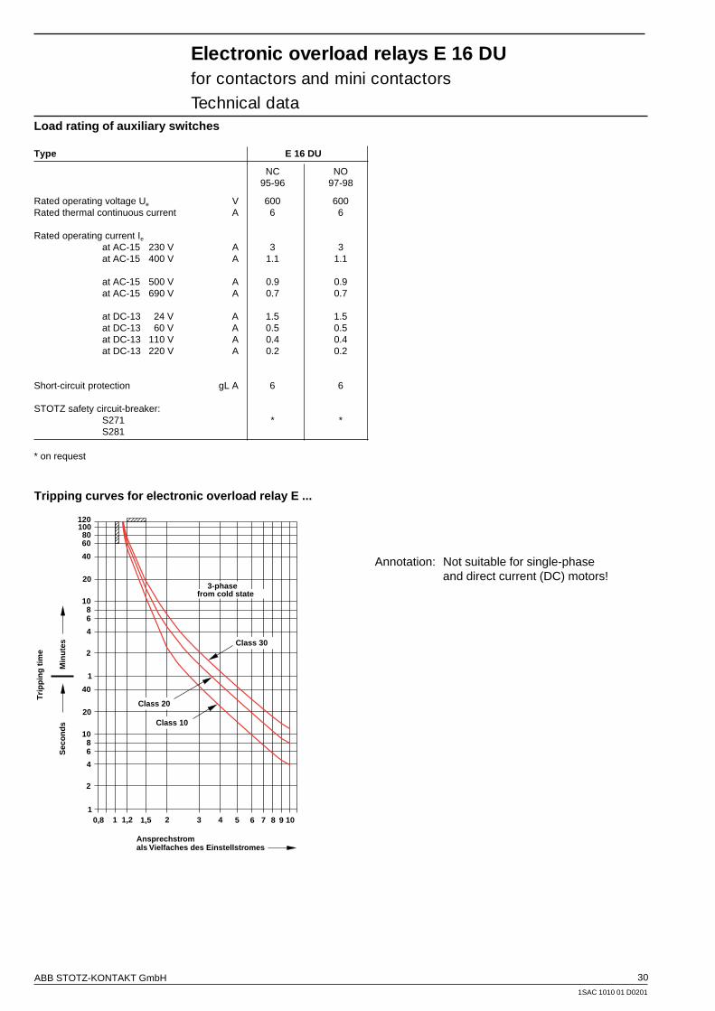
ABB STOTZ-KONTAKT GmbH 30
1SAC 1010 01 D0201
Load rating of auxiliary switches
Type E 16 DU
NC NO95-96 97-98
Rated operating voltage Ue V 600 600Rated thermal continuous current A 6 6
Rated operating current Ie
at AC-15 230 V A 3 3at AC-15 400 V A 1.1 1.1
at AC-15 500 V A 0.9 0.9at AC-15 690 V A 0.7 0.7
at DC-13 24 V A 1.5 1.5at DC-13 60 V A 0.5 0.5at DC-13 110 V A 0.4 0.4at DC-13 220 V A 0.2 0.2
Short-circuit protection gL A 6 6
STOTZ safety circuit-breaker:S271 * *S281
* on request
Electronic overload relays E 16 DUfor contactors and mini contactorsTechnical data
Ansprechstromals Vielfaches des Einstellstromes
0,8 1 1,2 1,5 2 3 4 5 6 7 8 9 101
2
4
68
10
20
40
Class 30
1201008060
Sec
on
ds
Min
ute
s
Tri
pp
ing
tim
e 2
4
68
10
20
40
1
Class 20
Class 10
3-phasefrom cold state
Tripping curves for electronic overload relay E ...
Annotation: Not suitable for single-phaseand direct current (DC) motors!

ABB STOTZ-KONTAKT GmbH 31
1SAC 1010 01 D0201
Approvals Ships' classification societies
GermanNational
StandardsLaboratory
PTBUL CSA Ex ,,e“ * GL LRS BV DNV
USA Canada Germany Germany Great Britain France Norway
L L l L L L L
L L l L L L L
L L l L L L L
L L l L L L L
L L l L L L L
L Normal version approved;rating plates bear the test mark if mandatory
l Submitted for approval
* Protection of intrinsically safe motors (EN 50019) class Ex "e" to DIN VDE 0165/02.91(= Protection of intrinsically safe motors (EN 50019) of enclosure increased safety "e" in accordancewith the provisions for "Installation of electrical systems in explosion-hazard areas" to DIN VDE 0165/02.91.)
Electronic overload relays E 16 DUfor contactors and mini contactorsTechnical data
Setting range Short-circuit protection (fuses, miniature circuit-breakers) Resistance Power lossper phase per phaseat upper
gL/gG setting currentA ... A A W W
Electronic overload relay E 16 DU
0.1 ... 0.32 1 0.97 0.10.3 ... 1.00 4 0.113 0.110.9 ... 2.70 10 0.014 0.12.0 ... 6.30 20 0.0024 0.15.7 ... 18.90 50 0.0008 0.29
Approvals and certificates
Resistances and power losses
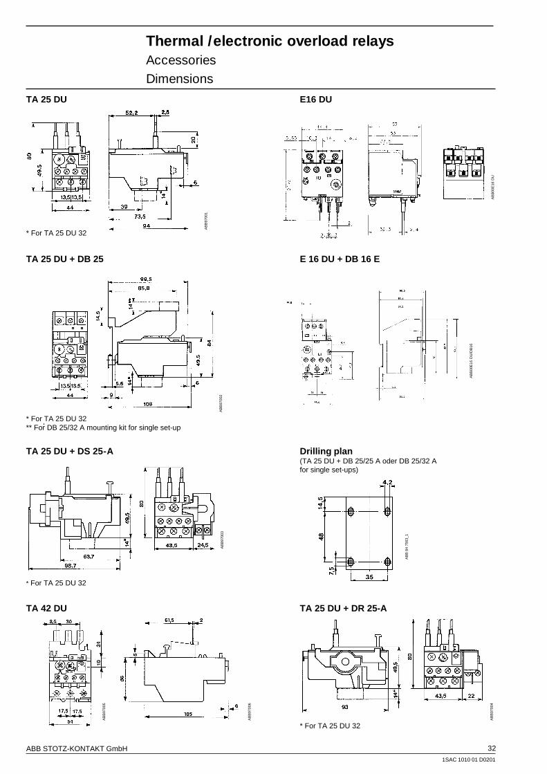
ABB STOTZ-KONTAKT GmbH 32
1SAC 1010 01 D0201
Thermal /electronic overload relaysAccessoriesDimensions
TA 25 DU E16 DU
* For TA 25 DU 32
TA 25 DU + DB 25 E 16 DU + DB 16 E
* For TA 25 DU 32** For DB 25/32 A mounting kit for single set-up
TA 25 DU + DS 25-A Drilling plan(TA 25 DU + DB 25/25 A oder DB 25/32 Afor single set-ups)
* For TA 25 DU 32
TA 42 DU TA 25 DU + DR 25-A
* For TA 25 DU 32
AB
B 8
4 75
63_1
AB
B97
004
AB
B97
005
AB
B97
006
AB
B97
001
AB
B97
002
AB
B97
003
AB
B00
E16
DU
/DB
16
AB
B00
E16
DU

ABB STOTZ-KONTAKT GmbH 33
1SAC 1010 01 D0201
Thermal overload relaysAccessoriesDimensions
TA 75 DU TA 80 DU
* For TA 75 DU 80
TA 42 DU, TA 75 DU, TA 80 DU + DB 80 Drilling plan(TA 42 DU, TA 75 DU und TA 80 DU + DB 80for single set-up)
TA 110 DU
AB
B97
007
AB
B97
008
AB
B97
009
SS
T 0
79 9
1 M
/1
SS
T 0
80 9
1 M
SS
T 0
79 9
1 M
/2
AB
B97
010
SS
T T
A11
0DU
E02
15D
9
126
136
78
ø 6.2
E02
15D
9
(M6)

ABB STOTZ-KONTAKT GmbH 34
1SAC 1010 01 D0201
T / TA 450 DU/SU T 900 DU/SU
SS
T 0
37 9
0 M
Thermal overload relaysAccessoriesDimensions
T / TA 200 DU
(dimensions in mm)
(M6)
120
140
E02
23D
5
AB
B T
A20
0DU
E02
33D
5
SS
T 0
36 9
0 M

ABB STOTZ-KONTAKT GmbH 35
1SAC 1010 01 D0201
Electronic overload relaysAccessoriesDimensions
E 200 DU
E 320 DU
E 500 DU E 800 DU
(dimensions in mm)
AB
B E
200D
U
AB
B E
320D
U
AB
B E
500D
U
AB
B E
800D
U

ABB STOTZ-KONTAKT GmbHP.O.BOX 101680D-69006 HeidelbergTelephone ++49 62 21 / 7 01-00Telefax ++49 62 21 / 7 01-1115
Internet http://www.abb.de/sst
Pub
licat
ion
no: 1
SA
C 1
010
01 D
0201
Prin
ted
in G
erm
any
(02/
01)


