Technical Note00840-0100-3045, Rev BASeptember 2015
Material Selection and Compatibility Considerations for Rosemount® Pressure Transmitters
FOR MORE INFORMATION ON ROSEMOUNT PRESSURE TRANSMITTERS:
Contact an Emerson™ representative:
1-800-999-9307Visit Rosemount.com
Technical Note00840-0100-3045, Rev BA
Rosemount Pressure TransmittersSeptember 2015
1.1 Introduction
The potential for damage due to corrosion is an important concern in the design of instrumenta-tion for most process control systems. Rosemount pressure transmitters are available with several choices of materials of construction that can be expected to perform well in a wide range of applications. This technical data sheet briefly discusses some of the reasons why incompati-bilities occur and the problems that can result. References are given to assist the user in making the appropriate material choices for an application.
The information presented here is intended only as a guide to the selection of material options. Any material will behave differently under the influence of such variables as temperature, pressure, flow rate, abrasives, and contaminants. All of the components of a process fluid should be considered when selecting materials. Fluids of a homogeneous chemical composition may react differently with a material than fluids of a heterogeneous composition. Additionally, even the presence of trace amounts of a chemical will impact material selection. It is the user's responsibility to make a careful analysis of all process parameters when specifying materials. Emerson Process Management cannot guarantee that a material is suited to a particular application under all possible process conditions.
If materials other than the standard materials discussed here are needed, contact your local Emerson sales office for assistance.
1.2 Corrosion basics
Corrosion is the gradual destruction of a metal by chemical or electrochemical means. The most generic form of corrosion is galvanic corrosion. A combination of a cathode, an anode, and an electrolyte must be present for this type of corrosion to occur. This combination of cathode, anode, and electrolyte is called a galvanic cell. Simply stated, a galvanic cell consists of two electrically connected, dissimilar metals and a medium, usually an aqueous solution, by which electron transfer can take place.
To fully understand the corrosion process, these terms must be better defined.
Anode — The electrode at which chemical oxidation occurs (or + current leaves the electrode and enters the electrolyte).
Cathode — The electrode at which chemical reduction occurs (or + current enters the electrode from the electrolyte).
A potential difference results when the electrically connected anode and cathode are separated by a physical distance in a conductive media. This potential difference causes the positively charged cations to flow from the anode to the cathode through the conductive medium. To complete the circuit, the negatively charged electrons flow from the anode to the cathode through the electrical connection. The resulting corrosion takes place at the anode. The cathode may also corrode, but not to the same extent.
The loss of electrons by the anode is called oxidation, and it causes the metal surface to become positively charged. These positively charged metal ions on the surface, called cations, attract the negative ions (anions) found in the electrolyte to form a new compound. This new compound no longer has its former metal characteristics, but rather it takes a new form such as rust or iron oxide.
2 Pressure
Technical Note00840-0100-3045, Rev BA
Rosemount Pressure TransmittersSeptember 2015
The gain of electrons at the cathode is referred to as reduction. Reduction allows the metal at the cathode area to retain its metallic characteristics (see Figure 1-1 on page 3).
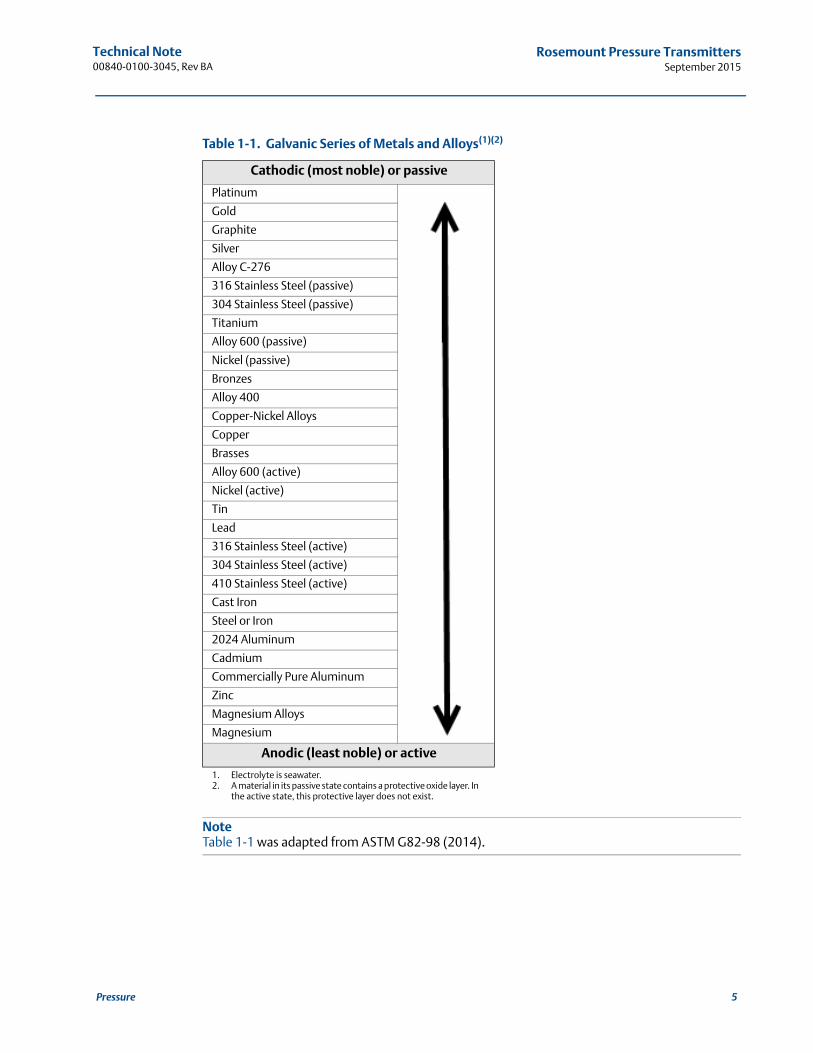
The tendency for corrosion to occur is governed by the magnitude of potential difference developed between the anode and the cathode. Generally, those metals with the highest potentials are at the anodic end of the galvanic series (see Table 1-1).
Metals with the lowest potentials are at the cathodic end of the series. However, the level of potential can vary with different conditions and with different environments. In general, the farther apart the metals are positioned on the galvanic chart, the more likely they are to corrode when placed together in a solution.
1.3 Types of corrosion
Generally, all corrosion is interrelated; however, it can take many forms. Corrosion can be uniform or localized. It may also combine with other forms of attack to produce even more undesirable effects. In the following discussion, some of the most common forms of corrosion are presented, including a separate section on sulfide stress cracking.
1.3.1 Uniform corrosion
This is characterized by an even distribution of corrosion that leaves the surface clean or coated with corrosion products. This even distribution is due to the movement of the anodic and cathodic sites on the metal's surface. With uniform attack, fouling of the metal is usually a bigger problem than failure.
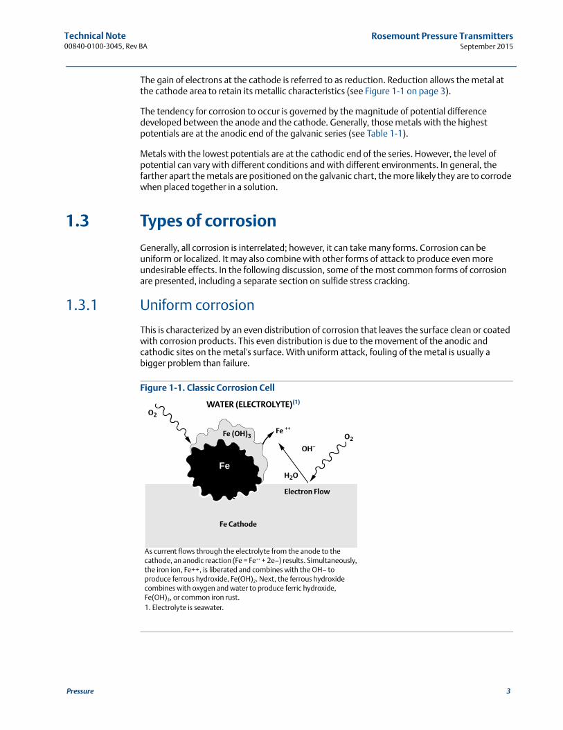
Figure 1-1. Classic Corrosion Cell
As current flows through the electrolyte from the anode to the cathode, an anodic reaction (Fe = Fe++ + 2e–) results. Simultaneously, the iron ion, Fe++, is liberated and combines with the OH– to produce ferrous hydroxide, Fe(OH)2. Next, the ferrous hydroxide combines with oxygen and water to produce ferric hydroxide, Fe(OH)3, or common iron rust. 1. Electrolyte is seawater.
Fe (OH)3Fe ++
OH–
H2O
Electron Flow
Fe Cathode
WATER (ELECTROLYTE)(1)
O2
O2
Fe
3Pressure
Technical Note00840-0100-3045, Rev BA
Rosemount Pressure TransmittersSeptember 2015
4 Pressure
1.3.2 Pitting
One of the most destructive forms of corrosion is pitting. It is a form of localized attack that causes small holes to form in the metal. It is promoted by low-velocity, stagnant-type conditions where concentrated “bubbles” of corrosives could form. Pitting is often difficult to detect because the pits may be covered by corrosion by-products. Pitting may take months to years before its effects are visible.
However, once started, a pit penetrates the metal at an ever increasing rate. Pitting also has a tendency to undercut the surface. This makes detection even more difficult and subsurface damage more severe than the surface condition appears.
1.3.3 Galvanic corrosion
When two dissimilar metals come into contact and are immersed in a conductive medium, an electric potential develops. The corrosion rate of the more active (anodic) metal increases whiles the corrosion rate of the more noble (cathodic) metal decreases. The resulting corrosion can be uniformly distributed or localized.
1.3.4 Erosion-corrosion
Erosion-corrosion is the increase in rate of attack on a metal from abrasive effects. It can be characterized by grooves, holes, and waves, but usually exhibits a directional pattern. This form of corrosion is more common in the softer metals, and usually occurs after the protective film on the surface of the metal has been stripped away.
Technical Note00840-0100-3045, Rev BA
Rosemount Pressure TransmittersSeptember 2015
NoteTable 1-1 was adapted from ASTM G82-98 (2014).
Table 1-1. Galvanic Series of Metals and Alloys(1)(2)
1. Electrolyte is seawater.2. A material in its passive state contains a protective oxide layer. In
the active state, this protective layer does not exist.
Cathodic (most noble) or passive
Platinum
Gold
Graphite
Silver
Alloy C-276
316 Stainless Steel (passive)
304 Stainless Steel (passive)
Titanium
Alloy 600 (passive)
Nickel (passive)
Bronzes
Alloy 400
Copper-Nickel Alloys
Copper
Brasses
Alloy 600 (active)
Nickel (active)
Tin
Lead
316 Stainless Steel (active)
304 Stainless Steel (active)
410 Stainless Steel (active)
Cast Iron
Steel or Iron
2024 Aluminum
Cadmium
Commercially Pure Aluminum
Zinc
Magnesium Alloys
Magnesium
Anodic (least noble) or active
5Pressure
Technical Note00840-0100-3045, Rev BA
Rosemount Pressure TransmittersSeptember 2015
6 Pressure
1.3.5 Stress corrosion
By definition, Stress Corrosion Cracking (SCC) is a phenomenon that, by virtue of the simultaneous application of a tensile stress and corrosive environment, promotes a brittle-type failure at stress levels well below the yield strength of the metal. The higher the tensional stress, the shorter the time to failure. Although time to cracking at low stress levels may be long, there is no practical minimum stress below which the possibility of cracking is eliminated, given sufficient time in a critical environment.
For austenitic steels, such as type 316 stainless, the two major damaging ions are hydroxide and chloride (OH- and Cl-).
1.3.6 Crevice corrosion
This localized corrosion occurs within crevices and other shielded areas on the metal surface. The solution within the crevice becomes highly concentrated and acidic. Crevice corrosion might occur inside holes, at metal-to-metal surfaces, and on sealing surfaces.
1.3.7 Intergranular corrosion
This form of corrosion is a selective attack on the grain boundaries (the surface of crystal mismatch between adjacent grains) of a metal without appreciable attack on the grains (individual crystal of a microstructure) themselves. The attack mechanism results from a difference in potential between the grain boundaries and the grain. Because welding often causes segregation of impurities at grain boundaries, or precipitation of intermetallics, welded areas are a common source of intergranular corrosion. The attack causes a loss of strength and ductility much greater than the loss due to the amount of metal destroyed.
1.3.8 Hydrogen embrittlement
Almost all metals lose ductility when they absorb hydrogen. This is especially noticeable at temperatures below 100 °C. The exact mechanism involved is still undetermined; however, the leading theories suggest that hydrogen causes a highly localized alteration of the metallic bonds at a flaw or crack tip under stress. This may either decrease the cohesive strength of the bonds or lower the shear stress required for slip. In either case, the metal fractures in a brittle manner at loads well below the macroscopic yield strength of the structure.
Hydrogen embrittlement is a common problem when tantalum is placed in hydrogen service.
1.3.9 Hydrogen permeation
Hydrogen permeation is the process where hydrogen atoms diffuse through the metal isolating diaphragm into the sensor module fill fluid by either an interstitial mechanism or a vacancy mechanism. Although the mechanism is much more involved, for the sake of simplicity, this definition will be sufficient.
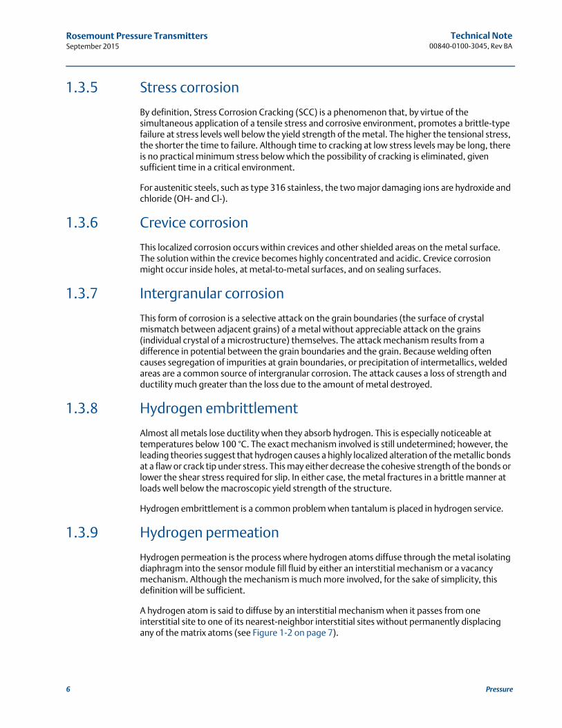
A hydrogen atom is said to diffuse by an interstitial mechanism when it passes from one interstitial site to one of its nearest-neighbor interstitial sites without permanently displacing any of the matrix atoms (see Figure 1-2 on page 7).
Technical Note00840-0100-3045, Rev BA
Rosemount Pressure TransmittersSeptember 2015
7Pressure
Figure 1-2. Path of Atom Diffusion by Interstitial Mechanism
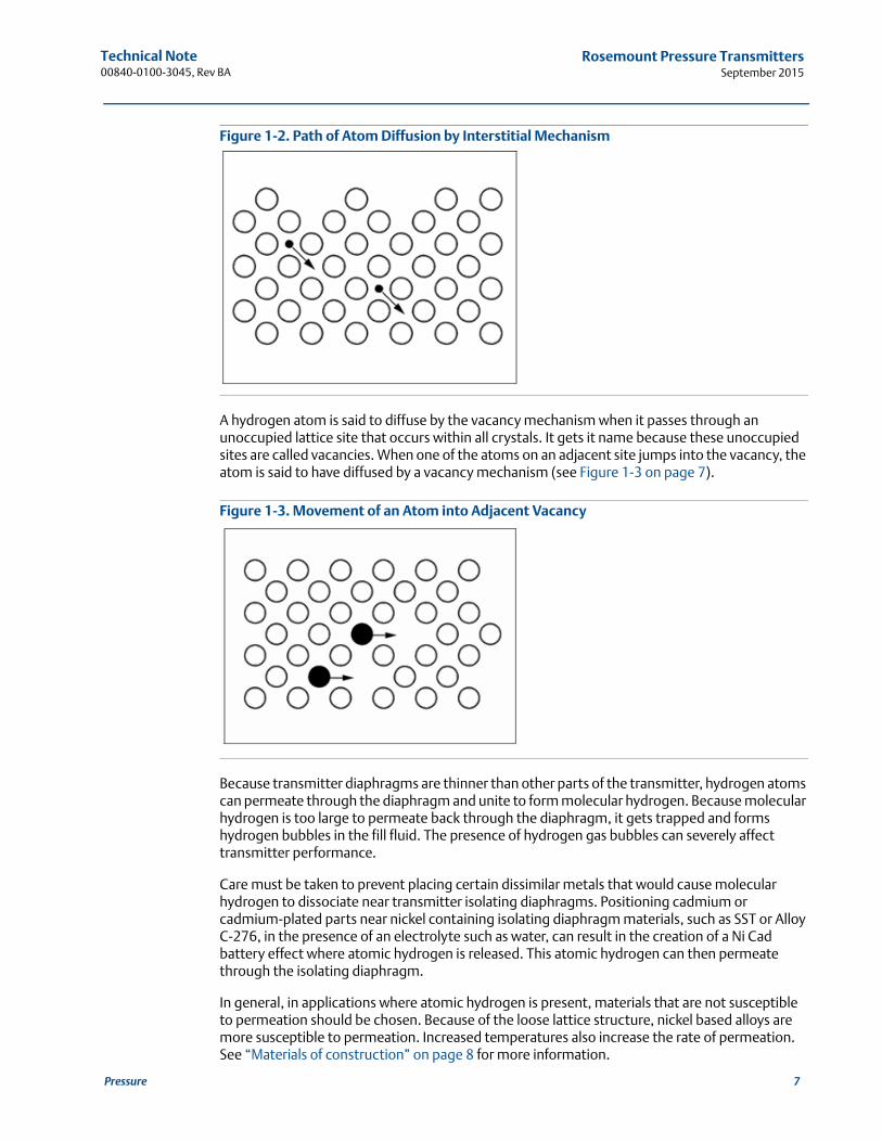
A hydrogen atom is said to diffuse by the vacancy mechanism when it passes through an unoccupied lattice site that occurs within all crystals. It gets it name because these unoccupied sites are called vacancies. When one of the atoms on an adjacent site jumps into the vacancy, the atom is said to have diffused by a vacancy mechanism (see Figure 1-3 on page 7).
Figure 1-3. Movement of an Atom into Adjacent Vacancy
Because transmitter diaphragms are thinner than other parts of the transmitter, hydrogen atoms can permeate through the diaphragm and unite to form molecular hydrogen. Because molecular hydrogen is too large to permeate back through the diaphragm, it gets trapped and forms hydrogen bubbles in the fill fluid. The presence of hydrogen gas bubbles can severely affect transmitter performance.
Care must be taken to prevent placing certain dissimilar metals that would cause molecular hydrogen to dissociate near transmitter isolating diaphragms. Positioning cadmium or cadmium-plated parts near nickel containing isolating diaphragm materials, such as SST or Alloy C-276, in the presence of an electrolyte such as water, can result in the creation of a Ni Cad battery effect where atomic hydrogen is released. This atomic hydrogen can then permeate through the isolating diaphragm.
In general, in applications where atomic hydrogen is present, materials that are not susceptible to permeation should be chosen. Because of the loose lattice structure, nickel based alloys are more susceptible to permeation. Increased temperatures also increase the rate of permeation. See “Materials of construction” on page 8 for more information.
Technical Note00840-0100-3045, Rev BA
Rosemount Pressure TransmittersSeptember 2015
8 Pressure
1.3.10 Sulfide stress cracking
Sulfide stress cracking is a common form of corrosion in oil field environments. When exposed to “sour” environments, sulfide stress cracking may occur in susceptible materials. Sour environments can be defined as a fluid containing liquid water and hydrogen sulfide such as sour gas and sour crude.
The rapidity with which hydrogen atoms absorbed on a metal surface combine to form molecular H2 is affected by the catalytic properties of the electrode surface. If a catalyst poison like hydrogen sulfide is present, the rate of formation of molecular H2 is decreased, while the accumulation of absorbed hydrogen on the electrode surface is increased. The increased concentration of surface hydrogen favors entrance of hydrogen atoms into the metal lattice, causing hydrogen embrittlement. In some stressed, high-strength ferrous alloys it may also induce spontaneous hydrogen cracking.
1.4 Materials of construction
Rosemount pressure transmitters include a wide variety of materials of construction to cover almost any application. The following discussion will aid in the understanding of various materials offered. It should be noted that for special applications, other materials of construction not listed in this paper may be offered. Only the most widely used materials are presented.
1.4.1 Type 316 stainless steel
Alloys with a chromium content over 11 percent and an iron content well over 50 percent are known as stainless steels. The designation “stainless steels” can be attributed to their ability to withstand most corrosives under many conditions.
Type 316 stainless steel (16-18Cr and 10-14Ni) belongs to the group of austenitic stainless steels. This group is essentially nonmagnetic and cannot be hardened by heat treatment. The nickel content contributes to the improved corrosion resistance, and it is also responsible for the retention of the austenitic structure.
Type 316 SST has a high resistance to corrosion. It is rust resistant in the atmosphere and is resistant to most concentrations of nitric acid. However, it is attacked by nonoxidizing acids such as sulfuric and hydrochloric acid in most concentrations.
Most salt solutions have little effect on type 316 SST, although the halide salts (fluorine, chlorine, bromine, iodine) can cause severe pitting and possibly stress-corrosion cracking.
Type 316 SST performs very well against hydrogen diffusion and is a good choice as a diaphragm material when the process is hydrogen gas.
Type 316 SST has good resistance to alkaline solutions, organic acids, and other organic compounds.
1.4.2 Nickel-based alloys
Nickel is the basis of an important group of materials used for corrosive applications. High-nickel alloys provide good resistance to a wide variety of corrosives. The nickel content helps provide good resistance as well as good physical and mechanical properties.
Technical Note00840-0100-3045, Rev BA
Rosemount Pressure TransmittersSeptember 2015
9Pressure
In general, nickel alloys have the basic corrosion resistance of nickel combined with the added resistance associated with the alloyed metal. This combination makes the alloy as good as, or even better than, nickel against corrosion.
Alloy-400
Alloy-400 (67Ni-33Cu) has good resistance at ambient temperatures to most of the nonoxidizing acids, such as hydrofluoric, sulfuric, and phosphoric acids. It also resists nonoxidizing salts. The nickel in the alloy improves its resistance toward alkalies.
One challenge with Alloy-400 material is that it is more susceptible to hydrogen permeation. Therefore, Alloy-400 should not be used as a diaphragm material when the process is hydrogen gas or when hydrogen atoms are present unless other protection mechanisms, such as gold plating, are used (see “Gold-plated materials” on page 10). Gold-plated Alloy-400 may be a good choice for Hydrofluoric Acid service.
Alloy C-276
In Alloy C-276 (54Ni-16Mo-16Cr), chromium and molybdenum are added to nickel to improve the alloy's resistance to oxidizing conditions. This alloy also retains a considerable degree of resistance to nonoxidizing conditions. For example, Alloy C-276 withstands oxidizing acids and also the acid salts such as ferric and cupric chlorides. Hydrochloric and sulfuric acids in most concentrations do not affect Alloy C-276 at moderate temperatures. Alloy C-276 is well suited to provide protection against alkalies, organic acids, and other organic compounds.
C-276 can be susceptible to hydrogen permeation and is thus not the best fit for hydrogen rich applications. If hydrogen permeation is a risk, gold-plated 316 SST or gold-plated Alloy-400 should be considered (see “Gold-plated materials” on page 10).
Both Alloy-400 and Alloy C-276 have excellent corrosion resistance against atmospheric conditions and fresh water. In addition, Alloy C-276 is resistant to stagnant seawater.
1.4.3 Tantalum
Tantalum has proven to be a useful material in corrosive applications involving hydrochloric acid and acidic ferric chloride solutions. This accounts for the wide acceptance of tantalum in the chemical industry. Tantalum has a high melting point and good strength even at elevated temperatures. Its high strength allows thin sections to be used. This is important because tantalum is very expensive.
Tantalum has superior corrosive resistance to most acids, chemical solutions, and organic compounds. In general, tantalum has good resistance to hydroiodic, hydrobromic, boiling hydrochloric, nitric, phosphoric, and sulfuric acids. Liquid metals generally do not affect tantalum. In addition, it has good resistance to most other acids. However, tantalum can be attacked severely by hydrofluoric acid, fluosilicic acid, hot fuming sulfuric acid, and fluorine. Also, it is attacked by strong alkaline solutions and by fused alkalies.
Tantalum can suffer severe embrittlement if in service with high-temperature oxygen or nitrogen, or with hydrogen at any temperature.
1.4.4 Nickel-plated carbon steel
Nickel plating is an effective means for giving metal surfaces a corrosion resistant coating. Nickel has good resistance against most of the common acids, except those of an oxidizing nature such as nitric acid. In general, neutral and alkaline solutions leave nickel relatively
Technical Note00840-0100-3045, Rev BA
Rosemount Pressure TransmittersSeptember 2015
unattacked. It has good resistance to the milder forms of atmospheric conditions, to oxidation, to higher temperatures, and to halogen gases.
Nickel-plated flanges and adapters can be used along with Alloy C-276 diaphragms. The large difference in potentials that is created between the use of cadmium-plated flanges and Alloy C-276 diaphragms is now eliminated.
1.4.5 Gold-plated materials
Adhering a thin layer of gold to a base metal will provide protection against hydrogen permeation. Gold plating is suggested in applications where atomic hydrogen is present. It is not necessary for all hydrogen service applications. The strength of the atomic bonding for hydrogen gas, for example, is strong enough that dissociation is unlikely. The base metal which gold plating is applied should be chosen to provide suitable corrosion resistance, unless there is some other contributing factor. Alloy-400 is typically used as a base metal in hydrofluoric (HF) acid applications where the weaker bond between hydrogen and fluoride may result in the presence of hydrogen atoms. In other applications, 316L SST base metal may provide sufficient corrosion resistance and lower the cost of the isolating diaphragm material.
1.5 Components of a transmitter
Components that make up a transmitter can be separated into two groups, wetted and non-wetted, depending on whether or not they come into direct contact with the process. When selecting materials for wetted and non-wetted components one should consider the exposure environment.
1.5.1 Wetted components
Wetted components are those that come into direct contact with the process, which include process isolating diaphragms, drain/vent valves, process flange, and O-rings. Selecting the correct materials for a wetted component requires detailed knowledge of the process, such as the operating pressures, temperatures, and the process fluid. This section outlines how to use this information to select the correct material for all the wetted components.
Process isolating diaphragms
The process isolating diaphragm separates the sensor fill fluid from the process it is measuring. It is important to select a material that is compatible to the process, otherwise the transmitter could experience failure. Rosemount pressure transmitters are available with process isolating diaphragms in the following materials, although not all materials are available with all transmitters.
316L SST (UNS S31603)
Alloy C-276 (UNS N10276)
Alloy 400 (UNS N04400)
Tantalum (UNS R05440)
Gold-Plated Alloy 400
Gold-Plated 316L SST
10 Pressure
Technical Note00840-0100-3045, Rev BA
Rosemount Pressure TransmittersSeptember 2015
Implications
There are several items to consider when selecting a material for the process isolating diaphragm.
The relative thickness of the process isolating diaphragm is considerably less than other wetted parts. It is critical to select a material that is compatible with the process.
Gold plating options are available to help prevent hydrogen permeation through the sensor modules isolating diaphragm and into the fill fluid.
Tantalum process isolating diaphragms are most commonly used in applications that are highly corrosive or acidic.
Drain/vent valves
Drain/vent valves are located on the flange or manifold attached to the transmitter and are used to drain or vent the process from the transmitter. Rosemount pressure transmitters are available with drain/vent valves in the following materials, although not all materials are available with all transmitters:
316L SST (UNS S31603)
Alloy C-276 (UNS N10276)
Alloy 400/K-500 (Drain vent seat: Alloy 400; Drain vent stem: Alloy K-500)
Implications
When selecting a drain/vent valve there are several implications to keep in mind.
316L SST drain/vent valves are not compliant with NACE MR0175/ISO 15156 and MR0103.
For NACE applications, 316 SST flanges with Alloy C-276 drain/vent valves are commonly used.
Alloy 400/K-500 drain/vent valves are not compliant with NACE MR0175/ISO 15156 and MR0103.
Alloy 400/K-500 drain/vent valves are only available with flange material Cast Alloy 400; they are not available with Level transmitter or direct-mount configurations.
Process flanges and flange adapters
The process flange or flange adapter is used to connect the transmitter to the process. Rosemount pressure transmitters are available with process flanges and flange adapters in the following materials, although not all materials are available with all transmitters:
Plated carbon steel
CF-8M (Cast 316 SST) (UNS J92900)
Cast C-276: CW-12MW-1 (UNS N10276)
Cast Alloy 400: M-30C (UNS N04400)
Implications
Cast Alloy 400 flanges are only available with drain/vent material Alloy 400/K-500.
11Pressure
Technical Note00840-0100-3045, Rev BA
Rosemount Pressure TransmittersSeptember 2015
12 Pressure
Wetted O-rings
The wetted O-rings are used to seal the sensing diaphragms to the flange or manifold, as well as sealing flange adapters to flanges. Rosemount pressure transmitters are available with wetted O-rings in the following materials:
Glass-filled PTFE
Graphite-filled PTFE
Graphite (available as a special option)
Implications
There are some things to consider when choosing a material for the wetted O-rings.
Glass-filled PTFE wetted O-rings adds wear resistance and offers good compression strength. They should not be used in applications containing Fluorine or Hydrofluoric Acid.
Graphite-filled PTFE wetted O-ring is supplied with gold-plated Alloy 400 isolating diaphragm.
Temperature limits are identical for graphite-filled and glass-filled PTFE.
Technical Note00840-0100-3045, Rev BA
Rosemount Pressure TransmittersSeptember 2015
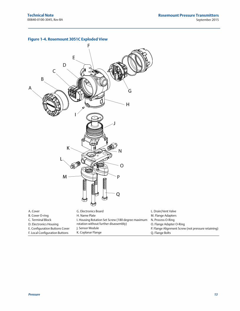
Figure 1-4. Rosemount 3051C Exploded View
A. CoverB. Cover O-ringC. Terminal BlockD. Electronics HousingE. Configuration Buttons CoverF. Local Configuration Buttons
G. Electronics BoardH. Name PlateI. Housing Rotation Set Screw (180 degree maximum rotation without further disassembly)J. Sensor ModuleK. Coplanar Flange
L. Drain/Vent ValveM. Flange AdaptersN. Process O-RingO. Flange Adapter O-RingP. Flange Alignment Screw (not pressure retaining)Q. Flange Bolts
A
B
E
H
K
L
I
M
J
N
O
P
Q
C
G
D
F
13Pressure
Technical Note00840-0100-3045, Rev BA
Rosemount Pressure TransmittersSeptember 2015
14 Pressure
1.5.2 Non-wetted components
Non-wetted components are those that don't come into direct contact with the process, including bolts, electronics housings, cover O-rings, and mounting brackets. Selecting the correct materials for a non-wetted component requires knowledge of the environment, such as ambient temperatures, humidity and corrosive conditions.
Bolts
Bolts are used to attach the transmitter to the flange or manifold. Although bolting is not process wetted, environmental conditions can impact material selection. Rosemount pressure transmitters are available with bolts in the following materials:
ASTM A449, Type 1 (zinc-cobalt plated carbon steel)–standard material
ASTM F593G, Condition CW1 (Austenitic 316 SST)
ASTM A453, Grade 660, Class D, SST
ASTM A193, Grade B7M alloy steel
ASTM A193, Grade B8M, Class 2, SST
Alloy K-500, ASTM F468
Implications
In applications requiring compliance with NACE MR0175/ISO 15156 and NACE MR0103, bolting must meet requirements if they are directly exposed to the H2S environment either directly or because of insulation. Bolting compliant with NACE MR0175/ISO 15156 and NACE MR0103 are listed below.
ASTM A453, Grade 660, Class D, SST
ASTM A193, Grade B7M alloy steel
Electronics housing
The electronics housing is the enclosure surrounding the electronics board and terminal block to ensure they are protected from the environment and can function reliably. Rosemount pressure transmitters are available with electronics housings in the following materials:
Low-copper aluminum alloy
CF-8M (Cast 316 SST)
Engineered Polymer
Implications
The standard painted aluminum housing is suitable for the majority of industrial environments. Stainless steel is typically used in marine environments.
The aluminum housing uses polyurethane paint.
Engineered Polymer is only available on wireless transmitters with internal antennas and has no conduit entries.
Technical Note00840-0100-3045, Rev BA
Rosemount Pressure TransmittersSeptember 2015
Sensor module fill fluid
Sensor module fill fluid is contained behind the process isolating diaphragms and transmits the source pressure from the process to the sensor. Rosemount pressure transmitters are available with sensor module fill fluids in the following materials:
Silicone
Coplanar configurations use Halocarbon for the inert fill fluid option.
In-Line configurations use Fluorinert™ FC-43 for the inert fill fluid option.
Implications
It is important to select a fill fluid that is compatible with the process fluid should the sensor module isolating diaphragm become damaged. If this occurs, fill fluid can contact the process.
Silicone fill fluid is standard. Inert fill fluids are typically used in applications where silicone fill fluid may be reactive with the process.
Inert fill fluid has reduced operating limits compared to silicone fill fluid. Inert fill fluids are not available with coplanar absolute pressure measurement types.
Inert fill fluids are not available with wireless transmitters.
1.6 Material related standards and certifications
When selecting the materials of construction for a pressure transmitter, compliance with certain standards is often a requirement. Emerson Process Management offers a wide range of material related standards and certifications, and understanding what each of them means can help identify those that are needed.
1.6.1 NACE MR0175/ISO 15156:2009 and NACE MR0103-2012
Sulfide stress cracking is a major concern in environments containing sour oil or gas. An environment is characterized as 'sour' by the presence of hydrogen sulfide (H2S), which is extremely corrosive and can exist as either a gas or a solution. Exposed components in sour environments that are not sufficiently resistant to hydrogen sulfide are likely to fail. Picking the right material is essential.
NACE MR0175/ISO 15156 (EN 2004), “Materials for Use in H2S-Containing Environments in Oil and Gas Production”, is a material standard for petroleum production, drilling, gathering and flow line equipment, and field processing facilities. NACE MR0175/ISO 15156 provides material requirements and application limits defined by environmental composition and pH, temperature range, and H2S partial pressure in which these materials can be used.
NACE MR0103 is specifically for sour refinery process environments and was developed because refineries are outside the scope of NACE MR0175/ISO 15156. The NACE MR0103 standard establishes material requirements for resistance to sulfide stress cracking. Requirements are also established for metal fabrication such as weldments.
15Pressure
Technical Note00840-0100-3045, Rev BA
Rosemount Pressure TransmittersSeptember 2015
16 Pressure
Implications
When choosing the materials for each of the transmitter components with NACE MR0175/ISO 15156 or NACE MR0103 in mind, there are several things to consider.
The standards only apply to the process wetted materials. NACE MR0175/ISO 15156 does not apply when the hydrogen sulfide content is less than 15 mol% and the partial pressure is less than 10psia (0.07MPa abs). Thus, components such as the transmitter housing do not need to comply.
The standards only ensure an appropriate resistance to sulfide stress corrosion, not total immunity.
NACE MR0175/ISO 15156 does not apply specifically to low-pressure environments. Refer to the standard for details.
Certification - Q15, Q25
Rosemount transmitters are available with certification of compliance for both NACE MR0175/ISO 15156 and NACE MR0103 with product shipments at request.
ISO 15156/NACE MR0175 is available by selecting option code Q15.
NACE MR0103 is available by selecting option code Q25.
1.6.2 Material traceability
No manufacturing process is perfectly repeatable. Variations in chemical proportions, environmental conditions and manufacturing procedures cause small differences in a material's properties. To show that each material is within the specified tolerances, manufacturers test samples from each material batch. Associating the test results with each material in a final product is referred to as material traceability.
Implications
Regardless of which materials are selected, material traceability offers several benefits when ordering a transmitter.
It provides proof that each component is constructed from the specified materials.
It ensures the materials provided meet the specifications set for that material.
Certification - Q8
Rosemount pressure transmitters are available with a Material Inspection Certificate, compliant with ISO 10474 3.1B/EN 10204 3.1, to document the material traceability. The included documentation is unique to each unit, and contains the follow items:
Customer Information
Manufacturer Information
Rosemount Model Number
Referenced Component and Corresponding Heat Number
Certificate Issue Date
Material Test Reports
Material Compliance Statement
Technical Note00840-0100-3045, Rev BA
Rosemount Pressure TransmittersSeptember 2015
17Pressure
The Material Inspection Certificate is provided with the product shipment for all models containing the option code Q8. Documentation provided is retained for five years and can be re-created upon request.
1.6.3 Positive material identification
Positive Material Identification (PMI) uses a x-ray fluorescence spectrometer to identify the material composition by percentage of its base elements. This provides a non-destructive verification of the material and confirms the composition on the Q8 certification (see “Certification - Q8” on page 16).
Implications
PMI has several implications for the selection of component materials.
PMI confirms that the chemical composition of the material meets the applicable specifications.
PMI only confirms chemical composition, it does not measure physical performance properties, such as hardness or strength.
Emerson Process Management provides PMI on process wetted, pressure containing components upon request.
Material Traceability Certification (Q8) must be ordered as an option if PMI testing is required.
Certification - Q76
Rosemount transmitters are available with a PMI Certificate, compliant with ISO 10474 3.1B/EN 10204 3.1, to document the PMI testing that has been performed. This document can be ordered as a separate line on an order applicable to the entire order.
1.6.4 Special service cleaning
In specialty gas services, such as those containing oxygen, contamination can be a serious concern. Insufficient cleanliness of a component in contact with the process can result in combustion, or affect product purity. Special service cleaning ensures that the surfaces of all wetted components are cleaned using methods defined by ASTM G93, “Standard Practice for Cleaning Methods and Cleanliness Levels for Material and Equipment Used in Oxygen-Enriched Environments” so the process is not affected.
Implications
When ordering special service cleaning there are several items to consider.
After cleaning, components are visually inspected to look for moisture, debris, or organic materials.
Once special service cleaning has been performed, all cleaned parts are sealed in a plastic bag and should remain sealed until installation.
It is common practice to use inert sensor module fill fluids in applications requiring special service cleaning.
When a transmitter and manifold assembly receives special service cleaning, both items must be purchased with this option. Graphite-packed manifolds are not available with special service cleaning.
Technical Note00840-0100-3045, Rev BA
Rosemount Pressure TransmittersSeptember 2015
18 Pressure
Certification - Q6
Rosemount pressure transmitters are available with a Certificate of Special Service Cleaning that states the compliance with ISO 10474 3.1B/EN 10204 3.1, and that the cleaning has been performed. The documentation is unique to each order and contains the following items:
Customer Information
Manufacturer Information
Rosemount Model Number
Issue Date
Compliance Statement
Special service cleaning can be ordered using option codes P2, P3, or PA in the product model code. Documentation provided is retained for five years and can be re-created upon request.
1.6.5 ISO 9001:2008
To ensure maximum product quality and repeatability, Emerson Process Management has a robust quality management system for Rosemount pressure transmitters that complies with all the requirements of ISO 9001:2008. This system is firmly established, implemented, maintained and continually improved to meet the vary needs of Emerson Process Management’s customers and all applicable regulations. The full details of this quality management system are available in the Rosemount Quality Manual.
Implications
Emerson Process Management’s commitment to quality has several implications to consider when ordering the materials for a pressure transmitter.
The quality management system applies to the entire organization, so all products and services offered by Emerson Process Management meet the high quality standards.
ISO 9001 requires frequent audits by an independent organization, which ensures continuous compliance with all stated quality systems.
Certification - Q1, Q2
Rosemount transmitters are available with a certification that confirms the products shipped meet all applicable standards and contracts, in accordance with ISO 9001:2008. This certification is available with option code Q1. It is also available notarized with option code Q2.
The full Rosemount Quality Manual (document number 00809-0100-1742) is also available for ordering.
Technical Note00840-0100-3045, Rev BA
Rosemount Pressure TransmittersSeptember 2015
1.7 Material selection references
Schweitzer, Philip A., P.E. Corrosion Resistance Tables: Metals, Nonmetals, Coatings, Mortars, Plastics, Elastomers and Linings, and Fabrics. Third Edition, Marcel Dekker, Inc., 1991.
National Association of Corrosion Engineers. Corrosion Data Survey, Metals Section, 6th Edition, 1985.
ASM Metals Handbooks, Volume 13 (Corrosion), 9th Edition, American Society of Metals, Sept. 1987.
Cor-sur and Cor-sur2, personal computer software versions of Corrosion Data Survey for Metals and Non-metals, National Association of Corrosion Engineers and National Bureau of Standards. PO Box 218340, Houston, TX 77218.
Corrosion Data Survey for Metals and Non-metals, National Association of Corrosion Engineers and National Bureau of Standards. PO Box 218340, Houston, TX 77218.
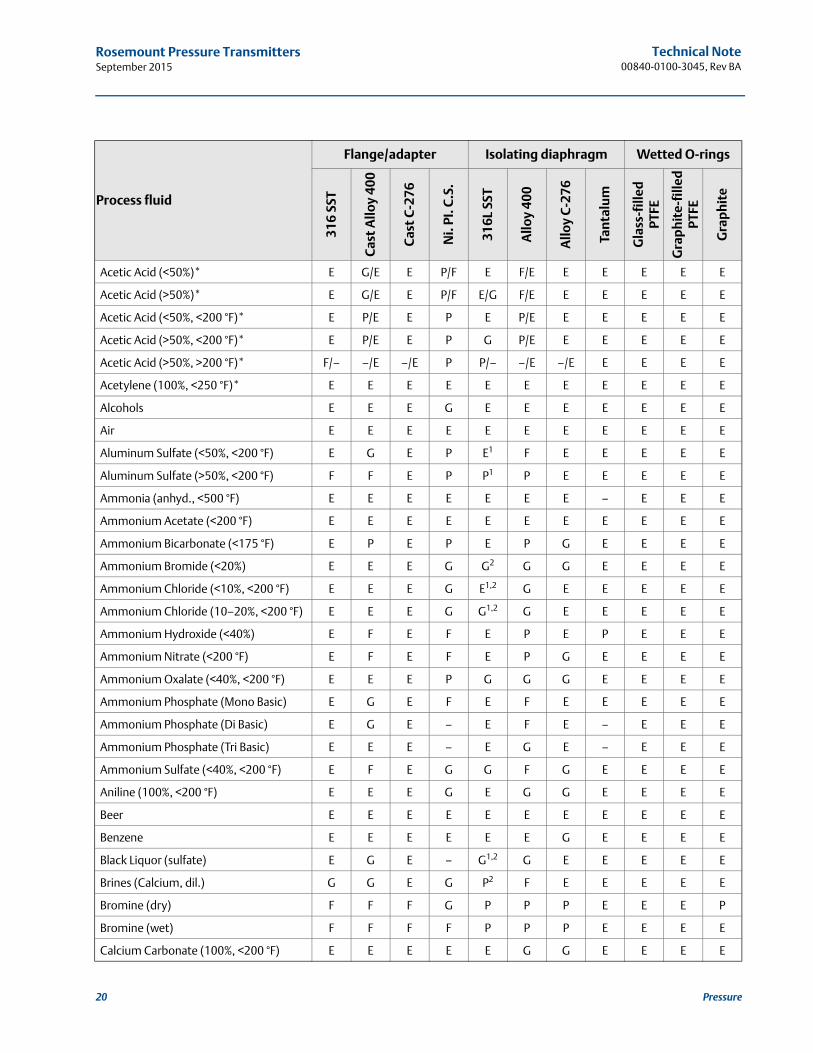
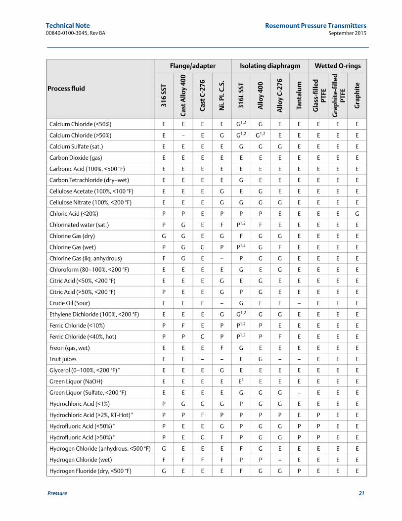
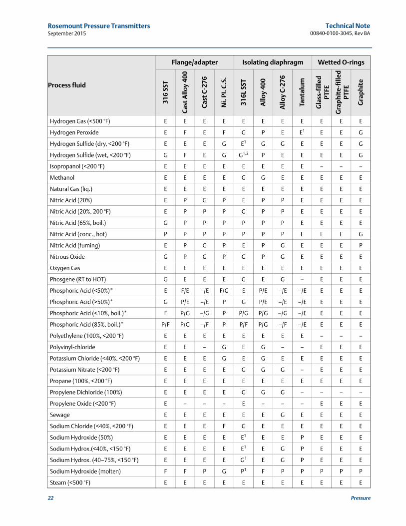
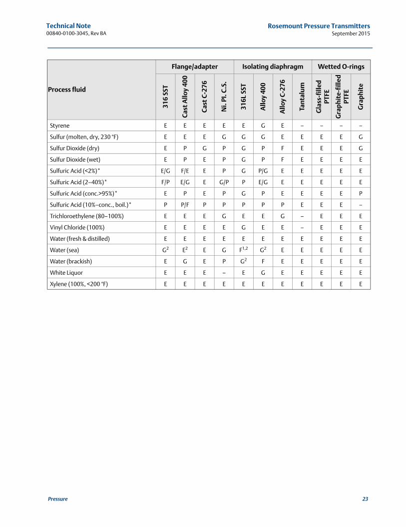
1.8 Materials selection guide(1)
E = Excellent resistance. Corrosion rate <0.002 in. (0.05 mm) per year. Best choice for diaphragm material.
G = Good resistance. Corrosion rate <0.020 in. (0.50 mm) per year.
F = Fair resistance. Corrosion rate 0.020–0.050 in. (0.50–1.27 mm) per year.
P = Poor resistance. Corrosion rate >0.050 in. (1.27 mm) per year.
– = Data not available.
(The numeric values for corrosion rate hold true only for selecting the isolating diaphragm, not for selecting the flange and adapter materials. When selecting the flange/adapter and O-ring materials, the “E, G, F, and P” ratings describe the performance of that material as excellent, good, fair, and poor.)
1 = May cause stress corrosion cracking
2 = May cause pitting, especially for low velocity or stagnant fluid conditions
* = Process fluid can be either aerated or non-aerated. If there is a significant difference in performance of the material, two letters may be separated by a slash (aerated/non-aer-ated data).
NoteAll data is based on a temperature of 70 °F (20 °C) unless noted otherwise.Since a material’s resistance to corrosion can vary greatly due to many factors such as impurities, temperature, pressure, velocity, etc., this chart should be used only as a general guide.Emerson Process Management makes no guarantee for the suitability of any transmitter material. The responsibility for material selection rests with the user.
1. Data for material selection guide compiled from NACE publication Corrosion Data Survey, metals section, sixth edition.
19Pressure
Technical Note00840-0100-3045, Rev BA
Rosemount Pressure TransmittersSeptember 2015
Process fluid
Flange/adapter Isolating diaphragm Wetted O-rings
316
SST
Cas
t A
lloy
400
Cas
t C
-276
Ni.
PI. C
.S.
316L
SST
Allo
y 40
0
Allo
y C
-276
Tan
talu
m
Gla
ss-f
illed
PT
FE
Gra
ph
ite-
fille
dPT
FE
Gra
ph
ite
Acetic Acid (<50%)* E G/E E P/F E F/E E E E E E
Acetic Acid (>50%)* E G/E E P/F E/G F/E E E E E E
Acetic Acid (<50%, <200 °F)* E P/E E P E P/E E E E E E
Acetic Acid (>50%, <200 °F)* E P/E E P G P/E E E E E E
Acetic Acid (>50%, >200 °F)* F/– –/E –/E P P/– –/E –/E E E E E
Acetylene (100%, <250 °F)* E E E E E E E E E E E
Alcohols E E E G E E E E E E E
Air E E E E E E E E E E E
Aluminum Sulfate (<50%, <200 °F) E G E P E1 F E E E E E
Aluminum Sulfate (>50%, <200 °F) F F E P P1 P E E E E E
Ammonia (anhyd., <500 °F) E E E E E E E – E E E
Ammonium Acetate (<200 °F) E E E E E E E E E E E
Ammonium Bicarbonate (<175 °F) E P E P E P G E E E E
Ammonium Bromide (<20%) E E E G G2 G G E E E E
Ammonium Chloride (<10%, <200 °F) E E E G E1,2 G E E E E E
Ammonium Chloride (10–20%, <200 °F) E E E G G1,2 G E E E E E
Ammonium Hydroxide (<40%) E F E F E P E P E E E
Ammonium Nitrate (<200 °F) E F E F E P G E E E E
Ammonium Oxalate (<40%, <200 °F) E E E P G G G E E E E
Ammonium Phosphate (Mono Basic) E G E F E F E E E E E
Ammonium Phosphate (Di Basic) E G E – E F E – E E E
Ammonium Phosphate (Tri Basic) E E E – E G E – E E E
Ammonium Sulfate (<40%, <200 °F) E F E G G F G E E E E
Aniline (100%, <200 °F) E E E G E G G E E E E
Beer E E E E E E E E E E E
Benzene E E E E E E G E E E E
Black Liquor (sulfate) E G E – G1,2 G E E E E E
Brines (Calcium, dil.) G G E G P2 F E E E E E
Bromine (dry) F F F G P P P E E E P
Bromine (wet) F F F F P P P E E E E
Calcium Carbonate (100%, <200 °F) E E E E E G G E E E E
20 Pressure
Technical Note00840-0100-3045, Rev BA
Rosemount Pressure TransmittersSeptember 2015
Calcium Chloride (<50%) E E E E G1,2 G E E E E E
Calcium Chloride (>50%) E – E G G1,2 G1,2 E E E E E
Calcium Sulfate (sat.) E E E E G G G E E E E
Carbon Dioxide (gas) E E E E E E E E E E E
Carbonic Acid (100%, <500 °F) E E E E E E E E E E E
Carbon Tetrachloride (dry–wet) E E E E G E E E E E E
Cellulose Acetate (100%, <100 °F) E E E G E G E E E E E
Cellulose Nitrate (100%, <200 °F) E E E G G G G E E E E
Chloric Acid (<20%) P P E P P P E E E E G
Chlorinated water (sat.) P G E F P1,2 F E E E E E
Chlorine Gas (dry) G G E G F G G E E E E
Chlorine Gas (wet) P G G P P1,2 G F E E E E
Chlorine Gas (liq. anhydrous) F G E – P G G E E E E
Chloroform (80–100%, <200 °F) E E E E G E G E E E E
Citric Acid (<50%, <200 °F) E E E G E G E E E E E
Citric Acid (>50%, <200 °F) P E E G P G E E E E E
Crude Oil (Sour) E E E – G E E – E E E
Ethylene Dichloride (100%, <200 °F) E E E G G1,2 G G E E E E
Ferric Chloride (<10%) P F E P P1,2 P E E E E E
Ferric Chloride (<40%, hot) P P G P P1,2 P F E E E E
Freon (gas, wet) E E E F G E E E E E E
Fruit Juices E E – – E G – – E E E
Glycerol (0–100%, <200 °F)* E E E G E E E E E E E
Green Liquor (NaOH) E E E E E1 E E E E E E
Green Liquor (Sulfate, <200 °F) E E E E G G G – E E E
Hydrochloric Acid (<1%) P G G G P G G E E E E
Hydrochloric Acid (>2%, RT-Hot)* P P F P P P P E P E E
Hydrofluoric Acid (<50%)* P E E G P G G P P E E
Hydrofluoric Acid (>50%)* P E G F P G G P P E E
Hydrogen Chloride (anhydrous, <500 °F) G E E E F G E E E E E
Hydrogen Chloride (wet) F F F F P P – E E E E
Hydrogen Fluoride (dry, <500 °F) G E E E F G G P E E E
Process fluid
Flange/adapter Isolating diaphragm Wetted O-rings
316
SST
Cas
t A
lloy
400
Cas
t C
-276
Ni.
PI. C
.S.
316L
SST
Allo
y 40
0
Allo
y C
-276
Tan
talu
m
Gla
ss-f
illed
PT
FE
Gra
ph
ite-
fille
dPT
FE
Gra
ph
ite
21Pressure
Technical Note00840-0100-3045, Rev BA
Rosemount Pressure TransmittersSeptember 2015
22 Pressure
Hydrogen Gas (<500 °F) E E E E E E E E E E E
Hydrogen Peroxide E F E F G P E E1 E E G
Hydrogen Sulfide (dry, <200 °F) E E E G E1 G G E E E G
Hydrogen Sulfide (wet, <200 °F) G F E G G1,2 P E E E E G
Isopropanol (<200 °F) E E E E E E E E – – –
Methanol E E E E G G E E E E E
Natural Gas (liq.) E E E E E E E E E E E
Nitric Acid (20%) E P G P E P P E E E E
Nitric Acid (20%, 200 °F) E P P P G P P E E E E
Nitric Acid (65%, boil.) G P P P P P P E E E E
Nitric Acid (conc., hot) P P P P P P P E E E G
Nitric Acid (fuming) E P G P E P G E E E P
Nitrous Oxide G P G P G P G E E E E
Oxygen Gas E E E E E E E E E E E
Phosgene (RT to HOT) G E E E G E G – E E E
Phosphoric Acid (<50%)* E F/E –/E F/G E P/E –/E –/E E E E
Phosphoric Acid (>50%)* G P/E –/E P G P/E –/E –/E E E E
Phosphoric Acid (<10%, boil.)* F P/G –/G P P/G P/G –/G –/E E E E
Phosphoric Acid (85%, boil.)* P/F P/G –/F P P/F P/G –/F –/E E E E
Polyethylene (100%, <200 °F) E E E E E E E E – – –
Polyvinyl-chloride E E – G E G – – E E E
Potassium Chloride (<40%, <200 °F) E E E G E G E E E E E
Potassium Nitrate (<200 °F) E E E E G G G – E E E
Propane (100%, <200 °F) E E E E E E E E E E E
Propylene Dichloride (100%) E E E E G G G – – – –
Propylene Oxide (<200 °F) E – – – E – – – E E E
Sewage E E E E E E G E E E E
Sodium Chloride (<40%, <200 °F) E E E F G E E E E E E
Sodium Hydroxide (50%) E E E E E1 E E P E E E
Sodium Hydrox.(<40%, <150 °F) E E E E E1 E G P E E E
Sodium Hydrox. (40–75%, <150 °F) E E E E G1 E G P E E E
Sodium Hydroxide (molten) F F P G P1 F P P P P P
Steam (<500 °F) E E E E E E E E E E E
Process fluid
Flange/adapter Isolating diaphragm Wetted O-rings
316
SST
Cas
t A
lloy
400
Cas
t C
-276
Ni.
PI. C
.S.
316L
SST
Allo
y 40
0
Allo
y C
-276
Tan
talu
m
Gla
ss-f
illed
PT
FE
Gra
ph
ite-
fille
dPT
FE
Gra
ph
ite
Technical Note00840-0100-3045, Rev BA
Rosemount Pressure TransmittersSeptember 2015
Styrene E E E E E G E – – – –
Sulfur (molten, dry, 230 °F) E E E G G G E E E E G
Sulfur Dioxide (dry) E P G P G P F E E E G
Sulfur Dioxide (wet) E P E P G P F E E E E
Sulfuric Acid (<2%)* E/G F/E E P G P/G E E E E E
Sulfuric Acid (2–40%)* F/P E/G E G/P P E/G E E E E E
Sulfuric Acid (conc.>95%)* E P E P G P E E E E P
Sulfuric Acid (10%–conc., boil.)* P P/F P P P P P E E E –
Trichloroethylene (80–100%) E E E G E E G – E E E
Vinyl Chloride (100%) E E E E G E E – E E E
Water (fresh & distilled) E E E E E E E E E E E
Water (sea) G2 E2 E G F1,2 G2 E E E E E
Water (brackish) E G E P G2 F E E E E E
White Liquor E E E – E G E E E E E
Xylene (100%, <200 °F) E E E E E E E E E E E
Process fluid
Flange/adapter Isolating diaphragm Wetted O-rings
316
SST
Cas
t A
lloy
400
Cas
t C
-276
Ni.
PI. C
.S.
316L
SST
Allo
y 40
0
Allo
y C
-276
Tan
talu
m
Gla
ss-f
illed
PT
FE
Gra
ph
ite-
fille
dPT
FE
Gra
ph
ite
23Pressure

Technical Note00840-0100-3045, Rev BA
September 2015
Global HeadquartersEmerson Process Management 6021 Innovation Blvd.Shakopee, MN 55379, USA
+1 800 999 9307 or +1 952 906 8888+1 952 949 7001 [email protected]
North America Regional OfficeEmerson Process Management 8200 Market Blvd.Chanhassen, MN 55317, USA
+1 800 999 9307 or +1 952 906 8888+1 952 949 7001 [email protected]
Latin America Regional OfficeEmerson Process Management 1300 Concord Terrace, Suite 400Sunrise, Florida, 33323, USA
+1 954 846 5030+1 954 846 [email protected]
Europe Regional OfficeEmerson Process Management Europe GmbHNeuhofstrasse 19a P.O. Box 1046CH 6340 BaarSwitzerland
+41 (0) 41 768 6111
+41 (0) 41 768 6300 [email protected]Asia Pacific Regional OfficeEmerson Process Management Asia Pacific Pte Ltd1 Pandan CrescentSingapore 128461
+65 6777 8211+65 6777 0947 [email protected]
Middle East and Africa Regional OfficeEmerson Process Management Emerson FZE P.O. Box 17033,Jebel Ali Free Zone - South 2Dubai, United Arab Emirates
+971 4 8118100+971 4 8865465 [email protected]
Standard Terms and Conditions of Sale can be found at: www.rosemount.com\terms_of_sale.The Emerson logo is a trademark and service mark of Emerson Electric Co.Rosemount and Rosemount logotype are registered trademarks of Rosemount Inc.Fluorinert is a trademark of 3M.All other marks are the property of their respective owners.© 2015 Rosemount Inc. All rights reserved.


![Influence of ocean fronts on cetacean habitat selection ...cetus.ucsd.edu/Publications/Presentations/MAS... · CapstoneFinal_DCamacho [Compatibility Mode] Author: Greg Created Date:](https://cdn.vdocuments.net/doc/165x107/5f61ce1025554e090f0fee86/influence-of-ocean-fronts-on-cetacean-habitat-selection-cetusucsdedupublicationspresentationsmas.jpg)
