
Technical Specification VIBROCONTROL 6000 Compact monitor / 03.07 page 1
Technical Specification VIBRCONTROL 6000 Compact monitor
Applications • Continuous safety monitoring for machines of all types
• Continuous data acquisition of vibration data and other measurement variables
Measuring and monitoring absolute casing vibration Monitoring and assessment of machines according to DIN ISO 10816 Measuring and monitoring relative shaft vibration Monitoring and assessment of machines according to DIN ISO 7919 Measuring and monitoring rolling-element bearing condition Measuring and monitoring sm@rt value fault symptoms
Measuring and monitoring axial shaft position
Measuring and monitoring radial shaft position
Measuring and monitoring temperature and process values
Further applications are under preparation.

Technical Specification VIBROCONTROL 6000 Compact monitor / 03.07 page 2
Characteristics • An instrument configuration of the VIBROCONTROL 6000 Compact monitor may consist of 1 to 3 input
modules respective 1 to 6 channels for measuring and monitoring tasks
• Through flexible adaptation all the typical monitoring and machine protection requirements can be met
• sm@rt value monitoring using a measurement method specifically for individual fault symptoms of machines and machine components
• Digital signal processing (DSP) allows versatile and high processing speed together with high reliability, using fewer components
• Flexible monitoring function with wide-ranging performance; reaction time of only 5 ms is possible for special applications
• Potential-free outputs for alarming and signals to peripheral electronics; selectively relays can be controlled via voting logic
• Galvanically isolated measurement outputs as analogue current or voltage signals, updating of the output signal is extremely fast and is on the limits of technical possibility
• A high level of system dependability through complete self-monitoring with a central OK relay.
• Available with built-in power pack for AC or DC power.
• A connection is provided for an independent, redundant power supply.
• User terminal for local operation and display including English, German and French language support
• OPC interface for optional connection to a Windows PC (Process visualization, data export, data storage or plant-wide system integration).
• Protective housing for enclosing in an industrial environment can be supplied as an optional accessory

Technical Specification VIBROCONTROL 6000 Compact monitor / 03.07 page 3
Contents of this Technical Specification*
Machine monitoring with the VIBROCONTROL 6000 Compact monitor ................................................... 4 Monitoring tasks and measurement variables ........................................................................................ 5 Inputs for sensors and signals ................................................................................................................ 8 Sensor power and signal conditioning .................................................................................................... 8 Monitoring function.................................................................................................................................. 9 Analogue signal output ........................................................................................................................... 9 Digital Communication ............................................................................................................................ 9
The Basic configurations for the VIBROCONTROL 6000 Compact monitor............................................ 10
Overview ............................................................................................................................................... 10 The classic vibration monitor with vibration velocity sensor ................................................................. 11 Vibration measurement for output to peripheral control systems ......................................................... 12 The modern monitoring system with acceleration sensor .................................................................... 13 Monitoring of rolling-element bearing condition and casing vibration................................................... 15 The monitoring system for vibration, rolling-element bearing condition and process values ............... 17 The correct solution for monitoring relative shaft vibration ................................................................... 19 Monitoring of axial position ................................................................................................................... 20 Works default settings........................................................................................................................... 22 Parameters & setting ranges for measurements and monitoring ......................................................... 24
Hardware of the VIBROCONTROL 6000 Compact monitor..................................................................... 26
The Basic module ................................................................................................................................. 26 The connection modules....................................................................................................................... 27
Optional accessories................................................................................................................................. 34
VIBROCONTROL 6000 Compact monitor User terminal ..................................................................... 34 Protective housing for installing the VIBROCONTROL 6000 Compact monitor .................................. 35 in an industrial environment .................................................................................................................. 35 Installation accessoires......................................................................................................................... 36 Digital Communication .......................................................................................................................... 36 Sensors ................................................................................................................................................. 37
* The technical specification is not intended to replace the product handbook. All important information for commissioning, operation and the technical safety instructions should be taken from the product handbook and the individual instrument’s documentation. The instrument documentation is part of the standard delivery extent of a VIBROCONTROL 6000 compact monitor.

Technical Specification VIBROCONTROL 6000 Compact monitor / 03.07 page 4
Machine monitoring with the VIBROCONTROL 6000 compact monitor The VIBROCONTROL 6000 Compact monitor is designed mainly for continuous machine monitoring. It offers optimum and cost-effective monitoring to guarantee comprehensive machine protection with early fault detection. The installation of a VIBROCONTROL 6000 Compact monitor consists of sensors, with their installation accessories, (also intrinsically-safe if required) and one or more VIBROCONTROL 6000 Compact monitor with user-specific configuration. Why safety monitoring?
What is safety monitoring ? Safety monitoring provides immediate recognition of, and reaction to, changes in machine condition that may constitute a danger to personnel, machines and the environment. For safety monitoring, permanently-installed sensors, continuous measurement of vibration values and constant comparison of these values with predefined limit values are absolutely required. During daily operation the system provides warnings when vibration and other measurement variables deviate from their permissible levels. In a case where the measurements increase to critical levels, a shutdown of the machine can be initiated. To pass the measurements on to peripheral electronics galvanically isolated analogue outputs are available. The VIBROCONTROL 6000 Compact monitor meets all the essential requirements of API 670 – the definitive standard for safety monitoring of machines, used in particular in power stations and petrochemical plants.

Technical Specification VIBROCONTROL 6000 Compact monitor / 03.07 page 5
Monitoring tasks and measurement variables The VIBROCONTROL 6000 Compact monitor is suitable for a number of applications. The correct measurement process must always be effected to correspond to the monitoring task. Thus it is self-explanatory that various applications must be combined into one instrument, e.g. monitoring of vibration severity according to DIN ISO10816 and monitoring rolling-element bearing condition. Currently the following measurement and monitoring tasks can be carried out:
Monitoring task Measurement type
Absolute casing vibration according DIN ISO 10816
RMS value of vibration velocity
Application Vibration monitoring according to DIN ISO 10816 serves for general purpose monitoring of a machine, where the dynamic forces on the rotor (e.g. from unbalance and deflection) are assessed as important symptoms for possible faults. As a rule rolling-element bearing damage cannot be identified by this measurement.
Rolling-element bearing condition
Bearing condition unit
Application Monitoring of rolling-element bearing condition is a sensible supplement to monitoring according to DIN ISO 10816. The BCU measurement method is suitable for monitoring the condition of rolling-element bearings in standard and high-speed machines.
Rolling-element bearing condition
Bearing condition bandpass (RMS value of vibration acceleration)
Application Monitoring of vibration acceleration serves for general purpose monitoring of a machine, where broad-band, structure-excited forces (e.g. from impact or stochastic excitation) are assessed as important symptoms for possible faults. This measurement method is especially suitable for the detection of rolling-element bearing damage in machines of all types, i.e. slow-, high-speed and standard machines.
Relative shaft vibration according to DIN ISO 7919
smax (Maximum excursion of the kinetic orbit)
Application Monitoring of the relative shaft vibration according to DIN ISO 7919 serves for monitoring of journal-bearing machines, where the vibration of the shaft relative to the housing (e.g. from unbalance or deflection) is mainly assessed for symptoms of possible faults.

Technical Specification VIBROCONTROL 6000 Compact monitor / 03.07 page 6
Monitoring task Measurement type
Axial shaft position
Quasi-static displacement measurement relative to a reference point
Application This is the most important monitoring task in turbo-machines and machines with axial journal bearings. Faulty loading of the machine can lead to machine destruction in milliseconds due to overloading of the thrust bearing. Early identification of a limit violation that may indicate a worn or damaged thrust bearing can prevent contact between rotating and stationary parts and seizing of the rotor.
Process values and temperature
Quasi-static measurement types
Application Monitoring of motor/bearing temperature and other important process values often permits early identification of faults and disturbances in the machine. In general process values are also very helpful in the assessment of machine vibrations, which many times are based on high vibration values only with unfavourable machine operating conditions.
sm@rt value – Fault symptoms at machine components
Measurement types specific to fault symptoms
Application In general machine faults cannot be clearly identified using a standard monitoring procedure according to DIN ISO 10816 resp. DIN ISO 7919. High vibration values alone cannot be used to reach an adequate conclusion about the actual cause of the fault. Conversely each machine component exhibits specific fault symptoms that can be used for early fault identification. With sm@rt technology * a measurement method is used that specifically targets the individual fault symptoms of machines and machine components. This allows conspicuous machine components to be identified and the danger potential of the fault to be assessed already during operation. The necessary corrective action according to the fault and the potential danger can then be planned and executed at an early stage.
Application examples Rotor unbalance, misalignment, gear wear, cavitation, degree of blade soiling, etc. sm@rt = Symptom monitoring at real time
User-defined monitoring tasks
Dynamic measurement types with user-defined signal filtering and signal detection
On enquiry
Application For user-defined task formulation
Further monitoring tasks are under preparation.

Technical Specification VIBROCONTROL 6000 Compact monitor / 03.07 page 7
Monitoring task
Measurement type
Axial shaft position
Quasi-static displacement measurement relative to a reference point
Application This is the most important monitoring task in turbo-machines and machines with axial journal bearings. Faulty loading of the machine can lead to machine destruction is milliseconds due to overloading of the thrust bearing. Early identification of a limit violation that may indicate a worn or damaged thrust bearing can prevent contact between rotating and stationary parts and seizing of the rotor.
Process values and temperature
Quasi-static measurement types
Application Monitoring of motor / bearing temperature and other important process values often permits early identification of faults and disturbances in the machine. In general process values are also very helpful in the assessment of machine vibrations, which many times are based on high vibration values only with unfavourable machine operating conditions.
sm@rt value –Fault symptoms at machine components
Measurement types specific to fault symptoms
Application In general machine faults cannot be clearly identified using a standard monitoring procedure according to DIN ISO 10816 resp. DIN ISO 7919. High vibration values cannot be used to reach an adequate conclusion about the actual cause of the fault. Conversely each machine component exhibits specific damage symptoms that can be used for early fault identification. With sm@rt technology * a measurement method is used that specifically targets the individual fault symptoms of machines and machine components. This allows conspicuous machine components to be identified and the danger potential of the fault to be assessed already during operation. The necessary corrective action according to the fault and the potential danger can then be planned and executed at an early stage.
Application examples Rotor unbalance, misalignment, gear wear, cavitation, degree of blade soiling, etc. sm@rt = Symptom monitoring at real time
Further monitoring tasks are under preparation.

Technical Specification VIBROCONTROL 6000 Compact monitor / 03.07 page 8
Inputs for sensors and signals The VIBROCONTROL 6000 Compact monitor is prepared for specific sensors and input signals that correspond to the monitoring task. Thus various instrument configurations can be delivered to suit various monitoring tasks (see Basic configurations). An instrument configuration of the VIBROCONTROL 6000 Compact monitor may consist of 1 to 3 input modules respective 1 to 6 channels for measuring and monitoring tasks. According to the task formulation and instrument configuration the following sensors and input signals can be connected:
Sensor type Sensor types
Vibration acceleration sensors (accelerometers) Vibration velocity sensors Non-contacting displacement sensors User-defined quasi-static signals User-defined dynamic voltage signals Under preparation: Phase reference sensors Under preparation: Binary inputs for status signals
With 8 mA constant-current supply (CCS) or –24 VDC power Series VS-06X or VS-07X Series SD, IN oder DS DC current or DC voltage signals Impulse voltage signals, e.g. for speed measurement
Sensor power and signal conditioning Each sensor connected to the VIBROCONTROL 6000 Compact monitor is handled in the optimum manner, because
• The power supply for connected sensor is specific to the type of sensor, e.g. constant-current 8 mA (CCS) or voltage –24 VDC / 30 mA
• The signal conditioning is dependent upon the connected sensor and the required measurement type; e.g. signal integration (0x, 1x, 2x), signal filtering (low-pass, high-pass), frequency response linearization for VS sensors (8 Hz or 15 Hz)

Technical Specification VIBROCONTROL 6000 Compact monitor / 03.07 page 9
Monitoring function The VIBROCONTROL 6000 Compact monitor is conceived for machine monitoring. For this purpose a measurement type is monitored for limit violation and events that occur are signalled to peripheral equipment by relay outputs.
Monitoring with reference to absolute limit values typically 2 alarm limits (Alert & Danger alarm) for each measurement type, as per case further alarm limits Limit values can be set to over- or under-violation Limit values and time delays infinitely adjustable within range Trip-multiplier function
Monitoring logic option Selectively either AND, OR or “2-of-3” voting logic is possible
Relay output For alarming and signalling of events to peripheral equipment
Analogue signal output The VIBROCONTROL 6000 Compact monitor can output the continuously acquired measurement value as an analogue signal. The DC output signals can be executed through galvanically isolated outputs to peripheral equipment as current or voltage signals.
Analogue DC outputs e.g. with standard 4-20 mA or 0-10 V signals The output signal is individually adjustable (linear, non-linear or with individually zoomed regions).
Digital Communication The VIBROCONTROL 6000 Compact monitor can also export the continuously acquired measurement value as digital data. An OPC interface which can be optionally integrated in a TCP/IP Ethernet network is available. Thus the VIBROCONTROL 6000 Compact monitor is a data source which makes your measured data and status information available to a VIBROCONTROL 6000 Compact monitor OPC server.
Digital Communication using OPC (OPC = OLE for process control) The VIBROCONTROL 6000 Compact monitor can communicate with any arbitrary PC in which the SIMS OPC Server Software has already been installed and taken into operation. The SIMS OPC server itself is an open interface, making data available to further systems for storage or visualization (e.g. to xms software with process visualization).

Technical Specification VIBROCONTROL 6000 Compact monitor / 03.07 page 10
The Basic configurations for the VIBROCONTROL 6000 Compact monitor
Overview
Order code Monitoring task
No. of channels
Sensor type AC power DC power
Page
CV-101-1-AC CV-101-1-DC 11 AS-CCS
CV-111-1-AC CV-111-1-DC 12
AS-24V CV-112-1-AC CV-112-1-DC 13 1x vibration
VS-8HZ CV-114-1-AC CV-114-1-DC 10
AS-CCS CV-111-2-AC CV-111-2-DC 12
AS-24V CV-112-2-AC CV-112-2-DC 13
Casing vibration according to
DIN ISO 10816
2x vibration
VS-8HZ CV-114-2-AC CV-114-2-DC 10
AS-CCS BC-121-2-AC BC-121-2-DC 14 Bearing condition BCU and casing vibration
2x BCU and vibration AS-24V BC-122-2-AC BC-122-2-AC 14
AS-CCS BC-221-2-AC BC-221-2-DC 15 Bearing condition BC-BP and casing vibration
2x BC-BP and vibration AS-24V BC-222-2-AC BC-222-2-AC 15
Bearing condition BC-BP, casing vibration and
process value
2x BC-BP and vibration
plus
2x process
value
AS-CCS
und
4-20mA
BC-221-2 / UD-121-2-AC
BC-221-2 / UD-121-2-DC
16
Relative shaft vibration according to DIN ISO 7919
2x vibration DS RV-117-2-AC RV-117-2-DC 18
1x static movement
DS AP-117-1-AC AP-117-1-DC 19
Axial shaft position
3x static movement
DS AP-327-3-AC AP-327-3-DC 20

Technical Specification VIBROCONTROL 6000 Compact monitor / 03.07 page 11
The classic vibration monitor with vibration velocity sensor For general purpose monitoring of machines, monitoring the RMS value of vibration velocity has been proven. This value is best acquired using vibration velocity sensors for optimum reliability and safety against interference. Traditionally a monitoring function is performed with 2 limit values and corresponding potential-free relay signals. In the case of slow-running machines a built-in frequency linearization takes care of the necessary adaptation.
Monitoring task
1-channel vibration
2-channel vibration
Order code CV-114-1-AC CV-114-1-DC CV-114-2-AC CV-114-2-DC Power supply 90...264 VAC 18...75 VDC 90...264 VAC 18...75 VDC Inputs No. of vibration channels Sensor connections Sensor power Sensor OK monitoring
1 1x velocity sensor e.g. VS-068, VS-069* not required yes
2 2x velocity sensor e.g. VS-068, VS-069* not required yes
Absolute casing vibration Measurement type Signal filtering Analogue signal output Monitoring Signalling Relay control
each sensor: 1x RMS value of vibration velocity in [mm/s] 10 Hz – 1 kHz (2 Hz – 1 kHz) each sensor: 1x 4-20 mA or 0-20 mA or 2-10 V or 0-10 V each sensor: 1x Alert alarm and 1x Danger alarm each sensor: 1x Alert relay and 1x Danger relay strict channel independence
Standard delivery extent Other Available accessories Works default settings Customer-defined settings
VIBROCONTROL 6000 Compact monitor including all necessary connection modules and connector set AC-4500 but excluding accessories (User terminal, sensors, etc.) see page 33ff see page 22f on enquiry (à dedicated form sheet CV-114-1-X resp. CV-114-2-X)
* Connections for VS-077 / VS-079 on enquiry

Technical Specification VIBROCONTROL 6000 Compact monitor / 03.07 page 12
Vibration measurement for output to peripheral control systems Vibration measurement is still a measurement task for the specialist, and the signal preparation and measurement value processing require special care and some expense. Normally the standards-conforming, assessed vibration signals are made available through potential-free
analogue outputs for peripheral equipment.
Monitoring task
1-channel vibration
Order code CV-101-1-AC CV-101-1-DC Power supply 90...264 VAC 18...75 VDC
Inputs No. of vibration channels Sensor connections Sensor power Sensor OK monitoring Absolute casing vibration Measurement type Signal filtering Analogue signal output
1 1x accelerometer, e.g. AS-062, 8325 constant-current (CCS), 8 mA yes 1x RMS value of vibration velocity in [mm/s] 10 Hz – 1 kHz (2 Hz – 1 kHz) 1x 4-20 mA or 0-20 mA or 2-10 V or 0-10 V
Standard delivery extent Other Available accessories Works default settings Customer-defined settings
VIBROCONTROL 6000 Compact monitor including all necessary connection modules and connector set AC-4500 but excluding accessories (User terminal, sensors, etc.) see page 33ff see page 22f on enquiry (à dedicated form sheet CV-101-1-X)
* Connection of other sensors on enquiry

Technical Specification VIBROCONTROL 6000 Compact monitor / 03.07 page 13
The modern monitoring system with acceleration sensor Modern acceleration sensors may also be used for monitoring of machines according to standards. In this case the desired measurement type is assessed by suitable conditioning of the signal. Limit value monitoring and alarm relay signalling are carried out in the customary manner. Acceleration sensors with CCS or with –24V power requirements can be used.
For CCS sensors:
Monitoring task
1-channel vibration
2-channel vibration
Order code CV-111-1-AC CV-111-1-DC CV-111-2-AC CV-111-2-DC Power supply 90...264 VAC 18...75 VDC 90...264 VAC 18...75 VDC Inputs No. of vibration channels Sensor connections Sensor power Sensor OK monitoring
1 1x accelerometer, e.g. AS-062 constant-current (CCS), 8 mA yes
2 2x accelerometer, e.g. AS-062 constant-current (CCS), 8 mA yes
Absolute casing vibration Measurement type Signal filtering Analogue signal output Monitoring Signalling Relay control
each sensor: 1x RMS value of vibration velocity in [mm/s] 10 Hz – 1 kHz (2 Hz – 1 kHz) each sensor: 1x 4-20 mA or 0-20 mA or 2-10 V or 0-10 V each sensor: 1x Alert alarm and 1x Danger alarm each sensor: 1x Alert relay and 1x Danger relay strict channel independence
Standard delivery extent Other Available accessories Works default settings Customer-defined settings
VIBROCONTROL 6000 Compact monitor including all necessary connection modules and connector set AC-4500 but excluding accessories (User terminal, sensors, etc.) see page 33ff see page 22f on enquiry (à dedicated form sheet CV-111-1-X resp. CV-111-2-X)

Technical Specification VIBROCONTROL 6000 Compact monitor / 03.07 page 14
For acceleration sensors with –24 V power requirement:
Monitoring task
1-channel vibration
2-channel vibration
Order code CV-112-1-AC CV-112-1-DC CV-112-2-AC CV-112-2-DC Power supply 90...264 VAC 18...75 VDC 90...264 VAC 18...75 VDC Inputs No. of vibration channels Sensor connections Sensor power Sensor OK monitoring
1 1x accelerometer, e.g. AS-022 Voltage –24 VDC / max. 30 mA yes
2 2x accelerometer, e.g. AS-022 Voltage –24 VDC / max. 30 mA yes
Absolute casing vibration Measurement type Signal filtering Analogue signal output Monitoring Signalling Relay control
each sensor: 1x RMS value of vibration velocity in [mm/s] 10 Hz – 1 kHz (2 Hz – 1 kHz) each sensor: 1x 4-20 mA or 0-20 mA or 2-10 V or 0-10 V each sensor: 1x Alert alarm and 1x Danger alarm each sensor: 1x Alert relay and 1x Danger relay strict channel independence
Standard delivery extent Other Available accessories Works default settings Customer-defined settings
VIBROCONTROL 6000 Compact monitor including all necessary connection modules and connector set AC-4500 but excluding accessories (User terminal, sensors, etc.) see page 33ff see page 22f on enquiry (à dedicated form sheet CV-112-1-X resp. CV-112-2-X)

Technical Specification VIBROCONTROL 6000 Compact monitor / 03.07 page 15
Monitoring of rolling-element bearing condition and casing vibration Rolling-element bearings are widely varied machine components. Because the peculiarities of rolling-element bearing damage are detectable only by suitable signal processes, monitoring of a rolling-element bearing condition parameter is done simultaneously with monitoring according to DIN / ISO. Such a monitoring system can e.g. be laid out for two sensors attached to two rolling-element bearing housings. Acceleration sensors with either CCS power or –24 V power requirements can be used.
Rolling-element bearing condition with classic BCU-measurement:
Monitoring task
2-channel vibration and rolling-element bearing condition BCU
Order code BC-121-2-AC BC-121-2-DC BC-122-2-AC BC-122-2-DC Power supply 90...264 VAC 18...75 VDC 90...264 VAC 18...75 VDC Inputs No. of vibration channels Sensor connections Sensor power Sensor OK monitoring
2 2x accelerometer, e.g. AS-062 constant-current (CCS), 8 mA yes
2 2x accelerometer, e.g. AS-022 Voltage –24 VDC / max. 30 mA yes
Absolute casing vibration Measurement type Signal filtering Analogue signal output Monitoring Signalling Relay control Bearing condition Measurement type Analogue signal output Monitoring Signalling Relay control
each sensor: 1x RMS value of vibration velocity in [mm/s] 10 Hz – 1 kHz (2 Hz – 1 kHz) each sensor: 1x 4-20 mA or 0-20 mA or 2-10 V or 0-10 V each sensor: 1x Alert alarm and 1x Danger alarm for both sensors: 1x Alert relay and 1x Danger relay OR linking both sensors for alert and danger separately each channel: 1x BCU (Bearcon condition unit) none each channel: 1x Alert alarm and 1x Danger alarm for both channels: 1x Alert relay and 1x Danger relay OR linking both sensors for alert and danger separately
Standard delivery extent Other Available accessories Works default settings Customer-defined settings
VIBROCONTROL 6000 Compact monitor including all necessary connection modules and connector set AC-4500 but excluding accessories (User terminal, sensors, etc.) see page 33ff see page 22f on enquiry (à dedicated form sheet BC-121-2-X resp. BC-122-2-X)

Technical Specification VIBROCONTROL 6000 Compact monitor / 03.07 page 16
Rolling-element bearing condition by monitoring vibration acceleration:
Monitoring task
2-channel vibration and rolling-element bearing condition BC-BP
(Bearing Condition Bandpass)
Order code BC-221-2-AC BC-221-2-DC BC-222-2-AC BC-222-2-DC Power supply 90...264 VAC 18...75 VDC 90...264 VAC 18...75 VDC Inputs No. of vibration channels Sensor connections Sensor power Sensor OK monitoring
2 2x accelerometer, e.g. AS-062 constant-current (CCS), 8 mA yes
2 2x accelerometer, e.g. AS-022 Voltage –24 VDC / max. 30 mA yes
Absolute casing vibration Measurement type Signal filtering Analogue signal output Monitoring Signalling Relay control Bearing condition Measurement type Signal filtering Analogue signal output Monitoring Signalling Relay control
each sensor: 1x RMS value of vibration velocity in [mm/s] 10 Hz – 1 kHz (2 Hz – 1 kHz) each sensor: 1x 4-20 mA or 0-20 mA or 2-10 V or 0-10 V each sensor: 1x Alert alarm and 1x Danger alarm for both sensors: 1x Alert relay and 1x Danger relay OR linking both sensors for alert and danger separately each sensor: 1x RMS value of vibration acceleration in [g] 1 kHz – 10 kHz none each sensor: 1x Alert alarm and 1x Danger alarm for both sensors: 1x Alert relay and 1x Danger relay OR linking both sensors for alert and danger separately
Standard delivery extent Other Available accessories Works default settings Customer-defined settings
VIBROCONTROL 6000 Compact monitor including all necessary connection modules and connector set AC-4500 but excluding accessories (User terminal, sensors, etc.) see page 33ff see page 22f on enquiry (à dedicated form sheet BC-221-2-X resp. BC-222-2-X)

Technical Specification VIBROCONTROL 6000 Compact monitor / 03.07 page 17
The monitoring system for vibration, rolling-element bearing condition and process values Many machines need the process values and temperatures (motor windings and bearings) to be taken into consideration and to be monitored as a supplementary measure to the monitoring of vibration and rolling-element bearing condition.

Technical Specification VIBROCONTROL 6000 Compact monitor / 03.07 page 18
Monitoring task
2-channel vibration and rolling-element bearing condition BC-BP
(Bearing Condition Bandpass) and
2-channels for process values 0/4-20mA
Order code BC-221-2 / UD-121-2-AC BC-221-2 / UD-121-2-DC Power supply 90...264 VAC 18...75 VDC
Inputs No. of vibration channels (AC channels) No. of process values (DC channels) Sensor connections Sensor power Sensor OK monitoring Absolute casing vibration Measurement type Signal filtering Analogue signal output Monitoring Signalling Relay control Bearing condition Measurement type Signal filtering Analogue signal output Monitoring Signalling Relay control Process values Measurement type Analogue signal output Monitoring Signalling Relay control
2 2 2x accelerometer, e.g. AS-062 2x process value inputs 4…20mA / 0...20mA each vibration channel: constant-current (CCS), 8mA yes each AC channel: 1x RMS value of vibration velocity in [mm/s] 10 Hz – 1 kHz (2 Hz – 1 kHz) each AC channel: 1x 4-20 mA or 0-20 mA or 2-10 V or 0-10 V each AC channel: 1x Alert alarm and 1x Danger alarm for both AC channels: 1x Alert relay and 1x Danger relay OR linking of both AC channels for alert and danger separately each AC channel: 1x RMS value of vibration acceleration in [g] 1 kHz – 10 kHz none each AC channel: 1x Alert alarm and 1x Danger alarm for both AC channels: 1x Alert relay and 1x Danger relay OR linking of both AC channels for alert and danger separately 2x Process values in unit dimension [eu] none each DC channel: 1x Alert alarm and 1x Danger alarm for both DC channels: 1x Alert alarm relay and 1x Danger alarm relay OR linking of both DC channels for alert and danger separately
Standard delivery extent Other Available accessories Works default settings Customer-defined settings
VIBROCONTROL 6000 Compact monitor including all necessary connection modules and connector set AC-4500 but excluding accessories (User terminal, sensors, etc.) see page 33ff see page 22f on enquiry (à dedicated form sheet BC-221-2 / UD-121-2-X)

Technical Specification VIBROCONTROL 6000 Compact monitor / 03.07 page 19
The correct solution for monitoring relative shaft vibration At journal-bearing machines it is preferable that the relative shaft vibration be monitored. The necessary sensor arrangement consists of two eddy-current displacement sensors (X/Y) at each measurement point,
mounted at 90° to one another. The measured signal from both sensors is monitored and assessed according to DIN ISO 7919.
Monitoring task
2-channel relative shaft vibration for one X/Y-bearing plane
Order code RV-117-2-AC RV-117-2-DC Power supply 90...264 VAC 18...75 VDC
Inputs No. of vibration channels Sensor connections Sensor power Sensor OK monitoring Relative shaft vibration Measurement type Signal filtering Analogue signal output Monitoring Signalling
2 2x displacement sensors, e.g. SD-052 with OD-052 each sensor: -24 VDC / max. 30 mA yes
1x smax in [µm] 10 Hz – 1 kHz (2 Hz – 1 kHz) 1x 4-20 mA or 0-20 mA or 2-10 V or 0-10 V 1x Alert alarm and 1x Danger alarm 1x Alert relay and 1x Danger relay
Standard delivery extent Other Available accessories Works default settings Customer-defined settings
VIBROCONTROL 6000 Compact monitor including all necessary connection modules and connector set AC-4500 but excluding accessories (User terminal, sensors, etc.) see page 33ff see page 22f on enquiry (à dedicated form sheet RV-117-2-X)

Technical Specification VIBROCONTROL 6000 Compact monitor / 03.07 page 20
Monitoring of axial position Machines with journal bearings for the rotor can be totally destroyed in seconds when rotating parts of the rotor come into contact with stationary parts. This ever-present danger can be eliminated only when the axial position of the rotor relative to the stator is continuously and reliably monitored.
Monitoring task
1-channel axial position
Order code AP-117-1-AC AP-117-1-DC Power supply 90...264 VAC 18...75 VDC
Inputs No. of DC channels Sensor connections Sensor power Sensor OK monitoring Axiale position Measurement type Analogue signal output Monitoring Signalling Relay control
1 1x displacement sensor, e.g. SD-052 with OD-052 each sensor: -24 VDC / max. 30 mA yes
1x DC (axial position) in [µm] 1x 4-20 mA or 0-20 mA or 2-10 V or 0-10 V
Alert high, Alert low, Danger high and Danger low 1x Alert relay and 1x Danger relay OR linking of the high and low limits for Alert and Danger separately
Standard delivery extent Other Available accessories Works default settings Customer-defined settings
VIBROCONTROL 6000 Compact monitor including all necessary connection modules and connector set AC-4500 but excluding accessories (User terminal, sensors, etc.) see page 33ff see page 22f on enquiry (à dedicated form sheet AP-117-1-X)

Technical Specification VIBROCONTROL 6000 Compact monitor / 03.07 page 21
Monitoring task
3-channel axial position with “2-of-3” voting logic
Order code AP-327-3-AC AP-327-3-DC Power supply 90...264 VAC 18...75 VDC
Inputs No. of DC channels Sensor connections Sensor power Sensor OK monitoring Axial position Measurement type Analogue signal output Monitoring Signalling Relay control
3 3x displacement sensor, e.g. SD-052 with OD-052 each sensor: -24 VDC / max. 30 mA yes
each channel: 1x DC (axial position) in [µm] each channel: 1x 4-20 mA or 0-20 mA or 2-10 V or 0-10 V each channel: Alert high, Alert low, Danger high and Danger low 1x Alert relay and 1x Danger relay “2-of-3” linking of all channels for Alert and Danger separately including OR linking of high and low limits
Standard delivery extent Other Available accessories Works default settings Customer-defined settings
VIBROCONTROL 6000 Compact monitor including all necessary connection modules and connector set AC-4500 but excluding accessories (User terminal, sensors, etc.) see page 33ff see page 22f on enquiry (à dedicated form sheet AP-327-3-X)

Technical Specification VIBROCONTROL 6000 Compact monitor / 03.07 page 22
Works default settings
Absolute casing vibration according to DIN ISO 10816 Input sensitivity For accelerometers 100 mV/g
For velocity sensors (e.g. VS-068/VS-069) 100 mV/mm/s
Measurement value RMS value of vibration velocity in the frequency range from 10Hz and 1 kHz
Measurement range 0...20 mm/s rms with crest factor 5 ( = 0...100 mm/s input range peak)
Averaging time 800 ms
DC output
4...20mA corresponds to 0...20 mm/s RMS
Monitoring
Alert alarm: limit value 7.1 mm/s; time delay 1 s Danger alarm: limit value 11 mm/s; time delay 1 s
Relay output
Alert relay: normally de-energized, non-latching Danger relay: normally de-energized, non-latching
Rolling-element bearing condition BCU Input sensitivity For accelerometers 100 mV/g
Measurement value BCU
Measurement range 0...100 BCU
Averaging time 1 s
Monitoring
Alert alarm: limit value 1 BCU; time delay 1 s Danger alarm: limit value 2 BCU; time delay 1 s
Relay output
Alert relay: normally de-energized, non-latching Danger relay: normally de-energized, non-latching
Rolling-element bearing condition BC-BP (bearing condition bandpass) Input sensitivity For accelerometers 100 mV/g
Measurement value RMS value of acceleration in the frequency range from 10Hz and 1 kHz
Measurement range 0...16 g RMS with crest factor 5 ( = 0...80 g peak value)
Averaging time 800 ms
Monitoring
Alert alarm: limit value 1 g; time delay 1 s Danger alarm: limit value 4 g; time delay 1 s
Relay output
Alert relay: normally de-energized, non-latching Danger relay: normally de-energized, non-latching

Technical Specification VIBROCONTROL 6000 Compact monitor / 03.07 page 23
Relative shaft vibration according to DIN ISO 7919, smax Input sensitivity For displacement sensors 8 mV/µm Measurement value smax in the frequency range from 10 Hz to 1 kHz
Measurement range 0...250 µm Peak detector rise time 3 ms, decay time 300 ms
DC output
4...20mA corresponds to 0... 250 µm
Monitoring
Alert alarm: limit value 50 µm; time delay 1 s
Danger alarm: limit value 70 µm; time delay 1 s
Relay output
Alert relay: normally de-energized, non-latching Danger relay: normally de-energized, non-latching
Axial shaft position Input sensitivity For displacement sensors 8 mV/µm Measurement value static movement (DC value) of axial shaft positition
Measurement range -1...+1 mm
Averaging time 1 s
DC output
4...20mA corresponds to –1...+1 mm
Monitoring
Alert alarm: limit value +/- 0,5 mm; time delay 1 s Danger alarm: limit value +/- 0,8 mm; time delay 1 s
Relay output
Alert relay: normally de-energized, non-latching Danger relay: normally de-energized, non-latching
Process value Input sensitivity 4...20 mA corresponds to 0...150 eu
Measurement value Quasi-static process value (DC value)
Measurement range 0...150 eu
Averaging time 1 s
Monitoring
Alert alarm: limit value 100 eu ; time delay 1 s Danger alarm: limit value 120 eu ; time delay 1 s
Relay output
Alert relay: normally-energized, non-latching Danger relay: normally de-energized, non-latching

Technical Specification VIBROCONTROL 6000 Compact monitor / 03.07 page 24
Parameters & setting ranges for measurements and monitoring Parameter Settings
Sensitivity Max. input signal Sensor OK latching
Typical 100 mV/mm/s or 75 mV/mm/s Setting range: 0.01...99999.99 mV/mm/s 10.00…100 [mm/s peak] (at 100 mV/mm/s) yes or no
Sensitivity Max. input signal Sensor OK latching
Typical 100 mV/g or 10 mV/g Setting range: 0.01...99999.99 mV/g Integrated: 12.50…100.00 [mm/s peak] (at 100 mV/g) Not integrated: 1.25...80.00 [g peak] (at 100 mV/g) yes or no
Sensitivity Max. input signal Sensor OK latching
Typical 8 mV/µm oder – 8 mV/µm
Setting range: – 99999.99... + 99999.99 mV/µm
25.00...1000.00 µm peak (at 8 mV/µm) yes or no
Monitoring task Measurement value Unit Averaging time Highpass frequency Lowpass frequency Full-scale measurement range
Absolute casing vibration according DIN ISO 10816 RMS value of vibration velocity; fixed setting [mm/s] or [ips] 100 ms; 200 ms; 400 ms; 800 ms... 51.2 s 10 Hz, 2 Hz or 1 Hz 1 kHz; fixed setting with crest factor 5: 2.50…20.00 [mm/s RMS] (at 100 mV/mm/s respective 100 mV/g)
Monitoring task Measurement value Averaging time Multiplier Divider Full-scale measurement range
Bearing condition (BCU) Bearing condition unit; fixed setting 0.01 s...99.99 s; step size 0.01 s 1...1000; step size 1 1...1000; step size 1 10...200 BCU; step size 0.01 BCU (at 100 mV/g)
Monitoring task Measurement value Frequency range Averaging time Full-scale measurement range
Bearing condition (bearing condition bandpass) RMS value of vibration acceleration in [g], fixed setting 1 kHz bis 10 kHz; fixed setting 25 ms; 50 ms; 100 ms; 200 ms...51,2 s fixed setting
Monitoring task Measurement value Unit Rise time Decay time Highpass frequency Lowpass frequency Full-scale measurement range
Relative shaft vibration according DIN ISO 7919 Smax; fixed setting
[µm]; fixed setting 1 ms...99 ms; step size 1 ms 0.1 s...9,9 s; step size 0.1 s 10 Hz, 2 Hz or 1 Hz 1 kHz; fixed setting
25...1000 µm; step size 0.01 µm (at 8 mV/µm)
Monitoring task Measurement value Unit Averaging time Zero offset
Measurement range
Axial shaft position Quasi-static displacement (DC-value)
[µm] or [mils] 0.01 s...99.99 s; step size 0.01 s
– 1250 µm respective –10 V (at – 8 mV/µm)
Setting range: ± 0... ± 9999.99 µm, step size 0.01 µm
± 1000 µm (bei – 8 mV/µm)
Setting range: ± 0... ± 99999.99 µm, Schrittweite 0.01 µm
Monitoring task Signal type Unit Measurement range
Process value 4-20 mA, 0-20 mA, 2-10 V, 0-10 V, 0-5 V or user-defined in
the range ± 30 mA / ± 15 V [eu]; fixed setting Starting value and end value in the range from – 99999.99 to + 99999,99; step size 0.01

Technical Specification VIBROCONTROL 6000 Compact monitor / 03.07 page 25
e.g.: 4-20 mA signal corresponds to range 0 to 150 eu
DC-output Signal type Unit Output value range Non-linear output curve
4-20 mA / 2-10 V or 0-20 mA / 0-10 V or 0-5 V or user-defined in the range of 0-20 mA or 0-10V fixed setting according the associated measurement Starting value and end value in the range from – 99999.99 to + 99999.99; step size 0.01 ( e.g. monitoring according DIN ISO 10816: signal 4-20 mA corresponds to range 0...20 [mm/s] ) yes or no; if yes, one or two additional fixed points have to be defined inside the output value range in the format (measurement value / output level)
Monitor (absolute) Limit type Unit Limit setpoint Hysteresis Time delay
High limit or low limit fixed setting according the associated measurement - 99999.99 ... + 99999.99; step size 0.01 - 99999.99 ... + 99999.99; step size 0.01 0.00 s ... 99.99 s; step size 0.01 s
Logic Fixed setting according selected signal path respective device configuration
Relay Output Normal position Latching
Energized or de-energized yes or no
Variable Filter Highpass frequency Lowpass frequency
1 Hz...16 kHz; step size 23% (1/3 octave) 1,25 Hz...20 kHz; step size 23% (1/3 octave) (steps: 1 / 1,25 / 1,6 / 2 / 3,15 / 4 / 5 / 6,3 / 8 / 10...)
DC measurement Unit Averaging time Zero offset
[eu], [µm], [mm], [mils] or [°C] 0.01 s...99.99 s; step size 0.01 s - 9999.99 ... + 9999.99; step size 0.01
Peak measurement Unit Rise time Decay time
[g], [m/s2], [mm/s], [ips], [µm], [mils] or [eu]
1 ms...99 ms; step size 1 ms 0.1 s...9,9 s; step size 0.1 s
RMS measurement Unit Averaging time
[g], [m/s2], [mm/s], [ips], [µm], [mils] or [eu]
25 ms; 50 ms; 100 ms; 200 ms...51.2 s

Technical Specification VIBROCONTROL 6000 Compact monitor / 03.07 page 26
Hardware of the VIBROCONTROL 6000 Compact monitor The Basic module Each VIBROCONTROL 6000 Compact monitor contains a central hardware element group which integrates the main system functions.
Basic module type
Power supply
Basic module AC for use with AC voltage power
90...264 V / 50...60 Hz
Basic module DC for use with DC voltage power
18...75 VDC
Inputs Outputs and supplementary modules Signal processor Memory Measurement function Monitoring function Self-monitoring Operational status display Digital Interface Other connections
- 3 sockets for input modules - each according to module equipment 1 to 6 channels for measuring and monitoring purposes, - max. 3 channels for vibration sensors - maximum frequency range: DC...20kHz - 6 sockets for modules - each according to module equipment up to 12 output channels (analogue DC outputs or signalling relays) - Digital Signal Processor (DSP) - 16-bit Analogue-Digital-Converter (64kHz sampling rate per channel), for 6 independent signal paths / inputs - 16 Mbit Flash system memory (non-volatile), for Firmware and Logbook - Independent of instrument configuration (Hardware & Firmware) - All measuring ranges freely adjustable - Independent of instrument configuration (Hardware & Firmware) - Monitoring of power supply, system functions and sensor function, (cycle time 1 ms), event signalling through central OK relay with status LED - Through LED according to DIN19235: Signalling of alarm status, OK status and power supply status - Serial interface for Configuration and Service - Optional connection for digital communication - Connection for local User terminal - Connection for redundant external power supply - Connection for remote reset (binary input signal)
Mechanical equipment Dimensions Weight Ambient conditions
Metal housing with IP20 protection class for mounting on a 35 mm rail 311 mm x 170 mm x 113 mm (width x height x depth) approx. 2.5 kg (max. module configuration, excl. protective housing) Operating temperature range: -20...+70°C Storage temperature range: -40...+85°C respectively at 95%, non-condensing humidity

Technical Specification VIBROCONTROL 6000 Compact monitor / 03.07 page 27
The connection modules
Input module for acceleration sensors Characteristics
• Arranged for one acceleration sensor • Acquires acceleration signals • Provides power to the sensor • Integrated sensor monitoring function • Optional signal integration to vibration velocity
Application
Measuring and monitoring of absolute casing vibration Measuring and monitoring of rolling-element bearing condition
A-TIM (Acceleration Transducer Interface Module) Module type A-TIM-CCS A-TIM-24 V Inputs Voltage range Impedance Frequency range Sensitivity Buffered output Voltage range Gain Offset Output impedance Frequency range Sensor power Sensor monitoring Sensor-OK Input range OK (Over-range) Other Usable sensors
1 (Differential amplifier) -21,5….+2,5 V 200 kOhm DC...50 kHz adjustable 1 (BNC socket) -21….+2 V
1 (± 2 %) < 15 mV min. 10 kOhm DC...50 kHz Constant-current (CCS), 8mA 1x LED green 1x LED red 1x analogue integration (programmable) AS-062, ASA-062, 8325, 8326, 8327, 8331, 8332
1 (Differential amplifier) -21,5….+2,5 V 200 kOhm DC...50 kHz adjustable 1 (BNC socket) -21….+2 V
1 (± 2 %) < 15 mV min. 10 kOhm DC...50 kHz Voltage –24V DC / max. 30mA 1x LED green 1x LED red 1x analogue integration (programmable) AS-022, ASA-022, AS-030 or external charge amplifier, type 2661 & 2667
Technical Specification VIBROCONTROL 6000 Compact monitor / 03.07 page 28
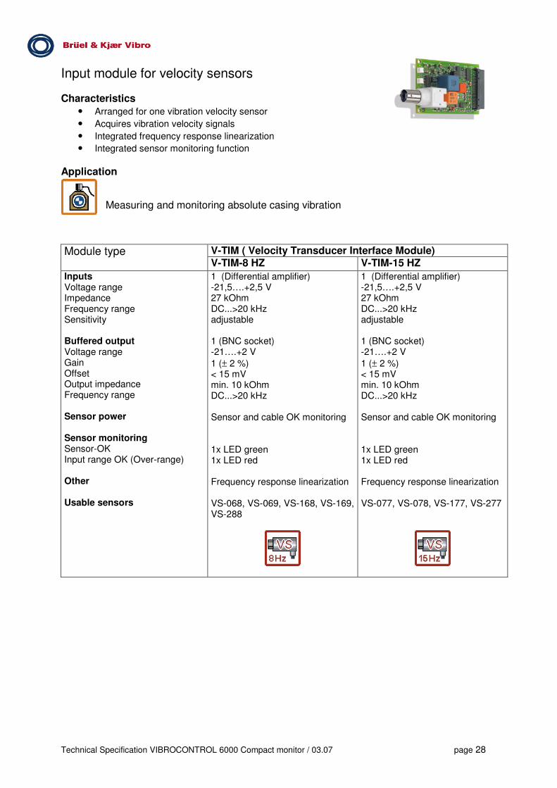
Input module for velocity sensors Characteristics
• Arranged for one vibration velocity sensor • Acquires vibration velocity signals • Integrated frequency response linearization • Integrated sensor monitoring function
Application
Measuring and monitoring absolute casing vibration
V-TIM ( Velocity Transducer Interface Module) Module type
V-TIM-8 HZ V-TIM-15 HZ
Inputs Voltage range Impedance Frequency range Sensitivity Buffered output Voltage range Gain Offset Output impedance Frequency range Sensor power Sensor monitoring Sensor-OK Input range OK (Over-range) Other Usable sensors
1 (Differential amplifier) -21,5….+2,5 V 27 kOhm DC...>20 kHz adjustable 1 (BNC socket) -21….+2 V
1 (± 2 %) < 15 mV min. 10 kOhm DC...>20 kHz Sensor and cable OK monitoring 1x LED green 1x LED red Frequency response linearization VS-068, VS-069, VS-168, VS-169, VS-288
1 (Differential amplifier) -21,5….+2,5 V 27 kOhm DC...>20 kHz adjustable 1 (BNC socket) -21….+2 V
1 (± 2 %) < 15 mV min. 10 kOhm DC...>20 kHz Sensor and cable OK monitoring 1x LED green 1x LED red Frequency response linearization VS-077, VS-078, VS-177, VS-277

Technical Specification VIBROCONTROL 6000 Compact monitor / 03.07 page 29
Input module for displacement sensors Characteristics
• Arranged for one non-contacting displacement sensor • Acquires displacement and vibration signals • Acquires phase-reference signals (impulse signals) • Provides power to the sensor • Integrated sensor monitoring function
Application Measuring and monitoring relative shaft vibration (2 Modules per measuring plane required) Measuring and monitoring axial shaft position
Measuring and monitoring radial shaft position (2 Modules per measuring plane required) Measuring and monitoring speed (under preparation)
Module type D-TIM ( Displacement Transducer Interface Module)
Inputs Voltage range Impedance Frequency range Sensitivity Buffered output Voltage range Gain Offset Output impedance Frequency range Sensor power Sensor monitoring Sensor-OK Input range OK (Over-range) Usable sensors
1 (Differential amplifier) -21,5….+2,5 V 200 kOhm DC...50 kHz adjustable 1 (BNC socket) -21….+2 V
1 (± 2 %) < 15 mV min. 10 kOhm DC...>20 kHz Voltage –24V DC / max. 30mA 1x LED green 1x LED red Displacement sensors of the series SD, IN and DS
For displacement and vibration measurement As reference sensor (speed sensor)

Technical Specification VIBROCONTROL 6000 Compact monitor / 03.07 page 30
Input module for current and voltage signals Characteristics
• 2 signal inputs • Acquires quasi-static current and voltage signals • Acquires dynamic voltage signals • Acquires phase-reference signals (impulse signals) • Integrated signal monitoring function
Application
Measuring and monitoring process values and quasi-static signals (current and voltage)
Measuring and monitoring dynamic voltage signals
Measuring and monitoring speed (under preparation)
Module type GP-TIM (2-ch.) (General Purpose Transducer Interface Module)
Inputs Voltage range / Impedance Frequency range Current input range Current signal load Sensitivity Signal monitoring Input OK (Overload) Possible input signals
2 (Differential amplifiers) -15….+15 V / 200 kOhm DC...50 kHz -30...+30 mA 100 Ohm adjustable 1x LED green per channel
0/4...20mA current signals 0/2...10V voltage signals User-defined voltage signals -15...+15V
Trigger signals -15...+15V

Technical Specification VIBROCONTROL 6000 Compact monitor / 03.07 page 31
Conditioning module for BCU (Bearing Condition Unit) Characteristics
• 2 Signal inputs from adjacent input modules • BCU signal processing • Integrated signal monitoring function • Only in combination with one or two A-TIM input modules*
Application Measuring and monitoring rolling-element bearing condition
Module type BCU-CON (2-ch.); (BCU Conditioning Module)
Inputs Signal processing Signal filtering Signal detection Signal output Signal monitoring Input range OK (Over-range)
2 (from adjacent input modules) 15...60 kHz Peak detector Instantaneous value of BCU 1x LED red per channel
The BCU-CON module occupies the socket of one input module. Together with two A-SIM modules this automatically limits the number of channels of the VIBROCONTROL 6000 Compact monitor to 2 channels.

Technical Specification VIBROCONTROL 6000 Compact monitor / 03.07 page 32
Relay output module Characteristics
• 2 potential-free output relays Application
Alarming and event signalling to peripheral equipment
Module type Relay-Out (2-ch.)
No. of output relay Relay type Switching mode Time delay Electrical data Nominal operating voltage Minimum voltage Maximum current load Minimum current Operating status display
2, potential-free Change-over, mono-stable Normally energised and normally de-energised (programmable) freely programmable (0,00...99,99 s) 24…48 V DC 10 mV 500 mA 10 µA 1x LED green and 1x LED yellow/red per channel

Technical Specification VIBROCONTROL 6000 Compact monitor / 03.07 page 33
Output module for current and voltage signals Characteristics
• 2 galvanically isolated DC outputs, short-circuit proof
• Output of current signals (e.g. 4...20mA)
• Output of voltage signals (e.g. 0...10V)
• Programmable for linear and non-linear output signal curve
Application
Preparation of measured values as analogue signals for peripheral equipment
Module type DC-Out (2-ch.)
No. of DC outputs Reaction time Electrical data
Current output range Max. load
Voltage output range Min. output load
2, galvanically isolated, short-circuit proof 5 ms 4-20 mA or 0-20 mA 500 Ohm 0-10V or 2-10V or 0-5V 1 kOhm

Technical Specification VIBROCONTROL 6000 Compact monitor / 03.07 page 34
Optional accessories (not part of standard delivery)
VIBROCONTROL 6000 Compact monitor User terminal
Order code UT-100 Function Display Language support Operation Operating temperature Protection class Connection Delivered accessories
VIBROCONTROL 6000 Compact monitor local operation Display current measured value Display Logbook contents Change parameter settings (e.g. limit values) 2-line display ( 2x 16 characters) English, German and French Sealed-foil front panel with 5 buttons -20°C...+70°C IP 20 D-Sub-socket at the front panel of the VIBROCONTROL 6000 Compact monitor Fixed connecting cable, 2.5 m length Locking clip AC-4501 for DIN-rail mounting

Technical Specification VIBROCONTROL 6000 Compact monitor / 03.07 page 35
Protective housing for installing the VIBROCONTROL 6000 Compact monitor in an industrial environment Order code AC-2100/55 Ambient conditions Protection class Size Empty weight Colour
protective housing of sheet metal with window suitable for 1 piece VIBROCONTROL 6000 Compact monitor or for the installation of the network interface Industrial environment, Non-Ex IP55 400 mm x 200 mm x 155 mm appr. 7 kg RAL 7032
Order code AC-2100/66 Ambient conditions Protection class Size Empty weight Colour
protective housing of sheet metal suitable for 1 piece VIBROCONTROL 6000 Compact monitor or for the installation of the network interface Industrial environment, Non-Ex IP66, Nema 4, 12 & 13 400 mm x 200 mm x 125 mm appr. 4.3 kg RAL 7032

Technical Specification VIBROCONTROL 6000 Compact monitor / 03.07 page 36
Installation accessories
Order code AC-2600 Component set for cable shielding
for terminating and grounding of incoming sensor cable shields consisting of one common rail , clamps and spring-terminals Application: for installing the VIBROCONTROL 6000 Compact monitor in housings or cabinets without own shielding concept
AC-4500 Connector set for the VIBROCONTROL 6000 Compact monitor
AC-4501 Locking clip for the Compact monitor User terminal For mounting the User terminal on a 35 mm rail
Digital Communication Order code AC-5003 Converter SCI-RS232 for DIN-rail mounting
AC-5004 2-Port Ethernet-Gateway for DIN-rail mounting
7131 OPC Data Access Server
SIMS Compact monitor
SCI (2 Mbit/s)
RS - 232(115 kbit/s)
Ethernet TCP/IP
orRS -4xx
Converter SCI - RS232
Gateway
VC-6000 Compact monitor
SCI (2 Mbit/s)
RS - 232(115 kbit/s)
Ethernet TCP/IP
orRS -4xx
Converter SCI - RS232
Gateway

Technical Specification VIBROCONTROL 6000 Compact monitor / 03.07 page 37
Sensors For detailed sensor information please consult our sensor catalogue
Accelerometers Order code AS-022 100 mV/g, Power –24 VDC, up to 125°C
5 m connecting cable, Steel protective cable conduit option
AS-030 100 mV/g, Power –24 VDC, up to 125°C, Fast-on connectors
AS-062/050/0 AS-062/100/0 AS-062/050/1
CCS sensor, 100 mV/g, up to 125°C, 5 m connecting cable Sensor with 10 m connecting cable Sensor with 5 m connecting cable and steel protective cable conduit
AS-070/001 AS-070/002
CCS sensor, 100 mV/g, up to 120°C, 10 m connecting cable CCS sensor, 100 mV/g, up to 120°C, 10 m connecting cable
AS-080/01 CCS sensor, 100 mV/g, up to 150°C, MIL-C-5015 2-pole
8325-A-0 8325-S-1-03-A-0100
CCS sensor, 100 mV/g, up to 125°C, MIL-C-5015 2-pole CCS sensor, 100 mV/g, up to 125°C, 10 m connecting cable Other cable lengths on enquiry
8327-A-0 8327-S-1-03-A-0100
CCS sensor, 10 mV/g, up to 125°C, MIL-C-5015 2-pole CCS sensor, 10 mV/g, up to 125°C, 10 m connecting cable Other cable lengths on enquiry
8331-A-0 8331-S-1-03-A-0100
CCS sensor, 100 mV/g, up to 125°C, MIL-C-5015 2-pole CCS sensor, 100 mV/g, up to 125°C, 10 m connecting cable Other cable lengths on enquiry
8332-A-0 8332-S-1-03-A-0100
CCS sensor, 10 mV/g, up to 125°C, MIL-C-5015 2-pole CCS sensor, 10 mV/g, up to 125°C, 10 m connecting cable Other cable lengths on enquiry
For high-temperature sensors, charge-amplifiers and sensors for Ex areas (see sensor catalogue) Installation accessories and connecting cable (see sensor catalogue)
Vibration velocity sensors Order code VS-068 100 mV/mm/s, horizontal measuring direction, 5 m connecting cable, steel
protective cable conduit
VS-069 100 mV/mm/s, vertical measuring direction, 5 m connecting cable, steel protective cable conduit
VS-077 75 mV/mm/s, hor./vert. measuring direction, 5 m connecting cable, steel protective cable conduit
VS-079 75 mV/mm/s, hor./vert. measuring direction, 5 m connecting cable, steel protective cable conduit, up to 200°C
Sensors for Ex areas, Installation accessories and connecting cable See catalogue VIBROSENSORS BV-P1001/3e
Displacement sensors See catalogue VIBROSENSORS BV-P1001/3e
Brüel & Kjaer Vibro reserves the right to change specifications and accessories without notice.
The current version of this document is available at
http://www.bkvibro.de or http://www.bkvibro.com


![Traceability and metrological assurance of the unity of ......(ISO 10816, ISO 7919, ISO 13374, ISO 13379, ISO 13380 , ISO 13381) [1-5] control rangeof operating frequenciesNPP equipment](https://cdn.vdocuments.net/doc/165x107/5e5b2946b77fa8412c11ebdc/traceability-and-metrological-assurance-of-the-unity-of-iso-10816-iso.jpg)
