FACULTY V
Mechanical Engineering & Transport
Systems
Institute of Land and Sea Transport Systems
Rail Vehicles Department
Prof. Dr.-Ing. Markus Hecht
Dipl.-Ing. Philipp Krause
TEL.: +49 (0)30 314 25388
FAX: +49 (0)30 314 22529
E-MAIL: [email protected]
Report
Final Report by the Bogies Task Force of the
Technical Innovation Circle for Rail Freight Transport
(TIS)
Status 13 March 2014
Technische Universität Berlin
Prof. Dr.-Ing. Markus Hecht
Berlin, 13 March 2014 Dipl.-Ing. Patrick Eschweiler
Dipl.-Ing. Philipp Krause

Report Technische Universität Berlin
Status: 13 March 2014 Rail Vehicles Department
2 / 25
Contents
I. List of Illustrations .................................................................................................................... 3
1. Summary ................................................................................................................................. 4
2. Introduction .............................................................................................................................. 5
3. Implementation model ............................................................................................................. 7
4. Technical and operational requirements .................................................................................. 8
4.1 Technical requirements for the bogie system as a whole ....................................................... 8
4.1.1 Notes ............................................................................................................................ 10
4.2 Technical requirements for the bogie frame module ............................................................ 12
4.2.1 Notes ............................................................................................................................ 13
4.3 Technical requirements for the brake system module .......................................................... 13
4.3.1 Notes ............................................................................................................................ 14
4.4 Technical requirements for the wheelset module ................................................................. 15
4.5 Technical requirements for the sensor system module ........................................................ 19
4.5.1 Notes ............................................................................................................................ 19
5. Approval processes required for a TSI bogie – Options A and B............................................ 20
6. Literature ............................................................................................................................... 22
ANNEX A ...................................................................................................................................... 23
Report Technische Universität Berlin
Status: 13 March 2014 Rail Vehicles Department
3 / 25
I. List of Illustrations
Figure 1: TIS Structure, [1] .............................................................................................................. 5
Figure 2: Structure of the Bogie Task Force .................................................................................... 6
Figure 3: Implementation model ...................................................................................................... 7

1. Summary
Bogies are a key cost factor in freight transport, not only because they have to be purchased and
maintained, but also in terms of reliability and operating procedures. With total process
optimisation in mind, the Bogies Task Force was requested by TIS, the Technical Innovation Circle
for Rail Freight Transport, to look into the technical requirements for bogies, and these have been
set out in the Final Report below.
The study focused on twin-axle bogies for freight wagons. The assumption throughout was a
maximum load per axle of 25 tonnes. As requirements are extremely diverse and annual mileage,
in particular, will continue to vary widely, a modular concept was devised to enable as many carry-
over parts as possible while still providing flexibility when needed.
In using this modular approach to draw up concrete directives, the authors differentiated between
two basic options, A and B. Option A allows for basic innovations to be implemented in the existing
fleet and in retrofits, while Option B is designed for new vehicle generations and puts all five “L”
criteria to their full innovative use.
The various modules and their combinations are to be analysed in the light of the target impacts of
the 5L approach and assessed in terms of the beneficial effects they can generate for the main
players in rail freight transport.
The requirements identified are intended, firstly, to assist the manufacturers of freight car bogies by
offering a working platform for further implementation and, secondly, to facilitate the definition of a
requirement profile for ordering a specific vehicle. The findings also provide a basis for ongoing
discussion with the TIS cross-disciplinary group on an LCC/earnings-adjusted model.
Prof. Dr.-Ing. Markus Hecht Dipl.-Ing. Philipp Krause Dipl.-Ing Patrick Eschweiler
Report Technische Universität Berlin
Status: 13 March 2014 Rail Vehicles Department
5 / 25
2. Introduction
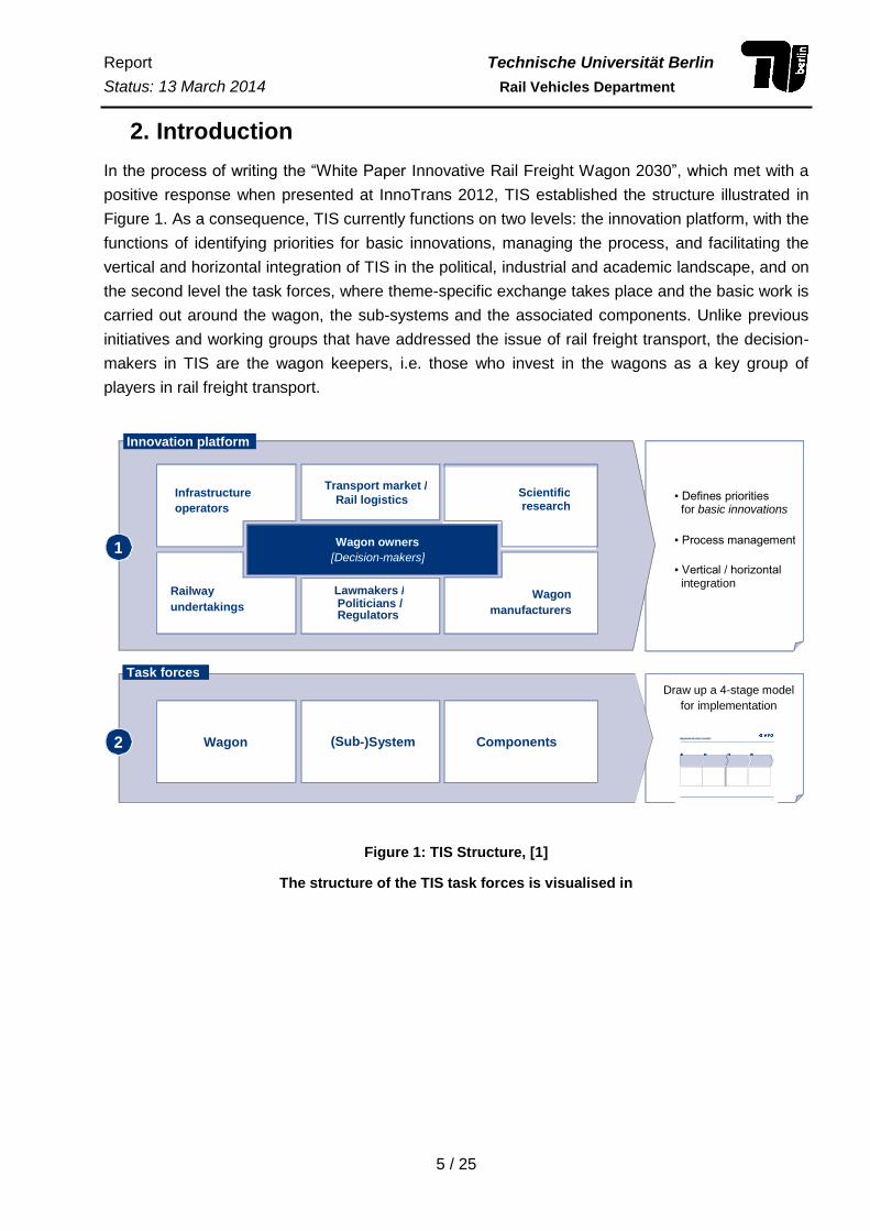
In the process of writing the “White Paper Innovative Rail Freight Wagon 2030”, which met with a
positive response when presented at InnoTrans 2012, TIS established the structure illustrated in
Figure 1. As a consequence, TIS currently functions on two levels: the innovation platform, with the
functions of identifying priorities for basic innovations, managing the process, and facilitating the
vertical and horizontal integration of TIS in the political, industrial and academic landscape, and on
the second level the task forces, where theme-specific exchange takes place and the basic work is
carried out around the wagon, the sub-systems and the associated components. Unlike previous
initiatives and working groups that have addressed the issue of rail freight transport, the decision-
makers in TIS are the wagon keepers, i.e. those who invest in the wagons as a key group of
players in rail freight transport.
Figure 1: TIS Structure, [1]
The structure of the TIS task forces is visualised in
Wagon (Sub -)System Components
Innovation platform
Task forces
1
2
Wagon owners [Decision-makers]
Transport market / Rail logistics
Lawmakers / Politicians / Regulators
Wagon
manufacturers
Scientific research
Railway
undertakings
Infrastructure
operators ▪ Defines priorities
for basic innovations
▪ Process management
▪ Vertical / horizontal integration
Draw up a 4-stage model
for implementation
Implementation model
1 2 3 4
13
Report Technische Universität Berlin
Status: 13 March 2014 Rail Vehicles Department
6 / 25
4
Bogie Task Force
2
Transport market / Rail logistics ▪ Technical/operational
requirements for the future bogie
▪ LCC models, transfer models, migration models
▪ Financing/Funding
Project goals
Wagon keepers
• VTG AG • SBB Cargo
• RCA
Wagon manufacturers
• Waggonbau Graaff • DB Waggonbau Niesky
Scientific research • TU Berlin
Railway undertakings • DB Schenker Rail
• SBB Cargo • RCA
Infrastructure operator • DB Netze
▪ Licensing (legal framework)
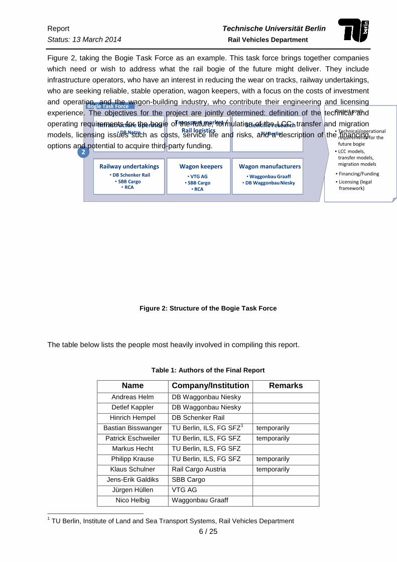
Figure 2, taking the Bogie Task Force as an example. This task force brings together companies
which need or wish to address what the rail bogie of the future might deliver. They include
infrastructure operators, who have an interest in reducing the wear on tracks, railway undertakings,
who are seeking reliable, stable operation, wagon keepers, with a focus on the costs of investment
and operation, and the wagon-building industry, who contribute their engineering and licensing
experience. The objectives for the project are jointly determined: definition of the technical and
operating requirements for the bogie of the future, formulation of the LCC, transfer and migration
models, licensing issues such as costs, service life and risks, and a description of the financing
options and potential to acquire third-party funding.
Figure 2: Structure of the Bogie Task Force
The table below lists the people most heavily involved in compiling this report.
Table 1: Authors of the Final Report
Name Company/Institution Remarks
Andreas Helm DB Waggonbau Niesky
Detlef Kappler DB Waggonbau Niesky
Hinrich Hempel DB Schenker Rail
Bastian Bisswanger TU Berlin, ILS, FG SFZ1 temporarily
Patrick Eschweiler TU Berlin, ILS, FG SFZ temporarily
Markus Hecht TU Berlin, ILS, FG SFZ
Philipp Krause TU Berlin, ILS, FG SFZ temporarily
Klaus Schulner Rail Cargo Austria temporarily
Jens-Erik Galdiks SBB Cargo
Jürgen Hüllen VTG AG
Nico Helbig Waggonbau Graaff
1 TU Berlin, Institute of Land and Sea Transport Systems, Rail Vehicles Department
Report Technische Universität Berlin
Status: 13 March 2014 Rail Vehicles Department
7 / 25
Report Technische Universität Berlin
Status: 13 March 2014 Railway Vehicles Department
8 / 25
5
Agree / Determine a framework of technical & operational conditions
Review essential licensing processes
Review & ensure business case
Review potential and need for finance
1 2 3 4
Framework requirements ensure innovations will suit the markets
Licensing requirements must enable innovations ▪ newbuilds ▪ conversions
Innovations must present overall profitability for wagon keepers / investors ▪ LCC models ▪ transfer models
▪ migration models
Use & develop suitable national & European finance & funding mechanisms
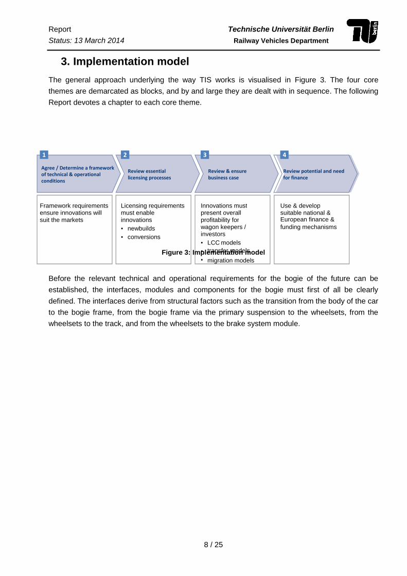
3. Implementation model
The general approach underlying the way TIS works is visualised in Figure 3. The four core
themes are demarcated as blocks, and by and large they are dealt with in sequence. The following
Report devotes a chapter to each core theme.
Figure 3: Implementation model
Before the relevant technical and operational requirements for the bogie of the future can be
established, the interfaces, modules and components for the bogie must first of all be clearly
defined. The interfaces derive from structural factors such as the transition from the body of the car
to the bogie frame, from the bogie frame via the primary suspension to the wheelsets, from the
wheelsets to the track, and from the wheelsets to the brake system module.
Report Technische Universität Berlin
Status: 13 March 2014 Railway Vehicles Department
9 / 25
4. Technical and operational requirements
There is often a conflict of interest between technical and operational requirements. The solutions
with the greatest potential in terms of noise reduction and lightweight design, for example, do not
comply sufficiently with all railway standards, and in some cases they call for a new system,
because future noise abatement targets in particular cannot be achieved by continuing along the
same path of development. That explains why the technical requirements for basic innovations had
to be broken down throughout into two options (A and B).
Option A:
- Basic innovations that can be incorporated into the existing fleet and new wagons based on the
same designs
- Improvement to at least one of the five “L” factors
Option B:
- New bogie designs for a new generation of rolling stock, with improvements to more than one
of the five “L” factors
- Must be compatible with the current operating system (CW identifier)
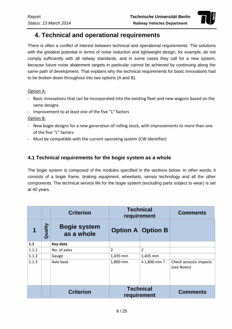
4.1 Technical requirements for the bogie system as a whole
The bogie system is composed of the modules specified in the sections below. In other words, it
consists of a bogie frame, braking equipment, wheelsets, sensor technology and all the other
components. The technical service life for the bogie system (excluding parts subject to wear) is set
at 40 years.
Criterion Technical
requirement Comments
1
Qu
ali
ty
Bogie system as a whole
Option A Option B
1.1 Key data
1.1.1 No. of axles 2 2
1.1.2 Gauge 1,435 mm 1,435 mm
1.1.3 Axle base 1,800 mm ≠ 1,800 mm ? Check acoustic impacts (see Notes)
Criterion Technical
requirement Comments

Report Technische Universität Berlin
Status: 13 March 2014 Rail Vehicles Department
10 / 25
Q
ua
lity
Bogie system
as a whole Option
A Option B
1.2 Axle load
1.2.1 R2 Admissible axle load ≥ 22.5 t3 25 t
1.3 Speed
1.3.1 R Permissible running speed 120 km/h 120 km/h
1.3.2 R Permissible braking speed in standard version
100 km/h 100 km/h
1.3.3 R Permissible braking speed for SS class wagons
120 km/h 120 km/h
1.3.4 P4 Permissible running speed5 160 km/h 160 km/h
1.4 Weight 1.4.1 R Less weight than reference
bogie Y25 1xBGU without end carriage with identical braking equipment (not counting wheelset weight)
x6 x
1.5 Compatibility / Installation
1.5.1 R Joined to car body Pivot acc. to UIC 510-1, Annexes 8 and 9
no spec
1.5.2 R Lateral support on body Lateral support acc. to UIC 510-1, Annexes 8 and 9
no spec
1.5.3 R Envelope Envelope acc. to UIC 510-1, Annex 11a
Envelope acc. to UIC 510-1, Annex 11a
1.5.4 R Vehicle gauge Compliant with UIC 505-1
Compliant with UIC 505-1
1.5.5 R Compatible with automatic coupling
Envelope acc. to UIC 510-1, Annex 11a
Envelope acc. to UIC 510-1, Annex 11a
Criterion Technical
requirement Comments
Qu
ali
ty
Bogie system as a whole
Option A
Option B
2 F … Required
3 25 t. wheelset load also preferable for Option A depending on the implications for development and design
costs. 4 W … Preference
5 Speed of 160 km/h depending on the implications for development and design costs.
6 x … is a key criterion

Report Technische Universität Berlin
Status: 13 March 2014 Rail Vehicles Department
11 / 25
1.6 Noise
1.6.1 R Wagon complies with TSI Noise Limits expected by 2016 (reference bogie Y25 1xBGU without end carriage with composite pads)
-2 dB comp. with current limit for new
wagons7
-4 dB comp. with current limit for new wagons
1.7 Running characteristics
1.7.1 R Improved running qualities with positive impact on maintenance8
x x Demonstrably less wear on wheels, better ride
1.7.2 R Improved running qualities with positive impact on infrastructure
x x Measurement criteria to be defined by infrastructure operators
1.7.3 R Standard for running characteristics is observed
EN 14363 EN 14363
1.7.4 R Minimum curve radius to be taken by the wagon
35 m9 75 m
1.8 Wear 1.8.1 R Less wear on wheels/ flanges
compared with Y25 x x Evidence required
1.9 Certification 1.9.1 R Requisite TSI Wagon
component certification (valid from 1 January 2014)
x x
1.10 Repair and maintenance
1.10.1 R Service life for all components At least 600,000 km, At least 6 years
At least 600,000 km, At least 6 years
1.10.2 R Maintenance of all components must be feasible independently of manufacturers
x x
1.11 In-track operations
1.11.1 R Full technical wagon inspection must be feasible under operating conditions (in track)
x x
1.12 Other
1.12.1 R Load indicator (total load, wheel load, load distribution)
x x Visible on the wagon without optical aid
4.1.1 Notes
Criterion 1.1.3: Axle base
Discussions were held about altering the axle base compared with the current Y25 bogie
axle base of 1,800 mm.
7 Only to be implemented in new rolling stock, not existing fleet.
8 Resonance behaviour and its noise impacts taken into account.
9 Similar envelope to Y25
Report Technische Universität Berlin
Status: 13 March 2014 Rail Vehicles Department
12 / 25
The underlying idea was that in future the axle base should not be designed around a
whole-number multiple of sleeper intervals (currently: 600mm to 1,800 mm), with a few to
stimulating less vibration in the body of the car.
Altering the axle base would produce the following advantages
smoother running (if the axles are placed further apart)
less body vibration, although no concrete values have been demonstrated
possibly also less in-track maintenance
This would be offset by the following disadvantages
bumpier running (if the axles are placed closer together)
The Y25 envelope and the installation space for the automatic central buffer
coupling are no longer observed if the axle base is lengthened. If the envelope is
exceeded, this measure cannot be combined with new bogies in existing vehicles or
if tried and tested wagon superstructures remain in use.
If wheelsets are spaced further apart, the bogie frame will be longer, increasing
mass.
Criterion 1.7.2: Improved running qualities with positive impact on infrastructure
Detailed studies still need to be carried out on this point. Initial approaches are:
indirect determination of running properties and wear via measurement of traction energy
requirement and systematic analysis of wheelset maintenance logs and measurement of
track wear.
Criterion 1.7.4: Minimum wagon curve radius
If the minimum wagon radius (i.e. the smallest radius the wagon can negotiate) is
increased, the bogie does not need to tilt so far. This permits a different kind of support for
the body (similar to passenger railcars, railway engines) and substantially enhances flux.
This saves considerable weight in the bogie and the body of the car.
However, these extensive changes means that the new bogie is incompatible with many
well established wagon designs, so that cars would have to be redesigned and new
approvals would be required.
Criterion 1.11.1: Full technical wagon inspection must be feasible under operating
conditions (in track)
Even wagons equipped with the new bogie will have to observe the future rules and be inspected
by the technician before the train sets off. That means ensuring that all safety-relevant bogie
components can be assessed. Conceptual design needs to factor in not only the traditional direct
visual inspection, but also indirect checks using sensor technology, remote indicators, scale
instruments, inspection glasses etc.
Report Technische Universität Berlin
Status: 13 March 2014 Rail Vehicles Department
13 / 25
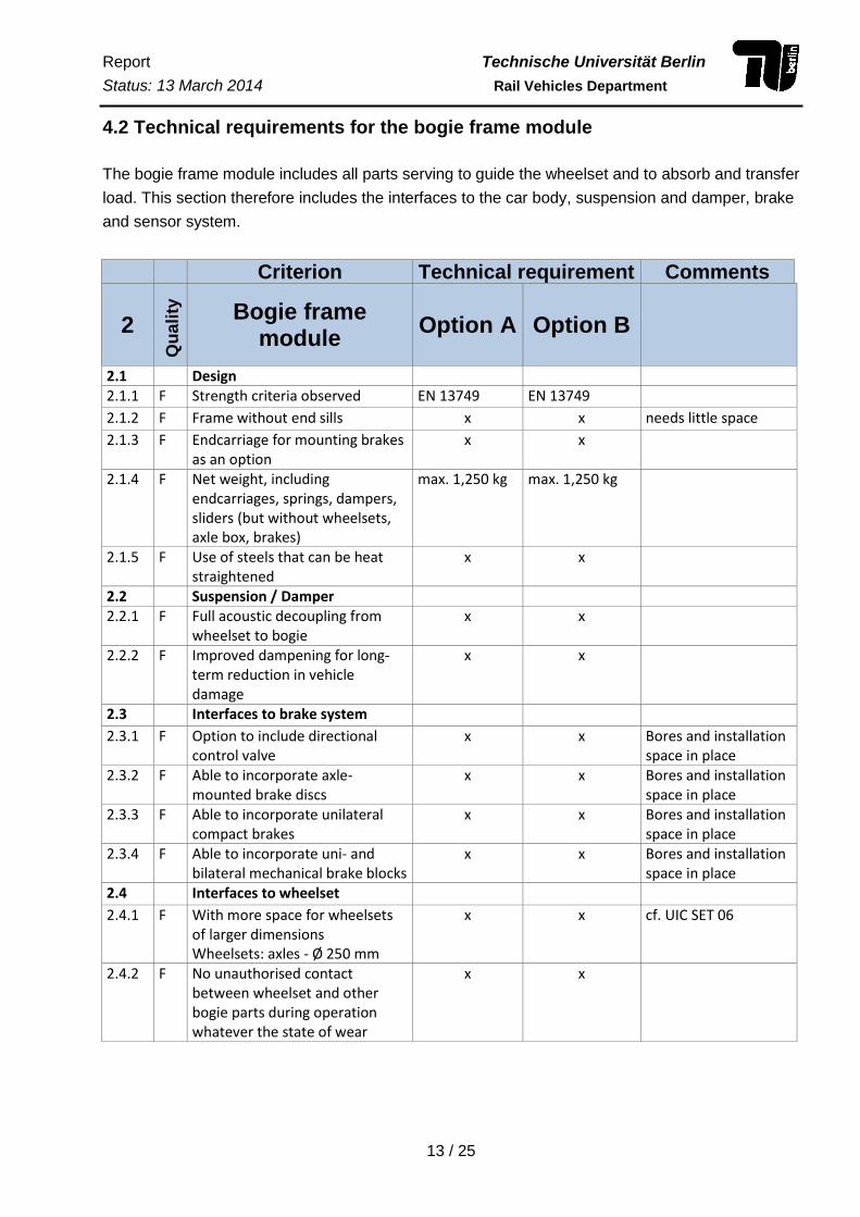
4.2 Technical requirements for the bogie frame module
The bogie frame module includes all parts serving to guide the wheelset and to absorb and transfer
load. This section therefore includes the interfaces to the car body, suspension and damper, brake
and sensor system.
Criterion Technical requirement Comments
2
Qu
ali
ty
Bogie frame module
Option A Option B
2.1 Design
2.1.1 F Strength criteria observed EN 13749 EN 13749
2.1.2 F Frame without end sills x x needs little space
2.1.3 F Endcarriage for mounting brakes as an option
x x
2.1.4 F Net weight, including endcarriages, springs, dampers, sliders (but without wheelsets, axle box, brakes)
max. 1,250 kg max. 1,250 kg
2.1.5 F Use of steels that can be heat straightened
x x
2.2 Suspension / Damper 2.2.1 F Full acoustic decoupling from
wheelset to bogie x x
2.2.2 F Improved dampening for long-term reduction in vehicle damage
x x
2.3 Interfaces to brake system
2.3.1 F Option to include directional control valve
x x Bores and installation space in place
2.3.2 F Able to incorporate axle-mounted brake discs
x x Bores and installation space in place
2.3.3 F Able to incorporate unilateral compact brakes
x x Bores and installation space in place
2.3.4 F Able to incorporate uni- and bilateral mechanical brake blocks
x x Bores and installation space in place
2.4 Interfaces to wheelset
2.4.1 F With more space for wheelsets of larger dimensions Wheelsets: axles - Ø 250 mm
x x cf. UIC SET 06
2.4.2 F No unauthorised contact between wheelset and other bogie parts during operation whatever the state of wear
x x
Report Technische Universität Berlin
Status: 13 March 2014 Rail Vehicles Department
14 / 25
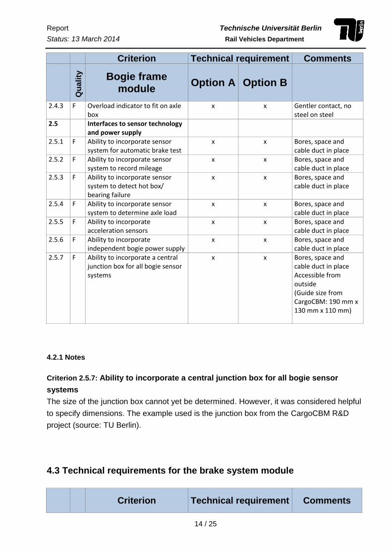
Criterion Technical requirement Comments
Q
ua
lity
Bogie frame
module Option A Option B
2.4.3 F Overload indicator to fit on axle box
x x Gentler contact, no steel on steel
2.5 Interfaces to sensor technology and power supply
2.5.1 F Ability to incorporate sensor system for automatic brake test
x x Bores, space and cable duct in place
2.5.2 F Ability to incorporate sensor system to record mileage
x x Bores, space and cable duct in place
2.5.3 F Ability to incorporate sensor system to detect hot box/ bearing failure
x x Bores, space and cable duct in place
2.5.4 F Ability to incorporate sensor system to determine axle load
x x Bores, space and cable duct in place
2.5.5 F Ability to incorporate acceleration sensors
x x Bores, space and cable duct in place
2.5.6 F Ability to incorporate independent bogie power supply
x x Bores, space and cable duct in place
2.5.7 F Ability to incorporate a central junction box for all bogie sensor systems
x x Bores, space and cable duct in place Accessible from outside (Guide size from CargoCBM: 190 mm x 130 mm x 110 mm)
4.2.1 Notes
Criterion 2.5.7: Ability to incorporate a central junction box for all bogie sensor
systems
The size of the junction box cannot yet be determined. However, it was considered helpful
to specify dimensions. The example used is the junction box from the CargoCBM R&D
project (source: TU Berlin).
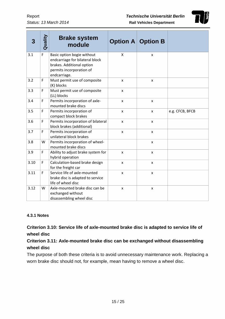
4.3 Technical requirements for the brake system module
Criterion Technical requirement Comments
Report Technische Universität Berlin
Status: 13 March 2014 Rail Vehicles Department
15 / 25
3 Q
ua
lity
Brake system
module Option A Option B
3.1 F Basic option bogie without endcarriage for bilateral block brakes. Additional option permits incorporation of endcarriage.
X x
3.2 F Must permit use of composite (K) blocks
x x
3.3 F Must permit use of composite (LL) blocks
x
3.4 F Permits incorporation of axle-mounted brake discs
x x
3.5 F Permits incorporation of compact block brakes
x x e.g. CFCB, BFCB
3.6 F Permits incorporation of bilateral block brakes (additional)
x x
3.7 F Permits incorporation of unilateral block brakes
x x
3.8 W Permits incorporation of wheel-mounted brake discs
x
3.9 F Ability to adjust brake system for hybrid operation
x x
3.10 F Calculation-based brake design for the freight car
x x
3.11 F Service life of axle-mounted brake disc is adapted to service life of wheel disc
x x
3.12 W Axle-mounted brake disc can be exchanged without disassembling wheel disc
x x
4.3.1 Notes
Criterion 3.10: Service life of axle-mounted brake disc is adapted to service life of
wheel disc
Criterion 3.11: Axle-mounted brake disc can be exchanged without disassembling
wheel disc
The purpose of both these criteria is to avoid unnecessary maintenance work. Replacing a
worn brake disc should not, for example, mean having to remove a wheel disc.
Report Technische Universität Berlin
Status: 13 March 2014 Rail Vehicles Department
16 / 25
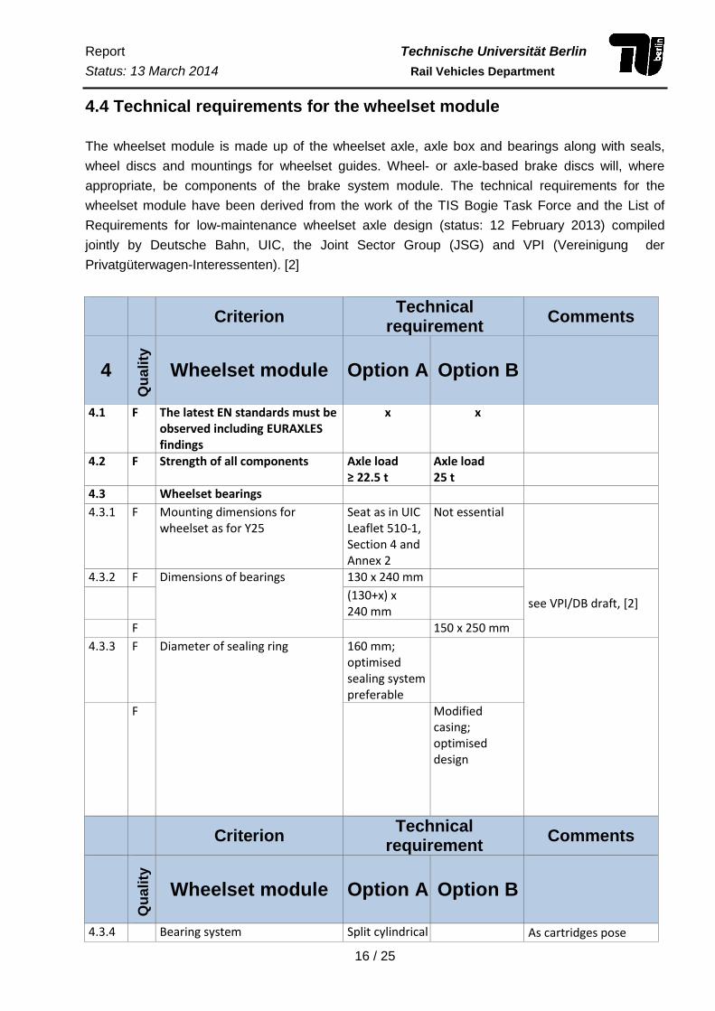
4.4 Technical requirements for the wheelset module
The wheelset module is made up of the wheelset axle, axle box and bearings along with seals,
wheel discs and mountings for wheelset guides. Wheel- or axle-based brake discs will, where
appropriate, be components of the brake system module. The technical requirements for the
wheelset module have been derived from the work of the TIS Bogie Task Force and the List of
Requirements for low-maintenance wheelset axle design (status: 12 February 2013) compiled
jointly by Deutsche Bahn, UIC, the Joint Sector Group (JSG) and VPI (Vereinigung der
Privatgüterwagen-Interessenten). [2]
Criterion
Technical requirement
Comments
4
Qu
ali
ty
Wheelset module Option A Option B
4.1 F The latest EN standards must be observed including EURAXLES findings
x x
4.2 F Strength of all components Axle load ≥ 22.5 t
Axle load 25 t
4.3 Wheelset bearings
4.3.1 F Mounting dimensions for wheelset as for Y25
Seat as in UIC Leaflet 510-1, Section 4 and Annex 2
Not essential
4.3.2 F Dimensions of bearings 130 x 240 mm
see VPI/DB draft, [2] (130+x) x
240 mm
F 150 x 250 mm
4.3.3 F Diameter of sealing ring 160 mm; optimised sealing system preferable
F Modified casing; optimised design
Criterion Technical
requirement Comments
Qu
ali
ty
Wheelset module Option A Option B
4.3.4 Bearing system Split cylindrical As cartridges pose

Report Technische Universität Berlin
Status: 13 March 2014 Rail Vehicles Department
17 / 25
roller bearings (if necessary caulked or mounted in cartridge)
disadvantages for maintenance, split cylindrical roller bearings are preferable
4.3.5 Long shaft journal 191 mm established
217 mm established
4.3.6 F Centre-to-centre spacing on the axle
2000 mm Check inner bearings
4.3.7 F No treatment for shaft journal (e.g. molybdenum coating)
x x uneconomic
4.4 Locks
4.4.1 W Axle bolts Replace 3 x M20 by optimised option: 4 x M16 longer thread reach longer grip
Needs further examination
4.4.2 F No locknuts x x Less efficient, harder to perform NDT on shaft end
4.5 F Wheelset axle material EA1N established, widely used material
4.6 Wheel seating
4.6.1 F Standardised diameter taking account of dimension specs
x x Compatibility of wheels from different manufacturers only ensured by standardised interface Simpler approval
4.6.2 F Same position as for 25 t wheelset axle (BA 302): Distance reference plane – outer edge: 58 + 1 mm Distance reference plane – inner edge: 238 - 1mm
x x Compatibility of wheels from different manufacturers only ensured by standardised interface Simpler approval
4.6.3
Geometry must respect shorter length of seat in maintenance
x x
Criterion Technical
requirement Comments
Qu
ali
ty
Wheelset module Option A Option B
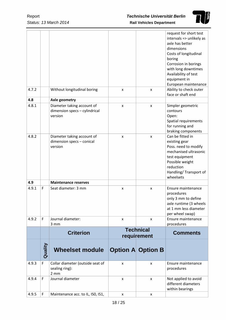
4.7 Longitudinal bores
4.7.1 With 30 mm longitudinal boring x x Easier to check Weight advantage Open: general NSA
Report Technische Universität Berlin
Status: 13 March 2014 Rail Vehicles Department
18 / 25
request for short test intervals => unlikely as axle has better dimensions Costs of longitudinal boring Corrosion in borings with long downtimes Availability of test equipment in European maintenance
4.7.2 Without longitudinal boring x x Ability to check outer face or shaft end
4.8 Axle geometry
4.8.1 Diameter taking account of dimension specs – cylindrical version
x x Simpler geometric contours Open: Spatial requirements for running and braking components
4.8.2 Diameter taking account of dimension specs – conical version
x x Can be fitted in existing gear Poss. need to modify mechanised ultrasonic test equipment Possible weight reduction Handling/ Transport of wheelsets
4.9 Maintenance reserves
4.9.1 F Seat diameter: 3 mm x x Ensure maintenance procedures only 3 mm to define axle runtime (3 wheels at 1 mm less diameter per wheel swap)
4.9.2 F Journal diameter: 3 mm
x x Ensure maintenance procedures
Criterion Technical
requirement Comments
Qu
ali
ty
Wheelset module Option A Option B
4.9.3 F Collar diameter (outside seat of sealing ring): 2 mm
x x Ensure maintenance procedures
4.9.4 F Journal diameter x x Not applied to avoid different diameters within bearings
4.9.5 F Maintenance acc. to IL, IS0, IS1, x x
Report Technische Universität Berlin
Status: 13 March 2014 Rail Vehicles Department
19 / 25
IS2 or similar must be feasible with existing refurbishing equipment and processes
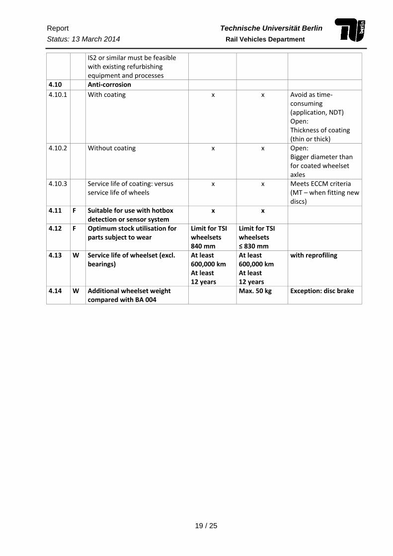
4.10 Anti-corrosion
4.10.1 With coating x x Avoid as time-consuming (application, NDT) Open: Thickness of coating (thin or thick)
4.10.2 Without coating x x Open: Bigger diameter than for coated wheelset axles
4.10.3 Service life of coating: versus service life of wheels
x x Meets ECCM criteria (MT – when fitting new discs)
4.11 F Suitable for use with hotbox detection or sensor system
x x
4.12 F Optimum stock utilisation for parts subject to wear
Limit for TSI wheelsets 840 mm
Limit for TSI wheelsets ≤ 830 mm
4.13 W Service life of wheelset (excl. bearings)
At least 600,000 km At least 12 years
At least 600,000 km At least 12 years
with reprofiling
4.14 W Additional wheelset weight compared with BA 004
Max. 50 kg Exception: disc brake
Report Technische Universität Berlin
Status: 13 March 2014 Rail Vehicles Department
20 / 25
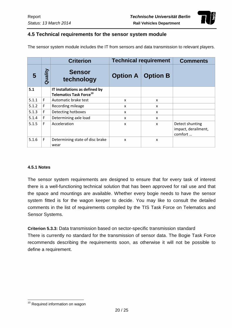
4.5 Technical requirements for the sensor system module
The sensor system module includes the IT from sensors and data transmission to relevant players.
Criterion Technical requirement Comments
5
Qu
ali
ty
Sensor technology
Option A Option B
5.1 IT installations as defined by Telematics Task Force10
5.1.1 F Automatic brake test x x
5.1.2 F Recording mileage x x
5.1.3 F Detecting hotboxes x x
5.1.4 F Determining axle load x x
5.1.5 F Acceleration x x Detect shunting impact, derailment, comfort …
5.1.6 F Determining state of disc brake wear
x x
4.5.1 Notes
The sensor system requirements are designed to ensure that for every task of interest
there is a well-functioning technical solution that has been approved for rail use and that
the space and mountings are available. Whether every bogie needs to have the sensor
system fitted is for the wagon keeper to decide. You may like to consult the detailed
comments in the list of requirements compiled by the TIS Task Force on Telematics and
Sensor Systems.
Criterion 5.3.3: Data transmission based on sector-specific transmission standard
There is currently no standard for the transmission of sensor data. The Bogie Task Force
recommends describing the requirements soon, as otherwise it will not be possible to
define a requirement.
10
Required information on wagon

Report Technische Universität Berlin
Status: 13 March 2014 Rail Vehicles Department
21 / 25
5. Approval processes required for a TSI bogie – Options A and B
Table 2: Certification for Bogie Option A in line with TSI WAG 08/57-ST17 Version EN03 of 27 June 2012
Item Bogie-specific
Wagon- specific
Measure TSI WAG Applicable standards
Time required (estimate)
Risk
1 X Bogie certification §6.1.2 (Conformity assessment procedures)
Modules CB+CD 6 weeks Incurred within respective tests
2 X Static and fatigue tests §4.2.3.6.1 (Structural design of bogie frame)
EN13749 16 weeks Cracks in bogie frame. Design needs modifying. Operational tests must be repeated. More time and greater cost
3 X Assessment of running behaviour and stationary tests (Assumption: test vehicles are available)
§4.2.3.5 (Running safety) §4.2.3.5.1 (Safety against derailment running on twisted track) §4.2.3.5.2 (Running dynamic behaviour) §4.2.3.6 (Running gear)
EN14363 prEN15839
12 weeks Running behaviour does not meet the requirements set out in the standards. Design needs modifying. Operational tests must be repeated. More time and greater cost
4 X Operational tests (on track) EN13479 52 weeks Damage or greater wear. Design needs modifying. Operational tests must be repeated. More time and greater cost
5 X Use of bogie in freight wagon certifications
PrEN16235 - Comment, for exemption from test drives observe conditions in PrEN16235

Report Technische Universität Berlin
Status: 13 March 2014 Rail Vehicles Department
22 / 25
Modules
Item Bogie-specific
Wagon- specific
Measure TSI WAG Applicable standards
Time required (estimate)
Risk
6 X Wheelset (Interoperability component subject to TSI)
§4.2.3.6.2 (Characteristics of wheelsets)
EN13260 - No risk, wheelset is approved and meets the requirements of TSI WAG
7 X Wheel disc/Monobloc Interoperability component subject to TSI)
§4.2.3.6.3 (Characteristics of wheels)
EN13979-1 - No risk, wheel is approved and meets the requirements of TSI WAG
8 X Wheelset axle (Interoperability component subject to TSI)
§4.2.3.6.4 (Characteristics of axles)
EN13103 - No risk, axle is approved and meets the requirements of TSI WAG
9 X Springs EN13913 not clear11
10 X Damper EN13802 not clear7
11 X Bearings EN12080 not clear7
12 X Grease EN12080 not clear7
13 X Housing §4.2.3.6.5 (Axle boxes / bearings)
EN12082 + EN13749
not clear7
14 X Brake §4.2.4 (Brake) - No risk, brake is approved and meets the requirements of TSI WAG
Noise
15 X Nose measurement: Vehicles are available for testing)
TSI Noise 2 weeks Bogie fails to meet desirable noise level.
Time required from full submission of documents and provision of test vehicles
36 weeks
(without operational testing under Item 4)
11
Data to be supplied by the manufacturer
Report Technische Universität Berlin
Status: 13 March 2014 Rail Vehicles Department
23 / 25
6. Literature
[1] R. König and M. Hecht, White Paper Innovative Rail Freight Wagon 2030, Dresden, 2012.
[2] DB, UIC, JSG, VPI, “Anforderungskatalog an eine neue instandhaltungsarme
Radsatzwellenkonstruktion,” 2013.
[3] J. Hüllen, “Perspektiven des Schienengüterverkehrs aus Sicht eines Güterwagenhalters /-
vermieters,” ZEV Rail, pp. 50-54, 2013.
[4] M. Hecht, “Maßnahmen für ein gesundes wirtschaftliches Wachstum des
Schienengüterverkehrs,” Vienna, 2012.
[5] J. Hüllen, “Definition von Innovationsvarianten im Rahmen von TIS,” slide, TIS meeting in
Hamburg, status 13 March 2013.
[6] J. Hüllen, “Matrix für LCC-/Ertragswertmodelle,” slide, TIS meeting in Hamburg, status
13 March 2013.
Report Technische Universität Berlin
Status: 13 March 2014 Rail Vehicles Department
24 / 25
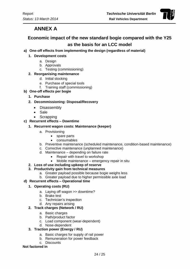
ANNEX A
Economic impact of the new standard bogie compared with the Y25
as the basis for an LCC model
a) One-off effects from implementing the design (regardless of material)
1. Development costs
a. Design b. Approvals c. Testing (commissioning)
2. Reorganising maintenance
d. Initial stocking
e. Purchase of special tools f. Training staff (commissioning)
b) One-off effects per bogie
1. Purchase
2. Decommissioning: Disposal/Recovery
Disassembly
Sale
Scrapping c) Recurrent effects – Downtime
1. Recurrent wagon costs: Maintenance (keeper)
a. Provisioning
spare parts
consumables b. Preventive maintenance (scheduled maintenance, condition-based maintenance) c. Corrective maintenance (unplanned maintenance) d. Maintenance – depending on failure rate
Repair with travel to workshop
Mobile maintenance – emergency repair in situ 2. Loss of use including upkeep of reserve 3. Productivity gain from technical measures
a. Greater payload possible because bogie weighs less b. Greater payload due to higher permissible axle load
d) Recurrent effects – Operational time
1. Operating costs (RU)
a. Laying off wagon >> downtime? b. Brake test c. Technician’s inspection d. Any repairs arising
2. Track charges (Network / RU)
a. Basic charges b. Path/product factor c. Load component (wear-dependent) d. Nose-dependent
3. Traction power (Energy / RU)
a. Basic charges for supply of rail power b. Remuneration for power feedback c. Discounts
Not factored in

Report Technische Universität Berlin
Status: 13 March 2014 Rail Vehicles Department
25 / 25
Productivity gains from process enhancements: influences the entire logistics chain,
advantages can only derive from improving the total process
decisive cut in turnaround time (e.g. from 49 to 47 hours)
Methodology for LCC model
Definition and management of framework scenarios:
- reference route: track parameters (percentage of curves and gradients), associated
track charge and time zone (defining charges for railway power)
- train formation (n wagons)
- travelling speed and profile (calculations of consumption + possibly feedback)


