
www.ecn.nl
Technological possibilities for the separation of H2 from CO2
Jaap Vente
Symposium for Innovative CO2Membrane Separation Technology
Dai‐ichi Hotel, Tokyo (東京)28th of September 2012

Japan and the Netherlands

A long joint history
Japan‐Netherlands exchange in the Edo Period (www.ndl.go.jp/nichiran/)
Dejima Dutch Trading Post (出島 1641 – 1853)

Dejima in the Literature
• A very well written and recent novel
Netherlands in Japan today

Locations
Petten
Amsterdam
Eindhoven
Wieringerwerf
Beijing
Brussels

Mission:With and for the market, we develop knowledgeand technology that enable a transition to a sustainable energy system.

R&D fields
Energy Efficiency &
CCS
Policy Studies
EnergyEngineering
Environment
Wind Energy Solar Energy Biomass
H2 and separation technologies

Hydrogen production
• Annual production of H2
~70x106 metric tons or ~0.7x10¹² Nm3 and growing with ~ 7%/yr
• 50% is produced by steam reforming of methane• Often high purity is demanded
• need for the separation of H2 from CO2
(www.world‐nuclear.org/info/inf70.html)
Elements of the hydrogen economyH2 production plant (Praxair)

H2 – CO2 Separation Drivers
• Low cost high purity ‘green’ H2 with low CO2 food print
• De‐carbonized fuel
• CO2 as valuable feedstock
• Electricity production with Carbon Capture and Storage.

Pre-combustion capture
Selections to be made:
•Membranes vs. sorption•Separation Enhance Reactors vs. various unit operations
(integrated) (non‐integrated)•Hot vs. cold•H2 selective vs. CO2 selective
Pre‐combustion vs. post‐combustion.Where is the win?
•Always high P(CO2) so plenty of driving force! Up to 20 bar cf. < 0.2 bar in post‐combustion
•Similar about P(H2)

Solvents at low temperature
• Demonstration phase, maturing quickly
Selexol scrubbing Eagle project, J‐Power, KitakyushuFukuoka Prefecture, Japan
Physical solventCatch‐Up Vattenfall, Buggenum, Limburg, The Netherlands
MDEA scrubbing, Puertollano Plant, Elcogas, Spain

Sorbent at high temperature
• Integration with reaction Separation Enhanced Reactor.• Higher conversions at lower costs
• SEWGS• ECN – technology
• ALKASORB Stability >5000 cycles of loading and unloading
• Full process demonstrated at 20 kWth scale.

SEWGS Scale-up
caesar.ecn.nl

ECN leading in thin filmdense metal membranes

Demands on the membrane
Performance demands•High flux•High selectivity•Long lifetime
Operational restraints •High temperature (400°C and higher!)•Large pressure drop (Pfeed 20 – 40 bar, Pperm 1 – 5 bar)

Materials options
• High performance thin layers• High pressure drops support system• High temperature rule out polymers
Two basic designs for separation layer• Nanoporous: hybrid and ceramic • Dense metal
Two basic materials for support• Ceramic (Al2O3)• Metallic, stainless steel
Focus of today

H2 Transport in dense metal membranes
1. Bulk diffusion2. Adsorption of hydrogen molecules3. Dissociation into atoms4. Absorption of atoms5. Diffusion of atoms6. Recombination7. Desorption
CO2
H2OH2
H2 H2
H2
H
HH
H1
2
3 54 6
7
Pd alloy membrane
High pressure Low pressure
CO2
H2OH2
H2 H2
H2
H
HH
H1
2
3 54 6
7
Pd alloy membrane
High pressure Low pressure
Pressure exponent n
Layer thickness l
Activation energy EactH2 flux: JH2 = (PoH2/l).exp(-Eact/RT).(PH2fn-PH2p
n)
Temperature activated process

Manufacturing the dense metal membrane
Two distinct approaches
Electroless plating
Dalian Institute of Chemical Physics
Worcester Polytechnic Institute
Energy research Centre of the Netherlands
Magnetron sputtering
Southwest Research Institute
SINTEF

Sputtering route
(1) Magnetron sputtering on Si wafer
(2) Pull‐off alloy 2 μm thin foil
(3) Wrap around tubular support
(4) Membranes on 50cm length scale

Electroless plating route
(3) Sequential reduction and deposition of metal ions.
(4) Alloying step by heat treatment
(1) Support pore size reduction
(2) Seeding of support

Lab test module
• Single tube (~10 cm long)• ~40 cm2
• Hydrogen flow: 0.15 ‐ 1 Nm3/h• Up to 70 bars

Scaling up to pilot size

The Chieti plant in Italy
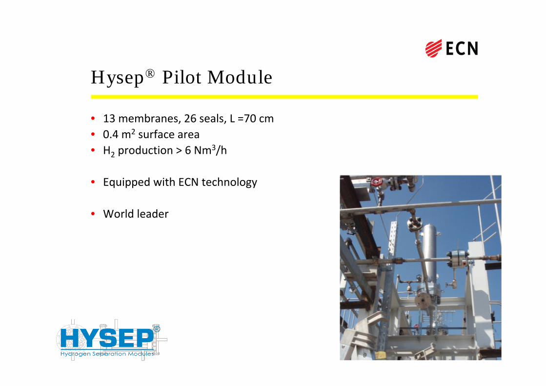
Hysep® Pilot Module
• 13 membranes, 26 seals, L =70 cm• 0.4 m2 surface area• H2 production > 6 Nm
3/h
• Equipped with ECN technology
• World leader

Simplified process scheme
• 2 stages of reaction and separation • 3 installed membrane module• 20 Nm3/h of hydrogen

First series of tests
CO2 feed ~ 6 ‐ 6.8 mol%CO feed ~ 1.1 ‐ 2.8 mol%H2Ofeed ~ 50‐ 57 mol%H2 feed ~ 26‐ 35 mol%CH4 feed ~ 6‐ 12 mol%
0 200 400 600 800 1000 12000.0
0.4
0.8
1.2
1.6
2.0
2.4
time [h]
0
1
2
3
4
5
6
7QH2 [mmol m-2*s-1*Pa-0.5] GHSV*103 [h-1]
Low pressure feed: 11 – 12 bar

Continued testing
0 200 400 600 800 1000 1200 14000.0
0.4
0.8
1.2
1.6
2.0
2.4QH2 [mmol m-2*s-1*Pa-0.5]
time [h]
Improved insulation

Operating variables
Variable QH2 H2 production H2 recovery H2 purity
GHSV ? ‐ ↓ ?
T reformer ‐ ↑ ↑ ↑
T membrane ↑ ↑ ↑ ↑
Pfeed ‐ ↑ ↑ ?
Ppermeate ‐ ↓ ↓ ?

Test results
• Successful scale up of a factor 100:from 40 to 4000cm2
• High H2 purity > 99.94%• Production up to 8 Nm3/h H2
(exceeding demands)
• Total test period of over 1500 hrs.
• Operating conditions:• T = 450 °C• P = 25 bar

Prototype HydrogenSeparation Modules
• To full length multi tubular (1/8 to 1/2m
2)• Up to 8 Nm3/h• Up to 25 bar
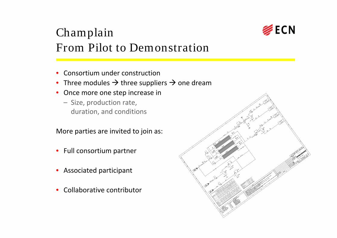
ChamplainFrom Pilot to Demonstration
• Consortium under construction• Three modules three suppliers one dream• Once more one step increase in– Size, production rate, duration, and conditions
More parties are invited to join as:
• Full consortium partner
• Associated participant
• Collaborative contributor

Acknowledgements
• Sintef: Thijs Peters, Marit Stange, Rune Bredesen
• Tecnimont KT: Annarita Salladini, Gaetano Iaquaniello
• My colleagues at ECN working on:SEWGS & HySep
Our sponsors
EU
NL


