
1
THE EXTENDED N2 METHOD IN SEISMIC DESIGN OF STEEL
FRAMES CONSIDERING SEMI-RIGID JOINTS
Paulina KROLO1, Mehmed CAUSEVIC2 and Mladen BULIC3
ABSTRACT
In this paper the nonlinear static seismic analysis of typical steel framed structure including the real joint
stiffness (instead of traditionally design with pinned or rigid joints) is presented.
In order to take into account the real joint behaviour in seismic analysis nonlinear analysis using
the finite element method of welded beam-to-column joint was carried out firstly. The beam-to-column
joints of analysed structure was chosen according to experimental tests. The results of finite element
analysis obtained in program Abaqus 6.12 are shown in the form of the moment-rotation curve.
Nonlinear moment-rotation curve will be idealized by tree-linear curve for the purpose of seismic
analysis.
The idea of this research is to show the influence of semi-rigid joints on the seismic effects for
moment resisting frames. The storey drifts and displacements obtained from seismic analysis for steel
frame including semi-rigid joints will be compared with results for steel frame with traditionally rigid
joins.
INTRODUCTION
The basic nonlinear static N2 method (Fajfar, 1999) which was implemented in Eurocode 8 was
constantly developing. The assumption that structure vibrates predominantly in the single mode is not
always fulfilled. A lot of work by several authors has been done and published worldwide extending the
simple pushover-based nonlinear static N2 method by taking into account either the influence of higher
modes in elevation or in plan, or in both plan end elevation, introducing the correction factors (Fajfar et
al., 2005, Causevic and Mitrovic 2011, Kreslin and Fajfar 2012). In the development of the extended
N2 method mainly reinforced concrete structures have been analysed.
Having in mind steel structures, beam-to-column joints of steel frames traditionally have been
modelled either as ideally pinned or perfectly rigid. Such approach does not show the real structural
behaviour.
In this paper the basic N2 method considering semi-rigid joints (instead of traditional design with
pinned or rigid joints) for steel structures is introduced. The idea of the influence of semi-rigid joints
on the seismic effects for steel moment resisting frames is illustrated in Fig.1. Joint stiffness will directly
influence the value of the fundamental period of structure which will be shown in further analysis.
Computational procedure was applied to the 3-storey steel framed structure which details were described
in the next chapter. The aim of this paper is to show results obtained from analysis (basic nonlinear static
N2 method) including the joint stiffness (rigid and semi-rigid) for displacements and storey drifts.
1 Research assistant, Faculty of Civil Engineering, Rijeka, Croatia, [email protected] 2 Professor, Faculty of Civil Engineering, Rijeka, Croatia, [email protected] 3 Assistant Professor, Faculty of Civil Engineering, Rijeka, Croatia, [email protected]
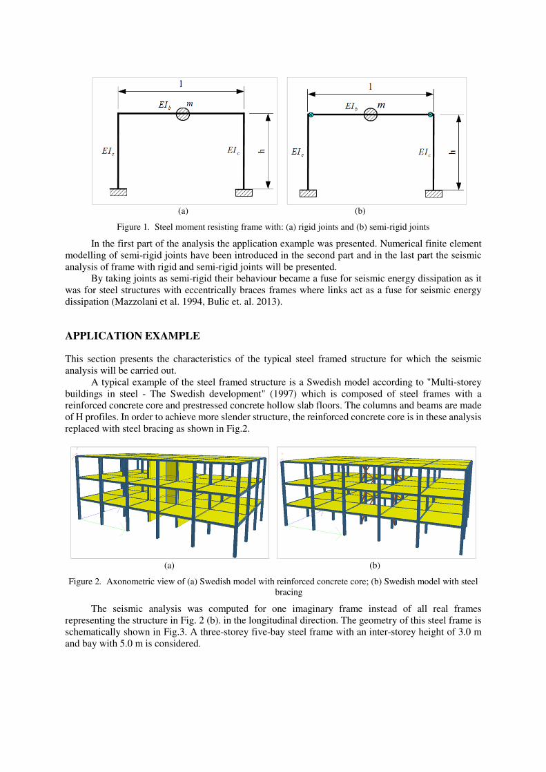
(a) (b)
Figure 1. Steel moment resisting frame with: (a) rigid joints and (b) semi-rigid joints
In the first part of the analysis the application example was presented. Numerical finite element
modelling of semi-rigid joints have been introduced in the second part and in the last part the seismic
analysis of frame with rigid and semi-rigid joints will be presented.
By taking joints as semi-rigid their behaviour became a fuse for seismic energy dissipation as it
was for steel structures with eccentrically braces frames where links act as a fuse for seismic energy
dissipation (Mazzolani et al. 1994, Bulic et. al. 2013).
APPLICATION EXAMPLE
This section presents the characteristics of the typical steel framed structure for which the seismic
analysis will be carried out.
A typical example of the steel framed structure is a Swedish model according to "Multi-storey
buildings in steel - The Swedish development" (1997) which is composed of steel frames with a
reinforced concrete core and prestressed concrete hollow slab floors. The columns and beams are made
of H profiles. In order to achieve more slender structure, the reinforced concrete core is in these analysis
replaced with steel bracing as shown in Fig.2.
(a) (b)
Figure 2. Axonometric view of (a) Swedish model with reinforced concrete core; (b) Swedish model with steel
bracing
The seismic analysis was computed for one imaginary frame instead of all real frames
representing the structure in Fig. 2 (b). in the longitudinal direction. The geometry of this steel frame is
schematically shown in Fig.3. A three-storey five-bay steel frame with an inter-storey height of 3.0 m
and bay with 5.0 m is considered.

Figure 3. Section trough the bracing system in the longitudinal direction (geometry and type of cross section)
This framed structure was analysed for two different cases. The first case uses the beam-to-
column joints as perfectly rigid (traditionally way). In this case the structure was calculated according
to “shear building” criteria (Chopra, 2012). The second case uses the beam-to-column joints as semi-
rigid (real joint behaviour). To reduce degrees of freedom of structure with semi-rigid joints, i. e. to
reduce the stiffness matrices order the static condensation procedure is performed (Chopra, 2012).
In order to take into account the real joint behaviour in seismic analysis, numerical simulation of
beam-to-column joints were carried out firstly.
FINITE ELEMENT MODELLING OF SEMI-RIGID JOINT
In this section the numerical finite element model of welded beam-to-column joints was presented.
Shape of the structural system of beam-to-column joint was chosen according to experimental tests
published by Skejic et al. (2008) and presented in the Fig. 4. (b)
(a) (b)
Figure 4. (a) Numerical finite element model of welded beam-to-column joint; (b) Shape of structural system
with boundary conditions and force position (dimension in mm)

Numerical model is based on a 3D materially nonlinear analysis using the finite element software
ABAQUS 6.12. Eight-node solid element C3D8R is used in the modelling of the beam, column and
welds. Detail of mesh and geometry are shown in the Fig. 4. (a) and (b). The finite element mesh was
more refined near the welds.
Two types of steel were considered, one for the beam and column and another for the welds.
Stress and strain response for the first material was taken to be nonlinear, and for the second to be
bilinear with Young`s modulus of 210000 MPa. Stress and strain relationship for nonlinear behaviour
is presented in the Fig. 5.
Figure 5. Stress-strain relationship for steel (nonlinear material)
The model was analysed for the effect of the bending moment. Bending moment was simulated
as a force applied at 1000 mm distance from the joint centre (or 850 mm from connection) which acts
on the upper side of the top flange of the beam. The load was modelled as 14 concentrated forces which
linear growth through the 22 steps. The total force value in the last step was 140 kN.
During the load action on the finite element model, deformations of beam and column were
occurring. Fig.6. shows the deformed finite element model.
Figure 6. Detail of deformed joint with finite element mesh
0
50
100
150
200
250
300
350
400
450
500
0 0,05 0,1 0,15 0,2 0,25 0,3 0,35
Str
ess
[MP
a]
Strain [-]
Beam and column material

Initial and deformed shape is shown in the Fig.7. Total rotation of joint (��� �) can be calculated
from vertical displacement � in the point beneath the load action as shown in Fig.8. Rotation of
connection was calculate from Eq.(1).
ϕ=Rot b - bel - Rot H1 (1)
where
Rot b is the total rotation of joint with elastic beam rotation bel which was calculating by Eq. (2),
bel is the elastic beam rotation which was calculate by Eq.(3),
Rot H1 is the column web panel rotation due to shear which was calculate by Eq.(4).
Rot b=δ1
850 (2)
where
δ1 is the vertical displacement in the point beneath the load action.
bel=FLF
2
2EIb (3)
where
F is the concentrated forces,
LF is the distance between load and external column surface which is connected for a beam,
E is the Young`s modulus,
Ib is the moment of inertia.
Rot H1=δ3-δ2
z (4)
where
δ2 and δ3 are horizontal displacement of column flanges due to shear action obtained from Fig. 7.
Figure 7. Initial and deformed shape of joint

Figure 8. Total rotation of joint
Final results are shown in the moment-rotation curve in Fig.9. (a). Initial rotational stiffness is
considered as 6465.5 kNm/rad. According to Eurocode 3 , here obtained stiffness of joint belongs to the
semi-rigid zone as shown in the Fig.9. (b). Nonlinear moment-rotation curve is idealised by three-linear
curve according to Wang et al. (2013) for the seismic analysis purpose.
(a) (b)
Figure 9. (a) Moment-rotation curve for semi-rigid joints and (b) classification of joints by stiffness
THE NONLINEAR STATIC SEISMIC ANALYSIS
In this section the impact of rigid and semi-rigid joints on the seismic behaviour of the steel
framed structure using a pushover based nonlinear static analysis approach (N2 method) is presented.
The seismic demand was computed with reference to the Eurocode 8 and basic characteristics of
seismic load are given in Table 1.
Table 1. Basic characteristics of seismic load
Elastic response spectrum Type 1
Ground type B
Peak ground acceleration �� = 0,254�
Damping ratio � = 4%
In the first case of frame analysis which uses the beam-to-column joints as perfectly rigid
(traditionally way), the structure was calculated according to “shear building” criteria (Chopra, 2012).
The second case of the frame analysis which uses the beam-to-column joints as semi-rigid in which the
rotation of stores are taken into account. To reduce degrees of freedom of structure with semi-rigid
0 2.5 103−
× 5 103−
× 7.5 103−
× 0.01
0
7.5 103
×
1.5 104
×
2.25 104
×
3 104
×
Upper limit for semi-rigid-joint
Lower limit for semi-rigid joint
Stiffness of semi-rigid joint
0102030405060708090
100110120130140150160
0 0,02 0,04 0,06 0,08
Mo
men
t [k
Nm
]
Rotation ϕ [rad]

joints, i. e. to reduce the stiffness matrices order the static condensation procedure is performed.
The obtained value of the fundamental period of steel frame with rigid and semi-rigid joints are given
in the following Table 2.
Table 2. Value of fundamental period
Type of frame Steel frame with rigid joints Steel frame with semi-rigid joints
Fundamental period T1 [s] 0.802 1.200
Fig.10. shows the position of fundamental period for steel frame on the elastic response spectrum
curve.
Figure 10. Fundamental period on the elastic response spectrum for steel frames with rigid joints (blue line) and
semi-rigid joints (green line)
The base shear-top storey displacement relationship (capacity curve) was obtained by gradually
increasing the lateral forces triangular distributed over the stores (pushover). Pushover analysis was
performed in SeismoStract software Version 6 on the imaginary frame representing the structure, Fig.11.
Figure 11. The steel frame structure with triangular distributed lateral force
0 0.2 0.4 0.6 0.8 1 1.2 1.4 1.6 1.8 2 2.2 2.4 2.6 2.8 30
0.1
0.2
0.3
0.4
0.5
0.6
0.7
0.8
0.9
1
Type 1 elastic response spectrum for ground type B (4% damping)
Fundamental period for steel frame with rigid joints
Fundamental period for steel frame with semi-rigid joints
T [s]
Sae
[g
]
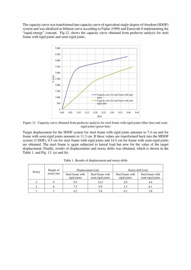
The capacity curve was transformed into capacity curve of equivalent single-degree-of-freedom (SDOF)
system and was idealized as bilinear curve according to Fajfar (1999) and Eurocode 8 implementing the
“equal-energy” concept. Fig.12. shows the capacity curve obtained from pushover analysis for steel
frame with rigid joints and semi-rigid joints.
Figure 12. Capacity curve obtained from pushover analysis for steel frame with rigid joints (blue line) and semi-
rigid joints (green line)
Target displacement for the SDOF system for steel frame with rigid joints amounts to 7.4 cm and for
frame with semi-rigid joints amounts to 11.3 cm. If these values are transformed back into the MDOF
system (3 DOF), 9.5 cm for steel frame with rigid joints and 14.5 cm for frame with semi-rigid joints
are obtained. The steel frame is again subjected to lateral load but now for the value of the target
displacement. Finally, results of displacements and storey drifts was obtained, which is shown in the
Table 1. and Fig. 13. (a) and (b).
Table 1. Results of displacement and storey drifts
Storey Height of
storey [m]
Displacement [cm] Storey drift [cm]
Steel frame with
rigid joints
Steel frame with
semi-rigid joints
Steel frame with
rigid joints
Steel frame with
semi-rigid joints
3 9 9.5 14.5 2.0 4.6
2 6 7.5 9.9 3.3 6.1
1 3 4.2 3.8 4.2 3.8
0
500
1.000
1.500
2.000
2.500
3.000
3.500
4.000
4.500
5.000
0,00 0,05 0,10 0,15 0,20 0,25 0,30 0,35 0,40 0,45
V [
kN
]
d[m]
Capacity curve for steel frame with rigid
joints
Capacity curve for steel frame with semi-
rigid joints
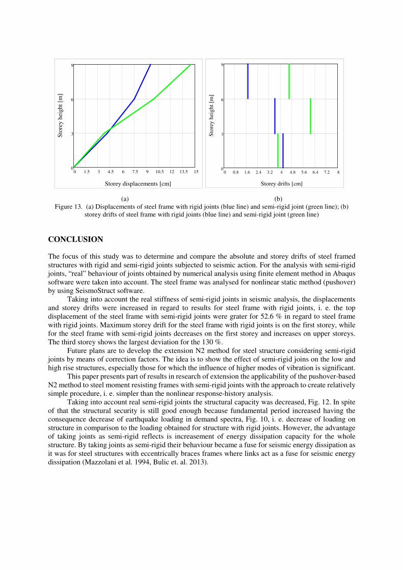
(a) (b)
Figure 13. (a) Displacements of steel frame with rigid joints (blue line) and semi-rigid joint (green line); (b)
storey drifts of steel frame with rigid joints (blue line) and semi-rigid joint (green line)
CONCLUSION
The focus of this study was to determine and compare the absolute and storey drifts of steel framed
structures with rigid and semi-rigid joints subjected to seismic action. For the analysis with semi-rigid
joints, “real” behaviour of joints obtained by numerical analysis using finite element method in Abaqus
software were taken into account. The steel frame was analysed for nonlinear static method (pushover)
by using SeismoStruct software.
Taking into account the real stiffness of semi-rigid joints in seismic analysis, the displacements
and storey drifts were increased in regard to results for steel frame with rigid joints, i. e. the top
displacement of the steel frame with semi-rigid joints were grater for 52.6 % in regard to steel frame
with rigid joints. Maximum storey drift for the steel frame with rigid joints is on the first storey, while
for the steel frame with semi-rigid joints decreases on the first storey and increases on upper storeys.
The third storey shows the largest deviation for the 130 %.
Future plans are to develop the extension N2 method for steel structure considering semi-rigid
joints by means of correction factors. The idea is to show the effect of semi-rigid joins on the low and
high rise structures, especially those for which the influence of higher modes of vibration is significant.
This paper presents part of results in research of extension the applicability of the pushover-based
N2 method to steel moment resisting frames with semi-rigid joints with the approach to create relatively
simple procedure, i. e. simpler than the nonlinear response-history analysis.
Taking into account real semi-rigid joints the structural capacity was decreased, Fig. 12. In spite
of that the structural security is still good enough because fundamental period increased having the
consequence decrease of earthquake loading in demand spectra, Fig. 10, i. e. decrease of loading on
structure in comparison to the loading obtained for structure with rigid joints. However, the advantage
of taking joints as semi-rigid reflects is increasement of energy dissipation capacity for the whole
structure. By taking joints as semi-rigid their behaviour became a fuse for seismic energy dissipation as
it was for steel structures with eccentrically braces frames where links act as a fuse for seismic energy
dissipation (Mazzolani et al. 1994, Bulic et. al. 2013).
0 1.5 3 4.5 6 7.5 9 10.5 12 13.5 150
3
6
9
Storey displacements [cm]
Sto
rey h
eight
[m]
0 0.8 1.6 2.4 3.2 4 4.8 5.6 6.4 7.2 80
3
6
9
Storey drifts [cm]
Sto
rey
hei
gh
t [m
]

ACKNOWLEDGMENT
The research presented in this paper was done within the research project "Development of structures
with increased reliability with regard to earthquakes" supported by the University of Rijeka, Croatia
(grant no. 402-01/14-01/11).
REFERENCES
Bulic M, Causevic M and Androic B (2013) “Reliability of short seismic links in shear”, Bulletin of Earthquake
Engineering, 11:1083-1098
Causevic M and Mitrovic S (2011) “Comparison between non-linear dynamic and static seismic analysis of
structures according to European and US provisions”, Bulletin of Earthquake Engineering, 9(2): 467-489
Chopra A.K. (2012) Dynamics of Structures - Theory and Application to Earthquake Engineering, 4th Ed., Prentice
Hall, New Jersey
Eurocode 3 (2005) “Design of steel structures, Part 1-8: Design of joints”, European Committee for
Standardization, CEN, Brussels
Eurocode 8 (2004) “Design of structures for earthquake resistance – Part 1: General rules, seismic actions and
rules for buildings, European Committee for Standardization, CEN, Brussels
Fajfar P (1999) “Capacity Spectrum Method Based on Inelastic Demand Spectra”, Earthquake Engineering and
Structural Dynamics 28, 979-993
Fajfar P, Marusic D and Perus I (2005) “Torsional effects in the pushover-based seismic analysis of buildings”
Journal of Earthquake Engineering, 9(6): 831-854
Kreslin M and Fajfar P (2012) “The extended N2 method considering higher mode effects in both plan and
elevation”, Bulletin of Earthquake Engineering, 10(2): 695-715
Mazzolani F, M, et. al. (1994) “Remarks on Behaviour of Concentrically and Eccentrically Braced Steel Frames”,
Proceedings of the International Workshop organized by the European Convention for Constructional
Steelwork in Timisoara, Romania, E&FN SPON, An Imprint of Chapman & Hall, London, 310-323
Multi-storey buildings in steel - The Swedish development (1997), European Convention for Constructional
Steelwork Nº74, B-1200 Brussels, Belgium
Skejic D, Dujmovic D and Androic B (2008) “Behavior of beam-to-column joints subjected to the static load”,
Structural engineering and Mechanics 29, 17-35
Wang T, Wang Z, Wang J, Feng J (2013) “A Simplified Calculation Model for Moment-rotation Curve Used in
Semi-rigid End-plate Connection”, Journal of Information & Computational Science 10:11, 3529-3538


